1
Komodo™ CAN Interface GUI
Supported products:
Komodo GUI
User Manual v1.51
February 28, 2014
Summary
The Komodo GUI is a graphical application for use with the Komodo
CAN Interface. The application provides access to CAN Bus
Monitoring as well as an Activity Board Mode, designed for use with
the CAN/I2C Activity Board Pro.
Komodo GUI User Manual
1 Overview
The Komodo CAN Interface is a CAN interface capable of active CAN data transmission
as well as non-intrusive CAN bus monitoring. The Komodo CAN Interface GUI software
interacts directly with the Komodo interface.
The Komodo GUI is built upon the freely available Komodo Software API as detailed in
the Komodo CAN Interface datasheet.
1.1 Komodo CAN Duo Interface
The Komodo CAN Duo Interface has two independent, customizable CAN channels
along with eight configurable GPIOs. The Komodo interface also has two virtual USB
ports (via a single physical USB port).
The two CAN channels make simultaneous communication on and/or monitoring of two
separate CAN buses possible using a single Komodo CAN Duo Interface.
GPIO, General Purpose IO, allows users to synchronize external logic with a CAN
channel, as well as output events to external devices, such as oscilloscopes.
The two virtual USB ports allow users to communicate with a single Komodo interface
simultaneously from two software applications.
1.2 Komodo CAN Solo Interface
The Komodo CAN Solo Interface has one customizable CAN channel along with eight
configurable GPIOs. The Komodo interface also has one virtual USB port.
GPIO, General Purpose IO, allows users to synchronize external logic with a CAN
channel, as well as output events to external devices, such as oscilloscopes.
1.3 Changes in version 1.51
• Improved USB driver support for Linux.
1.4 Changes in version 1.50
CAN
• Added Komodo CAN Solo Interface.
2
Komodo GUI User Manual
1.5 Changes in version 1.40
CAN
• Added batch mode interface.
1.6 Changes in version 1.30
CAN
• Added ability to send messages periodically.
• Improved performance during long captures.
1.7 Changes in version 1.20
CAN
• Added GPIO interface.
1.8 Changes in version 1.11
CAN
• Fixed an issue when exporting in General CAN mode.
1.9 Changes in version 1.10
CAN
• Added ability to send arbitrary CAN packets.
• Added automatic CAN bitrate detection.
• Fixed minor sizing issues.
• Minor bug fixes.
3
Komodo GUI User Manual
2 Getting Started
2.1 Requirements
2.1.1 Overview
The following sections describe the requirements to run the Komodo CAN Interface GUI
software. Be sure the device driver has been installed prior to plugging in the Komodo
interface. Refer to the Komodo datasheet for additional information regarding the driver
and compatibility.
2.1.2 Windows
The Komodo GUI software is compatible with Windows XP, Windows Vista, and
Windows 7. The software will run on 64-bit systems as a 32-bit application.
2.1.3 Linux
The Komodo GUI software has been designed for Red Hat Enterprise Linux 4 and 5 with
integrated USB support. Kernel 2.6 or newer is required. The software will run on 64-bit
systems as a 32-bit application.
2.1.4 Mac OS X
The Komodo GUI software is compatible with Intel versions of Mac OS X 10.5 Leopard,
10.6 Snow Leopard, 10.7 Lion, 10.8 Mountain Lion, and 10.9 Mavericks. Installation of
the latest available update is recommended.
2.2 Installing the Komodo GUI
The Komodo GUI software is a self-contained application. Installing the software is as
easy as unpacking the archive containing the software package. To install the Komodo
GUI:
1. Download the latest version of the software from the Total Phase website.
4
Komodo GUI User Manual
2. Unzip the zip archive to your desired location.
2.3 Launching the Komodo GUI
2.3.1 Windows
1. Go to the folder where the software package was extracted.
2. Click on "Komodo GUI.exe"
2.3.2 Linux
1. Go to the installation directory where the software package was unzipped.
2. Run >./Komodo\ GUI
To communicate on or monitor a CAN bus, the Komodo GUI software must be
connected to a Komodo interface. When a Komodo interface virtual port is connected to
the software, it will be unavailable for use by another process until the port is
disconnected from the process or the application is terminated. Because each Komodo
CAN Duo Interface has two virtual ports, two application instances can be
simultaneously connected to a single Komodo CAN Duo Interface. Only one application
instance can be connected to a single Komodo CAN Solo Interface.
2.3.3 Connect a Komodo Port
5
Komodo GUI User Manual
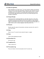
Figure 1 : Komodo Interface Connect Window
The Connect window displays a list of available Komodo
ports and their serial numbers.
The configuration window (Figure 1 ) has a list of available Komodo ports and their
version information.
List of Available Komodo Ports
In the connect window, there is a list of all the available Komodo ports. If no Komodo
ports appear in the list, then there are no available Komodo interface ports connected to
your computer.
Refresh rescans the USB bus and updates the list of Komodo ports
Please note that Komodo ports that are in use by other applications are not available for
use. These ports are shown with a red connection dot to the left of the port number in the
Connect window (see Figure 1 ).
The list of Komodo ports provides the following information:
Port
The port number is a zero based identifier. For more information about Komodo port
assignments please consult the relevant sections of the Komodo CAN Interface
datasheet.
Serial Number
The serial number of the Komodo interface with which the port number is associated.
Selecting the Mode
Ports can be opened in either Activity Board Mode, Batch Mode, or in General CAN
Mode. For more information on GUI modes, refer to Section 3.
Opening a Komodo Port
Click "OK" to connect to the desired Komodo port. You can also double-click on the
selected entry in the list.
The port and serial number of the Komodo interface will appear in the status bar at the
bottom of the window to indicate which Komodo interface is being used in this instance
of the application.
6
Komodo GUI User Manual
2.4 Switching Modes
The current application mode can be changed by clicking on the Mode menu. The
shortcut keys for the two modes are:
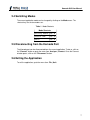
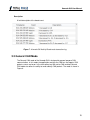
Table 1 : Mode Shortcuts
Mode Shortcuts
Activity Board Ctrl + B
General CAN
Ctrl + G
Batch
Ctrl + A
2.5 Disconnecting from the Komodo Port
The Komodo port can be disconnected from the current application. To do so, click on
the "Connect" button or go to the menu item: Analyzer | Connect. Once the Connect
window opens, click on the "Disconnect" button.
2.6 Exiting the Application
To exit the application, go to the menu item: File | Quit.
7
Komodo GUI User Manual
3 Application
3.1 General
3.1.1 Setting the Bitrate Automatically
The bitrate can be set automatically by pressing the "Auto Bitrate Button". When the
button is pressed, a dialog will appear, displaying the operations progress. The operation
can be canceled at any time by pressing the "Abort" button in the dialog.
The Komodo interface will cycle through the following bitrates and determine if any
match the bitrate used on the connected CAN bus.
• 1000 kHz
• 500 kHz
• 250 kHz
• 125 kHz
• 100 kHz
• 50 kHz
• 25 kHz
• 20 kHz
Once the bitrate detection operation completes, the pass/fail result is displayed in the
progress dialog. Red text indicates a failure to detect bitrate. Green text indicates a
successful bitrate lock.
The progress dialog is automatically dismissed shortly after the bitrate operation result is
displayed. The new bitrate will appear in the Bitrate Field of the toolbar. The Bitrate
Field will pulse red to indicate failure to detect bitrate, or green to indicate successful
bitrate detection.
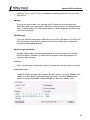
3.1.2 Setting the Bitrate Manually
The bitrate can be manually configured by entering a bitrate value in the Bitrate Field of
the toolbar. Once a bitrate has been entered, click Enter or click on the green check icon
to set the bitrate. Click the red X icon to revert to the previous bitrate.
8
Komodo GUI User Manual
The resulting bitrate may slightly different from the entered value, as only certain discrete
bitrates are permitted. The application will set the bitrate to the value nearest the entered
bitrate.
Figure 2 : Bitrate setting widgets in the toolbar
3.1.3 Toggling the CAN Channel
The Komodo GUI can use either CAN channel (A or B) on the connected Komodo CAN
Duo Interface. The default channel is A. Only channel A is available on the Komodo CAN
Solo Interface, and this button is disabled.
CAN Channel toggles between A and B when the button is pressed
3.1.4 Session Management
The session management controls and indicators in the toolbar are as follows:
Start Capture begins a capture
Stop Capture ends a running capture
Capture Indicator shows that a capture is running by pulsing green
3.1.5 Log Management
Clear Log clears the transaction log ( File | Clear Log or Ctrl + L )
Export Log opens a CSV export dialog ( File | Export Log or Ctrl + E )
Create Batch Script creates the batch script for replaying the log in
the batch mode ( File | Create Batch Script or Ctrl + P )
Scroll Off disables log scrolling
9
Komodo GUI User Manual
Scroll On enables log scrolling, but scrolling will disable on user interaction with the
log
Scroll Locked enables scrolling and locks scrolling against user interaction with
the log
3.2 Activity Board Mode
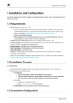
The Activity Board mode of the Komodo GUI is designed specifically for the CAN/I2C
Activity Board Pro. In this mode, the application polls the CAN devices on the CAN/I2C
Activity Board Pro and updates the GUI accordingly. The mode is shown in Figure 3.
10
Komodo GUI User Manual
11
Komodo GUI User Manual
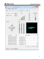
Figure 3 : Activity Board Mode
Activity Board Mode presents the status of the CAN/I2C
Activity Board Pro CAN devices through graphical widgets
and a transaction log.
3.2.1 Inputs
Polling Interval
The rate in milliseconds at which the application will poll the CAN/I2C Activity Board Pro
for sensor updates (light, temperature, etc.). See Figure 4.
Display
The text to display on the CAN/I2C Activity Board Pro LCD. See Figure 4.
LEDs
The LED buttons toggle the on/off value of the CAN/I2C Activity Board Pro userconfigurable LEDs. The LED buttons are arranged, top to bottom, in this order: LED 3,
2, 1. The order of LEDs on the CAN/I2C Activity Board Pro is, left to right, in this order:
LED 3, 2, 1. See Figure 4.
Figure 4 : (a) Polling and Display inputs (b) LED settings
3.2.2 Outputs
Light
The light intensity, as detected by the the CAN/I2C Activity Board Pro light sensor. The
more yellow bars, the higher the light intensity. See Figure 5.
12
Komodo GUI User Manual
Temperature
The ambient temperature, as detected by the CAN/I2C Activity Board Pro temperature
sensor. The more filled the temperature bar, the higher the temperature. See Figure 5.
Joystick
The current position of the CAN/I2C Activity Board Pro 8-way hat switch (joystick). Filled
green arrows show the direction of the joystick. A filled green center indicates that the
joystick is being pressed into the board. See Figure 5.
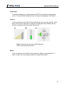
Figure 5 : (a) Light Sensor intensity (b) Temperature
Sensor Value (c) Joystick position
Motion
The 3-axis position of the CAN/I2C Activity Board Pro. Motion is represented via X, Y
and Z axis bars and a visual representation of the board. See Figure 6.
13
Komodo GUI User Manual
Figure 6 : Komodo GUI motion widget for CAN/I2C Activity
Board Pro Motion Sensor
3.2.3 Transaction Log
The transaction log is a scrolling log of the CAN bus events that are related to the CAN/I2
C Activity Board Pro. Log information is arranged into three columns, which are
described below. For information on log scrolling, clearing, and exporting, see Section
3.1.5.
Timestamp
The time at which the event occurred, relative to the start of capture. The time is
displayed in the format (minutes, seconds, milliseconds, microseconds, nanoseconds):
M:ss.mmm.uuu.nnn
Event
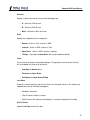
A text description of a CAN/I2C Activity Board Pro event. The following are valid events:
Table 2 : Activity Board Transaction Log Events
Activity Board Transaction Log Events
Display
The LCD text value was changed
Joystick
The board joystick was moved
LEDs
The LED configuration changed
Light
The light intensity changed
Motion
The board position changed
Temperature The ambient temperature changed
14
Komodo GUI User Manual
Description
A brief description of the board event.
Figure 7 : Komodo GUI Activity Board mode transaction log
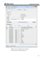
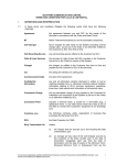
3.3 General CAN Mode
The General CAN mode of the Komodo GUI is designed for general purpose CAN
communication. In this mode, the application monitors the CAN bus and reports CAN
packets, events and errors in the transaction log. With active CAN enabled, General
CAN mode also offers the ability to send arbitrary CAN packets. The mode is shown in
Figure 8.
15
Komodo GUI User Manual
Figure 8 : General CAN Mode reports CAN packets,
events, and errors through a transaction log.
16
Komodo GUI User Manual
3.3.1 Settings
Active CAN Node
The Active CAN Node checkbox enables packet ACKing on the Komodo port. When the
box is checked, the application will acquire the Control feature from the Komodo port.
When the box is unchecked, the port will act as a passive monitor (listen-only) on the
CAN bus. For more information, refer to the Komodo CAN Interface datasheet.
3.3.2 CAN Control
The CAN Control group box offers a way to send customized packets over a CAN bus.
The various fields and options are described below.
CAN ID
The packet destination node ID. For normal packets, the ID is the node to which the data
is delivered. For remote requests, the ID is the node to which the request is delivered.
Note that the Extended ID field dictates the acceptable CAN ID range.
DLC
Data length code field. Specify the number of data bytes you wish to send here. The
application also uses this value for the DLC field of the outgoing CAN packet.
Extended ID
If checked, the CAN packet ID field will be 29 bits, rather than 11 bits.
Remote Request
Check to make the CAN packet a remote request packet, instead of a normal data
packet. No data will be transmitted in this mode.
One-Shot
If checked, the Komodo will only attempt to transmit the CAN packet once. If a delivery
failure occurs, the packet will not be retransmitted. If one-shot is disabled, the default
17
Komodo GUI User Manual
timeout of 10 ms is used. That is, the Komodo will attempt to retransmit for up to 10 ms
upon failure.
Message
Enter up to 8 bytes of data in the message field. The data will be transmitted to the
destination node, unless the packet is marked as a remote request. The highlighted data
bytes, as determined by DLC and Remote Request, indicate the portion of the message
that will be transmitted.
Send Message
Press the Send Message Button or Ctrl + S to transmit the CAN packet. If the CAN ID or
DLC field entries are not valid, the packet will not be transmitted, and a red pulse will
indicate the field needing attention.
Send message periodically
Periodic sending options offer a way to periodically send a message on the CAN bus.
While this option is enabled, it is not possible to change the message parameters or
send messages manually.
Period(ms)
Enter a time period in milliseconds to specify how often the message will be transmitted.
Enable/Disable button
Toggle this button to enable and disable the periodic sending. If you click "Enable" while
capture is running, periodic sending will begin right away. If you click "Enable" while
capture is not running, periodic sending will begin as soon as the capture starts.
18
Komodo GUI User Manual
Figure 9 : Komodo GUI General CAN mode CAN Control
box
3.3.3 GPIO Settings
Figure 10 : The GPIO Settings dialog offers a way to
configure, get current values and set new values of GPIO
pins
The GPIO Settings dialog offers a way to configure, get current values of and set new
values of general purpose input and output (GPIO) pins. While the dialog is open, all
options in the main window are also accessible.
Changing the pin configuration is allowed only when the application is connected to the
Komodo interface and the Komodo interface is not in the running state. Changing the pin
values and querying for the current state of the pins is only allowed when the Komodo
interface is in the running state.
Each of the pins labeled with IN 1, IN 2, IN 3, IN 4 can be configured as an input by
dragging one of the inputs from Configure Input section and dropping it on one of these
pins. Each of the pins labeled with OUT 1, OUT 2, OUT 3, OUT 4 can be configured as
19
Komodo GUI User Manual
an output by dragging one of the outputs from Configure Output section and dropping it
on one of these pins. The various options for each pin type are described below.
Configure Input
Digital inputs allow users to synchronize external logic with a CAN channel. Whenever
the state of an enabled digital input changes, an event will be sent to the analysis PC
and displayed in the transaction log.
• Rising Edge – Report change on rising edge.
• Falling Edge – Report change on falling edge.
• Both Edges – Report change on both edges.
The digital input options are as follows:
Bias
Specify a voltage bias for an input pin.
• Pull-Down – Pulls down input voltage using high impedance resistor to GND.
• Pull-Up – Pulls up input voltage using high impedance resistor to 3.3 V.
• Hi-Z – No modification to input voltage.
Configure Output
Digital outputs allow users to output events to external devices. A common use for this
feature is to trigger an oscilloscope or logic analyzer to capture data. The output pins can
be activated on the various conditions below. Refer to the Komodo datasheet for details
on the output signal characteristics and refer to the CAN specification for details on the
different error types.
• Any Error – Output pulse on any error.
• Bit Error – Output pulse on bit error.
• Form Error – Output pulse on form error.
• Stuff Error – Output pulse on stuff error.
• Other Error – Output pulse on other error.
• Software – Control the output levels via software.
The digital output options are as follows:
20
Komodo GUI User Manual
Channel
Specify a source channel for an error activated output pin.
• A – Active on CAN A error.
• B – Active on CAN B error.
• Both – Active on CAN A or B error.
Drive
Specify the voltage drive for an output pin.
• Normal – Active is 3.3V; Inactive is GND.
• Inverted – Active is GND; Inactive is 3.3V.
• Open Drain – Active is GND; Inactive is floating.
• +Pullup – Equivalent to Open Drain with a high impedance pullup.
Value
Set a value for a software controlled output pin. Changing the value for one of the pins
will also update last state for all of the pins.
• Low/High for Normal drive.
• Float/Low for Open Drain.
• Pullup/Low for Open Drain+Pullup.
Last State
Shows the state of each pin from the last time it was checked. Values in this column get
updated when one of the following happens:
• Komodo is activated.
• "Get All Values" button is clicked.
• State of one of the software activated pins is manually changed in this dialog.
Get All Values
Update Last State for all of the pins.
21
Komodo GUI User Manual
Defaults
Set the default configuration for all of the pins. This will configure IN pins as inputs with
pull-downs that report changes on both edges and OUT pins as software controlled
outputs.
3.3.4 Transaction Log
The transaction log is a scrolling log of CAN bus events, including CAN packets, errors,
capture start, and capture stop. Log information is arranged into five columns, which are
described below. For information on log scrolling, clearing, and exporting, see Section
3.1.5.
Timestamp
The Timestamp field is identical to the Timestamp field in Activity Board Mode. See
Section 3.2.3.1.
ID
The ID of the source CAN node of the CAN packet. When a packet is marked as RTR,
the ID, instead, corresponds to the destination CAN node (the requestee).
RTR
RTR (Remote Transmission Request) is either 0 (not RTR) or 1 (RTR), and indicates
whether or not the CAN packet is marked as a Remote Transmission Request.
DLC
DLC (Data Length Code) is the specified number of bytes transmitted in a single CAN
packet.
Data
The Data field contains the data payload for CAN packets, and a textual description for
CAN events, errors, and capture events.
22
Komodo GUI User Manual
Figure 11 : Komodo GUI General CAN mode transaction
log
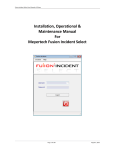
3.4 Batch Mode
The Batch mode of the Komodo GUI is designed for creating and executing batch scripts
for sending arbitrary CAN packets. In this mode, the application also monitors the CAN
bus and reports CAN packets, events and errors in the transaction log. The mode is
shown in Figure 12. Batch script can be automatically created from the existing capture
in the General CAN Transaction Log by clicking the "Create Batch Script" button. One
send command will be generated for each CAN data or remote packet in the log.
23
Komodo GUI User Manual
Figure 12 : Batch Mode allows creating and executing
batch scripts for sending arbitrary CAN packets.
24
Komodo GUI User Manual
3.4.1 Batch Script Editor
Batch Script Editor uses Python syntax. This means that local variables can be defined,
control structures can be used, and comments starting with a hash character (#) can be
inserted as well. For more information on Python syntax and data structures, see http://
www.python.org. For the specifics of the Komodo CAN Interface commands, please
refer to the Batch Mode documentation accessible from the Batch Mode panel of the
Komodo GUI application.
3.4.2 Output Window
The output window is located right below the script editor and contains all the output
generated from the script including print statements and exceptions thrown during the
execution or compilation of the script. At the start of the program, the output window is
hidden, and it will become visible as soon as some output is generated. Script editor and
output window can be re-sized by dragging the boundary between them.
3.4.3 Execute
Start the script. The capture will automatically start before execution of the script if it is
not running already.
3.4.4 Stop
Abort the script. The script will also be aborted if capture is stopped.
3.4.5 Help
Open the Batch Mode documentation.
3.4.6 Save Batch File
Save current script.
3.4.7 Load Batch File
Load a script from file.
3.4.8 Transaction Log
Please see Section 3.3.4 for the description of the Transaction Log.
25
Komodo GUI User Manual
4 Notes
4.1 Multiple Application Instances
It is possible to access a single Komodo CAN Duo Interface from two separate
applications, simultaneously. To do so from the Komodo GUI, simply launch a second
instance of the application and connect to the second Komodo port. It is not possible to
do this with Komodo CAN Solo Interface.
4.2 Technical Specifications
Detailed Technical Specifications for the Komodo CAN Interface and the CAN/I2C
Activity Board Pro are available on the Total Phase website: http://www.totalphase.com/
26
Komodo GUI User Manual
5 Legal / Contact
5.1 Disclaimer
All of the software and documentation provided in this datasheet, is copyright Total
Phase, Inc. ("Total Phase"). License is granted to the user to freely use and distribute
the software and documentation in complete and unaltered form, provided that the
purpose is to use or evaluate Total Phase products. Distribution rights do not include
public posting or mirroring on Internet websites. Only a link to the Total Phase download
area can be provided on such public websites.
Total Phase shall in no event be liable to any party for direct, indirect, special, general,
incidental, or consequential damages arising from the use of its site, the software or
documentation downloaded from its site, or any derivative works thereof, even if Total
Phase or distributors have been advised of the possibility of such damage. The software,
its documentation, and any derivative works is provided on an "as-is" basis, and thus
comes with absolutely no warranty, either express or implied. This disclaimer includes,
but is not limited to, implied warranties of merchantability, fitness for any particular
purpose, and non-infringement. Total Phase and distributors have no obligation to
provide maintenance, support, or updates.
Information in this document is subject to change without notice and should not be
construed as a commitment by Total Phase. While the information contained herein is
believed to be accurate, Total Phase assumes no responsibility for any errors and/or
omissions that may appear in this document.
5.2 Life Support Equipment Policy
Total Phase products are not authorized for use in life support devices or systems. Life
support devices or systems include, but are not limited to, surgical implants, medical
systems, and other safety-critical systems in which failure of a Total Phase product could
cause personal injury or loss of life. Should a Total Phase product be used in such an
unauthorized manner, Buyer agrees to indemnify and hold harmless Total Phase, its
officers, employees, affiliates, and distributors from any and all claims arising from such
use, even if such claim alleges that Total Phase was negligent in the design or
manufacture of its product.
5.3 Contact Information
Total Phase can be found on the Internet at http://www.totalphase.com/. If you have
support-related questions, please go to the Total Phase website. For sales inquiries,
please contact [email protected].
27
Komodo GUI User Manual
©2011-2014 Total Phase, Inc.
All rights reserved.
28