1
Komodo™ Interfaces
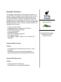
The Komodo™ CAN (Controller Area Network) Interfaces are
powerful ISB-to-CAN adapters. The Komodo interfaces are all-inone tools capable of active CAN data transmission as well as
non-intrusive CAN bus monitoring. The portable and durable
Komodo interfaces easily integrate into end-user systems. They
provide flexible and scalable solutions for a variety of applications
including automotive, military, industrial, medical, and more. All
Komodo interfaces feature:
•
•
•
•
•
•
•
•
Transfer rate up to 1 Mbps
Independent galvanic isolation per CAN channel
Error detection and time-stamping
Precise timing resolution
8 configurable GPIOs
USB 2.0 Full-Speed; bus-powered
Free software and API
Cross-platform support: Windows, Linux, and Mac OS X
compatible
Komodo CAN Duo Interface
Features
• Two independent customizable CAN channels in single
enclosure
• Controllable from two separate desktop applications
• Optimized for applications requiring dual CAN channels
Komodo CAN Solo Interface
Features
• Single customizable CAN channel
• Controllable from a single desktop application
Supported products:
Komodo CAN Interfaces
User Manual v1.22
February 28, 2014
Komodo CAN Interface User Manual
1 General Overview
1.1 CAN Background
1.1.1 CAN History
CAN (Controller Area Network) is a serial bus protocol created in the mid-1980s by the
German company Bosch. It is optimized for sending small amounts of data between
multiple nodes. CAN is not a fast bus by today's standards, with a maximum data rate of
only 1 Megabit per second. However, operating at low data rates makes CAN quite
robust to noise and allows buses to span long distances.
CAN was originally designed for use in automobiles, but has also become popular in
low-bandwidth industrial applications such as controlling assembly line machines.
Although Boschs CAN specification does not define standard CAN voltages or connector
interfaces, standards organizations have defined multiple physical standards. The most
common CAN physical layer standard is ISO 11898-1, but others are also used.
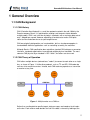
1.1.2 CAN Theory of Operation
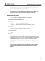
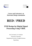
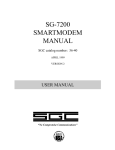
CAN allows multiple devices (referred to as "nodes") to connect to each other on a single
bus, as shown in Figure 1. Unlike other protocols, such as I2C and SPI, CAN nodes do
not have strict master/slave roles. Instead, each CAN node may operate as a transmitter
or receiver at any time.
Figure 1 : Multiple nodes on a CAN bus.
Rather than sending data to specific targets, data messages are broadcast to all nodes
on the bus. Each receiver node decides for itself if the data is relevant by looking at the
2
Komodo CAN Interface User Manual
message frame's "identifier," which describes the content of the message. A message's
identifier also represents the priority and allows for automatic arbitration when multiple
nodes try to transmit at the same time.
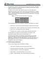
A CAN bus can have two bit states: dominant or recessive. If one node sends a
dominant bit and another sends a recessive bit, the result will be dominant (as shown in
Table 1). Automatic arbitration is built in to the CAN protocol as all nodes must monitor
the bus state during transmission and cease transmission if a dominant bit is seen when
sending a recessive bit.
Table 1 : CAN Bus state when two nodes are transmitting
Dominant Recessive
Dominant
Dominant
Recessive Dominant
Dominant
Recessive
The CAN protocol specifies four fundamental frame types which nodes use to interact:
1. Data Frame – carries 0-8 bytes of data, along with an identifier and CRC check
2. Remote Frame – requests a data frame transmission with a certain identifier node
3. Error Frame – transmitted when an error is detected
4. Overload Frame – provides extra delay between data and remote frames
For more details on message frame formatting, please consult Boschs CAN
specification 2.0 and the other resources listed in Section 1.1.5.
Further physical layer details are undefined by CAN specification "so as to allow
transmission medium and signal level implementations to be optimized for their
application." Common physical layer implementations, such as the ISO 11898, use a
balanced differential CAN bus. For more information about the Komodo interfaces
compatibilities, please refer to Section 2.
1.1.3 CAN Features and Benefits
CAN has many important features and benefits, including:
1. Multi-master – All nodes can transmit and receive messages.
2. Automatic prioritization of messages – Based on message identifier.
3. Automatic arbitration – Based on message identifier.
4. High reliability – Achieved through built-in error checking.
5. Robust – High performance, even in difficult electrical environments.
3
Komodo CAN Interface User Manual
6. Configuration flexibility – Nodes can be added to and removed from the bus
without modifying other nodes.
7. Many nodes can be connected on the same bus – CAN 2.0B defines identifiers as
29 bits, providing over 500,000 unique codes.
8. Buses can be very long – On the order of miles and kilometers.
9. Low cost
1.1.4 CAN Drawbacks
Here are a few drawbacks when using CAN:
1. Low-bandwidth – CAN supports a maximum data rate of 1 Mbps. This is not good
for high-bandwidth applications.
2. Small data transfers – data frames can only carry 8 bytes, so CAN is not good for
large data transfers.
3. Protocol overhead – The CAN protocol has a moderate amount of overhead (strict
message formatting, CRC checking, bit-stuffing, etc.) and is more complicated
than other protocols such as I2C and SPI.
CAN is well-suited for connecting many devices that have small amounts of data to
share with each other at low data rates. Applications other than this, such as reading
from a large memory device, would not use CAN.
1.1.5 CAN References
• CAN Specification 2.0 – osch
• Controller Area Network Wikipedia article – Wikipedia
• Good introduction to CAN – Staffan Nilsson
4
Komodo CAN Interface User Manual
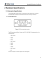
2 Hardware Specifications
2.1 Connector Specification
The Komodo CAN Interfaces feature a connector for each CAN channel: a common
DB-9 connector and a block screw terminal which wires can easily connect to.
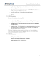
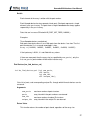
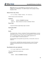
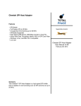
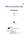
2.1.1 D-Sub Connector
Figure 2 : DB-9 connector pin numbers
The DB-9 connector of Figure 2 follows the SAE J1939 CAN-CIA standard and has the
following pinout:
1. No Connect
2. CAN3. GND
4. No Connect
5. SHLD
6. GND
7. CAN+
8. No Connect
9. V+
Please see Section 2.3 for descriptions of the CAN signals.
5
Komodo CAN Interface User Manual
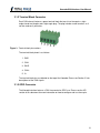
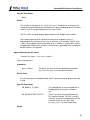
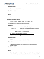
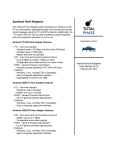
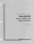
2.1.2 Terminal Block Connector
Each CAN channel features a green terminal block that consists of two parts: a rightangle closed-end header and a right-angle plug. The plug includes screw terminals so it
can be used easily with wires.
Figure 3 : Terminal block pin numbers
The terminal block pinout is as follows:
1. GND
2. CAN3. SHLD
4. CAN+
5. V+
The terminal block pins are labeled on the top of the Komodo. Please see Section 2.3 for
descriptions of the CAN signals.
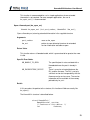
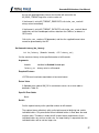
2.1.3 GPIO Connector
The Komodo interface features a DIN-9 connector for GPIO use. Please see the API
section of this document for more information on how to configure and use these pins.
6
Komodo CAN Interface User Manual
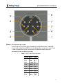
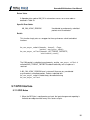
Figure 4 : DIN-9 connector pin numbers
Even though the GPIO DIN-9 cable included with the Komodo interface is labled with
4 inputs and 4 outputs, each GPIO pin can be configured as an input or an ouput. Table
2 shows the pinout for the DIN-9 connector on the Komodo interface along with
corresponding color and label on the cable.
Table 2 : GPIO Cable Pin Assignments
Number Color
Label
Pin 1
Brown
IN 1
Pin 2
Red
IN 2
Pin 3
Orange IN 3
Pin 4
Yellow
IN 4
Pin 5
Green
OUT 1
Pin 6
Blue
OUT 2
Pin 7
Purple
OUT 3
Pin 8
Grey
OUT 4
Pin 9
Black
GND
7
Komodo CAN Interface User Manual
2.1.4 USB Connector
One side of the Komodo CAN Interfaces features a single USB-B receptacle. This port
connects to the analysis computer that runs the software or a custom application. This
port must be plugged in to provide power to the Komodo CAN Interface and to power the
CAN bus over V+ (if enabled).
2.2 GPIO
Digital inputs allow users to synchronize external logic with a CAN channel. Whenever
the state of an enabled digital input changes, an event will be sent to the analysis PC.
Digital outputs allow users to output events to external devices. These pins can be set to
activate on various conditions that are described more thoroughly in Section 5. A
common use for this feature is to trigger an oscilloscope or logic analyzer to capture
data.
Note that the GPIO's ground is the same as the USB's ground, and is isolated from each
of the CAN grounds.
2.2.1 GPIO Configuration
GPIO pins can be individually configured as either inputs or outputs. Input pins can be
configured to have a pull-up, pull-down, or no resistor enabled. The internal pull-up
resistors have a nominal value of 1.5 k.
Output pins may be configured as active high, active low, open-drain, or open-drain with
internal pull-up.
Please see Section 5 for more information on the API.
2.2.2 GPIO Signaling
The GPIO pins have a logical high output of 3.3 V. When configured as inputs, the
GPIOs can withstand a maximum input of 5.5 V. Exceeding this will damage the device.
Additional GPIO pin specifications are listed in Table 3.
Table 3 : GPIO Pin Voltages
8
Komodo CAN Interface User Manual
Input Output
V_L_MAX 1.0 V
0.4 V
V_H_MIN
2.9 V
2.3 V
2.3 CAN Signal Descriptions
This section describes the function of the Komodo interface's signals. For connector
pinout information, please see Section 2.1.1.
2.3.1 GND
Ground – The ground of the CAN channels are galvanically isolated from each other and
the Komodo interface's circuitry. Each channel's CAN- and CAN+ signals are referenced
to their respective ground pin. If a channel's ground is not connected, the signaling is
entirely unpredictable and communication will likely be corrupted. Two pins on the DB-9
are connected to ground to provide a solid ground path, though it is only necessary to
connect to one of these.
2.3.2 CANDominant Low – When a dominant bit is transmitted, the voltage of this pin is lower than
CAN+. When configured as an input, voltage may range from -12 V to 12 V. See
Section 2.5.1 for more details.
2.3.3 CAN+
Dominant High – When a dominant bit is transmitted, the voltage of this pin is higher
than CAN-. When configured as an input, Voltage may range from -12 V to 12 V. See
Section 2.5.1 for more details.
2.3.4 V+
Power – The Komodo interfaces can optionally source power to the CAN bus. If enabled,
the Komodo CAN Interfaces will provide approximately 4.8 V out on this pin and can
source up to 73mA (per CAN channel). The Komodo will illuminate the CAN power LED
if power is detected on this pin.
The input voltage on V+ should not exceed 30 V.
2.3.5 SHLD
CAN Shield – This pin may optionally be connected to the CAN bus shield.
9
Komodo CAN Interface User Manual
2.3.6 No Connect
No Connect – Reserved for future use. Internally, these pins are floating.
2.3.7 Powering Downstream Devices
It is possible to power one or more downstream CAN nodes using the V+ pin. The
Komodo CAN Interfaces can source a maximum of 73 mA per CAN channel with V+.
This current comes from the analysis PC's {{vbus}. See Section 2.7 for more details.
2.4 LED Indicators
The Komodo CAN Duo Interface has five LEDs in total and the Komodo CAN Solo
Interface has three. The green LED labeled "USB" serves as a global power indicator. It
illuminates when the Komodo interface is correctly connected to an analysis computer
and is receiving power over USB.
Each CAN interface features two LEDs: an activity LED and a bi-color power LED. The
bi-color power LEDs illuminate white when the Komodo interface is sourcing V+ to the
CAN bus, and illuminate blue when the CAN bus is powered externally. The power LEDs
will be off if power is neither observed nor sourced.
The CAN activity LEDs are orange, and their blink rate is proportional to the amount of
CAN data transmitted on the bus. If no data is being sent on an active CAN channel, the
activity LED will simply remain on without blinking.
2.5 Signal Levels/Voltage Ratings
2.5.1 Logic Levels
The Komodo interface signal specifications for transmitted dominant and recessive
states are listed in Tables 4 and 5, respectively.
Monitored CAN signals may range from -12V to 12V.
These signal levels apply to both transmitter and monitor modes.
Table 4 : Dominant State Output Voltage Levels
Signal
Minimum V Nominal V Maximum V
CAN+
2.9
3.5
4.5
CAN-
0.8
1.2
1.5
Differential
1.4
3.0
Table 5 : Recessive State Output Voltage Levels
10
Komodo CAN Interface User Manual
Signal
Both CAN lines
Differential
Minimum V Nominal V Maximum V
2
2.3
-0.5
3.0
0.05
2.5.2 ESD protection
The Komodo interface has built-in electrostatic discharge protection to prevent damage
to the unit from high voltage static electricity.
2.5.3 Input Current
The Komodo interface may draw up to 4 mA on the CAN+ and CAN- lines when
operating as a receiver.
2.5.4 Drive Current
The Komodo interface can drive all output signals with a maximum of 73 mA current
source or sink. Drawing more than this may damage the hardware.
2.5.5 Capacitance
The Komodo interface may add up to 23 pF capacitance on the CAN+ and CAN- lines.
2.6 CAN Signaling Characteristics
2.6.1 Speed
The Komodo interface may operate at a maximum bitrate of 1 Mbps. Not all bitrates are
supported. When an attempt is made to set the bitrate, the Komodo interface will be set
to the closest supported value less than or equal to the requested value.
2.7 Komodo Device Power Consumption
The Komodo interface consumes less than 150 mA from the host PC and reports itself
as a high-powered device. The Komodo interface should be plugged directly into the
host PC's USB host port or a self-powered hub. The Komodo interface should not be
connected to a bus-powered hub because these are only specified to supply 100 mA per
port.
Using the Komodo interface to supply power to CAN nodes will draw extra current from
VBUS.
11
Komodo CAN Interface User Manual
2.8 USB 2.0
The Komodo interface is a full-speed USB 2.0 device.
2.9 Temperature Specifications
The Komodo CAN Interfaces are industrial grade products, rated for operating
temperatures from -40 to 85°C. Any use of the Komodo interfaces outside the industrial
grade temperature specification will void the hardware warranty.
12
Komodo CAN Interface User Manual
3 Software
3.1 Compatibility
3.1.1 Overview
The Komodo software is offered as a 32-bit or 64-bit Dynamic Linked Library (or shared
object). The specific compatibility for each operating system is discussed below. Be sure
the device driver has been installed before plugging in the Komodo interface.
3.1.2 Windows Compatibility
The Komodo software is compatible with Windows XP (SP2 or later, 32-bit and 64-bit),
Windows Vista (32-bit and 64-bit), and Windows 7 (32-bit and 64-bit). Windows 2000
and legacy 16-bit Windows 95/98/ME operating systems are not supported.
3.1.3 Linux Compatibility
The Komodo software is compatible with all standard 32-bit and 64-bit distributions of
Linux with kernel 2.6 and integrated USB support. When using the 32-bit library on a 64bit distribution, the appropriate 32-bit system libraries are also required.
3.1.4 Mac OS X Compatibility
The Komodo software is compatible with Intel versions of Mac OS X 10.5 Leopard,
10.6 Snow Leopard, 10.7 Lion, 10.8 Mountain Lion, and 10.9 Mavericks. Installation of
the latest available update is recommended.
3.2 Windows USB Driver
3.2.1 Driver Installation
To install the appropriate USB communication driver under Windows, use the Total
Phase USB Driver Installer before plugging in any device. The driver installer can be
found either on the CD-ROM (use the HTML based guide that is opened when the CD is
first loaded to locate the Windows installer), or in the Downloads section of the Komodo
interface product page on the Total Phase website.
After the driver has been installed, plugging in a Komodo interface for the first time will
cause the interface to be installed and associated with the correct driver. The following
13
Komodo CAN Interface User Manual
steps describe the feedback the user should receive from Windows after a Komodo
interface is plugged into a system for the first time:
Windows XP:
1. The Found New Hardware notification bubble will pop up from the system tray
and state that the "Total Phase Komodo CAN Duo Interface" or "Total Phase
Komodo CAN Solo Interface" has been detected.
2. When the installation is complete, the Found New Hardware notification bubble
will again pop up and state that "your new hardware is installed and ready to use."
To confirm that the device was correctly installed, check that the device appears in the
"Device Manager". To navigate to the "Device Manager" in Windows XP, select "Control
Panel | System Properties | Hardware | Device Manager". The Komodo interface should
appear under the "Universal Serial Bus Controllers" section.
Windows Vista/7:
1. A notification bubble will pop up from the system tray and state that Windows is
"installing device driver software."
2. When the installation is complete, the notification bubble will again pop up and
state that the "device driver software installed successfully."
To confirm that the device was correctly installed, check that the device appears in the
"Device Manager." To navigate to the "Device Manager" screen in Windows Vista/7,
select "Control Panel | Hardware and Sound | Device Manager". The Komodo interface
should appear under the "Universal Serial Bus Controllers" section.
3.2.2 Driver Removal
The USB communication driver can be removed from the operating system by using the
Windows program removal utility. Instructions for using this utility can be found below.
Alternatively, the Uninstall option found in the driver installer can also be used to remove
the driver from the system. It is critical that all Total Phase devices have been
disconnected from your system before removing the USB drivers.
Windows XP:
1. Select "Control Panel | Add or Remove Programs"
2. Select "Total Phase USB Driver" and select "Change/Remove"
14
Komodo CAN Interface User Manual
3. Follow the instructions in the uninstaller
Windows Vista/7:
1. Select "Control Panel | Uninstall a program"
2. Right-click on "Total Phase USB Driver" and select "Uninstall/Change"
3. Follow the instructions in the uninstaller
3.3 Linux USB Driver
As of version 1.22, the Komodo communications layer under Linux no longer requires a
specific kernel mode or user mode driver to operate. This differs from previous versions
that required the user to ensure independently that the libusb library was installed on the
system. See the README.txt in the API package for more details.
Most modern Linux distributions use the udev subsystem to help manipulate the
permissions of various system devices. This is the preferred way to support access to
the Komodo interface such that the device is accessible by all of the users on the system
upon device plug-in.
For legacy systems, there are two different ways to access the Komodo interface:
through USB hotplug or by mounting the entire USB filesystem as world writable. Both
require that /proc/bus/usb is mounted on the system, which is the case on most
standard distributions.
3.3.1 UDEV
Support for udev requires a single configuration file that is available on the software CD,
and also listed on the Total Phase website for download. This file is 99totalphase.rules. Please follow the following steps to enable the appropriate
permissions for the Komodo interface.
1. As superuser, unpack 99-totalphase.rules to /etc/udev/rules.d
2. chmod 644 /etc/udev/rules.d/99-totalphase.rules
15
Komodo CAN Interface User Manual
3. Unplug and replug your Komodo interface(s)
3.3.2 USB Hotplug
USB hotplug requires two configuration files which are available on the software CD, and
also listed on the Total Phase website for download. These files are: komodo and
komodo.usermap. Please follow the following steps to enable hotplugging.
1. As superuser, unpack komodo and komodo.usermap to /etc/hotplug/usb
2. chmod 755 /etc/hotplug/usb/komodo
3. chmod 644 /etc/hotplug/usb/komodo.usermap
4. Unplug and replug your Komodo interface(s)
5. Set the environment variable USB_DEVFS_PATH to /proc/bus/usb
3.3.3 World-Writable USB Filesystem
Finally, here is a last-ditch method for configuring your Linux system in the event that
your distribution does not have udev or hotplug capabilities. The following procedure is
not necessary if you were able to exercise the steps in the previous subsections.
Often, the /proc/bus/usb directory is mounted with read-write permissions for root
and read-only permissions for all other users. If an non-privileged user wishes to use the
Komodo interface and software, one must ensure that /proc/bus/usb is mounted with
read-write permissions for all users. The following steps can help setup the correct
permissions. Please note that these steps will make the entire USB filesystem world
writable.
1. Check the current permissions by executing the following command:
ls -al /proc/bus/usb/001
2. If the contents of that directory are only writable by root, proceed with the
remaining steps outlined below.
3. Add the following line to the /etc/fstab file:
none /proc/bus/usb usbfs defaults,devmode=0666 0 0
4. Unmount the /proc/bus/usb directory using "umount"
5. Remount the /proc/bus/usb directory using "mount"
6. Repeat step 1. Now the contents of that directory should be writable by all users.
16
Komodo CAN Interface User Manual
7. Set the environment variable USB_DEVFS_PATH to /proc/bus/usb
3.4 Mac OS X USB Driver
The Komodo communications layer under Mac OS X does not require a specific kernel
driver to operate. Both Mac OS X 10.5 Leopard and 10.6 Snow Leopard are supported.
It is typically necessary to ensure that the user running the software is currently logged
into the desktop. No further user configuration should be necessary.
3.5 USB Port Assignment
The Komodo CAN Duo Interface consists of two independent CAN channels and
presents two ports to the computer when connected. The Komodo CAN Solo Interface
consists of one CAN channel and presents one port to the computer when connected.
For example, one connected Komodo CAN Duo Interface would be assigned ports 0 and
1, and a second Komodo CAN Solo Interface would be assigned port 2.
Note that with the Windows operating system, each Komodo interface will appear as two
USB devices in the device manager.
If a Komodo interface is subsequently removed from the system, the remaining
interfaces shift their port numbers accordingly. With n Komodo interfaces attached, the
allocated ports will be numbered from 0 to 2n-1.
3.5.1 Detecting Ports
To determine the ports to which the Komodo interfaces have been assigned, use the
km_find_devices function as described in the API documentation.
3.6 Komodo Dynamically Linked Library
3.6.1 DLL Philosophy
The Komodo DLL provides a robust approach to allow present-day Komodo-enabled
applications to interoperate with future versions of the device interface software without
recompilation. For example, take the case of a graphical application that is written to
communicate CAN through a Komodo interface. At the time the program is built, the
Komodo software is released as version 1.2. The Komodo interface software may be
improved many months later resulting in increased performance and/or reliability; it is
now released as version 1.3. The original application need not be altered or recompiled.
The user can simply replace the old Komodo DLL with the newer one. How does this
work? The application contains only a stub which in turn dynamically loads the DLL on
the first invocation of any Komodo API function. If the DLL is replaced, the application
simply loads the new one, thereby utilizing all of the improvements present in the
replaced DLL.
17
Komodo CAN Interface User Manual
On Linux and Mac OS X, the DLL is technically known as a shared object (SO).
3.6.2 DLL Location
Total Phase provides language bindings that can be integrated into any custom
application. The default behavior of locating the Komodo DLL is dependent on the
operating system platform and specific programming language environment. For
example, for a C or C++ application, the following rules apply:
On a Windows system:
1. The directory from which the application binary was loaded.
2. The application's current directory.
3. 32-bit system directory (for a 32-bit application). Examples:
◦ C:\Windows\System32 [Windows XP/Vista/7 32-bit]
◦ C:\Windows\System64 [Windows XP 64-bit]
◦ C:\Windows\SysWow64 [Windows Vista/7 64-bit]
4. 64-bit system directory (for a 64-bit application). Examples:
◦ C:\Windows\System32 [Windows XP/Vista/7 64-bit]
5. The Windows directory. (Ex: C:\Windows )
6. The directories listed in the PATH environment variable.
On a Linux system this is as follows:
1. First, search for the shared object in the application binary path. If the /proc
filesystem is not present, this step is skipped.
2. Next, search in the applications current working directory.
3. Search the paths explicitly specified in LD_LIBRARY_PATH.
4. Finally, check any system library paths as specified in /etc/ld.so.conf and
cached in /etc/ld.so.cache.
On a Mac OS X system this is as follows:
1. First, search for the shared object in the application binary path.
2. Next, search in the applications current working directory.
18
Komodo CAN Interface User Manual
3. Search the paths explicitly specified in DYLD_LIBRARY_PATH.
4. Finally, check the /usr/lib and /usr/local/lib system library paths.
If the DLL is still not found, an error will be returned by the binding function. The error
code is KM_UNABLE_TO_LOAD_LIBRARY.
3.6.3 DLL Versioning
The Komodo DLL checks to ensure that the firmware of a given Komodo device is
compatible. Each DLL revision is tagged as being compatible with firmware revisions
greater than or equal to a certain version number. Likewise, each firmware version is
tagged as being compatible with DLL revisions greater than or equal to a specific version
number.
Here is an example:
DLL v1.20: compatible with Firmware >= v1.15
Firmware v1.30: compatible with DLL >= v1.20
Hence, the DLL is not compatible with any firmware less than version 1.15 and the
firmware is not compatible with any DLL less than version 1.20. In this example, the
version number constraints are satisfied and the DLL can safely connect to the target
firmware without error. If there is a version mismatch, the API calls to open the device
will fail. See the API documentation for further details.
3.7 Rosetta Language Bindings: API Integration into
Custom Applications
3.7.1 Overview
The Komodo Rosetta language bindings make integration of the Komodo API into
custom applications simple. Accessing Komodo functionality simply requires function
calls to the Komodo API. This API is easy to understand, much like the ANSI C library
functions, (e.g. there is no unnecessary entanglement with the Windows messaging
subsystem like development kits for some other embedded tools).
First, choose the Rosetta bindings appropriate for the programming language. Different
Rosetta bindings are included with the software distribution on the distribution CD. They
can also be found in the software download package available on the Total Phase
website. Currently the following languages are supported: C/C++, Python, Visual
Basic 6, Visual Basic .NET, and C#. Next, follow the instructions for each language
binding on how to integrate the bindings with your application build setup. As an
example, the integration for the C language bindings is described below. For more
information on how to integrate the bindings for other languages, please see the
19
Komodo CAN Interface User Manual
example code included on the distribution CD and also available for download on the
Total Phase website.
1. Include the komodo.h file included with the API software package in any C or C+
+ source module. The module may now use any Komodo API call listed in
komodo.h.
2. Compile and link komodo.c with your application. Ensure that the include path for
compilation also lists the directory in which komodo.h is located if the two files
are not placed in the same directory.
3. Place the Komodo DLL, included with the API software package, in the same
directory as the application executable or in another directory such that it will be
found by the previously described search rules.
3.7.2 Versioning
Since a new Komodo DLL can be made available to an already compiled application, it is
essential to ensure the compatibility of the Rosetta binding used by the application (e.g.
komodo.c ) against the DLL loaded by the system. A system similar to the one
employed for the DLL-Firmware cross-validation is used for the binding and DLL
compatibility check. Here is an example:
DLL v1.20: compatible with Binding >= v1.10
Binding v1.15: compatible with DLL >= v1.15
The above situation will pass the appropriate version checks. The compatibility check is
performed within the binding. If there is a version mismatch, the API function will return
an error code, KM_INCOMPATIBLE_LIBRARY.
3.7.3 Customizations
While the provided language bindings stubs are fully functional, it is possible to modify
the code found within this file according to specific requirements imposed by the
application designer.
For example, in the C bindings one can modify the DLL search and loading behavior to
conform to a specific paradigm. See the comments in komodo.c for more details.
3.8 Application Notes
3.8.1 Asynchronous Messages
There is buffering within the Komodo DLL, on a per-device basis, to help capture
asynchronous messages. Take the case of the Komodo interface receiving CAN
20
Komodo CAN Interface User Manual
messages asynchronously. If the application calls the function to change the state of a
GPIO while some unprocessed asynchronous messages are pending, the Komodo
interface will modify the GPIO pin but also save any pending CAN messages internally.
The messages will be held until the appropriate API function is called.
3.8.2 Receive Saturation
The Komodo interface can be configured as an active CAN node, or a passive monitor.
A CAN channel can receive messages asynchronously with respect to the host PC
software. Between calls to the Komodo API, these messages must be buffered
somewhere in memory. This is accomplished on the PC host, courtesy of the operating
system. Naturally, the buffer is limited in size and once this buffer is full, bytes will be
dropped.
An overflow can occur when the Komodo device receives asynchronous messages
faster than the rate that they are processed – the receive link is "saturated". This
condition can affect other synchronous communication with the Komodo interface.
The receive saturation problem can be improved in two ways. The obvious solution is to
reduce the amount of traffic that is sent by all CAN nodes between calls to the Komodo
API. This will require the ability to reconfigure the offending CAN device(s). The other
option is to poll the CAN channel to collect pending messages more frequently.
3.8.3 Threading
Each port on the Komodo interface is independent, and both can be used simultaneously
in different threads. If the application design requires multi-threaded use of the Komodo
functionality for a single port, each Komodo API call can be wrapped with a thread-safe
locking mechanism before and after invocation. For more details, please see the API
section.
3.8.4 USB Scheduling Delays
Each API call used to send data to and from the Komodo interface can incur up to 1 ms
in delay on the PC host. This is caused by the inherent design of the USB architecture.
The operating system will queue any outgoing USB transfer request on the host until the
next USB frame period. The frame period is 1 ms. Thus, if the application attempts to
execute several transactions in rapid sequence there can be 1-2 ms delay between each
transaction plus any additional process scheduling delays introduced by the operating
system.
21
Komodo CAN Interface User Manual
4 Firmware
4.1 Field Upgrades
4.1.1 Upgrade Philosophy
The Komodo interface is designed so that its internal firmware can be upgraded by the
user, thereby allowing the inclusion of any performance enhancements or critical fixes
available after the purchase of the device. The upgrade procedure is performed via USB
and has several error checking facilities to ensure that the Komodo interface is not
rendered permanently unusable by a bad firmware update. In the worst case scenario, a
corruption can cause the Komodo interface to be locked until a subsequent clean update
is executed.
4.1.2 Upgrade Procedure
Here is the simple procedure by which the Komodo firmware is upgraded:
1. Download the latest firmware from the Total Phase website.
2. Unzip the downloaded file. It contains the kmflash utility. This utility contains the
necessary information to perform the entire firmware update.
3. Run the appropriate version of kmflash :
◦ kmflash-windows.exe on Windows
◦ kmflash-linux on Linux
◦ kmflash-darwin on Mac OS X
It will first display the firmware version contained in the utility along with the
required hardware version to run this firmware version.
4. It will list all of the detected devices along with their current firmware and
hardware versions.
5. Select a device to upgrade. If the selected devices hardware is not suitable to
accept the new firmware, an error will be printed and the utility will be re-invoked.
6. If the chosen device is acceptable, the kmflash utility will update the device with
the new firmware. The process should take a few seconds, with a progress bar
displayed during the procedure.
22
Komodo CAN Interface User Manual
7. The upgraded Komodo interface should now be usable by any Komodo-enabled
application.
8. In the event that there was a malfunction in the firmware update, the Komodo
interface may not be recognizable by an Komodo-enabled application. Try the
update again, since the Komodo interface has most likely become locked due to a
corruption in the upgrade process. If the update still does not take effect, it is best
to revert back to the previous firmware. This can be done by running a previous
version of kmflash that contains an earlier firmware version. Check the Total
Phase website or the distribution CD that was included with your Komodo
interface for previous versions of the firmware.
23
Komodo CAN Interface User Manual
5 API Documentation
5.1 Introduction
The API documentation that follows is oriented toward the Komodo Rosetta C bindings.
The set of API functions and their functionality is identical regardless of which Rosetta
language binding is utilized. The only differences are in the calling convention of the
functions. For further information on such differences, please refer to the documentation
that accompanies each language bindings in the Komodo software distribution.
5.2 General Data Types
The following definitions are provided for convenience. The Komodo API provides both
signed and unsigned data types.
typedef
typedef
typedef
typedef
typedef
typedef
typedef
typedef
unsigned char
unsigned short
unsigned int
unsigned long long
signed char
signed short
signed int
signed long long
u08;
u16;
u32;
u64;
s08;
s16;
s32;
s64;
5.3 Notes on Status Codes
Most of the Komodo API functions can return a status or error code back to the caller.
The complete list of status codes is provided at the end of this chapter. All of the error
codes are assigned values less than 0, separating these responses from any numerical
values returned by certain API functions.
Each API function can return one of two error codes with regard to the loading of the
underlying Komodo DLL, KM_UNABLE_TO_LOAD_LIBRARY and
KM_INCOMPATIBLE_LIBRARY. If these status codes are received, refer to the previous
sections in this datasheet that discuss the DLL and API integration of the Komodo
software. Furthermore, all API calls can potentially return the error
KM_UNABLE_TO_LOAD_FUNCTION. If this error is encountered, there is likely a serious
version incompatibility that was not caught by the automatic version checking system.
Where appropriate, compare the language binding versions (e.g.,
KM_HEADER_VERSION found in komodo.h and KM_CFILE_VERSION found in
komodo.c ) to verify that there are no mismatches. Next, ensure that the Rosetta
language binding (e.g., komodo.c and komodo.h) are from the same release as the
24
Komodo CAN Interface User Manual
Komodo DLL. If all of these versions are synchronized and there are still problems,
please contact Total Phase support for assistance.
Any API function that accepts a Komodo handle can return the error
KM_INVALID_HANDLE if the handle does not correspond to a valid Komodo device that
has already been opened. If this error is received, check the application code to ensure
that the km_open command returned a valid handle and that this handle is not corrupted
before being passed to the offending API function.
Finally, any API call that communicates with a Komodo interface can return the error
KM_COMMUNICATION_ERROR. This means that while the Komodo handle is valid and
the communication channel is open, there was an error receiving the acknowledgment
response from the Komodo interface. The error signifies that it was not possible to
guarantee that the connected Komodo interface has processed the host PC request,
though it is likely that the requested action has been communicated to the Komodo
interface and the response was simply lost.
Komodo configuration functions require that a Komodo handle be in a disabled state. If a
Komodo handle has been enabled by km_enable, these functions will return
KM_NOT_DISABLED. Komodo CAN bus and GPIO data functions require that a Komodo
handle be in an enabled state. If a Komodo handle has not been enabled by km_enable
(or has been disabled by km_disable ), these functions will return KM_NOT_ENABLED.
These common status responses are not reiterated for each function. Only the error
codes that are specific to each API function are described below.
All of the possible error codes, along with their values and status strings, are listed
following the API documentation.
5.4 Notes on Features
Each Komodo CAN Duo device has two ports through which software applications can
configure the device and communicate via CAN or GPIO. With multi-process access
comes the possibility of two separate processes interfering with one another in a number
of ways.
As a certain measure of protection, most CAN and GPIO API functions require certain
resources to be possessed prior to successful execution. That is, a software process
attempting to manipulate the CAN or GPIO interfaces through a port must first acquire
certain feature resources from the Komodo CAN Duo device. These features are as
follows:
Table 6 : Komodo features bit mask
KM_FEATURE_GPIO_LISTEN
Read GPIO pin values
KM_FEATURE_GPIO_CONTROL
Set GPIO pin values
KM_FEATURE_GPIO_CONFIG
Configure GPIO pin directions
25
Komodo CAN Interface User Manual
KM_FEATURE_CAN_A_LISTEN
Read CAN Channel A packets
KM_FEATURE_CAN_A_CONTROL Send CAN Channel A packets
KM_FEATURE_CAN_A_CONFIG
Configure CAN Channel A parameters
KM_FEATURE_CAN_B_LISTEN
Read CAN Channel B packets
KM_FEATURE_CAN_B_CONTROL Send CAN Channel B packets
KM_FEATURE_CAN_B_CONFIG
Configure CAN Channel B parameters
The features are acquired and released using functions km_acquire and km_release,
respectively.
Both ports on a single Komodo CAN Duo device can simultaneously possess the same
CONTROL and LISTEN features. The CONFIG features, however, can only be possessed
by one port at a time. Thus, it is possible for both ports to have simultaneous access to
the CAN and GPIO interfaces, but it is not possible for one port to change certain vital
configuration parameters the other port relies on.
The Komodo CAN Solo device has only one CAN channel but users are still required to
acquire the resources before using them.
5.5 General
5.5.1 Interface
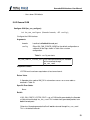
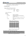
Find Devices (km_find_devices)
int km_find_devices (int num_ports,
u16 *ports);
Get a list of ports through which Komodo devices can be accessed.
Arguments
num_ports
maximum number of ports to return
ports
array into which the port numbers are returned
Return Value
This function returns the number of ports found, regardless of the array size.
Specific Error Codes
None.
26
Komodo CAN Interface User Manual
Details
Each element of the array is written with the port number.
Each Komodo device has two separate virtual ports. Each port represents a single
element in the ports array. The ports from a single Komodo device always appear
sequentially in the ports array.
Ports that are in use are OR'ed with KM_PORT_NOT_FREE ( 0x8000 ).
Examples:
Three Komodo devices are attached.
Both ports from device 0 are in-use. Both ports from the device 1 are free. The first
port from device 2 is in-use and second port is free.
array => { 0x8000, 0x8001, 0x0002, 0x0003, 0x8004, 0x0005 }
If the input array is NULL, it is not filled with any values.
If there are more ports than the array size (as specified by num_ports ), only the
first num_ports port numbers will be written into the array.
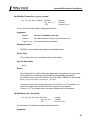
Find Devices (km_find_devices_ext)
int km_find_devices_ext (int
u16
int
u32
num_ports,
*ports,
num_ids,
*unique_ids);
Get a list of ports, and corresponding unique IDs, through which Komodo devices can be
accessed.
Arguments
num_ports
maximum number of ports to return
ports
array into which the port numbers are returned
num_ids
maximum number of unique IDs to return
unique_ids
array into which the unique IDs are returned
Return Value
This function returns the number of ports found, regardless of the array size.
27
Komodo CAN Interface User Manual
Specific Error Codes
None.
Details
This function is the same as km_find_devices() except that is also returns the
unique IDs of each Komodo port. Both ports on a physical Komodo device share the
same ID. The IDs are guaranteed to be non-zero if valid.
The IDs are the unsigned integer representation of the 10-digit serial numbers.
The number of ports and IDs returned in each of their respective arrays is
determined by the minimum of num_ports and num_ids. However, if either array
is NULL, the length passed in for the other array is used as-is, and the NULL array is
not populated. If both arrays are NULL, neither array is populated, but the number of
devices found is still returned.
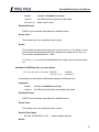
Open a Komodo port (km_open)
Komodo km_open (int port_number);
Open a Komodo port.
Arguments
port_number
The port is the same as the one obtained from function
km_find_devices. It is a zero-based number.
Return Value
This function returns a Komodo handle, which is guaranteed to be greater than zero
if valid.
Specific Error Codes
KM_UNABLE_TO_OPEN
The specified port is not associated with a
Komodo device or the port is already in
use.
KM_INCOMPATIBLE_DEVICE
There is a version mismatch between the
DLL and the firmware. The DLL is not of a
sufficient version for interoperability with the
firmware version or vice versa. See
km_open_ext() for more information.
Details
28
Komodo CAN Interface User Manual
This function is recommended for use in simple applications where extended
information is not required. For more complex applications, the use of
km_open_ext() is recommended.
Open a Komodo port (km_open_ext)
Komodo km_open_ext (int port_number, KomodoExt *km_ext);
Open a Komodo port, returning extended information in the supplied structure.
Arguments
port_number
same as km_open
km_ext
pointer to a pre-allocated structure for extended
version information available on open
Return Value
This function returns a Komodo handle, which is guaranteed to be greater than zero
if valid.
Specific Error Codes
KM_UNABLE_TO_OPEN
The specified port is not associated with a
Komodo device or the port is already in
use.
KM_INCOMPATIBLE_DEVICE
There is a version mismatch between the
DLL and the firmware. The DLL is not of a
sufficient version for interoperability with the
firmware version or vice versa. The version
information will be available in the memory
pointed to by km_ext.
Details
If 0 is passed as the pointer to the structure, this function will behave exactly like
km_open().
The KomodoExt structure is described below:
struct KomodoExt {
KomodoVersion version;
/* Features of this device. */
int
features;
29
Komodo CAN Interface User Manual
}
The features field denotes the capabilities of the Komodo port. See the API function
km_features for more information.
The KomodoVersion structure describes the various version dependencies of
Komodo components. It can be used to determine which component caused an
incompatibility error.
struct KomodoVersion {
/* Software, firmware, and hardware versions. */
u16 software;
u16 firmware;
u16 hardware;
/* Firmware revisions that are compatible with this
* software version. The top 16 bits gives the maximum
* accepted fw revision. The lower 16 bits gives the
* minimum accepted fw revision.
*/
u32 fw_revs_for_sw
/* Hardware revisions that are compatible with this
* software version. The top 16 bits gives the maximum
* accepted hw revision. The lower 16 bits gives the
* minimum accepted hw revision.
*/
u32 hw_revs_for_sw
/* Software requires that the API interface must
* be >= this version.
*/
u16 api_req_by_sw
};
All version numbers are of the format:
(major << 8) | minor
example: v1.20 would be encoded as 0x0114.
The structure is zeroed before the open is attempted. It is filled with whatever
information is available. For example, if the firmware version is not filled, then the
device could not be queried for its version number.
30
Komodo CAN Interface User Manual
This function is recommended for use in complex applications where extended
information is required. For simpler applications, the use of km_open() is
recommended.
Close a Komodo port (km_close)
int km_close (Komodo komodo);
Close a Komodo port.
Arguments
komodo
handle of a Komodo port to be closed
Return Value
The number of ports closed is returned on success. This will usually be 1.
Specific Error Codes
None.
Details
If the handle argument is zero, the function will attempt to close all possible
handles, thereby closing all open Komodo ports. The total number of Komodo ports
closed is returned by the function.
Get Supported Features (km_features)
int km_features (Komodo komodo);
Return the set of features supported by this port.
Arguments
komodo
handle of a Komodo port
Return Value
A mask of all features supported by the port is returned. Bitmask values are as
defined in Table 6.
Specific Error Codes
None.
Details
31
Komodo CAN Interface User Manual
The features mask returned by this function does not encode any information about
the features currently available for use, or currently acquired by the port. The
bitmask value only indicates the features that are supported by the port.
Get Unique ID (km_unique_id)
u32 km_unique_id (Komodo komodo);
Return the unique ID of the given Komodo port.
Arguments
komodo
handle of a Komodo port
Return Value
This function returns the unique ID for this Komodo interface. The IDs are
guaranteed to be non-zero if valid. The ID is the unsigned integer representation of
the 10-digit serial number.
Specific Error Codes
None.
Details
None.
Status String (km_status_string)
const char *km_status_string (int status);
Return the status string for the given status code.
Arguments
status
status code returned by a Komodo API function
Return Value
This function returns a human readable string that corresponds to status. If the code
is not valid, it returns a NULL string.
Specific Error Codes
None.
Details
32
Komodo CAN Interface User Manual
None.
Version (km_version)
int km_version (Komodo komodo, KomodoVersion *version);
Return the version matrix for the port associated with the given handle.
Arguments
komodo
handle of a Komodo port
version
pointer to pre-allocated structure
Return Value
A Komodo status code of KM_OK is returned on success or an error code as
detailed in Table 23.
Specific Error Codes
None.
Details
If the handle is 0 or invalid, only the software version is set.
See the details of km_open_ext for the definition of KomodoVersion.
Sleep (km_sleep_ms)
u32 km_sleep_ms (u32 milliseconds);
Sleep for given amount of time.
Arguments
milliseconds
number of milliseconds to sleep
Return Value
This function returns the number of milliseconds slept.
Specific Error Codes
None.
Details
33
Komodo CAN Interface User Manual
This function provides a convenient cross-platform function to sleep the current
thread using standard operating system functions.
The accuracy of this function depends on the operating system scheduler. This
function will return the number of milliseconds that were actually slept.
Acquire Features (km_acquire)
int km_acquire (Komodo komodo, u32 features);
Acquire features from the Komodo device.
Arguments
komodo
handle of a disabled Komodo port
features
bitmask of features to acquire as detailed in Table 6.
Return Value
A mask of all features acquired by the port is returned.
Specific Error Codes
None.
Details
The behavior of km_acquire is additive. Previously acquired features are never
released by a call to km_acquire. Thus, it is possible to acquire various features
through separate calls to km_acquire, though it is not necessary to do so.
Acquired features can be queried using a call to km_acquire with a features
value of 0.
In the event that a specified feature cannot be acquired, an error will not occur.
Instead, the returned feature mask will indicate which features are currently
acquired.
34
Komodo CAN Interface User Manual
Note: Both ports on a single Komodo can simultaneously possess the same
CONTROL and LISTEN features. The CONFIG features can only be possessed by
one port at a time.
Release Features (km_release)
int km_release (Komodo komodo, u32 features);
Release features to the Komodo device.
Arguments
komodo
handle of a disabled Komodo port
features
bitmask of features to release as detailed in Table 6.
Return Value
A mask of all features acquired by the port is returned.
Specific Error Codes
None.
Details
The behavior of km_release is subtractive. Previously acquired features are never
released by a call to km_release unless they are specified in the features mask.
Thus, it is possible to release various features through separate calls to
km_release, though it is not necessary to do so.
Acquired features can be queried using a call to km_release with a features
value of 0.
In the event that a specified feature cannot be released, an error will not occur.
Instead, the returned feature mask will indicate which features are currently
acquired.
Query Samplerate (km_get_samplerate)
int km_get_samplerate (Komodo komodo);
Query the Komodo device sampling rate.
Arguments
komodo
handle of a disabled Komodo port
35
Komodo CAN Interface User Manual
Required Features
The current samplerate in Hz is returned.
Specific Error Codes
None.
Details
None.
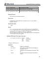
Set Komodo Timeout (km_timeout)
int km_timeout (Komodo komodo, u32 timeout_ms);
Set the read timeout to the specified number of milliseconds.
Arguments
komodo
handle of a disabled Komodo port
timeout_ms
timeout value in milliseconds, or a special enumerated
value, as shown in Table 7
Table 7 : timeout_ms enumerated types
KM_TIMEOUT_IMMEDIATE Return immediately
KM_TIMEOUT_INFINITE
Block indefinitely until data is received
Required Features
LISTEN must have been acquired on at least one feature.
Return Value
A Komodo status code of KM_OK is returned on success or an error code as
detailed in Table 23.
Specific Error Codes
None.
Details
This function sets the amount of time that km_can_read will wait before returning if
the bus is idle. If km_can_read is called and there has been no new data on the
36
Komodo CAN Interface User Manual
bus for the specified timeout interval, the function will return with the
KM_READ_TIMEOUT flag of the status value set.
If the timeout is set to KM_TIMEOUT_IMMEDIATE, calls to km_can_read will
always return immediately.
If the timeout is set to KM_TIMEOUT_INFINITE, calls to km_can_read will block
indefinitely until the Komodo port receives data from the CAN bus, or detects a
GPIO event.
Calls to km_can_read are OS dependent, and thus the supplied timeout value
cannot be guaranteed by the API.
Set Komodo Latency (km_latency)
int km_latency (Komodo komodo, u32 latency_ms);
Set the maximum latency to the specified number of milliseconds.
Arguments
komodo
handle of a disabled Komodo port
latency_ms
latency value in milliseconds
Required Features
LISTEN must have been acquired on at least one feature.
Return Value
A Komodo status code of KM_OK is returned on success or an error code as
detailed in Table 23.
Specific Error Codes
None.
Details
Set the capture latency to the specified number of milliseconds.
The capture latency effectively splits up the total amount of buffering into smaller
individual buffers. Only once one of these individual buffers is filled, does the read
function return. Therefore, in order to fulfill shorter latency requirements, these
individual buffers are set to a smaller size. If a larger latency is requested, then the
individual buffers will be set to a larger size.
37
Komodo CAN Interface User Manual
Setting a small latency can increase the responsiveness of the read function. It is
important to keep in mind that there is a fixed cost to processing each individual
buffer that is independent of buffer size. Therefore, the trade-off is that using a small
latency will increase the overhead per byte buffered. A large latency setting
decreases that overhead, but increases the amount of time that the library must wait
for each buffer to fill before the library can process their contents.
This setting is distinctly different from the timeout setting. The latency time should
be set to a value shorter than the timeout.
5.6 CAN Interface
5.6.1 CAN Notes
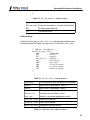
1. The Komodo CAN Duo supports two CAN channels. Some CAN API functions
require a CAN channel with an enumerated type of km_can_ch_t. This
enumerated type is described in Table 8.
Table 8 : CAN Channel Enumerated Type
KM_CAN_CH_A CAN Channel A
KM_CAN_CH_B CAN Channel B
For the Komodo CAN Solo, the channel should always be KM_CAN_CH_A for all
CAN API functions requiring it.
2. The Komodo has a limited buffer used to buffer CAN packets and CAN events. If
this buffer is filled, the Komodo will not report new packets or events, and it will
stop transmitted packes on the CAN bus. This situation can be detected by seeing
a KM_READ_END_OF_CAPTURE in the status field of the km_can_info_t struct
from the km_can_read function. Also, in this situation the CAN write functions
will return with an error code of KM_CAN_SEND_FAIL.
To decrease the possibility of this buffer filling, the following steps may be taken:
◦ Ensure the CAN bus is properly terminated, otherwise the Komodo is
saturated with CAN errors.
◦ Use only one port on the Komodo device.
◦ Use only one CAN channel on the Komodo device.
38
Komodo CAN Interface User Manual
◦ Use a lower CAN bitrate.
5.6.2 General CAN
Configure CAN (km_can_configure)
int km_can_configure (Komodo komodo, u32 config);
Configure the CAN interface.
Arguments
komodo
handle of a disabled Komodo port
config
Either KM_CAN_CONFIG_NONE for the default configuration or
a bitmask of the flags shown in Table 9 for a custom
configuration.
Table 9 : config constants
KM_CAN_CONFIG_LISTEN_SELF CAN traffic generated by the Komodo
will be returned through
km_can_read.
Required Features
LISTEN must have been acquired on at least one channel.
Return Value
A Komodo status code of KM_OK is returned on success or an error code as
detailed in Table 23.
Specific Error Codes
None.
Details
If KM_CAN_CONFIG_LISTEN_SELF is set, all CAN traffic generated by the Komodo
will be returned through km_can_read. This includes host-generated packets from
both Komodo ports.
Otherwise, Komodo-generated traffic will not be returned through km_can_read.
This is the default behavior.
39
Komodo CAN Interface User Manual
Set CAN Bus Timeout (km_can_bus_timeout)
int km_can_bus_timeout (Komodo
km_can_ch_t
u16
komodo,
channel,
timeout_ms);
Set the timeout for CAN packets awaiting transmission.
Arguments
komodo
handle of a disabled Komodo port
channel
the CAN channel for which to set the timeout value
timeout_ms
the timeout value in milliseconds
Required Features
CONTROL must have been acquired on the selected channel.
Return Value
The function returns the new timeout value in milliseconds.
Specific Error Codes
None.
Details
The timeout timer for a CAN submission begins when the packet is first given to the
CAN controller on the Komodo. If the timeout is reached before the packet is
transmitted successfully on the CAN bus, KM_CAN_SEND_TIMEOUT will be returned
by km_can_write or km_can_async_collect.
The actual timeout value will not always be set to timeout_ms. The timeout is set
to the closest permissible timeout value that is greater than or equal to
timeout_ms. This function returns the actual timeout value in milliseconds.
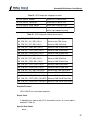
Set CAN Bitrate (km_can_bitrate)
int km_can_bitrate (Komodo
km_can_ch_t
u32
komodo,
channel,
bitrate_hz);
Set the bitrate for CAN packet reception and transmission.
Arguments
40
Komodo CAN Interface User Manual
komodo
handle of a disabled Komodo port
channel
the CAN channel for which to set the bitrate
bitrate_hz
bitrate value in hertz
Required Features
CONFIG must have been acquired on the selected channel.
Return Value
The function returns the new bitrate value in hertz.
Details
The actual bitrate value will not always be set to bitrate_hz. The bitrate is set to
the closest permissible bitrate value that is greater than or equal to bitrate_hz.
The maximum allowable bitrate is 1 MHz.
If bitrate_hz is set to 0, the Komodo device will simply return the current bitrate
set.
Auto-detect CAN Bitrate (km_can_auto_bitrate)
int km_can_auto_bitrate (Komodo
km_can_ch_t
komodo,
channel);
Automatically set the bitrate for CAN packet reception and transmission.
Arguments
komodo
handle of a disabled Komodo port
channel
the CAN channel for which to auto-detect the bitrate
Required Features
CONFIG must have been acquired on the selected channel.
Return Value
The function returns the new bitrate value in hertz.
Specific Error Codes
KM_CAN_AUTOBITRATE_FAIL
Unable to detect a bitrate.
Details
41
Komodo CAN Interface User Manual
This function provides an easy mechanism for auto-detecting the bitrate. It is
equivalent to calling km_can_auto_bitrate_ext with the following bitrates:
• 1000000
• 500000
• 250000
• 125000
• 100000
• 50000
• 25000
• 20000
Auto-detect CAN Bitrate Extended (km_can_auto_bitrate_ext)
int km_can_auto_bitrate_ext (Komodo
km_can_ch_t
u32
u32
komodo,
channel,
num_bitrate_hz,
*bitrates_hz);
Automatically set the bitrate for CAN packet reception and transmission with extended
options.
Arguments
komodo
handle of a disabled Komodo port
channel
the CAN channel for which to auto-detect the bitrate
num_bitrates_hz
number of items in the bitrate_hz array
bitrates_hz
list of bitrates
Required Features
CONFIG must have been acquired on the selected channel.
Return Value
The function returns the new bitrate value in hertz.
Specific Error Codes
KM_CAN_AUTOBITRATE_FAIL
Unable to detect a bitrate.
42
Komodo CAN Interface User Manual
Details
This function takes in a list of potential bitrates on the bus. It will attempt each bitrate
in order for up to 500 ms before attempting a new bitrate. If a successfully
completed packet is perceived by the channel, then that bitrate is deemed a
success, and the bitrate is returned.
If the function is unable to find a successful packet for any of the bitrates within the
alotted time, it will return KM_CAN_AUTOBITRATE_FAIL.
The actual bitrate value will not always be set to the values in bitrates_hz. The
bitrate is set to the closest permissible bitrate value that is greater than or equal to
the value in bitrates_hz. The maximum allowable bitrate is 1 MHz.
Set Target Power (km_can_target_power)
int km_can_target_power (Komodo
km_can_ch_t
km_power_t
komodo,
channel,
power);
Set the target power option on a CAN channel.
Arguments
komodo
handle of a disabled Komodo port
channel
the CAN channel for which to set target power
power
the desired power setting, as described in Table 10
Table 10 : power enumerated types
KM_TARGET_POWER_OFF
Disable target power.
KM_TARGET_POWER_ON
Enable target power.
KM_TARGET_POWER_QUERY Query target power.
Required Features
CONFIG must have been acquired on the supplied channel.
Return Value
The current state of the target power pin on the supplied CAN channel will be
returned. The configuration will be described by the same values as in the table
above.
43
Komodo CAN Interface User Manual
Specific Error Codes
None.
Details
None.
Port Enable (km_enable)
int km_enable (Komodo komodo);
Enable the port associated with the provided handle.
Arguments
komodo
handle of a disabled Komodo port
Required Features
Either LISTEN or CONTROL must have been acquired on at least one feature.
Return Value
A Komodo status code of KM_OK is returned on success or an error code as
detailed in Table 23.
Specific Error Codes
None.
Details
This function enables LISTEN and CONTROL features acquired by the provided port.
The port must have acquired at least one of these features, and must not be active
prior to calling km_enable.
If another port on the Komodo device is active with only the CAN LISTEN feature,
and this port has the CAN CONTROL feature, then the other port may experience
brief packet loss when this port is enabled, and the CAN channel is changed to an
active participant on the bus.
Port Disable (km_disable)
int km_disable (Komodo komodo);
Disable the port associated with the provided handle.
44
Komodo CAN Interface User Manual
Arguments
komodo
handle of an enabled Komodo port
Required Features
None.
Return Value
A Komodo status code of KM_OK is returned on success or an error code as
detailed in Table 23.
Specific Error Codes
None.
Details
This function disables active LISTEN and CONTROL functionality on the provided
port. The port must be active prior to calling km_disable.
If another port on the Komodo device is active with only the CAN LISTEN feature,
and this port has the CAN CONTROL feature, then the other port may experience
brief packet loss when this port is disabled, and the CAN channel is reverted to
listen-only mode.
Query CAN Bus State (km_can_query_bus_state)
int km_can_bus_state (Komodo
km_can_ch_t
u08
u08
u08
komodo,
channel,
*bus_state,
*rx_error,
*tx_error);
Query the current state of the provided CAN channel.
Arguments
komodo
handle of an enabled Komodo port
channel
the CAN channel for which to query error counters
bus_state
filled with the current CAN state enumerated value as
shown in Table 11
rx_error
filled with the total number of CAN RX errors
tx_error
filled with the total number of CAN TX errors
45
Komodo CAN Interface User Manual
Table 11 : bus_state enumerated types
KM_CAN_BUS_STATE_LISTEN_ONLY Listen only mode
KM_CAN_BUS_STATE_CONTROL
Control mode
KM_CAN_BUS_STATE_WARNING
Warning state
KM_CAN_BUS_STATE_ACTIVE
Active error state
KM_CAN_BUS_STATE_PASSIVE
Passive error state
KM_CAN_BUS_STATE_OFF
Bus-off condition
Required Features
Either CONFIG or LISTEN must have been acquired on the selected channel.
Return Value
A Komodo status code of KM_OK is returned on success or an error code as
detailed in Table 23.
Specific Error Codes
None.
Details
Queries the provided CAN channels controller for its state and its error counts.
CAN Read (km_can_read)
int km_can_read (Komodo
km_can_info_t
km_can_packet_t
int
u08
komodo,
*info,
*packet,
num_bytes,
*data);
Read a packet or info from a Komodo port.
Arguments
komodo
handle of an enabled Komodo port
info
filled with CAN bus information along with status and events
packet
filled with CAN packet parameters
num_bytes
length of the data array
data
an allocated array of u08 which is filled with the received data
46
Komodo CAN Interface User Manual
Required Features
LISTEN must have been acquired for at least one feature.
Return Value
A Komodo status code of KM_OK is returned on success or an error code as
detailed in Table 23.
Specific Error Codes
KM_READ_EMPTY
No data was available for a non-blocking call.
Details
Timeouts
The timeout value for km_can_read is configurable using km_timeout. The
km_timeout function sets the amount of time that km_can_read will block before
returning if the bus is idle.
If km_can_read is called and there has been no new data on the bus for the
specified timeout interval, the function will return with the KM_READ_TIMEOUT flag
of the status value set. An exception to this exists if info is a NULL pointer. In this
case, the function returns KM_OK.
If the timeout value is set to KM_TIMEOUT_IMMEDIATE, this function is nonblocking. If no data is immediately available, the function returns
KM_CAN_READ_EMPTY.
If the timeout value is set to KM_TIMEOUT_INFINITE, this function will block
indefinitely until the Komodo port receives data on the CAN bus or a GPIO event.
CAN Packet Struct
A CAN packet struct type, km_can_packet_t, is used to provide information about
the CAN packet received on the bus on calls to km_can_read. This same struct is
used for the CAN transmit functions.
struct km_can_packet_t {
u08
remote_req;
u08
extend_addr;
u08
dlc;
u32
id;
47
Komodo CAN Interface User Manual
};
Table 12 : km_can_packet_t field descriptions
remote_req
A flag set if the packet is a remote frame.
extend_addr A flag set if the packet is using the 29 bit identifier.
dlc
The data length code field.
id
The identifier field.
CAN Info Struct
A CAN info struct type, km_can_info_t, is used to provide important meta
information about the CAN bus or other events, on calls to km_can_read.
/* CAN bus information */
struct km_can_info_t {
u64
timestamp;
u32
status;
u32
events;
km_can_ch_t
channel;
u32
bitrate_hz;
u08
host_gen;
u08
rx_error_count;
u08
tx_error_count;
u32
overflow_count;
};
Table 13 : km_can_info_t field descriptions
timestamp
The timestamp of when the packet or event began
status
Status mask as described in Table 14
events
Event mask as described in Table 15
channel
The channel on which the packet or event occurred
bitrate_hz
The bitrate of the CAN bus in hertz
host_gen
Indicates a host generated packet or event
rx_error_count CAN RX error counter
tx_error_count CAN TX error counter
overflow_count Read queue overflow counter
Table 14 : CAN Read status code descriptions
48
Komodo CAN Interface User Manual
KM_READ_TIMEOUT
The read timeout limit was
reached
KM_READ_ERR_OVERFLOW
Packet loss due to
insufficient read rate
KM_READ_END_OF_CAPTURE
Capture ended
Status Codes for CAN Errors
KM_READ_CAN_ERR
CAN Error has occurred
KM_READ_CAN_ERR_FULL_MASK
A bitmask for the entire
CAN error
Status Codes for CAN Error Position
KM_READ_CAN_ERR_POS_MASK
A bitmask for the position
of the error
KM_READ_CAN_ERR_POS_SOF
Error at the Start of Frame
KM_READ_CAN_ERR_POS_ID28_21
Error at ID28 - ID21 bits
KM_READ_CAN_ERR_POS_ID20_18
Error at ID20 - ID18 bits
KM_READ_CAN_ERR_POS_SRTR
Error at the SRTR bit
KM_READ_CAN_ERR_POS_IDE
Error at the IDE bit
KM_READ_CAN_ERR_POS_ID17_13
Error at ID17 - ID13 bits
KM_READ_CAN_ERR_POS_ID12_5
Error at the ID12 - ID5 bits
KM_READ_CAN_ERR_POS_ID4_0
Error at the ID4 - ID0 bits
KM_READ_CAN_ERR_POS_RTR
Error at the RTR bit
KM_READ_CAN_ERR_POS_RSVD_1
Error at Reserved Bit 1
KM_READ_CAN_ERR_POS_RSVD_0
Error at Reserved Bit 0
KM_READ_CAN_ERR_POS_DLC
Error at the Data Length
Code
KM_READ_CAN_ERR_POS_DF
Error at the Data Field
KM_READ_CAN_ERR_POS_CRC_SEQ
Error at the CRC
Seqeuence
KM_READ_CAN_ERR_POS_CRC_DEL
Error at the CRC Delimiter
KM_READ_CAN_ERR_POS_ACK_SLOT
Error at the Acknowledge
Slot
KM_READ_CAN_ERR_POS_ACK_DEL
Error at the Acknowledge
Delimiter
KM_READ_CAN_ERR_POS_EOF
Error at the End of Frame
KM_READ_CAN_ERR_POS_INTRMSN
Error at the Intermission
49
Komodo CAN Interface User Manual
KM_READ_CAN_ERR_POS_AEF
Error at the Active Error
Flag
KM_READ_CAN_ERR_POS_PEF
Error at the Passive Error
Flag
KM_READ_CAN_ERR_POS_TDB
Error at the Tolerate
Dominant Bits
KM_READ_CAN_ERR_POS_ERR_DEL
Error at the Error Delimiter
KM_READ_CAN_ERR_POS_ERR_OVRFLG
Error at the Overload Flag
Status Codes for CAN Error Direction
KM_READ_CAN_ERR_DIR_MASK
A bit mask for the direction
of the error
KM_READ_CAN_ERR_DIR_TX
Error during transmission.
KM_READ_CAN_ERR_DIR_RX
Error during reception.
Status Codes for CAN Error Type
KM_READ_CAN_ERR_TYPE_MASK
A bit mask for the type of
the error
KM_READ_CAN_ERR_TYPE_BIT
Bit type error
KM_READ_CAN_ERR_TYPE_FORM
Form type error
KM_READ_CAN_ERR_TYPE_STUFF
Stuff type error
KM_READ_CAN_ERR_TYPE_OTHER
Other type error
Status Codes for CAN Arbitration Loss
KM_READ_CAN_ARB_LOST
CAN controller lost
arbitration
KM_READ_CAN_ARB_LOST_POS_MASK
Mask to determine the
position of arbitration loss
Table 15 : CAN Read event code descriptions
KM_EVENT_DIGITAL_INPUT
Digital input detected
KM_EVENT_DIGITAL_INPUT_MASK
Digital input bit mask
KM_EVENT_DIGITAL_INPUT_N
Digital input detected on pin N
KM_EVENT_CAN_BUS_STATE_LISTEN_ONLY Entered Listen Mode
KM_EVENT_CAN_BUS_STATE_CONTROL
Entered Control Mode
KM_EVENT_CAN_BUS_STATE_WARNING
Reached Warning State
KM_EVENT_CAN_BUS_STATE_ACTIVE
Entered Active Error Mode
KM_EVENT_CAN_BUS_STATE_PASSIVE
Entered Passive Error Mode
KM_EVENT_CAN_BUS_STATE_OFF
Inactive state entered
50
Komodo CAN Interface User Manual
KM_EVENT_CAN_BUS_BITRATE
Bitrate update event
Asynchronous CAN Submit (km_can_async_submit)
int km_can_async_submit (Komodo
km_can_ch_t
u08
const km_can_packet_t
int
const u08
komodo,
channel,
flags,
*packet,
num_bytes,
*data);
Asynchronously submit a CAN packet.
Arguments
komodo
handle of an enabled Komodo port
channel
the CAN channel on which to submit the packet
flags
special operations as described in Table 16
packet
pre-allocated structure containing CAN packet
parameters, see Table 12
num_bytes
size of the data array
data
pre-allocated array containing CAN packet data
Table 16 : flags enumerated types
KM_CAN_FLAGS_ONE_SHOT Only attempt to transmit the packet once. Do not retransmit.
Required Features
CONTROL must have been acquired on the selected channel.
Return Value
A Komodo status code of KM_OK is returned on success or an error code as
detailed in Table 23.
Specific Error Codes
KM_CAN_ASYNC_MAX_REACHED
There are too many
outstanding CAN packets
Details
51
Komodo CAN Interface User Manual
This function asynchronously submits a CAN packet to the Komodo port for
transmission on the CAN bus. As an asynchrnonous call, this function will not block.
If the KM_CAN_FLAGS_ONE_SHOT bit is set in flags, the packet will be sent as a
one-shot transmission. Only one attempt will be made to transmit the packet on the
CAN bus in this case.
The response to an asynchronous CAN submission should be collected with a call
to km_can_async_collect.
Asynchronous CAN Collect (km_can_async_collect)
int km_can_async_collect (Komodo
u32
u32
komodo,
timeout_ms,
*arbitration_count);
Collect the response to a previously submitted CAN packet.
Arguments
komodo
handle of an enabled Komodo port
timeout_ms
timeout value
arbitration_count
filled with the number of packets lost
because of arbitration loss
Required Features
None.
Return Value
A Komodo status code of KM_OK is returned on success or an error code as
detailed in Table 23.
Specific Error Codes
KM_CAN_ASYNC_EMPTY
There are no submitted CAN packets
KM_CAN_ASYNC_TIMEOUT
The function timed out waiting for a response
KM_CAN_SEND_TIMEOUT
The packet timedout
KM_CAN_SEND_FAIL
Transmission failed
Details
52
Komodo CAN Interface User Manual
This function blocks for up to timeout_ms until a response is available for
collection from the port. If a successful response is collected, KM_OK is returned. If
the submitted packet timed out, KM_CAN_SEND_TIMEOUT is returned.
If the internal buffer on the Komodo device is overflowed KM_CAN_SEND_FAIL is
returned. This error will be returned until the Komodo device is disabled.
The arbitration_count field is set based on the number of arbitration errors
observed before the CAN packet timed out, or was transmitted successfully.
If the timeout_ms value is reached before any response is collected from the port,
the function will return KM_CAN_ASYNC_TIMEOUT.
CAN Write (km_can_write)
int km_can_write (Komodo
km_can_ch_t
u08
const km_can_packet_t
int
const u08
u32
komodo,
channel,
flags,
*packet,
num_bytes,
*data,
*arbitration_count);
Issue a packet to be transmitted on the CAN bus, and block until a response is recieved.
Arguments
komodo
handle to an enabled Komodo port
channel
the CAN channel on which to submit the
packet
flags
See flag field as described in Section
5.6.2.11
packet
pre-allocated structure containing CAN
packet parameters
num_bytes
size of the data array
data
pre-allocated array containing CAN packet
data
arbitration_count
filled with the number of transmissions
failed due to arbitration loss
Required Features
CONTROL must have been acquired on the selected channel.
53
Komodo CAN Interface User Manual
Return Value
A Komodo status code of KM_OK is returned on success or an error code as
detailed in Table 23.
Specific Error Codes
KM_CAN_ASYNC_PENDING
Uncollected asynchronously submitted
packets must be collected
Details
This function simply acts as a wrapper for the asynchronous submit and collect
functions.
km_can_async_submit(komodo, channel, flags,
packet, num_bytes, data);
km_can_async_collect(komodo, KM_TIMEOUT_INFINITE,
arbitration_count);
The CAN packet is submitted asynchronously, and km_can_async_collect is
called with KM_TIMEOUT_INFINITE to block indefinitely until a response is
received.
A KM_CAN_ASYNC_PENDING error is returned if there are any uncollected
asynchronously submitted packets. Packets submitted with
km_can_async_submit should always be collected using
km_can_async_collect.
5.7 GPIO Interface
5.7.1 GPIO Notes
1. When the GPIO pin is configured as an input, the input change event reporting is
limited to one edge transition every 20 us across all pins.
54
Komodo CAN Interface User Manual
2. When the GPIO pin is configured as an output controlled by a CAN bus event, the
pin will toggle with a pulse duration of about 200 ns.
5.7.2 GPIO Interface
Configure GPIO Input Pin (km_gpio_config_in)
int km_gpio_config_in (Komodo
u08
u08
u08
komodo,
pin_number,
bias,
trigger);
Configure a GPIO input pin.
Arguments
komodo
handle of a Komodo port
pin_number
GPIO input pin configuration enumerated type, as
described in Table 17
bias
voltage bias enumerated type, as described in Table
18
trigger
trigger condition enumerated type, as described in
Table 19
Table 17 : GPIO pin configuration values
KM_GPIO_PIN_1_CONFIG GPIO Pin 1
KM_GPIO_PIN_2_CONFIG GPIO Pin 2
KM_GPIO_PIN_3_CONFIG GPIO Pin 3
KM_GPIO_PIN_4_CONFIG GPIO Pin 4
KM_GPIO_PIN_5_CONFIG GPIO Pin 5
KM_GPIO_PIN_6_CONFIG GPIO Pin 6
KM_GPIO_PIN_7_CONFIG GPIO Pin 7
KM_GPIO_PIN_8_CONFIG GPIO Pin 8
Table 18 : GPIO input pin voltage bias values
KM_PIN_BIAS_TRISTATE No modification to input voltage
KM_PIN_BIAS_PULLUP
Pulls up input voltage using high impedance resistor to 3.3 V
KM_PIN_BIAS_PULLDOWN Pulls down input voltage using high impedance resistor to GND
Table 19 : GPIO input pin trigger condition values
55
Komodo CAN Interface User Manual
KM_PIN_TRIGGER_NONE
Do not report pin changes
KM_PIN_TRIGGER_RISING_EDGE
Report change on a rising input edge
KM_PIN_TRIGGER_FALLING_EDGE Report change on a falling input edge
KM_PIN_TRIGGER_BOTH_EDGES
Report change on either a rising or falling input edge
Required Features
GPIO CONFIG must have been acquired.
Return Value
A Komodo status code of KM_OK is returned on success or an error code as
detailed in Table 23.
Specific Error Codes
None.
Details
The trigger parameter defines when an input change event is reported by the
km_can_read function and is not related to triggering the Komodo interface to start
collecting data. As an example, if an input pin is configured to
KM_PIN_TRIGGER_FALLING_EDGE, an input change event will only be reported on
the falling edge and not the rising edge.
Configure GPIO Output Pin (km_gpio_config_out)
int km_gpio_config_out (Komodo
u08
u08
u08
komodo,
pin_number,
drive,
source);
Configure a GPIO output pin.
Arguments
komodo
handle of a Komodo port
pin_number
GPIO output pin configuration enumerated type, as
described in Table 17
drive
voltage drive enumerated type as described in Table
20
source
pin control source enumerate type as described in
Table 21
56
Komodo CAN Interface User Manual
Table 20 : GPIO output pin voltage drive values
KM_PIN_DRIVE_NORMAL
Active 3.3 V; Inactive GND
KM_PIN_DRIVE_INVERTED
Active GND; Inactive 3.3 V
KM_PIN_DRIVE_OPEN_DRAIN
Active GND; Inactive FLOAT
KM_PIN_DRIVE_OPEN_DRAIN_PULLUP Equivalent to KM_PIN_OPEN_DRAIN
with a high impedance pullup
Table 21 : GPIO output pin control source values
KM_PIN_SRC_SOFTWARE_CTL
Controlled using km_gpio_set.
KM_PIN_SRC_ALL_ERR_CAN_A
Active on any CAN A error
KM_PIN_SRC_BIT_ERR_CAN_A
Active on CAN A Bit Error
KM_PIN_SRC_FORM_ERR_CAN_A
Active on CAN A Form Error
KM_PIN_SRC_STUFF_ERR_CAN_A
Active on CAN A Stuff Error
KM_PIN_SRC_OTHER_ERR_CAN_A
Active on CAN A Other Error
KM_PIN_SRC_ALL_ERR_CAN_B
Active on any CAN B error
KM_PIN_SRC_BIT_ERR_CAN_B
Active on CAN B Bit Error
KM_PIN_SRC_FORM_ERR_CAN_B
Active on CAN B Form Error
KM_PIN_SRC_STUFF_ERR_CAN_B
Active on CAN B Stuff Error
KM_PIN_SRC_OTHER_ERR_CAN_B
Active on CAN B Other Error
KM_PIN_SRC_ALL_ERR_CAN_BOTH
Active on any CAN A or B error
KM_PIN_SRC_BIT_ERR_CAN_BOTH
Active on CAN A or B Bit Error
KM_PIN_SRC_FORM_ERR_CAN_BOTH
Active on CAN A or B Form Error
KM_PIN_SRC_STUFF_ERR_CAN_BOTH Active on CAN A or B Stuff Error
KM_PIN_SRC_OTHER_ERR_CAN_BOTH Active on CAN A or B Other Error
Required Features
GPIO CONFIG must have been acquired.
Return Value
A Komodo status code of KM_OK is returned on success or an error code as
detailed in Table 23.
Specific Error Codes
None.
57
Komodo CAN Interface User Manual
Details
None.
Get (km_gpio_get)
int km_gpio_get (Komodo komodo);
Get the value of current GPIO pins as a bitmask.
Arguments
komodo
handle of a Komodo port
Required Features
None.
Return Value
Returns the current value of all GPIO pins, input and output.
Specific Error Codes
None.
Details
None.
Set (km_gpio_set)
int km_gpio_set (Komodo komodo, u08 value, u08 mask);
Set the value of current GPIO outputs.
Arguments
komodo
handle of a Komodo port
value
value to which to set the pins provided in mask
mask
a bitmask specifying which outputs should be set to the
supplied value (see Table 22).
Table 22 : GPIO pin mask values
KM_GPIO_PIN_1_MASK GPIO Pin 1 Mask
58
Komodo CAN Interface User Manual
KM_GPIO_PIN_2_MASK GPIO Pin 2 Mask
KM_GPIO_PIN_3_MASK GPIO Pin 3 Mask
KM_GPIO_PIN_4_MASK GPIO Pin 4 Mask
KM_GPIO_PIN_5_MASK GPIO Pin 5 Mask
KM_GPIO_PIN_6_MASK GPIO Pin 6 Mask
KM_GPIO_PIN_7_MASK GPIO Pin 7 Mask
KM_GPIO_PIN_8_MASK GPIO Pin 8 Mask
Required Features
CONTROL must have been acquired.
Return Value
A Komodo status code of KM_OK is returned on success or an error code as
detailed in Table 23.
Specific Error Codes
None.
Details
This function sets the value of any GPIO pins configured as software controlled
outputs. Any attempts to set a pin configured as either an input or as a nonsoftware-controlled output will be silently ignored.
5.8 Error Codes
Table 23 : Komodo API Error Codes
Literal Name
KM_OK
Value km_status_string() return value
0 ok
KM_UNABLE_TO_LOAD_LIBRARY
-1 unable to load library
KM_UNABLE_TO_LOAD_DRIVER
-2 unable to load USB driver
KM_UNABLE_TO_LOAD_FUNCTION
-3 unable to load binding function
KM_INCOMPATIBLE_LIBRARY
-4 incompatible library version
KM_INCOMPATIBLE_DEVICE
-5 incompatible device version
KM_COMMUNICATION_ERROR
-6 communication error
59
Komodo CAN Interface User Manual
KM_UNABLE_TO_OPEN
-7 unable to open device
KM_UNABLE_TO_CLOSE
-8 unable to close device
KM_INVALID_HANDLE
-9 invalid device handle
KM_CONFIG_ERROR
-10 configuration error
KM_PARAM_ERROR
-11 parameter error
KM_FUNCTION_NOT_AVAILABLE
-12 function not available
KM_FEATURE_NOT_ACQUIRED
-13 necessary feature not acquired
KM_NOT_DISABLED
-14 port must be disabled
KM_NOT_ENABLED
-15 port must be enabled
KM_CAN_READ_EMPTY
-101 CAN nothing to read
KM_CAN_SEND_TIMEOUT
-102 CAN send timed out
KM_CAN_SEND_FAIL
-103 CAN send failed
KM_CAN_ASYNC_EMPTY
-104 CAN no responses available
KM_CAN_ASYNC_MAX_REACHED
-105 CAN async submit limit reached
KM_CAN_ASYNC_PENDING
-106 CAN async packets pending
KM_CAN_ASYNC_TIMEOUT
-107 CAN async collect timed out
KM_CAN_AUTO_BITRATE_FAIL
-108 Unable to detect a bitrate
60
Komodo CAN Interface User Manual
6 Legal / Contact
6.1 Disclaimer
All of the software and documentation provided in this datasheet, is copyright Total
Phase, Inc. ("Total Phase"). License is granted to the user to freely use and distribute
the software and documentation in complete and unaltered form, provided that the
purpose is to use or evaluate Total Phase products. Distribution rights do not include
public posting or mirroring on Internet websites. Only a link to the Total Phase download
area can be provided on such public websites.
Total Phase shall in no event be liable to any party for direct, indirect, special, general,
incidental, or consequential damages arising from the use of its site, the software or
documentation downloaded from its site, or any derivative works thereof, even if Total
Phase or distributors have been advised of the possibility of such damage. The software,
its documentation, and any derivative works is provided on an "as-is" basis, and thus
comes with absolutely no warranty, either express or implied. This disclaimer includes,
but is not limited to, implied warranties of merchantability, fitness for any particular
purpose, and non-infringement. Total Phase and distributors have no obligation to
provide maintenance, support, or updates.
Information in this document is subject to change without notice and should not be
construed as a commitment by Total Phase. While the information contained herein is
believed to be accurate, Total Phase assumes no responsibility for any errors and/or
omissions that may appear in this document.
6.2 Life Support Equipment Policy
Total Phase products are not authorized for use in life support devices or systems. Life
support devices or systems include, but are not limited to, surgical implants, medical
systems, and other safety-critical systems in which failure of a Total Phase product could
cause personal injury or loss of life. Should a Total Phase product be used in such an
unauthorized manner, Buyer agrees to indemnify and hold harmless Total Phase, its
officers, employees, affiliates, and distributors from any and all claims arising from such
use, even if such claim alleges that Total Phase was negligent in the design or
manufacture of its product.
6.3 Contact Information
Total Phase can be found on the Internet at http://www.totalphase.com/. If you have
support-related questions, please go to the Total Phase website. For sales inquiries,
please contact [email protected].
61
Komodo CAN Interface User Manual
©2011-2014 Total Phase, Inc.
All rights reserved.
62