1
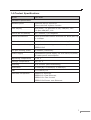
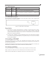
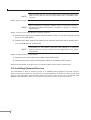
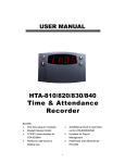
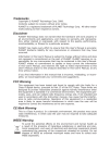
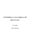
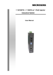
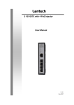
Trademarks Copyright PLANET Technology Corp. 2005. Contents subject to which revision without prior notice. PLANET is a registered trademark of PLANET Technology Corp. All other trademarks belong to their respective owners. Disclaimer PLANET Technology does not warrant that the hardware will work properly in all environments and applications, and makes no warranty and representation, either implied or expressed, with respect to the quality, performance, merchantability, or fitness for a particular purpose. PLANET has made every effort to ensure that this User’s Manual is accurate; PLANET disclaims liability for any inaccuracies or omissions that may have occurred. Information in this User’s Manual is subject to change without notice and does not represent a commitment on the part of PLANET. PLANET assumes no responsibility for any inaccuracies that may be contained in this User’s Manual. PLANET makes no commitment to update or keep current the information in this User’s Manual, and reserves the right to make improvements to this User’s Manual and/or to the products described in this User’s Manual, at any time without notice. If you find information in this manual that is incorrect, misleading, or incomplete, we would appreciate your comments and suggestions. FCC Warning This equipment has been tested and found to comply with the limits for a Class A digital device, pursuant to Part 15 of the FCC Rules. These limits are designed to provide reasonable protection against harmful interference when the equipment is operated in a commercial environment. This equipment generates, uses, and can radiate radio frequency energy and, if not installed and used in accordance with the Instruction manual, may cause harmful interference to radio communications. Operation of this equipment in a residential area is likely to cause harmful interference in which case the user will be required to correct the interference at whose own expense. CE Mark Warning This is a Class A product. In a domestic environment, this product may cause radio interference, in which case the user may be required to take adequate measures. WEEE Warning To avoid the potential effects on the environment and human health as a result of the presence of hazardous substances in electrical and electronic equipment, end users of electrical and electronic equipment should understand the meaning of the crossed-out wheeled bin symbol. Do not dispose of WEEE as unsorted municipal waste and have to collect such WEEE separately. Revision PLANET Fast Ethernet Switch with 802.3af injector built-in User’s Manual FOR MODEL: FSD-804P Rev: 1.0 Part No. 2010-A31110-000 Table of Contents Chapter 1 Introduction 1 1.1 Package Contents 1 1.2 How to Use This Manual 1 1.3 Product Features 2 1.4 Product Specifications 3 Chapter 2 Installation 5 2.1 Product Description 5 2.2 Installing a FSD-804P 6 Chapter 3 Switch Operation 3.1 Address Table 7 3.2 Learning 7 3.3 Forwarding & Filtering 7 3.4 Store-and-Forward 7 3.5 Auto-Negotiation 8 Chapter 4 Trouble Shooting APPENDIX A 9 10 A.1 Switch‘s RJ-45 Pin Assignments 10 A.2 10/100Mbps, 10/100Base-TX 10 Chapter 1 INTRODUCTION 1.1 Package Contents Open the box of the Switch and unpack it carefully. The box should contain the following items: ● The Switch ● Power Cord x 1 ● User s Manual x 1 If any item is found missing or damaged, please contact your local reseller for replacement. Please retain the carton including the original packing material, and use them against to repack the product in case there is a need to return it to us for repair. 1.2 How to Use This Manual This Ethernet Switch User Manual is structured as follows: Chapter 2 Installation This chapter explains the functions and how to physically install the FSD-804P. Chapter 3 Switch Operation This chapter explains the switch operation of FSD-804P. Chapter 4 Trouble Shooting This chapter contains troubleshooting of FSD-804P Appendices This chapter contains cable information of FSD-804P. 1.3 Product Features ● 8-Port 10/100Mbps Fast Ethernet ports ● 4-Port support 48VDC PoE power to IEEE802.3af compliant Powered Device ● Hardware based 10/100Mbps auto-negotiation ● Flow control for full duplex operation and back pressure for half duplex operation ● Integrated address look-up engine, support 2K absolute MAC addresses 1 ● Automatic address learning and address aging ● Supports Auto MDI/MDI-X function ● LED indicators for easy network diagnostic ● Comply with IEEE802.3 Ethernet, IEEE802.3u Fast Ethernet, IEEE802.3x Flow Control and IEEE802.3af Power over Ethernet ● EMI standards comply with FCC, CE class B 2 1.4 Product Specifications Model FSD-804P Hardware Specification Network ports 8-Port RJ-45 for 10/100TX 4-Port with PoE injector function LED Display One power, 1-4 port PoE in-use, LNK/ACT, 100 5-8 port LNK/ACT, 100 PoE RJ-45 Pin polarity 4/5: Positive; 7/8: Negative Switch architecture Store and forward switch architecture. Back-plan up MAC address 2K MAC address table with Auto learning function Remote power feeding End-point to 1.6Gbps insert type and compatible with IEEE802.3af Per port feeding power 15.4Watts (maximum) Power Supply Embedded AC power supply: AC 100~240V, 50/60Hz, 45 watts power consumption Operating Temperature 0~50˚C Storage Temperature -40~70˚C Humidity 10% to 90% (Non-condensing) Dimension 217mm(W) x 135mm(D) x 43mm(H) EMI FCC Class B, CE Standard Compliance IEEE802.3 Ethernet, IEEE802.3u Fast Ethernet, IEEE802.3x Flow Control IEEE802.3af Power over Ethernet. 3 Chapter 2 INSTALLATION This chapter describes the functionalities of FSD-804P’s components and guides how to install it on the desktop or shelf. Basic knowledge of networking is assumed. Please read this chapter completely before continuing. 2.1 Product Description For cost saving and flexible using of PoE power provision, half of the 10/100Mbps TP ports of FSD-804P provide PoE power injector function which is able to drive 4 IEEE802.3af compliant powered devices. For SOHO or department network, the switches also provide a Simple and cost-effective, highly reliable network connection. And is the ideal device for bridging Ethernet to Fast Ethernet workgroups or networks. Therefore, the switch will be the fast being recognized as one of the most important building blocks for today networking technology. Solidly built in small size that is easy to position when space is at a premium. Ideal for conference rooms, class rooms, study groups or small offices. Place it on any flat surface or use the included wall mount kit to tuck it out of the way. 2.1.1 Product Application Department/ Workgroup PoE Switch: Providing up to 4 PoE, in-line power interface, the switch can easily build a power centralcontrolled IP phone system, IP Camera system, AP group for the enterprise. For instance, 4 camera / AP can be easily installed around the corner in the company for surveillance demands or build a wireless roaming environment in the office. Without the power-socket limitation, the switch makes the installation of cameras or WLAN AP more easily and efficiently. 2.1.2 FSD-804P Front Panel Figure 2-1 shows the front panel of FSD-804P Figure 2-1 The front panel of FSD-804P 4 2.1.3 LED Indicators LED Color Function PWR Green Light: Power on PoE in use Green Light: The port is providing 48VDC power LNK/ACT Green Light: The port is successfully established Blink: The port is actively receiving or sending the data 100 Green Light: The port is operating at 100Mbps speed 2.1.4 FSD-804P rear panel The rear panel of the Switch indicates an AC inlet power socket, which accepts input power from 100 to 240VAC, 50/60Hz. Figure 2-2 Rear Panel of FSD-804P Power Notice: 1. The device is a power-required device, it means, it will not work till it is powered. If your networks should active all the time, please consider using UPS (Uninterrupted Power Supply) for your device. It will prevent you from network data loss or network downtime. 2. In some area, installing a surge suppression device may also help to protect your switch from being damaged by unregulated surge or current to the Switch or the power adapter. 2.2 Installing a FSD-804P This part describes how to install your FSD-804P Fast Ethernet Switch and make connections to the switch. Please read the following topics and perform the procedures in the order being presented. PLANET FSD-804P Fast Ethernet Switch do not need software configuration. To install your FSD-804P on a desktop or shelf, simply complete the following steps. 2.2.1 Desktop Installation To install a FSD-804P on a desktop or shelf, simply complete the following steps: Step1: Attach the rubber feet to the recessed areas on the bottom of the switch. Step2: Place the FSD-804P on a desktop or shelf near an AC power source. 5 NOTE: Optional rack-ear for 10-inch cabinet rack mounting (RKE-10A) and 19-inch cabinet rack mounting (RKE-10B) is available upon request. Step3: Keep enough ventilation space between the switch and the surrounding objects NOTE: When choosing a location, please keep in mind the environmental restrictions discussed in Chapter 1, Section 4, Product Specification. Step4: Connect your FSD-804P to network devices A. Connect one end of a standard network cable to the 10/100 RJ-45 ports on the front of the FSD-804P. B. Connect the other end of the cable to the network devices such as printer servers, workstations or routers etc. NOTE: Connection to the Switch requires UTP Category 5 network cabling with RJ-45 tips. Please see the Appendex A for more information. Step5: Supply power to the Switch. A. Connect one end of the power cable to the FSD-804P B. Connect the power plug of the power cable to a standard wall outlet. When the FSD-804P receives power, the Power LED should remain solid Green. 2.3 Installing Powered Devices The FSD-804P is able to support power to 4 IEEE802.3af compliant powered devices. When the powered device is connected to the FSD-804P by an Ethernet cable at the first 4 ports, the FSD-804P automatically detect the device and check if it is compliant with IEEE80.23af standard. Then run the power provision process to provide power. 6 Chapter 3 SWITCH OPERATION 3.1 Address Table The Switch is implemented with an address table. This address table composed of many entries. Each entry is used to store the address information of some node in network, including MAC address, port no, etc. This in-formation comes from the learning process of Ethernet Switch. 3.2 Learning When one packet comes in from any port, the Switch will record the source address, port no. And the other related information in address table. This information will be used to decide either forwarding or filtering for future packets. 3.3 Forwarding & Filtering When one packet comes from some port of the Ethernet Switching, it will also check the destination address besides the source address learning. The Ethernet Switching will lookup the address-table for the destination address. If not found, this packet will be forwarded to all the other ports except the port, which this packet comes in. And these ports will transmit this packet to the network it connected. If found, and the destination address is located at different port from this packet comes in, the Ethernet Switching will forward this packet to the port where this destination address is located according to the information from address table. But, if the destination address is located at the same port with this packet comes in, then this packet will be filtered. Thereby increasing the network throughput and availability. 3.4 Store-and-Forward Store-and-Forward is one type of packet-forwarding techniques. A Store-and-Forward Ethernet Switching stores the incoming frame in an internal buffer, do the complete error checking before transmission. Therefore, no error packets occurrence, it is the best choice when a network needs efficiency and stability. The Ethernet Switch scans the destination address from the packet-header, searches the routing table pro-vided for the incoming port and forwards the packet, only if required. The fast forwarding makes the switch attractive for connecting servers directly to the network, thereby increasing throughput and availability. How-ever, the switch is most commonly used to segment existence hubs, which nearly always improves overall performance. An Ethernet Switching can be easily configured in any Ethernet network environment to significantly boost bandwidth using conventional cabling and adapters. Due to the learning function of the Ethernet switching, the source address and corresponding port number of each incoming and outgoing packet are stored in a routing table. This information is subsequently used to filter packets whose destination address is on the same segment as the source address. This confines network traffic to its respective domain and reduce the overall load on the network. The Switch performs “Store and forward” therefore, no error packets occur. More reliably, it reduces the re-transmission rate. No packet loss will occur. 7 3.5 Auto-Negotiation The STP ports on the Switch have built-in “Auto-negotiation”. This technology automatically sets the best possible bandwidth when a connection is established with another network device (usually at Power On or Reset). This is done by detect the modes and speeds at the second of both device is connected and capable of, both 10Base-T and 100Base-TX devices can connect with the port in either Half- or Full-Duplex mode. If attached device is: 1000Base-T port will set to: 10Mbps, no auto-negotiation 10Mbps 10Mbps, with auto-negotiation 10/20Mbps (10Base-T/Full-Duplex) 100Mbps, no auto-negotiation 100Mbps 100Mbps, with auto-negotiation 100/200Mbps (100Base-TX/Full-Duplex) 8 Chapter 4 TROUBLE SHOOTING This chapter contains information to help you solve problems. If the Ethernet Switch is not functioning properly, make sure the Ethernet Switch was set up according to instructions in this manual. The Link LED is not lit Solution: Check the cable connection and remove duplex mode of the Ethernet Switch Performance is bad Solution: Check the full duplex status of the Ethernet Switch. If the Ethernet Switch is set to full duplex and the partner is set to half duplex, then the performance will be poor. Please also check the in/out rate of the port. Why the Switch doesn’t connect to the network Solution: ● Check the LNK/ACT LED on the switch ● Try another port on the Switch ● Make sure the cable is installed properly ● Make sure the cable is the right type ● Turn off the power. After a while, turn on power again 9 APPENDEX A Switch’s RJ-45 Pin Assignments A.1 1000Mbps, 1000Base T Contact MDI MDI-X 1 BI_DA+ BI_DB+ 2 BI_DA- BI_DB- 3 BI_DB+ BI_DA+ 4 BI_DC+ BI_DD+ 5 BI_DC- BI_DD- 6 BI_DB- BI_DA- 7 BI_DD+ BI_DC+ 8 BI_DD- BI_DC- Implicit implementation of the crossover function within a twisted-pair cable, or at a wiring panel, while not expressly forbidden, is beyond the scope of this standard. A.2 10/100Mbps, 10/100Base-TX When connecting your 10/100Mbps Ethernet Switch to another switch, a bridge or a hub, a straight or crossover cable is necessary. Each port of the Switch supports auto-MDI/ MDI-X detection. That means you can directly connect the Switch to any Ethernet devices without making a crossover cable. The following table and diagram show the standard RJ-45 receptacle/ connector and their pin assignments: RJ-45 Connector pin assignment MDI MDI-X Contact Media Dependant Media Dependant Interface Interface -Cross 1 Tx + (transmit) Rx + (receive) 2 Tx - (transmit) Rx - (receive) 3 Rx + (receive) Tx + (transmit) 4, 5 6 7, 8 10 Not used Rx - (receive) Tx - (transmit) Not used The standard cable, RJ-45 pin assignment The standard RJ-45 receptacle/connector There are 8 wires on a standard UTP/STP cable and each wire is color-coded. The following shows the pin allocation and color of straight cable and crossover cable connection: Figure A-1: Straight-Through and Crossover Cable Please make sure your connected cables are with same pin assignment and color as above picture before deploying the cables into your network. 11 12 Part NO.:2010-A31110-000