1
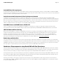
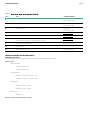
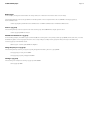
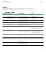
Quick reference implementation
of Oracle RAC and RHEL 6 using
HPE 3PAR Peer Persistence
Technical white paper
Technical white paper
Contents
Introduction ....................................................................................................................................................................................................................................................................................................................................................3
Terminology...................................................................................................................................................................................................................................................................................................................................................3
Features and benefits ...........................................................................................................................................................................................................................................................................................................................3
Requirements ..............................................................................................................................................................................................................................................................................................................................................4
Host persona generic ALUA ................................................................................................................................................................................................................................................................................................... 4
Verify each VV has same WWN on both arrays .................................................................................................................................................................................................................................................... 4
Verify VLUN status on both arrays ...................................................................................................................................................................................................................................................................................4
Quorum Witness ................................................................................................................................................................................................................................................................................................................................. 5
Management port on HPE 3PAR StoreServ ............................................................................................................................................................................................................................................................. 5
Unidirectional versus bidirectional Peer Persistence .............................................................................................................................................................................................................................................. 6
Oracle RAC Grid Infrastructure—ASM groups and RC groups ...................................................................................................................................................................................................................... 6
Planned switchover ................................................................................................................................................................................................................................................................................................................................ 7
Unplanned failover and recovery .............................................................................................................................................................................................................................................................................................. 8
Recovery—Example for primary array power failure........................................................................................................................................................................................................................................ 8
Sequence to recover and switchback ............................................................................................................................................................................................................................................................................. 8
Handling other failures ................................................................................................................................................................................................................................................................................................................. 8
Site A to QW and Array-to-array communication failure .............................................................................................................................................................................................................................. 9
Site B to QW and array-to-array communication failure ............................................................................................................................................................................................................................... 9
Site A and site B both lose communications to the QW ................................................................................................................................................................................................................................9
Site A and site B to QW and array-to-array communication failure .................................................................................................................................................................................................... 9
Oracle Automatic Storage Manager (ASM)—Group Usage ............................................................................................................................................................................................................................. 9
Oracle OCR/Vote disk requirements..............................................................................................................................................................................................................................................................................10
Oracle cluster network interconnect in Peer Persistence environment ........................................................................................................................................................................................10
Oracle RAC listeners and SCAN listener, SCAN IP, VIP.................................................................................................................................................................................................................................10
HPE 3PAR Quorum Witness Hosting ...........................................................................................................................................................................................................................................................................10
Remote Copy replication links .............................................................................................................................................................................................................................................................................................10
Quick start—Step sequence to setup Oracle RAC with Peer Persistence .........................................................................................................................................................................................10
Command examples for Peer Persistence ................................................................................................................................................................................................................................................................ 12
Appendix........................................................................................................................................................................................................................................................................................................................................................14
Add and remove volumes online from an Oracle ASM group in a Remote Copy group ...............................................................................................................................................14
Technical white paper
Page 3
Introduction
HPE 3PAR StoreServ Peer Persistence Software enables HPE 3PAR StoreServ systems located in different data centers at metropolitan distances
to act as peers to each other, presenting a continuous storage system access to hosts connected to them. Local hosts can access remote
StoreServ arrays and remote hosts can access local StoreServ arrays. This capability allows users to configure a high-availability solution between
two sites or data centers where storage access, failover, and failback remains completely transparent to the hosts and applications running on
those hosts.
Compared to traditional cluster failover models where upon failover, the applications must be restarted, Peer Persistence Software allows hosts to
remain online serving their business applications. They can be online even when they switch the storage access from the original site to the
storage array on the remote site, resulting in a much improved recovery time. Latencies due to distance and network bandwidth are still critical
factors to take into account.
This paper provides information about deploying Oracle RAC 11gR2 Grid Infrastructure across two data centers or sites using HPE 3PAR
StoreServ Peer Persistence on StoreServ Storage systems. This paper does not cover performance aspects and impacts. HPE services can be
engaged to assist with performance analysis of the customer’s environment.
Terminology
Throughout this paper, the volume that is part of a primary Remote Copy group is identified as the primary or source volume. The replicated
volume in the secondary Remote Copy group is called the remote or target volume. Volumes created on a HPE 3PAR StoreServ are called Virtual
Volumes, or VVs. A VV exported to the host is known as a VLUN. A zoning operation creates a logical connection in the Fiber Channel (FC) SAN
between an FC host bus adapter (HBA) on a server and one on a storage system.
Oracle RAC ASM diskgroup volumes (VVs) are configured into Peer Persistence Remote Copy groups. These VVs are allocated to vvsets that are
being used in the Remote Copy group and Oracle ASM diskgroup.
Features and benefits
Peer Persistence is a high availability configuration between two data centers in which the Oracle RAC hosts are setup in a cluster configuration.
It has access to storage arrays in both sites. Each Oracle RAC host will have an active set of paths and a standby set of paths. Storage volumes
created on one storage array are replicated to the other array using synchronous Remote Copy to ensure that the volumes are in sync at all times.
Peer Persistence Software takes advantage of the asymmetric logical unit access (ALUA) capability that allows paths to a SCSI device to be
marked as having different characteristics. With ALUA, the same LUN can be exported from both arrays simultaneously, but only the paths to the
side that accept writes to the volume will be marked as active. The paths to the secondary side volume will be marked as standby preventing the
host from performing any I/O using those paths. In the event of a non-disruptive transparent failover scenario, the standby paths are marked as
active and host traffic to the primary storage array is redirected to the secondary storage array without impact to the hosts.
The Peer Persistence Software supports bidirectional replication, which enables each site to perform as a disaster recovery center for the other.
It enables users to move their applications and volumes within an application from one site to another based on their business and performance
needs without impacting the applications running on those hosts. This paper looks at quick setup concepts for Oracle Real Application Clusters
as the application with client connections using Oracle Single Client Access Name (SCAN) listeners.
In the context of Oracle RAC clusters and Grid Infrastructure, ASM groups can be configured as active on either the primary or secondary
storage array. As in any other compute environment, performance must be taken into account as to where the Oracle ASM group will reside.
The Oracle RAC nodes can be in either physical location for active access.
Peer Persistence achieves automatic transparent failover in the event of a complete array or data center failure with the help of the Quorum
Witness (QW) software. The QW software needs to be installed at a third site. It will act as an independent witness should one of the arrays or
data centers become unavailable.
Technical white paper
Page 4
Requirements
• Firmware version on both HPE 3PAR StoreServ arrays must be 3.2.2 or newer.
• The sites must be set up in a Remote Copy 1-to-1 configuration with synchronous mode. This paper does not cover 1-to-many configurations.
• The round-trip latency between the two sites must be 2.6 milliseconds or less.
• QW software must be installed on a virtual machine using the QW OS image at a third site.
• The HPE 3PAR StoreServ arrays communicate with the QW via the management port over TCP/IP. The Quorum Witness needs to be
reachable from both sites via TCP/IP network.
• This non-disruptive failover configuration is supported with Oracle Real Application Clusters 11gR2
• All source and target volumes exported from the two HPE 3PAR StoreServ arrays must have the same volume WWN identifier.
• Hosts have to be connected to the StoreServ Storage system using FC, iSCSI, or FCoE.
• All associated hosts are connected to both arrays through multipath with ALUA support.
• The Oracle RAC hosts that these volumes are exported to must be configured on the array with host persona 2 (generic-ALUA), which
supports host capability of ALUA configuration.
For the latest supported configuration and requirement for HPE 3PAR Peer Persistence in an Oracle environment, refer to:
hpe.com/storage/spock/. The information in the SPOCK takes precedence over any information in the document.
Host persona generic ALUA
Host personas are a set of behaviors that permit hosts connected to FC or iSCSI ports on the system to deviate from the default host behavior.
By assigning a persona to a host, multiple host types that require distinct customized responses can share a single physical port on HPE 3PAR
StoreServ. For example, hosts running Windows®, Linux®, and AIX operating systems can all connect to the same HPE 3PAR StoreServ port.
This simplifies connecting hosts to the system and reduces management costs related to complex host connections.
Persona 2 supports ALUA path management and it must be used for host configurations that have Linux hosts connected to both the primary
and the secondary arrays. Existing Linux hosts defined with host persona 1 should be changed to persona 2 if these hosts are connected to both
primary and secondary array.
Verify each VV has same WWN on both arrays
It is important that the source and the target volumes on the HPE 3PAR StoreServ arrays have the same identity when both volumes are
exported to the same Oracle RAC host. Hence, both the primary and remote VVs should have the same WWN. The user can create volumes
with the same WWN automatically using the new option in “admitrcopyvv” command. See the HPE 3PAR StoreServ Remote Copy Software user’s
guide for instructions on how to use the admitrcopyvv command. The HPE 3PAR Management Console (MC) also gives the users option to
create VVs with the same WWN when configuring RC groups.
The replicated volume WWN can also be changed later, using the “setvv –wwn” command—this can be done if the volumes are created using the
management console or any method other than the admitrcopyvv. See the HPE 3PAR StoreServ Command Line Interface Administrator’s manual
or the HPE 3PAR StoreServ Management Console Online Help for further instructions on how to edit a VV’s WWN.
Verify VLUN status on both arrays
Make sure that volumes are exported to the host from both HPE 3PAR StoreServ arrays. Once the volumes are exported from both arrays, the
“showvlun” command will show the state as “active” for VLUNs exported from the source side and “standby” for the VLUNs exported from the
target side. Oracle RAC hosts will send I/O requests only to the LUNs reported as active. In RHEL 6 DM multipath paths that are active show up
with a status of ready and standby paths show up with a status of ghost.
On the primary array, Remote Copy creates a vvset that can be used if desired. A vvset created by Remote Copy takes the format of
RCP_groupname. If the group name is TEST, the vvset will be named RCP_TEST. On the remote array, Remote Copy does the same with the
vvset name having an extension. These vvsets can be used when exporting the VVs and creating the VLUNs.
Technical white paper
Page 5
Quorum Witness
The HPE 3PAR StoreServ QW software enables transparent automatic failover between the two sites in a cluster. The QW software is updated
regularly with status information from the HPE 3PAR StoreServ arrays. If one of the HPE 3PAR StoreServ arrays fails, the surviving HPE 3PAR
StoreServ array detects that the QW is not being updated by the failed array. It initiates a failover operation on any secondary groups associated
with that failed array.
Note
QW details have to be setup at the target level. The transparent failover will occur only for Remote Copy groups that use the target if they have
already started and have the “auto failover” policy set with the “setrcopygroup” command. Failover is not automatic for Remote Copy groups
between two similar HPE 3PAR StoreServ systems, which do not have the “auto failover” policy set. For HPE 3PAR OS 3.1.3 or later, you have to
set the path management as well. A volume group must have the path management policy set if it is to be valid for automated and transparent
failover. If this policy is not set, then no automatic failover will occur if a disaster strikes.
The QW is set up on a third site where events that may impact site A or site B cannot impact the QW site at the same time. In other Oracle
stretch cluster configurations, the Oracle OCR/Vote diskgroup must also be on a third site. With the implementation of Peer Persistence, this is
not the case, since the OCR/Vote volumes are replicated real time in a synchronous manner. The QW connects to arrays on both sites using
non-RC links. With the above two configuration characteristics (site and link independence), QW helps determine the following nature of failures:
• RC link failure: The QW can detect if the two arrays are alive but are not communicating because of an RC link failure. The QW would still be
receiving updates from both the arrays.
• Array or site failure: The QW can detect when one of the arrays or sites fail. The QW would not be receiving updates from one of the array that
has failed.
The QW software is packaged as a VMware® OVF or Windows 2012 Hyper-V package for deployment in an environment. It needs to be imported
on an ESXi or Hyper-V host. Refer to the Remote Copy appendix for Quorum Witness for support details. With the release of HPE 3PAR OS 3.2.1,
a Microsoft® Hyper-V QW package is available for users who choose to deploy it on that platform. The QW virtual machine should not be stored
on a data store allocated from either of the arrays that are part of the Peer Persistence configuration. If the data store is located on one of the
arrays that is part of the Peer Persistence configuration, an array failure could make the data store unavailable. In turn, access to the QW virtual
machine will be lost. The QW software uses port 8080 to communicate with the two HPE 3PAR StoreServ systems in the quorum. So, firewall
rules need to be changed to open port 8080 at the QW site.
The QW is a passive component of the configuration and the software itself does not provide any high availability, however, the virtual machine
can be made highly available by using VMware HA or Fault Tolerance or Microsoft Failover Clustering for the Hyper-V–based QW package. For
the latest supported configuration and requirement for HPE 3PAR Peer Persistence QW, refer to: hpe.com/storage/spock/.
Management port on HPE 3PAR StoreServ
The HPE 3PAR StoreServ communication with the QW uses the HPE 3PAR StoreServ management interface or the CLI. The network should be
setup such that the QW server has network connectivity to the admin interface on both arrays. It is required to connect the administration port
from a minimum of two controller nodes to the network. However, if the array has more than two controllers the best practice is to connect all
controller nodes to the network.
Technical white paper
Page 6
Unidirectional versus bidirectional Peer Persistence
Oracle RAC Grid Infrastructure can be set up for unidirectional or bidirectional configurations. In a unidirectional configuration, all Oracle ASM
diskgroups must be configured at the primary site and in the event of an array or site failure, all of the Oracle ASM diskgroups will be failed over
to the remote site.
For bidirectional setup, Oracle ASM groups can be balanced across primary and remote sites.
In this configuration, Oracle ASM redundancy is set to external, and all data redundancy is handled through the HPE 3PAR RAID configurations
of RAID 5 for data and archive and RAID 1 for redo logs. Oracle failure groups are not used.
Oracle RAC Grid Infrastructure—ASM groups and RC groups
In this configuration, each host can access LUNs exported from both the sites. Figure 1 shows a sample configuration. This setup helps in
protecting against a storage failure at a site. If the HPE 3PAR StoreServ array in site A fails, a failover will occur at the HPE 3PAR StoreServ array
on site B. This action is transparent and automatic allowing Oracle RAC nodes on site A continued access to storage on site B without any
interruption. Of course, this implies that customers need to have sufficient bandwidth between their sites since traffic from the host will be routed
across the inter-site link connections to the secondary array at the remote site.
Figure 1. Oracle 11gR2 RAC Grid Infrastructure—Sample of ASM diskgroups in a Peer Persistence configuration. This is an example
and could also involve more ASM groups such as user tablespaces or archive log groups.
Technical white paper
Page 7
Planned switchover
A switchover operation migrates the Remote Copy group role from source to target without impacting host I/O. For, this operation, the associated
hosts should be connected to the arrays on both sites. This is a planned operation and the Remote Copy groups should start and synchronize for
this command to work.
This operation is useful when users are looking for workload mobility between the two sites. One can use the switchover command to reverse the
replication resulting in site B hosts being able to access the LUNs locally from site B array. The system performs the following action as part of a
switchover operation:
• I/O from the hosts to the volumes in the source Remote Copy group is blocked and in flight I/Os are allowed to drain. The Remote Copy group
is stopped and snapshots are taken on the primary array.
• The primary array target port group is changed to transition state and it sends a remote failover request to the secondary Remote Copy
group.
• The secondary array target port group is then changed to transition state and it takes a recovery point snapshot.
• The secondary Remote Copy group changes state to become primary-reversed (primary-rev) and makes the volumes read or write.
• The primary-rev target port group is changed to active state and the array returns a failover complete message to the primary Remote Copy
group.
• The primary array target port group is changed to standby state and any blocked I/O is returned to the host with a sense error: “NOT READY,
LOGICAL UNIT NOT ACCESSIBLE, TARGET PORT IN STANDBY STATE.”
• The host will then perform SCSI inquiry requests to detect what target port groups have changed and which paths are now active and I/O will
now be serviced on the active path to the primary-reverse Remote Copy group.
• All operations to this point should complete within 30 seconds to ensure that host I/O does not timeout.
• The primary Remote Copy group will then send a remote recover request to the primary-reverse Remote Copy group. The primary-reverse
Remote Copy group will perform a recover operation and will change the primary Remote Copy group state to secondary-reverse state.
The Remote Copy group will then be started from primary reverse to secondary reverse.
• When the primary-reverse and secondary-reverse volumes are back in sync, the snapshots that were taken on both sides will be removed.
The Remote Copy group will then undergo a reverse (-natural) operation. This operation will change the primary-reserve group to primary and
secondary-reverse group to secondary. It is possible for this operation to time out or fail, if the target links go down during processing. If this
happens, issue the setrcopygroup reverse—natural command to complete the process manually. The system is now fully reversed and ready
for another switchover request.
Note
On a busy array, it might take a long time to take group snapshots if there are many volumes in the group. Since it is important for the switchover
operation to start serving I/O from the primary-reverse side within 30 seconds, the best practice is for Remote Copy groups in a Peer Persistence
setup to contain no more than 30 volumes.
Technical white paper
Page 8
Unplanned failover and recovery
In an unplanned failover scenario, Peer Persistence is ready to handle things immediately. For example, in a bidirectional Remote Copy setup, if
the power fails on the primary storage array, all the VVs that are exported to the primary array as active are switched over to the secondary array
as active. So looking at the VLUN status (showvlun) on the secondary array, it will show all volume paths as active. Multipathing path failure and
path status switching will occur to reflect that all the volumes are active. This is where ALUA support is needed. In RHEL 6, the output of the
multipath –ll command will show all active paths with a ready status and all standby paths as a ghost status.
From an Oracle RAC perspective, there may be a 15–20 second delay in real-time transactions while the paths are switching. The amount of delay
is dependent on the characterization of the workload and the number of VVs involved in the failover. As stated earlier, it is best to keep the
number of VVs in a copy group below 30 per group. The client connectivity will only be impacted if the RAC node(s) go down with the array. In
this case, failover of the client connections will happen through the SCAN listener or whichever listener configuration exists. The design of the
client connections is no different from a non-stretched standard RAC implementation.
Recovery—Example for primary array power failure
In the earlier example, once the primary site array is powered on, the environment must be recovered back from its normal state. The status of
the arrays and Remote Copy are as follows:
• Primary site array—The copy operation is in a stopped status and the VVs re now in a “failsafe” mode.
• Secondary site array—The copy operation is in a stopped status and any of the VVs that were originally in a secondary state are now in a
“Primary-Rev” state. The “Primary” state groups are in a stopped status and still in a “Primary” state. All groups are exported actively to all the
RAC nodes.
Sequence to recover and switchback
Following is the sequence of steps that must occur to recover and switch back to a normal state:
• Identify all the groups in “Primary-Rev” status (showrcopy | grep Primary-Rev) from the secondary array (array that did not fail)
• Recover these groups to synchronize the volumes (setrcopygroup recover <GROUP>)
• Monitor the recovery synchronization progress until volume in group is resynchronized (showrcopy)
• Change the status of the group from “Primary-Rev” to “Primary” (setrcopygroup reverse –natural <GROUP>)
• Switch all the group back to the original configuration (setrcopygroup switchover <GROUP>)
• Start the remaining group copy operations and monitor the synchronization progress due to write that occurred on the VVs while the failover
is in place
Once these steps have been completed, the environment is fully recovered. If the secondary site were to fail, the same procedure would be used,
except the recovery steps would occur from the primary array.
Handling other failures
Peer Persistence with QW can identify different types of failures and perform transparent failover automatically. Peer Persistence will perform
transparent failover only for Remote Copy groups that have the auto failover and path management enabled.
Array-to-array communication failure
In the case of an array-to-array communication failure, the HPE 3PAR StoreServ continues to send and receive communication to and from the
QW. Automatic transparent failover does not occur and host I/Os continue to go to their primary volumes; however, replication of I/O across RC
links will stop due to the failure.
Single site to QW communication failure
In the case where the arrays at either site A or site B lose connectivity with the QW, an automatic failover will not occur. Host I/O will continue and
replication of I/O across RC links will continue normally. An automatic failover does not need to occur because the two HPE 3PAR StoreServ
arrays can still communicate with one another via the replication links they share.
Technical white paper
Page 9
Site A to QW and Array-to-array communication failure
If the array in site A is isolated due to a dual network failure (communication with the QW fails and the replication links to the array in site B fails);
Remote Copy groups that are in primary state on the array in site A will be transitioned to failsafe mode. They will stop serving I/O to the ESXi
and Hyper-V hosts in site A. The array in site B (which is still communicating with the QW) will perform an automatic failover and host I/O will be
redirected to the new primary volumes in site B.
Site B to QW and array-to-array communication failure
This is the same as the previous case with the difference that site B becomes isolated due to a dual network failure.
Site A and site B both lose communications to the QW
In the case of a communication failure with the QW from both sites, but where the Remote Copy links remain operational, both arrays will be
aware of each other’s operational state. Automatic failover does not happen and host I/Os continue in the primary volumes; replication of I/O
across RC links will continue as normal.
Site A and site B to QW and array-to-array communication failure
In the case where all network communication between the arrays and the QW, and the communication between both arrays fail, both arrays will
be isolated. This happens because they cannot communicate with each other over the RC links nor can they communicate with the QW. In this
case, Remote Copy groups that are primary will go into failsafe mode and stop serving I/O, and failover actions will not be performed. This will
result in host I/O failure and replication of I/O across RC links will stop due to the failure. See table 1 for a list of failure type comparisons.
Table 1. Peer Persistence failure types
REPLICATION STOPPED
AUTOMATIC FAILOVER
HOST I/O IMPACTED
Array-to-array Remote Copy links failure
Yes
No
Yes
Single site to QW network failure
No
No
No
Single site to QW network and array–to-array Remote Copy link failure
Yes
Yes
No
Both sites to QW network failure
No
No
No
Both sites to QW network and array-to-array Remote Copy link failure
Yes
No
Yes
Oracle Automatic Storage Manager (ASM)—Group Usage
Oracle ASM groups can be created per the requirement of the user’s environment. In general, it is best to keep the OCR/Vote either on its own or
with the system tablespaces. A separate ASM group named GRID or SYSTEM can be used. There should be a redo log group for each node using
RAID 1 and a separate ARCHIVELOG group using RAID 5 or RAID 1. Following is an example of how some groups might be deployed but it’s only
an example.
Table 2. Sample ASM and RC group layout
SITE A
SITE B
GRID—active paths
GRID—standby paths
SITE_A_REDO—active paths
SITE_A_REDO—standby paths
SITE_B_REDO—standby paths
SITE_B_REDO—active paths
ARCHIVELOG—standby paths
ARCHIVELOG—active paths
DATA_TABLESPACES1—active paths
DATA_TABLESPACES1—standby paths
DATA_TABLESPACES2—standby paths
DATA_TABLESPACES2—active paths
The design of the user tablespace groups can be sized for the need of the environment. Oracle recommends at least four volumes per group and
each volume should be of the same allocated size and same speed. A mixture of fully provisioned and thin provisioned volumes is acceptable.
Technical white paper
Page 10
Oracle OCR/Vote disk requirements
A separate Remote Copy group should be created with at least four small VVs and separately named, for instance, GRID or SYSTEM. The OCR
and Vote will not be required to be put on a third site because Remote Copy will replicate it. Other vote files can be created on other ASM volume
groups as needed or required by the Oracle cluster architect.
Oracle cluster network interconnect in Peer Persistence environment
The Oracle interconnect requirements are no different for Oracle RAC in a Peer Persistence configuration than any other Oracle RAC
environment. As has always been the case, latency is the critical factor for the cache fusion interconnect. Careful consideration and following the
Oracle documentation for RAC interconnects is recommended. It will be of value to have information on the latency of the network between the
two sites or data centers. The design considerations will be similar to those used on other Oracle stretch cluster solutions. Interconnect can be
TCP/IP or InfiniBand. Latency is still a key factor as in any Oracle RAC environment.
Oracle RAC listeners and SCAN listener, SCAN IP, VIP
There is no change in how the listeners, SCAN listener, SCAN IPs, or virtual IPs are configured or deployed in a RAC environment using
Peer Persistence. Follow the same guidelines and procedures used in implementing a standard Oracle RAC Grid Infrastructure environment.
HPE 3PAR Quorum Witness Hosting
Given how critical the QW is to operation of HPE 3PAR Peer Persistence, it is highly recommended that the QW virtual machine be hosted
outside the stretched cluster environment. It should not be on the HPE 3PAR arrays used in the HPE 3PAR Peer Persistence deployment it
arbitrates or the vSphere hosts that are part of the Metro Cluster. It is possible to use a single QW to support up to four HPE 3PAR Peer
Persistence deployments. This will give user the option for consolidation to save on resources and for ease of management as well. For the
latest supported configuration and requirement for HPE 3PAR Peer Persistence QW, refer to: hpe.com/storage/spock/.
Remote Copy replication links
The current release of the HPE 3PAR Peer Persistence with 3.2.2 supports FC, FCoE, and iSCSI host connectivity. However, it is recommended
that RCFC be used for the synchronous replication of data between the arrays in a Peer Persistence configuration. Use of RCFC will ensure a high
bandwidth and low latency connection for the replication of data between the arrays as it uses a patented protocol for synchronous replication
that only requires a single round trip across the replication links to replicate an I/O smaller than 80K in size.
Quick start—Step sequence to setup Oracle RAC with Peer Persistence
This section describes the step sequence for setting up Peer Persistence specifically with Oracle RAC 11gR2 Grid Infrastructure. Refer to Oracle
documentation for specifics on the Oracle setup steps and the HPE 3PAR Remote Copy user guide for specifics on setting up Peer Persistence.
This section will use an example for clarity but actual storage requirement for Oracle RAC would be different for each customer.
In this quick-start scenario, the customer wants a Peer Persistence configuration using two StoreServ arrays and four Oracle RAC server nodes.
Site A will have two Oracle RAC nodes with HPE 3PAR storage and site B will have two RAC nodes with HPE 3PAR storage. All RAC nodes are
zoned to communicate and allocate storage to both site A and site B arrays.
Following is an example of the sequence of steps. There are four types of steps. HPE 3PAR is normal storage setup, PP is Peer Persistence
specific, OS relates to RHEL 6, and ORA is Oracle related. There are also unspecified OS steps within the ORA steps. It is assumed the reader is
an experienced Oracle RAC user.
Technical white paper
Page 11
Refer to the quick setup guide in the reference section of the Remote Copy user manual for more Peer Persistence detail.
Table 3. Array setup steps to be completed
FOCUS
STEP
COMMAND REFERENCE
HPE 3PAR
Set up Remote Copy links per RC guide
controlport,
Remote Copy user guide
PP
Create copy targets
setrcopytarget
Remote Copy user guide
HPE 3PAR
Verify configuration and test Remote Copy Links
showport, controlport,
Remote Copy user guide
ORA
Determine storage requirements, space, number of volumes, and ASM groups. Example ASM group
for GRID, SYSTEM, LOG, ARCHIVELOG, USER, etc.
http://docs.oracle.com
ORA
Determine which ASM groups will be primary to site A; and which ASM groups will be primary to site B
Site A example—Primary groups GRID (OCR/VOTE), SYSTEM, SITEAREDO, USER1
Site B example—Primary groups SITEBREDO, ARCHIVE, USER2
http://docs.oracle.com
PP
Set up QW server on third site—create VMware or Hyper-V VM and install QW OS image. Use QW
setup procedure in Remote Copy user guide.
setrcopytarget witness, showrcopy -qw
Remote Copy user guide
HPE 3PAR
On the site A array, create primary VVs for ASM groups using appropriate RAID and sizes. VVs must
be of type cpvv or tpvv.
createvv, setvv
Remote Copy user guide
HPE 3PAR Implementation Guide
for Linux
HPE 3PAR
On the site B array, create primary VVs for ASM groups using appropriate RAID and sizes.
HPE 3PAR
On the site A array, create secondary VVs for ASM groups with an rc.r extension
This step can also be done as an
option in the admitrcopyvv command
later.
HPE 3PAR
On the site B array, create secondary VVs for ASM groups with an rc.r extension
This step can also be done as an option
in the admitrcopyvv command later.
PP
Change the WWN on the secondary VV to the same WWN as the primary VV
showvv –d, setvv –wwn
Remote Copy user guide
This step can also be done as an
option in the admitrcopyvv command
later.
PP
Create copy groups using synchronous mode
creatercopygroup
Remote Copy user guide
PP
Admit the Remote Copy VVs into their respective copy groups
admitrcopyvv
Remote Copy user guide
PP
Create VLUNs for all RCP vvsets created by admitrcopyvv
showvvset, createhostset, createVLUN
Remote Copy user guide
OS
Rescan disks on all RAC nodes and verify connectivity
rescan-scsi-bus.sh, multipath -ll
Technical white paper
Page 12
Table 3. Array setup steps to be completed (cont’d)
FOCUS
STEP
COMMAND REFERENCE
PP
Set path_management and auto_failover policies
setrcopygroup pol
Remote Copy user guide
PP
Start the copy groups and monitor until fully synchronized
startrcopygroup, showrcopy
Remote Copy user guide
PP
Stop the copy process
stoprcopygroup
Remote Copy user guide
ORA
Install Oracle Grid Infrastructure
http://docs.oracle.com
ORA
Install RAC Database
http://docs.oracle.com
ORA
Create ASM groups on RC group disks, move logs, setup archive logging in appropriate ASM group,
create user tablespaces, and place in proper ASM group or RC group
http://docs.oracle.com
PP
Start RC groups for synchronization
startrcopygroup, showrcopy
ORA
Verify Oracle RAC
PP
Test environment by failing over
Command examples for Peer Persistence
Creating transport layer
Here’s an example for creating transport layers. In this example, the transport type used is FC.
On site A array:
Take ports offline
controlport offline 0:2:1
controlport offline 0:2:2
Set up interfaces
controlport config rcfc –ct point –f 0:2:1
controlport config rcfc –ct point –f 0:2:2
Initialize ports
controlport rcfc init –f 0:2:1
controlport rcfc init –f 0:2:2
Check ports:
showport -rcfc
On site B array: (Perform the same procedure)
Setrcopygroup switchover
Technical white paper
Page 13
Define targets
In this example, the targets are defined for two arrays names site 1 and site 2. This must be done on both arrays.
The following example creates a target definition named System2 on the local system where the node WWN of the target system is
20010002AC000060:
creatercopytarget System2 FC 20010002AC000060 0:4:1:22410002AC000060 1:4:1:23410002AC000060
Create a copy group
The following example creates a synchronous mode volume group named GRID whose target system is site 1:
creatercopygroup GRID site-A:sync
Add VVs from both sites to copy group
In the following example, the admitrcopyvv command adds the volume grid.0 to the primary volume group (GRID). At the same time, it creates
and adds the grid0.r on the target system site B to the corresponding secondary volume group that was previously created when the
creatercopygroup command was issued:
admitrcopyvv -createvv grid.0 GRID Site-B:grid.0.r
Change the policy on a copy group
The following example sets the group policies path_management and auto_failover for group GRID:
setrcopygroup pol auto_failover GRID
setrcopygroup pol path_management GRID
Starting a copy group
The following is an example for starting copy group named GRID.
startrcopygroup GRID
Technical white paper
Page 14
Appendix
Add and remove volumes online from an Oracle ASM group in a Remote Copy group
Adding a single VV to a Remote Copy group and ASM group
Table 4. Setup steps to be completed
STEP NUMBER
STEP DESCRIPTION
COMMAND EXAMPLE
NOTES
1
Create new TPVV on primary array
createvv -tpvv FC_r5 Serv1_LOG.4 12g
Create an extra volume for redo logs
2
Create copy VV on secondary array
createvv -tpvv FC_r5 Serv1_LOG.rc.r.4 12g
Remote Copy replicate
3
Set the WWN on the remote VV to the WWN
used by the primary VV
setvv -wwn
60002AC000000000000005AB00000072
Serv1_LOG.rc.r.4
Make the secondary replicate VV WWN to
match the primary VV
4
Add snapshot space to both VVs
setvv -snp_cpg FC_r5 Serv1_LOG.4
setvv -snp_cpg FC_r5 Serv1_LOG.rc.r.4
Volume must have snapshot cpg and be of
type cpvv
5
Stop the REDO COPY GROUP
stoprcopygroup SERVER1_REDOLOGS
Synchronization needs to be paused
6
Admit VVs to the group
admitrcopyvv Serv1_LOG.4 SERVER1_REDOLOGS
s115:Serv1_LOG.rc.r.4
7
Show vvset for redo group
showvvset | grep RCP | grep REDOLOGS
Attention: If the contiguous LUN numbering
is filled, a higher LUN number must be chosen;
if multiple dashed lines are seen in the output
of the showvvset command; this is normal
8
Create VLUNs on VVs in both arrays exporting
to all RAC nodes
createVLUN Serv1_LOG.4 200 set:c3-dl380g9-02
createVLUN Serv1_LOG.4 200 set:c3-dl380g9-03
The volume may have already been exported
on the remote side; use the showvlun
command to check; this depends on whether
the remote VV was created manually or
automatically created with the admitrcopyvv
command
9
Start copy group
startrcopygroup SERVER1_REDOLOGS
showrcopy
Allow copy group to resync completely
10
Rescan disks on RAC nodes
rescan.scsi-bus.sh
This must be done on each node
11
Label the disk as ASM disk
If using ASMLib:
oracleasm scandisk
oracleasm createdisk REDLOGDISK4
/dev/mapper/mpathx
12
Add disk to ASM group
ALTER DISKGROUP DATA ADD DISK
‘/dev/mapper/mpathx’ REDOLOGDISK4
REBALANCE POWER 11;
Technical white paper
Page 15
Removing a single VV to a Remote Copy group and ASM group
Table 5. Setup steps to be completed
STEP NUMBER
STEP DESCRIPTION
COMMAND EXAMPLE
NOTES
1
Find the VV to remove from the ASM group
SQL>select group_number, name, TOTAL_MB,
FREE_MB from V$asm_disk_s
Logged onto SQL PLUS with the Oracle Home
set to Grid Home and Oracle DIS set to +ASM1;
connection string
sqlplus/as sysasm
2
Remove the identified disk from the ASM group
SQL> alter diskgroup SERVER1_LOGS drop disk
SERVER1_LOGS_0004;
Rebalance can have some effect on real-time
Oracle transactions; see docs.oracle.com/en/
for the ASM administrators guide for setting
appropriate rebalance powers
3
On the standby array, unexport the paths for
the vvset; do this for each RAC node
removeVLUN set:RCP_SERVER1_REDOLOGS.r114
57 set:c3-dl380g9-02
removeVLUN set:RCP_SERVER1_REDOLOGS.r114
57 set:c3-dl380g9-03
The step is to prevent the VV from going
active on the remote site
4
Stop the copy group
stoprcopygroup SERVER1_REDOLOGS
5
Unexport VLUNs on the primary array for the
VV
removeVLUN set:RCP_SERVER1_REDOLOGS.r114
57 set:c3-dl380g9-03
6
Dismiss the VV from the Remote Copy group
dismissrcopyvv Serv1_LOG.4
SERVER1_REDOLOGS
7
Export back the VLUNs for the remote array
vvset; do this for each RAC node
createVLUN set:RCP_SERVER1_REDOLOGS.r114
57 set:c3-dl380g9-02
createVLUN set:RCP_SERVER1_REDOLOGS.r114
57 set:c3-dl380g9-03
8
Scan devices on all RAC nodes
rescan-scsi-bus.sh
9
Restart Remote Copy group
startrcopygroup SERVER1_REDOLOGS
Done
Technical white paper
Learn more at
hpe.com/go/3PAR
Sign up for updates
Rate this document
© Copyright 2015 Hewlett Packard Enterprise Development LP. The information contained herein is subject to change without notice.
The only warranties for Hewlett Packard Enterprise products and services are set forth in the express warranty statements accompanying
such products and services. Nothing herein should be construed as constituting an additional warranty. Hewlett Packard Enterprise shall
not be liable for technical or editorial errors or omissions contained herein.
Microsoft and Windows are either registered trademarks or trademarks of Microsoft Corporation in the United States and/or other
countries. Oracle is a registered trademark of Oracle and/or its affiliates. Linux is the registered trademark of Linus Torvalds in the U.S.
and other countries. VMware is a registered trademark or trademark of VMware, Inc. in the United States and/or other jurisdictions.
4AA6-2643ENW, November 2015