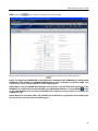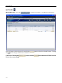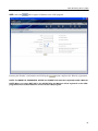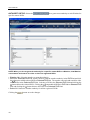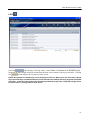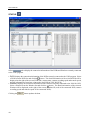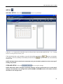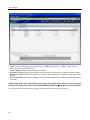
1
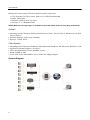
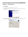
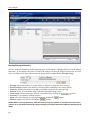
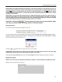
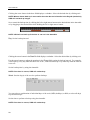
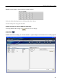
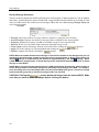
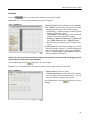
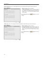
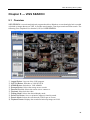
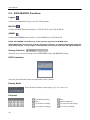
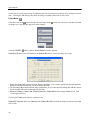
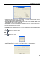
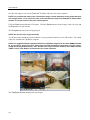
Video Streaming Server (ViSS)
Table of Contents
Chapter 1 — Overview ................................................................................. 1
1.1
Overview ........................................................................................ 1
1.2
Product Information ........................................................................ 1
Chapter 2 — ViSS Software ......................................................................... 3
2.1
Installation ...................................................................................... 3
2.2
Configuration .................................................................................. 7
2.3
Operation ........................................................................................ 8
Chapter 3 — ViSS ADMIN ......................................................................... 11
3.1
Overview ...................................................................................... 11
3.2
ViSS ADMIN Functions ................................................................ 11
Chapter 4 — ViSS WATCH ........................................................................ 35
4.1
Overview ...................................................................................... 35
4.2
ViSS WATCH Functions ............................................................... 36
Chapter 5 — ViSS SEARCH ...................................................................... 39
5.1
Overview ...................................................................................... 39
5.2
ViSS SEARCH Functions ............................................................. 40
i
User’s Manual
ii
Video Streaming Server (ViSS)
Chapter 1 — Overview
1.1 Overview
ViSS is a Video Streaming Server. Many DVRs can be connected to the ViSS program at once, and many
watchers can simultaneously view images from DVRs registered on the ViSS program. ViSS is an intelligent
and advanced server technology to manage DVRs and watchers.
The ViSS software consists of the following programs.
ViSS server program – Runs the ViSS server system.
y ViSS Control.exe (Daemon program): Starts and stops the ViSS software.
y ViSS.exe: Supports real-time monitoring, searching, recording and backup.
y ViSS Backup.exe: Supports frame recovery backup and searching backup images.
ViSS client program
y ViSS ADMIN: DVR registration and program setup
y ViSS SEARCH: Search and playback of the DVR images saved in ViSS
y ViSS WATCH: Real-time monitoring for remote DVR images
1.2 Product Information
Product Components
y User’s Manual (This Document)
y ViSS Software Installation CD
y WIBU-KEY (USB)
System Requirements
Server System
Hardware
Maximum 16 users and 64 DVR (4 channel models) connections
y
y
y
y
CPU: Pentium4 2.4 GHz or faster, Dual core 2.8 GHz Recommended
RAM: 1GB or more
Hardware: 10GB or more free space
Network: T1, T3 Broadband Line
Maximum 64 users and 256 DVR (4 channel models) connections
y
y
y
y
CPU: Pentium4 2.8 GHz or faster, Dual core 3.0 GHz Recommended
RAM: 2GB or more
Hardware: 10GB or more free space
Network: T1, T3 Broadband Line
1
User’s Manual
Maximum 512 users and 512 DVR (4 channel models) connections
y
y
y
y
CPU: Pentium4 3.0 GHz or faster, Dual core 3.0 GHz Recommended
RAM: 3GB or more
Hardware: 10GB or more free space
Network: T1, T3 Broadband Line
NOTE: Make sure enough space is available on your hard disk drives for recording and backup.
Software
y Operating System: Windows XP Professional (Service Pack 1, Service Pack 2), Windows Server 2003
(Service Pack 1)
y Software Platform: JAVA (Auto installed)
y Protocol: TCP/IP, HTTP
Client System
y
y
y
y
y
Operating System: Microsoft® Windows® 2000, Microsoft® Windows® XP, Microsoft® Windows® Vista
Application: Internet Explorer 6.0 or above
CPU: Intel Pentium II (Celeron) 800MHz or faster
RAM: 512MB or more
VGA: AGP, Video RAM 8MB or more (1024x768, 24bpp or higher)
System Diagram
2
Video Streaming Server (ViSS)
Chapter 2 — ViSS Software
2.1 Installation
1. Insert the ViSS software installation CD into the sever computer.
2. Run the ViSSPremiumSetup.exe file. Click Next, and then install the software following the instructions
in the setup boxes.
3. When the following setup box appears, select the desired task and click Next. Install the software following
the instructions in the setup boxes.
3
User’s Manual
4. The progress bar shows the installation progress.
5. When installation is complete, the following setup box appears. Select all packages and click Finish.
NOTE: The selected programs will be installed on the computer in order.
6. When the following WIBU-KEY Setup box appears, click Next. Follow the instructions in the setup
boxes to install the WIBU-KEY (Lock) program.
4
Video Streaming Server (ViSS)
7. When the following JAVA setup box appears, select I accept the terms in the license agreement
and click Next. Follow the instructions in the setup boxes to install the JAVA program.
8. When the following box appears, click No to install other packages.
9. When the following TOMCAT setup dialog box appears, click the Next button. Select the TOMCAT
optional components as shown below and click Next. Follow the instructions in the setup boxes to install
TOMCAT.
NOTE: You do not need to install the TOMCAT program if the TOMCAT 5.5 program has already been
installed on the server.
5
User’s Manual
10. When the following command prompt box appears after TOMCAT is installed, configure the ViSS backup
mode following the instruction.
viss backup mode <0: normal, 1: frame recovery>: Enter 0 to back up recorded video in DVRs according
to the user-defined backup schedule. Enter 1 to back up recorded video in DVRs automatically when ViSS
fails to record because of an unexpected ViSS reboot or DVR disconnection.
NOTE: Refer to 3.2 Function of ViSS ADMIN Æ BACKUP for details.
Number of banks per storage min10, max200, default10: Enter the number of banks to allocate to a
storage folder (maximum 200, minimum 10). One bank equals 64MB.
NOTE: ViSS saves data in storages consisting of banks.
11. When the following setup box appears, install ViSS JSP PAGE following the instructions. When ViSS
JSP PAGE is installed, click Finish.
12. When the following setup box appears, enter the proper language encoding value for the client system
and click the Apply button. The default value is utf-8 (UNICODE).
13. Restart the computer to complete the installation.
6
Video Streaming Server (ViSS)
NOTE: You can check if the ViSS JSP PAGE has been installed properly. For example, if the ViSS
IP address is 1.2.3.4:
y When connecting from the server, connect to http://127.0.0.1:8080/ViSS and check if you can
connect to the ViSS Application.
y When connecting from the client computer, connect to http://1.2.3.4:8080/ViSS and check if
you can connect to the ViSS Application.
2.2 Configuration
Watchdog
ViSS Watchdog on the server checks the system status based on the preset watchdog interval and reboots
the system when an abnormal system operation is detected.
Select the ViSSControl.config file in the ViSS folder if you want to change the ViSS Watchdog settings.
The default settings are as follows:
AUTO_REBOOTING_ENABLED 1
Disables watchdog)
VISS_REBOOTING_WAIT_SECONDS 600
(1: Enables watchdog, 0:
(Watchdog system check interval)
NOTE: Before changing the ViSS Watchdog settings, first STOP the ViSS Daemon program (ViSS
Control).
NOTE: You must restart the system to apply changes after changing ViSS Watchdog settings.
Port
When the server uses a firewall with Microsoft Windows XP Service Pack 2 operating system or on network,
you should configure the ports as follows for network connections between the web browser and the server.
Watch:
Backup:
ViSS Control:
Recording Search:
Backup Search:
Storage Setup:
Applet:
Tomcat:
8016
8014
8010
10020
10021
8012
8050
8080
Virtual Memory
If you connect to more than 256 DVRs, increase the capacity of virtual memory to 3GB by adding the /3gb
option in the boot.ini file in the boot drive. Refer to the following example.
[boot loader]
timeout=30
default=multi(0)disk(0)rdisk(0)partition(2)\WINDOWS
[operating systems]
multi(0)disk(0)rdisk(0)partition(2)\WINDOWS="Microsoft Windows XP Professional"
/fastdetect /3gb
7
User’s Manual
2.3 Operation
ViSS Server Program
NOTE: The WIBU-KEY must be connected to the ViSS server in order to run the ViSS program.
When you restart the server system after installing the ViSS software, the ViSS daemon (ViSS Control) and
TOMCAT web server programs initiate automatically. You can also start the ViSS program by clicking
ViSS Service Run in the ViSS folder of the Startup menu or by double clicking the ViSS shortcut
icon
on the desktop. Then, connect a WIBU-KEY to a USB port.
ViSS Client Program
You can run the ViSS client program by connecting to the server system currently running on the web browser.
Connect to http://1.2.3.4:8080/ViSS (In this example, the ViSS IP address is 1.2.3.4. Obtain IP address
information from the system manager.).
Login
The ViSS Application program provides two ways of connection depending on the Watcher’s class: ViSS
ADMIN and ViSS PUBLIC. Connect to the ViSS program, and the ViSS Login page appears.
NOTE: ViSS ADMIN is available only to the watchers registered as ADMIN class. Refer to 3.2 ViSS
ADMIN Functions – WATCHER for details on the Watcher registration.
Enter the ID and password and click SIGN IN.
NOTE: The default ID is admin, and the default password is 12345678.
NOTE: When using Internet Explorer 7.0, a ViSS page might not be displayed in certain resolution.
In this case, set up Auto-hide the taskbar and Allow websites to open windows without address or
status bars functions according to the following procedures:
y Go to Control Panel Æ Taskbar and Start Menu Æ Taskbar and select an Auto-hide the taskbar
option.
y Go to Control Panel Æ Internet Options Æ Security Æ Custom Level… Æ Miscellaneous and select
an Allow websites to open windows without address or status bars option.
NOTE: When running the ViSS client program in the Microsoft Windows Vista operating system, it
is recommended to start Internet Explorer with elevated administrator permissions. Click the right
mouse button on the Internet Explorer icon and select the Run as administrator option from the context
menu. Otherwise, some functions of the ViSS client program might be limited.
8
Video Streaming Server (ViSS)
NOTE: There might be a problem with screen display or screen update due to low image transmission
speed when using the Microsoft Windows Vista operating system. In this situation, it is recommended
that you disable the Auto Tuning capability of your computer.
Run the Command Prompt with elevated administrator permissions (Go to the Start Menu Æ
Accessories Æ Command Prompt Æ Click the right mouse button and select the Run as administrator
option). Then, enter “netsh int tcp set global autotuninglevel=disable” and hit the enter key. Restart
your computer to apply the changes.
If you want to enable the Auto Tuning capability again, enter “netsh int tcp set global autotuninglevel=
normal” after running the Command Prompt with elevated administrator permissions. Restart your
computer to apply the changes.
9
User’s Manual
10
Video Streaming Server (ViSS)
Chapter 3 — ViSS ADMIN
3.1 Overview
ViSS ADMIN, the main administration program, controls the ViSS program. It allows watchers classified
as ADMIN to manage DVRs and watchers registered on the ViSS program, and to back up and record images.
The following is the Graphical User Interface (GUI) of ViSS ADMIN.
①
②
③
④
⑤
⑥
⑦
⑧
⑨
⑩
⑪
⑫
Start: Releases sleep mode on the ViSS server program.
Stop: Sets up sleep mode on the ViSS server program.
DVR: Manages the DVRs registered on the ViSS program.
WATCHER: Manages Watchers registered on the ViSS program.
LOG: Displays log entries.
STATUS: Displays a list and the status of DVRs or Watchers currently connected to the ViSS program.
SETUP: Used to set up holidays, storage switch function and DVRNS, and allocates storages.
BACKUP: Used to set backup related settings.
RECORD: Used to set up recording related settings.
WATCH: Switches to ViSS WATCH.
SEARCH: Switches to ViSS SERCH.
LOGOUT: Logs out the ViSS program.
NOTE: ViSS ADMIN is available only to the watchers registered as ADMIN class.
3.2 ViSS ADMIN Functions
START
Click the START (
) button to releases sleep mode on the ViSS server program.
STOP
Click the STOP (
) button to stop the ViSS program set up sleep mode on the ViSS server program.
WATCH
Click the WATCH button to switch to ViSS WATCH to monitor images on DVRs registered on the ViSS
program.
11
User’s Manual
SEARCH
Click the SEARCH button to switch to ViSS SEARCH to search for recorded or backed up images on the
ViSS program.
LOGOUT
Clicking the LOGOUT button logs out the ViSS program.
NOTE: When there are no mouse clicks for more than 10 minutes, you will be automatically logged out
of the ViSS program. To log in again, click any button on the screen, and follow the login procedures.
DVR
DVR LIST: Select the
tab to delete a DVR or edit the DVR information.
Select a DVR to delete from the list and click the
button changes the DVR information.
CAUTION: Clicking the
list on the current page.
12
button to delete the selected DVR. Clicking the
button and the
button deletes all DVRs from the
Video Streaming Server (ViSS)
ADD: Select the
tab to register a DVR on the ViSS program.
Entering the DVR information and clicking the
button complete the DVR registration.
NOTE: The CODE, ID, PASSWORD, IP, WATCH PORT, SEARCH PORT, ADMIN PORT, AUDIO PORT,
NETWORK TYPE, ACTIVE and CAMERA NUMBER fields must be completed to register the DVR. You
cannot enter a code already registered in the ViSS program.
NOTE: When using the DVRNS (DVR Name Service) function, enter the DVR name registered on the
DVRNS server in the IP field and select DVRNS in the NETWORK TYPE field. Click the SETUP
button
on the ViSS ADMIN screen and enter the DVRNS server address and port number to complete the
DVRNS settings.
NOTE: When you select NOT USE in the ACTIVE field, the DVR will be registered on the ViSS program
but will not be connected with the ViSS program.
13
User’s Manual
WATCHER
WATCHER LIST: Select the
tab to delete a Watcher or edit Watcher information.
Select a Watcher to delete from the list and click the
the
button changes the Watcher information.
CAUTION: Clicking the
list on the current page.
14
button and the
button to delete the selected Watcher. Clicking
button deletes all DVRs from the
Video Streaming Server (ViSS)
ADD: Select the
tab to register a Watcher to the ViSS program.
Entering the Watcher’s information and clicking the
button completes the Watcher registration.
NOTE: The NAME, ID, PASSWORD, ACTIVE and CLASS fields must be completed to add a Watcher.
NOTE: When you select NOT USE in the ACTIVE field, the Watcher will be registered on the ViSS
program but will not be allowed to connect to the ViSS program.
15
User’s Manual
AUTHORITY SETUP: Select the
specific remote DVRs.
tab to grant access authority to each Watcher for
NOTE: When you do not grant the authority for a specific remote DVR to a Watcher, that Watcher
cannot watch and search for video on ALL the registered DVRs.
y Watcher List: Select the watcher to grant the authority.
y DVR List / Selected DVR List: Select a DVR to grant the watcher authority in the DVR List and click
the button to add the selected DVR to Selected DVR List. The watcher can watch and search for video
on the DVRs in the Selected DVR List. Selecting a DVR in the Selected DVR List and clicking the
button deletes the selected DVR. Clicking the button adds all DVRs in DVR List to Selected DVR
List, and clicking the button deletes all DVRs from Selected DVR List.
y Select All: Grants the watcher authority for all the registered DVRs.
Clicking the
16
button saves the changes.
Video Streaming Server (ViSS)
LOG
tab to display ViSS log entries. Select Date or Contents in the SEARCH field
Select the
located at the bottom-right of the log list and enter the date or the contents of the log to search for. Clicking
the
button displays the log entries on the screen.
NOTE: A maximum of 100,000 logs can be displayed in the list. When there are more than 100,000
logs, the oldest logs are deleted from the list and moved to the backup directory (Program Files/ViSS/
log folder). Check the backup directory periodically and back up logs onto a separate storage device
to ensure there is enough shared drive space.
17
User’s Manual
STATUS
tab to display the connection information of the DVRs and Watchers currently connected
Select
to the ViSS program.
y DVR: Displays the connection information of the DVRs currently connected to the ViSS program. Select
a DVR from the DVR list and click the button. The detail information of the selected DVR will be
displayed on the right of the screen (DVR code, camera name, camera recording speed and transfer speed,
and the information of watchers connected to the DVR in ViSS WATCH).
y Watcher: Displays the connection information of the Watchers currently connected to the ViSS WATCH.
Select a Watcher from the Watcher list and click the button. The detail information of the selected
Watcher will be displayed on the right of the screen (Watcher ID, code of the connected DVR, camera
recording speed and transfer speed of the connected DVR).
Clicking the
18
button updates the data.
Video Streaming Server (ViSS)
SETUP
HOLIDAY SETUP: Select the
tab to set up holidays.
Click the < or > button on the calendar to move to the previous or next month, and click the << or >> button
to move to the previous or next year.
button to set that date
Click the desired date on the calendar or enter the desired date and click the
as a holiday. Select any holiday in the holiday list and click the
button to delete the selected holiday
from the list.
NOTE: Holidays that do not fall on the same date each year should be updated once the current year’s
holiday has passed.
STORAGE SETUP: Select the
tab to set up the storage.
NOTE: ViSS saves data in storages consisting of banks, and you cannot back up or record data if
storage is not allocated. One storage folder equals 640MB to 12,800MB based on the number of banks
allocated to the storage folder.
19
User’s Manual
DISK: Selects the disk group to allocate storage. (DISK 0: Disk group 1, DISK 1: Disk group 2)
Drive: Displays the installed drives.
Total Capacity: Displays the total capacity in MB.
Available Storage: Displays the number of storage folders and capacity in MB of available storage.
Backup Allocated: Displays the number of storage folders and capacity in MB of storage allocated for
backup.
y Record Allocated: Displays the number of storage folders and capacity in MB of storage allocated for
recording.
y
y
y
y
y
NOTE: If disk drives are not allocated to a disk group during Disk Group setup, you cannot allocate
storage to the disk group. Refer to the STORAGE SWITCH SETUP Æ Disk Group section for details.
A color bar at the bottom shows the storage allocation status for the total of all drives.
20
Video Streaming Server (ViSS)
Storage Allocation
Selecting the disk group displays a list of disk drives allocated to the disk group.
buttons appear beside the Backup Allocated and Record
Click the drive to allocate storage, and
Allocated fields. Click the button and the following box appears.
Adjust the number of storage folders for backup and recording by using arrow buttons or entering a number.
Click the Ok button to save the changes. Clicking the Cancel button closes the box without saving the changes.
NOTE: It is recommended to allocate the same total number of storage folders to each disk group
for efficient storage usage when using the storage switch function. When allocating the record or
backup storage folders for the DVR, the same number of storage folders is automatically allocated
to each disk group. Refer to Chapter 3 – ViSS ADMIN Æ 3.2 ViSS ADMIN Functions Æ BACKUP or
RECORD for details.
Clicking the
button resets all storage to 0.
CAUTION: If you initialize the storage by clicking the
storage will be deleted.
Update the data by clicking the
allocation at the same time.
button, all data saved in the
button in case several ADMINs are making changes to storage
Storage Deletion
NOTE: Before deleting storage, first STOP the ViSS Daemon program (ViSS Control).
Move to the following folders in each drive, and delete the storage.
y Backup Storage: IBBANK folder
y Record Storage: ViSS_STORAGE folder
NOTE: You can improve system performance by optimizing the hard disk drive with the disk drive
optimizing program.
21
User’s Manual
STORAGE SWITCH SETUP: Select the
function.
tab to set up the storage switch
ViSS can save images in one disk group while exporting images saved in the other disk group to external
devices without network delay using the Storage Switch function. The drives installed in ViSS must first
be divided into two Disk Groups, and the storage switch function must be set up.
Disk Group
NOTE: Before changing the Disk Group settings, first STOP the ViSS Daemon program (ViSS Control).
Move to the disk.config file in the ViSS folder to change the disk group settings. The default settings are
as follows:
DISKGROUPS 2
DISKGROUP_BEGIN
DISK C
DISK F
DISK G
DISK J
DISK K
DISK M
DISKGROUP_END
DISKGROUP_BEGIN
DISKGROUP_END
(Number of disk groups)
(Disk group 1 begins.)
(Disk group 1)
(Disk group 1 ends.)
(Disk group 2 begins.)
(Disk group 2 ends.)
Change the settings as follows if you want to allocate disk drives to Disk group 1and Disk group 2 and use
the storage switch function.
NOTE: The system must be restarted to apply changes to the settings.
DISKGROUPS 2
DISKGROUP_BEGIN
DISK C
DISK F
DISK G
DISKGROUP_END
DISKGROUP_BEGIN
DISK J
DISK K
DISK M
DISKGROUP_END
(Number of disk groups)
(Disk group 1 begins.)
(Disk group 1)
(Disk group 1 ends.)
(Disk group 2 begins.)
(Disk group 2)
(Disk group 2 ends.)
NOTE: Do not allocate one disk drive to both disk groups. Otherwise, ViSS recording and backup
might not work properly.
22
Video Streaming Server (ViSS)
Storage Switch Function
y
y
y
y
USE: Select whether or not the storage switch function is used.
Switch Time: Set the time to switch the storage disk group (0 to 24 hours, 0 to 60 minutes).
Interval Days: Set the interval to switch the storage disk group.
Current Disk Type: Displays the disk group currently used for storage. You can change the storage disk
group manually by entering “0” for Disk Group 1 and “1” for Disk Group 2.
NOTE: Set Current Disk Type as 0 (Disk Group 1) when not using the storage switch function.
Clicking the
button saves the changes.
NOTE: When using the storage switch function, disk drives should be allocated to each disk group
during the Disk Group setup. Otherwise, ViSS recording and backup might not work properly.
23
User’s Manual
DVRNS SETUP: Select the
tab to set up DVRNS (DVR Name Service).
y DVRNS SERVER ADDRESS: Enter the IP address or name of the DVRNS server. The default address
is dvrnames.net.
y DVRNS SERVER PORT: Enter the port number of the DVRNS server. The default port number is 10088.
Clicking the
24
button saves the changes.
Video Streaming Server (ViSS)
BACKUP
ViSS provides two backup modes: Schedule Backup and Frame Recovery Backup. When set to Schedule
Backup, ViSS backs up recorded video from the remote DVRs according to a user-defined backup schedule.
When set to Frame Recovery Backup, ViSS automatically recovers lost video by backing up recorded video
from the remote DVRs when it fails to record because of an unexpected system reboot or DVR disconnection.
Backup Mode
NOTE: Before changing the Backup Mode settings made during the ViSS software installation, first
STOP the ViSS Daemon program (ViSS Control).
Move to the viss.config and vissbackup.config file in the ViSS folder if you want to change the backup
mode. If the backup mode was not changed while installing the ViSS software, the default settings are as
follows:
# FRAME RECOVERY
# USE OR NOT USE RECOVERY
USE_FRAME_RECOVER 0
(0: normal
backup, 1: frame recovery backup)
# starttime- MARGIN ~ endtime+ MARGIN
FRAME_RECOVER_MARGIN_SECONDS 300 (Additional backup period(s) before and after
ViSS fails in recording)
When set to Schedule Backup, ViSS backs up following the backup schedule regardless of the setting of
additional backup period(s) before and after ViSS fails to record.
# FRAME RECOVERY
# USE OR NOT USE RECOVERY
USE_FRAME_RECOVER 1
(0: normal
backup, 1: frame recovery backup)
# starttime- MARGIN ~ endtime+ MARGIN
FRAME_RECOVER_MARGIN_SECONDS 300 (Additional backup period(s) before and after
ViSS fails in recording)
Based on the settings above, ViSS backs up recorded video during the period when ViSS fails to record.
Additionally, images for 5 minutes (300 seconds) before and after the failure period are backed up.
NOTE: The system must be restarted to apply changes after changing the settings.
NOTE: Frame Recovery Backup will be supported only while the remote DVRs are in Record mode.
NOTE: If there is additional loss of video while ViSS is recovering lost video, recorded video for up
to 10 occurrences including the current backup section will be backed up.
25
User’s Manual
Backup Storage Allocation
The box on the left displays the DVRs registered on the ViSS program. It displays them by Code, IP Address
and Name. It also displays the status of each DVR. Images saved on the DVRs are backed up on ViSS.
Select a DVR from the list to allocate backup storage that was added during Storage Setup.
y
y
y
y
y
y
y
y
Storage: Adjust the number of storage folders to allocate by using the arrow buttons.
Actual Storage: Displays the number of storage folders available for the selected DVR.
Capacity: Displays the capacity (in MB) of available storage for the selected DVR.
Rewrite: Writes over the oldest images when the allocated storage is full.
button.
Clear Image: Deletes all images from the selected DVR by clicking the
Summary: Uses summary backup function.
button.
Apply: Saves the changes by selecting Active and clicking the
Refresh: Updates the data by clicking the
button.
NOTE: When selecting Summary, ViSS will back up only key frames of recorded video from each
channel so it is possible to back up a larger quantity of recorded data and to make the backup speed
faster.
26
Video Streaming Server (ViSS)
NOTE: When the number beside Actual Storage is less than the number in the Storage field, you can
increase the Actual Storage number by allocating more storage folders in Backup Allocated in the
settings or by decreasing the number of registered DVRs in the DVR
SETUP
settings. When
a DVR is deleted, storage folders in Actual Storage of the deleted DVR automatically move to Actual
Storage of other DVRs.
NOTE: When using the storage switch function, ViSS automatically allocates the same number of
backup storage folders to each disk group when allocating backup storage to the DVR. For example,
when allocating three backup storage folders for the selected DVR, Disk group 1 has three storage
folders and Disk group 2 also has three storage folders for the DVR.
button deletes all images from the selected DVR. Make
CAUTION: Clicking the
sure that you want to delete all images before clicking the button.
Backup Section
You can set up the time span of images to back up.
Set the backup starting and ending dates and times in the First Image Time and Last Image Time by
typing the number or using the arrow buttons. Clicking the arrow button in the date field displays a calendar.
Select the desired date by clicking on it.
Clicking
or
button moves to the previous or next month.
NOTE: When First Image Time is earlier than the time of the first image recorded on the DVR, ViSS
automatically backs up from the first image recorded on the DVR.
Selecting Non Stop Backup deactivates the Last Image Time and continuously backs up images.
Backup Schedule
NOTE: You cannot set up a backup schedule when ViSS is in the Frame Recovery Backup mode.
Once: Set the specific date to back up.
27
User’s Manual
Clicking the arrow button in the date field displays a calendar. Select the desired date by clicking on it.
NOTE: When a date to back up is set to earlier than the date set in Start On in the Day tab (see below),
ViSS will not back up images.
Set or cancel the backup time by clicking the left or right mouse button on the desired time in the timetable
or by dragging to the desired time while holding the left or right mouse button.
NOTE: ViSS will not back up if the time is not set in the timetable.
Day: Set the backup interval.
Clicking the arrow button in the Start On field displays a calendar. Select the desired date by clicking on it.
Use the arrow buttons to adjust the numbers in the Every field, setting the backup interval. For example,
ViSS backs up every day when the interval is set to 1, and ViSS backs up every other day when the interval
is set to 2.
Set the backup time by using the timetable.
NOTE: If the time is not set, ViSS will not back up.
Week: Sets the day(s) of the week to perform backups.
You can select a combination of individual days of the week, HOL (holidays) or ALL (to select all days)
to perform backups.
Set the time to perform a backup using the timetable.
NOTE: If the time is not set, ViSS will not back up.
28
Video Streaming Server (ViSS)
Month: Sets the date(s) of the month to perform backups.
Select the desired backup dates by clicking in the check boxes.
Set the backup time using the timetable.
NOTE: If the time is not set, ViSS will not back up.
Selecting Active and clicking the
button save the changes.
RECORD
NOTE: Real-time recording can cause network or system delays and decrease the recording speed.
29
User’s Manual
Record Storage Allocation
The box on the left displays the DVRs registered on the ViSS program. It displays them by Code, IP Address
and Name. It also displays the status of each DVR. Images monitored on the DVRs are recorded on ViSS.
Select a DVR from the list to allocate record storage folders that were added during Storage Setup and
select the
tab.
y
y
y
y
y
y
y
Storage: Adjust the number of storage folders to allocate by using the arrow buttons.
Actual Storage: Displays the number of storage folders available for the selected DVR.
Capacity: Displays the capacity (in MB) of available storage for the selected DVR.
Rewrite: Writes over the oldest images when the allocated storage is full.
Clear Image: Deletes all images from the selected DVR by clicking the
button.
Apply: Saves the changes by selecting Active and clicking the
button.
Refresh: Updates the data by clicking the
button.
NOTE: When the number beside Actual Storage is less than the number in the Storage field, you can
increase the Actual Storage number by allocating more storage folders in Record Allocated in the
settings or by decreasing the number of registered DVRs in the DVR
settings. When
SETUP
a DVR is deleted, storage folders in Actual Storage of the deleted DVR automatically move to Actual
Storage of other DVRs.
NOTE: When using the storage switch function, ViSS automatically allocates the same number of
record storage folders to each disk group when allocating record storage to the DVR. For example,
when allocating three record storage folders for the selected DVR, Disk group 1 has three storage
folders and Disk group 2 also has three storage folders for the DVR.
CAUTION: Clicking the
button deletes all images from the selected DVR. Make
sure that you want to delete all images before clicking the button.
30
Video Streaming Server (ViSS)
Schedule
Select the
tab to set up the record schedule of the selected DVR.
Schedule: Use to set recording schedules for selected cameras.
y Select Camera: Selects a camera to set up a schedule.
y Rec. Mode: Selects the day and time block on the
timetable and then selects the recording mode.
− View Only ( ): Displays images from the selected
camera but does not record.
− Time Lapse (T): Records images from the selected
camera based on the recording schedule.
− Sensor (s) / Motion Detection (m) / Video Loss
(v) / Object Detection (o) / Video Blind (b):
Records images when any of the selected events
occur.
y Quick Setup: Uses the current settings of a selected
camera for another camera(s). Click the Copy button
and select another camera. Then click the Paste
button. Clicking Apply to All Cameras assigns the
current settings to all cameras.
NOTE: You can select several fields at a time by clicking the left mouse button and dragging to the
desired day and time fields of the timetable.
Select Active and click the
button to save the changes.
Sensor: Use to record images from selected cameras when certain sensors are activated.
y Select Sensor: Selects a sensor.
y Camera Association: Selects the camera number
you would like associated with the sensor. You can
associate multiple cameras with a sensor.
Select Active and click the
changes.
button to save the
31
User’s Manual
Motion Detection: Use to record images from selected cameras when motion events are detected.
y Select Camera: Selects a camera.
y Camera Association: Selects the camera number
you would like associated with the camera that detects
motion events. You can associate multiple cameras
with a camera.
Select Active and click the
changes.
button to save the
Video Loss: Use to record images from selected cameras when video loss events are detected.
y Select Camera: Selects a camera.
y Camera Association: Selects a camera number you
would like associated with the camera that has lost
video. You can associate multiple cameras with a
camera.
Select Active and click the
changes.
32
button to save the
Video Streaming Server (ViSS)
Object Detection: Use to record images from selected cameras when object detection events occur.
y Select Camera: Selects a camera.
y Camera Association: Selects a camera number you
would like associated with the camera that has an
object detection event. You can associate multiple
cameras with a camera.
Select Active and click the
changes.
button to save the
Video Blind: Use to record images from selected cameras when video blind events are detected.
y Select Camera: Selects a camera.
y Camera Association: Selects a camera number you
would like associated with the camera that has been
blinded. You can associate multiple cameras with
a camera.
Select Active and click the
changes.
button to save the
33
User’s Manual
34
Video Streaming Server (ViSS)
Chapter 4 — ViSS WATCH
4.1 Overview
ViSS WATCH, the real-time streaming program for remote DVR images, allows Watchers to monitor remote
DVRs registered on the ViSS program in real-time. It also displays event information when remote DVRs
detect events. The following is the Graphical User Interface (GUI) of ViSS WATCH.
NOTE: Depending on system specifications of the remote DVR, images may not be transmitted when
the remote DVR is not recording.
①
②
③
④
⑤
⑥
⑦
⑧
⑨
⑩
⑪
⑫
Logout Button: Logs out of the ViSS program.
SEARCH Button: Switches to ViSS SEARCH.
ADMIN Button: Switches to ViSS ADMIN.
Display Mode: Selects the desired display mode.
Connection Button: Connects to the selected DVR.
Favorite Button: Sets up the Favorite settings.
Remote Site List: Selects the remote site to connect to.
Image Adjust Button: Adjusts brightness, contrast, saturation and hue of the monitored image.
PTZ Control Button: Controls pan, tilt, and zoom of a camera at the remote site.
Alarm-Out Control Button: Controls alarm-out devices at the remote site.
Event List: Displays the event logs from the remote DVRs.
Monitor Screen: Displays camera images from the remote DVRs.
35
User’s Manual
4.2 ViSS WATCH Functions
Logout
Clicking the Logout button logs out of the ViSS program
SEARCH
Clicking the SEARCH button switches to ViSS SEARCH from ViSS WATCH.
ADMIN
Clicking the ADMIN button switches to ViSS ADMIN from ViSS WATCH.
NOTE: ViSS ADMIN is available only to the watchers registered as ADMIN class.
NOTE: When there are no mouse clicks for more than 10 minutes, you will be automatically logged out
of the ViSS program. To log in again, click any button on the screen, and follow the login procedures.
Display Mode
Select the desired display mode(single, 2x2, 3x3, 4x4, 5x5, 6x6, 7x7, 8x8 or full screen).
Double click the desired image when in multi-screen display mode to view that image in single-screen display
mode. Double click the image again to return to multi-screen display mode. Click the right mouse button
on the screen when in full-screen display mode to exit from full-screen display mode.
Place the mouse cursor on an image and click the right mouse button. The following screen option menu
appears.
y
y
y
y
Camera: Closes the video display.
Screen Layout: Selects the screen mode (1x1 ~ 8x8)
Full Screen: Enters full-screen mode.
Display Characters On Screen: Selects OSD option (Display Camera Title On Screen, Display
Date/Time, and Display Image Transmission Status).
36
Video Streaming Server (ViSS)
Video Monitoring
y DVR FOLDER: Displays the registered DVR list and clicking the DVR displays
the connected camera list. Select the DVR or camera and drag it to the monitor
screen. Video from the selected DVR or camera displays on the screen. To display
a DVR or camera in a specific position on the screen, hold the Ctrl key on the
keyboard and click the DVR or camera and drag it to the desired location on the
screen. Selecting the camera and clicking the left mouse button allows you to change
the camera name (is available only to the watchers registered as ADMIN class).
y FAVORITE FOLDER: Displays the saved FAVORITE list. Click the desired
Favorite selection and drag it to the monitor screen. Video is arranged and displayed
on the screen as it was set up for that Favorite selection.
Favorite Setup
Favorite is user-defined camera display arrangement. You can organize the monitor screen with video from
desired cameras or DVRs and save the user-defined arrangement as a Favorite. Click the Favorite Setup
button, and the following menu box appears.
NOTE: The Favorite Setup function is available only to the watchers registered as ADMIN class.
y Save Display Setting: Saves the current camera display
arrangement as the current name.
y Save As: Saves the current camera display arrangement using
another name.
y Save Favorite to Server: Saves the Favorite information on
the server.
y Load Favorite from Server: Downloads the Favorite
information from the ViSS program.
y Remove: Deletes the selected Favorite.
y Cancel: Closes the menu box.
Select the desired Favorite in FAVORITE FOLDER and drag it to the monitor screen. Video displays as
it was arranged in the Favorite settings.
Image Adjustment
Clicking the Image Adjustment
button allows you to adjust brightness, contrast, saturation and hue
of the image. Select a camera from the field at the bottom and adjust the image by clicking on the icons.
Clicking the Undo button cancels the image changes and reloads the original image settings.
37
User’s Manual
PTZ Control
Clicking the PTZ Control
button allows you to control pan, tilt, iris and zoom of a controllable camera
and set presets. Select a camera from the field at the bottom and make adjustments by clicking on the icons.
Alarm-Out Control
Clicking the Alarm-Out Control
remote DVR.
button allows you to activate or deactivate alarm-out devices of the
NOTE: Image adjustment, PTZ control and alarm-out control may not be supported and depends on
the specifications of the remote DVR.
Event List
The event log is displayed at the bottom of the main screen.
y SITE: Displays the name of the DVR and each camera associated with the event.
y EVENT: Displays the event information. The description of event icons and their meanings follow:
Normal Event
Emergency
Alarm-In
Video Loss
Video Blind
Event
Object
Detection
y DATE/TIME: Displays the date and the time when the event occurred.
38
Motion
Detection
Text-In
Video Streaming Server (ViSS)
Chapter 5 — ViSS SEARCH
5.1 Overview
ViSS SEARCH is a search and playback program that allows Watchers to search and play back recorded
or backed up images that are on ViSS. It provides search modes: Time-lapse search and Event search. The
following is the Graphical User Interface (GUI) of ViSS SEARCH.
①
②
③
④
⑤
⑥
⑦
⑧
⑨
⑩
Logout Button: Logs out of the ViSS program.
WATCH Button: Switches to ViSS WATCH.
ADMIN Button: Switches to ViSS ADMIN.
Storage Button: Selects the storage area to search.
Remote Site List: Selects the remote site to connect to.
Playback: Plays back the video.
Display Mode: Selects the desired display mode.
Save/Print Button: Saves or prints the image(s) found in search.
Search Mode: Selects the search mode (Time-Lapse or Event).
Playback Screen: Displays the recorded or backed up images on ViSS.
39
User’s Manual
5.2 ViSS SEARCH Functions
Logout
Clicking the Logout button logs out of the ViSS program.
WATCH
Clicking the WATCH button switches to ViSS WATCH from ViSS SEARCH.
ADMIN
Clicking the ADMIN button switches to ViSS ADMIN from ViSS SEARCH.
NOTE: ViSS ADMIN is available only to the watchers registered as ADMIN class.
NOTE: When there are no mouse clicks for more than 10 minutes, you will be automatically logged out
of the ViSS program. To log in again, click any button on the screen, and follow the login procedures.
Storage Selection
Select the area to search for image between RECORD storage and BACKUP storage.
DVR Connection
Select the desired DVR from the list and double click to connect.
Display Mode
Select the desired display mode (single, 2x2, 3x3, 4x4 or 32).
Playback
Fast Backward Play
Play
Go to the First Image
Go to the Next Image
40
Stop
Fast Forward Play
Go to the Previous Image
Go to the Last Image
Video Streaming Server (ViSS)
NOTE: When playing back images, first click the stop button and then select the desired button to
use the other playback related functions.
Search Mode
Time-Lapse Mode
You can search for recorded or backed up images by time and play back images in the time-lapse
Select the date of the image to search for from the calendar.
mode.
Dates displayed in black indicate that there are images to be played back. When selecting a date, the first
image from the selected date displays on the screen.
A timetable shows the time information about the image(s) on the selected date. Clicking a specific time
displays the image recorded at that time on the screen.
The brown color bar indicates that there are recorded images within that time rage. Clicking on a time within
the time range displays the image from that time.
If ViSS or the remote DVR’s time and date have been reset to a time that is earlier than some of the recorded
video and ViSS has more than one video segment in the same time range, select the video segment you want
to search from the SEGMENT menu at the top-right corner on the timetable. You also need to select the
video segment when video in the time range you want to search is saved in separate disk groups because
of a storage disk group switch.
Select the date on the calendar and click the Go To
time.
button to search for images recorded at the specified
41
User’s Manual
Set the time to search for an image by adjusting the time by using arrow buttons or by typing the specific
time. Clicking the OK button plays back the image recorded at that time on the screen.
Event Mode
Click the event mode
button (beside the time-lapse mode
up images by event and then play back those images.
Click the QUERY
button) to search for recorded or backed
button, and the Event Search window appears.
Search By Event: Select the Event in the Search By field to search for image by events.
y From: Selecting First searches from the first recorded data. If you want a specific starting date and time,
delete the checkmark and enter the desired date and time.
y To: Selecting Last searches until the last recorded data. If you want a specific ending date and time, delete
the checkmark and enter the desired date and time.
y Alarm-In, Motion, Video Loss, Object Detection, Video Blind: Select target channel(s) for each
event-triggered device.
Clicking the Find button starts the search process.
Search By Camera: Select the Camera in the Search By field to search for image by cameras associated
with events.
42
Video Streaming Server (ViSS)
y From: Selecting First searches from the first recorded data. If you want a specific starting date and time,
delete the checkmark and enter the desired date and time.
y To: Selecting Last searches until the last recorded data. If you want a specific ending date and time, delete
the checkmark and enter the desired date and time.
y Camera, Event: Select target camera number(s) associated with each event, and select event option(s).
Clicking the Find button starts search process.
Click the QUERY NEXT
button to search for the next set of results in case there are more than 100 images.
Print
Click the
button to print the current image.
Save
Click the
button to save images.
y Save As Image: Saves the current image as a .bmp or .jpg file.
y Save As ClipCopy: Saves a video clip of the recorded or backed up data as an .exe file.
43
User’s Manual
Sets the time range to save in the From and To fields, and select the camera number.
NOTE: It is possible that video in the selected time range is saved separately in two groups because
of a storage switch. First, search for video in the selected time range in the timetable to make certain
whether or not you need to select the video segment.
Click the Start button and enter a file name. Click the Save button to start saving a video clip copy and
the Stop button to stop saving.
The Progress bar shows the saving progress.
NOTE: Do not save files larger than 2GB.
You do not need to install any special software on your personal computer to view video clips. The copied
video clip contains the ClipPlayer program.
NOTE: It is suggested that the computer used for the ClipPlayer program has at least a 800MHz Pentium
III. If your CPU is slower than this, video clips recorded at maximum speed with very high image
quality will be played back slowly. Also, DirectX 8.0 or higher must be installed, and a VGA card with
16MB or more video RAM is recommended for proper operation.
The ClipPlayer Screen displays the clip images.
44
Video Streaming Server (ViSS)
NOTE: Proper image display depends on the display settings of your PC. If you are experiencing
display problems, click the right mouse button on the background screen and select Properties Æ
Settings then set the Color quality to “32 bit”. Then, select Advanced Æ Troubleshoot and set the
Hardware Acceleration to “Full”. Please make sure that DirectX version 8.0 or higher has been installed
if the display problem continues to occur. To check the version of DirectX, click Start Æ RUN and
type “dxdiag” then hit the enter key which will display DirectX Diagnostic Tool dialog box. Move to
the Display tab and make sure DirectDraw Acceleration is set to “Enabled” then test DirectDraw by
selecting the DirectDraw Test button. After changing the settings, update the driver version of the
VGA card. If you still have display problems after changing all display settings as described above,
try replacing the video card. Video cards with an ATI chipset are recommended.
Clicking the X exits the Player program.
Click the playback buttons.
Goes to the beginning of the video clip.
Plays the video clip in fast reverse.
Goes back one frame of the video clip.
Plays the video clip.
Goes forward one frame of the video clip.
Plays the video clip in fast forward.
Goes to the end of the video clip.
Click the
Click the
to display the previous page, and click the
to display the next page.
to cycle through the screen layouts. It cycles through 2x2, 3x3 and 4x4.
Click to select from Save, Print, Info, Image Processing, Video Format and Show Text In. Selecting
Save Æ Bitmap saves the current image in a bitmap file format, and selecting Save Æ ClipCopy saves
any part of the video clip as another executable file. Selecting Print lets you print the current image on the
printer connected to your computer. Selecting Info. displays Channel, Title, Time, Type, Size and Resolution
information about the image. Selecting Image Processing allows you to control brightness, blur and
sharpen for play back images. Selecting Video Format allows you to select alternate display environments
that might operate better with graphics card installed in your PC. Use the Video Format option when you
are experiencing improper image display. Selecting Show Text In displays video with text-in data if the
video has been recorded with text-in data.
NOTE: Image Processing works only in the single-screen layout and also in the pause mode.
NOTE: If you are not sure about the appropriate Video Format option, try each option until the image
displays properly.
Click the to select from Normal and Double screen views. Clicking the left mouse button on an enlarged
image and dragging moves its position.
Click the
to display the image full screen.
NOTE: If the VGA card or monitor for your PC does not support 640x480 video resolution, Full Screen
might not display properly when selected. If this happens, press the ESC key on your PC to return
to the normal screen mode.
45
User’s Manual
Encryption icons display in bottom-right corner.
indicates the system has detected tampering.
indicates the clip file has not been tampered with, and
Click the slider bar and move it left or right to move through the video clip.
Placing the mouse cursor on an image and clicking will cause that image to display full frame.
46
V1.4