1
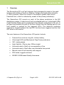
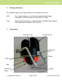
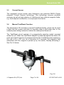
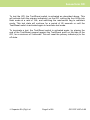
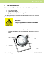
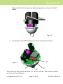
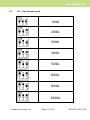
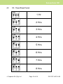
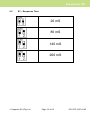
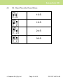
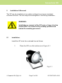
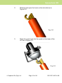
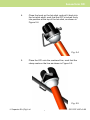
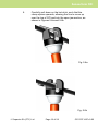
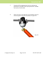
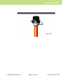
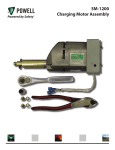
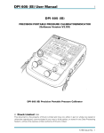
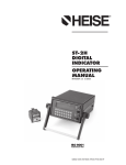
Sensorform Overhead Fault Indicator User Manual v1.0 Sensorform OFI CONTENTS SAFETY NOTICE ................................................................................. 3 1 OVERVIEW........................................................................................ 4 2 PRIMARY INDICATORS .................................................................... 5 3 DESCRIPTION ................................................................................... 5 3.1 3.2 3.3 3.4 4 USER SELECTABLE SETTINGS ....................................................... 9 4.1 4.2 4.3 4.4 5 S1 - TRIP CURRENT LEVEL ............................................................ 11 S2 – TIMED RESET PERIOD ............................................................ 12 S3 – RESPONSE TIME ................................................................... 13 S4 – RESET TIME AFTER POWER RETURN ......................................... 14 INSTALLATION & REMOVAL .......................................................... 15 5.1 5.2 6 PRIMARY INDICATORS .................................................................... 6 CONTROL CIRCUIT ......................................................................... 6 CURRENT SENSOR ......................................................................... 7 MANUAL TEST/RESET FUNCTION ...................................................... 7 INSTALLATION ............................................................................ 15 REMOVAL .................................................................................. 20 OPERATION .................................................................................... 22 6.1 6.2 6.3 6.4 FAULT DETECTION ...................................................................... 22 RESET ON POWER RETURN ............................................................ 22 MANUAL RESET .......................................................................... 23 TIMED RESET ............................................................................. 23 7 TESTING ......................................................................................... 24 8 SPECIFICATIONS............................................................................ 25 9 WARRANTY .................................................................................... 26 Suparule S$3W\ Ltd Page 2 of 28 OFI DCF1497 v0.02 Sensorform OFI Safety Notice Review the following safety precautions to avoid injury and prevent damage to this product or any products connected to it. PRECAUTIONS WARNING: Use extreme caution during the installation and use of the Sensorform OFI product as high voltages and currents may be present. Please read instruction information carefully. WARNING: Observe precautions for handling Electrostatic Sensitive Devices • This product must be installed and used only by qualified personnel that are familiar with practicing applicable safety precautions. • Wear necessary protective clothing and gloves as required. • Always inspect the OFI unit, for possible damage before installing the product. Do not use the product if damaged. • If the Sensorform OFI is not used in a manner specified, the protection afforded by the equipment may be impaired. • Static Electricity can damage sensitive electronic parts inside the unit. Any accumulated charge on the body of the human operator should be discharged first before opening the unit. The discharge can be accomplished by putting a hand on a grounded surface or, ideally, by wearing a grounded antistatic wriststrap. • The use of an antistatic strap prior to opening the unit is highly recommended. • Education and training on ESD preventive measures is recommended. Cleaning The Sensorform OFI unit is essentially a maintenance-free product. If the unit requires cleaning, it should first be disconnected from all hazardous voltage sources. The unit enclosure can then be wiped clean with a moist cloth. Ensure the unit is completely dry prior to reconnection. Suparule S$3W\ Ltd Page 3 of 28 OFI DCF1497 v0.02 Sensorform OFI 1 Overview The Sensorform OFI is a Fault Indicator that is designed to assist in the rapid location and isolation of faults on Medium Voltage overhead cable networks (1-38kV) systems. When the current in the phase is greater than the set threshold level, a fault is indicated by means of the primary indicator(s). The Sensorform OFI mounts on each of the phase conductors in the MV distribution system. A short-circuit fault is indicated both by 4 ultra-bright LEDs (Light Emitting Diode) and a mechanical Flag Indicator integrated in the unit. In an open-ring network the path of the fault current from the feeding point to the fault location is marked by the triggered OFI’s. The defective conductor segment is located between the last OFI that has been triggered and the first OFI which is still inactive. The main features of the Sensorform OFI product include: • Powered from internal, long-life, Lithium battery • Ultra-bright LED and Mechanical Flag Primary indicators • 360° viewing angle • High Visibility: 50m by day, 200m at night • Automatic reset of fault on re-energisation of line • Automatic reset of fault after user-selectable time period • Manual reset of fault remotely with magnet • IP65 rated, rugged enclosure • ISO9001:2008 based Quality Assurance Suparule S$3W\ Ltd Page 4 of 28 OFI DCF1497 v0.02 Sensorform OFI 2 Primary Indicators Two different types of primary indicator are included on the unit: LED: Four High-brightness, red, flashing Light Emitting Diodes, arranged in a circle around the unit for 360° visibility. Flag: Mechanical flag indicator, normally black, red/black when tripped, semi-spherical in shape for 360° visibility. 3 Description Conductor Jaw Enclosure Top Test/Reset Point Clamp LEDs Flag Eyelet Enclosure Base Suparule S$3W\ Ltd Page 5 of 28 OFI DCF1497 v0.02 Sensorform OFI The Sensorform OFI consists of the following components: 3.1 Primary Indicators Two different types of primary indicator are included on the unit: 3.2 LED: Four High-brightness, red, flashing Light Emitting Diodes, arranged in a circle around the unit for 360° visibility. Flag: Mechanical flag indicator, normally black, red/black when tripped, semi-spherical in shape for 360° visibility. Control Circuit This contains the necessary monitoring and detection circuits for detecting and validating fault as well as activating the fault indicator(s). Prior to installation, the user can set the following parameters via DIP Switches on the controller board inside the unit: • • • • Trip Current Level Timer Reset Period Auto-reset time after line re-energisation Fault response time The unit is mounted onto the overhead line using a hot-stick. The hot-stick is fixed to the eyelet on the underside of the unit. The unit is then brought up the overhead conductor. The clamp part of the unit is positioned above the conductor and let rest on the conductor. The unit is then manoeuvred in such away that the clamp is opened upwards sufficiently to allow the conductor to fall into the U-shaped section of the housing. Once this happens, the springmechanism of the clamp fixes the unit onto the line. The hot-stick can now be removed. The unit is designed to operate in the harsh environment of medium voltage overhead line networks (1 - 38kV). Suparule S$3W\ Ltd Page 6 of 28 OFI DCF1497 v0.02 Sensorform OFI 3.3 Current Sensor The integrated current sensor uses Suparule’s own patented PMCS (Planar magnetic Current Sensor) technology. This technology ensures excellent accuracy as well as high rejection of interference from external magnetic fields, e.g. from adjacent conductors, in an open-jaw form-factor. 3.4 Manual Test/Reset Function The Sensorform OFI includes a manual Test/Reset facility, which can be used to both test the system and also to manually reset a fault state prior to the network power being restored or before the reset-period times out. The Test/Reset circuit consists of a magnetically sensitive switch mounted inside the unit. When the Test/Reset Magnet is positioned against the side of th eunit such that th eend of th emagnet touches the Test/Reset point marked on the side of th e OFI unit, for a minimum of 3 seconds, the magnetic field associated with the magnet is picked up by the switch, thereby activating it. See Fig 3.4 below. Fig. 3.4 Suparule S$37<Ltd Page 7 of 28 OFI DCF1497 v0.02 Sensorform OFI To test the OFI, the Test/Reset switch is activated as described above. This will activate both the primary indicator(s) on the OFI, setting the four LEDs into flash mode at a rate of 1Hz, and switching the mechanical flag to red/black mode. This test state will continue for a period of 60 seconds or until the Test/Reset switch is activated again to terminate test mode. To terminate a test, the Test/Reset switch is activated again, by placing the end of the Test/Reset magnet against the Test/Reset point on the side of the OFI, for a minimum of 2 seconds. This will reset the primary indicator(s) to the off state. Suparule S$3W\ Ltd Page 8 of 28 OFI DCF1497 v0.02 Sensorform OFI 4 User Selectable Settings The Sensorform OFI unit allows the user to set the following parameters: • • • • Trip Current Level Timer Reset Period Auto-reset time after line re-energisation Fault response time The above parameters are set via DIP Switches mounted on the controller board inside the unit. WARNING: Observe precautions for handling electrostatic sensitive devices Access to the DIP switches is achieved by opening the unit as follows: 1. Unscrew and remove the four fixing screws as shown in Figure 4.1 below. 2. Fig 4.1 Suparule S$3W\ Ltd Page 9 of 28 OFI DCF1497 v0.02 Sensorform OFI Remove the Top Enclosure by sliding it upwards as shown in Fig 4.2 below. Fig. 4.2 3. Locate the row of DIP Switches as shown in Figure 4.3 below. S4 Fig. 4.3 S1 S3 S2 There are four sets of DIP switches, S1, S2, S3, and S4. The function of each set is as per the following: Suparule S$37< Ltd Page 10 of 28 OFI DCF1497 v0.02 Sensorform OFI 4.1 S1 - Trip Current Level 100A 200A 300A 400A 500A 600A 800A 1000A Suparule S$3W\ Ltd Page 11 of 28 OFI DCF1497 v0.02 Sensorform OFI 4.2 S2 – Timed Reset Period 1 Hr 2 Hrs 3 Hrs 4 Hrs 5 Hrs 6 Hrs 7 Hrs 8 Hrs Suparule S$3W\ Ltd Page 12 of 28 OFI DCF1497 v0.02 Sensorform OFI 4.3 S3 – Response Time 20 mS 80 mS 140 mS 200 mS Suparule S$3W\ Ltd Page 13 of 28 OFI DCF1497 v0.02 Sensorform OFI 4.4 S4 – Reset Time after Power Return 10 S 16 S 24 S 30 S Suparule S$3W\ Ltd Page 14 of 28 OFI DCF1497 v0.02 Sensorform OFI 5 Installation & Removal The OFI can be installed onto a medium voltage line using an insulated universal hot-stick. The line may be de-energised or live during installation. WARNING: Installation or removal of the OFI onto or from a live line should ONLY be carried out by suitably qualified and trained live-working personnel. 5.1 Installation Install the OFI onto the overhead line as follows: 1. Place the OFI on a flat surface as in Figure 5.1. Fig. 5.1 Suparule S$3W\ Ltd Page 15 of 28 OFI DCF1497 v0.02 Sensorform OFI 2. Release and open the hook on the hot-stick as in Figure 5.2. Fig. 5.2 3. Place the open hook into the eyelet at the base of the OFI as in Figure 5.3. Fig. 5.3 Suparule S$3W\ Ltd Page 16 of 28 OFI DCF1497 v0.02 Sensorform OFI 4. Close the hook on the hot-stick, and pull it back into the hot-stick shaft, such that the OFI is locked firmly into position at the top of the hot-stick, as shown in Figure 5.4. Fig. 5.4 5. Place the OFI onto the overhead line, such that the clamp rests on the line as shown in Figure 5.5. Fig. 5.5 Suparule S$3W\ Ltd Page 17 of 28 OFI DCF1497 v0.02 Sensorform OFI 6. Carefully pull down on the hot-stick, such that the clamp opens upwards, allowing the line to move up over the top of OFI and into the open jaw section, as shown in Figures 5.6a and 5.6b. Fig. 5.6a Fig. 5.6b Suparule S$37< Ltd Page 18 of 28 OFI DCF1497 v0.02 Sensorform OFI 7. Once the OFI is clamped onto the line, with the line positioned in the base of the open-jaw section, release the hook on the hot-stick. 8. Open the hook on the hot-stick, and carefully remove it from the eyelet on the OFI, as shown in Figure 5.8. Fig. 5.8 Suparule S$3W\ Ltd Page 19 of 28 OFI DCF1497 v0.02 Sensorform OFI 5.2 Removal To remove the OFI from the overhead line, carry out the following: 1. Bring the hot-stick, with hook extended and open, to the base of the OFI as shown in Figure 5.8 above. 2. Insert the hook into the eyelet on the base of the OFI, close the hook on the hot-stick, and pull it back into the hot-stick shaft, such that the hot-stick is locked firmly into position at the base of the OFI as shown in Figure 5.6b above. 3. Pull the hot-stick down carefully, such that the clamp opens, and frees the OFI from the overhead line, as shown in Figures 5.9 and 5.10 below. Fig. 5.9 Suparule S$3W\ Ltd Page 20 of 28 OFI DCF1497 v0.02 Sensorform OFI Fig. 5.10 Suparule S$3W\ Ltd Page 21 of 28 OFI DCF1497 v0.02 Sensorform OFI 6 Operation During normal operation, the unit is in standby mode. In this mode, the unit is drawing minimal current from its internal battery, in order to prolong the life of the battery as much as possible. All the time during in this standby mode, the unit is monitoring the level of current sensed by the current sensor. It is also monitoring the state of the magnetic switch. If a fault is detected or if the magnetic switch detects the Test/Reset Magnet, the unit reacts as follows: 6.1 Fault Detection The Sensorform OFI control unit continuously monitors the output signal from the integrated current sensor. In the event of a fault occurring, i.e. the level of current measured exceeds the Trip Current level DIP-switch setting and the fault is present for the minimum time period set by the Response Time DIPswitch setting, then the unit goes into fault mode and indicates the fault by switching the flag to Red/Black mode, and starting to flash the LEDs. The onboard circuitry analyses the voltage produced to determine that it is a valid earth fault signal as opposed to a transient spike or glitch. By ensuring the fault current is present for a minimum of the Response Time, all current spikes and glitches are ignored. The OFI unit will remain in fault mode until one of the following occurs: • • • 6.2 the power returns to the overhead line remote manual reset a time equivalent to the Timed Reset Period elapses Reset on Power Return In the case of the power returning to the line, this is detected by the current sensor measuring a current above the minimum nominal current level. After this has been the detected for a minimum time equivalent to that set by the Reset Time after Power Return DIP-switch setting, the unit resets. Suparule S$SW\ Ltd Page 22 of 28 OFI DCF1497 v0.02 Sensorform OFI 6.3 Manual Reset The unit can be manually reset from the fault mode by activating the internal magnetic switch. This is done by fixing the Test/Reset Magnet to the top of a hot-stick and positioning the end of the magnet to the Test/Reset point indicated on the side of the OFI unit, for a minimum of 2 seconds. (See Fig 3.4 above). The magnetic field from the magnet is detected by the magnetic switch mounted on the controller board inside the OFI, causing it to reset. 6.4 Timed Reset If neither the network power returns, nor a Manual Reset is implemented, the OFI unit will remain in the fault mode for a duration set by the Timed Reset Period DIP-switch setting, after which it will reset. Suparule S$3W\ Ltd Page 23 of 28 OFI DCF1497 v0.02 Sensorform OFI 7 Testing To check the trip current level of the Sensorform OFI the following test should be conducted: 1. Mount the unit on a conductor connected to an AC Current Source. 2. Generate a fault current in the conductor less than 90% of the current level set by the Trip Current Level DIP-switch setting. For example, for the trip current level of 100A, set the fault current to less than 90A. This should not trip the unit. 3. Generate a fault current greater than 110% of the current level set by the Trip Current Level DIP-switch setting, (e.g. for a trip current level of 100A, set the fault current to more than 110A) for a period of 1 second or more. This should trip the unit. 4. Reset the unit using by positioning the Test/Reset Magnet close to the side of the OFI unit. Suparule S$3W\Ltd Page 24 of 28 OFI DCF1497 v0.02 Sensorform OFI 8 Specifications Trip current: Minimum fault duration: Primary Indication: Fault LED Indicator Flash Rate: Reset of Fault: User-Selectable from 100, 200, 300, 400, 500, 600, 800 or 1000 A, +/- 10% User-Selectable from 20, 80, 140, or 200 mS, +/- 20% Four High Intensity Red LEDs and Red/Black Flag, both with 360° visibility. 0.5 Hz Automatic after a user-selectable time of 10, 16, 24, or 30 seconds after power return or remote Activation of Manual Reset or after user-selectable period of 1, 2, 3, 4, 5, 6, 7 or 8 hours. Network voltage range: Conductor Size Range: Fault current withstand: Operating temperature range: Operating humidity range: Ingress Protection: Altitude: 1-38kV AC 8 - 25mm diameter 25kA for 1s -20ºC to +70ºC 0 - 100% RH IP65 5000 meters Dimensions: Diameter: 115 mm Height: 165mm Polycarbonate Spring-loaded aluminum clamp 750g Enclosure Material: Mounting: Weight: Suparule S$3W\ Ltd Page 25 of 28 OFI DCF1497 v0.02 Sensorform OFI 9 Warranty Suparule Systems Limited (‘The Company’) warrants that the product is free from defects in materials and workmanship for a period of twenty-four months (24) from the date of shipment. Where defects occur in materials and / or workmanship during the twenty-four month period from date of shipment The Company will correct such defects and the correction shall be in the form of repair or replacement of the defective items or components Such correction shall constitute a fulfillment of all of The Company’s liabilities in respect to said items and components. In no event shall The Company be liable for consequential damage. Exclusions under the Warranty 1 Normal Wear and Tear. Periodic maintenance, repair and replacement of parts due to normal wear and tear are excluded from coverage. 2 Abuse & Misuse. Defects or damage that result from: (a) improper installation operation, storage, misuse or abuse, accident or neglect, such as physical damage (cracks, scratches, etc.) to the surface of the product resulting from misuse; (b) contact with hazardous substances; or (c) other acts which are not the fault of The Company, are excluded from coverage. 3 Altered Products. Products or Accessories with (a) serial numbers or date tags that have been removed, altered or obliterated; (b) broken seals or that show evidence of tampering or misuse of the electronics are excluded from coverage. Suparule S$3W\ Ltd Page 26 of 28 OFI DCF1497 v0.02 Sensorform OFI No Other Warranties To the maximum extent permitted by applicable law in the Republic of Ireland, The Company disclaims all other warranties, either express or implied, including but not limited to implied warranties of merchantability and fitness for a particular purpose, with respect to the Sensorform OFI product and the accompanying product documentation. Disclaimer To the maximum extent permitted by the laws applicable in the Republic of Ireland, in no event shall Suparule Systems Ltd. be liable to the user for any special, indirect, consequential or similar damages, including any loss of profits or lost data arising out of the use or inability to use the product or documentation. Suparule S$3W\ Ltd Page 27 of 28 OFI DCF1497 v0.02 Sensorform OFI Suparule S$3W\ Limited 6LPED6WUHHW 6HEHQ]D (GHQYDOH *DXWHQJ 6RXWK$IULFD HPDLOVDOHV#VXSDUXOHFR]D Tel: + (0) )D[ HPD www.suparule.co]D Suparule Systems Ltd Page 28 of 28 OFI DCF1497 v0.02