1
ST-2H
DIGITAL
INDICATOR
OPERATING
MANUAL
REVISION 4.3 3/2004
I&M002-10091-(HST-MAN) 1P6/00 4P7/06 250 SP
Thank you for your purchase. Please feel free to contact us if we may be
of assistance in any way.
Should you require service for this instrument or wish to take advantage
of our expert factory recalibration services, please complete the material
return form which can be printed directly from the “service” button on
the Heise website. Please return the instrument to:
Ashcroft Inc.
250 East Main Street
Stratford, CT 06614-5145, USA
Tel: (203) 378-8281
Fax: (203) 385-0402
For the latest return form and product
information, please visit our website at:
www.heise.com
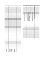
Table of Contents
Section
Description
1.0
Introduction ...............................................................................................................................
4
Base Unit Overview .......................................................................................................
Quick Select Module Overview .....................................................................................
The GQS-1 Quick Select Pressure Module ...............................................................
The GQS-2 Quick Select Pressure Module ...............................................................
The GQS-RT Quick Select RTD Temperature Interface Module ..............................
The GQS-TC Quick Select Thermocouple Module ..................................................
4
4
5
5
5
6
2.0
Unpacking ..................................................................................................................................
6
2.1
2.2
2.3
Unpacking Product Upon Receipt ..................................................................................
Product Storage ..............................................................................................................
Product Cleaning ............................................................................................................
6
6
6
3.0
System Start-Up General Instructions ....................................................................................
6
1.1
1.2
1.2.1
1.2.2
1.2.3
1.2.4
3.1
3.2
3.3
3.4
3.5
3.5.1
3.5.2
3.5.3
3.5.4
3.5.5
3.6
Page
Power Cord Connection ................................................................................................. 6
Battery Installation ......................................................................................................... 6
Installation of Quick Select Modules ............................................................................. 7
Starting Up MDI Indicator System ............................................................................... 8
Optional System Start Up Procedures ............................................................................ 8
Auto Off- Battery Save Function .............................................................................. 9
Battery Life Overview ............................................................................................... 9
Low Battery Icon ....................................................................................................... 9
Programming Date and Time Information ................................................................ 10
Input of Owner/Operator Information ....................................................................... 10
Removing Quick Select Modules ................................................................................... 12
4.0
Key Function Overview ............................................................................................................. 12
5.0
Port Select Function ................................................................................................................. 13
6.0
Zero Function ............................................................................................................................ 13
6.1
Zeroing One of Two Installed Quick Select Pressure Module ....................................... 14
7.0
Displaying Current & Voltage Measurements ......................................................................... 14
8.0
Engineering Unit Selection ....................................................................................................... 14
8.1
8.2
8.3
8.4
8.5
Selecting a Factory Programmed Engineering Unit .......................................................
Setting Up a Custom (User Defined) Engineering Unit .................................................
Using a Custom (User Defined) Engineering Unit.........................................................
Display of Two Different Engineering Units,
for Two Installed Modules .........................................................................................
Temperature Selection for H2O Conversion Factor ........................................................
15
15
16
17
18
9.0
Tare Function ............................................................................................................................. 18
10.0
Hold Function ............................................................................................................................ 19
10.1
Using the Hold Function ................................................................................................ 19
11.0
Minimum and Maximum Value Tracking .................................................................................. 19
-3-
Revision 4.3
3/2004
Section
Description
12.0
Damping Function ..................................................................................................................... 20
12.1
12.2
Set Up of Damping Function ......................................................................................... 20
Activating or Discontinuing Damping ........................................................................... 20
13.0
Percent Function ....................................................................................................................... 21
13.1
13.2
Set Up of Percent Function ............................................................................................ 21
Use of Percent Function ................................................................................................. 22
14.0
Flow Velocity and Flow Volume Measurement Background .................................................. 22
14.1
14.2
14.3
14.4
14.5
14.6
Page
Set Up for Flow Velocity & Volume Measurement ........................................................
Flow Velocity Measurement ...........................................................................................
Engineering Unit Selection for Flow Velocity ...............................................................
Flow Volume Measurement ............................................................................................
Engineering Unit Selection for Flow Volume ................................................................
Simultaneous Display of Two Flow Measurements in
Independent Engineering Units .................................................................................
Simultaneous Display of Flow (Velocity or Volume)
with a Pressure Measurement ....................................................................................
Simultaneous Display of Flow (Velocity or Volume)
with a Temperature Measurement .............................................................................
Simultaneous Display of Flow Volume and Flow Velocity ............................................
Simultaneous Display of Flow (Velocity or Volume) and An
Electrical Output Measurement .................................................................................
14.7
14.8
14.9
14.10
23
23
24
24
25
25
26
27
27
28
Leak Detection Function ........................................................................................................... 29
15.0
15.1
15.2
15.3
Leak Rate Function Set Up ............................................................................................
Pressure Decay Function Set Up ....................................................................................
Module Selection for Performing Leak Rate or Pressure
Decay Tests ................................................................................................................
Performing Leak Rate or Pressure Decay Tests .............................................................
15.4
29
29
30
30
16.0
Temperature Measurement Using RTD Probes ...................................................................... 31
16.1
16.2
Setting Up the Calibrator for Temperature Measurement
with an RTD Probe .................................................................................................... 31
Calibrating and Programming of the RTD Interface and Probe ..................................... 33
17.0
Temperature Measurement Using Thermocouple .................................................................. 33
17.1
Setting Up Calibrator for Temperature Measurement
with a thermocouple .................................................................................................. 33
18.0
Pressure and Temperature Switch Testing .............................................................................. 35
18.1
18.2
18.3
Setting Up for Pressure and Temperature Switch Testing .............................................. 35
Trip Point Testing ........................................................................................................... 35
Deadband Testing ........................................................................................................... 36
19.0
RS232 Interface ......................................................................................................................... 37
19.1
19.2
19.2.1
19.2.2
19.2.3
19.2.4
Revision 4.3
Configuring RS232 Interface for Use With Dumb Terminal..........................................
RS232 Configuration Options ........................................................................................
RS232- ISO1745 Mode Functional Overview .........................................................
RS232- Journal Mode Functional Overview ............................................................
RS232- Interface Inquiry Mode Functional Overview ..............................................
RS232-Interface Remote Mode Operation ................................................................
3/2004
-4-
37
37
37
38
38
38
Section
Description
19.0
RS232 Interface (Continued)
19.3
19.4
Page
RS232 Set Up for Journal Mode Operation ................................................................... 38
RS232 Set Up for Inquiry Mode Operation ................................................................... 40
20.1
20.2
................................................................................................................................. 41
Reviewing Instrument Status .......................................................................................... 41
Battery Check Function .................................................................................................. 41
21.0
Dual Module Functions ............................................................................................................. 42
21.1
21.2
21.3
Accuracy of Dual Module Measurements ...................................................................... 42
Setting Up Dual Module Differential Pressure Measurement........................................ 43
Setting Up a Dual Module Summation Pressure Measurement ..................................... 44
22.0
22.1
Data Logging Function (Optional) ........................................................................................... 45
20.0
22.2
22.3
22.4
22.5
22.6
22.7
22.8
Status
Sequential Data Logging ................................................................................................
Setting Up the Data Logging Function ..........................................................................
Data Labeling Function ..................................................................................................
Automatic Data Logging ................................................................................................
Manual Data Logging.....................................................................................................
Review of Stored Data on display ..................................................................................
Erasing of Selected Stored Data .....................................................................................
Erasing All Stored Data ..................................................................................................
45
45
46
46
47
48
49
50
23.0
Data Logging with Cert Generation Firmware ........................................................................ 50
23.1
Set Up and Use of Certification Generation Data Logging ............................................ 50
24.0
Connection of MDI to Computer for Upload of Stored Calibration Data .............................. 55
24.1
24.2
Installing and Operating Upload Software Utilities ....................................................... 56
Replacement of Data Logging Memory Back-up Battery ............................................. 56
25.0
Event Timer Function (Requires Data Logging Option .......................................................... 57
25.1
25.2
Event Timer Set Up ........................................................................................................ 57
Data Logging Set Up for Event Timer Operation .......................................................... 58
26.0
Alarm Function Overview ......................................................................................................... 59
26.1
Alarm Set Up and Operation .......................................................................................... 59
27.0
Recertification of the MDI Indicator ......................................................................................... 60
27.1
27.2
27.3
27.4
27.5
27.6
Access Codes..................................................................................................................
Calibration/Recertification Overview .............................................................................
Required Equipment .......................................................................................................
As Received Readings-Base Unit Electronics ................................................................
Adjustment and Calibration Base Unit Electronics........................................................
Quick Select Pressure Module Recertification ...............................................................
60
61
61
61
62
65
APPENDICES
Appendix A –
Appendix B –
Appendix C –
Appendix D –
Appendix E –
Appendix F –
Pressure Conversion Factors ......................................................................................................
ASCII Character Set .....................................................................................................................
Product Specifications ...............................................................................................................
Serial Communications – Remote Mode ...................................................................................
RTD Probe Connector .................................................................................................................
Certification of the TC1 Thermocouple Interface Module ........................................................
-5-
Revision 4.3
69
70
73
76
79
80
3/2004
Section 1.0
Introduction
twelve factory programmed or one operator designated
engineering unit. Temperature measurement data can be
displayed in degrees Celsius, Fahrenheit, Kelvin or Rankine. In addition, when used with the GQS-RT1 Quick
Select module for temperature measurement with an
RTD temperature probe, the MDI system can display the
RTD measurement in ohms. GQS-TC1 modules allow
the display of the same temperature units as well as millivolts In addition to displaying two pressure measurements simultaneously the operator can elect to display
pressure and temperature or the measured value from
either of the two installed Quick Select modules as well
as either a voltage or mA measurement. This allows for
the easy calibration and test of transducers, transmitters
and switches.
Congratulations! Your purchase of the Modular Digital Indicator (MDI) calibration system equips you to
perform a wide variety of pressure and temperature
measurements. The general pressure and temperature
measurement capabilities of the MDI measurement
system are supplemented by application specific firmware as well as the availability of optional data logging
capability.
.
The MDI products are complete pressure calibration
systems providing: interchangeable pressure ranges,
simultaneous measurement and display of two pressure
ranges, measurement and display of current and voltage.
The MDI system also provides the ability to perform
high accuracy temperature measurement. Conversion
between temperature and pressure measurement can be
done in a matter of seconds and requires no tools.
The base unit includes a wide variety of general and
application specific measurement capabilities. These
capabilities allow the MDI measurement and calibration
system to be used for basic pressure and temperature
measurement as well as application specific pressure
measurement activities. Basic pressure and temperature
measurement capabilities include; max/min recall, operator programmable tare values, display hold, operator
programmable damping and user selected engineering
units. Application specific capabilities include; flow
velocity measurement, flow volume measurement, leak
detection, leak rate quantification and switch testing.
Optional data logging, time delayed data logging and
programmable alarms are also available.
A standard MDI system consists of a base unit that acts
as a host for one or two Quick Select modules. The
Quick Select pressure modules are interchangeable
and are available in a wide variety of ranges from 0.25
inches of water to 10,000 psi. A brief description of the
main components of an MDI system follows. In addition, Quick Select modules are available that allow the
base unit to work in conjunction with most any standard
RTD temperature probe or thermocouple.
Section 3 and its various subsections include all the information needed to begin using the MDI system for basic pressure and temperature measurement. Higher level
functions are detailed in later sections of this manual. It
is strongly recommended that the pertinent sections of
this manual be reviewed prior to using the MDI system
for higher level and application specific measurement
and test activities.
Section 1.2
The Quick Select pressure module is a calibrated pressure measurement device. Quick Select pressure module
units are available in a wide variety of pressure measurement ranges. Quick Select interface modules are also
available to allow the MDI base unit to provide precision
temperature measurement data using standard RTD (Resistance Temperature Detector) and thermocouple detector temperature sensing devices. The GQS-RT1 module
allows the MDI system to function with most common
platinum, nickel and copper RTDs and the GQS-TC supports use of thermocouple temperature detectors.
Important: Failure to follow the instructions provided in
this manual may result in personal injury and/or damage to the instrument, accessories, products under test or
other equipment.
Section 1.1
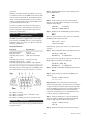
Base Unit Overview
The base unit functions as the host for the Quick Select
pressure and temperature modules designated in this
manual by the “GQS” prefix. Each base unit includes a
keypad, microprocessor based electronics and a two line
LCD display. The base unit displays the measurement
data transmitted from the Quick Select module(s).
Measurement outputs from two installed Quick Select modules can be simultaneously displayed. Quick
Select modules for the measurement of either pressure or temperature can be plugged into either of the
2 module “bays” in the base unit. Pressure engineering
units can be independently selected from the library of
Revision 4.3
3/2004
Quick Select ModulesOverview
The Quick Select module communicates with the base
unit via a 10 pin connector. Quick Select pressure modules slide into the base unit automatically aligning the
female 10 pin connector on the Quick Select pressure
module with the male 10 pin connector in the base unit.
All calibration data is stored in Electrically Erasable
Programmable Read Only Memory (EEPROM) resident
in the Quick Select module. As such, any Quick Select
module can be used in any base unit and the measurement system will provide measurement accuracy in
conformance with the published specification.
-6-
Section 1.2.1
The GQS-1 Quick Select
Pressure Module
orientation. When positioned in this fashion, the output
will be near zero when no pressure (stress) is applied
and will increase in a near linear fashion with the application of pressure or vacuum. The reverse side of the
substrate is etched to provide the required diaphragm
thickness for the given pressure range.
GQS-1 Quick Select pressure modules provide specialized low pressure measurement capabilities. GQS-1
Quick Select pressure modules incorporate a micro-machined silicon variable capacitance module.
When power is applied to the module the level of resistance across the wheatstone bridge will change in proportion to the level of pressure applied. The output from
the module is extremely repeatable and has minimal
hysteresis due to the fact that the module substrate is
silicon. The module output is then amplified by circuitry
within the Quick Select pressure module. The amplified output is then calibrated over the operating range of
the module. Calibration coefficients for the module are
stored in Electrically Erasable Programmable Read Only
Memory (EEPROM) within the Quick Select pressure
module.
Inside the module there is a micro-machined silicon
diaphragm. This diaphragm is between two non-moving plates on which metal has been sputtered. The air
between the diaphragm and the non-moving plates acts
as an insulator.
As pressure or vacuum is applied to the module, the
diaphragm moves changing the distance between the
diaphragm and the fixed plates. This change in distance
changes the capacitance of the module. It is this variable
capacitance that is measured and correlated to pressure
or vacuum during the calibration process.
The module is connected to a circuit board that generates a linear signal ramp and applies this signal to the
top plate of the module while an equal and opposite
signal is applied to the bottom plate.
GQS-2 modules are available in ranges from 5 through
10,000 psi. These modules can be configured to provide
gauge, compound or absolute pressure measurement,
as well as vacuum measurement capabilities. GQS-2
modules in range of 5 psi are designed for use on clean,
dry, noncorrosive and nonconductive gases. 316 stainless
steel module isolation is provided for ranges from 0/10
through 0/10,000 psi.
When the measured pressure is balanced, for example,
when both ports are opened to atmosphere, the distance
between the diaphragm and both of the fixed plates is the
same. When this is the case, the signal to the top plate
is capacitively coupled to the equal and opposite signal
applied to the bottom plate. As a result, no signal current
will flow through the center plate (diaphragm). When
the diaphragm is moved off center by the application of
pressure or vacuum, the excess current flows through
the center plate to an input differentiator on the circuit
board. The differentiator translates the frequency of the
module output into a voltage which is scaled over the
full scale range of the module.
Section 1.2.3
The GQS-RT1 allows the MDI base unit, when used
with RTD temperature probes, to provide precision
temperature measurement data. The GQS-RT1 plugs
directly into the Quick Select module bay in the base
unit. Any standard RTD probe with a Switchcraft TA4M
connector can be plugged into the Switchcraft TA4F
connector on the module.
GQS-1 modules are available in ranges from 0.25 inches
of water through 200 inches of water. These modules
can be configured to provide differential/gauge or
compound pressure measurement capabilities. They are
designed for use on clean, dry, noncorrosive and nonconductive gases.
Section 1.2.2
The GQS-RT Quick Select RTD
Interface Module
The GQS-RT1 module comes factory programmed
with the curves for Pt 100 (385 & 392), Cu 10 and Ni
120 RTD probes. It supports RTDs with outputs in the
range of 0/400 ohms. The GQS-RT2 is supplied factory
programmed to support the Pt1000 ( 385 & 392) RTD.
This module will support RTDs through an output up to
4000 ohms. The GQS-RT module can be programmed
with coefficients for other RTD probes of interest and
specific characteristics of a probe already included in the
on-board library can be programmed into the GQS-RT
unit to provide enhanced accuracy.
The GQS-2 Quick Select
Pressure Module
The GQS-2 Quick Select pressure module incorporates
a micro-machined piezoresistive strain gauge module.
This technology takes advantage of the fact that, when
put under stress, (as with the flexing of a diaphragm
under pressure or vacuum) the resistive properties of
a piece of silicon will change. In the manufacturing
process resistors are deposited in a silicon substrate. The
resistors are typically configured in a wheatstone bridge
Each GQS-RT module can accommodate up to 8 different programmed RTD calibration curves. Programming
of the RT module is accomplished via an optional software package and any PC compatible computer with an
available standard serial communication port.
-7-
Revision 4.3
3/2004
Section 1.2.4
The GQS-TC1 Quick Select
Thermocouple Interface Module
Section 3.1
The MDI system is powered via standard 110 Vac, 60 Hz,
230 Vac, 50 Hz or 100 Vac, 60 Hz line power. The line
power is adapted to meet the 9 Vdc power requirements
of the MDI system via a standard outlet mounted voltage
adapter.
The GQS-TC1 allows the base unit, when used with a
thermocouple interface module, to perform temperature
measurement. The GQS-TC1 plugs directly into the
Quick Select module bay in the base unit. The thermocouple is then attactched to the GQS-TC1 module via a
male “miniature thermocouple connector.”
Section 2.0
The adapter plugs into the round receptacle located in the
center of the back panel, over the 9 pin RS232 connector.
Unpacking & General Care
Step 1 Plug adapter into the receptacle in the center of
the back panel of the MDI instrument over the RS 232
connector.
General instructions on unpacking and care follow.
Section 2.1
Unpacking Product Upon Receipt
Step 2 Plug the side with the adapter mounted in the
Prior to removing the MDI Digital Indicator System from
the packaging material inspect all cartons for shipping
damage. Document any damage evident in the event that
a damage claim must be made against the shipper. After
inspection, remove the base unit, module(s), manual and
any accessories purchased from the packaging material.
Retain the packaging for use in returning the MDI to the
factory for future recertification or repair.
Section 2.2
appropriate wall outlet.
Step 3 To operate the unit simply press the ON/OFF
key with the system connected as outlined in steps 1 and 2.
Section 3.2
MDI indicators are available in two optional configurations for portable operation. These options are:
1 – Rechargeable nickel cadmium power pack.
2 – Battery holder that supports the use of five AA alkaline, zinc and non-rechargeable batteries.
Product Cleaning
The enclosure of the MDI system is not watertight. As
such, care should be taken during cleaning to assure liquid
does not penetrate the enclosure for the base unit or Quick
Select modules. Cleaning of the product should be done
with a cloth moistened with a warm, mild detergent mixture.
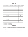
Section 3.0
Battery Life*
3/2004
Time in Hours
AA
NiCad
Alkaline Pack
48
20
Standard Operation
Total available time with:
Backlight on
Optional Loop supply (no load)
Optional Loop supply (12mA load)
Backlight & loop supply (no load)
Backlight & loop supply (12 mA load)
System Start-Up General Instructions
The MDI system can perform a wide variety of simple
and complex temperature and pressure based measurement, test and calibration operations. Due to the menu
driven set up procedures the system can be quickly and
easily configured for most any of its measurement functions. By following the steps in this section you can be
ready to use your MDI system to perform basic pressure
and temperature measurement functions in a matter of
minutes.
Revision 4.3
Battery Installation (Optional)
Product Storage
The product should be stored in an area that is maintained
in the temperature range indicated in the storage temperature in the product specification. The storage temperature limits are –4 to + 158 degrees Fahrenheit. Storage of
product in environments that will exceed these temperature limits results in significant risk of product damage. It
is recommended that the product not be left in closed cars
or truck cabs as temperature damage can easily occur due
to the “greenhouse effect” of closed vehicles or extreme
cold temperatures that can result from winter conditions.
Section 2.3
Power Cord Connection
4.5
24
9
4
3
3.25
10
4.5
2.
2
*Battery life figures are estimates based on instrument operation at a
nominal temperature of 70 degrees Fahrenheit. Use of the MDI product
at temperature significantly greater than or less than 70 degrees Fahrenheit will adversely effect battery life.
Battery installation and replacement is detailed in this
section.
-8-
Step 1 To gain access to the battery compartment, turn
the unit bottom side up.
pack. Used pack should be treated as hazardous waste
and forwarded to a recycling facility.
Step 2 Open the battery compartment by turning the
Step 12 Connect the replacement battery pack and place
quarter turn screw in the battery compartment door.
the pack in the battery compartment.
Step 3 With the screw no longer engaged to the main
Step 13 Replace battery compartment cover by sliding
case lift the door, screw end first, and slip the opposite
end of the door out of its slots.
cover back into position and securing the screw.
Battery installation/replacement is now complete.
Charge batteries 16 hours prior to initial operation
For MDI units designed for use with non-rechargeable
battery types proceed to step 4. For MDI units designed
for use with the NiCad power pack skip to Step 9.
Section 3.3
Installation of Quick Select
Module in Vacant Module Bay
Step 4 Note polarity information for battery instal-
lation is diagrammed inside the battery enclosure.
Step 5 Remove the retaining clips over each of the
battery compartments by inserting a small screwdriver in
each end of the clips and flexing the end clip away from
the battery. With the clip flexed outward, left the retainer
up. Repeat the process for the other side of the retainer
clip. Remove each of the five (5) clips in this fashion.
Step 6 Locate the five AA replacement batteries to be
Caution: Quick Select modules should be installed with
the power off on the base unit. Failure to turn the base
unit off prior to changing pressure measurement modules could damage the instrument or module electronics or “lock up” microprocessor operation. If power is
inadvertently left on and the base unit locks up (looses
communication) after changing Quick Select modules,
simply power down the unit and restart. Refer to Section
3.6 for the procedure to remove a Quick Select module.
used. Install these batteries as shown on the diagram in
the battery enclosure.
Step 7 Reinstall the five (5) battery retaining clips
by placing over the battery and pressing each end until
locked in position.
Step 8 Replace battery compartment cover by sliding
cover back into position and securing the screw.
Step 9 Rechargeable Nickel Cadmium Power Pack
To insert a Quick Select module follow the process
below.
Replacement
*** WARNING ***
Step 1 Make certain the power is off on the base unit.
The MDI system, when equipped with the rechargeable
battery operation option, includes automatic built-in
charging circuitry. This charging circuit will automatically charge the battery pack whenever the MDI system
is operated off line power. Due to this, MDI instruments with this option, must only be used with nickel
cadmium battery pack provided by your MDI supplier.
Modification of the system for use with other battery
packs or non-rechargeable battery types such as alkaline
batteries will cause risk of personal injury, instrument
damage and explosion.
Step 2 Hold the base unit, in one hand, with the back
end of the MDI system facing the operator.
Step 3 Holding the Quick Select module to be installed
in the other hand, align the module with the locking tab
toward the outer edge of the instrument on the side the
module is to be installed. (The manifold and labels will
be perpendicular to the bottom of the instrument).
Step 4 Slide the Quick Select module into the module
With the battery enclosure open locate and lift out the
battery pack assembly.
base until the retaining/release tab, the black push tab,
pops out the side of the MDI instrument case. When the
black tab/push button pops out the module is locked into
position.
Step 10 Grasp the connector across the narrow sides and
Step 5 Installation of the Quick Select module is now
press on the clip mechanism to release the connector.
complete. If an GQS-RT1 RTD interface module is to be
used, plug the desired RTD probe into the connector on
the Quick Select Module. To set up the MDI and GQSRT1 combination to the desired measurement parameters
proceed to Section 16.
Step 11 While pressing on the clip, with constant even
pressure, pull the connector outward.
Important Note: Do not throw away the spent battery
-9-
Revision 4.3
3/2004
Important Notes:
on the module label. The information on the left side of
the display corresponds with the Quick Select module
installed in the left module bay and information on right
side of the display corresponds with the Quick Select
module installed in the right module bay. If only one
module is installed the corresponding side of the display
will indicate “no module” on power up.
1 – Process connections to the module should: be made
using teflon tape or similar sealant, be tested at low
pressure prior to applying elevated pressures and
should be tightly secured using proper tools.
2 – If only one module is to be used, install the Quick
Select System Protection module provided. Follow
the same procedure to install the system protection
module as that used for a standard pressure
measurement module. Both module bays of the base
unit should contain a Quick Select module to protect
from dirt or other debris getting into the base unit
assembly. If only one Quick Select pressure module
is needed install the System Protection Module (part
number GQS-XS) supplied with your unit at the time
of shipment when using the MDI system.
Section 3.4
After the third screen the MDI system will commence
providing measurement data. The format for display of
the measurement data is as follows:
Eng Unit Eng Unit
(primary engineering unit)
+xx.xxx +xx.xxx
(measured value with sign)
When only one module is installed, the side of the display corresponding to the side of the base unit that does
not have a module will display “- - - - -”
Starting-Up the MDI System
After the desired Quick Select pressure module(s) or
Quick Select temperature measurement interface module
and probe has been installed the MDI System can be
started up as follows with the unit plugged in or with the
optional nickel cadmium batteries charged:
If necessary, the MDI system, used with a Quick Select
pressure module, may be zeroed by pressing the Zero
key prior to beginning measurement activities. Additional details on zeroing the MDI system are provided in
Section 6.0 of this manual.
Turn the system power on by pressing the on/off key on
the instrument’s key pad.
The MDI system is now ready for basic pressure or
temperature measurement. Simply connect the pressure
port(s) of the Quick Select pressure module(s) to be
used to the pressure source to be measured. If a gauge
pressure measurement is to be made using a differential Quick Select pressure module be sure to connect
the pressure to be measured to the high pressure port
on the Quick Select pressure module. For temperature
measurement, connect the RTD probe to be used to
the Switchcraft connector on the interface module and
proceed to Section 16.1 for instructions on setting up the
MDI system for temperature measurement.
ON
OFF
During the start up process the MDI will display a
series of start-up screens that:
• identify the type of module in each bay
• identify the range of each installed
• module (ohms range for GQS-RT modules)
• indicate that the installed module (pressure
only) has been calibrated with enhanced temperature
performance. (consult specification sheet for detail on
this capability)
Section 3.5
After the start-up routine is complete the MDI will display: (for base with two pressure modules installed)
There are additional set up operations that can be performed to increase the overall capabilities of the MDI
system; these include:
Range
Range
xx EngUnit xx EngUnit
1 – Auto off function to protect from inadvertently leaving the MDI system on and depleting
batteries in
systems equipped with the nickel cadmium or alkaline
battery option.
The range indication is provided in the primary engineering unit for each installed Quick Select module.
Upon initial power up an MDI base unit used with an
GQS-RT1 temperature module and probe will default
to displaying the ohms (resistance value) for the probe.
Once set up this combination will default to the previously used temperature measurement unit, such as
Celsius, Fahrenheit, Kelvin or Rankine. The primary
engineering unit for a given Quick Select pressure
module, along with the measurement range, is included
Revision 4.3
3/2004
Optional System Start Up
Procedures
2 – Setting up battery level indication so that an estimate
of the remaining battery life can be viewed at
the push of a button. Alkaline only see section 3.5.2 for
details.
3 – Programming the date and time for use in date
stamping data logged measurements and for initiat-
-10-
ing time delayed data logging on MDI units with the
optional data logging capability. Current date and time
information is only maintained in units with the data
logging option.
The battery save mode selected is stored in Electrically
Erasable Programmable Read Only Memory (EEPROM). As such it does not require reprogramming on
power up.
4 – Programming owner/operator information for
display on the MDI to facilitate tracking of in-house
instrumentation.
Section 3.5.2
The MDI indicator is available with a choice of built-in
battery power options. These are:
The following subsections provide information on the
above listed start up procedures.
Section 3.5.1
Battery Life of Optional Battery
Power Feature
1 – Five AA alkaline batteries (non-rechargeable)
Auto Off – Battery Save Function
(BatSave)
2– Built-in NiCad power pack and charging circuitry.
T he two options are mutually exclusive and must be
specified at the time of order. The life expectancy of the
two battery types is different and is detailed below.
The MDI system can be set up to automatically turn
itself off if no keypad activity is detected for a 10 minute
time period. This capability will protect MDI system
being powered off the optional nickel cadmium batteries
from accidental depletion of the batteries.
Battery Life*
Time in Hours
AA NiCad
Alkaline Pack
The following procedure is used to activate or disable
the battery save function.
Standard Operation
Step 1 With the MDI system on and reading pressure
press the SET UP key.
Backlight on
Optional Loop supply (no load)
Optional Loop supply (12mA load)
Backlight & loop supply (no load)
Backlight & loop supply (12 mA load)
SET
UP
Step 2 Using the arrow keys select the battery save
function (designated BatSave in the set up menu). When
selected, the text “BatSave” will flash.
BatSave
UserEng
48
20
4.5
24
3.25
10
9
4
3
4.5
2.5
2
Total available time with:
* Battery life figures are estimates based on instrument operation at a
nominal temperature of 70 degrees Fahrenheit. Use of the MDI product at temperature significantly less than 70 degrees Fahrenheit will
adversely effect battery life.
PerCent
H2Oref
Important Note: Due to the extreme variation in battery
life under different operating conditions (backlight on
or off or loop supply in use, it is recommended that the
battery voltage value be used to determine when replacement of batteries is warranted.
Step 3 With the “BatSave” text flashing press the
enter key.
ENT
Step 4 Using the left or right pointer select Disable or
Enable, as desired. When selected the text will flash.
Section 3.5.3
Auto shut off
Disable
Enable
Low Battery Icon
The MDI System provides advanced warning of a low
battery condition. The low battery warning icon, which
looks like a miniature battery will flash in the center of
the top line of the display when the measured battery
voltage drops to 5.6 Vdc. The MDI system will continue
to function properly with the low battery icon flashing.
Step 5 With the word “Enable” flashing press enter to
activate the battery save function.
ENT
If Enable is selected the MDI system will automatically
turn off if there is no keypad activity detected for a
period of 10 minutes. If Disable is selected the MDI system will remain on continuously as long as an adequate
power supply is available. The system, if being operated
off the nickel cadmium batteries, will continue operation
until the battery voltage is no longer sufficient to power
the system.
To ensure uninterrupted measurement capability it is
recommended that the batteries be recharged (NiCad)
or replaced (alkaline) as soon as possible after the low
battery icon appears. When the measured voltage drops
to 5.4 Vdc, the low battery icon will flash on the display
and the MDI system will turn itself off after 15 seconds.
If the measured voltage drops below 5.2 Vdc the MDI
system will not allow power up.
-11-
Revision 4.3
3/2004
Summary of low battery warnings:
HH =
5.6 Vdc: Low battery icon appears
5.4 Vdc: Low battery icon remains on display,
unit powers down after 15 seconds.
5.2 Vdc: Power up not allowed
where:
0800 =
1200 =
2000 =
MM =
SS =
It is estimated that the user will have between 30 and 45
minutes of battery life remaining (without the backlight
option on) when the low battery icon initially appears.
Actual battery life remaining will vary based on tasks
being performed and ambient operating temperature.
Section 3.5.4
8:00 AM
noon
8 PM
minutes (from 0 to 60)
seconds (from 0 to 60)
Setting the current date and time is accomplished by using the keys with the corresponding numerical values.
From left to right enter the appropriate number in each
of the field positions using the numeral keys. Once a
given field has had the number entered, the MDI system
will automatically index to the next position for entry.
Programming Date & Time
Information
If the unit does not have the Data Logging option skip
this section. The date/time function supports date/time
recording capability that can be used in association with
the Data Log option.
When completed the date/time information should look
as follows:
YYMMDDHHMMSS
961003111500
Note: MDI units without the data logging option have
no requirement for date/time data and will not keep track
of the date and time when powered down.
For a date/time of October(10), 3rd day (03), 1996 (96) at
a time of 11:15 AM (1115), and 0 seconds (00).
For various application oriented functions the use of a
real time clock will be required. Setting the real time
clock is a simple process and should be done when the
MDI system is received. The real time clock may be set
using the following procedure.
When the correct time/date information has been entered
press the enter key.
ENT
Section 3.5.5
Step 1 With the MDI system on and displaying mea-
surement data press the SET UP key.
Input of Owner/Operator Information
Time/date information is stored in battery backed up
Random Access Memory (RAM). This information
should only need to be changed or reentered when a
time change has occurred, the MDI system is to be used
in a different time zone than the one in which it was in
during initial setup or when the lithium battery used to
back up the RAM needs replacement (every 1-2 years
depending on the environmental conditions under which
the MDI system is used).
SET
UP
Step 2 Using arrow keys move through the menu
selections and select “DateTime” on the LCD display.
DateTime will flash on the display when selected.
Owner¦¦
DateTime
the current hour using military time
Alarm
RS232
RAM memory is only supplied if unit is purchased with
data logging option. Time/date information is not maintained in MDI units without data log option.
Step 3 With the words “DateTime” flashing press the
enter key.
ENT
The MDI system has the ability to display, on power
up, the name of the individual, department or company
responsible for its use or maintenance.
This will activate the date time setup screen that looks as
follows:
YYMMDDHHMMSS
XXXXXXXXXXXX
The following steps are to be followed to input user
(owner) data.
where:
Step 1 With the MDI system on and reading pressure
YY = the last 2 digits of the current year
MM = the month (01 for Jan. through 12 for Dec.)
DD = the day of the month (01-31 for day of the
press the Set Up key, designated SET UP.
SET
UP
month)
Revision 4.3
3/2004
-12-
Step 2 Using the arrow keys, select the Owner func-
To enter a new owner name use the up and down arrows
to scroll through the alphanumeric entries and the left
and right arrows to move the active entry field (cursor)
to the next location.
tion from the setup menu. When selected the word
“Owner” will flash on the display.
Owner
DateTime
Alarm
RS232
A blank can be inserted by using the down arrow with
the letter A flashing on the display. Continuing to press
the down arrow after the blank appears will provide
access to numerical values starting at 9 and decreasing
to 0. The label may contain alphabetical, numerical or a
combination of both types of entries.
Step 3 With the word “Owner” flashing press the enter
key.
ENT
Step 4 After pressing ENT the display will read:
To review:
Access code?
.000000
Up/down arrows provide access as follows:
0, 1, 2, 3, 4, 5,
6, 7, 8, 9, _, A,
B, C, D, E, F, G,
H, I, J, K, L, M,
N, O, P, Q, R, S,
T, U, V, W, X, Y, Z
Step 5 A five digit owner access code was provided
with your instrument at the time of shipment. The owner
codes are included on the calibration certification sheet
for the MDI base unit. Use the number keys on the MDI
system keypad to enter the Owner Access Code from left
to right.
By maintaining pressure on the up/down arrow the displayed number or letter will continue to change until the
last character has been reached.
Access code?
12345
Note: Two passwords were provided with your MDI
system . One password provides access to the owner
programming field and the other provides access to the
calibration data and recertification programming. Please
be certain to select the correct password. These passwords are not interchangeable.
By pressing and releasing the up/down arrow a single
step from letter or number can be accomplished.
The left/right arrow keys allow for entry of alpha numeric data in any of the available positions.
Step 8 After the desired operator information has been
If, at any time during the entry process you enter a
number in error, press the CE key to clear the entry and
restart the access code entry process.
keyed the display will look as follows:
Enter owner name
JOHN Q OPERATOR
If the password codes have been lost, contact your
calibrator supplier. The serial number of the base unit
is required for the factory to provide product password
information.
Step 9 After the desired owner/user information has
been entered and is displayed press the enter key.
ENT
Step 6 With the proper access code displayed press the
The MDI system will respond:
enter key.
JOHN Q OPERATOR
Ent=OK CE=Cancel
ENT
If an incorrect access code is entered the MDI system
will respond:
Step 10 To store the owner/user information displayed
press the ENT key. Pressing the CE key will return the
MDI system to the measurement mode. If entry of new
owner information is still required restart the process as
outlined in steps 1-9 above.
Access denied
To restart the entry process after the “access denied”
response re-enter the owner set up function through the
setup menu.
Owner information is stored in Electrically Erasable
Programmable Read Only Memory (EEPROM). This
information should only need to be changed or re-entered
when the owner/user changes.
Step 7 After entry of the proper access code the dis-
play will read:
Enter owner name
xxxxxxxxxxxxxxx
-13-
Revision 4.3
3/2004
Section 3.6
BAT CK Provides available voltage capacity of on-
Removing Quick Select Pressure or
Temperature Modules
board NiCad battery pack (if so equipped).
*ENG
UNIT
Changing Quick Select pressure modules, therefore
changing the measurement ranges in use, is quick and
easy. Simply follow the steps below to accomplish the
desired change.
Step 1 Using the on/off key on the keypad of the base
unit turn the power to the base unit off.
ON
OFF
Also note: pressing and holding down the
ENG UNIT key will prompt the MDI Indicator to display the range and pressure type
of the module installed. Releasing the key
allows the unit to resume normal
pressure measurement operations.
Step 2 With one hand, hold base unit with the back
panel facing the operator.
Step 3 Press the black tab on the side of the MDI case
corresponding to the side of the Quick Select module to
be removed.
MIN/MAX Displays the minimum and maximum pres-
Step 4 Maintain pressure on the black retaining tab
sure values measured. (See Section 11.0 for
details.)
and with your other hand firmly grasp the pressure manifold or, with temperature and calibration modules, the
connector mounting tab, that extends from the end of the
Quick Select module and slide (pull) the module out of
the module bay.
TARE
Allows for subtraction of an operator
selected value from the displayed pressure
measurement value for one or two Quick
Select pressure modules. (See Section 9.0
for details.)
FLOW
Provides ability to measure the flow of a gas
in terms of velocity or volume. (See Section
14.0 for details.)
*LEAK
Allows testing for leaks in terms of pressure
decay over time or in terms of leak rate.
(See Section 15.0 for details.)
Important Note: To protect from dirt or other debris
getting into the base unit a module should be installed in
both module bays. If only one module is needed install
the System Protection Module (part number GQS-XS)
supplied with your unit.
Section 4.0
Key Function Overview
The MDI system has a great deal of functionality. Many
of the product capabilities are activated by dedicated
keys on the keypad. Other functions are either activated
or set up through a set up menu activated by pressing the
set up key. A brief overview of the function of each key
follows.
DATA LOG
Provides set up capability for manual or (OPTIONAL)automated data logging.
(See Section 22.0 for details.)
DATA STORE
Provides ability to store measured
(OPTIONAL) pressure at the push of a key
when MDI system is used in manual data
logging mode. (See Section 22.5 for details)
Key Designation Function
ON/OFF Turn unit on and off.
SET UP Provides access to set up functions for
various on-board firmware functions/capabilities.
PORT SEL
Used to select displayed measurement
data. Selection includes: reading pressure
from either one or both installed modules
as well as selection of reading pressure
and electrical measurements simultaneously. (See Section 5.0 for details.)
ZERO
Revision 4.3
Provides ability to zero, either one or both,
Quick Select Modules. (See Section 6.0 for
details.)
3/2004
Used to select desired engineering unit from
the following: psi, inHg, inWC, ftSW, Bar,
mBar, kPa, Mpa, mmHg, cmWC, mmWC,
kgcm, user. Where “user” is an operator
programmable engineering unit, allowing
the display of any single engineering unit
not included in the above list. (See Section
8.0 for details.)
-14-
HOLD
Freezes the displayed pressure and electrical measurements. (See Section 10.0 for
details.)
^
*TRIP
DETECT
BACK
LITE
<
Moves cursor up.
Provides access to pressure switch testing
firmware. (See Section 18.0 for details.)
Activates back light function.
Moves cursor to the left.
*DAMP
>
CE
mA/V
Pressing the Port Select key once will result in the following display change:
Activates or disables damping used to
smooth displayed pressure measurement
data from the effects of low level pressure
transients. (See Section 12.0 for details.)
psi
+123456
Moves cursor to the right.
Pressing the Port Select key a second time will result in
the following display change:
Clears previous entry.
mA
+1.234
Changes electronic measurement display
from mA to V or V to mA and can also be
used to deactivate either side of the display.
(See Section 7.0 for details.)
v
Moves cursor down.
*%
Converts display from pressure units to %
of f.s. (See Section 13.0 for details.)
ENT
Enters input data.
psi
+123456
Level of damping desired.
F
+72.35
o
Unit Select: Water reference temperature or user (non
library) engineering unit entry can be
selected.
F
+72.35
o
mA
+1.234
Pressing the Port Select key a second time will result in
the following display change:
% Readout: Input zero and span, output zero and span
and device type (I/P, P/I, P/P, P/E).
mA
+1.234
The required data is input through the set up functions
provided by the corresponding menu options accessed
and available by pressing the setup key.
psi
+123456
Pressing the Port Select key a third time will result in
the display returning to a readout mode featuring the
measurement data from both of the installed modules.
As seen below:
Complete details of each of the above outlined capabilities is included in the section referenced after the
function summary provided above.
F
+72.35
o
Port Select Function
The Port Select Key, designated PORT SEL, provides the
ability to select either of the two installed Quick Select
modules for display, both modules for display or either
a pressure/temperature module on one side and a current
or voltage measurement on the other side of the display.
psi
+123456
See 8.4 for display of pressure in two different engineering units. See Section 7.0 for display of current and
voltage measurement data.
Section 6.0
Zero Function
This section applies to pressure measurement only. The
zero function does not apply to the function of temperature measurement. The tare capability will function
in conjunction with temperature measurement modules.
This allows for the subtracting of a displayed or operator
entered temperature value from the displayed tempera-
For example, if the MDI system has two pressure modules installed and is reading in psi the standard display
for dual pressure readout would be:
psi
+123456
psi
+123456
Pressing the Port Select key once will result in the following display change:
Type of measurement (leak rate vs pressure
decay), time to monitor and for leak rate
applications the volume of the vessel to be
monitored.
Section 5.0
psi
+123456
If the MDI system has a temperature measurement
interface module installed the same type of sequence
would be followed. For example, if the MDI system had
an RTD interface module installed in the left module bay
the following sequence would be observed as a result of
pressing the PORT SEL key.
* These functions require data input through activation
of appropriate input fields in the setup menu. Examples
of required input data include:
Leak:
psi
+123456
Pressing the Port Select key a third time will result in the
display returning to a dual pressure readout mode. As
seen below:
Notes on key functions:
Damping:
mA
+1.234
psi
+123456
-15-
Revision 4.3
3/2004
Left Side of Display
ture measurement data. See Section 9.0 for information
on the tare function.
Pressing the zero key when two Quick Select pressure
modules are installed and displayed will simultaneously
zero both pressure modules. In addition, each module
can be zeroed independently, as outlined in the following
section. It is recommended that the instrument be
zeroed prior to use or calibration.
Section 6.1
The pressure/temperature value on the display corresponds with the measured value of the Quick Select
module installed in the module bay on the corresponding
side of the MDI system.
To read a current or voltage follow the steps below.
Zeroing One of Two Installed Quick
Select Pressure Modules
Step 1 With the MDI system on and reading pressure/
temperature set the display as outlined in Section 5.0 to
display the pressure measurement of the desired module.
If zeroing one of two installed modules is desired the
following process should be followed:
Step 2 With the pressure measurement, for the de-
In this example we will assume that the left pressure
module is to be zeroed and the right module module is to
be unchanged.
sired module, displayed on one side and the electronic
measurement on the other press the mA/V key until the
desired electrical measurement parameter appears. For
example, with a pressure module installed in the left
module bay, pressing the mA/V key will produce the
following results:
Press the port select the number of times required (one or two) to deactivate the display of pressure
on the side that you wish not to re-zero.
Step 1
PORT
SEL
First display when electronic measurement is initiated
through the port select function:
psi
mA
+123456 +1.234
When set up in accordance with the requirements of this
example the MDI system will have the following information on the display:
psi
+12345
Result from pressing mA/V key first time:
mA
+1234
psi
+123456
psi
volts
+123456 +1.234
side that is not to be zeroed press the zero key.
ZERO
Result from pressing mA/V key a third time:
The MDI system will respond by displaying:
psi
+00000
psi
mA
+123456 +1.234
mA
+1234
Using the combination of the port select function and the
mA/V function any combination of measurements can
be produced.
To resume the display of pressure measurement data, for the pressure module not zeroed, press
the port select key the required number of times (one or
two) to restore the dual pressure display.
Step 3
Section 8.0
When complete the MDI system will display:
psi
+00000
Displaying Current and Voltage
Measurements
Pressure measurement data may also be displayed in a
user programmable non-library engineering unit. Section
8.2 Programming a Custom (User) Defined Engineering
Unit provides complete details on setting up an operator
defined engineering unit.
As outlined in the previous section the port select
(PORT SEL) key is used to select the information seen
on the display.
The display configurations available are:
3/2004
Engineering Unit Selection –
Pressure Measurement
The MDI system is factory programmed to provide
pressure measurement in 12 engineering units. These
include; psi, inches of mercury, inches of water, feet of
sea water, bar, mbar, kilopascal, megapascal, millimeters
of mercury, centimeters of water, millimeters of water
and killograms per square centimeter.
psi
+12345
Pressure measurement activity can now be resumed.
Revision 4.3
------
Result from pressing mA/V key a second time:
Step 2 With the pressure display deactivated for the
Section 7.0
Right Side of Display
pres/temp
pres/temp
pres/temp
electrical measurement
electrical measurement pres/temp
-16-
Inch, centimeter and millimeter of water engineering
units may be set up for conversion at temperatures of 4
degrees and 20 degrees C or 60 degrees F. Consult Section 8.5 H2O Reference Temperature Selection to program the desired temperature for inches or centimeters
of water conversions.
Section 8.1
In the preceeding example mBar is the selected unit.
Step 3 With the desired engineering unit flashing press
the enter key.
ENT
The MDI system will respond by displaying the pressure measurement(s) in the newly selected engineering
unit. If two Quick Select pressure modules are installed
both will be displayed in the selected engineering unit.
The MDI system can also display the measurement
data of two installed Quick Select pressure modules in
independent engineering units. Section 8.4 provides the
set up procedures for dual module dual engineering unit
operation.
Selecting a Factory Programmed
Engineering Unit
To select an engineering unit from the on-board library
follow the steps below:
Step 1 With the MDI system on and displaying pres-
sure measurement data press the engineering unit key.
This key is designated ENG UNIT.
ENG
UNIT
Section 8.2
The MDI system will respond by displaying the engineering unit library as follows:
The MDI system has a user programmable engineering
unit available. This allows for the display of pressure
measurement data in an engineering unit that is not in
the library of the MDI system. Any unit of pressure measurement that is linearly proportional to pressure change
can be programmed for use in the user engineering unit
field.
first screen:
psi
Bar
Setting up a Custom or User
Defined Engineering Unit
inHg inWC ftSW
mBar kPa mPa
second screen:
For this example, the pressure measurement unit of
mSW (meters of sea water) will be used as the desired
user engineering unit. To set the user engineering unit to
provide pressure measurement data in
mm Hgcm WCmm WC kgcm
user
The engineering unit abbreviations correspond to the
following engineering units:
mSW follow the steps below.
psi:
pounds per square inch
inHg: inches of mercury
inH2O: inches of water column*
ftSW: feet of sea water
Bar:
bar
mBar: millibar
kpa:
kiloPascals
mPa:
megaPascals
mmHg: millimeters of mercury
cmWC: centimeters of water column*
mmWC:
millimeters of water column*
kgcm: kilograms per square centimeter
user:
user programmable engineering unit (see
Section 8.2 for details)
Step 1 With the MDI system on and reading pressure
press the key designated SET UP.
SET
UP
Step 2 Using the arrow keys select the User engi-
neering unit option displayed as “UserEng”. The text
“UserEng” will flash when selected.
BatSave PerCent
UserEng H2Oref
Step 3 With the text “User Eng” flashing press the
enter key.
ENT
*Conversion factor is programmable for temperature.
Consult Section 8.5 for details.
Step 4 After pressing the enter key the MDI system
will respond by displaying:
Step 2 Using the left/right and up/down arrow keys
Conv from psi
.000000
select the desired engineering unit. When selected, the
text for the desired engineering unit will flash.
psi inHg,inWCftSW
Bar mBar kPa mPa
Step 5 Enter the conversion factor required to convert
from psi to the engineering unit desired. For conversion
from psi to mSW the conversion factor is 0.684482. En-
-17-
Revision 4.3
3/2004
ter 6 digits to provide the required resolution to support
the accuracy of the MDI system . Appendix B provides a
list of conversion factors.
Step 8 For this example, after the engineering unit
label has been keyed the display will read:
Enter unit’s name
mSW
Use the number keys to enter the desired conversion
factor, entering the required factor from left to right. For
our example of mSW the conversion factor is 0.684482
and the display should read:
Step 9 With the desired engineering unit label dis-
played press the enter key.
ENT
Conv from psi
0.684482
After the enter key has been pressed the MDI system
will resume normal pressure measurement in the original
engineering units. Instructions on how to use the custom
engineering units are provided in the following section.
If an incorrect conversion factor is entered press the
clear entry key, designated CE, to re-initiate the entry
process for the correct factor.
Section 8.3
Step 6 When the correct numerical value appears on
the display press the enter key.
Using A Custom Engineering Unit
After a custom engineering unit has been programmed it
may be used by following the steps below. For information on programming a custom engineering unit refer
to Section 8.2 Setting up a Custom or User Defined
Engineering Unit.
ENT
After entering the conversion factor the MDI system will
respond by displaying:
Enter unit’s name
_ _ _ _ _ _
To display pressure measurement data in the user engineering unit:
Step 7 Enter the name of the engineering unit selected,
Step 1 With the MDI system on and measuring pres-
sure press the engineering unit key. Designated ENG
UNIT on the keypad.
abbreviated to 6 characters or less. For our example mSW
is a 3 character abbreviation for meters of sea water.
This abbreviation will fit in the 6 digit field. To enter the
mSW engineering unit label use the up and down arrow
keys to increment or decrement through the alphabet/
numerical values and the left and right arrows to move
the active entry field (cursor) to the next location.
ENG
UNIT
The MDI system will respond by displaying:
First screen:
If needed for the desired engineering unit, a blank can be
inserted by using the down arrow with the letter A flashing on the display. Continuing to press the down arrow
after the blank appears will provide access to numerical
values starting at 9 and decreasing to 0. The label may
contain alphabetical, numerical or both types of entries.
psi inHg,inWCftSW
Bar mBar kPa mPa
Second screen:
mmHgcmWCmmWCkgcm
user
To review:
Step 2 Using the left/right and up/down arrow keys
Up/down arrows provide access as follows:
select the word “user”. When selected the word “user”
will flash.
0, 1, 2, 3, 4, 5, 6, 7, 8, 9, _, A, B,
C, D, E, F, G, H, I, J, K, L, M, N,
O, P, Q, R, S, T, U, V, W, X, Y, Z
mmHgcmWCmmWCkgcm
user
By maintaining pressure on the up/down arrow the
display number or letter will continue to change until the
last character has been reached.
Step 3 With the word “user” flashing press the enter key.
By pressing and releasing the up/down arrow a single
increment or decrement between letters or numbers can
be accomplished.
The MDI system will respond by displaying pressure
measurement data in the following display format:
ENT
u_mSW u_mSW
xxxxxx xxxxxx
The left/right and up/down arrow keys allow for entry of
letters or numbers in any of the available label positions.
Revision 4.3
3/2004
where:
-18-
u_ indicates that the engineering unit in use is a user
defined unit with a label of mSW
Pressing the port select one time will deactivate the left
pressure display converting it to a mA measurement
field. Pressing the port select a second time will deactivate the right side, converting it to a mA measurement
field and returning the left side of the display to the
function of pressure measurement.
xxxxxx represents the current pressure measurement(s)
in the user engineering unit.
See Section 8.4 Display of Two Engineering Units for
information on how to simultaneously display the measured values from two Quick Select pressure modules in
different engineering units.
Section 8.4
Since we want the right side to remain psi we will deactivate it in the psi mode by pressing the port select key
once.
Display of Two Engineering Units
PORT
SEL
The MDI system can display pressure measurement data
from two installed Quick Select pressure modules in
independent engineering units. To display two different
engineering units simultaneously the following procedure should be followed.
The MDI system will respond with the following display:
psi
mA
+12345 +1234
Step 1 With the MDI system on and displaying pres-
sure measurement data from two Quick Select pressure
modules press the engineering unit key designated ENG
UNIT on the keypad.
With the right side deactivated from pressure
measurement activities press the engineering unit key,
designated ENG UNIT on the keypad.
Step 5
ENG
UNIT
ENG
UNIT
Step 2 Using the arrow keys select either of the two
The MDI system will respond by displaying:
desired engineering units. For this example we will
select psi as one of the desired units.
psi inHg,inWCftSW
Bar mBar kPa mPa
With psi selected the text “psi” will flash on the display
and the display will look as follows:
Using the arrow keys select the desired engineering unit
for the left side. In this example we have opted for the
engineering unit of Bar. With the Bar engineering unit
selected the display will look as follows with the text
“Bar” flashing:
psi inHg,inWCftSW
Bar mBar kPa mPa
Step 3 Press the enter key to select psi.
psi inHg,inWCftSW
Bar mBar kPa mPa
ENT
The MDI system will respond by returning to the pressure measurement mode and will display the measurement data for both Quick Select pressure modules in psi,
as follows:
With the desired engineering unit selected
(flashing) press the enter key.
Step 6
ENT
psi
psi
+12345 +12345
The MDI system will respond by displaying the following:
Bar mA
+12345 +1234
Step 4 Next, press the port select to deactivate the
display of pressure measurement data on the side that
you wish to maintain pressure measurement in terms of
psi. A pressure display is deactivated when the corresponding side of the display contains milliamp (mA)
data, Voltage (V) data or is blank “ ------ ”.
Step 7 Reactivate the right side of the display for pres-
sure measurement by pressing the Port Select key,
as required.
First press of the port select key.
See Section 5.0 for details on the port select function.
PORT
SEL
In this case we will assume that the right side will
remain in psi and our goal is to present the measurement
data from the left Quick Select pressure module in bar.
MDI system will respond by displaying the following:
-19-
Revision 4.3
3/2004
The MDI system will respond by displaying:
mA
psi
+1234 +123456
H2O ref temp
20C 60F 4C
Second press of the
Step 4 Using the left/right arrow keys select the de-
PORT
SEL
sired temperature for the conversion factor. The selected
value will flash on the display.
MDI system will respond by displaying the following:
H2O ref temp
20C 60F 4C
Bar
psi
+12345 +12345
In the above example the conversion factor for water at
60 degrees Fahrenheit was selected.
Using this process, any engineering unit may be selected
for display of the right or left Quick Select pressure
module measurement data.
Section 8.5
Step 5 With the desired temperature for the conversion
factor flashing press the enter key.
Temperature Selection for H2O
Conversion Factor
ENT
The MDI system includes a library of 12 factory programmed engineering units. This selection includes the
engineering units inH2O, mmH2O and cmH2O. The pressure generated by a column of water will vary with the
temperature of the water.
The selected conversion temperature will be activated
and will be stored in Electrically Erasable Programmable Read Only Memory (EEPROM). It will not have
to be reentered on power-up unless a change in the reference temperature is desired.
Over the years, several temperature references have
evolved into industry standards. These are the conversion factors most commonly used by manufacturers of
pressure instruments when calibrating pressure measurement devices in terms of the height of a column of
water. To facilitate your calibration and test of these instruments, the MDI system includes 3 conversion factors
for each of the water column based pressure engineering
units. The conversion factors are for the temperatures of
4 and 20 degrees Celsius and 60 degrees Fahrenheit. The
factory default setting is 20 degrees C.
After pressing the enter key the MDI system will resume
basic pressure measurement.
The selection of the desired temperature for use in the
conversion of water based pressure measurements can be
accomplished by following these steps.
If the MDI system is in use with two Quick Select modules, independent tare values can be entered for each of
the module modules. If one of two installed Quick Select
modules has been deactivated, meaning the measured
values are not shown on the display, the MDI system
will request a tare value only for the active module. To
input a tare value for one or two Quick Select pressure
modules follow the steps below.
Section 9.0
The MDI system has the ability to tare (subtract an
operator selected value) from the displayed pressure or
temperature measurement value of either one or two
installed Quick Select modules. This is most commonly
required in applications where a pressure pre-load, as
in a weighing application, must be subtracted from the
displayed pressure measurement.
Step 1 With the MDI system on and reading pressure
press the SET UP key.
SET
UP
Step 1 With the MDI system on and displaying pres-
Step 2 Using the up/down and left/right arrow keys
sure measurement data press the tare key.
select the H2O reference option displayed as “H2Oref”
in the set up menu. When selected the text “H2Oref” will
flash on the display.
TARE
The MDI system will respond by displaying the following:
BatSave PerCent
UserEng H2Oref
Left tare value
+xxxxxx
Step 3 With the text “H2Oref” flashing press the
If tare was active the previous value in use will be
displayed. If the previous tare value was zero the MDI
enter key.
ENT
Revision 4.3
3/2004
Tare Function
-20-
system will display the last pressure measurement prior
to pressing the TARE key.
appearing in the RS232 output data stream and will also
result in a flashing H appearing on the left side of the top
line of the instrument display.
Step 2 Use the number keys to input a tare value other
than the default value or to change the existing tare
value. If no tare value is desired input zero (0).
The RS232 output will look as follows for a dual module
measurement:
Warning: Failure to enter the zero (0) will result in the
MDI system automatically accepting the last displayed
value as the desired tare value.
Normal Operation
+1.2345 inH2O +1.2345 inH2O
Left Min: +0.00000 Max: +1.2345
Right Min: +0.0000 Max: +1.2345
With Hold Function Invoked
+1.2345 H inH2O +1.2345 inH2O
Left Min: +xxxxx.x Max: +xxxxx.x
Right Min: +xxxxx.x Max: +xxxxx.x
Left tare value
+12345
Step 3 With the desired value displayed press the
enter key.
ENT
Section 10.1
Step 1 To invoke the hold function press the hold key.
The MDI system will respond by displaying the following:
HOLD
Right tare value
+xxxxx
The MDI system will respond by freezing the displayed
values and adding a flashing “H” that will appear in the
left most position on the top line of the display.
Step 4 Use the number keys to input a tare value other
than the default value or to change the existing tare
value. If no tare value is desired input zero (0).
Step 2 To exit the hold function press any key.
Warning: Failure to enter the zero (0) will result in the
MDI system automatically accepting the last displayed
value as the desired tare value.
Note: While in the hold mode, if the RS232 interface is
enabled, the MDI system will continue to transmit the
displayed values.
Right tare value
+12345
Section 11.0
Step 5 With the desired value displayed press the
Minimum and Maximum Value
Tracking
The MDI system monitors and stores in memory both
the minimum and maximum pressure or temperature
values measured. The following procedure will allow
review of these values.
enter key.
ENT
Note: The measurement data on the display will flash if
the MDI system is operating in the tare mode.
Step 1 To recall the minimum and maximum values
simply press the key labeled:
After pressing the enter key the MDI system will resume
normal pressure measurement activities. Tare values
may be reviewed at any time by pressing the TARE key.
If the MDI system is being used with two Quick Select
modules and only one module has a nonzero tare value
the display will only flash on the side that corresponds to
the Quick Select module with the nonzero tare value.
MIN
MAX
The MDI system will respond by displaying:
+12345
-12345
+12345
-12345
where: maximum values are displayed on the top line
and +12345 represents the maximum value(s) measured.
Minimum values are displayed on the bottom line and
-12345 represents the minimum value(s) measured.
Step 6 To exit the tare mode follow the procedures out-
lined in steps 1 through 5 and at the tare value prompt
enter zero (0). When the tare values for both modules
have been reset to zero tare mode operation will be discontinued and the display will stop flashing.
Section 10.0
Using the Hold Function
If two Quick Select modules are installed, the min/max
function recalls and displays the minimum and maximum values for both modules simultaneously.
Hold Function
The hold function provides the ability to freeze the displayed pressure, flow or electrical measurement values.
In addition, pressing the hold key will result in an H
Step 2 To clear the stored minimum and maximum
value press the clear entry key:
-21-
Revision 4.3
3/2004
CE
ENT
Step 4 In response to the activation of the dampening
Pressing any key other than the CE key will maintain the
stored values in memory.
set up menu the MDI system will respond by displaying
the following:
Pressing any key on the keypad will return the MDI
system to normal pressure measurement activities.
Section 12.0
fast <------- > slow
X
Damping
Where the left most position represents zero damping
(averaging of 1) and the right most position represents
maximum damping (averaging of 16 readings). Starting
from the left each movement of the highlighted box to
the right increases the number of samples being averaged by one (1). By moving the highlighted field to the
left the level of damping can be reduced.
Damping provides the ability to stabilize the displayed
or transmitted pressure value by minimizing the effects
of low level transients and electronic instability. Damping is most commonly used with Quick Select pressure
modules to overcome the effects of pressure pulsation
and vibration transmitted through the measurement
media. The level of damping is established in the set
up menu. Activation of the damping process is accomplished through a dedicated key on the keypad.
The level of damping desired will likely vary from application to application and module range to module range.
For best results, select the minimum amount of damping
necessary to provide a stable display value. It is important to recognize that while damping will stabilize the
displayed and/or transmitted value it will also slow down
the response rate to a true pressure change. The slow
down results from the fact that an averaged value will be
displayed. If the damping level is set to 16 the displayed
value will represent the average pressure measurement
over the previous approximately 2.1 seconds (16 readings times 130mS/reading). Therefore, the greater the
level of damping in use the greater the time lag will be
between the displayed measurement and the true (not
averaged) pressure measurement value.
Damping accomplishes the stabilization of the pressure
measurement value by producing an averaged pressure
value which is shown on the display and available for
transmission over the RS232 interface. When damping is
not activated the MDI system takes a new pressure value
approximately every 130 to 240mS (7.5/per second on
average) and updates the display. If required, this same
measurement data is also transmitted via the RS232
interface.
When damping is activated the value displayed and/or
transmitted is an average value. The average consists
of the average of from 1-16 consecutive readings. The
higher the number of readings averaged the greater
the stabilization effect of the damping. The number of
consecutive readings averaged is programmable, allowing the damping function to be tailored to the specific
requirements of most any application.
Section 12.1
Note: Speed of update is based on display of a single
measurement parameter on one side of the instrument
display.
Use the left/right arrow keys to set the desired damping
level, for example, averaging 8 readings as shown here.
Set Up of the Damping Function
fast <---------> slow
The following steps should be used to set up the level of
damping desired.
_ _ _ _ _ _ _ X _ _ _ _ _ _ _ _
Step 5 With the desired level of damping shown press
Step 1 With the MDI system on and reading pressure
the enter key to store the damping level in EEPROM.
press the SET UP key.
ENT
SET
UP
The level of damping has now been set. Proceed to Section 12.2 for instructions on how the damping process is
activated.
Step 2 Using the arrow keys move through the set up
menu and select “Dampen” on the display of the MDI
system . The word “Dampen” will flash on the display
when selected.
Section 12.2
Activating or Discontinuing the
Damping Function
EvntTimr Dampen
LeakRate Status
The following process provides step by step instructions
on how to activate or discontinue the damping function.
Step 3 With the word Dampen flashing press the
Step 1 Once established in the set up menu the damp-
enter key.
Revision 4.3
ing process may be enabled or disabled through the use
3/2004
-22-
of the DAMP key on the keypad. To activate/deactivate
the damping function press the DAMP key on the keyboard.
If the MDI system is equipped with the data logging option the percent error and percent full scale information
can be stored in the MDI system on-board memory. To
do this follow the set up instruction provided in Section
22.5 Manual Data Logging.
DAMP
In response to pressing the DAMP key the MDI system
will respond by displaying:
Note: The MDI system is available with an optional 24
Vdc built-in loop power supply. This supply can be used
to power transducers, transmitters and switches during
calibration and test operations. If the MDI indicator is
to be powered by the battery option, Section 3.2 of this
manual should be consulted for the effects of the loop
power supply on battery life.
damping function
Disable Enable
Step 2 Using the left or right arrow select “Disable” to
turn damping off or “Enable” to initiate damping. When
the desired option is selected (flashing) press the enter key.
Section 13.1
ENT
The percent function is set up as follows:
On power up the MDI system will default to damping
disabled. Damping must be re-initiated via the keyboard
after the instrument has been turned back on. The level
of damping, established in the set up menu is stored in
EEPROM and, therefore, does not need to be reprogrammed after power up unless the level of damping
desired has changed
Section 13.0
Step 1 With the MDI system on and reading pressure
press the SET UP key.
SET
UP
Step 2 Using the arrow keys select the text “PerCent”
from the setup menu. When selected the text “PerCent”
will flash on the display.
Percent Function
The percent function allows the MDI system to display
the output from a device under test in terms of percent
error at a given percentage of the total range. This function applies to the calibration of both temperature and
pressure transmitters. For example, if the MDI system
is being used to calibrate a 0-100 psi transmitter with a
4/20 mA output the MDI system can be programmed to
display the following data:
Pressure
Applied
0 psi
25 psi
50 psi
75 psi
100 psi
Set Up of the Percent Function
BatSave PerCent
UserEng H2ORef
Step 3 With the text “PerCent” flashing press the
enter key.
ENT
The MDI system will respond by displaying:
Normal
Display Mode
Enter Input Zero
.000000
4 mA
8 mA
12 mA
16 mA
20 mA
Step 4 Using the number keys enter the lowest cali-
bration point for the device to be tested.
For example:
For a 0-100 inH2O range instrument enter 0.
For a –5 to 0 to +5 inH2O transducer enter –5.
For a 0-200 degree RTD enter 0
The percent mode of operation allows for quick and easy
determination of the level of inaccuracy of the device
under calibration. For example: If 50 psi was applied to
a 100 psi device with a 0-10 Vdc output but instead of
5 Vdc the transmitter being calibrated had an output of
4.995 Vdc the MDI system, when used in the percent
mode, displays the following:
When the desired “zero” value has been entered the
display will look as follows for the testing of a 0-100 in
H2O transducer.
Enter Input Zero
.000000
% scale % error
+50
-0.05
If an incorrect value is entered use the CE key to clear
the entry and re-key the zero value. With the desired
“zero” value displayed press the
enter key.
Therefore, the percent mode of operation eliminates the
need for operator calculations to determine the level of
accuracy of the device under test.
ENT
-23-
Revision 4.3
3/2004
P/E is a pressure or temperature to voltage device
The MDI system will respond by displaying:
Enter Input FS
.000000
In this case we are testing a 0-100 inH2O range transducer that produces a 0-10 Vdc output from zero to
F.S. Therefore, the appropriate selection is P/E and the
display will look as follows:
Step 5 Using the number keys enter the full scale
range (F.S.) of the device to be calibrated. For our
example of a 0-100 in H2O range instrument the display
will look as follows:
Device type
I/P P/I P/P P/E
Enter Input FS
100
Step 10 With the desired device type flashing press the
enter key.
ENT
Step 6 With the desired input full scale displayed press
the enter key.
At this time the system will return to measurement
activities.
ENT
Section 13.2
The MDI system will respond by displaying:
Enter output Zero
0.0000
Use of the Percent Function
As with input zero, the output zero is the lowest output
the device being calibrated will produce.
Note: The MDI system must be set up so that the desired
Quick Select module is active and so that the desired
electronic measurement is displayed prior to entering the
% mode. Consult Sections 5.0 Port Select and 7.0 Current & Voltage Measurements for setup details.
For example:
Step 1 With the percent function set up, press the %
For a 0-10 Vdc output device enter zero.
For a 4/20 mA output device enter 4.
For a 1-5 Vdc output device enter 1.
key on the keypad of the MDI system to activate the
percent mode of operation.
Step 7 With the desired output “zero” keyed in and
Step 2 Connect the output lines from the device under
%
displayed press the enter key.
test to the inputs jacks on the front of the MDI. . Use the
mA and COM jacks for current devices and the V and
COM jacks for voltage output devices.
ENT
The MDI system will respond by displaying:
Step 3 Make the necessary plumbing connections to
Enter output FS
0.0000
allow input of applied pressure to both the MDI system
and the device under test.
Step 8 Using the number keys enter the full scale out-
Step 4 Perform testing in accordance with the number
put of the device being calibrated. For a 0-10 Vdc output
device the display will look as follows:
of calibration points required for the device to be tested.
Step 5 To exit the percent mode press the percent key.
Enter output FS
10
%
The MDI system will respond by returning to basic pressure or temperature measurement activities.
Step 9 With the desired full scale output displayed
press the enter key.
Section 14.0
ENT
The MDI system will respond by displaying:
Flow Velocity and Flow Volume
Measurement Background
Using the left/right arrow keys select the appropriate
device type where:
The MDI system used in conjunction with a pitot tube or
an annubar has the ability of measuring the flow volume
or flow velocity of a clean dry gas. The MDI system must
be used with a GQS-1 low differential pressure Quick
Select module to perform the flow measurement function.
I/P is a current to pressure device
P/I is a pressure or temperature to current device
P/P is a pressure to pressure device
The accuracy of a flow measurement is a function of
a number of contributing factors. These are; the basic
accuracy of the differential pressure measurement, ac-
Device type
I/P P/I P/P P/E
Revision 4.3
3/2004
-24-
curacy of the pitot tube or annubar in use as it relates to
the K factor supplied by the manufacturer of the device
and the accuracy of the correction being made for the air
density. It is not possible for your instrument supplier
personnel to provide an all inclusive accuracy statement for flow measurement activities. Steps that can be
taken to maximize system flow measurement accuracy
include:
Basic keypad functions such as damping, tare, min/max
recall, mA/V measurement display, battery check, display hold, data logging, zero and port select are available for use during flow measurement activities. Consult
the appropriate sections of this manual for information
on the set up and use of these product functions.
For flow measurement follow the steps outlined in the
sections corresponding to the type of flow measurement
(velocity or volume) to be performed.
1 – Calculation and input of the actual air density for the
media to be measured. The air density is a function of
temperature, humidity, barometric pressure.
Section 14.2
Step 1 With the MDI system on and displaying pres-
The velocity equation (ft/min) is as follow:
V = 1097 x K
sure measurement values press the flow key.
dpw)
dpw
Adw
FLOW
The MDI system will respond by displaying:
where:
Flow
Velocity Volume
dpw = differential pressure in inches of water
Adw = the air density
Step 2 To perform flow velocity measurements select
The air density can further be calculated through employing the following equation:
the word velocity using the left/right arrow keys. When
selected the word velocity will flash.
Ad = 0.07649 x ( Pa/14.73) x [520/(T+460)]
Flow
Velocity Volume
where:
Pa = the absolute pressure in duct in psia
T = air temperature in duct in degrees Fahrenheit
Flow Volume = (velocity x duct area)/144
Step 3 With the word Velocity flashing press the
enter key:
ENT
2 – Purchase of a characterized and certified pitot tube
or annubar with a K factor determined for the specific probe to be used.
The MDI system will respond by displaying:
Enter Air Density
lbs/ft3 .07480
3 – Purchase of the highest accuracy differential pressure Quick Select module available.
Section 14.1
Flow Velocity Measurement
Step 4 Using the number keys input the required air den-
sity value or press enter to use the 0.07480 default value.
Set Up for Flow Velocity and Flow
Volume Measurement
Step 5 With the required air density value displayed
In preparation to perform flow velocity and volume
measurements the operator should have the following
information available for entry during the set up of the
application on the MDI system .
press the enter key.
ENT
The MDI system will respond by displaying:
EnterFlowCoef(K)
x.xxx
K factor:
Provided by the manufacturer of the flow
probe to be used.
Air density: A default value has been programmed into
the MDI system in the event that a more
accurate one cannot be calculated.
Duct area : For air volume measurement the area of
the duct in which measurements are to be
taken must be calculated.
The flow coefficient or K factor is a value specific to the
pitot tube or annubar to be used. Consult the manufacturer of the annubar or pitot tube for the K factor
for your flow probe. A default value of 0.6 is factory
programmed into the MDI system firmware. This value
can be overwritten, with a K factor for the specific flow
measurement probe, to optimize flow measurement accuracy.
A GQS-1 differential type (dual process connection)
Quick Select pressure module must be used for flow
measurement activities.
Step 6 Connect the pitot tube or annubar to the Quick
-25-
Revision 4.3
3/2004
Select pressure module, as indicated in the manufacturers manual for the flow probe, high side to the high
pressure port on the Quick Select pressure module and
low side to the low pressure port on the Quick Select
module.
sure measurement data press the flow key.
FLOW
The MDI system will respond by displaying:
Flow
Velocity Volume
Place the probe in the duct as instructed in the probe
manual. The MDI system will now display the measured
differential pressure in terms of flow velocity.
Step 2 Using the left/right arrow keys select the word
volume. When selected the word will flash.
Press the Clear Entry Key (CE) to exit flow measurement and return to pressure measurement.
Section 14.3
Flow
Velocity Volume
Engineering Units for Flow Velocity
Step 3 With the word Volume flashing press the
As with standard pressure measurement the MDI system
can provide flow velocity in a variety of units of measure. To select a unit of measure for flow velocity follow
the steps below.
enter key.
ENT
The MDI system will respond by displaying:
Step 1 With the MDI system operating in the flow
Enter Duct Area
sq.in. xxxxxx
velocity mode (refer to Section 14.1 for instructions on
entering the flow velocity mode) press the engineering
unit key.
Step 4 Calculate the area of the duct for which flow
volume is to be determined. The equations for area calculations are as follows:
ENG
UNIT
For rectangular or square ducts:
The MDI system will respond by displaying the following:
area (square inches) = W x H
ft/min ft/sec
MPH
MeterSec
where:
W = width of the duct in inches
H = height of the duct in inches
These are the 6 units of measure available for display of
flow velocity.
For round ducts:
Step 2 Using the left/right and up/down arrow keys se-
lect the desired unit of measure. When selected the unit
of measure will flash. In this example the engineering
unit of ft/sec has been selected.
area (square inches) = (π/4 )D2
where:
π = 3.141592
ft/min ft/sec
MPH
MeterSec
D = diameter of the duct in inches
Step 5 Using the number keys input the area value
Step 3 With the desired unit of measure flashing, press
calculated in step 4.
the enter key.
Enter Duct Area
sq.in. 123456
ENT
After pressing the enter key the MDI system will resume
measuring flow velocity in the selected unit of measure.
Section 14.4
Step 6 With the appropriate area value displayed press
the enter key.
Flow Volume Measurement
ENT
Note: In order to do flow volume measurement you
must first set up the measurement parameters required
for flow velocity. Failure to do this will result in the
MDI system accessing the previously stored input data
on air density and K factor in the generation of the flow
volume measurement.
If an incorrect area value is keyed press the clear entry
(CE) key to reenter the required data.
The MDI system will now be set up to provide flow
volume measurement data for the desired duct.
To Exit Flow Volume Measurement and Return to Basic
Pressure Measurement Press the Clear Entry Key (CE).
Step 1 With the MDI system on and displaying pres-
Revision 4.3
3/2004
-26-
Section 14.5
Engineering Units for Flow Volume
ft/min ft/sec
MPH
MeterSec
As with standard pressure measurement the MDI system
can provide flow volume measurements in a variety of
units of measure. To select a unit of measure for flow
velocity follow the steps below.
When in the flow volume mode the engineering unit
selection is:
ft3/min ft3/sec
m3/min m3/Sec
Step 1 With the MDI system operating in the flow
volume mode (refer to Section 14.4 for instructions on
entering the flow volume mode) press the engineering
unit key, designated ENG UNIT.
Step 2 Using the arrow keys select either of the two
desired engineering units. For this example we will
select ft/min first.
ENG UNIT
ft/min ft/sec
MPH
MeterSec
The MDI system will respond by displaying the following:
ft3/min ft3/sec
m3/min m3/Sec
Step 3 With one of the two engineering units to be
used selected and flashing, in this example ft/min, press
the enter key.
These are the 4 units of measure available for display of
flow volume.
ENT
Step 2 Using the arrow keys select the desired unit of
The MDI system will respond by returning to the flow
measurement mode and will display the measurement
data as follows:
measure. When selected the unit of measure will flash.
In this example the engineering unit of ft3/sec unit has
been selected.
ft/min ft/min
+12345 +12345
ft3/min ft3/sec
m3/min m3/sec
Step 4 Next, press the port select to deactivate the
Step 3 With the desired unit of measure flashing, press
display of flow measurement data on the side that you
wish to maintain displayed measurement data in terms
of ft/min. A pressure display is deactivated when it is replaced by a milliamp (mA), Voltage (V) or a blank (----).
See Section 5.0 for details on the port select function.
the enter key.
ENT
After pressing the enter key the MDI system will resume
measuring flow volume in the selected unit of measure.
Section 14.6
In this case we have decided that the left side of the
display will be in meters/second and the right side will
remain in ft/min.
Simultaneous Display of Two Flow
Measurements in Independent
Engineering Units
Pressing the port select one time will deactivate the left
pressure display converting it to an mA measurement
field. Pressing the port select a second time will deactivate the right side, converting it to an mA measurement
field and returning the left side of the display to the
function of flow measurement.
The MDI system can display flow measurement data
from two installed Quick Select pressure modules in
independent engineering units. In order to display two
different engineering units simultaneously the following
procedure should be followed. In this example we will
assume the operator is in the flow velocity mode and
would like to present the measured values in ft/min on
the right side of the display and meters/second on the
left side of the display.
Since we want the right side to remain ft/min we will
deactivate it in the ft/min mode by pressing the port
select key twice.
Step 1 With the MDI system on and displaying flow
PORT
SEL
(velocity or volume) measurement data from two Quick
Select pressure modules press the engineering unit key,
designated ENG UNIT.
The MDI system will respond with the following display:
ft/min
mA
+12345 +1234
ENG
UNIT
Step 5 With the right side deactivated from flow mea-
When in the flow velocity mode the engineering unit
selection is:
surement activities press the engineering unit key.
-27-
Revision 4.3
3/2004
ENG
UNIT
measurement from one installed Quick Select pressure
module and a pressure measurement from a second installed Quick Select Pressure module. For example, the
measurement of flow can be displayed in ft/min for one
installed Quick Select pressure module and the second
installed pressure module can be used to simultaneously
display the measured value in terms of inches of water.
This ability eliminates the need for “on-the-fly” change
between flow and pressure measurement functions when
doing airflow testing.
The MDI system will respond by displaying:
ft/min ft/sec
} MPH
MeterSec
Step 6 Using the arrow keys select the desired engi-
neering unit for the data on the left side of the display. In
this example we have opted to display the flow measurement data on the left side in terms of meters/second represented by MeterSec on the display. With the MeterSec
engineering unit selected the text “MeterSec” will be
flashing:
To set the MDI system up to present simultaneous
display of pressure and flow (velocity or volume) data
follow the steps below.
Step 1 With the MDI system on and displaying pres-
ft/min ft/sec
MPH
MeterSec
sure measurement data from both modules, if necessary,
select the desired engineering unit to be displayed for
the pressure measurement. This is done by accessing
the Engineering Unit library by pressing the ENG UNIT
key. Details on engineering unit selection are provided in
Section 8.0 of this manual.
Step 7 With the text “MeterSec” selected and flashing
press the enter key.
ENT
The MDI system will respond by displaying the following:
MeterSec
+12345
Important Note: The MDI system must be set up for
pressure measurement first. With pressure measurement
set up, deactivate the side of the display to remain in
pressure mode prior to setting up the desired flow
measurement parameters. If flow measurement is set up
before pressure measurement access to pressure engineering units will be lost.
mA
+1234
Step 8 Reactivate the right side of the display for flow
measurement by pressing the Port Select key, as required.
First press of the
PORT
SEL
When set up to measure both pressure and flow engineering units for both measurements can be accessed as
outlined in Section 8.4.
MDI system will respond by displaying the following:
mA
+1234
Step 2 Use the port select key to deselect the displayed
ft/min
+123456
output of pressure from the module which is to be left in
the pressure readout mode of operation. When a module
is deselected the corresponding side of the display on the
MDI system will read milliamp (mA), blank “-----“ or
Volts(V).
Second press of the
PORT
SEL
Press the port select key one time to deselect the right
module. Press the port select two times to deselect the
left module.
MDI system will respond by displaying the following:
MeterSec ft/min
+1234
+123456
PORT
SEL
To Exit Flow Measurement and Return to Basic Pressure
Measurement Press the Clear Entry Key (CE).
Step 3 With the desired pressure module deselected
Using this process, any engineering unit may be selected
for display of the right or left Quick Select module measurement data.
follow the procedure outlined in Section 14.2 if the flow
measurement is to be flow velocity or Section 14.4 if the
flow measurement is to be a flow volume measurement.
Section 14.7
Step 4 As outlined in Section 14.2 for flow velocity or
Simultaneous Display of
Measurement Data for Flow
(Volume or Velocity) and Pressure
Section 14.4 for flow volume select the desired engineering unit.
Step 5 With the display for the active flow measure-
The MDI system can simultaneously display a flow
Revision 4.3
3/2004
-28-
ment correct, reactivate the deactivated port using the
port select function.
may be changed at any time while the MDI system is
displaying any combination of flow and temperature
measurement data. Simply use the engineering unit
select function as described in Section 14.2 for flow
velocity and Section 14.4 for flow volume.
PORT
SEL
Note: The units used to express flow measurement
may be changed at any time while the MDI system is
displaying any flow measurement data. Simply use the
engineering unit select function as described in Section
14.2 for flow velocity and Section 14.4 for flow volume.
Note 2: Units for display of temperature measurement
data can be changed at any time via the “RTmodule”
or “TCmodule” menu in the setup menu of the MDI
system.
To Exit Flow Measurement and Return to Basic Pressure
Measurement Press the Clear Entry Key (CE).
To Exit Flow Measurement and Return to Basic Pressure
Measurement Press the Clear Entry Key (CE).
Section 14.8
Section 14.9
Simultaneous Display of
Measurement Data for Flow
(Volume or Velocity) and Temperature
Simultaneous Display of Flow
Volume and Flow Velocity
The MDI system can simultaneously display flow
measurement data from two installed differential low
pressure Quick Select modules with one output displayed in terms of flow volume and the other pressure
measurement displayed in terms of flow velocity. For
example, the measurement of flow can be displayed in
ft/min for one installed Quick Select module and ft3/min
for the second installed module.
The MDI system can simultaneously display a flow
measurement from one installed Quick Select pressure module and a temperature measurement from a
second installed Quick Select module. For example, the
measurement of flow can be displayed in ft/min for one
installed Quick Select pressure module and the second
installed pressure module can be used to simultaneously
display the temperature measurement value in degrees
Celsius or Fahrenheit.
This ability eliminates the need for “on-the-fly” change
between flow volume and flow velocity measurement
functions when doing airflow testing.
This ability eliminates the need for “on-the-fly” change
between flow and temperature measurement functions
when doing airflow testing.
To set the MDI system up to present simultaneous display of flow velocity and flow volume follow the steps
below.
To set the MDI system up to present simultaneous display of temperature and flow (velocity or volume) data
follow the steps below.
Step 1 Set the MDI system up to display flow velocity
or volume (refer to Sections 14.2 and 14.4 for information on setting up the MDI system to perform flow
velocity or flow volume testing). In this example, we
will assume the MDI system is starting from the simultaneous display of two flow velocity measurements. In this
mode the MDI system display will look as follows:
Step 1 With the MDI system turned off install the
required differential pressure module and RTD probe
interface module.
Step 2 Turn the MDI system on.
ft/min ft/min
+12345 +12345
Step 3 As outlined in Section 16.1 set up the tempera-
ture measurement function via the RTmodule submenu
accessed via the main Set Up menu. See Section 16 for
complete instructions on setting up the MDI system for
temperature measurement using an RTD temperature
probe.
Step 2 Using the port select key, deactivate the side
of the display that you wish to maintain in the flow
measurement mode. In this case we will display flow in
terms of ft/min on the left side and ft3/min on the right
side of the display.
Step 4 With the side of the display to be used for flow
measurement active and reading the measured pressure
from a dual process connection type Quick Select pressure module press the FLOW key.
PORT
SEL
Pressing port select once will deactivate the right side
of the display from flow or pressure measurement and
convert it to an mA measurement function.
FLOW
Proceed as directed in Section 14.2 for flow velocity and
14.4 for flow volume measurement.
ft/min
+12345
Note 1: The units used to express flow measurement
-29-
mA
+1234
Revision 4.3
3/2004
Pressing port select a second time will deactivate the left
side of the display from flow or pressure measurement,
converting it to a mA measurement. The right side of the
display will resume flow/pressure measurement activities. The second press of the port select key will result in
the following data display.
To Exit Flow Measurement and Return to Basic Pressure
Measurement Press the Clear Entry Key (CE)
Section 14.10
As outlined previously, the MDI system can present
pressure measurement data from one or two Quick
Select pressure modules simultaneously. This ability
also extends to the MDI system ’s ability to display
flow measurement data. In addition, the MDI system
can simultaneously display a flow measurement on one
side of the display and a current or voltage measurement
on the other side of the display. This capability can be
useful in calibrating transducers and transmitters that are
calibrated in terms of flow, such as 0-200 ft/minute.
m/A
ft/min
+12345 +12345
In this example, since we will be leaving the left side of
the display in terms of ft/min the port select key should
be pressed two times to produce the display:
m/A
ft/min
+12345 +12345
Step 3 With the desired side of the display deactivated
press the flow key on the keypad of the MDI system .
To take a flow measurement and monitor the electrical
output from the device under test follow the procedures
below:
FLOW
The MDI system will respond by displaying:
Step 1 Set the MDI system up to function in the
Flow Velocity
Velocity Volume
desired flow measurement (velocity or volume) mode
of operation. Refer to Section 14.2 for information on
setting up the MDI system for velocity measurement
or Section 14.4 for information on setting up the MDI
system for volume measurement.
Step 4 Using the left/right arrow keys select the
desired measurement function. In this case we have
decided that the left side of the display will remain in the
velocity mode and the right side will be changed to measure flow in terms of volume. Therefore, volume should
be selected for this example.
Step 2 Select the desired engineering units as outlined
in Sections 14.3 for flow velocity and 14.5 for flow volume.
Flow Velocity
Velocity Volume
Step 3 Press the port select key.
PORT
SEL
Step 5 With the word volume flashing press the
enter key.
The MDI system will respond by changing the right
side of the display from pressure/flow measurement to
the display of an mA measurement. The display will
continue to display the output from the left Quick Select
module in terms of flow.
ENT
The MDI system will respond by displaying:
m/A
ft3/min*
+12345 +12345
To read the output of the right Quick Select module in
terms of flow and the electrical measurement output
from the device under test press the Port Select key a
second time.
*Refer to engineering unit selection, Section 14.5, if an
alternate unit of expressing flow volume is desired.
Step 6 Press the port select key to reactivate the left
Step 4 With the flow and electrical measurements
side of the display for flow or pressure measurement.
appearing in the desired locations on the display the
current measurement can be changed to a voltage measurement by pressing the mA/V key.
PORT
SEL
mA
V
The left side of the display will have remained in terms of
ft/min. When reactivated the display will look as follows:
ft/min
+12345
ft3/min
+12345
Pressing the mA/V key once will change the display
to “------”. Pressing the mA/V key a second time will
change the display to “volts”.
The MDI system is now set up for simultaneous display
of flow volume and flow velocity.
Revision 4.3
3/2004
Simultaneous Display of Flow
(Volume or Velocity) and an
Electrical Output Measurement
-30-
Step 5 Connect the Quick Select Sensor module to be
Step 5 With the word Rate flashing press the enter key.
used to the pressure source to be measured.
ENT
Step 6 Connect the output of the device to the standard
The MDI system will respond by displaying:
banana jacks on the keypad of the MDI system as follows:
Vessel Volume
cu.in. .000000
For current output devices: use mA and com jacks.
For voltage output devices: use Vdc and com jacks.
Step 6 Using the number keys enter the volume of the
Percent mode operation is also available for flow test
and calibration measurement instruments. Refer to Section 13.0 for information on percent function use.
Section 15.0
vessel to be tested in cubic inches.
Vessel Volume
cu.in. 12324
Leak Detection Function
The MDI system provides the ability to detect and
quantify leaks in terms of pressure decay over time (psi
change per unit of time) or in terms of leak rate (cc/sec).
Step 7 With the MDI system displaying the required
In the pressure decay mode the MDI system will monitor the desired pressure vessel for the programmed time
interval and, at the end of the monitoring time period,
display the measured pressure change. In the leak rate
mode the MDI system will monitor the pressure vessel
over the programmed interval and display the leak rate
in terms of cc/sec.
Step 8 The MDI system will respond by displaying:
vessel volume press the enter key.
ENT
Time to Monitor
sec. xxxxx
Step 9 Using the number keys enter the time interval,
in seconds, over which the leak rate test is to be performed. The time interval may be from 0.1 to 65,000
seconds.
Use of the leak detection function requires the setup
of the leak test parameters. The following procedures
should be followed to set up and perform a leak test using the MDI system .
Section 15.1
Time to Monitor
sec. 12345
Step 10 With the desired test interval displayed press
Leak Rate Function Setup
the enter key.
Step 1 With the MDI system on and displaying pressure
ENT
press the set up key.
At this point the MDI system will return to basic pressure measurement. See Sections 15.3 and 15.4 for information on performing leak rate testing.
SET
UP
Step 2 Using the arrow keys, locate and select the
Section 15.2
words “LeakRate” in the set up menu. When selected the
words “LeakRate” will flash.
Pressure Decay Test Setup
Step 1 With the MDI system on and displaying pres-
sure press the set up key.
EvntTimr Dampen
LeakRate Status
SET
UP
Step 3 With the words LeakRate flashing press the
enter key.
Step 2 Using the arrow keys, locate and select the
words “LeakRate” in the set up menu. When selected the
words “LeakRate” will flash.
ENT
The MDI system will respond by displaying:
EvntTimr Dampen
LeakRate Status
Leak Mode
Rate Decay
Step 3 With the words LeakRate flashing press the
enter key.
Step 4 Using the left/right arrow select the word Rate.
ENT
Leak Mode
Rate Decay
-31-
Revision 4.3
3/2004
Section 15.4
The MDI system will respond by displaying:
Leak Mode
Rate Decay
Leak rate and pressure decay tests are performed as follows:
Step 1 With the MDI on and reading pressure connect
Step 4 Using the left/right arrow select the word Decay.
the pressure port of the selected pressure module to the
vessel to be monitored. If the pressure module incorporates a differential pressure module use the high pressure
port for the test procedure.
Leak Mode
Rate Decay
Step 5 With the word Decay flashing press the enter key.
Step 2
ENT
For Pressure Decay – Select the desired engineering
unit to be used as described in Section 8.
Step 6 The MDI system will respond by displaying:
Time to Monitor
sec. xxxxx
For Leak Rate – Leak rate measurements are made in
cc/seconds and require no selection at this point.
Step 7 Using the number keys enter the time interval,
Step 3 Pressurize the vessel to the required level for
in seconds, over which the pressure decay test is to be
performed. The time interval may be from 0.1 to 65,000
seconds.
the test and allow vessel pressure to stabilize from the
effects of sudden pressure increase or decrease.
Step 4 Press the key designated LEAK on the keypad
Time to Monitor
sec. 12345
of the MDI base unit.
LEAK
Step 8 With the desired test interval displayed press
The MDI will display:
the enter key.
Timing eng unit
sec xxxxx
ENT
At this point the MDI system will return to basic pressure measurement. See Sections 15.3 and 15.4 for information on performing leak rate testing.
Section 15.3
where:
Timing indicates that the MDI is timing the desired
monitoring interval.
Module Selection; Leak Rate or
Pressure Decay Tests
sec =
the remaining time left to be monitored.
eng unit = the engineering unit in use for the selected
module.
xxxxx = the current pressure measured by the selected
pressure module.
To perform leak testing the desired Quick Select pressure module must be monitored by the MDI system. The
following provides information on activating the desired
pressure module for leak test applications:
For Pressure Decay Testing at the end of the test the
MDI system will display the following:
With Two Quick Select Pressure Modules Installed
If two pressure modules are installed and the output of
both are displayed, the MDI will default to performing
the leak test using the left pressure module.
Eng Unit Decay
cccc
xxxx
If two Quick Select pressure modules are installed and
one of the two modules is deselected, meaning the
measurement values of that module are not shown on
the display, the MDI will automatically select the active
pressure module to perform the leak test measurements.
where:
Eng Unit = the engineering unit of the measured value.
cccc =
current pressure measurement for the
selected pressure module.
xxxx =
the measured pressure change during
pressure decay test.
The port select key (PORT SEL) is used to select or
deselect a module. When a module is deselected the
corresponding side of the display will indicate mA, Volts
or “------”. If only one Quick Select pressure module
is installed the MDI system will default to the installed
module for leak test measurements.
Revision 4.3
3/2004
Performing Leak Rate or Pressure
Decay Tests
For Leak Rate Testing at the end of the test the MDI
system will display the following:
Eng Unit cc/sec
cccc
xxxx
-32-
Engineering Units:
Fahrenheit, Celsius, Kelvin, Rankine or ohms
where:
Eng Unit = the engineering unit of the current pressure
measurement value.
cccc =
current pressure measurement for the
selected pressure module.
xxxx =
the measured leak rate over the test interval.
Ohms Measurement Range:
GQS-RT1 module: 0/400 ohms
GQS-RT2 module: 0/4000 ohms
The interface module incorporates a Switchcraft TA4M
type connector and requires an RTD with the appropriate
Switchcraft TA4F mating connector. The connector is
available through your instrument supplier.
To resume basic pressure measurement press the clear
entry (CE), enter (E) key or any of the four arrow keys.
Pressing any function key will activate that selection.
For example, pressing the engineering unit select key
(ENG UNIT) will activate the engineering unit selection
program.
To use the GQS-RT module with RTD probes already in
your possession simply connect your RTD to the mating
connector.
Important Note: After completing leak testing the MDI
system will display pressure measurement data for the
module that was used in the testing process and will display “------” on the other side of the display. If a second
module is installed in the other module bay it can be
re-selected using the port select function (PORT SEL) as
detailed in Section 5.0.
Section 16.0
Your instrument supplier also provides Pt100 RTD
probes in a number of configurations with the Switchcraft TA4F already installed. Contact your instrument
supplier for information on pricing and available configurations.
Section 16.1
Temperature Measurement Using
RTD probes
Step 1 With the instrument off install the appropriate
GQS-RT Quick Select RTD interface module. Instructions for installation of a Quick Select module can be
found in Section 3.2 of this manual.
The MDI system can be used with most standard RTDs
(Resistance Temperature Detectors) to provide precision
temperature measurements. An GQS-RT type Quick
Select module is needed in order for the MDI system to
perform temperature measurement with an RTD. The
GQS-RT provides the interface between the MDI system
base unit and the RTD probe. There are two GQS-RT
Quick Select modules available in order to provide support for the most common RTD resistance levels.
Step 2 Connect the desired RTD probe to the Switch-
craft connector on the module
Step 3 Turn the MDI system on by pressing the On/
Off key.
The capabilities of the modules are summarized below:
ON
OFF
Step 4 To access the temperature setup menu press the
GQS-RT1 Quick Select Module
Pt 100 (385&392)
–200 to 550°C:
550 to 850°C:
Setting Up the MDI System for
Temperature Measurement
set up key.
SET
UP
+0.15°C
+0.2°C
Step 5 Use the downward pointing arrow to access the
Ni 120
following selection screen
80 to 260°C: +0.1°C
Calib
dp Meas*
Cu 10
70 to 150°C: +0.6°C
* dp Meas is an optional feature. This text will not appear if the MDI unit was purchased without this option.
Ohms
+0.01% reading +0.02 ohms
Step 6 As required, using the left/right and up/down
GQS-RT2 Quick Select Module
arrows select the text “RTmodule”. The text RTmodule
will flash when selected.
Pt 1000
184 to 275°C:
RTmodule
TCmodule
Calib
dp Meas
+0.15°C
Ohms
+0.01% reading +0.2 ohms
RTmodule
TCmodule
Step 7 With the text “RTmodule” flashing press the
enter key.
-33-
Revision 4.3
3/2004
ENT
5-8 available for programming using the optional
calibration and programming software for the
GQS-RT1 module, part number 838X014-01 for
31/2 inch disk or 838X014-02 for 51/4 inch disks.
The MDI system will respond by displaying:
Probe Connection
2W
3W
4W
Important Note: The GQS-RT1 is compatible with
RTD probes with output resistance values of between 0
and 400 ohms. Use of the module with higher resistance
RTD probes will result in diminished accuracy and possible damage to the module electronics.
This represents the configuration of the RTD to be used,
where the number equals the number of wires the RTD
uses. Note: The use of a 4 wire RTD is recommended for
optimum accuracy.
The GQS-RT2 is pre-preprogrammed for the following
RTDs
Step 8 Using the left/right arrow keys select the appro-
priate configuration for the RTD probe to be used. In the
example below the 4 wire configuration was selected.
Position Probe
1
PT 1000
2-8
available for programming using the
optional calibration and programming software for
the GQS-RT2 module.
Probe Connection
2W 3W
4W
Step 9 With the desired wiring configuration selected
press the enter key.
Important Note: The GQS-RT2 is designed for use with
RTD probes with output resistance values of 1000 to
4000 ohms. It will function with lower resistance RTDs
but will provide diminished accuracy. In addition, use of
the module with higher resistance probes will result in
diminished accuracy and possible damage to the module
electronics.
ENT
The MDI system will respond by displaying the available units of measure as follows:
Engnring units:
ºC ºF
ºK ºR
Step 12 Using the left/right arrow keys select the RTD
Using the left/right arrow keys select the
desired engineering unit for the measurements to be
made. In the example here the measurements will be
made in degrees Celsius.
Step 10
probe type for the measurements to be made. In the
example here the measurements will be made in using
the PT 100 type 385.
Probe: 12345678
Engnring units:
ºC ºF
ºK ºR
a385
Pta385
Step 11 With the desired engineering unit selected and
Step 13 With the desired probe type selected and flash-
flashing press the enter key.
ing press the enter key.
ENT
ENT
The MDI system will respond by displaying the following:
Probe:
Pta385
The MDI system will respond by displaying:
Resolution:
1 .1 .01
12345678
R0=100
On initial use the first selection and the corresponding
probe will appear selected. Use the arrow keys to select
the desired coefficients from the available factory programmed curves. The GQS-RT1 is pre-preprogrammed
for the following RTDs.
Probe
α385 –200/850
2
α392 –200/850
3
Ni Minco (Ni 120Ω)
4 Cu 10 ohm
3/2004
0.001
The maximum resolution that the combination of the
MDI system base unit, RTD interface module and probe
can support can be determined as follows: The resolution of the RTD module is 0.001% of the full scale
resistance of the reference resistor used in the module.
The GQS-RT1 incorporates a 400 ohm reference resistor
and the GQS-RT2 incorporates a 4000 ohm reference
resistor.
Position
1
Revision 4.3
–200/850
R0=100
Using the GQS-RT1 as the example the maximum resolution is:
-34-
Section 17.0
0.001% of 400 ohms
= 0.00001 x 400 = 0.004 ohms
The Thermocouple Interface Module allows the MDI
base unit (equipped with firmware version 2.01 or later)
to read the input from a thermocouple temperature
measuring device. The calibrator offers the following
features for thermocouple measurement:
For a Pt100 the temperature resolution can be determined as follows:
0.004 ohms/(100 ohms x 0.00385 ohms/degree C) =
0.008 degrees C (approx 0.005 degrees F)
•
•
•
•
•
Therefore, rounding to the next highest digit results in a
resolution of 0.01 degrees C.
The resolution supported for the factory programmed
RTDs can be found below:
Using the RT-1
Using the RT-2
Probe Type Resolution
Pt 1000 1.0 degrees C or F
R
S
B
Resolution must be selected in conjunction with the full
scale ohms output for the RTD probe to be used.
N
Step 14 Select the desired resolution using the left/right
arrow keys. In this case, since we are using the Pt100
RTD with a maximum resolution of 0.01 degrees C the
0.01 option has been selected
1.1.01
Materials
Iron & Copper-Nickel (Constantan)
Nickel-Chromium & Nickel-Aluminum
Copper & Copper-Nickel (Constantan)
Nickel-Chromium & Copper-Nickel
(Constantan)
Platinum-13% Rhodium & Platinum
Platinum-10% Rhodium & Platinum
Platinum-30% Rhodium & Platinum – 6%
Rhodium
Nickel-Chromium-Silicon & Nickel-Silicon
Magnesium
For the TC1 certification procedure, see Appendix F.
Section 17.1
Thermocouple Measurement Set Up
Step 1 To begin measurement with a thermocouple, first
0.001
attatch the thermocouple to a male “miniature thermocouple connector”. Please note that connectors are specifically manufactured for each thermocouple type and
will be marked accordingly. Failure to use the properly
mated connector will result in additional inaccuarcy.
Step 15 With the desired resolution selected and flash-
ing press the enter key.
ENT
Step 2 Turn the calibrator off. Install the thermocouple
The MDI system will briefly show internal limit settings
and will then commence temperature measurement.
interface module into either of the modules bays in the
top of the calibrator. Now install the thermocouple into
the interface by inserting the male blades of the miniature connector into the slots in the receptacle located
on the top of the thermocouple interface module.
The measurement parameters can be changed at any time
through the activation of the RTmodule set up menu.
Section 16.2
selectable units of measure
direct millivolt readout for any type of thermocouple
choice of internal or external refernce junction
Selectable resolution, or “auto” mode
Programming to allow readout in temperature units for
the following 8 thermocouple types:
Type
J
K
T
E
Probe Type Resolution
Pt 100 (385 & 392)
0.01 degrees C or F
Ni 120 0.1 degrees C or F
Cu 10 0.1 degrees C or F
Resolution:
Thermocouple Interface Module
Calibrating/Programming the RT
GQS-RTD Interface Module
Step 3 Turn the base unit on.
The GQS-RT can be programmed in the field. Programming, calibration adjustment or recertification can be
accomplished with the Calibration Programming Utility
disk. Please note, in order to improve the accuracy of
the measurement system it will be necessary to generate a significant number of very accurate temperature
calibration points using precision temperature baths. In
general, the simplest way to en-hance the accuracy of
the temperature measurement is to simply re-zero the
probe while immersed in an ice bath.
When the display has completed the “power up” cycle,
press the “set up” key.
SET
UP
Using the arrow keys, select the words “TC Module.”
TC Module
Press the “enter” key.
ENT
-35-
Revision 4.3
3/2004
Using the left or right arrow keys, select the degree of
resolution closest to the working tolerance for the type
of thermocouple that has been installed or select the
“auto” mode (which will allow the calibrator to automatically adjust the display to the greatest significant
resolution), and press the “enter” key.
If two thermocouple interface modules have been installed, the calibrator will require a selection as to which
side (left or right) the current programming cycle is to
be applied. The display will read:
SELECT
LEFT
MODULE
RIGHT
ENT
Using the left or right arrow keys, select the module to
be programmed and press the “enter” key.
The calibrator will now display the choices for the reference junction.
ENT
Ref
auto
(Note: If only one thermocouple interface module is
installed, the left/right selection identified in the previous step will not appear. The process will begin with the
selection of engineering units identified below.)
By selecting the “auto” mode, the calibrator will utilize
the internal thermistor/resistor based on the reference
junction that is resident inside the interface module.
The calibrator will display:
The “manual” mode allows for the use of an external
reference junction. A stable temperature reference, usually in the form of an ice bath, is required.
Engnring units:
ºC ºF ºK ºR mV
Using the left or right arrow keys, select the desired unit
of measure, and press enter. (Selection of the millivolt
readout will instruct the calibrator to display the voltage
within the thermocouple circuit. The internal reference
junction cannot be applied in this mode).
Using the left or right arrow keys, select the desired
reference junction and press the “enter” key.
ENT
If the “auto” mode was selected, the calibrator will now
return to real-time measurement mode, displaying the
temperature measurement from the thermocouple and
the reading from the other module bay, if a module or an
interface module has been installed.
No further base unit programming will be required. If
the millivolt mode has been selected, the programming
cycle will end when the “enter” key is pressed, and the
calibrator will begin to display the real-time millivolt
measurement from the thermocouple circuit.
If the “manual” mode was selected, the calibrator must
be programmed with the reference temperature of the
external reference junction. the display will read”
ENT
The top display will now indicate the choices for the
thermocouple types. In addition, the lower line of the
display will indicate the 2 types of metal which comprise the thermocouple type which is currently flashing.
(By selecting a thermocouple type, the calibrator will
access the factory programmed coefficients which will
allow
the calibrator to display in a unit of temperature
measurement).
Ref
Program in the new temperature value of the external reference junction, using the number keys on the
keypad. (The value that is being programmed should be
referenced to the same unit of measure that was selected
for the readout).
Press the “enter” key.
Using the left or right arrow keys, select the type of
thermocouple that has been installed, and press the
“enter” key.
ENT
The calibrator will now return to the real-time measurement.
ENT
When the base unit is turned off and turned on again, it
will have “remembered” the selections that were made
during the previous entry process, and default to those
parameters (refer to appendix C for specifications).
The display will now indicate the resolution choices.
Revision 4.3
3/2004
temperature
(A value may already be programmed, or the calibrator
may display “.0000”. Entering a new value will over
write these existing numbers).
TC: JKTERSBN
Fe - Cu/Ni
Resolution
1
.1
.01
junction:
manual
auto
-36-
Section 18.0
Pressure and Temperature Switch
Testing
calibration and test operations. If the MDI indicator is
to be powered by the battery option, Section 3.2 of this
manual should be consulted for the effects of the loop
power supply on battery life.
The MDI system can be used to test pressure and temperature switches. On board firmware provides the ability to verify switch trip points, reset point and to test the
deadband of a pressure switch. To perform these type of
tests follow the procedures as outlined in the subsections
of Section 18.
2 – Loop Power Supply, Model LPS-IIa- A portable
9 Vdc powered power supply that provides a 24 Vdc
output. This device can be used to provide the necessary
electrical supply for the testing of switches that are not
active or connected to a line supply. For information
contact your instrument supplier and request bulletin
HACC-PS.
The switch testing process incorporated in the MDI system firmware looks for a change of state that produces
a change of greater than either 2 volts or a 2 mA across
the corresponding banana jacks. The banana jacks are
located on the bottom of the keypad on the MDI system.
Prior to initiating these test procedures the required electrical set up should be configured to provide the necessary signal levels.
Section 18.1
3 – Voltage Converter, Model SM-1- A modular voltage
adapter device that connects to the voltage and common
banana jacks on the MDI system. The MDI system voltage measurement capability is limited to 30 Vdc. Testing
of switches used in controlling higher level electrical
supplies, without first reducing the input to an acceptable level, could seriously damage the MDI system
electronics. The SM-1 will reduce electrical inputs in
the range of 10/250 Vac and 10/400 Vdc to 3 Vdc. The 3
Vdc output from the SM-1 will provide sufficient output
(over 2 Vdc) to register as a change in state while also
protecting the MDI system electronics from damage.
Setting Up the MDI System for
Testing of Pressure and
Temperature Switches
The following procedure outlines the set up required for
the test of pressure and temperature switches.
Step 1 With the MDI system on and reading pressure
or temperature, in accordance with the type of switch
to be tested, press the Port Select key, designated PORT
SEL, the required number of times to leave activated the
Quick Select module being used for the test function and
deactivate (convert the display to mA, “------” or Volts)
the other side of the display.
Step 4 Connect the output signal of the switch to the
banana jacks on the front of the MDI system as outlined
below.
For voltage: volts (V) jack and common (COM).
For current: milliamps (mA) jack and common.
PORT
SEL
Step 5 Connect the switch to a controlled pressure/
vacuum source to generate the required level of pressure
or vacuum to trip the switch.
Step 2 Press the mA/V key as required to change the
electrical measurement parameter to that to be used for
the switch test. Switch to Volts if the change of state will
be greater than 2 Volts; switch to mA if the change of
state will be greater than 2 mA.
Step 6 Proceed to Section 17.2 for trip detect testing or
to Section 18.3 for deadband testing.
Section 18.2
Test of Switch Trip Point
Step 1 With the MDI system on and reading pressure
mA
V
or temperature press the trip detect key.
TRIP
DET
Step 3 Connect the switch electronics with a current
or voltage source, as required, to provide the required
greater than 2 Vdc or greater than 2 mA change in state.
Be certain that the change in state to be generated corresponds to the electrical measurement (mA or V) set up
on the display of the MDI system.
The MDI system will respond by displaying:
Disable
Deadband
Manual
Step 2 Using the left/right and up/down arrow keys
Notes: The MDI is available with several accessories/
options to simplify the testing of switches. These are:
select the word manual in the menu selection. When
selected the word manual will flash.
1 – The MDI system is available with an optional 24
Vdc built-in loop power supply. This supply can be used
to power transducers, transmitters and switches during
Disable
Deadband
-37-
Manual
Revision 4.3
3/2004
Step 3 With the word “manual” flashing press the
Deadband
enter key.
Step 2 Using the left/right and up/down arrow keys
ENT
select the word deadband in the menu selection. When
selected the word deadband will flash.
Step 4 Gradually increase the pressure, vacuum or
temperature until the display of the MDI system indicates that a change of state has been detected. When the
switch has tripped the MDI system will display:
Disable Manual
Deadband
Eng Unit Tripped
+12345
+vvvvv
Step 3 With the word “Deadband” flashing press the
• Eng Unit is the pressure or temperature engineering unit in use
Step 4 Gradually increase or decrease, as required,
enter key.
ENT
where:
pressure, vacuum or temperature until the display of the
MDI system indicates that a change of state has been
detected. When the switch has tripped the MDI system
will display:
• Tripped indicates the pressure or temperature
switch has tripped
• +12345 represents the pressure or temperature
at which the switch tripped
Eng Unit Tripped
+12345 +vvvvv
• +vvvvv voltage value
where:
Step 5 To perform additional trip tests press any key
• Eng Unit is the pressure or temperature engineering unit in use
and the trip detect system will be rearmed.
Step 6 To discontinue the switch testing process press
• Tripped indicates the pressure or temperature
switch has tripped
the trip detect key.
TRIP
DET
• +12345 pressure at which the switch tripped
• +vvvvvvoltage value
The MDI system will respond by displaying:
Disable
Deadband
Step 5 To perform a deadband test, maintain the
Manual
pressure/vacuum or temperature and power applied to
the switch and press any key to re-arm the trip detection
system.
Step 7 Using the left/right and up/down arrow keys
select the word disable in the menu selection. When
selected the word disable will flash.
Disable
Deadband
TRIP
DET
Manual
Step 6 Gradually allow the pressure/vacuum or
Step 8 With the word “disable” flashing press the
temperature level applied to the switch to return to the
starting point.
enter key.
Step 7 When the MDI system detects a reset on the
ENT
switch the MDI system will respond by displaying:
Deadband +xxxxxxx
+yyyyyyy +zzzzzz
The switch test operation has now been terminated.
Section 18.3
Switch Deadband Test Procedure
where:
Step 1 With the MDI system on and reading pressure
xxxxxx is the measured trip point
zzzzzz is the measured reset point
yyyyyy is the measured deadband value
or temperature press the trip detect key.
TRIP
DET
Step 8 To perform additional deadband tests press any
The MDI system will respond by displaying:
key and the trip detect system will be rearmed.
Disable Manual
Revision 4.3
3/2004
Step 9 To discontinue switch testing press the trip
detect key.
-38-
TRIP
DET
To configure the RS232 interface on the MDI system
for the communication with your input device, first
determine the interface requirements of the device to be
used with the MDI. Then using the RS232 setup feature
configure the RS232 interface on the MDI system, following these steps:
The MDI system will respond by displaying:
Disable Manual
Deadband
Use a standard RS232 cable, to connect the MDI system
to a 9 pin serial port on a computer, available from your
instrument supplier. An adaptor to connect the MDI system to a 25 pin serial connection on a computer is also
available. The RS232 connector is located above the AC
adapter input on the right side of the MDI system when
looking down at the MDI system with the keypad up in
the normal operating orientation. Pin out information
is provided in the event that you wish to use your own
RS232 cable.
Step 10 Using the left/right and up/down arrow keys
select the word disable in the menu selection. When
selected the word disable will flash.
Disable Manual
Deadband
Step 11 With the word “Disable” flashing press the enter
key.
ENT
The switch deadband test operation has now been terminated.
Section 19.0
Section 19.1
RS232 Interface General
Information
Configuring RS232 Interface for
Use with a Dumb Terminal
To communicate with the MDI system through the use
of a dumb terminal set the terminal up as follows:
To simplify the interface of the MDI system with your
computer, recorder, data acquisition hardware or dumb
terminal three standard operating modes for the RS232
interface are available. A fourth RS232 operating mode,
ISO1745, is included on the menu options. This mode
is only used in uploading data from the optional data
logging memory and in factory calibration, set up and
repair activities.
Select baud rate to be used: 300, 1200, 2400 or 9600
Select communications (com) port: 1 or 2
Set data bits to:
8
Set stop bits to:
2
Set parity to:
None
Flow control:
None
Section 19.2
RS 232 Connector
RS232 Configuration Options
The MDI system supports three methods of communication. These communication formats will appear as selection options during the set up of the RS232 interface.
A fourth mode of RS232 communication, ISO1745, is
listed in the menu selections. This RS232 mode is only
used for uploading, to a computer or acquisition system,
measurement data stored in the optional data logging
memory and for factory calibration, setup and repair
activities. An overview of the features of these formats
follows.
Section 19.2.1 RS232 Interface ISO1745
Operating Mode Overview
Pin
1
2
3
4
5
6
7
8
9
Function
The ISO1745 mode of operation is used to interface the
MDI system with the upload program provided to export
data logged values into a P.C. compatible computer. If
your MDI system is equipped with the optional data logging capability, consult Section 24 of this manual for set
up of the RS232 interface with uploading of stored data.
A separate manual is provided to support the use of the
upload software provided with your MDI system. Units
not equipped with the data logging option are not supplied with the upload program disks or manual.
Relay 1 common (for alarm option)
Transmit data
Read data
Data set ready
Ground
Data transfer ready
Relay 1 normally open (for alarm option)
Relay 2 common (for alarm option)
Relay 2 normally open (for alarm option)
-39-
Revision 4.3
3/2004
Section 19.2.2 RS232 Interface – Journal Mode
Overview
Section 19.2.4 RS232 Interface – Remote Mode
Overview
The remote modes supports communication and control
of the MDI via a PC or terminal. See Appendix A for
complete details on remote communications.
This mode allows the MDI system to be interfaced to
an RS232 compatible printer or other device where a
steady, timed data output is required. When the journal
mode is selected the MDI system will transmit the current pressure measurement(s) as shown below:
Section 19.3
+0.005 inH2O+0.0000 psi
Left Min: +0.0045 Max: +0.0053
Right Min: +0.0000 Max: +0.0000
+0.003 inH2O+0.0000 psi
Left Min: +0.0032 Max: +0.0049
Right Min: +0.0000 Max: +0.0000
+0.003 inH2O+0.0000 psi
Left Min: +0.0033 Max: +0.0035
Right Min: +0.0000 Max: +0.0000
To use the RS232 interface in the Journal Mode follow
the steps below.
Step 1 With the MDI system on and reading pressure
press the set up key.
SET
UP
Step 2 Using the arrow keys move through the menu
selections and select “RS232” on the display of the MDI
system. The text “RS232” will flash on the display when
selected.
Each data set consists of three (3) lines. The first line
displays the current measurement data as seen on the
instrument display. This line will display the pressure,
flow, temperature or electrical measurement in the
selected units of measure. Engineering units may be
changed from the keypad as outlined in the engineering
unit section of this manual, Section 8.0, while the RS232
interface is in use. In addition, the MDI system can be
changed from pressure to flow measurement while the
RS232 interface is in use.
Owner Alarm
DateTime RS232
Step 3 With the text RS232 flashing press the enter key.
ENT
This will activate the RS232 setup options sub menu.
The first screen that appears after selection of RS232
from the main setup menu is:
The second line displays the minimum and maximum
values stored in memory for the left module module
since the last time the memory locations were cleared.
RS232 interface
Disable Enable
The third line displays the minimum and maximum values measured by the right module since the last time the
minimum and maximum pressure values were cleared
from memory.
The RS232 interface must be enabled (activated) for the
MDI system to communicate with any RS232 device.
When the RS232 is not in use it is recommended that the
RS232 interface be disabled to conserve on power use
and maximize battery life.
In the journal mode the RS232 interface will output the
data as outlined above at a regular interval. The interval
is selected in the RS232 setup procedure and may be
from 1 second to 65,000 seconds.
Step 4 Use the arrow keys to select Enable (activate)
and press the enter key.
Section 19.2.3 RS232 Interface – Inquiry Mode
Overview
RS232 interface
Disable Enable
When the RS232 interface of the MDI system is set up
in the inquiry mode the MDI system transmits the data
string shown below in response to an operator selected
inquiry character.
+0.003 Eng Unit
Step 5 With the word Enable flashing press the
enter key.
ENT
+0.0000 Eng Unit
Step 6 After selecting “Enable” the MDI system will
respond with the following display.
The first value represents the measurement value displayed on the left side of the display and includes the
selected unit of measure. The second value represents
the measurement value displayed on the right side of the
display, including the selected unit of measure.
Revision 4.3
3/2004
Setup of the RS232 Interface in the
Journal Mode
Baud Rate
9600 2400 1200 300
-40-
The current baud rate selection will flash on the display.
base or spreadsheet program the end of message character must be selected in accordance with the requirements
of the application software. Proceed to Step 16 to input a
custom end of message character.
Step 7 Using the left/right arrow keys select the de-
sired baud rate. The selected baud rate will flash on the
display.
Step 14 To use CrLf as the end of message character use
Baud Rate
9600 2400 1200 300
the arrow keys to select the text “CrLf”. When selected
the text “CrLf” will flash.
In the above example the baud rate 9600 has been
selected.
End of message
CrLf Prog
Step 8 With the desired baud rate flashing press the
Step 15 With the text CrLf flashing press the enter key.
enter key.
ENT
ENT
The MDI system will return to pressure/temperature
measurement and will transmit data to the terminal, acquisition device, computer or recorder as programmed.
While communicating, engineering units may be
changed or the MDI system may be changed between
basic pressure measurement and flow measurement.
After the desired baud rate has been entered the
MDI system will display:
Disable ISO1745
Journal Inquiry
Step 9 Using the arrow keys select the word Journal.
Important Note: Invoking set up functions or dedicated keypad functions will temporarily suspend the
transmission of data during the setup process. For most
functions data transmission will resume when the set up
is complete. However, the RS232 interface must be reenabled via the RS232 set up process to re-initiate data
transmission after either automatic data logging or leak
detection functions are activated.
When selected the word Journal will flash.
Disable ISO1745
Journal Inquiry
Step 10 With the word Journal flashing press the
enter key.
ENT
The MDI system will respond by displaying the following:
Step 16 To select a programmable end of message char-
acter use the arrow keys to select the text “Prog”.
Report Interval
xxxxxxx
End of message
CrLf Prog
Step 11 Using the number keys enter the desired inter-
val, in seconds, between data transmissions. The interval
may be any value from 1 second to 65,000 seconds. In
the example below the MDI system is being instructed
to transmit a set of readings every 600 seconds (10 minutes).
Step 17 With the text Prog flashing press the enter key
ENT
The MDI system will respond by displaying:
EOM character
xx.xx
Report Interval
600
Step 18 Using the number keys enter the decimal code
Step 12 With the desired time interval displayed press
for the desired end of message character. A list of the
decimal codes for the available ASCII characters can be
found in Appendix B.
the enter key.
ENT
Step 19 With the decimal representation of the desired
The MDI system will respond by displaying:
ASCII character displayed press the enter key.
End of message
CrLf Prog
ENT
The MDI system will return to the operation of pressure measurement and will transmit data to the terminal, acquisition device, computer or recorder as programmed. While communicating, engineering units may
Step 13 Select the desired end of message character.
For data transmission to a screen on a dumb terminal
the CrLf (carriage return/line feed) is the most common
option. If the data output is to be transmitted into a data-
-41-
Revision 4.3
3/2004
be changed or the MDI system may be changed between
basic pressure measurement and flow measurement.
Baud Rate
960024001200 300
Important Note: Invoking set up functions or dedicated keypad functions will temporarily suspend the
transmission of data during the setup process. For most
functions data transmission will resume when the set up
is complete. However, the RS232 interface must be reenabled via the RS232 set up process to re-initiate data
transmission after either automatic data logging or leak
detection functions are activated.
Section 19.4
The current Baud rate selection will flash on the display.
Step 7 Using the left/right arrow keys select the de-
sired baud rate. The selected baud rate will flash on the
display of the MDI system.
Baud Rate
960024001200 300
In the above example the baud rate 9600 has been
selected.
Setup of the RS232 Interface in the
Inquiry Mode
Step 8 With the desired baud rate selected and flashing
To use the RS232 interface in the Inquiry Mode follow
the steps below.
press the enter key.
ENT
Step 1 With the MDI system on and reading pressure
press the set up key.
Step 9 After the desired baud rate has been entered the
MDI system will display:
SET
UP
Disable ISO1745
Journal Inquiry
Step 2 Using the up/down and left/right arrow keys
move through the menu selection and highlight the text
“RS232” so that is flashes on the display.
Step 10 Using the arrow keys select the word “Inquiry”,
when selected the word will flash.
Owner
Alarm
DateTime RS232
Disable ISO1745
Journal Inquiry
Step 3 With the text “RS232” flashing press the
Step 11 With the word Inquiry flashing press the
enter key.
enter key.
ENT
ENT
This will activate the RS232 setup options sub menu.
The MDI system will respond by displaying the following:
The first screen that appears after the selection of RS232
from the main setup menu is:
Inquiry Char.
xx.x
RS232 interface
Disable Enable
Step 12 Using the number keys enter the desired end of
Step 4 Use the arrow keys to select the word Enable.
message character in decimal code. A list of the available ASCII characters and their corresponding decimal
codes is provided in Appendix B. The inquiry character
acts as a signal to the MDI system to transmit a data set.
The inquiry character is transmitted to the MDI system
from the computer or other device controlling the data
transmission activities. Select an inquiry character to be
used in programming as the transmission prompt.
When selected the word Enable will flash.
Step 13 With the decimal representation for the desired
The RS232 interface must be enabled (activated) for the
MDI system to communicate with any RS232 device.
When the RS232 is not in use it is recommended that the
RS232 interface be disabled to conserve on power use
and maximize battery life.
RS232 interface
Disable Enable
inquiry character displayed press the enter key.
ENT
Step 5 With the word Enable flashing press the enter key.
The MDI system will respond by displaying:
ENT
End of message
CrLf Prog
Step 6 After entering the Enable option the MDI sys-
tem will respond with the following display.
Revision 4.3
3/2004
-42-
Step 14 Select the desired end of message character.
EvntTimr Dampen
LeakRate Status
For data transmission to a screen on a dumb terminal
the CrLf (carriage return/line feed) is the most common option. If the data output is to be transmitted into
a database or spreadsheet program the end of message
character must be selected in accordance with the requirements of the application software.
Step 3 With the word Status flashing press the enter key.
ENT
Step 4 After pressing ENT the display will read:
snXXXXXXdd/dd/dd
fw=XX.XXhw=XX.XX
Using the number keys enter the decimal code for the
selected end of message character. A list of the decimal
codes for the available ASCII characters can be found in
Appendix B.
where:
snXXXXXX: serial number of the base unit.
dd/dd/dd:
provides the date of calibration of the
base
unit.
fw :
revision level of the firmware
hw:
revision level of the hardware
Step 15 With the desired decimal representation for
the ASCII character entered and displayed press the
enter key.
ENT
The MDI system will return to pressure measurement
and will transmit data to the terminal, acquisition device,
computer or recorder as programmed.
After reviewing and recording any desired information
press the enter key to call up the second status screen.
ENT
While communicating, engineering units may be
changed or the MDI system may be changed between
basic pressure measurement and flow measurement.
Step 5 After pressing the enter key a second time, the
MDI system will respond by displaying:
Important Note: Invoking set up functions or dedicated keypad functions will temporarily suspend the
transmission of data during the setup process. For most
functions data transmission will resume when the set
up is complete. However, the RS232 interface must be
re-enabled in the RS232 set up process to re-initiate data
transmission after either automatic data logging or leak
detection functions are activated.
Section 20.0
LeftMod dd/dd/dd
Type x
where:
dd/dd/dd:
Type:
Step 6 After reviewing this display and recording any
desired information press the enter key to call up the
third status screen. After pressing the enter key the MDI
system will respond by displaying:
Status
The status prompt provides a means to query the MDI
system as to the revision of firmware, hardware and
the last calibration date of the module(s) installed. The
hardware and firmware revision numbers are for factory
use in determining the level of firmware and hardware
in the MDI system. In addition, the ability to check calibration dates for installed Quick Select pressure modules
simplifies tracking of recertification requirements for the
pressure modules.
Section 20.1
calibration date of the left module.
relates to pressure type of module.
RightMod dd/dd/dd
Type x
where:
dd/dd/dd:
Type:
calibration date of the right module.
relates to pressure type of module.
Review and record any needed information.
Reviewing Instrument Status
Step 7 Press the enter key to return to the basic pres-
To invoke the status selection follow the steps below.
sure measurement mode.
ENT
Step 1 With the MDI system on and reading pressure
press the set up key.
Section 20.2
SET
UP
Battery Power Status Check
The battery check key, designated BAT CK, allows for
easy tracking of the power level remaining in the batteries that power the MDI system. Two, mutually exclusive, battery power options are available. These are:
Step 2 Using the left/right and up/down arrow keys
select the “Status” function from the setup menu. When
selected the word Status will flash.
1 – Five (5) non rechargeable AA Alkaline batteries
-43-
Revision 4.3
3/2004
5.6 Vdc) icon appears on the instrument display. Typical
remaining battery life when the low battery icon appears is approximately 1 hour with backlight off and
no loop power option installed.
2 – Rechargeable NiCad battery pack
To check the battery power level press the BAT CK key.
The MDI system will respond by displaying:
+x.xxV
Section 21.0
where:
+x.xx V:
The MDI system is equipped with firmware that can automatically add the measured pressure values from two
installed Quick Select pressure modules or to subtract
the value measured by the Quick Select module installed
in the right module bay from the measured value of the
Quick Select value in the left module bay. This optional
firmware allows for the following:
battery voltage level.
Battery Life*
Time in Hours
AA NiCad
Alkaline Pack
Standard Operation
48
20
4.5
24
3.25
10
9
4
3
4.5
2.5
2
1 – The ability to subtract the measured value from the
left module of the measured value derived from the
right module allows for simplified measurement
of what are commonly referred to as “high-line”
or elevated static differential pressures. A complete
description of this capability is provided in Section
21.2.
Total available time with:
Backlight on
Optional Loop supply (no load)
Optional Loop supply (12mA load)
Backlight & loop supply (no load)
Backlight & loop supply (12 mA load)
* Battery life figures are estimates based on instrument
operation at a nominal temperature of 70 degrees Fahrenheit. Use of the MDI product at temperature significantly less than 70 degrees Fahrenheit will adversely
effect battery life.
2 – The ability to add the measured values of the two installed Quick Select pressure module allows for the
addition of a measured barometric pressure from an
absolute pressure module to the measured pressure
from a gauge or differential pressure. This capability can come in handy and save money by allowing
the use of gauge measurement Quick Select pressure
modules for absolute pressure measurement activities.
Important Note: Due to the extreme variation in battery
life under different operating conditions (backlight on
or off or loop supply in use, it is recommended that
the battery voltage value be used to determine when
replacement of batteries is warranted.
Section 21.1
Step 1 Install new batteries as outlined in the base unit
start up section of this manual (Section 3.1).
Step 3 With the MDI system operating and displaying
pressure press the battery check key, designated BAT CK:
BAT
CK
For dual module summation measurements:
The worst case inaccuracy would be the sum of the
inaccuracies of the two Quick Select modules used for
the measurement. For example, if the measurement is
made with two +0.1% full scale modules the maximum
inaccuracy would be +0.2%. In actual use, it is generally acceptable to use the Root Sum of the Square
(RSS) method of determining the accuracy of a multiple
component measurement system. Using the RSS method
the accuracy of the dual module summation is approximately +0.14% of span.
The MDI system will respond by displaying:
+x.xxV
Note: Installation of new alkaline batteries will produce
an initial voltage measurement of 6.8-7.5 Volts on the
MDI system. If the value measured is significantly below this level it is likely that the batteries have degraded
in storage and that they will provide less than the 48
hours of operation expected from a set of fresh, fully
charged batteries.
For dual module differential pressure measurement:
Important Note: It is recommended that batteries be
replaced or, in the case of NiCad batery pack useage that
the batteries be recharged when the low voltage (approx.
3/2004
Accuracy of Dual Module
Measurements
The accuracy of measurements made using the difference or sum of 2 modules is a function of the full scale
range of the Quick Select pressure modules used and,
in the case of differential pressure measurements, the
magnitude of the dp range.
Step 2 Turn the MDI system on.
Revision 4.3
Dual Module Functions
The accuracy of the dual module differential pressure
measurement is a function of the full scale range of the
-44-
Quick Select modules used in the measurement process
and the magnitude of the dp range. In general, the accuracy for the dp measurement for dp ranges less than
10% of the rated range of the Quick select modules used
is +0.37% of dp range +1 count. For dp ranges greater
than 10% of the range of the Quick Select pressure
module installed the accuracy of the dp measurement is
+0.37 % of the dp range x 0.1(R1) where R1 equals the
ratio of the module full scale to the dp full scale (Sensor
full scale/dp full scale).
Section 21.2
Step 7 To perform dual module differential pressure
measurement select “L-R”; to exit this dp set up and
return to basic pressure measurement select “NONE”.
To proceed, use the arrow keys to select the text “L-R”
dp Meas Mode:
NONE L-R
L+R
Step 8 With the text “L-R” flashing press the enter key.
ENT
After pressing the enter key the MDI system will return
to basic pressure measurement.
Setting Up Dual Module Differential
Pressure Measurement
Step 9 To activate the dual module dp mode of op-
Step 1 With the MDI system off, install the two Quick
eration press the port select key one time after the set up
has been complete. The MDI system will display the following text for a MDI system displaying measurement
values in the psi engineering unit.
Select pressure modules in the MDI base unit. Be certain
to install the module so that the modules are in the
desired module bays. The subtraction process is always
defined as the subtraction of the measured value of the
right module from that of the measured value of the left
module (d/p= Left measurement value - right measurement value)
L-R PSI PSI
xxxx xxxx
When the dual module differential firmware is active the
following measurement sequence will result from pressing the PORT SELECT (PORT SEL) key.
Step 2 With the modules installed, turn the MDI sys-
tem on by pressing the on/off key.
ON
OFF
First press of the port select key:
L-R PSI PSI
xxxx
xxxx
Step 3 With the MDI system on and displaying pres-
sure measurement data from the two installed Quick
Select modules press the Set Up key.
Second press of the port select key:
PSI L-R PSI
xxxx xxxx
SET
UP
Step 4 Using the up/down and left/right arrow keys
Third press of the port select key:
locate the section of the set up menu that includes dp
measurement set up. This menu will appear on the MDI
system screen as follows:
PSI mA
xxxx xxxx
Calib Rtmodule
dp Meas
TCmodule
Fourth press of the port select key:
mA
PSI
xxxx xxxx
Step 5 Use the arrow keys to highlight the text “dp
Meas”. When highlighted the text will flash on the
display.
Fifth press of the port select key:
PSI PSI
xxxx xxxx
Calib Rtmodule
dp Meas TCmodule
the Sixth press of the port select key will return to the
first dp screen as shown below and allow repeat of the
choice of available port select configurations
Step 6 With the text “dp Meas” flashing press the enter
key.
ENT
L-R PSI PSI
xxxx xxxx
The MDI system will respond with the following display.
dp Meas Mode:
NONE L-R
L+R
****IMPORTANT****
When static pressure is being applied to both modules at
-45-
Revision 4.3
3/2004
zero differential pressure press the TARE Key to eliminate any offset caused by the elevated static to optimize
measurement accuracy.
play.
Calib
dp Meas
Notes on interpreting the displayed measurement values:
Step 6 With the text “dp Meas” flashing press the
1 – On a display set up with an L-R indication on one
side of the display and a straight engineering unit designation on the otherside of the display the value under the
L-R designation is the resulting value from the subtraction of the right Quick Select measurement from that
of the left Quick Select measurement. The value on the
opposite side of the display, under the engineering unit
without the L-R prefix represents the pressure measurement from the Quick Select pressure module installed in
the corresponding side of the MDI system. By using the
port select function it is possible to read the differential
pressure measurement value as well as either of the
inputs independently.
enter key.
ENT
The MDI system will respond with the following display.
dp Meas Mode:
NONE
L-R
L+R
Step 7 To perform pressure measurement using the
dual module summation mode select “L+R”; to exit
this dp set up and return to basic pressure measurement
select “NONE”. To proceed, with use the arrow keys to
select the text “L+R”
2 – Due to the length of the engineering unit designation
when the d/p is expressed in a user engineering unit the
L-R indication will be not be present on the display.
The display is limited to 16 characters/line and cannot
display both the L-R and a U_XXXXXX engineering
unit label.
Section 21.3
dp Meas Mode:
NONE
L-R
L+R
Step 8 With the text “L+R” flashing press the enter key.
ENT
After pressing the enter key the MDI system will return
to basic pressure measurement.
Setting Up Dual Module Summation
Pressure Measurement
Step 9 To activate the dual module dp mode of op-
Step 1 With the MDI system off, install the two Quick
eration press the port select key one time after the set
up has been complete. The MDI system will display the
following text
Select pressure modules in the MDI system. As this is a
summation process the modules may be in either
module bay.
L+R
Step 2 With the modules installed, turn the MDI sys-
tem on by pressing the on/off key.
PSI
xxxx
When the dual module summation firmware is active the
following measurement sequence will result from pressing the PORT SELECT key
Step 3 With the MDI system on and displaying pres-
sure measurement data from the two installed Quick
Select modules press the Set Up key.
First press of the port select key:
SET
UP
L+R PSI
xxxx
Step 4 Using the up/down and left/right arrow keys
locate the section of the set up menu that includes dp
measurement set up. This menu will appear on the MDI
system screen as follows:
PSI
xxxx
Second press of the port select key:
PSI L+R PSI
xxx x
xxxx
Rtmodule
Third press of the port select key:
PSI
xxxx
Step 5 Use the arrow keys to highlight the text “dp
Meas”. When highlighted the text will flash on the dis-
mA
xxxx
Fourth press of the port select key:
Revision 4.3
3/2004
PSI
xxxx
for a MDI system displaying measurement values in the
psi engineering unit.
ON
OFF
Calib
dp Meas
Rtmodule
-46-
mA
xxxx
PSI
xxxx
Data Log Backup
Battery is Low
Fifth press of the port select key:
PSI
xxxx
When this message appears on the display the battery
should be replaced as soon as possible. Consult Section
24.2 for details on battery replacement. Acceptable batteries are listed in section 24.2.
PSI
xxxx
The Sixth press of the port select key will return to the
first dp screen as shown below and allow repeat of the
choice of available port select configurations
L+R PSI
xxxx
Section 22.1
The sequential data logging function provides three means
of capturing and storing measurement data. These are:
PSI
xxxx
• automatically at a defined time interval
• automatically with delayed start
• manually at the push of the data store key
Notes on interpreting the displayed measurement values:
1 – On a display set up with an L+R indication on one
side of the display and a straight engineering unit designation on the other side of the display the value under
the L+R designation is the resulting measurement for the
summation of the left Quick Select measurement added
to the measurement value of the right Quick Select
module. The value on the opposite side of the display,
under the engineering unit without the L+R prefix, represents the pressure measurement from the Quick Select
pressure module installed in the corresponding side of
the MDI system. By using the port select function it is
possible to read the summation pressure measurement
value as well as either of the inputs independently.
In the automatic data logging mode, data logging can
be programmed to occur at a time interval of from 0.1
to 65,000 seconds. The manual mode of data logging
allows storage of the displayed measurement data at the
push of a key.
In the sequential data logging mode the MDI has the
capacity to store a maximum of 714 data sets with the
time/date stamp function disabled. If the time date stamp
is enabled the MDI system data logging memory can
store a maximum of 387 data sets. Each data set includes
the following; the record number, the measured value
and the engineering units of the measurement value. If
the time/date stamp is enabled the time (hours/minutes/
seconds) and date (Year/Month/Day) are included with
the logged measurement data.
2 – Due to the length of the engineering unit designation
when the d/p is expressed in a user engineering unit the
L+R indication will be not be present on the display.
The display is limited to 16 characters/line and cannot
display both the L+R and a U_XXXXXX engineering
unit label.
Section 22.0
Sequential Data Logging Function
(Optional)
When used in conjunction with the Event Timer function (see Section 25) the MDI system can be set up
to take data during a selected future time period at an
operator programmed time interval. For example, the
combination of data logging and event timer provides
the ability to set up the MDI system to take pressure
measurements from 9:00 PM to 11:00 PM at a timed
interval of one data set every 10 seconds, without operator intervention.
Data Logging Function (Optional)
There are two basic ways to perform data logging with
the MDI system. These are
• sequentially ungrouped storage
• grouped for certification generation
of an instrument under test.
Section 22.2
Sequential data logging is detailed in this section (Section 22) of this manual.
Setting up the Data Logging
Function (Optional)
The setup menu for the data logging function is accessed
through a dedicated key on the keypad of the MDI system. This key has the designation DATA LOG. Pressing
the data log key provides access to the complete data
logging set up menu.
Data logging with the enhanced certification generation
data logging is detailed in Section 23.
Note: Base units equipped with optional data logging
include a lithium battery to back up the Random Access
Memory (RAM) used to store data logged values. If the
battery voltage is low the following message will appear
on the DATA LOG key pressed.
DATA LOG
When the data log key is pressed the MDI system will
respond with one of two prompt screens. If the unit is
not equipped with the certification generation enhancement the calibrator will display:
-47-
Revision 4.3
3/2004
Line 1
Line 2
Line 3
Auto
Review
Label
Step 2 Using the up/down and right/left arrows browse
Manual
Off
Erase
through the data log menu and locate the word “label”.
The menu line that contains the label function appears as:
Label
If the MDI system is equipped with the certification generation data logging enhancement the response will be:
Step 3 Using the left/right arrow keys select the word
Label. When selected the word label will flash.
Select Mode
Std
CertGen
Label
ENT
The MDI system will respond by displaying:
ENT
Enter Label
---------------
To access the certification generation capability of the
MDI, using the right pointing arrow key highlight the
text CertGen and with it flashing press the enter key.
Step 5 Use the Up/down arrows to enter letters,
numbers or a blank and the right/left arrows to move
the cursor to the position in which the character is to be
entered. When the label information is displayed press
the enter key.
ENT
The up/down and left/right arrows can be used to choose
the desired selection from the data log set up menu.
Information on the function of each of the above menu
options follows.
ENT
The label is now stored and will appear in sequence with
the corresponding data logged values when the stored
information is viewed on the display or uploaded to a
computer.
Proceed to section 23 of this manual for details on the
certification generation mode of data logging.
Proceed through the balance of Section 22 for details
on the use of the capabilities provided by the standard
sequential data logging operation mode.
Section 22.4
Labeling Function – Standard Data
Logging Mode
Automatic data logging can be accomplished by the following procedure.
Step 1 With the MDI system on and reading pressure
press the data log key on the keypad.
DATA
LOG
The MDI system will respond by displaying:
To enter a label follow the steps below.
THE LAST DATA LOG MENU SCREEN USED.
Step 1 With the MDI system on and reading pressure/
temperature, press the data log key on the MDI system
keypad.
Step 2 Using the up/down and right/left arrows browse
through the data log menu and locate the word “Auto”
The menu line with the word “Auto” appears as:
DATA
LOG
Auto
In response the MDI system display will respond:
Manual
To initiate automatic, time interval, data logging select
the word “Auto” by using the arrow keys. When selected
THE LAST DATA LOG MENU SCREEN USED
3/2004
Automatic Data Logging – Standard
Data Logging Mode
The automatic data logging function allows for the
automatic, unattended logging of measurement data. The
data logging process commences immediately after the
completion of the set up of the automatic data function
to be performed.
The label option allows the input of an alphanumeric
label of up to 16 characters in length. Multiple labels
can be used. For example, a label can be entered and
data taken to be stored under the label. After completion
of the measurement activities to be included under the
first label another label may be entered and the next data
set will follow that label in the data storage and transmission sequence. Label information can be viewed on
the MDI system display and is transmitted when stored
values are reviewed via the computer upload program
detailed in Section 24.
Revision 4.3
Erase
Step 4 With the word Label flashing press the enter key.
To perform “standard” sequential manual or time based
data logging highlight the text “Std” and with it flashing
on the display press the enter key.
Section 22.3
Erase
-48-
the word “Auto” will flash on the display. For manual,
operator controlled, data entry proceed to Section 22.5.
Auto
Date/Time Stamp
Disable
Enable
Manual
In this example we have opted to forego the date/time
stamp of the stored data values.
Step 3 With the word ‘‘Auto” flashing press the
enter key.
Step 9 With the desired format displayed press the
ENT
enter key.
ENT
The MDI system will respond by displaying:
Enter Interval
sec. xxxxxx
The MDI system will immediately begin storing the
pressure data requested at the desired interval until
instructed to stop the data logging process.
Step 4 Using the number keys enter the desired time
Step 10 To stop the data logging process press the Data
interval in seconds. The interval may be from 0.1 seconds to 65,000 seconds.
Log key. The MDI system will respond by displaying:
Auto
Manual
Review Off
Enter Interval
sec. 12345
Step 11 Using the arrow keys select the word off. When
Step 5 After the desired time interval is shown on the
selected the word “Off” will flash.
display press the enter key.
Auto
Manual
Review Off
ENT
Step 6 The MDI system will respond by displaying the
Step 12 With the word “Off” flashing press the enter
following:
key to disable the data log function.
Readings to Log
NoneLeftRghtBoth
ENT
Automatic, time interval based, data logging has now
been terminated.
Step 7 Using the arrow key select the desired Quick
Select pressure modules to be monitored and logged.
Readings to Log
NoneLeftRghtBoth
Section 22.5
Manual Data Logging
Data Logging Mode
– Standard
In this example we have opted to log the output from
both Quick Select pressure modules.
Follow the procedure below to conduct manual, operator
controlled, data logging.
Step 8 With the Quick Select module(s) to be moni-
Step 1 With the MDI system on and reading pressure
press the data log key.
tored selected and flashing press the enter key.
DATA
LOG
ENT
The MDI system will respond by displaying:
The MDI system will respond by displaying:
Date/Time Stamp
Disable
Enable
THE LAST DATA LOG MENU SCREEN USED
Step 2 Using the up/down and right/left arrows browse
Note: If data storage is done with the time/date stamp
option activated, the MDI system can store 387 sets of
pressure measurements. If data storage is done without
the time/date stamp option activated the MDI system
can store 714 sets of pressure measurements. A data set
is the full package of information defining the logged
output from one module.
through the data log menu and locate the word “Manual”.
The menu line with the word “Manual” appears as:
Auto Manual
To initiate manual data logging select the word “Manual” using the arrow keys. When selected the word
“Manual” will flash on the display.
Using the arrow keys select the desired storage format.
The desired format will flash when selected.
Auto Manual
Step 3 With the word “Manual” flashing press the
-49-
Revision 4.3
3/2004
DATA
LOG
enter key.
ENT
The MDI system will respond by displaying:
The MDI system will respond by displaying:
Auto
Manual
Review Off
Readings to Log
NoneLeftRghtBoth
Step 9 Using the arrow keys select the word “Off”.
Step 4 Using the arrow key select the desired Quick
When selected the word “Off” will flash.
Select modules to be monitored.
Auto
Review
Readings to Log
NoneLeftRghtBoth
Manual
Off
Step 10 With the word “Off” flashing press the enter
In this example we have opted to log the output from
both Quick Select pressure modules.
key to disable the data log function.
ENT
Step 5 With the Quick Select module(s) to be moni-
tored and logged selected and flashing press the enter
key.
Manual, operator initiated, data logging has now been
terminated.
ENT
Section 22.6
The MDI system will respond by displaying:
Date/Time Stamp
Disable
Enable
Review of Stored Data –
On Instrument Display Standard
Data Logging Mode
Data stored in either the manual or automatic data logging functions can be reviewed on the display of the
MDI system or up loaded to an IBM compatible PC.
For information regarding uploading of stored data to a
personal computer skip to Section 24.0.
Note: If data storage is done with the time/date stamp
option activated the MDI system can store 387 sets of
pressure measurements. If data storage is done without
the time/date stamp option the MDI system can store 714
sets of pressure measurements. Sets of pressure measurement data include all the data stored to define the output
of one module.
The MDI system provides the ability to review, on the
display, the data logged measurement values. To review
stored values follow the procedure below.
Step 1 With the MDI system on and reading pressure
Using the arrow keys select the desired storage format.
The desired format will flash on the display when selected.
press the data log key on the keypad.
DATA
LOG
Date/Time Stamp
Disable
Enable
The MDI system will respond by displaying the
following:
In this example we have opted to forego the date/time
stamp of the stored data values.
THE LAST DATA LOG MENU SCREEN USED
Step 6 With the desired format selected and flashing
Step 2 Using the up/down and right/left arrows browse
press the enter key.
through the data log menu and locate the word “Review.”
The menu line with the word “Review” appears as:
ENT
Review
Step 7 The MDI system is now ready to log data on
To initiate the review process select the word “Review”
using the arrow keys. When selected the word “Review”
will flash.
command. To store a measured pressure, flow, leak test,
switch test, min/max data set, current or voltage value
press the data store key.
Review
DATA
STORE
enter key.
ENT
press the Data Log key.
3/2004
Off
Step 3 With the word “Review” flashing press the
Step 8 To disable the manual data logging capability
Revision 4.3
Off
-50-
Step 4 The MDI system will respond by displaying the
1) The remaining data will stay in the original sequence
with blank data fields left where the stored data
points have been deleted.
last data logged value stored in memory. The display of
the data logged value will appear as follows:
+xxx
+123456
time
eng
2) The MDI system will not compress the data to the
new, smaller data set.
3) The newly erased fields cannot be used for the storage
of new data values until a complete data erase has
been done.
where:
+xxx =
the 1-3 digit number representing the record
number for the data point in the sequence of
logged data.
+12345 = stored measurement value.
eng =
is the engineering unit of the stored value.
time =
time pressure measurement taken, when
date/time stamp was enabled.
The process to delete selected data points is as follows:
Step 1 With the MDI system on and reading pressure
press the datalog key on the MDI system keypad.
DATA
LOG
Important Note: If both the left and right pressure/flow
or electrical measurements are logged the MDI system
will store the data from the left module or side of the
display in the odd numbered records and the data from
the right module or right side of the display in the even
numbered records. There is no stored indication of right
or left module for the stored data values.
In response the MDI system will display:
THE LAST DATA LOG MENU SCREEN USED
Step 2 Using the up/down and right/left arrows browse
through the data log menu and locate the word “Review.” The menu line with the word Review appears as:
Step 5 To review data logged values use the arrow
Review
keys to browse through the stored values. Pressing the
corresponding arrow key will result in the following action in the data log review process.
Using the arrow keys select the word Review. When
selected the word Review will flash.
Auto
Manual
Review
Off
Key Result
<
brings the next lowest stored address value to
the display.
>
brings the next highest stored address value to
the display.
^
skips 10 stored values in increasing address
direction.
v
skips 10 stored values in decreasing address
direction.
% brings first data point to display.
mA/V brings last data point to display.
Step 3 With the word review flashing press the enter
key.
ENT
Step 4 Data points may be browsed through by using
the keys as indicated below:
Key Result
>
brings the next lowest stored address value to
the display.
<
brings the next highest stored address value to
the display.
^ skips 10 stored values in increasing address
direction.
v
skips 10 stored values in decreasing address
direction.
% brings first data point to display.
mA/V brings last data point to display.
Step 6 When the review process is complete press the
data log key to return to normal pressure measurement.
DATA
LOG
Section 22.7
Off
Erasing of Selected Stored Data
Standard Data Logging Mode
In some instances the ability to delete specific stored
data points can be useful. In particular, this can be the
case when data of questionable integrity has been stored
in the data log memory. The MDI system allows for the
deletion of specific operator selected stored data points.
There are limitations to this capability.
To erase a stored data value press the clear entry key,
designated CE, while the data to be deleted is displayed.
CE
The MDI system will respond by displaying:
These limitations are as follows:
-51-
Revision 4.3
3/2004
***WARNING***
Erase This Entry
Ent if OK
Pressing the enter key with the erase command flashing
will irrevocably erase all stored data. If it is required
that any of the stored data be retained select the word
“cancel” and press the enter key on the keypad.
Step 5 To delete the displayed stored data point press
the enter key.
ENT
Erase ALL Entrys
Cancel
Erase
The MDI system will respond by displaying:
+ xxx
Erased Entry
Step 6 To erase all stored data press the enter key.
ENT
Step 6 Using the arrow keys additional data points can
The MDI system will now resume standard pressure
measurement activities.
be reviewed and kept or deleted as desired.
Step 7 To exit this function press the data log key.
Section 23.0
DATA
LOG
The certification generation operating mode is designed to simplify the capture of measurement data
taken during the calibration for easy generation of
calibration certification sheets. It has been designed for
use with FieldLink 2 software. However, even without
the FieldLink 2 software the certification generation
mode of data logging will simplify calibration activities.
Performance of calibrations will be facilitated through
operator prompts provided by the MDI when used in
the enhanced certification generation mode. Further, the
manipulation and use of calibration data is facilitated by
the enhanced data labeling capability provided by this
mode of operation.
The MDI system will now resume normal pressure measurement activities.
Section 22.8
Erasing All Stored Data
Standard Data Logging Mode
Step 1 With the MDI system on and reading pressure
press the data log key.
DATA
LOG
In response the MDI system will display:
THE LAST DATA LOG MENU SCREEN USED
Section 23.1
Step 2 Using the up/down and right/left arrows browse
through the data log menu and locate the word “Erase”.
The menu line with the word Erase appears as:
Label
data press the data log key.
Erase
DATA
LOG
Erase. When selected the word Erase will flash.
The MDI will respond to the data log entry by displaying the following.
Erase
Step 4 With the word Erase flashing press the enter key.
Select Mode
Std CertGen
ENT
“Std” represents standard sequential data logging
without the benefit of formatting to aid in the calibration
process. Standard data logging is most commonly used
for time based data logging of processes or system controls or sampling of such things as HVAC ducts.
The MDI system will respond by displaying:
Erase ALL Entrys
Cancel
Erase
The word cancel will be flashing. Select the word erase
using the arrow keys to erase stored data.
“CertGen” represents the Certification Generation mode
of data logging. This is the mode that is detailed here.
To review or use standard data logging refer to Section
22 of the users manual.
Step 5 Using the right arrow select the word Erase and
press the enter key.
ENT
Revision 4.3
3/2004
Set Up and Use of Certification
Generation Data Logging Mode
Step 1 With the MDI on and displaying measurement
Step 3 Using the left/right arrow keys select the word
Label
Certification Generation Enhanced
Data Logging Mode
To access the “CertGen” capabilities use the arrow keys
-52-
to highlight the text “CertGen” .
memory used. As data is added to the data log memory
during the data acquisition process the percent level
will increase. This will be seen on the display as each
data set is added to the data log memory. In addition the
complete memory available summary as shown above
will be displayed each time the “CertGen” process is
initiated.
Select Mode
Std CertGen
Step 2 With the text “CertGen” flashing press the enter
key.
ENT
The MDI can store a minimum of 10 complete calibrations including: 10 “as received” data points, 10 “as left”
data points, tag name, ambient temperature at time of
“as found” tests, ambient temperature at time of “as left
tests”and the indication of the action taken.
The MDI will respond by displaying:
CertGen
Erase
Exit
The text “CertGen” will be flashing, indicating that
pressing the enter key will activate the “CertGen” data
logging process.
Step 5 Pressing any key will clear the memory avail-
able summary from the display and allow continuation
of the “CertGen” process.
Selecting and entering the “Exit” option will return the
calibrator to standard measurement activities.
After pressing any key the MDI will respond by displaying the following.
Selecting the text “Erase” will allow deletion of any
previous data logged information. The “Erase” selection
deletes all data logged information, including any information stored from either “Std” or “CertGen” operating
modes. If “Erase “ is selected the MDI will respond by
displaying:
New Tag
Previous Tag
The text “New Tag” will automatically be selected and
be flashing on the display when the “CertGen” process
is initiated.
Erase All Entrys
Cancel
Erase
Step 6 To initiate the data logging of measurement in-
formation for the generation of a certification sheet press
the Enter key with the text “New Tag” flashing.
Selecting “Cancel” will result in the MDI reverting to
basic measurement activities. Selecting “Erase” will
result in the deletion of ALL stored data logging information.
ENT
The MDI will respond by displaying the following.
Enter Tag Name
- - - - - - - - - - - - - - -
Step 3 Using the arrow keys, highlight the text “Cert-
Gen to proceed with the certification generation process
”.
CertGen Exit
Erase
Step 4 With the text “CertGen” flashing on the display
Use the up and down arrow keys to enter letters and or
numbers to define an instrument tag name. The entry/
selection sequence
press the enter key.
is as follows:
ENT
Up/down arrows provide access as follows:
The MDI will respond by displaying the following:
0, 1, 2, 3, 4, 5,
6, 7, 8, 9, _, A,
B, C, D, E, F, G,
H, I, J, K, L, M,
N, O, P, Q, R, S,
T, U, V, W, X, Y, Z
xxx Rec Used
xxx%
xxx Points left
This display provides an indication of the approximate
data logging memory available for storage of additional
measurement and calibration data. The number of actual
points that may be stored will vary based on the length
of tag names assigned and whether or not the ambient
temperature logging option has been exercised.
By maintaining pressure on the up/down arrow the displayed number or letter will continue to change until the
last character has been reached.
By pressing and releasing the up/down arrow a single
step from letter or number can be accomplished.
The percent indication is the percent of data logging
-53-
Revision 4.3
3/2004
The left/right arrow keys allow for entry of alpha numeric data in any of the 16 available positions.
temperature and electrical measurement data). In addition to storing the measurement test data the heading
or label information for each calibration is also stored in
memory. This information includes: tag name, ambient
temperature, “as found” label, “as left” label and action
taken.
The tag name can be any combination of alphabetical or
numeric entries. The maximum entries per tag name is
16 characters.
The tag name is the key designation under which all
subsequent calibration for this calibration data set will
be organized. Tag names or tag numbers are routinely
identifiers assigned to measurement instruments when
put into service within a facility. If no tag identifier is assigned to the device to be tested it is recommended that
one be created by combining some abbreviation for the
manufacturer’s name and the instrument serial number
for the device to be tested. The use of the “CertGen”
firmware requires the entry of a tag name for each device to be calibrated.
Prior to initiating the calibration process the base unit
will prompt the operator with a screen providing the
remaining storage capacity for data in terms of number
of data points. If the operator enters a number of test
points that exceeds the available memory the following
message will be displayed:
Value exceeds #
remaining points
Pressing any key will return the prompt requesting entry
of the number of test points to be run. The number of
test points entered must be less than or equal to the
remaining test points available. Memory requirement for
the calibration heading information are already factored
into the information provided regarding the number of
test points remaining. The number displayed may be
completely allocated to measurement data without worry
about leaving space for needed labelling.
Use the up/down and left/right arrows to enter a tag
name, as shown here.
Enter Tag Name
AB12345 - - - - - Step 7 With the desired tag name displayed press the
enter key.
ENT
Step 8 Using the numeral keys enter the desired
number of “as found” data points to be logged. In this
example 10 data sets will be stored in the calibrator’s
data logging memory.
The MDI will respond by displaying:
Collect Readings
AsFound AsLeft
Enter #of Testpts
10
The text “AsFound” will be flashing when this
screen appears. Select “AsFound” to store the initial
(uncorrected/unadjusted) calibration data. To collect “as
found” data press the enter key with the text “AsFound”
flashing on the display.
Step 9 With the desired number of test points entered
and displayed press the enter key.
ENT
ENT
The MDI will respond by returning basic measurement
operation.
The MDI will respond by prompting the operator to enter the number of “as found” data points to be taken. A
data point consists of the pressure measurement as read
on the instrument and the current or voltage output from
the device under test as measured on the instrument.
Therefore, each data point is actually two (2) measurement values. The prompt appears as follows.
Step 10 Prior to beginning the collection of data the
MDI should be set up to display the information to be
logged in the MDI’s memory. For example, in standard transmitter calibration the calibrator display will
routinely display the measured value from the Quick
Select pressure module being used as the pressure
standard and the measured current (mA) value output
from the transmitter (input to the mA and COMM jacks
on the calibrator front panel) as a result of the pressure
input applied to the transmitter. Therefore the MDI will
typically be displaying either of the two following sets
of information when performing the calibration process.
Enter#of Testpts
.000000
The number of test points can be any value from 1 to 21.
Important Note: The MDI can store sufficient measurement data to calibrate 10 devices each with 10 “as
found” and 10 “as left” data points (corresponding to
200 test points. Each test point includes both pressure/
Revision 4.3
3/2004
mA
xxxxx
-54-
PSI
yyyy
the upward pointing arrow to move in increasing
order 10 data points at a time.
or
PSI
yyyy
mA
Done: Completes the collection of “AsFound” measurement data. See step 13 for continuation of
the “CertGen” process.
xxxxx
Redo: Provides the ability to discard all the “As Found”
data taken under the tag name being tested. Prior
to deleting the data the operator will be prompted
by the query.
where:
yyyy=
xxxx=
the pressure measurement value
the current measurement value
(output from the device under test)
ERASE all data
Yes
No
Step 11 With the data to be logged shown on the dis-
play, introduce the first pressure/temperature measurement to be logged. After the system has stabilized press
the data store key.
Selecting yes will result in the deletion of the just taken
“as found data”.
DATA
STORE
Step 13 After selecting “Done” the MDI will
offer the opportunity to enter the ambient (environmental) temperature at the time the calibration is being
done. This is accomplished by the display of the following.
The MDI will briefly show the following information
on the display each time a measurement set is logged to
memory.
Ambient Temperature
Skip Enter
xxyy%
1234 1234
To skip the act of logging the ambient temperature value
select the text “Skip” and press the enter key.
where:
xx =
the number of data points (records) and data
fields used for calibration labelling information stored in this calibration data set.
yy =
the percent of data logging memory allocated
to stored data.
ENT
To “capture” the ambient temperature and make it part
of the calibration record use the arrow keys to select the
text “Enter”.
Ambient Temperature
Skip
Enter
1234 = the measured values in the engineering units
chosen.
Repeat the process, subjecting the MDI
and the device under test to the controlled pressure/
temperature input for each test point to be taken and
store the measured values by pressing the data store key
for each measurement set to be logged.
Step 12
Step 14 To proceed with the entry/recording of the
ambient temperature value with the text “Entry” flashing
press the enter key.
ENT
Step 15
DATA STORE
Note: If the MDI has a GQS-RT or TC temperature
mod-ule and the probe is installed it will automatically
offer the opportunity to store the measured temperature
value.
After the last set of data to be logged has been stored the
MDI will prompt the operator with the following display.
AsFound readings
View Done Redo
If a different value is to be entered or if the MDI is not
equipped with a temperature module the temperature
can be entered via the numeral keys on the keypad. With
manual temperature entry completed the display will
look as follows:
The options available are as follows:
View: Allows operator to scan through the stored values
using the arrow keys. Use the left pointing arrow
to move in decreasing order from data point to
data point. Use the down-ward pointing arrow
to move in decreasing order 10 data points at a
time. Use the right pointing arrow to move in increasing order from data point to data point. Use
Enter Amb Temp oF
73.4
for an ambient temperature of 73.4 degrees Fahrenheit.
-55-
Revision 4.3
3/2004
ENT
Step 16 With the desired temperature value
displayed press the enter key.
The MDI will respond by displaying:
ENT
Enter#of Testpts
The MDI will respond by displaying:
.000000
Action Taken
None Recal Repl
Step 20 Use the numeral keys to enter the number of “as
left” data records to be stored. The number selected can
be any value between 1 and 21. In this example 5 “As
Left” data records will be taken and stored in the MDI’s
memory.
Using the arrow keys select the desired course of action.
None: if no action is required and the device under test
is performing satisfactorily.
Enter#of Testpts
Recal: If adjustments are to be made to the device under
test.
5
Repl: If it has been determined that the tested device
must be taken off line and replaced.
Step 21
The selected entry will become part of the stored data
for the calibration being done against the previously
entered tag name.
logged shown on the display, apply the first pressure/
temperature measurement to be logged. After the system has stabilized, press the data store key.
Be certain that the desired data to be logged
is shown on the MDI’s display. With the data to be
DATA
STORE
Step 17 With the desired selection highlighted press the
enter key.
ENT
The MDI will briefly show the following display.
xx yy%
1234 1234
The MDI will respond by displaying:
Collect As Left
Yes No
AsFnd
where:
xx =
the number of data sets (records) stored in
this calibration data set.
yy = the percent of data logging memory allocated
to stored data.
1234 = the measured values in the engineering units
chosen.
Step 22 Repeat the process, subjecting the
MDI and the device under test to the controlled pressure/
temperature input for each test point to be taken and
store the measured values by pressing the data store key
for each measurement set to be logged.
Use the arrow keys to highlight the desired selection.
The typical selections are:
Yes:
If recalibration is selected as the action taken.
Proceed to Step 18 for details on taking “As
Left” data.
No:
If replace is selected as the action taken.
AsFnd: If no action is taken because the device under
test was found to be within specification.
Selecting “AsFnd’’ will result in the following comment being added to the calibration record for the device
under test:
DATA
STORE
After the last set of data to be logged has been stored the
MDI will prompt the operator with the following display.
“Use AF for AL”
Step 18 To take “As Left” data and store the
AsLeft readings\
View Done Redo
measured values in the MDI’s memory use the arrow
key to high-light the text “yes” under the “As Left” data
prompt screen.
The options available are as follows:
ColÐlect As Left
Yes No
AsFnd
View: Allows operator to scan through the stored values
using the arrow keys. Use the left pointing arrow
to move in decreasing order from data point to
data point. Use the downward pointing arrow
to move in decreasing order 10 data points at a
Step 19 With the text “yes” flashing press the enter key
Revision 4.3
3/2004
-56-
time. Use the right pointing arrow to move in increasing order from data point to data point. Use
the upward pointing arrow to move in increasing
order 10 data points at a time.
for an ambient temperature of 73.4 degrees Fahrenheit.
Step 26 With the desired temperature value
displayed press the enter key.
ENT
Done: Completes the collection of “As Found” measurement data. See step 13 for continuation of the
“CertGen” process.
The MDI will respond by displaying the following:
Action Taken
None Recal Repl
Redo: Provides the ability to discard all the “As Found”
data taken under the tag name being tested. Prior
to deleting the data the operator will be prompted
by the query.
Using the arrow keys select the desired course of action.
Select:
None: if no action is required and the device under test
is performing satisfactorily.
Recal: If adjustments are to be made to the device under
test.
Repl: If it has been determined that the tested device
must be taken off-line and replaced.
ERASE all data
Yes
No
Selecting yes will result in the deletion of the just taken
“as left”data.
Step 23 After selecting “Done” the MDI will
offer the opportunity to enter the ambient temperature at
the time the “as Left” calibration is done. This is accomplished by the display of the following prompt screen.
The selected entry will become part of the stored data
for the calibration being done against the previously
entered tag name.
Ambient Temp
Skip Enter
Step 27 With the desired selection highlighted
press the enter key.
ENT
To skip the logging of the temperature information select
the text “Skip” and press the enter key.
After completion the MDI will once again display the
memory available summarization screen as follows:
ENT
xxx Rec Used
Points left
To “capture” the ambient temperature and make it part
of the calibration record use the arrow keys to select the
text “Enter”.
xxx%
This display provides an indication of the approximate
data logging memory available for storage of additional
measurement and calibration data.
Ambient Temp
Skip Enter
Step 28 Press any key to return to the first “CertGen”
Step 24 To proceed with the entry/recording
Screen as follows:
of the ambient temperature value with the text “Enter”
flashing press the enter key.
New Tag
Previous Tag
ENT
Step 25
Highlighting and selecting:
Note: If the MDI has a GQS-RT or GQS-TC1 temperature module installed, it will automatically offer the
opportunity to store the measured value the base unit is
receiving from the RTD or thermocouple.
New Tag:
will result in initiating a new calibration
certification process.
Previous Tag: will allow the review of data previously
taken for specifictag names.
If a different value is to be entered or if the MDI is not
equipped with an RTD probe and GQS-RT module the
temperature can be entered via the numeral keys on the
keypad. With manual temperature entry completed the
display will look as follows:
Press the clear entry key to return to standard MDI measurement and test activities.
CE
Section 24.0
Enter Amb Temp oF
73.4
-57-
MDI System Set Up for Uploading
Stored Data Into an
IBM Compatible PC
Revision 4.3
3/2004
The following steps will allow you to upload stored data
to an IBM compatible PC.
text ISO1745. When selected the text ISO1745 will flash.
Disable ISO1745
Journal In¼qui½ry
Step 1 Turn the power off on the base unit.
Step 2 Connect the 9 pin RS232 cable to the MDI
Step 11 With the text ISO1745 flashing press the
system and to a serial port on the PC.
enter key.
ENT
Step 3 Turn the power to the base unit on and with the
MDI system on and reading pressure press the setup key.
The MDI system is now set up for data logging. Next,
the computer to be used for uploading must be prepared.
SET
UP
Section 24.1
Step 4 Using the arrow keys locate and select the text
RS232. When selected the text RS232 will flash.
Important Note: Information regarding the installation
and use of the upload utility software is provided in the
supplemental software manual provided with the product. Please consult the User’s Manual for the Upload
Utility shipped with the MDI system.
Owner Alarm
DateTime RS232
Step 5 With the text RS232 flashing, press the enter key.
ENT
Section 24.2
The MDI system will respond by displaying:
Step 6 Using the arrow keys select the word Enable.
When selected the word Enable will flash.
***WARNING***
RS232 interface
Disable Enable
Replace battery with recommended batteries only. Use
of another battery may present a risk of fire or explosion.
Replacement batteries are available through most industrial supply and electronic supply distributors. Caution,
battery may explode if mistreated. Do not recharge,
disassemble or dispose of in fire.
Step 7 With the word Enable flashing press the
enter key.
ENT
The MDI system will respond by displaying:
Note:
Baud Rate
9600 2400 1200 300
1- Installation category 1
2- Pollution degree 2
***CAUTION***
Step 8 Using the left/right arrow keys select the de-
This procedure should only be performed by a trained
electronic technician. The MDI incorporates CMOS
components that can be damaged by electrostatic
discharge. Technicians performing battery replacement
must be properly grounded to avoid damaging sensitive
electronic components.
sired baud rate. When selected the baud rate will flash.
Baud Rate
9600 2400 1200 300
In the above example 9600 baud has been selected.
Step 9 With the desired baud rate flashing press the
Follow the procedures below to change the battery back
up unit.
enter key.
ENT
Note: The MDI system should be turned off prior to
initiating battery replacement procedure.
The MDI system will respond by displaying:
Disable ISO1745
Journal Inquiry
Step 1 Turn the MDI indicator bottom side up and
locate the four (4) phillips head screws that secure the
upper and lower case halves together.
Step 10 In order to use the upload software provided
with the MDI system use the arrow keys to select the
3/2004
Battery Back Up Replacement
When the display indicates that the battery back up is
low the lithium battery should be replaced as soon as
possible. The battery is a standard 3 volt lithium battery.
Replacement should be made with a Panasonic BR1225
or CR1220 battery.
RS232 interface
Disable Enable
Revision 4.3
Installing and Operating Upload
Software
-58-
Step 2 Remove and place aside the four Phillips head
The event timer sets the starting and ending times for
unattended monitoring to be performed during a future
time period. The Event Timer function is programmed as
follows.
screws.
Step 3 Holding the two case halves together, turn the
instrument over (right side up) and slip off the top of
the case.
Step 1 With the MDI system on and measuring pres-
sure press the set up key.
Step 4 Note the orientation of the cables and the con-
SET
UP
nector used for each cable. Then, carefully disconnect
the two ribbon cables. One cable connects the keypad to
the main board and the second connects the display to
the main board.
Step 2 Using the arrow keys select the event timer,
designated EvntTimr, option on the set up menu. When
selected the text “EvntTimr” will flash on the display.
Step 5 Locate battery to be replaced. The battery unit
is near connection P6, immediately to the right of pin 10.
EvntTimr Dampen
LeakRate Status
Step 6 Remove depleted battery and install replace-
ment unit. Be certain to install appropriate 3 volt lithium
battery as outlined in introduction to this section.
Step 3 With the text EvntTimr selected and flashing on
the display press the enter key.
Step 7 Remove jumper on connection P6 between pin
ENT
7 and pin 8. Wait 2-3 seconds and reinstall jumper in
original location.
The MDI system will respond by displaying:
HHMMSS
XXXXXX
Step 8 Carefully reconnect cable between printed
circuit board and keypad.
Step 9 Carefully reconnect cable between printed
where:
HH = hours in military time
MM =
minutes (0-60)
SS = seconds (0-60)
circuit board and display.
Step 10 Replace top half of case.
Step 11 Holding the two case halves together, turn the
Use the number keys to enter the hours, minutes and
seconds in the corresponding entry fields to establish the
start time.
unit over (bottom side up).
Step 12 Reinstall four (4) screws used to connect the
top and bottom sections of case.
Step 4 When entered the start time will look as follows
Step 13 Follow steps in Section 3.5 to reinstall the
for a time of 9:30 PM.
desired Quick Select pressure modules.
213000
XXXXXX
Step 14 Power unit up and down three (3) times to en-
able the battery backup logic.
appears on the display press the enter key.
Event Timer Function
ENT
The Event Timer allows for unattended data logging during a desired time period. For example, if it is necessary
to monitor the pressure levels of a flue or HVAC duct
during a specific time period the Event Timer, used in
combination with the data logging function, can satisfy
this requirement.
The MDI system will respond by displaying:
HHMMSS
XXXXXX
Stop
Step 6 Enter the desired stop time using the number
keys. When properly entered a stop time of 11:30 PM
will look as follows:
Delayed initiation of unattended measurement activities
requires the set up of both the Event Timer and data logging function.
Section 25.1
Start
Step 5 When the desired start time has been input and
Battery replacement is now complete.
Section 25.0
Start
HHMMSS
233000
Event Timer Set-Up
stop
Step 7 When the desired stop time has been input and
To program the MDI system for delayed monitoring and
data logging follow the steps below.
appears on the display of the MDI system press the
enter key.
-59-
Revision 4.3
3/2004
ENT
10 minutes.
Step 5 After the desired time interval is entered and
The MDI system will respond by displaying:
shown on the display press the enter key.
Event Timer
Disable Enable
ENT
The MDI system will respond by displaying the following:
Step 8 Use the right arrow key to select the word En-
Readings to Log
NoneLeftRghtBoth
able. When selected the word Enable will flash on the
display.
Event Timer
Disable Enable
Step 6 Using the arrow key select the desired Quick
Select Modules to be monitored.
Readings to Log
NoneLeftRghtBoth
Step 9 With the word Enable flashing press the enter
key.
ENT
Section 25.2
In the above example the left module has been designated as the Quick Select Module to be monitored for
data logging.
Data Log Set Up for Operation
with the Event Timer
Step 7 With the Quick Select module(s) to be moni-
Automatic data logging must be set up to control the
data logging parameters to be followed in time delayed
data logging. For delayed data logging the logging function must be set up as follows.
tored selected and flashing press the ENT key.
ENT
After the Quick Select pressure module(s) to be monitored has been entered the MDI system will respond by
displaying:
Step 1 With the MDI system on and reading pressure
press the data log key.
DATA
LOG
Date/Time Stamp
Disable
Enable
The MDI system will respond by displaying the following:
Note: If data storage is done with the time/date stamp
option the MDI system can store 387 sets of pressure
measurements. Sets of pressure measurement data include pressure measurement from the left, right or both
modules.
THE LAST DATA LOG MENU SCREEN USED
Step 2 To program the MDI system for time delayed
data logging use the arrow keys to locate and select the
word “Auto” in the data log menu. When selected the
word Auto will flash on the display.
If data storage is done without the time/date stamp
option the MDI system can store 714 sets of pressure
measurements. Sets of pressure measurement data include pressure measurement from the left, right or both
modules.
Auto Manual
Review Off
Step 3
With the word Auto flashing press the enter
key.
Step 8 Using the arrow keys select the desired storage
ENT
format. The desired format will flash on the display
when selected.
The MDI system will respond by displaying:
Date/Time Stamp
Disable
Enable
Enter Interval
sec. xxxxxx
In the above example the date time stamp function has
been enabled and the stored data will be labeled with
time date information in the database.
Step 4 Using the number keys enter the desired time in-
terval in seconds. The interval may be from 0.1 seconds
to 65,000 seconds.
Step 9 With the desired format displayed press the
Enter Interval
sec. 600
enter key.
ENT
The above example shows an interval of 600 seconds or
Revision 4.3
3/2004
After pressing the enter key immediately turn the MDI
-60-
system off.
Step 1 With the MDI system on and reading pressure
press the SET UP key.
When the event timer and data log functions are set up
as outlined in Section 25, the MDI system will automatically turn itself on and make the programmed measurements over the desired time interval. At the conclusion
of the programmed monitoring period the MDI system
will automatically turn itself off.
SET
UP
Step 2 Using arrow keys select the alarm function
from the setup menu. When selected the word “Alarm”
will flash on the display.
To review logged data or perform any other data logging functions such as data labeling or uploading to a
personal computer see the main data logging section
(Section 22) of this manual.
Section 26.0
Owner
Alarm
DateTimeRS232
Step 3 With the word Alarm flashing press the enter key.
ENT
Alarm Function – Overview
(Optional Feature)
This is an optional feature, if the option is not installed
the MDI system will respond with:
The MDI system can be equipped with a set of single
pole single throw (SPMDI) relays for use in triggering
annunciator lights, fans, sirens, etc. The relays have the
following specifications:
Option not
installed
If this message appears press any key to resume normal
operation.
Relay Specifications
Parameter
Specification
Step 4 After pressing the enter key the display will read:
Switch Arrangement:
Form C
Resistance (max):
50 micro ohms
Switching Power (max):
30 W, 62.5 VA (resistive
load)
Switching Voltage (max): 110 V dc, 125 Vac
Switching Current (max): 1 Amp
Switching Capability (min): 10 micro amp, 10 mVdc
Alarm Relay
Enable Disable
To set alarm levels, using the arrow keys, select the word
Enable. When selected the word will flash.
Alarm Relay
Enable Disable
The relay contact closures are accessed through the 9 Pin
female D connector on the right side of the MDI system.
Pin out information for set point contacts is as follows:
Step 5 With the word “Enable” flashing press the enter key.
ENT
Step 6 After pressing the enter key the MDI system
will query:
High Setpoint
????????
Important Note: Set points must be entered for the
specific engineering unit to be monitored. For example if
a setpoint of 10 is entered the alarm relay will trip when
measured and displayed pressure exceeds the numerical
value of 10. The MDI system will not automatically
convert the entered trip point to a new numerical value
to reflect a change in engineering units.
Pin 1 Relay 1 common
Pin 7 Relay 1 (normally open or normally closed)
Pin 8 Relay 2 common
Pin 9 Relay 2 (normally opened or normally closed)
Section 26.1
Step 7 Using the number keys, enter the alarm level
from left to right, including any decimal point. In this
example a high setpoint of 10 has been selected.
Alarm Set Up
High Setpoint
10.0
The alarm level trip points can be programmed from the
keypad as follows.
Step 8 After the desired alarm value has been keyed
-61-
Revision 4.3
3/2004
and is seen on the display press the enter key.
Low Contact
Open Close
ENT
Step 9 The MDI system will respond by displaying the
Step 17 When the desired configuration has been
following:
selected and the text is flashing on the display, press the
enter key.
High Contact
Open Close
ENT
Step 18 After the enter key has been pressed the MDI
If Open is selected, the high limit contact will be open
when the measured pressure exceeds the setpoint value.
If Close is selected, the contact will close if the setpoint
is exceeded.
system will respond by displaying:
Monitor Function
Left
Right
Step 10 Using the arrow keys select the desired me-
This will determine whether the MDI system is monitoring the left or right Quick Select pressure or temperature module. Using the arrow keys select the desired
pressure module to be monitored.
chanical configuration. When selected the configuration
type will flash. In this example we have configured the
system to close the relay contact when the alarm value is
exceeded.
Step 19 Use the left/right arrow keys to select the
High Contact
Open Close
desired module to be monitored. In this example the left
module has been identified for monitoring.
Step 11 With the desired configuration selected and the
Monitor Function
Left
Right
text is flashing on the display, press the enter key.
ENT
Step 20 With the desired module selected and flashing,
Step 12 After pressing the enter key the MDI system
press the enter key.
will respond.
ENT
Low Setpoint
????????
The alarm function is now armed and operating. This
function is automatically disabled when the MDI system
is turned off and must be re-initiated by enabling the
alarms via the set up menu.
Step 13 Using the number keys on the keypad, enter the
desired alarm level from left to right including decimal
point. In this example a low setpoint of one (1) has been
selected.
Section 27.0 Recertification of the Calibrator
Both the base unit and the pressure modules can be
recalibrated and recertified in the field. The base unit
includes a firmware based, menu driven procedure that
provides operator prompts to facilitate the recalibration
process. The procedure encompasses both the acquisition of “as found” data and performing adjustment and
recalibration of the base unit and modules. The recertification program is accessed via the set up menu key.
Low Setpoint
1.0
Step 14 After the desired alarm value has been keyed
and appears on the display press the enter key.
ENT
Step 15 The MDI system will respond by displaying the
following:
Section 27.1
Low Contact
Open Close
The calibration data is password protected with an access code. The recalibration access code is different
than the owner access code. Both of the access codes
are provided with the MDI at time of shipment and are
located on the base unit and the calibration certificate. If
the access code has been lost contact the factory and be
prepared to provide the serial number of the base unit.
The serial number is located on the product label on the
underside of the base unit.
If Open is selected, the low limit contact will be open
when the measured pressure exceeds the setpoint value.
If Close is selected, the contact will close if the setpoint
is exceeded.
Step 16 Using the arrow keys select the desired me-
chanical configuration. In this example we have configured the system to close the relay contact when the
Revision 4.3
3/2004
Access Codes
-62-
Section 27.2
Calibration/Recertification Overview
dashed line across the display, press the set up key.
SET
UP
The base unit calibration firmware provides a means
of linearization and recertification of pressure modules
and the base unit’s electrical input (Vdc/mA) calibration
reference. In addition, the base unit employs a precision
1 VDC reference for interfacing with the modules which
can be calibrated. The calibration of this reference
is critical to ensure the combined output of pressure
module and base unit is within rated accuracy.The following equipment is required to perform recalibration or
recertification of the MDI.
Section 27.3
Step 4 Using the arrow keys locate the text “Calib” in
the set up menu.
Calib
Rtmodule
Using the arrow keys select the text “Calib” from the
set up menu. When the calibration function has been
selected it will flash on the display.
Required Equipment
Step 5 With the text “Calib” displayed and flashing
1. A precision voltage supply capable of providing
1 Vdc ± 50 microvolts (±0.00005 Vdc)
press the enter key.
2. Primary pressure standard with an accuracy rating
of 4:1 compared to the rating of the pressure module
to be tested.
Step 6 The MDI will respond by displaying:
ENT
Access code ?
.00000
3. Test leads with banana jacks and mini clips.
Step 7 Enter the 5 digit calibration access code pro-
4. Recommended - Model CQS calibration quick select
module. Although recalibration and recertification
work can be performed with out it, this module will
greatly simplify the process and reduce risk of damage
to the base unit.
Section 27.4
vided with the base unit.
AcÐcess code ?
12345
Note: The access code is specific for the base unit being
used. The code is provided on the certification sheet that
accompanied the product shipment from the factory.
See section 27.1 “Access Code” for information on lost
passwords.
As Recieved Readings of the
Base Unit Electronics
Please note. The following convention is used when
referring to modules or module bays in this procedure.
Step 8 With the correct access code displayed press
the enter key.
ENT
The MDI will respond by displaying:
Electrical
Pressure
The electrical calibration process allows for the calibration of the current and voltage input measurement
capability of the base unit and calibration of the 0/1 vdc
analog component of the interface between the base unit
and the Quick Select module in use.
Module Bay #1 Module Bay #2
Step 9 When this screen appears, the word “Electrical”
for electrical recertification is already flashing. Therefore,
press the enter key to commence the electrical calibration.
Step 1 Remove any installed measurement modules.
If the CQS calibration module is to be used, install it in
module bay #1 at this time.
ENT
Step 2 Turn power on and allow for at least 15 minutes
The MDI will respond by displaying:
warm up time.
Calibration
Reference Check
Step 3 With the MDI powered up and displaying a
-63-
Revision 4.3
3/2004
Step 10 To perform “as received” readings use the down
Step 13 The value displayed under the dashed line
arrow key to select Reference Check. When selected
the text “Reference Check” will flash on the display. To
skip as received readings and proceed immediately to
calibration skip to Section 27.5.
represents the as received reading for the 1 Vdc measurement. The reading will look as follows:
———
1.0V
+.99998
Ref Check
Calibration
Reference Check
(reading must be between 0.99990 and 1.00010 for
base unit to be within specification)
Step 11 With text Reference Check Flashing press the
After taking note of the reading press the enter key to
proceed to the next as received reading. The MDI will
respond by displaying the following
Enter Key.
ENT
———
0.1V
-.xxxxx
Ref Check
The MDI will respond by displaying:
———
1.0V
-.xxxxx
RefCheck
This is used for calibration of the 20 mA measurement
capability. The measured value must be within 0.03%
of the applied voltage for the current measurement to be
within the 0.03% of full scale specification
*****WARNING*****
If the voltage standard is set to a level in excess of the
recommended calibration input or is connected to incorrect pins or in contact with pins adjacent to the specified
input pins during the calibration process the base unit
electronics may be damaged. Use extreme caution when
connecting test leads and applying test voltage inputs.
Step 14 To check the measured voltage using a pre-
cision voltage source:
Apply 0.10000V
to J3 pin 7
To apply the 0.1 Vdc signal use the same procedure as
outlined in steps 11 and 12 of this section.
The Model CQS Calibration Quick Select module is
available to simplify connection of the voltage standard
to the base unit. The module provides banana jack connections for the input of the voltage standard to the MDI
base unit.
Step 15 The value displayed under the dashed line
represents the as received reading for the 1 Vdc measurement. The reading will look something like follows:
———
Step 12 To check the measured voltage using a pre-
cision voltage source apply 1.00000 volt ±50 microvolts.
Do not use a voltage less than or greater than 1 volt
±50 microvolts. When the MDI is ready to measure the
reference voltage it will display:
0.1V
Take note of the measured value.
Step 16 To repeat taking the as received readings press
the enter key to return to the 1.0 Vdc as received reading
screen. To exit the as received readings mode press the
CE key.
Apply 1.00000V
to J3 pin 7
CE
These pins are located in the connector in module
bay #1 as shown below.
As received readings for the mA and Voltage measurements performed through the miniature banana jacks on
the instrument keypad can be done by simply setting the
base unit up to measure the electrical parameter (current or voltage) to be tested and inputting a series of
known values to the correct jacks. Refer to Section 7.0
to determine the set up procedure for the measurement
of current and/or voltage inputs.
Pin 7
Pin 6
RS 232
As received readings are now completed.
Section 27.5
To apply the 1 Vdc signal to the MDI connect the precision voltage generator so that the positive line is connected to pin 7 and the ground is connected to Pin 6.
Revision 4.3
3/2004
Adjustment/Calibration Base Unit
Electronics
Step 1 With the MDI on and displaying pressure mea-
surement data press the set up key.
-64-
SET
UP
Step 10 Select the text “Calibration”, when selected the
word calibrate will flash on the display
Cal½i¼brate
Ref¼erÐence Check
Step 2 Using the arrow keys locate the text “Calib” in
the set up menu.
Calib RTmodule
Step 11 With the text “Calibrate” flashing
press the enter key.
Using the appropriate arrow keys select the text “Calib”
from the set up menu.
ENT
Step 3 When the calibration function has been selected
Step 12 Using a precision voltage source apply 1.00000
it will flash on the display.
volt (+50 microvolts applied voltage should, at a minimum, equal 1.0 volt. Do not accept a voltage less than
1.0 volt minus 50 microvolts or greater than 1.0 volt
plus 50 microvolts) to pin 7 of the sensor connection
plug located in the right (looking into the MDI with the
unit in the upright position and the module bays nearest
the operator) module bay of the base unit. Connect the
ground for the voltage source to pin 6.
Calib RTmodule
Step 4 With the text “Calib” displayed and flashing
press the enter key.
ENT
Step 5 The MDI will respond by displaying:
Access code ?
.000000
Looking into the right module bay (when looking at the
MDI from behind) pin 7 is the 2nd pin from the top in
the right column. In the left column, pin 6 is the center
pin, third from the top or bottom of the column.
Step 6 Enter the 5 digit calibration access code pro-
vided with the MDI base unit.
These pins are located in the connector in module
bay #1 as shown below.
Access code ?
12345
Step 7 With the correct access code displayed press
the enter key.
ENT
Pin 7
Pin 6
The MDI will respond by displaying:
RS 232
Electrical
Pressure
The electrical calibration process allows for the calibration of the current and voltage input measurement
capability of the base unit as well as the calibration of
the 0/1 Vdc analog component of the interface between
the base unit and the Quick Select module in use.
*****WARNING*****
Voltage levels in excess of the recommended calibration
input, incorrect pin connection or contact with pins
adjacent to the specified input pins during the base unit
calibration process may damage the unit. Use extreme
caution when applying voltage signals to the base unit.
Step 8 Use the arrow keys to select the word “elec-
trical”. When selected the word will flash on the
instrument display.
Electrical
PresÐsure
An accessory calibration module is available to simplify
connection of the voltage standard to the base unit. This
module is model CQS Calibration Quick Select module.
This module provides banana jack connections for the
input of the voltage standard to the MDI base unit.
Step 9 When this screen appears, the word “Electrical”
for electrical recertification is already flashing. Therefore,
press the enter key to commence the electrical calibration.
ENT
Step 13 The MDI will display the following:
ApÐply 1.00000V
to J3 pin 7
The MDI will respond by displaying:
Cal½i¼braÐtion
Ref¼erÐence Check
-65-
With 1.00000 volt (±50 microvolts) applied press the
enter key.
Revision 4.3
3/2004
ENT
xxxxx workÐing
The MDI will respond by displaying:
After completion of the adjustments for the 30.0000 volt
input the MDI will display:
xxxxx working
Apply 20.0000 mA
to mA jack
The word “working” flashes as the MDI makes the necessary internal adjustment to calibrate the voltage measurement electronics to 1.0000 volts. The reading must
be within ±0.005%FS (.99995 to 1.00005 Vdc) for base
unit to be within specification. The reference check
mode can be used to verify calibration accuracy.
Step 18 Using a precision current generator apply a
20.0000 mA (±5 microamps) input to the mA jacks.
Use the COM and mA jacks on the MDI keypad.
Step 19 When the proper current is being applied press
After completion of the adjustments for the 1.00000 volt
input the MDI will display:
the enter key.
ENT
ApÐply 0.100000V
to J3 pin 7
The MDI will respond by displaying:
xxxxx workÐing
With 0.100000 volt (±50 microvolts) applied press the
enter key.
After completion of the 20 mA recertification the MDI
will display:
ENT
The MDI will respond by displaying:
Cal½i¼braÐtion done
Save Can¼cel
xxxxx workÐing
Step 20 Using the left/right arrow keys select “Save” to
After the MDI completes auto-adjusting the measured
value it will display:
write the new data to the EEPROM calibration storage.
To discard the electrical readings select Cancel.
Apply 10.0000V
to volts jack
***WARNING***
10.0000 volt (±500 microvolts) input to the miniature
recessed banana jacks. Use the COM and V jacks on the
calibrator keypad.
Selecting and entering the word “Save” will overwrite
the calibration data previously stored in EEPROM
memory. Previously stored calibration data will be permanently destroyed.
Step 15 When the proper voltage is being applied press
Step 21 With the desired selection flashing (Save or
Step 14 Using a precision voltage generator apply a
Cancel) press the enter key.
the enter key.
ENT
ENT
Step 22 If “cancel is selected the MDI will exit the
The MDI will respond by displaying:
calibration mode. If “save” is selected the calibrator will
prompt you to enter the date of the new calibration as
follows:
xxxxx workÐing
After completion of the adjustments for the 10.0000 volt
input the MDI will display:
mmddyy
- - - - - -
Apply 30.0000V
to volts jack
Step 23 Using the number keys enter the current date
such as:
Step 16 Using a precision voltage generator apply a
mmddyy
031196
30.0000 volt (±3 millivolts) input to the voltage jacks.
Use the COM and V jacks on the MDI.
Step 17 When the proper voltage is being ap-
For March (03), eleventh (11), 1996
plied press the enter key.
Step 24 With the desired date entered and displayed,
ENT
press the enter key.
The MDI will respond by displaying:
Revision 4.3
3/2004
ENT
-66-
SET
UP
Step 25 Turn off the MDI and install the
desired Quick Select pressure module per instructions
provided in Section 3.2.
Step 5 Using the arrow keys locate the text “Calib” in
the set up menu.
Step 26 Turn on theMDI to resume general pressure
Calib Rtmodule
measurement activities.
Note: During electrical recertification any of the calibration ranges may be skipped by pressing the clear entry (CE) key. When the clear entry key is pressed during
the electrical calibration process the MDI will advance
to the next electrical input in the calibration sequence.
Section 27.6
Select the text “Calib”. When selected the text will flash
on the display.
Step 6 With the text “Calib” displayed and flashing
press the enter key.
ENT
Recertification of Quick Select
Pressure Modules
Step 7 The MDI will respond by displaying:
AcÐcess code ?
.000000
The MDI is available in a selection of accuracies from
±0.1% of span through ±0.025% of span, covering
ranges from 0.25 inches of water to 10,000 psi. Whereas,
the MDI can be calibrated in the field, appro-priate pressure standards must be used to assure the accu-racy of the
MDI system is not degraded by the calibration process.
As recommended by standards organizations such as
A.S.M.E., N.I.S.T and various U.S. and world government agencies calibration standards should be at least 4
times more accurate than the device to be calibrated.
Step 8 Enter the 5 digit calibration access code pro-
vided with the MDI base unit.
AcÐcess code ?
12345
Step 9 With the correct access code displayed press
the enter key.
ENT
Therefore, if you will be calibrating a ±0.1% of span
Quick Select pressure module, a standard of equivalent range would have to have an accuracy of at least
±0.025% of span. If the standard to be used is of a
higher range than the Quick Select pressure module to
be calibrated, even greater accuracy is required. For example, if a ±0.1% of span Quick Select pressure module
with a range of 50 psi is to be calibrated with a 100 psi
standard, the calibrating standard should have a minimum accuracy of ±0.0125% of span.
The MDI will respond by displaying:
Elec¼triÐcal
PresÐsure
Step 10 Using the down arrow key select the word
“Pressure”. When selected, the word Pressure will flash
on the display:
Elec¼triÐcal
PresÐsure
To recertify a Quick Select pressure module follow the
procedure outlined below.
Step 11 With the word “Pressure” flashing
Step 1 With the power to the MDI off install the Quick
press the enter key.
Select pressure module to be calibrated in the left module bay (looking down on the unit with the keypad up
and the display at the top).
ENT
The MDI will respond by displaying:
Zero Cal
Yes No
Step 2 Power up the MDI system by pressing the
on/off key.
ON
OFF
Step 12 To perform zero calibration (adjustment) select
Yes and press the enter key.
ENT
Step 3 Set the left side of the display for the engi-
neering units to be used for the calibration process.
Information on engineering unit selection is provided in
Section 8, Engineering Unit Selection.
To skip zero adjustment and proceed to full scale calibration (adjustment) select No and press the enter key.
Step 13 With the pressure module at zero pressure,
Step 4 With the MDI on and displaying pressure mea-
press the enter key.
surement data press the set up key.
-67-
Revision 4.3
3/2004
ENT
Quick Select module when calibration activities commenced.
Note: The following should be done to zero each type of
pressure module:
Enter presÐsure apÐplied
100.01
PresÐsure Type
Zero Source
In the above example a pressure of 100.01 is being applied to the left Quick Select pressure module.
Absolute – Apply absolute zero using vacuum pump.
Gauge – Vent to atmosphere
Compound – Vent to atmosphere
Differential – Vent both ports to atmosphere
Vacuum – Vent to atmosphere
Step 17 With the full scale (F.S.) pressure ap-
plied and the corresponding value shown on the display,
press the enter key.
ENT
The calibrator will respond by displaying:
xxxxx
workÐing
The MDI will respond by displaying:
Linearity Cal
Yes
No
Where xxxxxx is the voltage being read from the Quick
Select pressure module and the flashing word “working” indicates that the calibrator is making the internal
adjustments necessary for the recalibration.
Step 18 If calibration activity is to be limited to zero
and span, using the arrow keys select the word No (when
selected the word “No” will flash on the display). If
linearity adjustment is to be performed proceed to Step
21.
After approximately 3 seconds the MDI will display:
Full Scale Cal
Yes
No
Linearity Cal
Yes
No
Step 14 To perform full scale calibration (adjustment)
select Yes and press the enter key.
Step 19 With the word No flashing press the
ENT
enter key.
To skip full scale adjustment and proceed to re-linearization process select No and press the enter key.
ENT
The MDI will respond by displaying:
Important Note: If full recalibration of the pressure
module is desired the zero and span adjustment must
be reset through these procedures prior to entering the
linearization mode. The zero and span values established
in these procedures will be used for the zero and span
values of the new calibration data. If zero and span are
not reset at this time the recalibration will use the values
for zero and span stored in memory from the previous
zero and span activities.
Calibration done
Save Can¼cel
Step 20 To save the new zero and span values to mem-
ory, thereby overwriting the previously stored values
in the EEPROM, select the word “Save” and press the
enter key. To discard information and retain the information currently in the EEPROM of the calibrator select
“Cancel” and press the enter key . If the save option
is selected proceed to Step 21. To re-linearize module
proceed to Step 26.
Apply the full scale pressure for the
Quick Select pressure module being calibrated.
Step 15
(Coming as close as possible to the full scale measurement range of the pressure module being calibrated)
with the pressure applied press the enter key.
Step 21 If “cancel” is selected the MDI will exit the
cali-bration mode. If “save” is selected the calibrator
will prompt you to enter the date of the new calibration
as follows:
ENT
mmddyy
- - - - - -
The MDI will respond by displaying:
Enter presÐsure
applied
.00000
Step 22 Using the number keys enter the current date
such as:
Step 16 Using the keypad enter the exact value of the
mmddyy
031196
pressure applied to the Quick Select pressure module.
Be certain to use the engineering unit in use for the left
Revision 4.3
3/2004
-68-
For March (03), eleventh (11), 1996
Step 23 With the desired date entered and displayed,
Step 30 Apply the pressure required for point one and
press the enter key.
enter the numerical value, using the number keys of
the exact pressure level applied. (Use the engineering
unit in use for the left pressure module at the time the
calibration process was started). When point 1 has been
applied and entered the display will look as follows for
calibration point of 10.002.
ENT
Step 24 Turn off the MDI and install the de-
sired Quick Select module.
Step 25 Turn on the MDI to resume general pressure
measurement activities.
Apply and en¼ter
value
10.002
Step 26 To re-linearize a Quick Select pressure module
select the word “Yes” to the linearity query.
Step 31 With the applied pressure displayed
Important Note: If full recalibration of the pressure
module is desired the zero and span adjustment must
be reset through these procedures prior to entering the
linearization mode. The zero and span values established
in these procedures will be used for the zero and span
values of the new calibration data. If zero and span are
not reset at this time the recalibration will use the values
for zero and span stored in memory from the previous
zero and span activities.
press the enter key.
ENT
The MDI will respond by displaying:
+xxxxx
working
After 3-5 seconds the MDI will request the next calibration point by displaying.
Apply and en¼ter
value 2.00000
Linearity Cal
Yes No
Step 32 Apply the pressure required for the next cali-
Step 27 With the word “Yes” flashing press the
bration point and enter the applied pressure value with
the number keys. For the second point a pressure of
20.003 has been applied.
enter key.
ENT
Apply and en¼ter
value
20.003
The MDI will respond by displaying:
Clr Old Lin Data
Cancel Pro¼ceed
Step 33 With the required pressure level ap-
plied and shown on the display press the enter key.
Step 28 Use the arrow keys to select “Proceed” to con-
ENT
tinue the linearization process. Select “Cancel” using the
arrow keys to discontinue the re-linearization process.
Step 34 Repeat steps 23-26 as many times as
***WARNING***
required to produce the desired number of linearization
points. Points must be in sequence (low to high).
Entering “Proceed” will erase linearization data in
the EEPROM of the calibrator.
A maximum of 18 linearization points plus the zero and
span points may be programmed for Quick Select pressure modules. Factory calibration consists of a 10 point
linearization combined with a 10 point upscale and 10
point down scale linearization and hysteresis check.
Clr Old Lin Data
Cancel Pro¼ceed
Step 29 To continue the linearization process, with the
word “Proceed” flashing press the enter key.
Important Note: The number of calibration points
needed to assure adequate correction for non-linearity is
as follows:
ENT
The MDI will respond by displaying:
Sensor
Accuracy
0.025% & 0.05%
including temperature
Apply and en¼ter
value 1.00000
-69-
Number
of Points
20
(5% increments)
Revision 4.3
3/2004
0.025-0.07%
(10% increments and zero)
0.1%
(20% increments and zero)
0.25%
(25% increments and zero)
11
6
5
Step 35 When the final linearization point to
be performed has been completed press the clear entry
key.
CE
The MDI will respond by displaying:
Calibration done
Save Can¼cel
Step 36 To save the new linearization data
to memory, thereby overwriting the previously stored
values in the EEPROM, select “Save” and press enter.
To discard the newly generated calibration information
select “Cancel” and press enter.
Step 37 If “cancel” is selected the calibrator
will exit the calibration mode. If the enter key is pressed
with the word “save” flashing the calibrator will prompt
entry of the date of the new calibration as follows:
mmddyy
- - - - - Step 38 Using the number keys enter the current date
such as:
mmddyy
031196
For March (03), eleventh (11), 1996
Step 39 With the desired date entered and displayed,
press the enter key.
ENT
Step 40 Turn off the MDI and install the de-
sired Quick Select module.
Step 41 Turn on the MDI to resume general pressure
measurement activities.
Revision 4.3
3/2004
-70-
TO CONVERT
FROM TO
bar
atm
Pa
1013.25
0.01
14.5038
14.6959
1.45038
10-4
0.145038
0.014198
bar
atm
Pa
kPa
cmH2O @ 20°C
-71-
0.0193368 1.33322 0.0013322 0.00131579 133.322
0.491154
.0142233
14.2233
.037108
0.4453
1.46096
mmHg @ 0°C
in.Hg @ 0°C
gm/cm1
kg/cm2
in. sea water
ft sea water
m sea water
100.731
30.702
2.55851
980.665
.980665
.100730
.099409
0.030702 0.030301
10073.0
3070.2
255.851
2.52505
10-3
2.55851
10-3
98.0665
98060.5
9.67842
10-4
0.980665 0.967842
9.80665
10-4
33.8639 0.0338639 0.0334211 3386.39
29.8368 0.0298368 0.0294470 2983.68
0.432756
ftH2O @ 20°C
248.64
97.891
1000
1
101325
100000
100
0.036063
2.45392
10-3
9.66105
10-4
9.7891
10-4
0.0024864
0.0098692
9.86923
10-6
1
0.986923
9.86923
10-4
0.010
0.00001
1.01325
1
0.001
in.H2O @ 20°C
2.4864
0.97891
10.0
1000
1
0.0145038
68.9476 0.0689476 0.0680460 6894.76
mbar
mbar
psi
1
psi
10.0730
3.0702
.255851
98.0665
.0980665
3.38639
0.133322
2.98368
0.24864
0.097891
1
0.001
101.325
100
0.100
6.8947
kPa
407.511
402.18
0.40218
27.730
in.H2O
@ 20°C
102.90
31.3638
2.6136
1001.8
1.0018
34.593
1.3619
30.480
2.5400
1
10.215
40.512
12.3482
1.02900
394.41
.3941
13.619
0.53620
12
1
0.3937
4.02118
0.010215 0.0040218
1035.08
1021.5
1.0215
70.433
cmH2O
@ 20°C
760.0
10-3
35.959
10-4
3.3760
1.02900
.08575
32.868
.032868
1.13491
0.04468
1
0.083333
0.035281
0.3352
75.553
23.029
1.91908
735.559
.735559
25.400
1
22.380
1.8650
0.73424
7.5006
7.5006
750.06
3.352
gm/cm1
kg/cm2
in. sea
water
2.03602 70.030696 0.07030686 26.9484
in.Hg
@ 0°C
1.033227
10-5
.0109716 1.019716
1033.227
1019.716 1.019716
2.9745
0.90664
.07555
28.959
.028959
1
0.03937
0.881089
0.073424
0.028907
.382613
1.35951
0.030425
.521096
11.6621
0.0025354 .971840
9.9821
10-4
3.9085
3.9085
396.031
10-4
390.85
102.716
31.308
2.60896
1000
1
.102716
0.031308
2.60895
10-3
1
.001
39.37007
12
1
383.292
.383292
34.5316 0.0345316 13.23581
1.35951
30.425
2.5354
.99821
0.295300 10.19716 0.0101972
2.95300
29.9213
10-4
29.5300
0.75006 0.0295300 .00101972 0.00101972 .39085
51.7149
mmHg
@ 0°C
33.52
0.03352
2.3108
ftH2O
@ 20°C
.684482
m sea
water
.099276
9.9276
10.0591
9.9276
.29621
.33619
3.2606
1
.08333
31.9410
1
.3048
.0254
9.7355
.0319410 .0097355
1.1030
0.043424 .013236
0.97183
0.080986 .024684
0.031884 .0097182
0.32571
3.2571
33.002
32.571
.032571 .0099276
2.2457
ft sea
water
APPENDIX A. – PRESSURE CONVERSION FACTORS
CONVERSION FACTORS FOR UNITS OF PRESSURE
Revision 4.3
3/2004
APPENDIX B – ASCII CHARACTER CODE
This chart shows the ASCII character set and corresponding code numbers in decimal, hexadecimal and binary form.
Decimal
0
1
2
3
4
5
6
7
8
9
10
11
12
13
14
15
16
17
18
19
20
21
22
23
24
25
26
27
28
29
30
31
32
33
34
35
36
37
38
39
40
41
42
43
44
45
46
47
48
49
50
51
52
53
54
55
Revision 4.3
Binary
00000000
00000001
00000010
00000011
00000100
00000101
00000110
00000111
00001000
00001001
00001010
00001011
00001100
00001101
00001110
00001111
00010000
00010001
00010010
00010011
00010100
00010101
00010110
00010111
00011000
00011001
00011010
00011011
00011100
00011101
00011110
00011111
00100000
00100001
00100010
00100011
00100100
00100101
00100110
00100111
00101000
00101001
00101010
00101011
00101100
00101101
00101110
00101111
00110000
00110001
00110010
00110011
00110100
00110101
00110110
00110111
3/2004
Hexadecimal
00
01
02
03
04
05
06
07
08
09
0A
0B
0C
0D
0E
0F
10
11
12
13
14
15
16
17
18
19
1A
1B
1C
1D
1E
1F
20
21
22
23
24
25
26
27
28
29
2A
2B
2C
2D
2E
2F
30
31
32
33
34
35
36
37
ASCII
Character
(NUL)
(SOH)
(SRX)
(ETX)
(EOT)
(ENQ)
(ACK)
(BEL)
(BS)
CI)
(LF)
(VT)
(FF)
(CR)
(SO)
(SI)
(DLE)
(DCI)
(DC2)
(DC3)
(DC4)
(NAK)
(SYN)
(SRX)
(CAN)
(EM)
(SUB)
(ESC)
FS)
(GS)
(RS)
(115)
(SP)
!
’’
#
$
%
Et
‘
(
)
*
+
’
.
/
0
1
2
3
4
5
6
7
Decimal
56
57
58
59
60
61
62
63
64
65
66
67
68
69
70
71
72
73
74
75
76
77
78
79
80
81
82
83
84
85
86
87
88
89
90
91
92
93
94
95
96
97
98
99
100
101
102
103
104
105
106
107
108
109
110
111
-72-
Binary
00111000
00111001
00111010
00111011
00111100
00111101
00111110
00111111
01000000
01000001
01000010
01000011
01000100
01000101
01000110
01000111
01001000
01001001
01001010
01001011
01001100
01001101
01001110
01001111
01010000
01010001
01010010
01010011
01010100
01010101
01010110
01010111
01011000
01011001
01011010
01011011
01011100
01011101
01011110
01011111
01100000
01100001
01100010
01100011
01100100
01100101
01100110
01100111
01101000
01101001
01101010
01101011
01101100
01101101
01101110
01101111
Hexadecimal
38
39
3A
3B
3C
3D
3E
3F
40
41
42
43
44
45
46
47
48
49
4A
4B
4C
4D
4E
4F
50
51
52
53
54
55
56
57
58
59
5A
5B
5C
5D
5E
5F
60
61
62
63
64
65
66
67
68
69
6A
6B
6C
6D
6E
6F
ASCII
Character
8
9
:
;
<
=
>
?
@
A
B
C
D
E
F
G
H
I
J
K
L
M
N
O
P
Q
R
S
T
U
V
W
X
Y
Z
[
/
]
^
‘
a
b
c
d
e
f
g
h
1
j
k
l
m
n
o
Decimal
112
113
114
115
116
117
118
119
120
121
122
123
124
125
126
127
128
129
130
131
132
133
134
135
136
137
138
139
140
141
142
143
144
145
146
147
148
149
150
151
152
153
154
155
156
157
158
159
160
161
162
163
164
165
166
167
Binary
01110000
01110001
01110010
01110011
01110100
01110101
01110110
01110111
01111000
01111001
01111010
01111011
01111100
01111101
01111110
01111111
10000000
10000001
10000010
10000011
10000100
10000101
10000110
10000111
10001000
10001001
10001010
10001011
10001100
10001101
10001110
10001111
10010000
10010001
10010010
10010011
10010100
10010101
10010110
10010111
10011000
10011001
10011010
10011011
10011100
10011101
10011110
10011111
10100000
10100001
10100010
10100011
10100100
10100101
10100110
10100111
Hexadecimal
70
71
72
73
74
75
76
77
78
79
7A
7B
7C
7D
7E
7F
80
81
82
83
84
85
86
87
88
89
8A
8B
8C
8D
8E
8F
90
91
92
93
94
95
96
97
98
99
9A
9B
9C
9D
9E
9F
AO
A1
A2
A3
A4
A5
A6
A7
ASCII
Character
p
q
r
s
t
u
v
w
x
y
z
{
|
}
~
(DEL)
Decimal
168
169
170
171
172
173
174
175
-73-
Binary
10101000
10101901
10101010
10101011
10101100
10101101
10101110
10101111
Hexadecimal
A8
A9
AA
AB
AC
AD
AE
AF
ASCII
Character
Revision 4.3
3/2004
Decimal
Binary
Hexadecimal
176
177
178
179
180
181
182
183
184
185
186
187
188
189
190
191
192
193
194
195
196
197
198
199
200
201
202
203
204
205
206
207
208
209
210
211
212
213
214
215
216
217
218
219
220
221
222
10110000
10110001
10110010
10110011
10110100
10110101
10110110
10110111
10111000
10111001
10111010
10111011
10111100
10111101
10111110
10111111
11000000
11000001
11000010
11000011
11000100
11000101
11000110
11000111
11001000
11001001
11001010
11001011
11001100
11001101
11001110
11001111
11010000
11010001
11010010
11000011
11010100
11010101
11010110
11010111
11011000
11011001
11011010
11011011
11011100
11011101
11011110
B0
B1
B2
B3
B4
B5
B6
B7
B8
B9
BA
BB
BC
BD
BE
BF
C0
C1
C2
C3
C4
C5
C6
C7
C8
C9
CA
CB
CC
CD
CE
CF
D0
D1
D2
D3
D4
D5
D6
D7
D8
D9
DA
DB
DC
DD
DE
Revision 4.3
3/2004
ASCII
Character
-74-
Decimal
Binary
Hexadecimal
223
224
225
226
227
228
229
230
231
232
233
234
235
236
237
238
239
240
241
242
243
244
245
246
247
248
249
250
251
252
253
254
255
11011111
11100000
11100001
11100010
11100011
11100100
11100101
11100110
11100111
11101000
11101001
11101010
11101011
11101100
11101101
11101110
11101111
11110000
11110001
11110010
11110011
11110100
11110101
11110110
11110111
11111000
11111001
11111010
11111011
11111100
11111101
11111110
11111111
DF
E0
E1
E2
E3
E4
E5
E6
E7
E8
E9
EA
EB
EC
ED
EE
EF
F0
F1
F2
F3
F4
F5
F6
F7
F8
F9
FA
FB
FC
FD
FE
FF
ASCII
Character
APPENDIX C
Product Specifications
PHYSICAL SPECIFICATIONS
Dimensions
10.9 in. (L) x 6.74 in. (W) x 4.0 in. (H)
Panel Cutout
6.56 in. x 3.53 in.
Weight
Max. 4.08 lbs. w/2 pressure modules installed
Case Material
High impact ABS
Sensor Module Capacity
2 bays for Heise HQS “Quick Select®” sensor
modules
Display
2 line LCD, 0.037 in. height per line. Can display
simultaneous readings from 2 modules.
Electrical Connection
Standard banana jacks
BASE UNIT OPERATING SPECIFICATIONS
Operating Temperature Range
32° to 120°F
Storage Temperature
–4° to 158°F
Update Rate
130 ms (nominal) with one sensor installed
Resolution
±0.002% of span, 60,000 counts (max)
Warm-Up
5 minutes for rated accuracy
Electrical Measurements
0-50 mA or 0-30 Vdc
Options
Datalogging with Hi-Lo Relay Feature – Datalogging manually or automatically stores up to 643
measured values for upload to PC. Includes
upload utility software. Hi-Lo relay feature allows
programming of setpoints for activation of alarms
or control valves. (Hi-Lo not available with FM
approval.)
Backlit Display
Built-in NiCad Rechargeable Battery Pack
Built-in 24Vdc Loop Power Supply
Handle
Panel Mounting Brackets
Power Requirements
Standard: ac adapter provided for 110Vac/60 Hz
Available: ac adapter provided for 220Vac/50 Hz
ac adapter provided for 100Vac/60 Hz
Optional: Built-in rechargeable NiCad Battery
Pack*
*(Life: 20 hours nominal without backlit LCD, 2 hours
nominal with backlit LCD. Activating RS232 results in
approximately 30% reduction in battery life.)
Certification
N.I.S.T. Traceable certification document provided
for base display unit and sensor modules
PRESSURE SENSOR MODULE SPECIFICATIONS
HQS-1
Pressure Types
Gauge, differential & compound
Available Ranges
(See Chart)
Available Accuracies
±0.06 (0/2-0/200 in. H2O), ±0.07 (0/0.25-0/1 in.
H2O) or 0.1% of Span
Compensated Temperature Range
20°F to 120°F
Temperature Effect
±.004% of Span per °F over compensated range
(from reference temperature range of 70° ±3°)
Repeatability
±0.01% of span (range 0/1 in. H2O or higher)
±0.02% of span (ranges below 0/1 in. H2O)
Sensitivity
±0.002% of span (typical)
Media Compatibility
Clean, dry, non-conductive, non-corrosive gas
Under/Overpressure Capability
–15 to 50 psi
Maximum Static (line) Pressure
100 psi
Process Connection
Standard: 1/8 NPT female
Optional: G 1/8 British standard
HQS-2
Pressure Types
Gauge, absolute, compound and vacuum
Available Ranges
(See Chart)
Available Accuracies
±0.025, 0.05 or 0.1 % of Span (±0.025 & 0.05%
not available on 0/10,000 psi range)
Compensated Temperature Range
20°F to 120°F
Temperature Effect
Standard: ±.004% of Span per °F over the compensated range (from reference temperature
range of 70° ±3°)
Optional: No additional error due to temperature
over the compensated range
Repeatability
±0.01% of span
Sensitivity
±0.002% of span (typical)
Media Compatibility
0/5 psi range only: Clean, dry, non-conductive,
non-corrosive gas
0/10-0/10,000 psi ranges: Any medium compatible with 316 SS isolation.
Optional: Cleaned for Oxygen Service
(0/10-0/10,000 psi ranges only)
Overpressure Capability
200% for ranges up to 1000 psi
150% for ranges over 1000 psi
Process Connection
Standard: 1/8 NPT female
Optional: 1/8 NPT female with flush port
(ranges 10 psi and over)
G 1/8 British standard
G 1/8 British standard with flush port
(ranges 10 psi and over)
Welded VCR fitting with standard
finish
-75-
TEMPERATURE INTERFACE MODULES
HQS-RT1 and HQS-RT2 interface modules allow
the ST-2H to measure temperature with an RTD:
HQS-RT1: Accommodates Pt100, Ni120, Cu120
and other common 2, 3 or 4 wire probes with
resistance outputs of 400 ohms or less.
HQS-RT2: Accommodates Pt1000 and other
common 2, 3 or 4 wire probes with resistance
outputs of 4000 ohms or less.
Selectable Units of Measure
°C, °F, °K, °R and ohms
Input Receptacle
Accepts TA4F type RTD connector
RTD Probes Available
Pt-100 probes, 6˝ or 12˝ length, with or without
handle. DIN Class A accuracy. Includes mating
TA4F connector. Consult factory for details and
availability.
The HQS-TC1 interface module allows the ST-2H
to measure temperature with a thermocouple:
HQS-TC1
Compatibility
Programmed to provide direct temperature
readout from types J, K, T, E, R, S, B & N thermocouples or direct millivolt readout from any
thermocouple.
Reference Junction
Automatic internal or manual external
Resolution
Automatic or manually selectable, up to .01°
Units of Measure
Selectable; °C, °F, °K, °R and millivolts
Receptacle
Accepts “miniature thermocouple connector”,
Omega® type SMP
ACCESSORIES
110Vac/60 Hz ac Adapter
220Vac/50 Hz ac Adapter
Field Link 2 Software package – to create certification documents from datalogged data
Revision 4.3
3/2004
STANDARD RANGES
HQS-2
HQS-1
psi
˝H2O
Other Engineering Units**
(gauge and (gauge/
absolute differential
pressure) pressure)
*5
10
15
30
50
60
100
150
200
250
300
500
600
1000
1500
2000
2500
3000
5000
6000
7500
10,000
0.25*
0.5*
1.0*
2.0*
3.0*
5.0*
10*
15*
25*
50*
100*
150*
200*
psi
in. H2O
in. Hg
ftSW
Bar
mBar
kPa
mPa
mmHg
cmH2O
mmH2O
kg/cm2
User Selectable
**Note: Engineering units
identified above are
accessible through the unit
select feature. However,
readout will default to the
primary unit of measure on
start-up. Sensor modules
scaled in primary units
other than in. H2O (HQS-1)
or psi (HQS-2) are also
available.
Consult factory.
vacuum
*5
10
15
compound
±5
±10
±15
–15/+30
–15/+60
±0.125*
±0.25*
±0.5*
±1.0*
±1.5*
±2.5*
±5.0*
±7.5*
±12.5*
±25*
±50*
±75*
±100*
* Non-isolated, for clean dry gas only
ELECTRICAL SPECIFICATIONS
Electrical Sourcing Specification:
24 Vdc at 25mA.
Electrical Measurement Specification:
Input volts
Accuracy
0/10 Vdc
±0.025% F.S.
0/30 Vdc
±0.10% F.S.
Input (mA)
Accuracy
0/20mA
±0.03% F.S.
0/50mA
±0.05% F.S.
Auto-ranging 10/30 Vdc and 20/50mA
Temperature Effects Electrical Measurement:
±0.001% of span per °F over the compensated
range.
INTERFACE AND DATA LOGGING
RS232 Serial Interface: with 9-pin D type at 300,
1200, 2400, 9600 baud.
Field Calibration: Calibration module and proper
pressure and electrical standards are required.
Optional Data Logging Capacity:
Standard measurements: 714 records
Date/time stamped measurements: 384 records.
Optional Certification Generation Firmware:
Stores 10 complete sets of the calibration data including 10 “as found” and 10 “as left” data sets.
ACCESSORIES
AC Adaptors: Provide 9 Vdc output.
Part Number
Adapts From
831X016-01
110 Vac, 60Hz
831X016-02
100 Vac, 50Hz
831X016-03
230 Vac, 50Hz
Calibration Quick-Select Module: For calibration
of base unit electronics.
Part Number: CQS.
System Protection Module: Protects base unit
when only one measurement is required.
Part Number: HQS-XS.
Cable Assembly: Connects base unit to 9-pin
female serial port on computer.
Part Number: 838X011-01.
Adapter 9-Pin to 25-Pin: Serial port connector on
computer.
Part Number: 838X012-01.
Hoses: Provide 1/2-20 UNF internal fittings. For use
with pumps and general process connections.
Part Number: 840X007-01 – 3 ft hose.
Part Number: 840X007-02 – 5 ft hose.
1
/8 NPT external fitting adaptor to convert hose
connector from 1/2-20 to NPT.
Part Number: 840X006-01.
ST-2H DIMENSION DRAWINGS
0.56
9.24
1.10
6.33
6.74
3.31
1.25
4.00
0.93
1.44
3.47
0.97
Revision 4.3
3/2004
-76-
1.51
TABLE I
System Accuracy (reading in temperature units): Includes the MDI base unit and GQS-TC1 interface module.
(Does not include inaccuracy of the thermocouple device. Consult thermocouple manufacturer or ISA MC96.1 for
thermocouple accuracy specifications. Typical inaccuracies range from ±1 to ±2.2°C.)
Accuracy @ 25°C
Ambient (Including
Internal Reference
Junction) Expressed as ±°C
Max. additional error
due to ambient
temperature deviation
from 25°C. Expressed
as additional C error per
each C deviation from 25°C
Thermocouple
Type
Measurement Range
(°C)
Accuracy @ 25°C
Ambient (Not Including
Internal Reference
Junction) Expressed as ±°C
J
–210 to –151
–150 to 1200
0.7
0.3
1.1
0.4
0.02
0.01
K
–240 to –201
–200 to –101
–100 to 999
1.5
1.0
0.5
2.2
1.5
0.8
0.05
0.03
0.02
T
–250 to –201
–200 to –101
–100 to 400
1.5
0.8
0.5
2.2
1.2
0.8
0.05
0.03
0.02
E
–250 to –201
–200 to –101
–100 to 400
1.2
0.6
0.3
2.0
1.1
0.6
0.04
0.02
0.01
R&S
–50 to 299
300 to 1768
3.4
1.2
3.6
1.3
0.10
0.04
B
100 to 199
200 to 499
500 to 999
1000 to 1820
14.00
14.0
5.0
3.0
1.2
14.0
14.00
5.0
3.0
1.2
0.44
0.16
0.08
0.04
N
–250 to –226
–225 to –101
–100 to 1300
4.3
2.1
1.0
5.7
2.8
1.4
0.14
0.07
0.02
Conversion Factors (to convert °C specifications to other units of measure):
To convert from °C to °F: °F = (1.8 x °C) + 32
To convert from °C to °K: °K = °C + 273.15
To convert from °C to °R: °R = (1.8 x °C) + 427.67
TABLE II
System Accuracy (based on direct millivolt reading from thermocouple – includes MDI base unit and GQS-TC1
interface module. ((Does not include inaccuracy due to the thermocouple device. Reference junction not applicable
to direct millivolt readings.)
Input Range of
Accuracy @ 25°C
Max. additional error due to ambient
temperature deviation from 25°C.
Expressed as additional millivolt error
per each °C deviation from 25°C
–10 to 100 millivolt
± 0.0125 millivolts
.001
-77-
Revision 4.3
3/2004
APPENDIX D
Remote Communications Mode
MDI Digital Indicator - Remote Mode RS232 Operation
Many of the features of the MDI indicator can be accessed and controlled by a remote terminal, PC or PLC. This
is accomplished by selecting the remote function in the setup menu which is accessed via the front panel of the indicator. Press the “setup” key then use the arrow key(s) to scroll through the choices to the RS232 function. With RS232
flashing press the “ent” key to select. Next select “enable”, choose an appropriate baud rate (based on the terminal or
pc’s serial port configuration) and use the arrow keys to select “remote”. The last choice is to select an end of message
character which can be CrLf (carriage return/line feed) or “prog” which allows for the entry of an ASCII code for an end
of message character (e.g. 13 for carriage return, etc.). For more information regarding the operation of the serial port
see section 18.0 on page 39 of the operating manual.
Basic Hardware and Software Setup
Step 1. Connect cable to MDI Indicator serial port and PC com port. The cable connection should be null modem (i.e
transmit and recieve are flipped between the two devices).
Step 2. Power up MDI Indicator by pressing the on/off button.
Step 3. Configure the serial port on the MDI indicator as follows:
A. Press “Setup”
B. Cursor to “RS232” <ENT>
C. Cursor to “Enable” <ENT>
D. Cursor to “9600” <ENT>
E. Cursor to “Remote” <ENT>
The MDI indicator’s serial port is now configured for 9600 baud communication.
Step 4. Configure the com port in a PC Terminal application.
A. Click on the Settings menu option and pull down to select Communications
B. Click on 9600 Baud, 8 Data Bits, 1 Stop Bit, Parity None, Flow Control None, select the appropriate
Com Port, and click OK. The Terminal application is now configured to communicate with the MDI
Indicator in the Remote Mode.
Step 5. Verify Communication between MDI Indicator and PC
1. Type a question mark character and press enter on the terminal keyboard. The Indicator should respond
with a display of pressure readings from both sensors similar to the following:
? 0.004469,-0.000227
2. If there is no response, verify the cable connections, cable type (modem vs.. thru), the Com Port settings
then repeat steps 1 through 5 above.
Revision 4.3
3/2004
-78-
Step 6. Communication link is established
After communications have been sucessfully established you are ready to use the commands listed in the following command library to “talk to” and modify the behavior of the MDI indicator.
Command Syntax
The MDI indicator expects a CR (carriage return) character as the terminator on the command string. In the following
examples the underscore character ( _ ) represents a single space. Commas must be included where indicated. The command can be transmitted in upper case or lower case.
Command Library Summary
Following is a list of commands and a description of their function. Commands can be sent from a terminal or PC using a
terminal package or imbedded in custom software which includes a command. A command followed by a question mark
character will return the status of the feature (on/off or value where applicable). The status of the feature can be changed
by sending the command and an appropriate value as summarized in the following table. Note: Commands must be terminated with a carriage return. Note: The underscore character ( _ ) in the following table represents a single space.
Command
?
Function
Returns the current displayed value(s)
BATCK?
Returns the battery charge status
DAMP?
Returns the status of the damping function
DAMP_0
DAMP_1
DAMP_2
DAMP_3
Turns damping off
Sets damping to level 1
Sets damping to level 2
Sets damping to level 3
EUNIT?
Returns a code representing the current engineering unit(s)
EUNIT_1
Sets left display to PSI
EUNIT_2
Sets left display to inHG
EUNIT_3
Sets left display to inH2O
EUNIT_4
Sets left display to FtSeawater
EUNIT_5
Sets left display to Bar
EUNIT_6
Sets left display to mBar
EUNIT_7
Sets left display to Kpa
EUNIT_8
Sets left display to MPA
EUNIT_9
Sets left display to mmHg
EUNIT_10
Sets left display to cm Water
EUNIT_11
Sets left display to mm Water
EUNIT_12
Sets left display to kg/cm2
EUNIT_13
Sets left display to User Defined Engineering Unit (see
engineering unit feature in manual)
Note:
Each displayed value can be set to a unique engineering unit by including
both in the command line as in the following example: EUNIT_2,_11. This will
set the left display to inches HG and the right display to mm Water.
Command
EUNIT_15
EUNIT_16
EUNIT_17
EUNIT_18
EUNIT_19
Response
Degrees C
Degrees F
Degrees K
Degrees R
Ohms
-79-
Revision 4.3
3/2004
Note:
EUNIT_15 through EUNIT_19 commands apply only when a temperature module
is installed in one of the MDI ports
HOLD?
Returns the status of the display hold feature
HOLD_1
HOLD_0
KEYLOCK?
KEYLOCK_1
KEYLOCK_2
Activates hold
Deactivates hold
Returns the status of the keylock feature
Activates (locks out) front panel access
Deactivates front panel keylock
LAMDIERR?
Returns the value of the last error code
MINMAX?
Returns the min and max values for each installed module
PORT?
Returns a value representing the current port configuration
PORT_0 Set left display to pressure right display to Ma
PORT_1 Set left display to Ma and right display to pressure
PORT_2 Set left and right displays to pressure
PORT_3 Set left display to left minus right differential display
PORT_4 Set right display to left minus right differential display
PORT_5 Set left display to left plus right
PORT_6 Set right display to left plus right
TARE?
Returns status of tare function
TARE_1,_0
TARE_0,_1
TARE_1,_1
TARE_0,_0
ZERO
Zeros installed sensors
ZERO_0,_1
ZERO_0,_1
ZERO_1,_1
Revision 4.3
3/2004
Activate tare on left display only
Activate tare on right display only
Activate tare on both displays
Deactivate Tare on both displays
Zero left display only
Zero right display only
Zero both ports
-80-
APPENDIX E
RTD PROBE CONNECTOR
SWITCHCRAFT TINI QG (TA4F)
PIN
1
2
3
4
FUNCTION
2W+
4W+
4W–
2W–
2 WIRE RTD
TA4F
1
2
3
4
3 WIRE RTD
TA4F
1
2
3
4
4 WIRE RTD
TA4F
1
2
3
4
-81-
Revision 4.3
3/2004
APPENDIX F
Certification of the TC1 Thermocouple Interface Module
THEORY
With the TC1 module installed in the base unit (set-up to display in mV), a precision millivolt calibrator/supply will
apply a known mV signal to the module/base unit system (simulating the Seebeck voltage) in place of a thermocouple.
The applied mV signal can then be read on the base unit display and compared to the nominal input provided by the
precision millivolt calibrator/supply. The TC1 module cannot be adjusted. If the module will not meet the specified accuracy, contact the factory or instrument supplier.
CERTIFICATION PROCEDURE
1. Remove all existing modules from the base unit (handheld calibrator firmware rev. 3.01 or later, digital indicator
firmware 2.00 or later) and install the TC1 in the either module bay.
2. Attach copper wire to the + and - terminal posts of a precision millivolt calibrator/source, rated at .0025% or better.
3. Wire the opposite end of the wires to a miniature “U” type (copper-copper) thermocouple connector, and plug the
connector into the receptacle located in the top of the TC1 module.
4. Turn on the millivolt calibrator/source and adjust until it is supplying 0mV to the TC1 module.
5. Turn on the base unit by pressing the on-off switch. Allow the base unit to complete its startup routine.
6. Press the “Setup” button.
7. Using the arrow key, toggle once to the right and down 7 times until “TCmodule” is flashing.
8. Press enter.
9. Set engineering unit to “millivolt” by pushing the right arrow button until “mV” is flashing.
10. Press enter.
11. While the precision millivolt calibrator/source is providing 0mV to the module, read the mV display on the base
unit.
12. If the reading is within ± .01 millivolts, the base unit/TC1 system is within specification and may be certified.
13. Repeat the certification procedure at 50 and 100 mV.
Revision 4.3
3/2004
-82-
-83-
Revision 4.3
3/2004
Visit our web site www.heise.com
All specifications are subject to change without notice.
All sales subject to standard terms and conditions.
© Copyright Ashcroft Inc. 2005
I&M002-10091-11/00 (HST-MAN) 1P6/00 4P7/06 250 SP
Revision 4.3
3/2004
Ashcroft Inc.
250 E. Main Street
Stratford, CT 06614, USA
Tel: (203) 378-8281
Fax: (203) 381-9042
email: [email protected]
@ashcroft.com