1
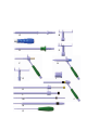
Aesculap Spine
Instructions for use/Technical description
S4 Cervical - Navigated Instruments
Gebrauchsanweisung/Technische Beschreibung
S4 Cervical - Navigierte Instrumente
Mode d’emploi/Description technique
S4 Cervical - Instruments navigués
Instrucciones de manejo/Descripción técnica
S4 Cervical Instrumental de navegación
Istruzioni per l’uso/Descrizione tecnica
S4 Cervical - Strumenti navigati
Instruções de utilização/Descrição técnica
S4 Cervical - Instrumentos de navegação
Gebruiksaanwijzing/Technische beschrijving
S4 Cervical - genavigeerde instrumenten
Brugsanvisning/Teknisk Beskrivelse
S4 Cervical - Navigerede instrumenter
Návod k použití/Technický popis
Navigované nástroje S4 Cervical
A
B
C
D
E
F
H
G
I
K
L
M
N
O
J
Aesculap Spine
S4 Cervical - Navigated Instruments
Intended Use
The S4C Navigation Instruments listed within are intended to assist the
surgeon in locating anatomical structures in either open, minimally
invasive, or percutaneous procedures. Indication and contraindications
are specified in the instruction for use for implants (SOP-AIC-5000169).
Legend
Intended use
Navigated screw tap ∅ 3.5 mm (FW655R)
IGS Tool Star Unit (pre-calibrated) (Brainlab)
(55830-20A)
C Handle (FW165R with ratchet or FW067R without ratchet)
D Navigated screwdriver for polyaxial screw (FW656R)
E IGS Tool Star Unit ML (calibration with ICM4) (Brainlab) (55830-25A)
F Navigated drill guide ∅ 3.5 mm, short (FW654R)
G Aesculap star unit Navigation attachment (FW652R)
H Navigated guide sleeve ∅ 4.0 mm for smooth-shank screws (FW658R)
I
Reduction sleeve ∅ 13 mm for Brainlab Instrument Calibration Matrix
Rev. 4 (FW657R)
J Navigated guide sleeve ∅ 3.5/4.0 mm (FW660R)
K C1/C2 inner sleeve guide ∅ 4 mm (FJ985R)
L C1/C2 inner sleeve guide ∅ 3.5 mm (FW661R)
M C1/C2 drill bit ∅ 2.4 mm (FW662SU)
N C1/C2 screw tap ∅ 3.5 mm (FW663R)
O Cortical punch for navigated drill guide FW654R (FW653R)
A
B
Symbols on product and packages
Symbol
Explanation
Sterilization using irradiation
Not for reuse in intended applications as
defined by the manufacturer
Use by
Caution, general warning symbol
Caution, see documentation supplied with the
product
Date of manufacture
4 Cervical
The
Navigation
Instruments
areisindicated
use in cervical
surgicaland
spinal
The SS4C
System
(S4C System)
used for for
posterior
thoprocedures,
in which
use ofIndications
stereotactic
surgery
may be appropriate,
racic stabilisation
andthe
fusion.
and
contraindications
are specand
to afor
rigid
structure
, suchThe
as instruments
the pelvis or
ifiedwhere
in thereference
instructions
useanatomical
for implants
(TA011796).
a vertebrae can be identified relative to the acquired image (CT, MR, 2D
listed in the captions form part of this system. They are used and/or
for thean
indifluoroscopic image or 3D fluoroscopic image reconstruction)
4
C implantsinclude
in patients.
vidual data
adaptation,
positioning
insertion
of Sprocedures
image
based model
of the and
anatomy.
These
but
For not
safelimited
usage,to follow
instructions
for S4CofSystem
are
spinal fusion
duringfor
theuse
navigation
pedicleInstruments
screws (T1T3).
(TA011984) and Operating Technique (O34202).
The instruments listed in the captions may only be used with the Brainlab
navigation system. For safe handling prior to the operation, read Spine &
Trauma user manual for Brainlab instruments and the corresponding software manual for the Brainlab spine application used.
Combination specifications
Aesculap and Brainlab accept absolutely no responsibility if instruments,
awls or drills other than those named below are used with the corresponding drill guides and guide sleeves.
• Only combine S4C navigated drill guide F with:
– S4C-cortical punch for S4C-drill guide O
– Standard drill bit, ∅ 2.4 mm for ∅ 3.5 mm screws (FW051SU)
• Only combine S4C navigated guide sleeve ∅ 4.0 mm H for smoothshank screws with:
– Smooth-shank screw bone awl (FW085R)
– Smooth-shank screw drill (FW086SU)
– Smooth-shank screw tap (FW087R)
– Polyaxial screwdriver (FW070R)
– Navigated screwdriver for polyaxial screw (FW656R)
– Apfelbaum ball end screwdriver, short (FJ968R)
• Only combine S4C navigated guide sleeve ∅ 3.5/4.0 mm J with:
– approved Apfelbaum C1/C2 obturator (FJ983R)
– Apfelbaum trocar (FJ984R)
– Favored Angle screw drill ∅ 2.9 mm for ∅ 4 mm screws (FW088SU)
– Favored Angle screw tap ∅ 4 mm (FW089R)
– C1/C2 inner sleeve guide ∅ 4 mm K (FJ985R)
– S4C Favored Angle screwdriver (FW069R)
– C1/C2 drill bit ∅ 2.4 mm for ∅ 3.5 mm screws (FW662SU) M
– C1/C2 screw tap ∅ 3.5 mm (FW663R) N
– C1/C2 inner sleeve guide ∅ 3.5 mm (FW661R) L
– Apfelbaum ball end screwdriver (FJ988R)
Note
K-wires generally may not be used with the S4C system.
2
Safe handling and preparation
CAUTION
Federal law restricts this device to sale by or on order of a physician!
WARNING
Risk of injury caused by incorrect operation of the
product!
¾ Attend appropriate product training before
using the product.
¾ For information regarding such training, please
contact your national B. Braun/Aesculap
agency.
¾ Ensure that the product and its accessories are operated and used only
by persons with the requisite training, knowledge, or experience.
¾ Read, follow, and keep safe the instructions for use.
¾ Use the product only in accordance with its intended use, see Intended
use.
¾ Remove the transport packaging and thoroughly clean the new product, either manually or mechanically, prior to its initial sterilization.
¾ Store any new or unused products in a dry, clean, and safe place.
¾ Prior to each use, inspect the product for loose, bent, broken, cracked,
worn, or fractured components.
¾ Do not use the product if it is damaged or defective. Set aside the product if it is damaged.
¾ Replace any damaged components immediately with original spare
parts.
¾ To avoid damage to the working end: Carefully insert the product
through the working channel (e.g. trocar).
∅ S4C1/C2 drill bit 2.4 mm (FW662SU), standard drill ∅ 2.4 mm
(FW051SU), Favored Angle screw drill ∅ 2.9 mm (FW088SU) and
drill ∅ 2.9 mm for smooth-shank screws (FW086SU)
DANGER
¾ Prior to each use, inspect the product for loose, bent, broken, cracked
or fractured components.
¾ Do not use the product if it is damaged or defective. Set aside the product if it is damaged.
¾ Do not use the product after expiry of its use-by date.
Safe operation
WARNING
Risk of injury and/or malfunction!
¾ Always carry out a function check prior to
using the product.
Risk of injury to the patient!
WARNING
WARNING
WARNING
Risk of infection of patients and/or users and
impairment of product functionality due to reuse.
Risk of injury, illness or death due to contamination and/or impaired functionality of the product!
¾ Do not reuse the product.
¾ Handle S4C instruments with the greatest of
care as they are extremely precise and highly
sensitive.
¾ Check accurate calibration of dropped or damaged S4C instruments, or send them to the
Aesculap Technical Service.
Risk of injury to the patient!
¾ Prior to the operation, plan the configuration
of the operating room, the assembly of the
instruments and the alignment of the reference star.
¾ Ensure that the navigation camera has an
unrestricted view on the reflective marker
spheres of the instruments.
Risk of injury to the patient!
¾ Ensure that the instruments used are not bent
or damaged.
¾ Before use, check the precision of the instruments, particularly that of fine instruments.
For this, hold the instrument tip in the pivot
point of the Brainlab Instrument Calibration
Matrix Rev. 4.
Risk of injury to the patient!
The product is gamma-sterilized and ships in sterile packaging.
The product must not be reused.
¾ Ensure that the product and its accessories are operated and used only
by persons with the requisite training, knowledge, or experience.
¾ Read, follow, and keep safe the instructions for use.
¾ Use the product only in accordance with its intended use, see Intended
use.
¾ Do not use products from open or damaged sterile packaging.
WARNING
¾ Use navigated S4C instruments only with
Brainlab disposable reflective marker spheres.
Note
For further information on the correct handling of the marker spheres, see
corresponding Brainlab user manual.
3
Aesculap Spine
S4 Cervical - Navigated Instruments
Preparing holes for S4C screws with navigation
Risk of injury to the patient!
¾ Observe the combination specifications
WARNING
To center punch the screw holes in the cortical layer for the self-tapping
S4C screws ∅ 3.5 mm with navigation, use the S4C navigated drillguide
∅ 3.5 mm F only together with S4C cortical punch for S4C navigated drill
guide O.
To center punch screw holes in the cortical layer without navigation, see
instructions for use S4 Cervical Instruments (TA011984).
WARNING
Risk of damage to the spinal cord, nerve roots,
adjacent intervertebral space or soft tissue when
inserting the cortical punch without drill guide!
¾ Use the cortical punch only with drill guide
FW654R.
¾ Mount the Brainlab reflective marker spheres 4 onto Aesculap star
unit G, see Brainlab user manual.
¾ Retract and hold locking sleeve 1 of the Aesculap star unit G against
the spring pressure in the direction of the arrow.
¾ Push Aesculap star unit G onto adapter 2 of the S4C drill guide F. When
doing so, ensure that the pin of the adapter 3 engages in the recess on
the star unit.
¾ Release locking sleeve 1.
DANGER
Risk of injury from an incorrectly placed hole or a
hole that is too deep!
¾ Do not sharpen the drill, as this would cause
imprecise or incorrect readings on the depth
gauge.
¾ Replace blunt drills with new ones.
The drill is applied with a S4C drill guide and drilled in either manually with
the drill handle (FJ839R) or with a motor system with the Aesculap Intrahandpiece (e.g. GD450R/GD456R).
Risk of damage to the spinal cord, nerve roots,
adjacent intervertebral space or soft tissue
through incorrect drilling!
DANGER
F
4
5
O
6
Fig. 1 Mounting the Aesculap star unit on S4C drill guide FW654R
4
Drilling holes for the S4C screws
Assembling the drill and drill handle (for manual drilling only)
G
1
2
3
¾ Prior to each use, check the instrument with the Brainlab Instrument
Calibration Matrix Rev. 4, see Brainlab user manual.
¾ Before using for the first time and before every 10th use, carry out a
validation of the instrument with the Brainlab Instrument Calibration
Matrix Rev. 4, see Brainlab user manual. Ensure that the cortical
punch O for navigated drill guide is removed.
¾ To ensure the camera has an unrestricted view on the reflective marker
spheres, unscrew knob 6 on the S4C handle of the S4C drill guide F and
turn the Aesculap star unit G to the desired position.
¾ Once the desired position is reached, tighten knob 6 again.
¾ Adjust the center punch depth by turning the depth stop 5 on the S4C
drill guide F. The maximum depth is 6 mm.
¾ Insert S4C cortical punch O into S4C drill guide F.
¾ Check the pre-set center punch depth with a caliper (e.g. AA845R).
¾ To open the cortical bone, press S4C cortical punch to the preset depth
under control with the Brainlab navigation system.
¾ Use only the correct S4C drill guides to drill
holes. Insert drill only with the correct drill
guide.
¾ Before drilling, the pre-set drill length must be
checked with a caliper (e.g. AA845R, Caspar
instrument for anterior cervical fusion).
DANGER
Injury to spinal cord and nerve roots caused by
application of a drill that is too long!
¾ Use the X-ray image to select an appropriate
drill length prior to the operation.
¾ The drill may only be aligned and inserted
under radiographic control and/or with the aid
of a navigation system.
¾ Select a drill of a length equivalent to the
intended drill hole depth.
¾ Insert drill in the drill handle (FJ839R), see Fig. 2.
¾ Retract and hold locking sleeve against the spring pressure in the
direction of the arrow.
¾ Push the drill into the receptacle of the drill handle as far as it will go.
¾ Slightly rotate the drill and release locking sleeve.
The drill engages audibly, see Fig. 2.
To drill the holes for the screws with ∅ 4 mm, use standard drill guide
FW053R without navigation, see instructions for use for S4 Cervical
Instruments (TA011984).
¾ Mount the Brainlab reflective marker spheres 4 onto Aesculap star
unit G, see Brainlab user manual.
¾ Retract and hold locking sleeve 1 of the Aesculap star unit G against
the spring pressure in the direction of the arrow.
¾ Push Aesculap star unit G onto adapter 2 of the S4C drill guide F. When
doing so, ensure that the pin of the adapter 3 engages in the recess on
the star unit.
¾ Release locking sleeve 1.
1
2
3
G
F
4
5
Click
Fig. 2 Assembling the drill
DANGER
Risk of injury and/or damage to the drill if the
drill rotation speed is too high!
¾ Use the lowest drilling speed possible, so that
you can control the drilling depth.
¾ Do not bend the drill during the drilling process.
Drilling holes for S4C screws ∅ 3.5 mm
Risk of injury to the patient!
¾ Observe the combination specifications
WARNING
For controlled drilling of the holes for S4C-screws ∅ 3.5 mm with standard drill ∅ 2.4 mm (FW051SU), the S4C navigated drill guide ∅ 3.5 mm F
(FW654R) must always be used.
Note
The drill ∅ 2.9 mm (FW052SU) may not be used with S4C navigated drill
guide F.
6
Fig. 3 Mounting the Aesculap star unit on S4C drill guide FW654R
¾ Prior to each use, check the instrument with the Brainlab Instrument
Calibration Matrix Rev. 4, see Brainlab user manual.
¾ Before using for the first time and before every 10th use, carry out a
validation of the instrument with the Brainlab Instrument Calibration
Matrix Rev. 4, see Brainlab user manual. Ensure that the drill FW051SU
is removed.
¾ To ensure the camera has an unrestricted view on the reflective marker
spheres, unscrew knob 6 on the handle of the S4C drill guide F and turn
the Aesculap star unit G to the desired position, see Fig. 1.
¾ Once the desired position is reached, tighten knob 6 again.
¾ Adjust the drill depth by turning the depth stop 5 on the S4C drill
guide F.
¾ Insert the drill with mounted handle or Intra-handpiece into S4C drill
guide F.
¾ Before drilling, the pre-set drill length must be checked with a caliper
(e.g. AA845R, Caspar instrument for anterior cervical fusion).
¾ Drill to the pre-set depth under control with the Brainlab navigation
system.
5
Aesculap Spine
S4 Cervical - Navigated Instruments
Tapping (optional)
S4C screws are self-tapping. However, if the bone quality is found to be
hard during the operation, the surgeon can also pre-tap the thread with
the S4C screw tap.
¾ For navigated tapping of the drill holes for screws ∅ 3.5 mm, use S4C
navigated screw tap A.
¾ For tapping the drill holes for screws ∅ 4 mm, use the standard screw
tap without navigation (FW047R), see TA011984.
Risk of tissue injury when using the S4C screw tap
(A) and damage to bone thread!
4C
¾ Prior to using the S screw tap, ensure that
the moveable sleeve of the screw tap retracts
correctly.
DANGER
¾ To tap the thread, hold the IGS Tool Star Unit B at the planned indentations with one hand, and with the other hand screw in S4C handle C
slowly and steadily under control with the Brainlab navigation system,
until the required depth is reached.
¾ Use the scale behind the retractable sleeve of the S4C screw tap to read
the depth during the tapping process, see Fig. 5.
A
Fig. 5 Screw tap with readable thread depth
Positioning S4C screw under navigation and temporarily fixing
it in place
Risk of injury to the patient!
¾ Mount the Brainlab reflective marker spheres 4 onto the IGS Tool Star
Unit B (pre-calibrated), see Brainlab user manual.
¾ Push the IGS Tool Star Unit onto the shaft 7 of the S4C navigated screw
tap A. Ensure that the star unit is securely fitted onto the shaft of the
S4C screw tap.
Note
The star unit can be rotated on the shaft of the S4C screw tap.
¾
¾
¾
¾
Retract and hold locking sleeve 8 against the spring pressure.
Attach S4C handle (FW067R or FW165R) to S4C navigated screw tap A.
Push S4C handle onto the shaft of the S4C navigated screw tap A.
Release locking sleeve 8, see Fig. 4.
Check that the S4C handle is engaged.
B
A
B
4
C
7
9
8
Fig. 4 Mounting the IGS Tool Star Unit and S4C handle onto the S4C
screw tap
WARNING
Risk of injury to the patient!
¾ Before use, ensure that the selected instrument
has been correctly assembled.
¾ Ensure that the arrow on the underside of the
IGS Tool Star Unit (pre-calibrated) is pointing
to the tip of the tool.
¾ Prior to each use, check the instrument with the Brainlab Instrument
Calibration Matrix Rev. 4, see Brainlab user manual.
¾ Before using for the first time and before every 5th use, carry out a validation of the instrument with the Brainlab Instrument Calibration
Matrix Rev. 4, see Brainlab user manual.
6
¾ Use S4C screwdriver only with IGS Tool Star
Unit ML for manual calibration.
¾ If you change screws, perform the calibration
again.
DANGER
¾ To position S4C screws ∅ 3.5 mm and ∅ 4 mm under navigation, use
S4C navigated screwdriver D.
¾ Mount the Brainlab reflective marker spheres 4 onto IGS Tool Star Unit
ML E, see Brainlab user manual.
¾ Push the IGS Tool Star Unit ML E onto the shaft 10 of the S4C screwdriver D. Ensure that the star unit is securely fitted onto the shaft of
the S4C screwdriver.
Note
The star unit can be rotated on the shaft of the S4C screwdriver.
¾
¾
¾
¾
Retract and hold locking sleeve 8 against the spring pressure.
Mount S4C handle (FW067R or FW165R) onto S4C screwdriver D.
Push S4C handle onto the shaft of S4C screwdriver D.
Release locking sleeve 8, see Fig. 6.
Check that the S4C handle is engaged.
E
D
4
C
E
10
8
Fig. 6 Mounting the IGS Tool Star Unit and S4C handle (FW067R or
FW165R) onto the S4C screwdriver
Note
The S4C screwdriver is fitted with a self-retaining function to prevent the
S4C screw from falling off when it is passed to the surgeon.
¾ Retract and hold holding sleeve 12 on the S4C screwdriver D.
¾ Insert the tip of the S4C screwdriver D fully into the hexagon of the
screw 11.
¾ Release holding sleeve 12.
Ensure that the screw 11 is securely in place on the S4C screwdriver D
and that the polyaxiality of the screw 11 is blocked.
E
D
C
11
12
Fig. 7 Picking up the
DANGER
S4C
screw with the S4C screwdriver
Risk of injury to the patient!
¾ Before use, ensure that the selected instrument
has been correctly assembled.
¾ Ensure that the arrow on the underside of the
IGS Tool Star Unit ML is pointing to the tip of
the tool.
¾ Prior to using the instrument with the correctly held screw, perform
manual calibration with the Brainlab Instrument Calibration Matrix
Rev. 4, see Brainlab user manual.
¾ Screw in the screw under control with the Brainlab navigation system.
When doing so, hold IGS Tool Star Unit ML at the planned indentations
with one hand, and turn the S4C handle C to screw in the screw 11
with the other hand.
DANGER
Serious complications for the patient can be
caused by incorrect positioning of instruments or
implants!
¾ Carry out operative steps with radiographic
visualization.
¾ When removing the smooth-shank screw awl
(FW085R) and during the further operating
steps, ensure that the S4C navigated smoothshank screw guide sleeve remains securely
fixed in place.
¾ Ensure that the window on the S4C navigated
smooth-shank screw guide sleeve is closed during the preparation of the screw hole and while
the screw is being inserted, see laser marking
on the inner sleeve.
¾ Take care that no tissue gets caught when
opening and closing the window on the S4C
navigated smooth-shank screw guide sleeve,
after the screw has been put in place.
¾ Mount the Brainlab reflective marker spheres 4 onto the Aesculap star
unit G, see Brainlab user manual.
¾ Retract and hold locking sleeve 1 against the spring pressure in the
direction of the arrow.
¾ Push Aesculap star unit G onto adapter 2. When doing so, ensure that
the recess on the star unit is seated over the pin 3 of the adapter.
¾ Release locking sleeve 1.
1
2
3
G
H
Smooth-shank screw instruments
G
Risk of injury to the patient!
¾ Observe the combination specifications
4
13
WARNING
Instruments for smooth-shank screws are marked with a light-blue ring.
They are used to center punch, drill and tap holes for smooth-shank screws
∅ 4 mm.
14
6
Fig. 8 Mounting the Aesculap star unit on the S4C guide sleeve for
smooth-shank screws.
7
Aesculap Spine
S4 Cervical - Navigated Instruments
DANGER
Risk of injury to the patient!
¾ Slide reduction sleeve into the Brainlab Instrument Calibration Matrix Rev. 4, until you hear
an audible click.
¾ Prior to each use, check the instrument with special reduction sleeve I
with the Brainlab Instrument Calibration Matrix Rev. 4, see Brainlab
user manual.
¾ Before using for the first time and before every 10th use, carry out a
validation of the instrument with reduction sleeve I with the Brainlab
Instrument Calibration Matrix Rev. 4, see Brainlab user manual. Ensure
that all other instruments (awl, drill, screw tap etc.) are removed for
the instrument validation.
I
¾ Insert the smooth-shank screw tap into the inner sleeve and slowly and
steadily screw in until the desired depth. When doing so, read the
thread depth on the screw tap scale.
¾ Remove smooth-shank screw tap from the operating field.
Note
If the S4C screw with S4C screwdriver FW656R is planned to be inserted
under navigation with the guide sleeve H, remove the Aesculap star unit on
the S4C guide sleeve for smooth-shank screws.
Risk of injury to the patient!
DANGER
¾ The navigated S4C screwdriver FW656R or
other screwdrivers are only intended for navigation in the non-navigated S4C guide sleeve
FW658R.
¾ Navigate the S4C screwdriver FW656R, see
positioning S4C screw under navigation and
temporarily fix it in place.
Fig. 9 Reduction sleeve for validation/verification with the Brainlab
Instrument Calibration Matrix Rev. 4
¾ To ensure the camera has an unrestricted view of the reflective marker
spheres, unscrew knob 6 on the S4C handle of the S4C guide sleeve H
and turn the Aesculap star unit G to the desired position, see Fig. 8.
¾ Once the desired position is reached, tighten knob 6 again.
¾ Place S4C guide sleeve H for smooth-shank screws in the operating
field. When doing so, ensure that the window of the guide sleeve is
closed during the preparation and insertion of the screw with the guide
sleeve, see laser marking on the inner sleeve 13.
¾ Center punch the cortical layer of the vertebral body with the smoothshank screw awl (FW085R), see TA011984.
¾ If necessary, insert the awl into the inner sleeve 13 and center punch
the bone as far as the stop-position. The stop-position is indicated with
a marking on the awl.
¾ Remove the awl from the operating field.
¾ Insert the smooth-shank screw drill (FW086SU) 14 with mounted handle (FJ839R) or Intra-handpiece into the inner sleeve 13.
¾ Before drilling, the pre-set drill length must be checked with a caliper
(e.g. AA845R, Caspar instrument for anterior cervical fusion).
¾ Under control with the Brainlab navigationssystem, drill a hole in the
bone until the adjustable stop-position is reached. For further information on drilling, see instructions for use for S4 Cervical Instruments
(TA011984).
¾ Remove the drill from the operating field.
¾ To prepare the drill holes for the screws, tap the thread with the
smooth-shank screw tap (FW087R).
8
DANGER
Risk of injury to the patient through freely rotating screws!
¾ Do not screw in screw so far that the screw
head comes into contact with the S4C guide
sleeve.
Note
Use navigated S4C screwdriver FW656R only with non-navigated S4C guide
sleeve FW658R.
¾ Navigate S4C screwdriver, see Positioning S4C screw under navigation
and temporarily fixing it in place.
¾ Insert the screw through the S4C guide sleeve but do not screw it in
completely (smooth shank must remain free). Remove S4C screwdriver
D from the operating field.
¾ Remove instrument from the screw:
– Turn the blue inner sleeve 13 and open the window on the S4C guide
sleeve.
– Carefully push away S4C guide sleeve H laterally from the screw.
– Remove S4C guide sleeve H from the operating field.
Instruments for Favored Angle screws
Risk of injury to the patient!
¾ Observe the combination specifications
WARNING
Favored Angle instruments are marked with a gold-colored ring.
DANGER
Serious complications for the patient can be
caused by incorrect positioning of instruments or
implants!
¾ Carry out operative steps with radiographic
visualization.
¾ When removing the obturator (FJ983R) and
during the further operating steps, ensure that
the S4C guide sleeve remains securely fixed in
place.
Drilling holes for Favored Angle screws
¾ Mount the Brainlab reflective marker spheres 4 onto Aesculap star
unit G, see Brainlab user manual.
¾ Mount Aesculap star unit G onto S4C navigated guide sleeve ∅ 3.5/
4.0 mm J. When doing so, retract and hold the locking sleeve 1 against
the spring pressure in the direction of the arrow.
¾ Push Aesculap star unit G onto adapter 2 of the S4C guide sleeve J.
When doing so, ensure that the recess is seated over the pin 3 of the
adapter.
¾ Release locking sleeve 1.
J
1
2
3
G
4
15
Note
So as not to lose the entry opening, keep the drill in the drill hole, press the
button 16 on the inner sleeve guide K and push down the guide sleeve until
it reaches the stop on the bone surface. Then remove the drill and inner
sleeve guide K from the S4C guide sleeve J.
J
K
¾ Prior to each use, check the instrument with the Brainlab Instrument
Calibration Matrix Rev. 4, see Brainlab user manual. Ensure that the
inner sleeve guide K is mounted prior to this check.
¾ Before using for the first time and before every 10th use, carry out a
validation of the instrument with the Brainlab Instrument Calibration
Matrix Rev. 4, see Brainlab user manual. Ensure that the inner sleeve
guide K is mounted prior to this validation.
¾ To ensure the camera has an unrestricted view of the reflective marker
spheres, unscrew knob 6 on the S4C handle of the S4C guide sleeve J
and turn the Aesculap star unit G to the desired position, see Fig. 10.
¾ Once the desired position is reached, tighten knob 6 again.
¾ Then remove inner sleeve guide K again from the S4C guide sleeve J.
¾ Slide obturator (FJ983R) into the inner sleeve 15 of the S4C guide
sleeve J.
The obturator engages in the inner sleeve and can still be rotated.
¾ Bring S4C guide sleeve J with mounted obturator into the operating
field through the stab incision and position it in place.
¾ Press the button 16 on the obturator (FJ983R) and withdraw the obturator from the inner sleeve 15.
¾ If necessary, slide Apfelbaum trocar (FJ984R) into the inner sleeve 15
and insert into the bone to center punch the screw entry point.
¾ Remove the trocar from the operating field.
¾ Push inner sleeve guide K onto the inner sleeve 15.
The inner guide sleeve engages on the inner sleeve and can still be
rotated, see Fig. 10.
¾ Insert drill for Favored Angle screws (FW088SU) with mounted handle
(FJ839R) or Intra-handpiece into the inner sleeve guide K.
¾ Drill to the pre-set depth under control with the Brainlab navigation
system. The drill depth can be read on the scale on the inner sleeve
guide K. For further information on drilling, see instructions for use for
S4 Cervical Instruments (TA011984).
16
¾ Press button 16 and remove the inner sleeve guide K from the inner
sleeve 15.
¾ To prepare screw holes, insert the Favored Angle screw tap ∅ 4 mm
(FW089R) into the inner sleeve 15 and tap. The drill depth can be read
on the scale on the screw tap.
¾ Turn the screw tap counterclockwise until it almost exits the bone.
6
Fig. 10
Mounting the Aesculap star unit onto the S4C guide sleeve;
inserting the S4C drill guide
9
Aesculap Spine
S4 Cervical - Navigated Instruments
Note
So as not to lose the entry opening, turn the screw tap counterclockwise
until it almost exits the bone. Then turn the inner sleeve 15 counterclockwise and at the same time push down the S4C guide sleeve J until it reaches
the stop on the bone surface. After that, completely unscrew the Favored
Angle tap ∅ 4 mm (FW089R) from the bone and together with the inner
sleeve 15 remove it from the S4C guide sleeve J.
Inserting the screw
¾ Ensure that the inner sleeve 15 has been removed from the S4C guide
sleeve J by turning it counterclockwise.
¾ Pick up a suitable Favored Angle screw ∅ 4.0 mm with the self-retaining S4C screwdriver (FW069R). When doing so, retract and hold the
holding sleeve 12 against the spring pressure.
Note
The self-retaining function of the instrument prevents the screw from falling off of the S4C screwdriver when it is being passed to the operating surgeon
¾ Press the working end of the S4C screwdriver fully into the hexagon of
the screw 11.
¾ Release the holding sleeve 12.
¾ Screw in the screw under control with the Brainlab navigation system.
¾ Tighten the screw. When doing so, work through the S4C guide sleeve.
¾ Activate the holding sleeve 12 and release the S4C screwdriver from
the screw.
¾ Remove the S4C guide sleeve and S4C screwdriver from the operating
field.
DANGER
Serious complications for the patient can be
caused by incorrect positioning of instruments or
implants!
¾ Carry out operative steps with radiographic
visualization.
¾ When removing the obturator (FJ983R) and
during the further operating steps, ensure that
the guide sleeve remains securely fixed in
place.
¾ Mount the Brainlab reflective marker spheres 4 onto Aesculap star unit
G, see Brainlab user manual.
¾ Mount Aesculap star unit G onto S4C navigated guide sleeve ∅ 3.5/
4.0 mm J. When doing so, retract and hold the securing sleeve 1
against the spring pressure in the direction of the arrow.
¾ Push Aesculap star unit G onto adapter 2 of the S4C guide sleeve J.
When doing so, ensure that the recess is seated over the pin 3 of the
adapter.
¾ Release locking sleeve 1.
1
2
3
J
G
G
15
Standard screw (∅ 3.5 mm) instrumentation with Favored
Angle instruments
J
4
L
16
Risk of injury to the patient!
¾ Observe the combination specifications
WARNING
To insert standard screws ∅ 3.5 mm with the Favored Angle instruments,
instruments L, M and N must also be used. These instruments are marked
with a black ring.
10
6
Mounting the Aesculap star unit onto the S4C guide sleeve;
inserting the S4C drill guide
¾ Prior to each use, check the instrument with the Brainlab Instrument
Calibration Matrix Rev. 4, see Brainlab user manual. Ensure that the
inner sleeve guide L is mounted prior to this check.
Fig. 11
¾ Before using for the first time and before every 10th use, carry out a
validation of the instrument with the Brainlab Instrument Calibration
Matrix Rev. 4, see Brainlab user manual. Ensure that the inner sleeve
guide L is mounted prior to this validation.
¾ To ensure the camera has an unrestricted view of the reflective marker
spheres, unscrew knob 6 on the S4C handle of the navigated S4C guide
sleeve J and turn the Aesculap star unit G to the desired position, see
Fig. 11.
¾ Once the desired position is reached, tighten the knob 6 again.
¾ Then remove inner sleeve guide L again from the guide sleeve J.
¾ Slide obturator (FJ983R) into the inner sleeve 15 of the S4C guide
sleeve J. The obturator engages in the inner sleeve and can still be
rotated.
¾ Bring S4C guide sleeve J with mounted obturator into the operating
field through the stab incision and position it in place.
¾ Press the button 16 on the obturator (FJ983R) and withdraw the obturator from the inner sleeve 15.
¾ If necessary, slide Apfelbaum trocar (FJ984R) into the inner sleeve 15
and insert into the bone to center punch the screw entry point.
¾ Remove the trocar from the operating field.
¾ Push inner sleeve guide L onto the inner sleeve 15. The inner guide
sleeve engages on the inner sleeve and can still be rotated, see Fig. 11.
¾ Insert drill ∅ 2.4 mm M with mounted handle (FJ839R) or Intra-handpiece into the inner sleeve guide L.
¾ Drill to the pre-set depth under control with the Brainlab navigation
system. The drill depth can be read on the scale on the inner sleeve
guide L. For further information on drilling, see instructions for use for
S4 Cervical Instruments (TA011984).
Note
So as not to lose the entry opening, keep the drill in the drill hole, press the
button 16 on the inner sleeve guide L and push down the guide sleeve until
it reaches the stop on the bone surface. Then remove drill and inner sleeve
guide L from the S4C guide sleeve J.
¾ Press button 16 and remove inner sleeve guide L from the inner
sleeve 15.
¾ To prepare screw holes, insert the C1/C2 screw tap ∅ 3.5 mm N into
the inner sleeve 15 and tap. The drill depth can be read on the scale on
the screw tap.
Note
So as not to lose the entry opening, turn the screw tap counterclockwise
until it almost exits the bone. Then turn the inner sleeve 15 counterclockwise and at the same time push down the S4C guide sleeve J until it reaches
the stop on the bone surface. After that, completely unscrew tap N from the
bone and together with the inner sleeve 15 remove it from the S4C guide
sleeve J.
Inserting the screw
¾ Ensure that the inner sleeve 15 has been removed from the S4C guide
sleeve J by turning it counterclockwise.
¾ Pick up a suitable standard screw ∅ 3.5 mm with the self-retaining
S4C screwdriver (FW069R). When doing so, retract and hold the holding sleeve 12 against the spring pressure.
Note
The self-retaining function of the instrument prevents the screw from falling off of the S4C screwdriver when it is being passed to the operating surgeon.
¾ Press the working end of the S4C screwdriver fully into the hexagon of
the screw 11.
¾ Release the holding sleeve 12.
¾ Screw in the screw under control with the Brainlab navigation system.
¾ Tighten the screw. When doing so, work through the S4C guide sleeve.
¾ Activate the holding sleeve 12 and release the S4C screwdriver from
the screw.
¾ Remove the S4C guide sleeve and S4C screwdriver from the operating
field.
11
Aesculap Spine
S4 Cervical - Navigated Instruments
S4C navigated guide sleeve for smooth-shank screws, FW658R
Disassembling
S4C navigated screw tap ∅ 3.5 mm, FW655R
¾ Loosen nut 19 and unscrew from the sleeve 17.
¾ Remove sleeve 17 together with spring 18 in the direction of the
arrow.
¾ Turn inner sleeve 26 to the "remove" position and remove it from the
outer sleeve in the direction of the arrow.
¾ Loosen knob 25 counterclockwise, unscrew and remove it from the
handle by pulling in the direction of the arrow.
26
A
17
Fig. 12
18
H
19
25
Disassembling the S4C screw tap
S4C navigated screwdriver, FW656R
¾ Retract and hold green holding sleeve 22 against the spring pressure.
¾ Unscrew screw sleeve 20 at the working end of the S4C screwdriver
and remove it from the shaft.
¾ Release green holding sleeve 22.
¾ Push the green holding sleeve 22 with the retaining tongues in the
direction of the instrument's working end and remove it from the
screwdriver shaft.
21
20
22
Fig. 15
Disassembling the guide sleeve
S4C navigated guide sleeve ∅ 3.5/4.0 mm, FW660R
¾ Loosen inner sleeve 27 counterclockwise, unscrew and remove it from
the handle by pulling in the direction of the arrow.
¾ Loosen knob 25 counterclockwise, unscrew and remove it from the
handle by pulling in the direction of the arrow.
23
27
J
25
D
Fig. 13
Disassembling the S4C screwdriver
S4C navigated drill guide ∅ 3.5 mm, FW654R
¾ Turn guide sleeve 24 clockwise and remove it. Be aware that it is a lefthanded thread.
¾ Loosen knob 25 counterclockwise, unscrew and remove it from the
handle by pulling in the direction of the arrow.
24
F
Fig. 16
Disassembling the guide sleeve
Assembling
S4C navigated screw tap ∅ 3.5, FW655R
¾ Push guide sleeve 17 together with spring 18 onto the S4C navigated
screw tap A in the direction of the arrow and turn nut 19 clockwise to
tighten it.
A
25
17
Fig. 14
12
Disassembling the S4C drill guide
Fig. 17
18
19
Assembling the S4C navigated screw tap
S4C navigated screwdriver, FW656R
S4C navigated guide sleeve for smooth-shank screws, FW658R
4
CAUTION
The S C screwdriver will not function properly if
the retaining tongues are bent or kinked!
¾ Do not bend or kink the retaining tongues.
¾ Insert inner sleeve 26 into the outer sleeve in the direction of the arrow
in the "remove" position.
¾ Then turn to "closed" position.
¾ Push knob 25 into the handle of the instrument, screw in clockwise
and tighten it.
26
¾ Push green holding sleeve 22 with retaining tongues 21 onto the
screwdriver shaft so that the retaining tongues engage in the
grooves 23 of the screwdriver shaft.
¾ Retract and hold green holding sleeve 22 against the spring pressure.
¾ Screw screw sleeve 20 onto the working end of the S4C screwdriver D
and tighten it.
¾ Release green holding sleeve 22.
21
20
22
23
25
Fig. 20
Assembling the guide sleeve
4
S C navigated guide sleeve ∅ 3.5/4.0 mm, FW660R
D
Fig. 18
H
Assembling the S4C screwdriver
S4C navigated drill guide ∅ 3.5 mm, FW654R
¾ Push inner sleeve 27 into the outer sleeve in the direction of the arrow,
screw in clockwise and tighten it.
¾ Push knob 25 into the handle of the instrument, screw in clockwise
and tighten it.
¾ Screw on guide sleeve 24 counterclockwise. Be aware that it is a lefthanded thread. You will hear and feel the guide sleeve clicking into
position every half turn.
¾ Push knob 25 into the handle of the instrument, screw in clockwise
and tighten it.
J
27
25
24
Fig. 21
F
25
Fig. 19
Assembling the S4C drill guide
Assembling the guide sleeve
Validated reprocessing procedure
Note
National laws, national and international standards and directives, and
product-specific hygiene regulations for reprocessing must be observed.
Note
For patients with Creutzfeldt-Jakob disease (CJD), suspected CJD or possible variants of CJD, observe the relevant national regulations concerning
the reprocessing of products.
Note
Mechanical reprocessing should be favored over manual cleaning as it
gives better and more reliable results.
13
Aesculap Spine
S4 Cervical - Navigated Instruments
Note
It should be noted that successful reprocessing of this medical device can
only be guaranteed following prior validation of the reprocessing method.
The operator/sterile processing technician is responsible for this.
Note
Up-to-date information on reprocessing can be found on the Aesculap
Extranet at www.aesculap-extra.net
Single-use products
DANGER
Risk of infection of patients and/or users and
impairment of product functionality due to reuse.
Risk of injury, illness or death due to contamination and/or impaired functionality of the product!
¾ Do not reprocess the product.
The following products may not be reprocessed.:
• S4C C1/C2 drill bit ∅ 2.4 mm (FW662SU)
• Standard drill ∅ 3.5 mm (FW051SU)
• Favored Angle screw drill (FW088SU)
• Smooth-shank screw drill (FW086SU)
General information
To prevent increased contamination of loaded instrument trays during use,
please ensure that contaminated instruments are collected separately and
not returned to the instrument tray.
Dried or affixed surgical residues can make cleaning more difficult or ineffective and lead to corrosion of stainless steel. Therefore the time interval
between application and processing should not exceed 6 h; also, neither
fixating pre-cleaning temperatures >45 °C nor fixating disinfecting
agents (active ingredient: aldehydes/alcohols) should be used.
Excessive measures of neutralizing agents or basic cleaners may result in
a chemical attack and/or to fading and the laser marking becoming
unreadable visually or by machine for stainless steel.
Residues containing chlorine or chlorides e.g. in surgical residues, medicines, saline solutions and in the service water used for cleaning, disinfection and sterilization will cause corrosion damage (pitting, stress corrosion) and result in the destruction of stainless steel products. These must
be removed by rinsing thoroughly with demineralized water and then drying.
Only process chemicals that have been tested and approved (e.g. VAH/
DGHM or FDA approval or CE mark) and which are compatible with the
product’s materials according to the chemical manufacturers’ recommendations may be used for processing the product. All the chemical manufacturer's application specifications regarding temperature, concentration
and contact time should be strictly observed. Failure to do so can result in
the following problems:
• Optical changes of materials, e.g. fading or discoloration of titanium or
aluminum. For aluminum, the application/process solution only needs
to be of pH >8 to cause visible surface changes.
• Material damage such as corrosion, cracks, fracturing, premature aging
or swelling.
¾ Do not use process chemicals that cause stress cracks or brittleness in
plastics.
¾ Clean the product immediately after use.
Please see www.a-k-i.org for more detailed information on hygienically
safe reprocessing which is protective of materials and retains their value.
¾ Use suitable cleaning/disinfecting agents if the product is put away in
a wet condition. To prevent foam formation and diminished effectiveness of the process chemicals: Prior to mechanical cleaning and disinfection, rinse the product thoroughly with running water.
Preparations at the place of use
¾ Disassemble the product immediately after use, as described in the
respective instructions for use.
¾ Open all valves/faucets.
¾ Rinse surfaces inaccessible to visual inspection, e.g. in products with
hidden gaps or lumens or products with complex geometries, preferably with distilled water, using e.g. a disposable syringe.
¾ Remove any visible surgical residues to the extent possible with a
damp, lint-free cloth.
¾ Transport the dry product in a sealed waste container for cleaning and
disinfection within 6 hours.
Preparation before cleaning
¾ Disassemble the product prior to cleaning, see Disassembling.
Cleaning/disinfection
CAUTION
14
Damage to the product due to inappropriate
cleaning/disinfecting agents and/or excessive
temperatures!
¾ Use the cleaning/disinfectant agent according
to manufacturer instructions.
¾ Observe specifications regarding concentration,
temperature, and exposure time.
¾ Do not exceed the maximum allowable cleaning temperature of 55 °C.
¾ Carry out ultrasound cleaning:
– as an effective mechanical supplement to manual cleaning/disinfection.
– as a pre-cleaning procedure for products with encrusted residues, in
preparation for mechanical cleaning/disinfection.
– as an integrated mechanical support measure for mechanical cleaning/disinfection.
– for additional cleaning of products with residues left after mechanical cleaning/disinfection.
Note
For cleaning and disinfecting the IGS Tool Star Unit (pre-calibrated) and
the IGS Tool Star Unit ML (calibration with ICM4), see Brainlab user manual.
FW652R, FW654R, FW658R, FW660R, FW661R and FJ985R
Danger to the patient!
¾ Only mechanically clean the product.
Mechanical alkaline cleaning and thermal disinfection
Art. no.
Designation
FW653R
Cortical punch for navigated drill guide FW654R O
FW657R
Reduction sleeve ∅ 13 mm for calibration unit I
FW663R
C1/C2 screw tap
∅ 3.5 mm N
Manual pre-cleaning with brush and subsequent mechanical alkaline
cleaning and thermal disinfection
Art. no.
Designation
FW652R
Aesculap star unit navigation attachment G
FW654R
Navigated drill guide ∅ 3.5 mm,
short F
FW655R
Navigated screw tap ∅ 3.5 mm A
FW656R
Navigated screwdriver for polyaxial screw D
FW658R
Navigated guide sleeve ∅ 4.0 mm for smooth-shank
screws H
FW660R
Navigated guide sleeve ∅ 3.5/4.0 mm J
WARNING
Note
Listed below are the reprocessing procedures approved for the individual
system components.
Manual cleaning with immersion disinfection
Manual pre-cleaning with ultrasound and brush, and subsequent
mechanical alkaline cleaning and thermal disinfection
Art. no.
Designation
Art. no.
Designation
FW067R
Handle without ratchet C
FJ985R
C1/C2 inner sleeve guide ∅ 4 mm K
FW165R
Handle with ratchet C
FW661R
C1/C2 inner sleeve guide ∅ 3.5 mm L
FW653R
Cortical punch for navigated drill guide FW654R O
Manual cleaning/disinfection
FW655R
Navigated screw tap
∅ 3.5 mm A
FW656R
Navigated screwdriver for polyaxial screw D
FW657R
Reduction sleeve ∅ 13 mm for calibration unit I
FW663R
C1/C2 screw tap ∅ 3.5 mm N
¾ Keep working ends open for cleaning.
¾ When cleaning instruments with movable hinges, ensure that these are
in an open position and, if applicable, move the joint while cleaning.
¾ After manual cleaning/disinfection, check visible surfaces visually for
residues.
¾ Repeat the cleaning process if necessary.
15
Aesculap Spine
S4 Cervical - Navigated Instruments
Manual cleaning with immersion disinfection
Phase
Step
T
[°C/°F]
t
[min]
Conc.
[%]
Water
quality
Chemical
I
Disinfectant
Cleaning
RT
(cold)
>15
2
D–W
BBraun Stabimed; aldehyde-free, phenol-free
and QUAT-free
II
Intermediate rinse
RT
(cold)
1
-
D–W
-
III
Disinfection
RT
(cold)
15
2
D–W
BBraun Stabimed; aldehyde-free, phenol-free
and QUAT-free
IV
Final rinse
RT
(cold)
1
-
FD-W
-
V
Drying
RT
-
-
-
-
D–W:
FD–W:
RT:
Drinking water
Fully desalinated water (demineralized, low microbiological contamination: drinking water quality at least)
Room temperature
Phase I
Phase III
¾ Fully immerse the product in the cleaning/disinfecting solution for at
least 15 min. Ensure that all accessible surfaces are moistened.
¾ Clean the instrument under running tap water with a suitable cleaning
brush where necessary for as long as it takes to remove all discernible
residues.
¾ For instruments with concealed crevices , lumens or complex geometries, brush non-visible surfaces with a suitable cleaning brush (brush
length: 30/∅: 4.5, e.g. TA011944 and brush length: 20/∅: 2.5, e.g.
TE654202 and brush length: 50/∅: 10, e.g. TA007747) for at least
1 min. or or as long as it takes to remove all discernible residues.
¾ Mobilize non-rigid components, such as set screws, joints, etc. during
cleaning.
¾ Thoroughly rinse these components with the cleaning disinfectant
solution (at least five times), using a disposable syringe (20 ml).
¾ Do not use metal cleaning brushes or other abrasives that would damage the product surfaces and could cause corrosion.
¾ Fully immerse the instrument in the disinfectant solution.
¾ Mobilize non-rigid components, such as set screws, joints, etc. during
disinfection.
¾ Rinse lumens at least 5 times at the beginning of the exposure time,
using a disposable syringe (20 ml) and an appropriate rinsing adapter.
Ensure that all accessible surfaces are moistened.
¾ Drain any remaining water fully.
Phase II
¾ Rinse/flush the instrument thoroughly (all accessible surfaces) under
running water.
¾ Mobilize non-rigid components, such as set screws, joints, etc. during
rinsing.
¾ Drain any remaining water fully.
16
Phase IV
¾ Rinse/flush the instrument thoroughly (all accessible surfaces).
¾ Mobilize non-rigid components, such as set screws, joints, etc. during
final rinse.
¾ Rinse lumens at least 5 times, using a disposable syringe (20 ml) and
an appropriate rinsing adapter.
¾ Drain any remaining water fully.
Phase V
¾ Dry the instrument with a lint-free cloth or medical compressed air.
Mechanical cleaning/disinfecting
Note
The disinfector must be of tested and approved effectiveness (e.g. DGHM or
FDA approval or CE mark).
Note
Ensure Ao >3 000 for the process.The disinfector used for processing must
be serviced and checked at regular intervals.
Note
The disinfector used for processing must be serviced and checked at regular
intervals.
¾ Place the instrument in a tray that is suitable for cleaning (avoiding
rinsing blind spots).
¾ Connect components with lumens and channels directly to the rinsing
port of the injector carriage.
¾ Place instruments in the tray with their hinges open.
Mechanical alkaline cleaning and thermal disinfection
Machine type: Single-chamber cleaning/disinfection device without ultrasound
Phase
Step
T
[°C/°F]
t
[min]
Water
quality
Chemical/Note
I
Prerinse
<25/77
3
D–W
-
II
Cleaning
55/131
10
FD-W
BBRAUN HELIMATIC CLEANER alcaline with tensides,
application solution 0.5%
III
Intermediate rinse
>10/50
1
FD-W
-
IV
Thermal disinfection
90/194
5
FD-W
-
V
Drying
-
-
-
D–W:
FD–W:
According to disinfector program
Drinking water
Fully desalinated water (demineralized, low microbiological contamination: drinking water quality at least)
17
Aesculap Spine
S4 Cervical - Navigated Instruments
Mechanical cleaning/disinfection with manual pre-cleaning
Note
The disinfector must be of tested and approved effectiveness (e.g. DGHM or
FDA approval or CE mark according to DIN EN ISO15883).
Note
Ensure Ao >3 000 for the process.The disinfector used for processing must
be serviced and checked at regular intervals.
Note
The disinfector used for processing must be serviced and checked at regular
intervals.
Manual pre-cleaning with a brush
Phase
Step
T
[°C/°F]
t
[min]
Conc.
[%]
Water
quality
I
Disinfectant
Cleaning
RT
(cold)
>15
2
D–W
BBraun Stabimed; aldehyde-free, phenol-free
and QUAT-free
II
Rinsing
RT
(cold)
1
-
D–W
-
D–W:
RT:
Drinking water
Room temperature
Phase I
¾ Fully immerse the product in the cleaning/disinfecting solution for at
least 15 min. Ensure that all accessible surfaces are moistened.
¾ Clean the product with a suitable cleaning brush until all discernible
residues have been removed.
¾ For instruments with concealed crevices, lumens or complex geometries, brush non-visible surfaces with a suitable cleaning brush (brush
length: 30/∅: 4.5, e.g. TA011944 and brush length: 20/∅: 2.5, e.g.
TE654202 and brush length: 50/∅: 10, e.g. TA007747) for at least
1 min or or as long as it takes to remove all discernible residues.
¾ Mobilize non-rigid components, such as set screws, links, etc. during
cleaning.
¾ After cleaning, thoroughly rinse through these components (at least
five times) with the cleaning solution, using a disposable syringe
(20 ml).
¾ Do not use metal cleaning brushes or other abrasives that would damage the product surfaces and could cause corrosion.
Phase II
¾ Rinse/flush the instrument thoroughly (all accessible surfaces) under
running water.
¾ Mobilize non-rigid components, such as set screws, joints, etc. during
rinsing.
18
Chemical
Manual pre-cleaning with ultrasound and brush
Phase
Step
T
[°C/°F]
t
[min]
Conc.
[%]
Water
quality
Chemical
I
Ultrasonic cleaning
RT
(cold)
>15
2
D–W
BBraun Stabimed; aldehyde-free, phenol-free
and QUAT-free
II
Rinsing
RT
(cold)
1
-
D–W
-
D–W:
RT:
Drinking water
Room temperature
Phase I
¾ Mount jaws protection on the product.
¾ Clean the product in an ultrasonic cleaning bath (frequency 35 kHz) for
at least 15 min. Ensure that all accessible surfaces are immersed and
acoustic shadows are avoided.
¾ Remove jaws protection.
¾ Clean the product with a suitable cleaning brush until all discernible
residues have been removed.
¾ For instruments with concealed crevices, lumens or complex geometries, brush non-visible surfaces with a suitable cleaning brush (brush
length: 30/∅: 4.5, e.g. TA011944 and brush length: 20/∅: 2.5, e.g.
TE654202 and brush length: 50/∅: 3.8, e.g. TA011327) for at least
1 min or or as long as it takes to remove all discernible residues.
¾ Mobilize non-rigid components, such as set screws, links, etc. during
cleaning.
¾ After cleaning, use a 20-ml single-use syringe to rinse thoroughly, for
at least 5 times, these difficult to access parts of the product.
¾ Do not use metal cleaning brushes or other abrasives that would damage the product surfaces and could cause corrosion.
Phase II
¾ Rinse/flush the instrument thoroughly (all accessible surfaces) under
running water.
¾ Mobilize non-rigid components, such as set screws, joints, etc. during
rinsing.
19
Aesculap Spine
S4 Cervical - Navigated Instruments
Mechanical alkaline cleaning and thermal disinfection
Machine type: Single-chamber cleaning/disinfection device without ultrasound
¾ Place the instrument in a tray that is suitable for cleaning (avoiding
rinsing blind spots).
¾ Keep working ends open for cleaning.
¾ Place instruments in the tray with their hinges open.
Phase
Step
T
[°C/°F]
t
[min]
Water
quality
I
Prerinse
<25/77
3
D–W
-
II
Cleaning
55/131
10
FD-W
BBRAUN HELIMATIC CLEANER alcaline
with tensides; application solution 0.5%
III
Intermediate rinse
>10/50
1
FD-W
-
IV
Thermal disinfection
90/194
5
FD-W
-
V
Drying
-
-
-
D–W:
FD–W:
According to disinfector program
Drinking water
Fully desalinated water (demineralized, low microbiological contamination: drinking water quality at least)
Inspection, maintenance and checks
CAUTION
Damage (metal seizure/friction corrosion) to the
product caused by insufficient lubrication!
¾ Prior to function checks, lubricate moving
parts (e.g. joints, pusher components and
threaded rods) with maintenance oil suitable
for the respective sterilization process (e.g. for
steam sterilization: Aesculap STERILIT® I oil
spray JG600 or STERILIT® I drip lubricator
JG5989).
¾ Allow the product to cool down to room temperature.
¾ After each complete cleaning, disinfecting and drying cycle, check that
the instrument is: dry, clean, operational, and free of damage (e.g. broken insulation or corroded, loose, bent, broken, cracked, worn, or fractured components).
¾ Dry the product if it is wet or damp.
¾ Repeat cleaning and disinfection of products that still show impurities
or contamination.
¾ Check that the product functions correctly.
¾ Immediately sort out damaged or inoperative products and have them
sent to Aesculap Technical Service, see Technical Service.
¾ Assemble separable products, see Assembling.
¾ Check for compatibility with associated products.
20
Chemical/Note
Packaging
¾ Appropriately protect products with fine working tips.
¾ Place the product in its holder or on a suitable tray. Ensure that all cutting edges are protected.
¾ Pack trays appropriately for the sterilization process (e.g. in Aesculap
sterile containers).
¾ Ensure that the packaging provides sufficient protection against
recontamination of the product during storage (DIN EN ISO 11607).
Sterilization
Note
The product may only be sterilized when dismantled.
¾ Check to ensure that the sterilizing agent will come into contact with
all external and internal surfaces (e.g. by opening any valves and faucets).
¾ Validated sterilization process
– Disassemble the instrument.
– Steam sterilization through fractionated vacuum process
– Steam sterilizer according to DIN EN 285 and validated according to
DIN EN ISO 17665
– Sterilization using fractionated vacuum process at 134 °C/holding
time 5 min
¾ When sterilizing several instruments at the same time in a steam sterilizer, ensure that the maximum permitted load specified by the manufacturer for the steam sterilizer is not exceeded.
Sterilization for the US market
Service addresses
• Aesculap does not recommend the device sterilized by flash or chemical sterilization.
• Sterilization may be accomplished by steam autoclave in a standard
prevacuum cycle.
To achieve a sterility assurance level of 10-6, Aesculap recommends the
following parameters:
Aesculap Technical Service
Am Aesculap-Platz
78532 Tuttlingen / Germany
Phone: +49 7461 95-1602
Fax:
+49 7461 16-5621
E-Mail: [email protected]
Aesculap Orga Tray/sterile container (perforated bottom)
Minimum cycle parameters*
Sterilization
method
Temp.
Time
Pre-vacuum
270 °F—275 °F 4 min
Minimum drying
time
20 min
*Aesculap has validated the above sterilization cycle and has the data on
file. The validation was accomplished in an Aesculap sterile container
cleared by FDA for the sterilization and storage of these instruments.
Other sterilization cycles may also be suitable, however individuals or hospitals not using the recommended method are advised to validate any
alternative method using appropriate laboratory techniques. Use an FDA
cleared accessory to maintain sterility after processing, such as a wrap,
pouch,etc.
WARNING for the US market
If this device is/was used in a patient with, or suspected of having
Creutzfeldt-Jakob Disease (CJD), the device cannot be reused and
must be destroyed due to the inability to reprocess or sterilize to eliminate the risk of crosscontamination.
Or in the US:
Aesculap Implant Systems, LLC
Attn. Aesculap Technical Services
615 Lambert Pointe Drive
Hazelwood, MO 63042
Aesculap Repair Hotline
Phone: +1 800 214-3392
Fax:
+1 314 895-4420
Other service addresses can be obtained from the address indicated above.
Distributor in the US/Contact in Canada for product
information and complaints
Aesculap Implant Systems, LLC
3773 Corporate Parkway
Center Valley, PA 18034
USA
Storage
¾ Store sterile products in germ-proof packaging, protected from dust, in
a dry, dark, temperature-controlled area.
¾ Store sterile packed single-use products dust-protected in a dry, dark
and temperature-controlled room.
Technical Service
Risk of injury and/or malfunction!
¾ Do not modify the product.
WARNING
¾ For service and repairs, please contact your national B. Braun/
Aesculap agency.
Modifications carried out on medical technical equipment may result in
loss of guarantee/warranty rights and forfeiture of applicable licenses.
21