1
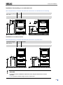
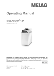
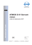
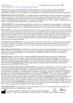
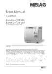
Order confirmation No.: ........................................ MELAtherm®10 What to consider before setup? If customer service is unable to setup the washer disinfector MELAtherm®10 on the date agreed upon as planned, because the requirements for installation on site have not been fulfilled, then this can be quite unnerving, as it usually involves more than costs and hassle in the practice. Therefore, it is important to inspect the on-site installation requirements already available using the checklist and if necessary consult the MELAG customer service. The on-site installation requirements have been inspected by the MELAG authorized customer service / depot technician in the practice / clinic mentioned below: Practice / clinic (name, address) Specialist dealer/MELAG customer service (name, address) ………………………………………………………………......... …………………………………………………..........………… … During set-up by a MELAG customer services employee please check the following points after the check and tick them off, then fax the list to MELAG (Fax +49 (0)30 757 911 99): Space requirements/premises O The width of the door etc. from the practice entrance up to the setup site is at least 60 cm. ® O Sufficient space must be available at the setup site. The setup area of the MELAtherm 10 is 60 cm in width, 60 cm in ® depth and at least 82 cm tall (84 cm with stainless steel cover plate). If a MELAdem 53 is installed, additional space is ® ® required near the MELAtherm 10; dimensions of the ion exchanger cartridge MELAdem 53: (DxH) Ø 24 cm x 57 cm. ® O If the MELAtherm 10 is installed in an L-shaped corner, drawers to the left or right of the device may be blocked and cannot open. O The set-up surface must be able to support a floor load of 2800 N/m² / 4100 N/m² for the top-frame device. Electrical connection Work performed on the electrical system may only be carried out by certified or authorized specialists! O A professional electric connection is to be ensured by the operator. ® ® MELAtherm 10 DTA O O O MELAtherm 10 DTB CEE socket with 380-415 V / 16 A fuse protection A main switch with all-pole disconnection is available Additional FI protection from leakage current 30 mA O O 220-240 V / 50 Hz socket, separate fuse protection with 16 A Additional FI protection from leakage current 30 mA Water connection The cleaning results and the conservation of the instrument value depends greatly on the quality of the tap water. Therefore a optional pre-filter is recommended. O The water drain has to be properly installed under observance of the Technical Manual. The water must drain without obstruction (Careful with pumping equipment installed in the building!). The waste water can be up to 93°C temporary! The pump-off rate amounts to 40 l/min., the amount of effluent up to 30 l/h (in smaller intervals). ▪ ▪ O ▪ ▪ The maximum permissible input water-hardness amounts to 40°dH. Higher levels of hardness necessitates the installation of a water-softening unit. When using a central demineralization system, the maximum permissible conductivity is 5 µS. The device must be connected to the drinking water supply, suitable connections (3/4” external thread) must be available and accessible. The recommended flow pressure amounts for the cold water (CW) and the demineralised water connection (DI) 250 kPa (2.5 bar) - 1000 kPa (10 bar). A water stop, e.g. the water stop of MELAG (Art.-No. 01056) is recommended. Process agents O During setup the process media for commissioning according to the MELAG recommendation (one 5 liter canister of cleaner and neutralizer and at least 1 liter of rinse aid) must be provided. Remarks ………………………………………………………………………………………………………………… The information outlined above has been observed. The installation and commissioning of the device is guaranteed. ………………………………………………………........ Signature of the specialist dealer/MELAG customer service CL_GB_10DT_v3.docx ………………………………………………………........ Signature/stamp of the practice/clinic Rev. 3 – 13/0668 1/1 Approved process agents ® MELAtherm 10 Approved process agents PLEASE NOTE Observe the operating and safety information from the process agent manufacturer. ® If the process agents have a negative effect on the material of the instruments or the MELAtherm 10 despite observation of the manufacturer's information, the manufacturer of the process agents carries liability. The use of process agents not approved by MELAG absolves MELAG of all liability whatsoever for any damage to the device or the instruments IMPORTANT! Process agents from different manufacturers may not be mixed. Any change to another authorized combination may only be performed by trained service partners. The metering concentration must be adapted to local conditions. This is to be performed by the service technician during setup in accordance with the manufacturer's information. Process agent Product – General recom. metering concentration* Cleaner Dr. Weigert neodisher MediClean forte 6-8 ml/l Neutralizer Dr. Weigert neodisher N Dr. Weigert neodisher Z (for particular sensitive instruments) 1.5 ml/l Rinse aid Dr. Weigert neodisher MediKlar 0.3 ml/l Process agent Product – Dental field Cleaner Dr. Weigert neodisher MediClean Dental 6-8 ml/l Neutralizer Dr. Weigert neodisher N Dental Dr. Weigert neodisher Z (for particular sensitive instruments) 1 ml/l 1.5 ml/l Rinse aid Dr. Weigert neodisher MediKlar Dental 0.3 ml/l recom. metering concentration* * When using conventional tap water (hardness range: medium-hard) we recommend the dosage concentrations specified above. These should be adapted to local conditions. The following combinations of process agents were tested for suitability for use with MELAtherm®10, brought into circulation on 1.7.2012: Manufacturer (alphabetically) Cleaner Neutralizer Rinse aid B. Braun Helimatic cleaner alkaline Helimatic neutralizer C Helimatic rinse neutral Bode Dismoclean 21 clean Dismoclean 25 acid Dismoclean 64 neutra-dry Dr. Schumacher Thermoton Cleaner Thermoton N Thermoton clear Dr. Weigert neodisher Mediclean forte neodisher MediClean Dental neodisher Septoclean neodisher N neodisher Z neodisher N dental neodisher Z dental neodisher MediKlar neodisher MediKlar dental neodisher MediKlar special Schülke & Mayr Thermodent alka clean Thermosept RKF forte Thermosept alka clean forte Thermodent neutralizer Thermosept NKP Thermodent clear Thermosept BSK Henry Schein Eurosept Thermo Cleanser Eurosept Thermo Neutralizer Eurosept Thermo Rinse AS_050-10_GB_10DT_v3.docx Rev.: 3 – 13/0859 Page 1 of 1 Setup and installation A B2 B3 B1 C D E F G Under-desk unit Free standing Top-frame device Width A 59.8 cm 59.8 cm 59.8 cm Height B B1 = 81.8 cm B2 = 83.6 cm B3 = 124 cm Depth (with display) C 67.8 cm 67.8 cm 67.8 cm D 8.2 cm 8.2 cm 8.2 cm E 59.1 cm 59.1 cm 59.1 cm F 28.5 cm 28.5 cm 28.5 cm G 96.1 cm 96.1 cm 96.1 cm The space demand is at least 60 cm width, 60 cm depth and 82 cm height. Standing freely in the room using the optional stainless steel cover plates, e.g. next to already-present floor units in your practice. This enables a particularly ergonomic operation and loading of the device. (Without display) If the device is installed in an Lshaped corner, drawers to the left or right of the device may be blocked and cannot open. Serves as storage space, e.g. for up to 6 cans with 5 litres each The stainless steel cover plate can be used additionally Additional space demands when using a water treatment unit: Space for a water treatment unit to be connected to the device water connection could become necessary. If the device is to be installed as a floor unit, this should be placed in an adjacent floor unit. Space ® ® requirements for the MELAdem 53: Ø24 x 57 cm (DxH) and some space above the MELAdem 53 for clear access to the hose connections. 6 Setup and installation Floor space required Place the device on a level and horizontal surface. It is possible to compensate for floor unevenness of max. 10 mm. Observe the required carrying capacity for setting up the individual setup versions (see technical data in the user manual). Install the device on a floor unit In order to install the device on a floor unit, proceed as follows: 1. Unscrew both rear transport rollers and rail (Allen 6 mm). 2. Extend and remove the device feet with a spanner (SW24). 3. Fit the four bolts with a 1 mm and 3 mm thick washer each on all corners of the floor unit with the flat washers and place the device on the floor unit. If the gap between the upper edge of the floor unit and the lower cover of the device is too large, the 1 mm thick washer can be left away: The floor unit also has three transport rollers. To transport the device, the forward transport roller must be extended slightly and the forward feet screwed inwards slightly. After transporting, the third transport roller must be screwed back inwards and both feet extended. To see how to turn device feet in and out, read section Aligning the device. 7 Setup and installation Aligning the device Bring the device into a level position by extending or retracting the front device feet with a spanner (SW24) and then screwing the nut tight with a spanner (SW13). Adjust the central device foot from inside using an Allen key (4 mm), see Removal from the packaging on page 4). Aligning the device with floor unit If the device is installed with a floor unit, the top-frame device can be moved and set up as follows: 1. Remove the drawer of the floor unit to its fullest extent in order to obtain free access to the Allen screws of the rollers and the unit feet. 5x 2. Extend the third fore roller somewhat and retract the two forward feet of the floor unit a little. The top-frame device can now be pushed into its final position. 3. Now extend the two forward feet of the floor unit and retract the middle roller (Allen 5 mm). 4. The rear rollers are also adjusted by extension or retraction. 5. Now fix the position of the Allen screws by countering the nuts. To alter the support rollers on the floor unit drawer proceed as follows: 8 6. Extend the drawer to its fullest extent. 7. Remove the insert mat. 8. Remove the two Allen screw cover caps in the drawer base. 9. The support rollers can be adjusted for height by screwing the Allen screws inwards or outwards (Allen 5 mm). Setup and installation Mains supply ® MELAtherm 10 DTA Electrical connection 1) ® MELAtherm 10 DTB 2) 3N AC 380-415 V , 50 Hz, 3x16A AC 220-240 V, 50 Hz, 1x16A CEE socket with 400 V, separate fuse protection with 16 A, additional RCD switch with 30 mA tripping current separate fuse protection with 16 A, fuse, additional RCD switch with 30 mA tripping current Electric power 9.3 kW 3.3 kW Additional requirements Electrical equipment must correspond with DIN VDE 0100. The mains socket must be freely accessible after installation so that the device can be taken from the electricity supply at any time. A main switch (all-pole) should be fitted on the customer side. This must be marked as the device and easily accessible for the operator. Length of power cable 2m Connection to log ® printer MELAprint 42 An additional socket is required for the mains unit. 2m 1) Observe the maximum voltage range of 360-440 V 2) Observe the maximum voltage range of 207-253 V 9 Setup and installation Water connection Cold water (CW) DI water Waste water Length of water hoses 1.80 m 1.80 m 1.80 m on demand, 3 m extension hose can be ordered (Art. no. 24933) on demand, 3 m extension hose can be ordered (Art. no. 24933) on demand, the present waste water hose can be replaced by a 4 m long one* Connection in practice to the shut-off valve (corner valve) for cold water to a water treatment unit, ® e g. MELAdem 53 to a separate wall drain (DN21) or a present sink drain* (attention: Waste water may reach up to 95 °C for short terms) Min. water pressure 150 kPa (1.5 bar) 150 kPa (1.5 bar) Recommended water pressure 250 kPa (2.5 bar) 250 kPa (2.5 bar) Maximum water pressure (static) 1000 kPa (10 bar) 1000 kPa (10 bar) Connection 3/4“ 3/4“ additional requirements no additional back-flow preventer required (internally secured against return flow into the potable water network according to EN 1717) at MELAdem 53 Always observe all local regulations. Water quality Drinking water according to Drinking Water Ordinance (TrinkW2001) / observe local specifications ® Protected by a safeguard combination with backflow preventer and pipe aerator according to EN 1717 When using a central demineralization system, the maximum permissible conductivity is 5 µS. *alternatively, a lower-noise double chamber siphon of MELAG (Art. no. 26635) can be ordered instead of the present one Also observe the following notes: 10 The cold water inflow hose and the DI water inflow hose and the waste water hose may not be shortened or damaged in any way. The dirt filter in the cold water inflow hose aqua-stop valve may not be removed. Stains on the instruments or the MELAtherm 10 can develop from poor water quality. To avoid the development of stains on the instruments or the washing chamber, we recommend a final rinse with →deionised water (DI water). ® Setup and installation Installation free-standing or as under-desk unit Table 1: Requirements to construction-side waste water connection for an under-desk unit or free-standing Connection height Possible Remarks 0.4 – 1 m Yes --- < 0.4 m Yes Displacement in a curve to at least 0.4 m height 30 cm 20 cm 20 cm EL 10 cm EL 10 cm KW VE AW < 40 cm min. 40 cm AW 60 cm min. 40 cm 60 cm KW VE 30 cm Installation as a cabinet device Table 2: Requirements to construction-side waste water connection for a top-frame device Connection height Possible Remarks Min. 0.74 m Yes --- < 0.74 m Yes Displacement in a curve to at least 0.74 m height AW KW VE 3 cm 60 cm min. 74 cm KW VE EL < 74 cm 10 cm EL 60 cm 20 cm min. 74 cm AW WARNING In case of incorrect installation of the device, there may be interferences in device operation. The specified installation heights must be complied with. 11 Technical Data Technical Data ® MELAtherm 10 DTA Electrical connection 3N AC 380-415V , 50Hz, 3x16A 9.3 kW Device dimensions (HxWxD) MELAtherm 10 DTB 1) 2) AC 220-240 V , 50Hz, 1x16A, 3.3kW Under-desk unit Free standing Top-frame device 81.8 x 59.8 x 67.8 cm 83.6 x 59.8 x 67.8 cm 124 x 59.8 x 67.8 cm 29 x 45.5 x 42.3 cm 29 x 45.5 x 42.3 cm Washing chamber (HxWxD) 29 x 45.5 x 42.3 cm H= max. loading height T= max. loading depth Volume of the washing chamber 84 Litres Weight (empty) 79 kg 85 kg 106 kg Floor loading c. 2,800 N/m² c. 2,800 N/m² c. 4100 N/m² Max. audibility (cleaning) ≤ 62 dBA Waste heat 0.75 kW/h (2.7 MJ/h) Surrounding temperature 15 - 35°C Relative humidity 30 - 60% Max. set-up height 1500 m (it may be necessary to reduce the disinfection temperature depending on the installation height. Consult technical manual) Installation category 2 Air pressure 75 kPa – 106 kPa Connection CW/DI water 3/4“ Effluent connection DN21 Water quality Drinking water according to Drinking Water Ordinance (TrinkW2001)/ observe local specifications Minimum flow pressure 150 kPa (1.5 bar) Recommended flow pressure 250 kPa (2.5 bar) Maximum water pressure 1000 kPa (10 bar) Minimum rinsing pressure 140 mbar Max effluent temperature 93 °C (< 1 min.) Amount of effluent per hour ca. 30 l (in small intervals) Evacuation drain pump max. 40 l/min. (Volume in effluent hose) Length of the intake hose and outlet hose 1.80 m each Length of power cable 2m Degree of soiling Category 2 Degree of protection (following IEC 60529) IP20 CE mark CE 0535 1) Observe the maximum voltage range of 360-440 V 2) Observe the maximum voltage range of 207-253 V 58 ® Model name