1
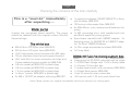
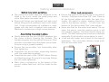
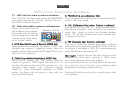
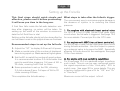
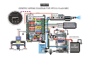
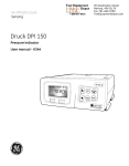
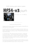
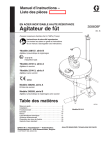
FIDC tracking water injection system
User manual v10w
GETTING TO KNOW THE AQUAMIST HFS-5
Over the last few years, the demand for great engine power output has increased. The cubic inches
option is no longer the norm. Squeezing out 200-300hp per litre is within the reach of the ordinary
folks on the street. The tuning industry has grown to embrace new tuning techniques as well as
readily affordable components to produce powerful and reliable engines.
We at Aquamist have also come to terms with the inevitable, meeting the demands of the market
and offering new systems capable of supporting engine powers output up to 1000+ BHP.
The HFS-5 reads the duty cycle of a fuel injector and delivers water proportional to fuel flow. Water
quantity is metered by a high speed inline valve and flow is monitored by a turbine flow sensor for
clogged jet and severed hose detection. A number of options are available for the user to limit
engine power in the absence of water flow.
We believe the HFS-5 meets all the requirements of a high-end water injection system for achieving fast engine transients and responds with absolute precision. Tracking the fuel delivery is the
most reliable method to deliver your fluid flow under the whole engine operating cycle. Anything
short of this means having to tailor your fuel map to compensate for the irregular fluid quantity ingested by the engine.
Contents:
System Check
Page
4
5
Checking the contents of the box
Getting started on the installation
6
7
8
Installation for long-term reliability
Choosing jet size
Advanced delivery management
9
Generic wiring diagram
Installation
Wiring
Junction board
10
11-14
Junction board function index
Junction board pin-out descriptions
15-16
Gauge function descriptions.
17-18
Setting up the fail-safe
19-21
Customising the system
23
Wiring details Guarantee and Warranty
Gauge
Fail-safe
Advanced
Appendix
Page 4
Checking the contents of the box carefully
This is a “must do” immediately
after unpacking ....
Water pump
Unpack the corrugated sheet carefully. The pump
should be labelled with the original custom Shurflo/
Aquamist logo.
The white box
♦
♦
♦
♦
♦
♦
♦
♦
♦
♦
6M of 6mm OD nylon hose (806-261)
2M of 4mm OD nylon hose (806-266)
15A Fused water pump harness with 40A relay
75mm stainless hose clip and support bracket
HSV with 6/4 mm hose connector and clips and
2-way sealed plug and socket set (806-244)
0.8 mm water jet (806-323) in plastic bag
0.9 mm water jet (806-324) in plastic bag
1.0 mm water jet (806-325) in plastic bag
1x 4mm Y-piece (806-362) in plastic bag
2x M8 x 1/8 NPT jet adapter with plug (806-357
♦ 1x water tank adapter 1/8 BSP (806-270) + 6mm
qck-fit elbow (806-376)
♦ 100 micron inline water filter (806-257)
♦ 4x M5x 40mm, nuts, washers and fasteners for
pump
♦ 1x M6 grounding stud with washed and nuts
and 6mm eyelet for pump ground
♦ 5-port brass manifold with 3/8BSP adapter. 3x
blanking plugs, 1x 3/8 BSP-M to 1/8BSP-F adaptor 2x 6mm 1/8BSP-M elbow.
♦ 1x 22cc surge arrestor/accumulator (806-409)
♦ 1x Pump label
DDS3v10 fluid monitoring system box
♦
♦
♦
♦
♦
♦
♦
Assortment of 22 AWG coloured hook-up wires
1x DDS3 Dash Gauge with 1.5 M x 8-way cable
1x Version 10 Junction box
1x water level switch with connector (806-280c)
1x Digital flow sensor (806-428)
A set of wires for inter-connection
3A fuse link with 1.25 inch quick blow fuse
Note: Please contact your supplier immediately should you discover any missing parts.
Page 5
Getting started on installation
Before installation guidelines
♦ The pump and water tank are designed to be
fitted in the trunk. Install the water pump and
inline filter below the water tank.
♦ Ensure all fittings are tightened and leak proof
before filling up with methanol, test it with water
first. If high concentration of methanol is used,
please vent the tank’s breather hole externally.
Methanol is poisonous at high concentrations.
♦
♦
♦
♦
♦
Assembling the pump in steps
Gently assemble the two 3/8 BSP adapters into
the pump without crossing the threads. The
female one goes into the inlet of the pump. Flow
direction is moulded onto the plastic pump head.
Ensure o-ring is properly seated.
Ensure the accumulator lies horizontally after
final tightening.
Assemble the accumulator supporting bracket
with the metal band supplied.
Assemble the rest of the 1/8 BSP elbow fittings
and blanking plugs. Ensure all o-ring type fittings
are not overly tightened.
Mark (dye is smeared on to the bottom of the
pump’s rubber feet) and drill four holes for the
pump.
Water tank components
♦ Ensure the outlet is facing the rear or the side of
the tank. Drill/bore a burr-free 7/8“ hole. Clear up
all the burred edges and wash the tank thoroughly. No debris or plastic shaving should remain in the delivery system. 1-2 inch from the
bottom of the tank is ideal. Don’t over tighten.
♦ Same size hole for the water level sensor. Do not
place the sensor near the washer pump, it will
not operate properly. The float should swing upwards. The tank venting hole must be re-directed
externally if high alcohol concentration is used.
♦ A tall and slim water tank is ideal for this type of
application. This minimises delivery surge problems at low water level.
150W pump with 125 PSI
Internal bypass valve fitted
Voltage: 12VDC Current: 12A max
Flow rate: Upto 3.0 LPM max
Media: Water and Methanol
ERL reference: 8/125/3D0S
WARNING:
Over 50% Water/Methanol mixture is FLAMMABLE
WATER TANK
806-281
806-270
Page 6
Installation for long-term reliability
The Junction box:
This is the heart of the system and must be installed
in a dry location, preferably sited close to the glove
compartment. Do not install it in the engine compartment, (It has been done !)
Assuming all cables from various locations are
routed to the junction box neatly. Please label the
flow sensor cable to prevent it from wrongly identified with the 4-core cable from the truck area, Once
marked, the cables and wires can be cable tided.
The Flow sensor:
The location of this sensor is most critical to overall
system reliability. It is normally located it in the engine compartment. But there is no reason why it
can’t be spliced into any where between the pump
outlet and jets/nozzles.
The sensor must be installed in a cool area, well
away from the a heat source. Bulkhead/fire wall is
not a good location as most heat is flowing towards
it during motoring. Avoid location near any electromagnetic components such as the ignition coil,
solenoid valves and electronic motors.
It is very important that the hose is cut cleanly with
a razor blade to retain the “roundness”. Side cutter
produces a semi-round hose end, major leak will
result sooner or later. The hose exiting the fitting
must be straight so that the hose is not distorted and
will be badly affected in a hot environment. Again, in
time it will develop a leak.
The most common mistake at this point is cutting
the bundled cables very short to improve tidiness.
Please don’t. Allow a minimum of 2 feet so that the
junction box is accessible when a problem occurs,
Longer cable length will not degrade the system
performance at all.
The Tank level sensor:
Avoid locating the sensor tip close to a washer motor. The motor magnet will affect the sensor to read
properly. The sensor can be installed 3/4 way down
the tank, Preferably at the rear facing wall of the tank.
A 23mm burr-free hole must be used to ensure good
seal. Never over tighten or the seal will split, just tight
enough to prevent leakage, no more.
This is the most important section of the
DDS3 chapter. Please do not skip reading this
part.
The 52mm Dash Gauge:
Location is not too critical as long as it is in view of
the driver. There isn’t too many pitfall on this.
Page 7
Choosing jet size
Pressure vs Flow
This is a general guide only:
- 100% water: run 10-15% water/fuel ratio.
- 50:50 methanol/water, run 15-20% to fuel.
- 100% methanol, run 20-25% to fuel
Choosing the jet by calculation:
First work out the total fuel flow by adding up the
capacity of the fuel injectors. Multiply the result by
the preferred % recommended above.
1.0mm
Pick the nearest jet/jets size to match the flow.
Don’t forget to subtract the boost pressure from
the line pressure of 125psi. For example, if you are
boosting 25psi, you should select the jet flow at
100 psi.
Flow cc/min
0.9mm
0.8mm
0.7mm
Once the jet/jets and flow are determined, insert
the nearest HSV restrictor to regulate the fluid flow
so the delivery will be linear to the duty cycle.
0.6mm
0.5mm
60
70
80
90
100
Pressure (psi)
110
120 125 130
60
46
141
176
211
247
282
317
352
65
48
147
183
220
257
283
330
367
70
50
152
190
228
266
305
343
381
75
52
158
197
236
276
315
355
394
80
54
163
203
244
285
326
366
407
85
55
168
210
252
294
336
378
419
90
57
173
216
259
302
345
388
432
95
58
177
222
266
310
355
399
443
100
60
182
228
273
319
354
410
455
105
61
186
233
280
326
373
420
466
110
63
191
239
286
334
382
429
477
115 120 125 130 PSI
64 66 67 68
195 199 203 208
244 249 254 259
293 299 305 311
342 349 355 365
390 399 407 415
439 449 458 467
488 498 509 519
CC per minute
0.4mm
0.3
0.4
0.5
0.6
0.7
0.8
0.9
1.0
Page 8
Advanced delivery management
The HFS-5 is supplied with a set of high-flow
water jets, sized at 0.8, 0.9 and 1.0mm (see
chart for flow rate). A Y-piece is supplied with
the kit for twin jet applications. There are two
nickel plated brass jet adapters. Three preHSV in-hose restrictors are supplied for duty
cycle/flow matching, should good linearity be
required.
restrictor
HSV clips
HSV
Please note the HSV should not be installed in
areas where there heat and vibration is present. At any point of priming sequence, especially if no fluid is flowing pass it. Do not allow
the HSV to be energised for 30 second at a
time.
The HSV’s wetted parts are designed to work
with “99.9% pure” methanol or ethanol only.
Avoid using alcohol with unknown denaturant.
Always buy alcohol in seal containers or risk
cross-contamination during dispensing.
Applications involving methanol mix beyond 50%:
Great care and attention must be taken to ensure the fluid
tank is capable of handling methanol and is designed for this
type of application. These tanks are normally termed as a
Fuel cell and are available from most reputable racing parts
suppliers. Anti-surge foam should be used for circuit racing.
Follow the maker’s guidelines carefully.
The breather hole must be vented externally with a suitable
hose. All fluid delivery hoses and fittings must be free of all
leaks. Ensure the area is well ventilated and isolated from
the driver’s compartment. Take whatever measures to
avoid any methanol fumes building up in trunk area.
Methanol is highly flammable. The main delivery hose to
the engine bay should be routed underneath the car. Ensure
it is securely clipped and fastened. Avoid kinks, close proximity of moving parts and heat producing components.
Please treat this recommendation seriously. If in doubt, ask
advice from a professional person familiar with this kind of
application. DO NOT take any undue risks. It is recommended that a suitable fire extinguisher is placed within
easy reach of the driver. All electrical connections must be
properly tightened to avoid spark production.
Page 9
GENERIC WIRING DIAGRAM FOR HFS-5 with DDS3v10
Aquamist
200
300
TO HSV
400 ml/m
for
HFS-5
use
only
FLOW
W. INJECTION
WATER LEVEL
SC
WL
WH
2
Made in ng land
E
3
EXT. DUMMY R
OPTIONAL FAIL-SAFE
OUTPUT OPTIONS FOR
INTERFACING TO ECU OR
BOOST CONTROL VALVE
DETAILS CAN BE FOUND
IN THIS USER MANUAL
DDS3v10 JUNCTION BOARD
THIS BOARD CAN ONLY
BE USED ON ONE MODEL
1
4
OK= 5V
+12V
5
6
GND-SW
FAULT
WIPER
CLEAR
7
8
9
10
4-WAY/22AWG
INSTALL
IN E. BAY
INSTALL
CABLE (2M)
IN E. BAY
HSV +
HSV XDR +
XDR MAP SW
BCV +
BCV M-SW-0
M-SW-1
M-SW-2
+12V WFS
0V WFS
806-244
Part No. 806-428
Flow range: 100-450ml/min
Output range: 0.5-4.5VDC
13
Serial No: 22100
Made by ERL Ltd. Sussex England
14
15
16
PWM IN
MPS IN
DIMMING
FUEL INJECTOR MPS (0-5V)
17
18
19
3A FUSE
20
+12v TO DIM
+12V SWITCHED
ENGINE ELECTRICAL
& ELECTRONICS
MANAGEMENT SYSTEM
21
P.RELAY+
P. RELAY+12V IN
+0V IN
22
23
24
25
BLK
GND
DIM-ADJ
MAP SWITCH
RELAY 12v
1A MAXIMUM
87
85
SYS ON
XDR
IDR
806-428
FLOW SENSOR
806-075
100
INSTALL THESE
PARTS IN TRUNK
6M OF 12AWG CABLE
86
40A
RELAY
806-276
39R
30
150W pump with 125 PSI
Internal bypass valve fitted
Voltage: 12VDC Current: 12A max
Flow rate: Upto 3.0 LPM max
Media: Water and Methanol
ERL reference: 8/125/3D0S
WARNING:
Over 50% Water/Methanol mixture is FLAMMABLE
806-409
WATER TANK
IN TRUNK
12V
BATTERY
806-281
806-270
2/10/08 HFS-5 GENERIC.CDR
Page 10
DDS3v10 pinout function directory
This label
defines the
unit is preset
for a unique
WAI system
1
2
3
4
5
6
8
9
+12V WFS
0V WFS
13
14
15
16
PWM IN
MPS IN
DIMMING
17
18
19
20
21
22
23
24
25
HSV +
HSV XDR +
XDR MAP SW
BCV +
BCV M-SW-0
M-SW-1
M-SW-2
1
2
3
4
5
6
7
8
9
10
P.RELAY+
P. RELAY+12V IN
+0V IN
DIM-ADJ
MAP SWITCH
RELAY 12v
1A MAXIMUM
7
DDS3-v10
SYS ON
XDR
IDR
10
16
DUMMY
LOAD
17
18
11
12
13
14
15
1, RJ-45 socket for dash gauge (p.11)
2. Inline flow control valve (p.11)
3. External Anti-CEL dummy load resistor (p.11)
4. MAP switching signal output (p.11)
5. Boost Control valve output (p.11)
6. Voltage free relay outputs (p.11)
7. Led brightness for night driving (p.12)
8. System trigger point adjustment (p.12)
9. LED (green) to monitor IDC (p.12)
10. Selecting external dummy resistor (p.12)
11. 4-core cable to turbine flow sensor (p.13)
12. System trigger signal input (p.13)
13. +12V input to enable led dimming (p.13)
14. Tank level/pump control output (p.13)
15. Main power input (fused), IGN.SW#2 (p.13)
16. Internal Anti-CEL dummy resistor (p.13)
17. LED (red) to show system activation (p.14)
18. User selectable system configuration (p.14)
Page 11
DDS3 junction board pinout descriptions
1. RJ-45 socket for dash gauge:
The DDS3v10 uses a RJ45 connector to link up with
the Dash gauge,
2. Inline flow control valve:
This output can be used to switch an inline solenoid
valve to control flow. Output current is limited to 1
Amp. It is activated by the signal applied to the
PWM (pin17) or MAP (pin18) input.
User can set the triggering point by using the “Tripadj” potentiometer near the bottom of the junction
board.
3. External Anti-CEL dummy load resistor:
A more powerful anti-CEL dummy resistor can be
connected to this output when excessive heat is
produced by the on-board dummy resistor. This
option only applies if pin 9-10 is used for cutting the
PWM signal to a boost control solenoid valve in the
event of failsafe or prolonged “gauge-off period”.
4. MAP switching signal output:
Fail-safe output for map switching usage. This output is about 5V and switch to 0v upon fail-safe
activation. The signal is short circuit proof with a
current limit of 5mA. If an alternative or an inverted
output signal is required. this output pin can be
reprogrammed via a set of soldering pad on the
underside of the circuit board.
Please go to page 15, section C/D for a more detailed description of how this can be done.
5. Fail-safe window output (SW GND)
When flow signal falls inside the fail-safe window,
pin7 will switch to ground immediately. This output
can be used to activate a solenoid valve to increase
boost pressure. This output can also be used to
switch MAP (GND active) on an ECU.
6. Voltage free relay outputs
There are three terminals representing a set of
voltage-free “change-over” contacts from a relay if
anti-CEL -dummy resistor jumper link is un-used.
(p10.6). M-SW1 is the “wiper” or “common” pin.
M-SW1 and M-SW-0 contacts are opened normally
until fail-safe is triggered or gauge is switched off
M-SW1 and M-SW-3 contacts are closed normally
until fail-safe is triggered or gauge is switched off.
Page 12
DDS3 junction board pinout descriptions cont.
7. Led brightness for night driving (p.9)
When pin 19 is linked to the headlamp switch, this
potentiometer enables user to adjust the brightness
level of the gauge leds.
8. System trigger point adjustment (p.9)
This potentiometer sets the triggering point of the
injection system.
In PWM mode, the figure on
the left indicates the IDC trip
point in 6% steps.
Most common onset point is
42%, (12 o’clock).
In MPS mode, the figure on
the left will help to identify
the trip point of a 12 to 72%
Manifold Pressure Sensor. To
translate the signal % to PSI,
please see the table below:
36%
42%
48%
32%
54%
24%
60%
12%
66%
12%
36%
PWM MODE
42%
72%
48%
32%
54%
24%
60%
12%
66%
12%
MPS MODE
72%
.Trip-adj 12 18 24 30 36 42 48 54 60 66 72
2-bar
3-bar
%
-11 -9.3 -7.6 -5.8 -4.1 -2.3 -0.6 1.2 2.9 4.6 5.6 PSI
-9.3 -6.7 -4.1 -1.5 1.7 3.8 6.4 9.0 11.6 14.2 16.8 PSI
MAP sensor conversion table: from % to PSI (shaded = vacuum)
9. LED (green) to monitor IDC
This led will active when a PWM signal is successfully detected on pin17. It should pulse in unison
with the frequency and grows brighter as the duty
cyle % increases. This led should not be lit before
cranking. After the engine has started, it should
pulse in time with engine speed,
If the DDS3 is used as a fail-safe to a third party
WAI system, this led will only pulse when the
PWM pump is activated under normal injection
events.
10. Selecting external dummy resistor
Selecting ext/int dummy resistor. The on-board
Anti-CEL resistor is rated for intermittent usage
during fail-safe activation. In the event of prolong
activation, it will get very warm. To avoid excessive heat build up, it is recommended to use an
external dummy resistor for this purpose,
The external resistor is not supplied with the kit
but it is widely available in electronics store. The
resistor should be 39 ohms, 10W-25W in metal
body.
NOTE: If anti-cel is not necessary, please leave it
on the XDR position or remove the link completely.
Page 13
DDS3 junction board pinout descriptions cont.
11. 4-core cable to turbine flow sensor
Please ensure the stripped wires are twisted
without any loose strands before insertion into
the terminal block connector.
12. System trigger signal input
Choice of two system triggering signal inputs.
Selectable by jumper links (page14.18)
PWM IN (pin17): It reads and translates any
negative going pulses such as fuel injector or
PWM based pump speed controller in to a reference signal to trigger the system and fail-safe
circuitry.
The system is factory set to detect negative
PWM signals. Some pump speed controller uses
a positive PWM switching driver, you need to
re-configure the DDS3 circuit board manually,
(p15.F).
MPS-IN (pin18): 0-5V input signal for triggering
the system instead of PWM. This type of signal
is normally associated with MAP, MAF and TPS
sensors.
The trigger point of the above is set by the Tripadj potentiometer (#8).
13. +12V input to enable led dimming
A 12V signal at this input enables the uses to set the
brightness of gauge (p12.7). It is normally wired to the
head lamp switch so the gauge will automatically dim
during night driving.
14. Tank level/pump control output
These four connections control the delivery pump and
detects water tank fluid level. Control signals are
transmitted via a ~5M of 4-core cable to the trunk area.
15. Main power input (fused), IGN.SW#2
It is important the 12V power is only active at ignition
switch position #2. Ideally, it should be wired to the
same +12V supply to the fuel injectors.
16. Internal Anti-CEL Dummy resistor
If the stock ECU-controlled boost valve is disconnected by the DDS3 during a fail-safe activation, a
CEL (check engine light) is often illuminated.
To prevent this from happening, A dummy resistor is
used to create an artificial load of a boost control
valve.
During this period, the resistor will warm up. If heat
is a concern, use an external resistor, (see page11.3)
Page 14
DDS3 junction board pinout descriptions
17. LED (red) to show system activation
This “SYS ON” red led actives when the PWM/MPS
input signal reaches the “trip adj” setting. The system will commence injection.
F. Set
F. Set
18. User selectable system configuration
Figure on the right shows a
see text -> 1 2 3 4 5
set of default user selectaDIM-ADJ
ble jumper links for setting
up the triggering mode and
manual system test. Read
SYS ON
on for further details
1. MPS (Manifold Pressure Sensor) MODE link:
Selecting this link instead of the default “PWM” link
changes the system’s triggering mode. Now the
system will be looking at the MPS signal (0-5V) at pin
18 to turn the system on.
2. PWM (Pulse Width Modulation) MODE link:
PWM MODE (Factory set). The system looks for
“switch to ground” PWM signal from the pin17 to
turn the fail-safe circuitry and W/A injection on. For
“positive edge trigger” see “Advance setting"
(Page21.F). Upon successful detection of PWM
pulses, the Green led will pulse in time with the
incoming PWM signal.
3. PRK (Parking unused jumper link)
This link space is for parking an un-used jumper link
socket. No other usage.
4. CAL (Calibration Simulation. Default = unlinked)
Linking this pin turns the “SC” potentiometer into a
flow sensor simulator. Fully clockwise for minimum
water flow. Useful to check the fail-safe window
width. “B” led will activate when the simulated flow
is inside the window
5. TST (Manually test. Default= unlinked)
This link is useful for testing the system without
driving the car at full boost and RPM. When this link
is shorted, it simulates a 100% IDC signal appearing
at the PWM input terminal (pin17).
Warning!!! Linking this pin will start the pump and
energise the lnline valve, resulting in 100% maximum fluid delivery to the water jet/jets.
Do not activate this link for more than 5-10 seconds
at a time for risk of burning up a solenoid valve
designed for pulsing purpose use only.
Remove this link as soon as the manual system test
is completed.
Page 15
DDS3v10 Dash Gauge Functions
1
6
7
2
3
8
4
9
5
10
1. 8-element Bargraph Display (80-1800ml/min)
Each segment is equivalent to a percentage of the total
flow of the sensor scaled by the SC potentiometer.
2. “S” indicates the presence of sensor.
The letter “S” (sensor) must be lit after power up and
stay on to show the sensor is functioning correctly.
3. Water injection system ON led
This led comes on the when the system is switched on
and in readiness to inject. .
4. Water Level led (yellow)
(This LED has three functions)
a. During “power on delay” period:
This LED will activate for approximate for 10
seconds during the system-on delay (v10) before the main system turns on.
b. During normal operation period:
- This LED is on during the safe-fail activation
- Water level low (intermittent flashes)
c. Led lit after the gauge is switched off:
- If the water level sensor is activated for over
20 seconds.
- Fail-safe output is in the active state (10.6).
5. SC (Sensor Calibration)
20-stepped potentiometer allow user to scale
the flow sensor to give an ideal visual indication
of a given flow rate. Ideally set the led to display 5-6 bars at full flow.
6. Backlit flow legend
Legend displays % of full scale of 8-bars
7. “B” Boost Enabled led
When the flow falls inside the fail-safe window
after system trigger, this “B” led will activated.
Useful indicator of the WL and WH setting.
Page 16
DDS3v10 Dash Gauge Functions cont.
8. Water injection enable button
Due to extra power level achieved under WI, user
may want to reduce the power to the wheels in less
than ideal driving conditions. Disabling the WI will
reduce boost to wastegate bleed valve setting (if
fitted) as well as switching to a less aggressive MAP
on custom engine management.
9. Over-range setting potentiometer (WH)
It is just as important to monitor over-range conditions as well as under-range flow conditions. If a leak
develops close to the water jet and starves the
engine of the water, the user must know this condition. A 20-stepped potentiometer allows accurate
and repeatable adjustment range.
10. Under-range setting potentiometer (WL)
This setting can indicate partial blockage and trapped
air inside a delivery hose. Again 20-stepped potentiometer is employed. Each click represents a fixed
portion of the window
width of 8-bars.
failsafe window width
coverage (20-clicks)
WL covers the lower 4
bars and the WH covers the upper 4 bars.
Figure on the right illustrates the span of
the coverage. Setting
is very simple once SC
WL
WH
is calibrated.
NOTE:
In order to make the fail-safe adjustment easier, it is
recommended to set the bargraph to display 5-6
bars at maximum flow. This way, the fail-safe window can span from the centre outwards.
If the WL and WH is set at 12 O’clock, the fail-safe
window is approximately spanned between 2-7bars.
A good starting point.
Minor trimming for the WL is necessary if the water
injection trigger point is set to commence earlier.
The v10 gauge will display the activation of the
“fail-safe” with two leds:
Further useful hints:
“B” led (right of the bargraph) will active if the flow
is inside the fail-safe window during injection period.
The yellow led (water level) will activate if the flow
is outside the fail-safe window during injection.
As soon as the “fail-safe ” is tripped, there will be a
4 second reset period before it resets. If the fail-safe
drops boost, expect 4 seconds of low boost. The
same will apply for fail-safe-induced map switch.
When gauge is off, expect low boost and safe map
unless the board is re- configured. (page21.B).
Page 17
Powering up the system.
Powering up the system for the first
time
The system can be activated manually for
priming and leak checks. An external water
jet can be used temporarily check the
spray and bargraph display. It is not necessary to set up the fail-safe at this point.
g. Remove the spare jumper link (prk) on the 5-way programming link to the “TST” link. This will active the pump, the HSV
and the red led (SYS ON). If all is well, unlink after a few
seconds.
Please follow the steps below:
(assuming the system is in PWM mode)
I. Set the gauge and junction board as follows (if necessary):
- SC (sendor calibration) is set to 12 o’clock. (gauge)
- WL (window low) is set to fully counter clockwise
- WH (window high) is set to fully clockwise.
- MPS, CAL & TST on the J. Board are unlinked
- Trip-adj is set to ~ 9 o’clock. (24% IDC)
a. Put the ignition switch to position #1
(ACC). No activity should be observed on
the gauge or junction board. If not, check
wiring.
b. Process to ignition switch position #2
(pre-cranking).
c. The yellow led on the gauge should light
up immediately.
d. Within 10 seconds, the gauge will power
up. No other activity should be observed.
e. Start the engine and let it idle.
f. Check the green led (INJ-IDC) on the
Junction board is pulsing in time when
throttle is applied.
h.This is a good time to check the installation for leaks. Never
over-tighten the fittings to cure leaks.
J. The system is ready for a test drive. Ensure the water jet
is clipped on the windscreen.
K. Upon a successful test run, spray pattern is uniform,
splutter free and activation is predictable. As engine load
increases, the spray should progressively become fuller. The
bargraph on the gauge should change with load.
What next...
The system is now ready. The correct water jet can be
connected to spray internally, reset the trip point to the
preferred value. Allow time for the system to settle down
before proceeding to the next stage of the setting up the
Page 18
Setting up the Failsafe
This final stage should quick simple and
effective, please read it before proceeding.
It will save you time in the long run.
If fluid flow falls inside the fail-safe detection window after triggering, no action will be taken. So
setting up the width of the window to accommodate the full fluid flow is vital.
Setting up the fail-safe should only be done after the
car has been tuned or the jet/jets sizes are finalised.
Recommended steps to set up the fail-safe
1. Adjust the “SC” to display 5-6 bars at full power.
2. Make a mental note of the number of displayed
bars during spool up. Made easier at higher gears.
3. Set the WL to match the number of spool-up bars.
It is recommended to allow 2-3 clicks below that
point to avoid false triggering. Full span of WL is
20 clicks, covering from 0 bar to 4 bars.
What steps to take after the failsafe trigger
The commonest way to minimise engine damage in
the absence of injector is to reducing the boost
pressure.
1. For engines with electronic boost control valve:
Pin 9/10 is a set of relay contact that goes open
circuit when the fail-safe is triggered. See page 10.6
for more details. Connect pin 9 to the ECU side.
2. For engines with MBC (manual boost controller):
Pin 8/9 is a set of relay contact that goes close circuit
during fail-safe activation. Use this output to powerup a solenoid valve to by-pass the MBC. Essentially
allowing full turbo boost to the wastegate. See page
19 for more details.
4. Same procedure to set up the WH, allowing
2-3 clicks above 6 bars. Full span of WH is 20
clicks covering 4-8 bars.
3. For engine with map switching capabilities:
Pin 5 (see page 10.4) is a dedicate output to perform
such a task. This pin can be user configured match
the signal requirement of the “third party” ECU to
switch map. See page 20 for more details. This pin
is factory configured to give a 5V for “OK” and “0v”
is “flow fault”
This completes the fail-safe setup ...
Maximum current of this output is 5mA.
Page 19
Fail-safe wiring for MBC
Upon detection of water flow fault, the HFS-1 can
reduce the boost pressure of a MBC to wastegate
setting with a 2-way Low Current Solenoid valve (not
supplied) - A typical supplier is MAC valve (36A-AAAJDBA-1BA - www.macvalves.com) or Clippard valve
(ECO-3-12-L-M5- www.Cippard.com).
Figure below shows two common type of MBC (manual boost controller) used on most turbo cars.
Type 1: pressure from the turbo to the wastegate is
vented to the atmosphere via a restrictor and a vent.
Boost increase is proportional to the amount vented.
12V IGN
5
NORMALLY
CLOSED
VALVE
6
7
8
LOW
POWER
RESTRICTOR
VENT
9
10
MAP SW
BCV +
BCV M-SW-0
M-SW-1
M-SW-2
Type 2: Boost increase is proportional to the
spring pressure of the MBC.
When the solenoid valve is energised, pressure
from the turbo is diverted to the wastegate directly. When MBC is by-passed, the boost pressure will drop down to wastegate setting.
It is important to use a solenoid valve with a low
power coil winding to avoid over heating during
the by-pass mode. A typical coil power between
3- 6W is acceptable when installed in a cool place.
NORMALLY
CLOSED
VALVE
12V IGN
5
6
7
8
LOW
POWER
9
10
DIM-ADJ
MAP SW
BCV +
BCV M-SW-0
M-SW-1
M-SW-2
DIM-ADJ
MAP SWITCH
RELAY 12v
1A MAXIMUM
MAP SWITCH
RELAY 12v
1A MAXIMUM
XDR
IDR
SET TO XDR
39R
XDR
IDR
SET TO XDR
39R
Page 20
Advance system configuration (solder link)
(Links are factory preset - no need to alter the setting unless customising)
+
+
A B C D E F G
Page 21
Advanced system configuration (solder link)
The DDS3v10 is pre-configured at the factory for a
specific application. When in doubt, please check the
round label on the lid of the box or the small label on
the RJ45 socket at the top right of the junction
board. (factory default: “for Universal fail-safe use”)
switched off at the gauge, only if you are using pin
9/10 to reduce boost to wastegate setting after
fail-safe activation,.
If the user wishes to change the original setting, this
is the section to explain it all. You will require a small
tipped soldering iron and a small pointed tool.
C/D: MSW - Map Switch polarity (default= D-linked)
The factory default output is preset to give a 0V
output upon a fail-safe activation. Otherwise the
output will stay at ~8V.
As seen from the PCB figure on the left. All the user
configurable links are marked with alphabetised
circles.
To invert this output to give out a +8v signal upon a
fail-safe activation, un-solder the pad D(-) and solder
link pad C(+) to the long soldering pad.
Some pads are pre-linked from factory. If you need
to change those, pick off the thin track (pointed tool)
and solder link the alternative solder pads.
E: CMP Clamping MSW signal (default=clamped)
Solder linking this pin will clamp the above MSW
signal down to 4.7V, suitable for most digital devices. It is factory linked to give 4.7V.
A: WLS - Water Level Sensor (default=linked)
Pick off the thin circuit track if you do not wish the
tank level sensor to disable the system after 10-20
seconds of low level reading. (not recommended),
B: DHB - Disable High Boost (default=linked)
Pick off the thin circuit track if you want to retain high
boost or “Aggressive MAP” after the system is
F: PWM MODE polarity (default=negative switched)
To change the PWM detection polarity to positive,
pick off the thin track and solder-link the “+” pad to
the long pad. This mode is rarely used except the
DDS3 is used for monitoring WAI system using a
positive PWM signal to control the water pump
speed. (For example, Snow and Devilsown system)
Page 22
GENERIC WIRING DIAGRAM FOR HFS-5v10 with MBC
Aquamist
200
300
TO HSV
400ml/m
FLOW
W. INJECTION
WATER LEVEL
SC
WL
for
HFS-5
use
only
WH
DDS3v10 JUNCTION BOARD
THIS BOARD CAN ONLY
BE USED ON ONE MODEL
1
2
M ade in ng la n d
E
3
4
5
6
+12V IGN
7
8
9
10
4-WAY/22AWG
INSTALL
IN E. BAY
INSTALL
CABLE (2M)
IN E. BAY
HSV +
HSV XDR +
XDR MAP SW
BCV +
BCV M-SW-0
M-SW-1
M-SW-2
+12V WFS
0V WFS
Serial No: 22100
Made by ERL Ltd. Sussex England
14
15
16
PWM IN
MPS IN
DIMMING
17
FUEL INJECTOR -
18
MPS (0-5V)
19
3A FUSE
20
MAP SWITCH
RELAY 12v
1A MAXIMUM
LOW
POWER
+12v TO DIM
+12V SWITCHED
ENGINE ELECTRICAL
& ELECTRONICS
MANAGEMENT SYSTEM
21
P.RELAY+
P. RELAY+12V IN
+0V IN
BLK
22
23
24
25
GND
87
85
SYS ON
XDR
IDR
Part No. 806-428
Flow range: 100-1200ml/min
Output range: 0.5-4.5VDC
13
DIM-ADJ
NORMALLY
CLOSED
VALVE
FLOW SENSOR
806-244
806-075
100
INSTALL THESE
PARTS IN TRUNK
6M OF 12AWG CABLE
86
40A
RELAY
806-276
39R
SET TO XDR
30
150W pump with 125 PSI
Internal bypass valve fitted
Voltage: 12VDC Current: 12A max
Flow rate: Upto 3.0 LPM max
Media: Water and Methanol
ERL reference: 8/125/3D0S
WARNING:
Over 50% Water/Methanol mixture is FLAMMABLE
806-409
WATER TANK
IN TRUNK
12V
BATTERY
806-281
806-270
2/10/08 HFS-5 GENERIC.CDR
Page 23
Appendix
In Car Dash Gauge (8-core cable)
Pin
Colour Size
Description
1
24awg +12V power supply to gauge
2
24awg Flow Sensor output voltage
3
24awg 0V power supply to gauge
4
24awg Internal communication signal
5
24awg Float Sensor from water tank
6
24awg Flow Sensor calibration output voltage
7
24awg Night driving dimming connection
8
24awg Wastegate bleed valve option (SW-)
@12V max.
Flow Sensor (4-core cable)
Pin
Colour Size
Description
1
Red
24awg +12V power supply of Flow Sensor
2
Blue
24awg 0V power supply of Flow Sensor
3
Yellow 24awg Flow Sensor output voltage
4
Green 24awg Flow Sensor calibration input voltage
Electrical parameter
250mAmax@12v
0-5 VDC @10mA
250mAmax@12v
Ground active
5-0 VDC @1mA
+12V active
1A
Electrical parameter
30mA @ 12v
0V Ground
0-5VDC@10mA
5-0VDC@1mA
DDS3 Junction Box (25-ways - Pin 1= top left corner. Pin 25 bottom right corner)
Pin
Colour Size
Description
Electrical parameter
RJ45
------ 8-core Same as Dash Gauge Above
-----1
Red
22awg +12V power supply to Solenoid valve
+12V, 1A fused
2
Brown 22awg Switching to ground for Solenoid Valve
1A maximum
3
D.Grey 22awg Extending Dummy resistor (+12V side)
1A maximum
4
D,Grey 22awg Extending Dummy resistor (EMS)
1A maximum
5
Orange 22awg Programmable Map switch signal
5mA signal
6
Red
22awg Boost control valve +12V supply
1A max
7
Brown 22awg Boost control valve switch to ground
600mA max
8
Black 22awg Normally closed relay contact (fail-safe)
1A max
9
Grey 22awg Wiper/common relay contact
1A max
10
White 22awg Normally opened relay contact
1A max
11-14 ------ 4-core See 4-core cable description above
-----15
Green 22awg FIDC detect or MAP sensor
Wave input
16
Blue
22awg MAP sensor or 0-5v based sensor
0 to 5V input
17
Pink
22awg Night driving dimming connection
+12V active
18
Yellow 22awg To ground when tank is empty
0.25A maximum
19
Green 22awg Common ground
0.25A maximum
20
Red
22awg Priming pump +12V supply (0.5A FUSED) 0.5A maximum
21
Blue
22awg Priming pump ground switch (active)
1A maximum
22
Red
20awg +12V switched power supply for all
3A maximum
23
Black 20awg 0V ground supply for all
3A maximum
GUARANTEE
ERL guarantees, at our option, to replace faulty goods supplied or repair the same, subject to the claim made in writing
to us within 12 months after the sale by us, or for such other
period as may be indicated by us for specific products in lieu
of any warranty or condition implied by law as to the quality
or fitness for any particular purpose of the goods.
Any claim against us must be made to us in writing within
the period of 12 months after the sale by us , or our agents,
or our distributors of goods in question (or such other period
as may be indicated by us) and any goods to which the claim
relates must be returned to us within that period suitably
packaged and cleaned and, with any particular instructions
which we may have notified to you at the time of supply.
Original invoice, the nature of any claimed defect must accompany the goods in question prior to despatch to us.
If these requirements are not complied with our Guarantee
shall not apply and we shall be discharged from all liability
arising from the supply of defective goods.
LIABILITY
We shall not be under any liability whether in contract, or
tort or otherwise and whether or not resulting from our negligence or that of our employees, in respect of defects in
goods supplied or for any damage or loss resulting from
such defects.
We shall not be under any liability for damage, loss of expense resulting from failures to give advice or information
or giving the incorrect advice or information whether or not
due to our negligence or that of our employees.
In no event shall any breach of contract on our part or tort
(including negligence) or failure of any time on our part that
of our employee give rise to liability for loss of revenue or
consequential loss or damages arising from any cause whatsoever.
Note: ERL reserves the right to make changes to our products without notice in order to improve design performance
and reliability.
ERL ltd
Iroko House
Bolney Ave
Peacehaven
East Sussex
BN10 8HF
England