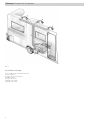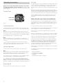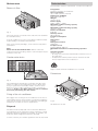
1
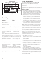
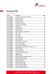
Climaster
Comfort Air Conditioner
Operating instructions
Installation instructions
To be kept in the vehicle!
Page 3
Page 7
Climaster Comfort Air Conditioner
Fig. 1
Installation example
1
2
3
4
5
6
7
2
Air conditioning unit Truma Climaster
Control panel
Indoor air return with filter
Cold air ducts
Indoor air outlets
Outdoor air intake
Outdoor air outlet
Table of contents
Symbols used
Symbols used ........................................................................ 3
Safety instructions ............................................................ 3
The device must only be installed and repaired by an
expert.
Operating instructions
Symbol indicates a possible hazard.
Control Panel .........................................................................
Cooling Operation .................................................................
Heating Operation .................................................................
Switching Off ........................................................................
De-Icing .................................................................................
Notes for the use of the air-conditioner ........................
Maintenance .......................................................................
Return air filter .......................................................................
Condensation drain ...............................................................
Fixing of the air conditioner ..................................................
Disposal ...............................................................................
Technical data .....................................................................
Fault finding ........................................................................
Truma warranty policy .....................................................
4
4
4
4
4
4
5
5
5
5
5
5
6
6
Note containing information and tips.
Safety instructions
Repairs may only be carried out by properly
qualified professionals!
This device may be used by children aged 8 years or above
and by persons with reduced physical, sensory or mental
capabilities or lack of experience and/or knowledge, provided
that they are being supervised or have been given instruction
with regard to the safe use of the device and have understood the potential risks. Children must not use the device as
a plaything. Cleaning and user maintenance must always be
carried out by an expert.
Installation instructions
Data Label .............................................................................
Regulations ...........................................................................
Air conditioner kit ..................................................................
Choice of location ..............................................................
Template ..............................................................................
Inside the caravan ..............................................................
Outside the caravan ...........................................................
Fitting the air conditioning unit .......................................
Installation of the control panel ......................................
Indoor air outflow and return ..........................................
Indoor air outflow ..................................................................
Indoor air return ....................................................................
Electrical connection 230 V / 240 V ...............................
Function check ...................................................................
7
7
7
7
7
7
7
8
9
9
9
9
9
9
To avoid damage during transport, the unit must only be
dispatched after discussion with the Truma Service department (see rear page).
Any work involving connection or interconnecting wiring must
be conducted by a licensed electrician.
The voltage must be disconnected at all poles before the
housing is opened.
The unit fuse, 240 V, 3.15 A (IEC 127) is located on the
electronic control board in the device, and may only be
replaced by a fuse of the same design.
Unit fuses and connection leads may only be replaced by
a licensed electrician.
Any alteration to the unit, or the use of spare parts and
functionally-important accessories which are not original
Truma components, or failure to respect the Installation and
Operating Instructions, will lead to the cancellation of the
guarantee and to the exclusion of claims for liability.
The cooling circuit contains the refrigerant R 407C, and may
only be opened by a properly qualified person.
The indoor air outflow and the return air intake must not on
any account be obstructed. Please bear this in mind in order
to ensure the trouble-free operation of the unit.
The apertures on the side of the vehicle must be kept free of
dirt and snow slush.
In order to avoid damage to the compressor, when the unit is
in operation during transit (for example, with the generator or
voltage transformer working), do not attempt uphill or downhill gradients of more than 5°.
Do not allow the unit to run for extended periods in a tilted
position, since the condensation water which forms may not
be able to run off, and in the worst scenario might penetrate
into the vehicle.
Before switching on, it is essential to make sure that the fuse
system for the power supply at the camp site is sufficient for
950 W (240 V – at least 4.2 A).
The power supply cable for the caravan (minimum crosssection 3 x 2.5 mm²) must be unwound completely from the
cable drum.
3
De-Icing
Operating instructions
Always observe the Operating Instructions and “Important Operating Notes” prior to starting! The vehicle owner
is responsible for ensuring that the unit can be operated in the
proper manner.
The de-icing cycle is associated with the heating mode. It will
set into operation automatically if one of the sensors detects
frost on any of the heat exchangers. The build up of frost
would otherwise impair the cooling or heating capacity of the
unit.
When the de-icing cycle begins the compressor and indoor
fan will stop and after approximately 10 seconds the reversing
valve will be switched on. 30 seconds later the compressor
will re-start. The indoor does not run during the de-icing cycle.
Control Panel
d
yellow light
a
green light
b
c
Fig. 2
The air conditioner will run in this mode until the frost has
been removed and then will automatically resume normal
operation.
Notes for the use of the air-conditioner
The Truma Climaster is recommended for pop-top caravans
and caravans up to 4.8 m overall length, but requires that all
walls and ceilings are insulated with a minimum thickness of
25 mm.
Cooling Operation
As far as possible, park your vehicle in the shade.
1. Turn selector on the control panel to the “b” position for
cooling at low fan speed or “c” for cooling at high fan speed.
Darkening the interior with window blinds and / or a roof awning will reduce the penetration of radiant heat.
Note
The indoor fan starts immediately and the green light is displayed. The compressor starts approximately 30 seconds later.
Clean the roof of the vehicle regularly (dirty roofs heat up
more readily).
2. Set thermostat to a temperature for your individual requirements (wide blue bar – is maximum cooling).
Note
If the room temperature is below 20 °C, the compressor
will not operate and the yellow light in the control panel will
come on.
Before operating the device, ventilate your vehicle thoroughly,
in order to allow the hot air which builds up inside to escape.
Take care when putting up awnings or similar that there are
sufficient openings for the outdoor air to be discharged.
Once the set temperature on the control has been
reached, the green light will go out and the compressor
will switch off. The indoor fan continues to run.
To create a healthy environment on the inside of the vehicle,
the difference between the inside and outside temperatures
should not be selected as too great. During operation the
indoor air will be purified and dried. Due to the drying of
the moist, humid air, a pleasant environment will be created
inside even with slight temperature differences.
Heating Operation
Keep the doors and windows closed while the cooling system
is in operation.
1. Turn selector on the control panel to the “d” position.
Note
After switching on; the green light is displayed, after approximately 30 seconds the compressor starts and after further
30 seconds the indoor fan starts in low speed only.
2. Set thermostat to a temperature for your individual requirements (wide red bar – is maximum heating power).
Heating is not possible at an outside temperature of
less than 4 °C, as the heating power drops significantly.
Between 4 °C and 7 °C the device briefly switches to thawing
processes. Heating is possible without restrictions above 7 °C.
Switching Off
Turn selector on the control panel to the “a” position.
4
The capacity of the air conditioner to adequately cool or heat
is dependant on:
–
–
–
–
–
Size of the caravan
Insulation of the caravan
Size and type of windows
Shading
Ventilation from indoor to outdoor
Maintenance
Technical data
Determined on the basis of EN 14511 or Truma test conditions
Return air filter
Fig. 3
The return air filter is located on the side of the unit and must
be cleaned monthly.
If the air conditioner is in use in very dusty conditions and at
high humidity, it should be cleaned weekly.
Take out the filter by bending it, clean in warm soapy water
and replace.
Note
Never run the unit without filter. Without a filter the
evaporator will become dirty, which in turn will impair the performance of the unit.
Condensation drain
Designation
Climaster, Comfort air conditioner
Area of operation
up to 16’6" caravans (external)
Dimensions (LxWxH)
650 x 420 x 275 mm
Weight
approx. 32 kg
Power supply
230 V – 240 V ~, 50 Hz
Maximum nominal cooling capacity
approx. 2.2 kW
Maximum nominal heating capacity
approx. 1.9 kW
Power consumption
0.95 kW
Start-up current
20 A (150 ms)
Current consumption
4.2 A
Refrigerant
R 407C
Refrigerant content
470 grams
Compressor oil
Diamond MA32, 300 cm³
Maximum inclination of vehicle during operation
5°
Operational limits
+4 °C to +45 °C
– An icing sensor prevents impermissible formation of ice on
the evaporator
– A temperature switch prevents excess current flow and
excess temperature at the compressor.
Climaster
5375
Right to effect technical modifications is reserved!
Dimensions
Fig. 4
69
2
The condensation water drain is located on the side of the
vehicle. In order for the condensation water to drain away
freely, a regular check should be made to ensure that the
drain hose is free of dirt, vegetation residue, or similar obstructions. If this is not done, there is a risk of condensation water penetrating into the vehicle.
275
315
57
65 0
0
Fixing of the air conditioner
We suggest the securing of the air conditioner to the floor is
checked after the first three months of installation and thereafter each 12 months. Insure the tie down belt is pulled tight
and the unit is unable to move in any direction.
0
19
0
42
Fig. 5
All dimensions in mm.
Disposal
The device must be disposed of in line with the administrative regulations of the respective country in which it is used.
National regulations and laws (in Germany, for example, the
End-of-life Vehicle Regulation) must be observed.
In other countries, the relevant regulations must be observed.
5
Truma warranty policy
Function diagram
outdoor air outlet
The warranty is given by Dometic Pty Ltd, Building 3B,
Clayton Business Park, 1508 Centre Road, Clayton,
Victoria, 3168, Australia for 12 months from the date of
purchase against any defect arising from faulty materials or
workmanship.
outdoor air intake
outdoor heat exchanger
compressor
Repairs will be carried out during normal business hours only by
Dometic Pty Ltd, or its duly authorised service agents, and are
subject to the warranty conditions and exclusions hereunder.
fan
fan
indoor
air outlet
indoor heat exchanger
Filter
indoor air return
Fig. 6
Fault finding
Before calling Customer Service, please check the following:
Symptom
Cause
When switching on, the unit
does not operate
– No supply voltage
Connect the caravan to the site supply and / or check residual
current circuit breaker.
When switching on heating
operation, the unit does not
operate
– Temperature setting on the
control panel to low
Warranty conditions
– The company will only provide service on presentation
of proof of purchase, on either the Truma product, or the
Caravan / RV / Pleasure Craft in which the Truma product
has been installed, to any authorised service agent. The purchaser must allow the service agent to photocopy the proof
of purchase to facilitate his claim to the manufacturer.
– Warranty repairs can only be performed by authorised
service agents and under no circumstances will Dometic
reimburse repairs carried out by unauthorised persons.
Tampering with any part of the product by unauthorised
personnel will automatically void the warranty.
– The product must be used solely for domestic purposes
only. If the product is used for commercial purposes the
warranty is 6 months only.
– Where applicable, the products must be used on the appropriate electrical voltage, gas type and pressure, or fuel source.
– If at any time during the warranty period any part or parts
are replaced with a part or parts not supplied or approved
by Truma, this warranty shall immediately become void.
Important notice
Before calling a service technician please check carefully the
operating instructions, service booklet and warranty terms
and conditions. If the product fails for any of the reasons
detailed therein, or is faulty due to abuse, misuse or improper installation, then a service fee shall be charged to the
purchaser.
Set the ambient room temperature on the control panel.
If you have any queries regarding the interpretation of the
warranty you should contact Dometic Pty Ltd.
When switching on cooling
operation, the unit does not
operate
– Temperature setting on the
control panel to high
Set the ambient room temperature on the control panel.
Note
If the room temperature is below 20 °C, the compressor will
not operate and the yellow light in the control panel will come
on (only cooling mode).
Unusual high condensation
on the unit or the cold air
ducts
– Door or windows open
(high humidity)
Close all doors and windows during operation and set to cooling high “c” on the control panel.
Unit operates for a prolonged
period (heating or cooling)
and then stops
– Indoor air filter blocked
– Aperture for the outdoor air
blocked
Check the indoor air filter, the air intake to the stowage box
(in which the unit is installed) and the aperture for the outdoor
air (refer to maintenance).
Should these actions not resolve the corresponding
problem, please contact Dometic Service.
Whilst this book represents service outlets at the time of
printing, changes occur from time to time. Should you have
any queries or wish to locate your nearest authorised service
agent please contact Dometic Pty Ltd.
Warranty does not cover
– Any appliance which has been:
(a) Subject to misuse, neglect, accident or alteration by any
person.
(b) Damaged or destroyed by fire, flood, act of God or other
inevitable accident.
– Fair wear and tear.
– Damage from foreign substances such as dirt or liquid.
– Travelling expenses or call out fee to and from authorised
service agents premises.
– Accommodation or Site Expenses.
– Cleaning of the system. This is considered to be a part of
normal product maintenance.
– Non operation of the appliance or resultant damage to the
unit where the appliance has been operated in an out of
level situation.
– Freight cost of the appliance or parts, to or from, point of
service or transit damage.
– Dometic / Truma are not responsible for resultant loss or
damage sustained by the purchaser.
– Non operation of the appliance or resultant damage to the unit
where the appliance has not been installed, ventilated, flued or
operated in accordance with the manufacturers instructions.
Apart from any warranties implied by the Trade Practices Act
1974 or any relevant State legislation all other warranties express or implied whether arising by virtue of statute or otherwise are hereby excluded.
6
Installation instructions
Caution
The indoor air will be purified and dried while the unit is in operation. Accordingly, if the unit is installed in external stowage
containers (e.g. double floors) suitable steps must be taken to
ensure that the air which is to be cooled / heated is extracted
from the interior of the vehicle. The intake of indoor air from
the outside can severely impair the effect of the air-conditioning system.
Template
Installation of the unit may only be carried out by
properly qualified professionals.
Take the template provided and seperate it on the dotted
line (C) to two templates.
This unit shall be installed in accordance with the manufacturer’s installation instructions and any other relevant statutory
regulations.
Inside the caravan
1. Temporarily tape the wall aperture template inside the
stowage compartment in which the unit is intended to install
and check the spatial conditions for the wall aperture.
Data Label
The data label is located on
the side of the unit, beside
the indoor air outlets.
ter
V
as
ion 0
pt - 24
m
Clim
su 0 v
rent Conly 23 22
Curwert pp t R
Po er suagen
w
Po ling
Coo
The apertures in the vehicle must be freely accessible
and must not be covered by any frame elements or
similar objects located behind them. Structural sections
within the walls of the caravan should be avoided for
safety reasons.
A
Fig. 7
B
C
Intended use
A
B
This device was designed for installation inside mobile homes
and caravans. Any other applications are only possible after
consultation with Truma.
Regulations
Any alteration to the unit, or the use of spare parts and functionally-important accessories which are not original Truma
components, or failure to respect the Installation and Operating Instructions, will lead to the cancellation of the guarantee
and to the exclusion of claims for liability.
Air conditioner kit
The air conditioner kit contains
1 Pre-assembled air conditioner
16 Screws 19 x 4 mm (pointed)
1 Outer wall grill cover
11 Screws 19 x 4 mm (flat)
10 Plastic spacers
1 Tensioning belt
2 Securing brackets
1 Wall switch with 3 m cable
1 Return air filter
1 Installation template
1 Set literature
Fig. 8
2. After checking the spatial conditions, align the aperture
template as shown and fix in position with adhesive tape.
Important Note
Ensure that the bottom line (C) is on the floor!
3. Drill 2 holes (A) with 10 mm dia. through the wall. Ensure
that the drill is kept square to the wall.
Outside the caravan
The 2 holes drilled through the wall will allow the template to
be positioned correctly on the outside wall.
1. Align the position of the template with the 2 holes drilled
and tape to the outside wall. Ensure that the template is
square to the caravan body.
Choice of location
Always install the unit in such a way that it is easily accessible for
service work at all times and can be easily removed and installed.
A
B
C
Note
In order to achieve uniform cooling / heating of the vehicle, the air-conditioning unit must be installed centrally in a
stowage box or similar mounting in such a way that the air
distribution ducts can be laid vertically in covered areas (e.g.
in clothes cupboards).
The air-conditioning unit is mounted on the floor. The indoor
air which is to be cooled / heated is drawn in directly by the
unit via an additional air grille in the stowage box wall (accessory, part no. 40040-29200) or via other apertures with a total
surface area of at least 300 cm².
A
B
Fig. 9
2. Drill 2 holes (B) and check that the bottom line (C) is level
with the caravan floor.
7
3. Using a jigsaw or padsaw cut to the lines shown on the
template. Remove the template.
4. Beginning from the centre, secure the unit with the
12 screws provided.
4. The hole in the caravan wall must be lined with timber to
give a firm support for holding the unit in position.
13
7
area cut-away
for clarification
11
9
12
10
6
X
5
8
42
X
Fig. 10
Fig. 13
Use a non hardening mastic to seal the the lining to the inner
and outer walls – do not use silicone! Secure the inner walls
to the lining with panel pins.
5. Position the outer grille and beginning from the centre
secure with 11 screws provided. Use the provided plastic
spacers on the outer screws.
The finished hole should be 275 mm high and 660 mm wide.
4
10
Fitting the air conditioning unit
2
6
Climaster
1
9
11
1. Take the second template and place inside the vehicle in
such a way that outer line (C) is level with the outer wall
and mark the points (E) for the securing brackets.
Cl
im
as
ter
8
5
3
7
Fig. 14
C
E
E
The condensation water drain is located on the side of
the vehicle. In order for the condensation water to drain
away freely, after the installation a check should be made to
ensure that the drain hose is free of dirt, vegetation residue, or
similar obstructions. If this is not done, there is a risk of
condensation water penetrating into the vehicle.
Fig. 11
6. Secure the air conditioning unit with the tensioning belt (1)
as illustrated.
2. Remove the template. Position the tensioning belt (1) and
secure to the vehicle floor with the two securing brackets (2),
using two screws (3) each.
1
1
3
1
2
1
Fig. 15
Fig. 12
3. Offer the air conditioning unit through the hole in the wall,
making sure that the 240 V cable is not trapped under the unit.
Important note
To avoid damages, only hold the unit by the outer
frame. Do not push against the inner part of the unit!
8
Installation of the control panel
1. Choose a suitable location for the control panel in the
vicinity of the unit (cable length 3 m).
If required, a cable extension of 5 m can be supplied (refer to
page 10).
5
Ø
1. The air outlets be fitted in the upper part of the vehicle
(see installation example on page 2).
2. A maximum of 15 m cold air ducting to be used.
3. Lay the ducts as short as possible and in a straight line to
the air outlets.
m
55
To achieve the best possible performance, we recommend
that:
m
4. To avoid condensation water, do not lay the ducts in the
vicinity of sources of heat (e.g. behind refrigerators).
7
5
6
8
Indoor air return
The indoor air is sucked in again by the unit, either through
an additional grille (12 – special accessory part), for example
in the wall of the stowage compartment or via a number of
smaller apertures.
4
9
The unobstructed return air opening must not be less
than a minimum of 300 cm².
Fig. 16
Note
If a flush installation of the control panels is not possible, use
the surface mounting frames (4) supplied.
2. Drill a hole 55 mm dia. Plug the cable (5) to the control panel (6) and then fit the rear cover cap (7) as a stress-relieving
device.
3. Pass the cable through the hole, lay the cable to the air
conditioning unit and plug it into the side connector. Secure
the control panel (6) with 4 screws (8) and fit the cover frame
(9).
Indoor air outflow and return
Electrical connection 230 V / 240 V
The 230 V / 240 V electrical connection must always be
made by an expert (in accordance with VDE 0100,
part 721 or IEC 60364-7-721, for example, in Germany). The
information given here is not intended as instructions for you
to carry out. It is for assisting the expert assigned to carry out
the job, acting as auxiliary information when connecting the
appliance!
Establish the connection to the mains with the connection cable, 150 cm long, to a lead in the vehicle, fused to at least 10 A.
Always pay attention to connect carefully with the correct
colours!
For maintenance and repair work a disconnecting device must
be provided on the vehicle for all-pole disconnection from the
power supply, with at least 3.5 mm contact clearance.
Function check
After installation, check all functions of the unit as specified in
the operating instructions.
12
11
10
The operating instructions must be handed to the owner of
the vehicle.
Fig. 17
Indoor air outflow
This unit was designed for the use of KR 65 cold air ducts
(10), dia. 65 mm. The ducts must be secured to the device
with screws (11).
The cold air duct must be connected to all three apertures,
with at least one outlet.
Important note
The cold air distribution is designed for each vehicle type
individually, on the modular princible. A wide range of accessories is available (see page 10).
9
Accessories
8. Elbow BG,
(for narrow bends in the
air duct)
part no. 39010-76400
1. Replacement return air filter
part no. 40040-61900
9. T-pipe
part no. 40151-01
2. Return air grille, (for return
air from the living area to
the installation area)
part no. 40040-29200
0
35
190
Fig. 18
10. Y-pipe
part no. 40191-01
11. Straight connector UM
part no. 40161-01
Fig. 19
Fig. 23
3. Extension cable for the
control panel 5 m
part no. 40040-54400
12. Air outlet EN, black
part no. 40171-05
Fig. 24
Fig. 20
13. Nut EM, agate grey
part no. 40181-01
4. Cold air duct KR 65,
dia 65 mm (per metre)
part no. 40200-01
Fig. 25
5. Clip US, (to fix the air
duct to the wall)
part no. 40241-01
Fig. 21
6. Cold air channel,
(without connector muff)
part no. 40040-32200
2
max. 1890
7. Connector muff AZ
(to connect the cold air
duct KR 65 to the
cold air channel)
part no. 40040-24100
80
42
Fig. 22
10
35
Climaster Comfort Air Conditioner
4
3
5
1
8
6
2
7
9
11
12
10
16
13
14
15
35
36
14
34
37
17
39
20
28
40
19
18
38
29
21
41
22
27
30
26
31
42
23
49
48
43
47 46 45
25
24
32
33
44
Climaster · 06/06
When ordering spare-parts, please always specify the fabrication number and year of make.
11
In Australia, always notify the Dometic Service Centre
if problems are encountered; in other countries the
relevant service partners should be contacted
(www.truma.com).
40040-60400 · 05 · 07/2014 · ©
Having the equipment model and the serial number
ready (see type plate) will speed up processing.
Dometic Pty Ltd
Building 3B,
Clayton Business Park
1508 Centre Road
Clayton, Victoria, 3168
Australia
Service (Australia)
Telephone:+61 (0)3 92 39 10 50
Facsimile: +61 (0)3 92 39 10 99
Dometic New Zealand Ltd.
Post Box 12011
1642 Penrose, Auckland
New Zealand
Service (New Zealand)
Telephone +64 (0)9 622 14 90
Facsimile +64 (0)9 622 15 73