1
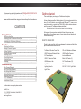
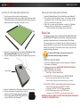
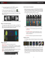
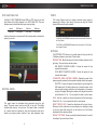
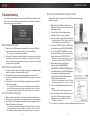
VIDEO • SWING • FORCE
User Manual
WWW.TRUGOLF.COM
VIDEO • SWING • FORCE
In this manual you will find information about TRUBALANCE FORCE PLATE
and how to use it along with the accompanying software program.
Please read this manual before using your device and keep it for future reference.
CONTENTS
Getting Started
What’s in the Box
Setting Up the TruBalance Force Plate
Installing the TruBalance Software
Basic Use
Starting the Software
Weight Transfer Diagram
Video Controls
Position Analysis Window
Drawing Tools
Post Shot Analysis
Vertical Force
Settings
Troubleshooting
No Camera Detected
No Force Plate Detected
No Hitting Mat Detected
Sony Eye Camera Driver Installation
Warranty Information
FCC Information
Intellectual Property
Getting Started
This section helps you setup your TruBalance force plate.
Unless otherwise specified, all instructions in this manual assume that you
have a TruGolf Simulator, are using Microsoft Windows 7™, have a screen
resolution equal to or greater than 1280x1024, with the device plugged in,
and the camera & TruBalance software installed.
Note: Instructions in this manual are based on default settings.
1
2
3
3
4
4
5
5
6
6
7
8
8
8
9
10
10
11
All images in this manual are simulated. Actual displays may vary
depending on the software version of your device and any changes to
the device’s settings.
WHAT’S IN THE BOX
Check to make sure that nothing was damaged in shipping and that all the
parts listed below are accounted for.
TruBalance Wireless Force Plate
CD with TruBalance Software
USB TruBalance Wireless Dongle
USB Sony Eye Camera
9V Power Adapter
Instruction Manual
USB 16’ Extension Cable
Black Side Panels (3)
USB Extension Hub
3/4” Panel Screws (12)
Light Stand
Clamp-on camera mount
Lighting Umbrella
250 W 110-130 V Light Bulb
Light Fixture
For information or support please contact:
TruGolf, Inc.
60 N. 1400 W. Centerville, Utah 84014
801-298-1997
www.trugolf.com
1
WWW.TRUGOLF.COM
VIDEO • SWING • FORCE
SETTING UP THE TRUBALANCE FORCE PLATE
1. Carefully remove the force plate from its packaging.
2. Using supplied panel screws and a phillips head screwdriver attach
the black side panels to the indicated sides (see illustration). Align top
edge of panel with the top edge of force plate - not turf.
INSTALLING THE TRUBALANCE SOFTWARE
1. Insert the TruBalance Software CD into the Disk Drive of your Windows PC.
2. The installer should automatically launch. If the installer doesn’t
automatically launch, use Windows Explorer to browse the CD/
DVD drive and launch the Setup.exe
3. Follow the on screen setup instructions to install the TruBalance
software and Sony Eye Camera driver on your Windows 7 PC.
For Sony Eye Camera driver installation instructions see Page 9.
Basic Use
The TruBalance software focuses on VIDEO ANALYSIS, WEIGHT BALANCE
and SWING ANALYSIS aspects of the Golf Swing. The following information
is intended to educate users as to the individual features of the software.
3. Position the force plate with the side labeled “This Side of Force
Plate Towards Hitting Mat” adjacent to the hitting mat.
4. Plug the TruBalance’s power adapter into the power strip your sensor
pad uses.
The contents herein are not intended to identify “ideal” golf positions or
fundamentals. Rather, they are meant to help users better understand and
improve their golf swing. This information is best used in conjunction with
a certified teaching professional.
Tip: Use the HELP button to access the manual and
instructional videos on using the software.
STARTING THE SOFTWARE
1. Launch the TruBalance software by double clicking the TruBalance
Icon located on the desktop.
2. Initializing the Force Plate. MAKE SURE THERE IS NOTHING ON
THE FORCE PLATE, then Click OK.
3. Select or Add a Player, then click OK.
Power Cable
Delete Player - Removes selected Player.
4. Select RECORD A SWING otherwise select REVIEW A SWING.
Record a Swing - Activates the system to record a swing.
Review a Swing - Displays the last recorded swing for your review.
5. RECORDING A SWING - Set your Position with the Club you’ll be using.
5. Slide the TruBalance Force Plate against the sensor pad foam edge.
6. Check to make sure the force plate is level. Use the
screws on each leg to modify the level if necessary.
7. Connect the supplied USB RECEIVER MODULE to
an open USB port on the Windows PC.
2
i. Stand on the Force Plate and ADDRESS THE BALL.
ii. Come to an UPRIGHT POSITION with even balance.
iii. Click OK when player is set or use TIMER if alone.
(Timer gives you 10 SECONDS to get into neutral position stance.
IMPORTANT: YOU WILL NEED TO DO SET POSITION ANYTIME THE GOLFER
CHANGES TO A DIFFERENT CLUB.
3
WWW.TRUGOLF.COM
VIDEO • SWING • FORCE
6. The system will remain idle until a GOLF SWING is registered.
Note: Golf club MUST cross over all three sensor rows.
7. Archive your swing by clicking the SAVE TO DISK icon.
Your shot will appear in the QUICK ACCESS archive at the top of the
screen. Use this to quickly access saved swings. Use the arrows to move
through your archive.
POSITION ANALYSIS WINDOW
Below the video window and controls is the POSITION ANALYSIS WINDOW.
This area of the software will help you visualize you how your weight
transfers through your swing at a quick glance. The software automatically
tries to identify the following key positions in your swing:
Start
Back
Top
Down
Impact
Finish
1
2
To DELETE a saved shot LONG PRESS or RIGHT CLICK on VIDEO THUMBNAIL
WEIGHT TRANSFER DIAGRAM
This diagram shows weight shift from Front to Back, Left to Right. The
pattern above shows a weight shift from center to the right toe then to the
left foot at impact and finishing balanced on the left foot.
3
These positions will be represented with a THUMBNAIL ICON from the video.
1. THUMBNAIL ICON - Click the thumbnail to jump the video to the swing
position shown.
2. ADJUSTMENT ARROWS - Adjusts the thumbnail frame by frame. If
a position in a thumbnail is slightly off, use the arrow buttons until you
find the correct the position.
3. FOOT ICON - Animates the swing forward or backward to that position.
DRAWING TOOLS
The TruBalance software includes the following tools to help you analyse
your swing:
VIDEO CONTROLS
PLAY BUTTON - Use this to play or pause your video.
TIMELINE SLIDER - This indicator identifies your position in the video.
You can drag the slider or once activated you can use the arrow keys on
the keyboard to move through the frames of video.
SPEED - The Speed button toggles between playback speeds. Use this to
slow down or speed up the playback of the video.
LOOP - This button allows you to put the video into a looping mode.
4
Circle
Square
Free Hand
Angle
Line
Eraser
Color
Drawings will stay on the video window through every swing until erased.
Erase one drawing at a time by selecting the Eraser tool and then placing
the crosshair cursor over a line drawn item and clicking on it with the
mouse. You can remove all the drawings at one time by doing a long press
on the Erase tool icon.
5
WWW.TRUGOLF.COM
VIDEO • SWING • FORCE
TEMPO
POST SHOT ANALYSIS
The BALL FLIGHT DIAGRAM shows SIDE and TOP views of your ball
flight. Below the ball flight diagram is the SHOT ANALYSIS. This area
displays some technical data about your swing including:
Launch
Ball Speed
Direction
Backspin
Side Spin
Club Speed
Club Face
Club Path
Use this information in conjunction with the force plate data to evaluate the
quality of your shot.
The Tempo Diagram helps you achieve consistent swing tempo by
measuring the timing of your swing. These are set using the Position
Analysis Window and can be adjusted.
The BACK or BACKSWING measures the time from the Start Position to
the Top Position.
The DOWN or DOWNSWING measures the time from the Top Position
to the Impact Position.
SETTINGS
The SETTINGS ICON allows you to modify values to help you tailor the
TruBalance software to your swing. These include:
RECORD TIME - Modify the amount of time the software allocates for the
golf swing. This can be done with two sliders.
PRE IMPACT DURATION SLIDER - Controls the amount of time
recorded before impact.
POST IMPACT DURATION SLIDER - Controls the amount of time
recorded after impact.
*Some of these values are estimated.
CONNECTED SWING CAPTURE CAMERA - Displays the model of the
camera currently connected to the computer and being used by the program.
SHUTTER - Controls the amount of light allowed to come through the
USB camera lens. This setting allows you to freeze the motion of the
club and golfer reducing motion blur and is dependent on the amount
of light on the subject. More light is needed on the subject the lower the
value. Default is 60. Tip - You can adjust this while in record mode.
VERTICAL FORCE
This graph shows the downward force generated during the golf
swing. The graph moves from the start (left) to the right. The bottom
indicates less pressure, the top more. The impact frame is identified
by a square mark. An example of using this information would be to
monitor your impact position relative to your peak downward force.
6
GAIN - Use this to amplify or reduce the brightness of the video image.
Default is 50. Tip - You can adjust this while in record mode.
RESET FORCE PLATE - Resets the default state of the board to zero.
Before you do this, make sure no one is standing on or anything is resting
on the force plate. After doing this you will need to do a Set Position
adjustment before capturing swings.
DEFAULT SETTINGS - Shows you what the default values are for each of
the settings if you need to reset them.
7
WWW.TRUGOLF.COM
VIDEO • SWING • FORCE
Troubleshooting
SONY EYE CAMERA DRIVER INSTALLATION
If you see this message box after starting the TruBalance software, then
one or more of the TruBalance system devices has not been detected as
being connected to your computer.
Follow these steps to ensure that your PS3Eye Camera drivers get
installed correctly.
1. Make sure the TruBalance software has
been fully installed on your computer before
continuing to step 2
2. Connect the Sony Eye Camera to any
available USB port on your computer
3. Once connected, navigate to Device Manager
Press the Windows START button, Right-click
COMPUTER then select PROPERTIES
NO CAMERA DETECTED
1. Make sure the USB camera is connected to an on-board USB port
as it needs to access power via a PC’s on-board USB port.
Do not connect it via the extension USB Hub.
2. During the TruBalance software installation process you should have
gone through a camera driver installation. If you did the driver install
and have the camera connected correctly, then contact Tech Support
to help resolve the problem.
NO FORCE PLATE DETECTED
1. Confirm that the 9 volt power supply is plugged into a powered outlet
and the red light on the power supply is lit up.
2. Confirm that the power connector is plugged into the force plate
controller box located on the underside of the force plate. (See diagram in
Setup section.)
3. Check that the wireless USB dongle is plugged into an active USB
port on the computer.
If it is not then exit TruBalance and plug the USB dongle in another USB port
and see if Windows detects the dongle and installs the driver, then restart
the TruBalance software. Contact Tech Support if the error is not resolved.
NO HITTING MAT DETECTED
1. Make sure the serial cable is securely connected to the hitting mat.
2. Verify that the serial cable from the hitting mat is securely connected
to the USB to Serial adapter and that the adapter is plugged into an
active USB port on the computer.
4. From the CONTROL PANEL HOME column
on the left side, select DEVICE MANAGER
5. Once in the DEVICE MANAGER, you will
see the USB camera with a yellow warning
symbol listed under OTHER DEVICES
Right-click on this device to bring up a menu
and select UPDATE DRIVER SOFTWARE…
6. When asked to search for the driver
software, select the BROWSE MY
COMPUTER FOR DRIVER SOFTWARE option
7. In the next window, click the BROWSE button
and navigate to the following location: C:\
Program Files\TruGolf\TruBalance\Drivers\
Sony Playstation Eye Camera
With that folder highlighted, click the ‘OK’ button
and subsequently the ‘Next’ button to continue
8. This will have a Windows Security window
pop up
Click on ‘Install this driver software anyway’
9. This will install your Sony Eye Camera and
show you a ‘Windows has successfully
updated your driver software’ window
Click the ‘Close’ button
10. Your Sony Eye Camera is now fully installed and ready to be used
If it is not then exit TruBalance and plug the USB dongle in another USB port
and see if Windows detects the dongle and installs the driver, then restart
the TruBalance software. Contact Tech Support if the error is not resolved.
8
9
WWW.TRUGOLF.COM
VIDEO • SWING • FORCE
WARRANTY INFORMATION
INTELLECTUAL PROPERTY
All products sold by TruGolf Inc. are warranted against defects in material
and workmanship for a period of one (1) years from the date of shipment
within North America, and for a period of six (6) months from the date
of shipment to outside of North America. If you believe any TruGolf Inc.
product you have purchased has a defect in material or workmanship
or has failed during normal use within the warranty period, please
contact TruGolf Inc. at 877-711-6691 for assistance. If product repair or
replacement is necessary, the Customer will be solely responsible for
all shipping charges, freight, insurance and proper packaging to prevent
breakage in transit, whether or not the product is covered by this warranty.
This warranty does not apply to defects resulting from any Customer
actions, such as mishandling, improper interfacing, operation outside of
design limits, misapplication, improper repair, or unauthorized modification.
No other warranties are expressed or implied. TruGolf Inc specifically
disclaims any implied warranties of merchantability or fitness for a specific
purpose. TruGolf Inc’s liability shall be limited to the actual purchase price
of any defective unit or units of equipment to which a claim is made, and
shall in no event include the Customer’s manufacturing costs, lost profits or
goodwill, or any other direct, indirect, special, incidental or consequential
damages whether based on contract, tort or other legal theory. TruGolf
Inc shall not be liable for normal manufacturing defects or customary
variances from specifications.
FCC INFORMATION
Contains FCC ID: OUR-XBEE
The enclosed device complies with Part 15 of the FCC Rules.
Operation is subject to the following two conditions:
(i.) this device may not cause harmful interference and
(ii.) this device must accept any interference received,
including interference that may cause undesired operation.
RF Exposure WARNING: To satisfy FCC RF exposure requirements
for mobile transmitting devices, a separation distance of 20 cm or more
should be maintained between the antenna of this device and persons
during device operation. To ensure compliance, operations at closer
than this distance is not recommended. The antenna used for this
transmitter must not be co-located in conjunction with any other antenna
or transmitter.
10
All Intellectual Property, as defined below, owned by or which is otherwise
the property of TruGolf or its respective suppliers relating to the TruBalance
Force Plate, including but not limited to, accessories, parts, or software
relating there to (the “TruBalance Force Plate”), is proprietary to TruGolf
and protected under federal laws, state laws, and international treaty
provisions. Intellectual Property includes, but is not limited to, inventions
(patentable or unpatentable), patents, trade secrets, copyrights, software,
computer programs, and related documentation and other works of
authorship. You may not infringe or otherwise violate the rights secured by
the Intellectual Property.
Moreover, you agree that you will not (and will not attempt to) modify,
prepare derivative works of, reverse engineer, decompile, disassemble,
or otherwise attempt to create source code from the software. No title to or
ownership in the Intellectual Property is transferred to you. All applicable
rights of the Intellectual Property shall remain with TruGolf Inc. and its
suppliers.
Disclaimer of Warranties; Exclusion of Liability
EXCEPT AS SET FORTH IN THE WARRANTY CONTAINED ON THE
WARRANTY PAGE ENCLOSED WITH THE PRODUCT, THE PURCHASER
TAKES THE PRODUCT “AS IS”, AND TRUGOLF MAKES NO EXPRESS OR
IMPLIED WARRANTY OF ANY KIND WHATSOEVER WITH RESPECT TO
THE PRODUCT, INCLUDING BUT NOT LIMITED TO THE MERCHANTABILITY
OF THE PRODUCT OR ITS FITNESS FOR ANY PARTICULAR PURPOSE
OR USE; THE DESIGN, CONDITION OR QUALITY OF THE PRODUCT; THE
PERFORMANCE OF THE PRODUCT; THE WORKMANSHIP OF THE PRODUCT
OR THE COMPONENTS CONTAINED THEREIN; OR COMPLIANCE OF THE
PRODUCT WITH THE REQUIREMENTS OF ANY LAW, RULE, SPECIFICATION
OR CONTRACT PERTAINING THERETO. NOTHING CONTAINED IN THE
INSTRUCTION MANUAL SHALL BE CONSTRUED TO CREATE AN EXPRESS
OR IMPLIED WARRANTY OF ANY KIND WHATSOEVER WITH RESPECT TO
THE PRODUCT. IN ADDITION, TRUGOLF SHALL NOT BE LIABLE FOR ANY
DAMAGES OF ANY KIND RESULTING FROM THE PURCHASE OR USE OF
THE PRODUCT OR ARISING FROM THE BREACH OF THE WARRANTY,
INCLUDING INCIDENTAL, SPECIAL OR CONSEQUENTIAL DAMAGES, OR
LOSS OF ANTICIPATED PROFITS OR BENEFITS.
11
™
D R I V I N G
R E A L I T Y
60 NORTH 1400 WEST
CENTERVILLE, UT 84014
CUSTOMER SUPPORT
801.677.1123
877.711.6691
SALES
801.298.1997
866.711.4653
WWW.TRUGOLF.COM