1
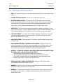
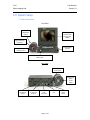
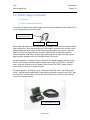
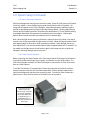
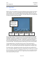
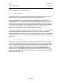
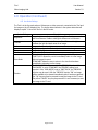
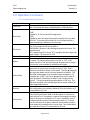
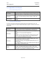
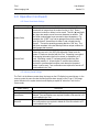
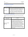
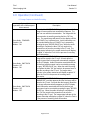
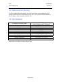
R e m o t e V i s u a l I n s p e c t i o n Product Manual iTool Video Imaging Hub (part of the iTool System An Intelligent Inspection System) www.itconceptsworld.com [email protected] iTool Video Imaging Hub User Manual Version 1.0 Introduction Thank you for purchasing the iTool Video Imaging Hub! The iTool is the heart of each iTool inspection system and combines illumination, image control and management functions. The iTool system is easily transported, uncomplicated to setup and straightforward to use. The iTool employs cutting edge technology to deliver Remote Visual Inspection (RVI) results. This manual gives you the information necessary to operate and maintain the iTool Video Imaging Hub. Page 2 of 26 iTool Video Imaging Hub User Manual Version 1.0 Table of Contents 1.0 Warnings and Precautions 2.0 System Overview 3.0 System Setup 3.1 iTool Nomenclature 3.2 iSeries Videoscope Nomenclature 3.3 First Steps 3.31 iSeries Videoscope Operation 3.32 Video Camera Operation 3.33 External Devices 3.4 Saving Digital Video and Audio Data 4.0 Operation 4.1 System Status Bar 4.2 System Menu Bar 4.21 Live Mode Settings 4.22 Frame View Mode Settings 4.23 Memory Mode Settings 4.3 Image Capture and Audio Recording 4.4 Time-lapse Video Recording 4.5 File Management 4.51 CompactFlash® (CF) Card 4.52 File Commander Software 5.0 User Serviceable Parts 5.1 Lamp Replacement 6.0 Maintenance/Cleaning 7.0 Specifications 8.0 Service 9.0 Warranty 10.0 Trademarks 11.0 About IT Concepts Page 3 of 26 iTool Video Imaging Hub User Manual Version 1.0 1.0 Warnings and Precautions READ - For operator safety, be sure to read and understand this user manual before using the iTool. POSSIBLE EXPLOSION HAZARD - Do not use in explosive environments. ELECTRICAL SHOCK HAZARD - The top cover of the iTool should never be removed. Electrical shock hazard exists due to high internal voltage. There are no user serviceable parts inside the iTool except for the lamp, which is accessible through the front light source panel. Direct all service requirements to an IT Concepts Service Center. VENTILATION - The iTool must have adequate ventilation to prevent overheating. Do not cover or cloak the iTool. To ensure adequate airflow, be sure to provide a minimum 2 inch (5.1cm) distance between the front and rear of the iTool chassis and any solid objects. LAMP REPLACEMENT - Use caution when replacing the lamp, it may be hot. Only use IT Concepts 24W Metal Halide Arc Lamp part number: 401-0036 for lamp replacement. Refer to “Lamp Replacement” section. LAMP INSTALLATION - Do not operate the iTool without a lamp installed, damage to the iTool may result. EARTH GROUND REQUIRED - ELECTRICAL SHOCK HAZARD - Proper use of the iTool requires the presence of a protective earth ground path at the AC power source. Use of two-conductor extension cords or any other actions that may result in the loss of this ground path are in violation of the product’s safe operating requirements. WARNING - ULTRAVIOLET, INFRARED, AND INTENSE VISIBLE RADIATION EMITTED FROM THE LAMP SOURCE. SKIN OR EYE INJURY MAY RESULT. 1. Avoid exposure of eyes and skin to lamp while in operation. 2. Do not operate the iTool light source without a light guide cable installed. 3. Turn off the iTool light source or turn the brightness control to minimum when changing Videoscope tip adapters and objective lenses. VIDEOSCOPE/VIDEO CAMERA DISCONNECTION - Always turn off the iTool before disconnecting a Videoscope or Video Camera. WARNING – Use of the iTool in a manner not specified by the manufacturer may impair the product’s ability to protect the user from harm. WARNING – A Videoscope used with the iTool should never come in direct contact with any voltage or current source. Damage to the product and/or electrical shock to the operator may result! Page 4 of 26 iTool Video Imaging Hub User Manual Version 1.0 2.0 System Overview The iTool Video Imaging Hub is intended for use with IT Concepts Videoscopes, video cameras and peripheral RVI video devices. The iTool is a field portable unit that combines light source, image control and management functions. A High Intensity Discharge (HID) 24W Metal Halide lamp provides powerful light output and enables true-color images to be viewed in remote dark areas. The images produced by a Videoscope or video camera are displayed on an LCD (Liquid Crystal Display). Digital video and audio data can be recorded without messy cables or advanced computer knowledge. The iTool will display live images and record still images and time-lapse video. The iTool is also capable of recording audio information associated with a still image or time-lapse video. Data is saved to a Type I CompactFlash® (CF) card. Saved images and time-lapse video can be viewed on the iTool’s integral LCD display. Data can be transferred to a PC (Personal Computer) via the CF card or the iTool’s USB (Universal Serial Bus) interface. The utility of the iTool is enhanced by AC (100-240V) and DC (12V) power options. The iTool can be operated with a 12V Nickel Metal Hydride (NiMH) power belt which makes it very portable and particularly suitable for RVI tasks in out-of-the-way locations. Page 5 of 26 iTool Video Imaging Hub User Manual Version 1.0 3.0 System Setup 3.1 iTool Nomenclature Front View 24W Metal Halide Light Source Bright, highresolution fold up/down LCD display Light guide plug receptacle CompactFlash card slot Light source intensity control Videoscope/Video Camera umbilical cable socket Rear View iTool power on/off switch Light source power on/off switch Video in/out for external devices Audio in/out for use with head set USB interface for PC connection Page 6 of 26 Foot switch port 12V DC power socket iTool Video Imaging Hub User Manual Version 1.0 3.0 System Setup 3.1 iTool Nomenclature Keypad Splash proof keypad On screen display on/off key Menu key 3.2 iSeries Videoscope Nomenclature Handpiece Handpiece articulation controls and articulation brakes Armored umbilical cable 4-way distal tip articulation Insertion tube with external wear resistant tungsten braid Ground connector Bending section Strain relief protection Light guide plug (light guide plug adapter detached) Connector for short 5-pin Light Guide Plug Connector Cable Page 7 of 26 Image capture button iTool Video Imaging Hub User Manual Version 1.0 3.0 System Setup (continued.) 3.3 First Steps 3.31 iSeries Videoscope Operation To use the iTool with an iSeries Videoscope, open the case and identify the short 200mm (7.87 in) 5-pin light guide plug connector cable. Short 5-pin Light Guide Plug Connector Cable White end Plain end Remove the Videoscope from the case holding the handpiece with one hand and the insertion tube with the other. Place the Videoscope on a flat surface. Insert the white end of the 5-pin light guide plug connector cable into the Videoscope light guide plug connector. Insert the plain end of the 5-pin light guide plug connector cable into the iTool Videoscope/Video Camera umbilical cable socket. Insert the light guide plug into the light source light guide plug receptacle located at the front of the light source in the center. AC power operation - If using AC power, connect the AC adapter (supplied with the iTool) to the iTool 12V DC power socket and the AC adapter power cord to a 100/110V or 220/240V outlet. Align the red dots on the AC adapter connector and iTool 12V DC power socket to ensure that the connector is inserted correctly. DC power operation - If using DC power, connect the Power Belt to the iTool 12V DC power socket. A Nickel Metal Hydride (NiMH) Power Belt is an optional accessory for the iTool. Align the red dots on the Power Belt connector and iTool 12V DC power socket to ensure that the connector is inserted correctly. iTool with NiMH Power Belt Page 8 of 26 iTool Video Imaging Hub User Manual Version 1.0 3.0 System Setup (continued.) 3.31 iSeries Videoscope Operation Verify that all plugs and connectors are securely in place. Move the iTool power on/off switch to the on (I) position. Move the light source power on/off switch to the on (I) position. An image will now appear on the iTool LCD display. Adjust the light source intensity control to provide an appropriate amount of light for the object being viewed. The lamp will deliver an intense amount of white light with a correlated color temperature (CCT) over 5400K providing true daylight illumination for improved color rendering and color balance. Videoscopes perform best in remote enclosed areas where there is no ambient light. Note: When the light source power on/off switch is moved to the on (I) position it can take a second or two for the lamp inside the light source to initiate. When the lamp has started it will take approximately 30 seconds to reach its maximum intensity. When the light source has been switched off, it can only be restarted after a delay of approximately 10 to 15 seconds. Do not rapidly turn the light source off and back on again, as the lamp may not re-ignite and damage to the lamp and light source may occur. 3.32 Video Camera Operation Before connecting any Video Camera to the iTool ensure that the iTool power on/off switch is in the off (0) position and the light source power on/off switch is in the off (0) position. The iTool will not operate correctly if an iSeries Videoscope is connected to the iTool at the same time as a Video Camera. To use the iTool with an IT Concepts Video Camera insert the plain end of the 5-pin video camera connector cable into the iTool Videoscope/Video Camera umbilical cable socket. Verify that all plugs and connectors are securely in place. Connect the Video Camera to a power source. Move the iTool power on/off switch to the on (I) position. IT Concepts Color CCD Video Camera (this camera is most commonly used for RVI applications with a video adapter and a rigid Borescope or a flexible Fiberscope, it is shown here without any of these items) Page 9 of 26 iTool Video Imaging Hub User Manual Version 1.0 3.0 System Setup (continued.) 3.32 Video Camera Operation To use the iTool with a Video Camera other than an IT Concepts unit, connect the camera’s video out connector to the “V-IN” port on the rear of the iTool. Verify that all plugs and connectors are securely in place. Connect the Video Camera to a power source. Move the iTool power on/off switch to the on (I) position. 3.33 External Devices The iTool can be used with a number of external devices including, but not limited to, a video monitor, video cassette recorder (VCR), digital video recorder (DVR) and portable hard drive (data storage device). All of these devices connect to either the “V-IN” or “V-OUT” port on the rear of the iTool. The iTool will not operate correctly if an iSeries Videoscope is connected to the iTool at the same time as an external device is connected to the “V-IN” port on the rear of the iTool. Before operation, verify that all plugs and connectors are securely in place. Connect the external device to a power source. Move the iTool power on/off switch to the on (I) position. 3.4 Saving Digital Video and Audio Data The iTool can be used to record still images and time-lapse video. The iTool is also capable of recording audio information associated with a still image or time-lapse video. All data is stored on a Type I CompactFlash card (sometimes referred to as Standard CompactFlash). Saved images and time-lapse video can be viewed on the iTool’s integral LCD display. Data can be transferred to a PC via the CF card or the iTool’s USB interface. To record audio information and listen to recordings an audio head set needs to be connected to the iTool. The microphone plug from the head set should be inserted into the “MIC” jack at the rear of the iTool. The earphone plug from the head set should be inserted into the “FON” jack at the rear of the iTool. Only FAT16 (File Allocation Table) 16-bit file system CF cards can be used with the iTool. Page 10 of 26 iTool Video Imaging Hub User Manual Version 1.0 4.0 Operation 4.1 System Status Bar When the iTool is on, the operator may choose to display the system status bar at the bottom of the LCD display. The iTool is most typically used with the system status bar in view. The system status bar may be removed from sight by pressing the blue “DISPLAY” key at the left hand end of the front row of keys on the keypad. The system status bar can be brought back into view by pressing the same button again. LCD display with system status bar in view (the LCD display is shown without an iSeries Videoscope or a Video camera connected to the iTool) CF card capacity indicator File number indicator Image status indicator Supply voltage indicator Image orientation indicator If a CF card has not been inserted into the CF card slot on the front of the iTool a “NO CARD” message will be displayed. If a damage card or an incorrectly formatted card is inserted a “BAD CARD” message will be displayed. If a CF card has been incorrectly inserted (forced or inserted with inadequate effort) a “NO CARD” or “BAD CARD” message will be displayed. If any of the situations described above occurs a small red indicator light on the left side of the CF card slot will flash. This indicator light does not flash when a CF card is correctly installed. CF card capacity indicator - this indicator shows how much CF card memory space is available. The CF card is empty when the rectangular space is white and no status bar can be seen. The CF card is full when the black status bar completely fills the rectangular space. File number indicator - this indicates the number of the next file that can be saved to the CF card. If the number is 00000001 it means that no images have been saved to the CF card and the CF card is empty. If the number is 00000020 (example), it does not necessarily mean that there are twenty images stored on the CF card. Images may have been deleted from the CF card’s memory after they were saved. Page 11 of 26 iTool Video Imaging Hub User Manual Version 1.0 4.0 Operation (Continued.) 4.1 System Status Bar Image status indicator - this indicator provides confirmation of whether the image is Live “L” a view of a Frame “F” or a view of an image stored in the CF card Memory “M”. Supply voltage indicator - this indicator shows the iTool supply voltage. When the iTool is being operated with an AC supply this number should remain pretty stable and the indicator has limited value. However, when the iTool is being operated with a DC supply this number will decrease as the strength of the DC supply diminishes and the indicator is very valuable. The iTool will not operate when the supply voltage reaches 10V. It is important to pay attention to this indicator when the iTool is operated with a DC supply. Image orientation indicator - this indicates the orientation of a live image. If the indicator letter is inverted or transposed it means that the image is inverted or transposed. Inverted or transposed images can be saved to the CF card, but the orientation indicator is not saved with the file. Image orientation is changed by pressing the up (▲), down (▼), left (◄) and right (►) keys. 4.2 System Menu Bar When the system status bar is shown on the display, the system menu bar can be brought into view by pressing the blue “MENU” located in the center of the first row of keys on the key pad. The system menu bar is used to manage iTool performance. When the system menu bar is in view the up (▲) and down (▼) keys are used to scroll through the system settings. The left (◄) and right (►) keys are used to adjust (increase/decrease) the system settings. When settings have been changed it is necessary to confirm the new settings by pressing the “OK” key. The system menu bar can be removed from sight by pressing the blue “MENU” key. Page 12 of 26 iTool Video Imaging Hub User Manual Version 1.0 4.0 Operation (Continued.) 4.21 Live Mode Settings The iTool is in the live mode when a Videoscope or video camera is connected to the iTool and the image on the LCD display is live. The image status indicator in the system status bar will display a capital “L” when the iTool is in the live mode. System Setting Brightness Contrast Color Hue Sharpness Volume Save Mode Preview Description Image brightness adjustment. Brightness - The effect by means of which an observer is able to distinguish differences in luminance. Image contrast adjustment. Contrast - The difference in brightness between the light and dark areas of an image. Image color intensity adjustment. Image hue adjustment. Color adjustment toward red or green. Image clarity adjustment. Volume level adjustment. Determines the method used to save an image to the CF card. “ONE TOUCH” allows the user to immediately return to a live image after an imaged is saved. “STANDARD” allows the user to return to the view that has been saved before returning to a live image. The “SAVE MODE” function overrides the “PREVIEW” function. If the “SAVE MODE” is set to “STANDARD” the “PREVIEW” setting is not required. If the “SAVE MODE” is set to “ONE TOUCH” the “PREVIEW” function may be used. With the “PREVIEW” function “ON” an image will be available to be viewed immediately after it has been captured. The “OK” key may then be pressed to save the image to the CF card. The yellow “CANCEL” key may be pressed if it is not necessary to save the image to the CF card. Page 13 of 26 iTool Video Imaging Hub User Manual Version 1.0 4.0 Operation (Continued.) 4.21 Live Mode Settings (Continued.) System Setting Frame Size Num Fields File Format Date and Time Marker Marker Editor Erase All Format Card Description Determines the image size when an image is saved to the CF card. The iTool provide two options 640x480 pixels or 320x240 pixels. Determines the number of video fields used when an image is saved. “ONE” Suitable for 99.9% (may be all) RVI applications. “TWO” Suitable for when the target object and the viewing device are both VERY still. This mode may be used if the iTool is employed with a video camera that is attached to a microscope. Determines the file format when images are saved to the CF card. The iTool provides two file format options: BMP (BitMaP), Windows’ native bitmapped graphics file format. File extension bmp. TIFF (Tagged Image File Format), TIFF is a popular format for high color depth images. File extension tif or tiff. Date and time adjustment. This function allows users to add comments specific to an image to be saved. The marker setting options are “ON” or “OFF”. If the marker function is “ON” text comments will be saved with an image. This function is only available for 640x480 pixel images. This function allows users to edit the text comments that will be saved with an image when the marker function is “ON”. Eleven characters (numbers or letters) can be saved. The left (◄) and right (►) keys are used to move from one character to another. The ten white number/letter keys are used to input characters. For example, the “3 DEF” key can be pressed once for the letter D, twice for letter E, three times for letter F and a fourth time for figure 3. The text is saved by pressing the blue "OK” key. The last three numbers in the text block provide a unique number for each image that is saved. Allows all of the files saved to a CF card to be permanently deleted. Two confirmations are required to delete all of the files saved to a CF card installed in the iTool. New CF cards are almost always formatted by the manufacturer. Only FAT16 (File Allocation Table) 16-bit file system CF cards can be used with the iTool. Formatting is a method of arranging information that is to be stored or displayed to a CF card. Formatting a used CF card permanently erases any files previously saved to it. A brandnew CF card that has not been received in a preformatted condition must always be formatted before it can be used. Two confirmations are required to format a CF card installed in the iTool. Page 14 of 26 iTool Video Imaging Hub User Manual Version 1.0 4.0 Operation (Continued.) 4.22 Live Mode Settings (Continued.) System Setting Time Lapse Change Dir Fabric Settings Description Determines the amount of time-lapse between two images in a timelapse video sequence. The time-lapse can be from 0 to 99 seconds. Allows the user to select the CF card directory or folder where files will be saved. The iTool provides two directory options, “VISIE3” and “ROOT”. Permits the user to return all iTool settings to the factory default settings. 4.22 Frame View Mode Settings The iTool is in the Frame mode when an image is about to be saved to the CF card. The image status indicator in the system status bar will display a capital “F” when the iTool is in the Frame mode. System Setting Frame Size Num Fields File Format Date & Time Marker Description Determines the image size when an image is saved to the CF card. The iTool provide two options 640x480 pixels or 320x240 pixels. Determines the number of video fields used when an image is saved. “ONE” Suitable for 99.9% (may be all) RVI applications. “TWO” Suitable for when the target object and the viewing device are both VERY still. The mode may be used if the iTool is employed with a video camera that is attached to a microscope. Determines the file format when images are saved to the CF card. The iTool provides two file format options: BMP (BitMaP), Windows’ native bitmapped graphics file format. File extension bmp. TIFF (Tagged Image File Format), TIFF is a popular format for high color depth images. File extension tif or tiff. Date and time adjustment. This function allows users to add comments specific to an image to be saved. The marker setting options are “ON” or “OFF”. If the marker function is “ON” text comments will be saved with an image. This function is only available for 640x480 pixel images. Page 15 of 26 iTool Video Imaging Hub User Manual Version 1.0 4.0 Operation (Continued.) 4.22 Frame View Mode Settings System Setting Marker Editor Format Card Description This function allows users to edit the text comments that will be saved with an image when the marker function is “ON”. Eleven characters (numbers or letters) can be saved. The left (◄) and right (►) keys are used to move from one character to another. The ten white number/letter keys are used to input characters. For example, the “3 DEF” key can be pressed once for the letter D, twice for letter E, three times for letter F and a fourth time for figure 3. The text is saved by pressing the blue "OK” key. The last three numbers in the text block provide a unique number for each image that is saved. New CF cards are almost always formatted by the manufacturer before they are sold. Only FAT16 (File Allocation Table) 16-bit file system CF cards can be used with the iTool. Formatting is a method of arranging information that is to be stored or displayed to a CF card. Formatting a used CF card permanently erases any files previously saved to it. A brand-new CF card that has not been received in a preformatted condition must always be formatted before it can be used. Two confirmations are required to format a CF card installed in the iTool. 4.23 Memory Mode Settings The iTool is in the Memory mode when the image on the LCD display is a saved image. In the memory mode the user can view the files that have been stored on the CF card. The image status indicator in the system status bar will display a capital “M” when the iTool is in the Frame mode. System Setting Volume Erase Frame Erase All Description Volume level adjustment. Allows the file being viewed on the LCD display to be permanently deleted. Two confirmations are required to delete a file saved to a CF card installed in the iTool. Allows all of the files saved to a CF card to be permanently deleted. Two confirmations are required to delete all of the files saved to a CF card installed in the iTool. Page 16 of 26 iTool Video Imaging Hub User Manual Version 1.0 4.0 Operation (Continued.) 4.23 Memory Mode Settings System Setting Format Card Description New CF cards are almost always formatted by the manufacturer before they are sold. Only FAT16 (File Allocation Table) 16-bit file system CF cards can be used with the iTool. Formatting is a method of arranging information that is to be stored or displayed to a CF card. Formatting a used CF card permanently erases any files previously saved to it. A brand-new CF card that has not been received in a preformatted condition must always be formatted before it can be used. Two confirmations are required to format a CF card installed in the iTool. 4.3 Image Capture and Audio Recording The Save Mode, Preview, and Marker system settings control iTool image capture operation options. Image Capture Options (operation with a Videoscope or video camera) Save Mode: STANDARD Preview: ON Marker: OFF Description When the blue “CAPTURE SAVE” key is pressed once the live image is frozen and a “SAVE FRAME?” prompt appears. If the user wishes to save the image this can now be accomplished by pressing the blue “OK” key once. If the Marker setting is “OFF” a prompt will appear to remind the user that a text annotation will not be saved with the image. The saved image will remain on the display until the red “CANCEL” key is pressed once. Audio information can be recorded before the red “CANCEL” key is pressed by pressing the gray “RECORD PAUSE” key. When the audio recording is complete the blue “OK” key needs to be pressed once to save the recording to the CF card. The image status indicator in the system status bar will display a capital “A” when the iTool is in the process of recording audio information. Page 17 of 26 iTool Video Imaging Hub User Manual Version 1.0 4.0 Operation (Continued.) 4.3 Image Capture and Audio Recording Image Capture Options (operation with a Videoscope or video camera) Save Mode: STANDARD Preview: ON Marker: ON Save Mode: ONE TOUCH Preview: OFF Marker: ON Save Mode: ONE TOUCH Preview: OFF Marker: OFF Description When the blue “CAPTURE SAVE” key is pressed once the live image is frozen and the text annotation will appear. The user can now edit the text annotation. The image with the text annotation is saved by pressing the blue “OK” key once. The saved image will remain on the display until the red “CANCEL” key is pressed once. Audio information can be recorded before the red “CANCEL” key is pressed by pressing the gray “RECORD PAUSE” key. When the audio recording is complete the blue “OK” key needs to be pressed once to save the recording to the CF card. The image status indicator in the system status bar will display a capital “A” when the iTool is in the process of recording audio information. When the blue “CAPTURE SAVE” key is pressed once the live image will be saved to the CF card. Seconds after the image is saved the live image will automatically reappear on the LCD display. Audio information associated with the file that has just been saved can be recorded by pressing the gray “RECORD PAUSE” key. When the audio recording is complete the blue “OK” key needs to be pressed once to save the recording to the CF card. The image status indicator in the system status bar will display a capital “A” when the iTool is in the process of recording audio information. When the blue “CAPTURE SAVE” key is pressed once a “MARKER OFF” reminder appears and the live image will be saved to the CF card. Seconds after the image is saved the live image will automatically reappear on the LCD display. Audio information associated with the file that has just been saved can be recorded by pressing the gray “RECORD PAUSE” key. When the audio recording is complete the blue “OK” key needs to be pressed once to save the recording to the CF card. The image status indicator in the system status bar will display a capital “A” when the iTool is in the process of recording audio information. Page 18 of 26 iTool Video Imaging Hub User Manual Version 1.0 4.0 Operation (Continued.) 4.3 Image Capture and Audio Recording There is an additional and very convenient way to capture images when the iTool is used with an iSeries Videoscope. The small round blue image capture button located on the handpiece of an iSeries Videoscope can be used to capture images. If the button is pressed once, a “SAVE FRAME?” prompt will appear on the LCD display. If the user decides to save the image, pressing the image capture button for a second time will save the image to the CF card and the live image will automatically reappear on the LCD display. If the user decides not to save the image it if necessary to press the red “CANCEL” key on the iTool keypad. iTool audio recordings are saved as WAV (Waveform audio format) files. WAV is a Microsoft and IBM audio file format standard for storing audio on personal computers. File extension wav. 4.4 Time-lapse Video Recording The process to record a time-lapse video sequence is very straightforward. With the iTool in the live mode press the gray “RECORD PAUSE” key on the keypad to begin recording. Press the blue “OK” key to end the recording and save the recording to the CF card. The image status indicator in the system status bar will display a capital “A” when the iTool is in the process of recording a time-lapse video sequence. Additionally, a small green indicator light on the left side of the CF card slot will illuminate when the iTool is in the process of recording a time-lapse video sequence. The Time Lapse system setting determines the amount of time between two images in a time-lapse video sequence. The time-lapse can be from 0 to 99 seconds. iTool time-lapse video files are recorded in AVI (Audio Video Interleave) which is a multimedia container format introduced by Microsoft as part of the Video for Windows technology. File extension avi. Page 19 of 26 iTool Video Imaging Hub User Manual Version 1.0 4.0 Operation (Continued.) 4.5 File Management 4.51 CompactFlash® (CF) Card The iTool is in the Memory mode when the image on the LCD display is a saved image. In the memory mode the user can view the he image and time-lapse video files that have been stored on the CF card. The image status indicator in the system status bar will display a capital “M” when the iTool is in the Memory mode. Image and time-lapse video files saved to the CF card can be viewed by pressing the gray “MEMORY SEARCH” key on the keypad. When this key is pressed the most recent file saved will appear on the LCD display. The up (▲) and down (▼) keys are used to scroll through the images stored on the CF card. It is also possible to search the CF card for a specific file. This accomplished by pressing the gray “MEMORY SEARCH” key when the iTool is in the Memory mode. When the gray “MEMORY SEARCH” key is pressed the system status bar will display eight zeros and a capital “S”. To search for a file it is necessary to use the white number/letter keys to input the file number. When the file number has been entered the gray “MEMORY SEARCH” key can be pressed to search for the file. If the file is found, the file will appear on the LCD display. If the file is not found, a “NOT FOUND” prompt will appear in the system status bar. When the iTool is in the Memory mode it is possible to display the system status bar at the bottom of the LCD display or remove the system status bar from sight by pressing the blue “DISPLAY” key. The system status bar can be brought back into view by pressing the same button again. When the system status bar is shown on the display, the system menu bar can be brought into view by pressing the blue “MENU” located in the center of the first row of keys on the key pad. Any size of Type I CF card can be used with the iTool. However, only a maximum of 500 files can be saved to any single CF card. When the memory of a CF card is full, a small red indicator light on the left side of the CF card slot will illuminate. If a user attempts to save an image to a full CF card, a “CARD FULL” prompt will appear in the system status bar. Image File Format Image Size BMP BMP TIFF TIFF 320x240 640x480 320x240 640x480 512MB CF Card Number of Images Up to 500 Up to 500 Up to 500 Up to 500 128MB CF Card Number of Images Up to 500 In the region of 130 Up to 500 In the region of 130 Note: A single 320x240 file is 231kB. A single 640x480 file is 922kB. Many CF cards have a capacity which exceeds iTool capability. When a CF card is used with the iTool a maximum of 500 files can be stored on the card. Any size of CF card can be used with the iTool, but the iTool file capacity is limited to 500 files. Page 20 of 26 iTool Video Imaging Hub User Manual Version 1.0 4.0 Operation (Continued.) 4.52 File Commander Software There are two ways to transfer files from the iTool to a PC. Data can be transferred to a PC (Personal Computer) via the CF card or the iTool’s USB (Universal Serial Bus) interface. CF card transfer - Remove the CF card from the iTool and insert it into a CF card reader that is connected to the PC. USB transfer - Install the simple iTool File Commander software on the PC and connect the iTool to the PC by means of the iTool USB interface. The iTool should be switched off when the USB cable is being connected between the iTool and a PC. When the iTool is connected to a PC and the software is running it is possible to copy and delete the files stored on the CF card. 5.0 User Serviceable Parts The iTool is a robust and portable Video Imaging hub that has been designed for use in RVI environments that are often space restricted, wet and dirty. As such the iTool has been designed to have the fewest possible number of user serviceable parts. 5.1 Lamp Replacement Use caution when replacing the lamp, it may be hot. Before attempting to replace the lamp, remove power from the iTool by disconnecting the power cord at the rear of the unit and allow the lamp to cool for 15-20 minutes. Lamps operate at elevated temperatures and burns will result from handling before sufficient cooling has taken place. When the lamp is cool, remove the two screws on the front plate of the light source and extract the lamp module from the body of the light source. For optimum performance, avoid handling the bulb or reflector. Fingerprints or other contaminates on the glass may degrade lamp performance or cause premature failures. Release the mechanism that holds the lamp in place and slide the lamp sideways out of front plate assembly. Separate the lamp from the two pin electrical connector by firmly holding the ceramic base of the lamp with one hand and the electrical connector with the other. Reverse the procedure to install the new lamp. Ensure that the pin on the round ceramic part of the lamp faces downwards and that the lamp fits securely into the front plate assembly. The average life of the iTool lamp is 350 hours. Only use IT Concepts 24W Metal Halide Arc Lamp part number: 401-0036 for lamp replacement. Page 21 of 26 iTool Video Imaging Hub User Manual Version 1.0 6.0 Maintenance/Cleaning The iTool should be cleaned regularly. Use a soft clean cloth or cotton swabs with a 70% alcohol to water solution to clean the body of the iTool. Use a common window cleaner for the LCD display. Never immerse or soak the iTool. 7.0 Specifications 6.8” (17.27cm) (5.44” (13.82cm) H x 4.07” (10.34cm) V) 1152H x 234V NTSC/PAL (auto recognition) Metal Halide Arc Lamp 5,500° K 12V DC 100-240VAC, 50/60 Hz -4˚F to 115˚F (-21˚C to 46˚C) 0 to 95% relative humidity -10˚F to 140˚F (-23˚C to 60˚C) 30 to 75% relative humidity LCD Display (iTool viewing area) Resolution (pixels) System Lamp Type Color Temperature Light Source Input AC Adapter Input Operating Temperature Operating Humidity Storage Temperature Storage Humidity Specifications are subject to change without notice. Page 22 of 26 iTool Video Imaging Hub User Manual Version 1.0 9.0 Warranty IT Concepts warrants its products, when new, to be free from defects in material and workmanship and to perform in accordance with manufacturer’s specifications under normal use and service for a period of one year from the date of purchase from IT Concepts. IT Concepts obligation under this warranty is limited to the repair or replacement of products determined by IT Concepts to be defective within the warranty period at no cost to the original purchaser, except for return shipping expenses. It shall be the purchaser’s responsibility to return the product to IT Concepts. The warranty does not cover lamps, accessories, or optional equipment not manufactured by IT Concepts, but these items may be covered by separate manufacturers’ warranties. This warranty extends to the original purchaser and cannot be assigned or transferred to any third party. This warranty shall not apply to any damage or product failure determined by IT Concepts to have been caused by misuse, accident (including shipping damage), neglect, improper maintenance, modification or repair by someone other than IT Concepts. These express warranties are in lieu of any other warranties, express or implied, including the warranties of merchantability and fitness for a particular purpose, and no other person has been authorized to assume for IT Concepts any other liability in connection with the sale of its products. IT Concepts shall not be liable for any loss or damages, whether direct or indirect, incidental, or consequential, resulting from the breach of any express warranty set forth herein. Page 24 of 26 iTool Video Imaging Hub User Manual Version 1.0 10.0 Trademarks CompactFlash is a registered trademark of SanDisk Corporation. iTool, iSeries, iCase and iCase+ are trademarks of IT Concepts, LLC Page 25 of 26