1
iTool
Programming
IDL Version 7.0
November 2007 Edition
Copyright © ITT Visual Information Solutions
All Rights Reserved
1107IDL70ITD
Restricted Rights Notice
The IDL®, IDL Analyst™, ENVI®, and ENVI Zoom™ software programs and the accompanying procedures, functions, and
documentation described herein are sold under license agreement. Their use, duplication, and disclosure are subject to the
restrictions stated in the license agreement. ITT Visual Information Solutions reserves the right to make changes to this document at
any time and without notice.
Limitation of Warranty
ITT Visual Information Solutions makes no warranties, either express or implied, as to any matter not expressly set forth in the
license agreement, including without limitation the condition of the software, merchantability, or fitness for any particular purpose.
ITT Visual Information Solutions shall not be liable for any direct, consequential, or other damages suffered by the Licensee or any
others resulting from use of the software packages or their documentation.
Permission to Reproduce this Manual
If you are a licensed user of these products, ITT Visual Information Solutions grants you a limited, nontransferable license to
reproduce this particular document provided such copies are for your use only and are not sold or distributed to third parties. All such
copies must contain the title page and this notice page in their entirety.
Export Control Information
This software and its associated documentation are subject to the controls of the Export Administration Regulations (EAR). It has
been determined that this software is classified as EAR99 under U.S. Export Control laws and regulations, and may not be retransferred to any destination expressly prohibited by U.S. laws and regulations. The recipient is responsible for ensuring compliance
to all applicable U.S. Export Control laws and regulations.
Acknowledgments
ENVI® and IDL® are registered trademarks of ITT Corporation, registered in the United States Patent and Trademark Office. ION™, ION Script™,
ION Java™, and ENVI Zoom™ are trademarks of ITT Visual Information Solutions.
Numerical Recipes™ is a trademark of Numerical Recipes Software. Numerical Recipes routines are used by permission.
GRG2™ is a trademark of Windward Technologies, Inc. The GRG2 software for nonlinear optimization is used by permission.
NCSA Hierarchical Data Format (HDF) Software Library and Utilities. Copyright © 1988-2001, The Board of Trustees of the University of Illinois. All
rights reserved.
NCSA HDF5 (Hierarchical Data Format 5) Software Library and Utilities. Copyright © 1998-2002, by the Board of Trustees of the University of
Illinois. All rights reserved.
CDF Library. Copyright © 2002, National Space Science Data Center, NASA/Goddard Space Flight Center.
NetCDF Library. Copyright © 1993-1999, University Corporation for Atmospheric Research/Unidata.
HDF EOS Library. Copyright © 1996, Hughes and Applied Research Corporation.
SMACC. Copyright © 2000-2004, Spectral Sciences, Inc. and ITT Visual Information Solutions. All rights reserved.
This software is based in part on the work of the Independent JPEG Group.
Portions of this software are copyrighted by DataDirect Technologies, © 1991-2003.
BandMax®. Copyright © 2003, The Galileo Group Inc.
Portions of this computer program are copyright © 1995-1999, LizardTech, Inc. All rights reserved. MrSID is protected by U.S. Patent No. 5,710,835.
Foreign Patents Pending.
Portions of this software were developed using Unisearch’s Kakadu software, for which ITT has a commercial license. Kakadu Software. Copyright ©
2001. The University of New South Wales, UNSW, Sydney NSW 2052, Australia, and Unisearch Ltd, Australia.
This product includes software developed by the Apache Software Foundation (www.apache.org/).
MODTRAN is licensed from the United States of America under U.S. Patent No. 5,315,513 and U.S. Patent No. 5,884,226.
FLAASH is licensed from Spectral Sciences, Inc. under a U.S. Patent Pending.
Portions of this software are copyrighted by Merge Technologies Incorporated.
Support Vector Machine (SVM) is based on the LIBSVM library written by Chih-Chung Chang and Chih-Jen Lin (www.csie.ntu.edu.tw/~cjlin/libsvm),
adapted by ITT Visual Information Solutions for remote sensing image supervised classification purposes.
IDL Wavelet Toolkit Copyright © 2002, Christopher Torrence.
IMSL is a trademark of Visual Numerics, Inc. Copyright © 1970-2006 by Visual Numerics, Inc. All Rights Reserved.
Other trademarks and registered trademarks are the property of the respective trademark holders.
Contents
Chapter 1
Overview of iTools ................................................................................... 9
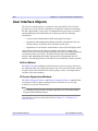
What are iTools? .............................................................................................................
What is the iTools Component Framework? ...................................................................
About this Manual ...........................................................................................................
About the iTools Code Base ............................................................................................
Skills Required to Use the iTools Component Framework .............................................
10
11
12
13
15
Part I: Understanding the iTools Component Framework
Chapter 2
iTool System Architecture .................................................................... 19
Overview of the iTool System Architecture ....................................................................
iTools Object Model Diagram .........................................................................................
iTool Object Identifiers ...................................................................................................
iTool Object Hierarchy ....................................................................................................
iTool Developer’s Guide
20
21
28
31
3
4
Registering Components .................................................................................................. 38
iTool Messaging System .................................................................................................. 41
System Resources ............................................................................................................ 44
Chapter 3
Data Management ................................................................................. 51
Overview of iTool Data Management ............................................................................. 52
iTool Data Manager ......................................................................................................... 53
iTool Data Types .............................................................................................................. 54
iTool Data Objects ........................................................................................................... 56
Predefined iTool Data Classes ......................................................................................... 58
Parameters ........................................................................................................................ 61
Data Type Matching ........................................................................................................ 63
Data Update Mechanism .................................................................................................. 65
Chapter 4
Property Management .......................................................................... 67
About the Properties Interface ......................................................................................... 68
Property Data Types ........................................................................................................ 71
Registering Properties ...................................................................................................... 74
Property Identifiers .......................................................................................................... 77
Property Attributes ........................................................................................................... 78
Property Aggregation ....................................................................................................... 81
Property Update Mechanism ............................................................................................ 84
Properties of the iTools System ....................................................................................... 85
Part II: Using the iTools Component Framework
Chapter 5
Creating an iTool ................................................................................... 89
Overview of iTool Creation ............................................................................................. 90
Creating a New iTool Class ............................................................................................. 91
Registering a New Tool Class ........................................................................................ 101
Creating an iTool Launch Routine ................................................................................. 103
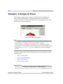
Example: Simple iTool .................................................................................................. 108
Contents
iTool Developer’s Guide
5
Chapter 6
Creating a Visualization ...................................................................... 113
Overview of iTool Visualization Types ........................................................................
Predefined iTool Visualization Classes .........................................................................
Creating a New Visualization Type ..............................................................................
Registering a Visualization Type ..................................................................................
Unregistering a Visualization Type ...............................................................................
Example: Image-Contour Visualization ........................................................................
114
115
121
136
138
140
Chapter 7
Creating an Operation ........................................................................ 145
Overview of Creating an iTool Operation .....................................................................
Predefined iTool Operations .........................................................................................
Operations and the Undo/Redo System .........................................................................
Creating a New Data-Centric Operation .......................................................................
Creating a New Generalized Operation .........................................................................
Operations and Macros ..................................................................................................
Registering an Operation ...............................................................................................
Unregistering an Operation ...........................................................................................
Example: Data Resample Operation .............................................................................
146
148
150
152
165
181
182
184
186
Chapter 8
Creating a Manipulator ....................................................................... 193
Overview of iTool Manipulators ...................................................................................
The Manipulator Creation Process ................................................................................
Predefined iTool Manipulators ......................................................................................
Manipulators and the Undo/Redo System .....................................................................
Using Manipulator Public Instance Data .......................................................................
Creating a New Manipulator .........................................................................................
Registering a Manipulator .............................................................................................
Unregistering a Manipulator .........................................................................................
Example: Color Table Manipulator ...............................................................................
194
197
198
202
204
206
223
225
226
Chapter 9
Creating a File Reader ........................................................................ 229
Overview of iTool File Readers .................................................................................... 230
Predefined iTool File Readers ....................................................................................... 231
iTool Developer’s Guide
Contents
6
Creating a New File Reader ........................................................................................... 234
Registering a File Reader ............................................................................................... 245
Unregistering a File Reader ........................................................................................... 246
Example: TIFF File Reader ........................................................................................... 248
Chapter 10
Creating a File Writer ......................................................................... 253
Overview of iTool File Writers ...................................................................................... 254
Predefined iTool File Writers ........................................................................................ 255
Creating a New File Writer ............................................................................................ 258
Registering a File Writer ................................................................................................ 269
Unregistering a File Writer ............................................................................................ 270
Example: TIFF File Writer ............................................................................................ 272
Part III: Modifying the iTool User Interface
Chapter 11
iTool User Interface Architecture ...................................................... 279
Overview of iTool Interface Architecture ...................................................................... 280
User Interface Objects .................................................................................................... 282
Chapter 12
Using iTool User Interface Elements ................................................ 285
The iTools Feedback Mechanism .................................................................................. 286
Status Messages ............................................................................................................. 287
Prompts .......................................................................................................................... 289
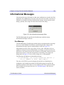
Informational Messages ................................................................................................. 291
Chapter 13
Creating a User Interface Service ..................................................... 293
Overview of the iTool UI Service .................................................................................. 294
Predefined iTool UI Services ......................................................................................... 295
Creating a New UI Service ............................................................................................ 297
Registering a UI Service ................................................................................................ 302
Executing a User Interface Service ................................................................................ 304
Example: Changing a Property Value ............................................................................ 305
Contents
iTool Developer’s Guide
7
Chapter 14
Creating a User Interface Panel ......................................................... 311
Overview of the iTool UI Panel ....................................................................................
Creating a UI Panel Interface ........................................................................................
Creating Callback Routines ...........................................................................................
Registering a UI Panel ...................................................................................................
Example: A Simple UI Panel ........................................................................................
312
313
318
320
322
Chapter 15
Creating a Custom iTool Widget Interface ........................................ 331
About Custom iTool Widget Interfaces ........................................................................
Overview of Creating an iTool Interface ......................................................................
iTool Widget Interface Concepts ..................................................................................
Creating the Interface Routine ......................................................................................
Adding Menus ...............................................................................................................
Adding a Toolbar ...........................................................................................................
Adding an iTool Window ..............................................................................................
Adding a Status Bar .......................................................................................................
Adding a User Interface Panel .......................................................................................
Handling Callbacks .......................................................................................................
Handling Resize Events .................................................................................................
Handling Shutdown Events ...........................................................................................
Creating an iTool Launch Routine ................................................................................
Example: a Custom iTool Interface ...............................................................................
332
335
338
340
344
346
348
350
351
352
354
356
358
360
Appendix A
Controlling iTools from the IDL Command Line ............................... 379
Overview of iTool Programmatic Control ....................................................................
Retrieving an iTool Object Reference ...........................................................................
Retrieving Component Identifiers .................................................................................
Retrieving Property Information ...................................................................................
Changing Property Values .............................................................................................
Running Operations .......................................................................................................
Selecting Items in the iTool ...........................................................................................
Replacing Data in an iTool ............................................................................................
iTool Developer’s Guide
380
381
382
385
389
391
393
394
Contents
8
Appendix B
iTool Compound Widgets .................................................................. 397
Overview of iTools Compound Widgets ....................................................................... 398
CW_ITMENU ................................................................................................................ 399
CW_ITPANEL .............................................................................................................. 404
CW_ITSTATUSBAR .................................................................................................... 408
CW_ITTOOLBAR ........................................................................................................ 411
CW_ITWINDOW .......................................................................................................... 416
Index .................................................................................................... 419
Contents
iTool Developer’s Guide
Chapter 1
Overview of iTools
This chapter provides an overview of the IDL iTool Component Framework.
What are iTools? . . . . . . . . . . . . . . . . . . . . . 10
What is the iTools Component Framework? 11
About this Manual . . . . . . . . . . . . . . . . . . . . 12
iTool Developer’s Guide
About the iTools Code Base . . . . . . . . . . . . 13
Skills Required to Use the iTools Component
Framework . . . . . . . . . . . . . . . . . . . . . . . . . 15
9
10
Chapter 1: Overview of iTools
What are iTools?
IDL Intelligent Tools, or iTools, are applications written in IDL to perform a variety
of data analysis and visualization tasks. iTools share a common underlying
application framework, presenting a full-featured, customizable, application-like user
interface with menus, toolbars, and other graphical features. Several predefined
iTools are provided along with IDL; you can use these tools to explore and visualize
your data without writing any new code yourself. For information on using the
standard iTools provided with IDL, see the iTool User’s Guide.
But iTools are more than just a set of pre-written IDL programs. Behind the iTool
system lies the IDL Intelligent Tools Component Framework — a set of object class
files and associated utilities designed to allow you to easily extend the supplied
toolset or create entirely new tools of your own. This manual will help you
understand the iTools Component Framework so that you can customize existing
iTools or create entirely new ones.
What are iTools?
iTool Developer’s Guide
Chapter 1: Overview of iTools
11
What is the iTools Component Framework?
The iTools component framework is a set of object class definitions written in the
IDL language. It is designed to facilitate the development of sophisticated
visualization tools by providing a set of pre-built components that provide standard
features including:
•
creation of visualization graphics
•
mouse manipulations of visualization graphics
•
annotations
•
management of visualization and application properties
•
undo/redo capabilities
•
data import and export
•
printing
•
data filtering and manipulation
•
interface element event handling
In addition, the iTools component framework makes it easy to extend the system with
components of your own creation, allowing you to design a tool to manipulate and
display your data in any way you choose.
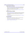
Advantages of Using the Framework
If you are accustomed to creating user interfaces for your IDL applications using IDL
widgets, using the iTools component framework will shorten your development time
by providing much of the application interface via the standard component building
blocks. In many cases, you are freed entirely from the need to create your own
interface elements, handle widget events, and manage the display of data. Even when
your application calls for additional user interface elements, the framework
eliminates the need for you to manually create those elements that your application
has in common with the standard iTool interface.
If you are accustomed to using IDL object graphics in your applications, the iTools
component framework provides a streamlined way of working with the object
graphics hierarchy. Many tasks, such as management of object properties and
manipulation of the object model, are handled automatically.
iTool Developer’s Guide
What is the iTools Component Framework?
12
Chapter 1: Overview of iTools
About this Manual
The iTool Developer’s Guide describes the IDL iTools component framework and
provides examples of its use. After reading this manual, you will understand how to
use the component framework to create your own intelligent tools.
This manual is divided into three parts:
Part I: Understanding the iTools Component Framework
This section describes the iTools component framework in conceptual terms, and
outlines some of the processes you will use in creating new tools using the
framework. While an understanding of the topics in this section may be beneficial as
you develop your own applications, a complete understanding of the way the
framework operates is not required to begin building your own tools.
Part II: Using the iTools Component Framework
This section walks you through the process of creating a new iTool application, either
by extending an existing iTool or by building a new tool from scratch.
Part III: Modifying the iTool User Interface
This section discusses the process of adding your own interface elements to an iTool
application.
What this Manual is Not
This manual is not an API reference for the iTools object classes. Reference
documentation for the iTool classes, methods, and properties is located in the IDL
Reference Guide.
This manual is not a complete description of the object classes that constitute the
iTools component framework. We describe the object classes you will use to create
new iTools, but not necessarily the building blocks from which those classes are
constructed. If you desire a deeper understanding of how the component framework
functions than this manual provides, you can inspect the object class definition files,
which are provided in IDL .pro source code format in the itools/framework
subdirectory of your IDL lib directory.
See “Documented vs. Undocumented Classes” on page 13 for a complete explanation
of our approach to documenting the iTool component framework.
About this Manual
iTool Developer’s Guide
Chapter 1: Overview of iTools
13
About the iTools Code Base
The iTools component framework is written almost entirely in the IDL language. The
IDL code that implements both the component framework and all of the standard
iTools included with IDL is available for you to inspect, copy, and learn from.
To inspect the iTools code, look in the lib/itools subdirectory of your IDL
installation directory. The iTools code base is organized as follows:
•
In the lib/itools directory you will find code that implements the iTool
launch routines. These routines can be called directly at the IDL command line
to launch a specific iTool.
•
In the lib/itools/framework directory you will find the core iTool object
class definitions and utility routines. The classes in this directory define how
the iTools operate; they are made available for your inspection, but they should
not be altered.
•
In the lib/itools/components directory you will find derived iTool object
classes. The classes in this directory implement the non-core features of the
iTool toolset as included with IDL. You are encouraged to use these classes to
implement your own iTool functionality, either by subclassing from a derived
iTool object class or by modifying a copy of the class definition for a derived
class.
•
In the lib/itools/ui_widgets directory you will find the IDL code that
creates an iTool user interface using IDL widgets. You may find it useful to
inspect some of these routines if you are creating a side panel or a dialog used
to collect parameter settings for an operation. See Chapter 11, “iTool User
Interface Architecture” for additional information on creating additional user
interfaces for an iTool.
Documented vs. Undocumented Classes
If you inspect the lib/itools directory and its subdirectories, you will notice that
there are many more classes included in the iTools component framework than are
documented in the IDL Reference Guide and in this manual. Our approach to
documenting the iTools code that is included with IDL is as follows:
•
iTool launch routines for iTools included in the IDL distribution are
documented in the IDL Reference Guide. Use of the launch routines for the
pre-built iTools is discussed in the iTool User’s Guide.
iTool Developer’s Guide
About the iTools Code Base
14
Chapter 1: Overview of iTools
•
The core iTool component framework classes used to build individual iTools,
visualization types, operations, etc. are formally documented in the IDL
Reference Guide and discussed in detail in this manual. If an object class,
method, or property is necessary for the construction of a new iTool or
component of an iTool, it is formally documented in the IDL Reference Guide
or in this manual. Core iTool framework classes are located in the
lib/itools/framework subdirectory of the IDL installation directory.
•
Supporting iTool component framework classes — those used to implement
the documented component framework classes — are not formally
documented. As noted previously, the code for these classes is available for
inspection. Supporting iTool framework classes are located in the
lib/itools/framework subdirectory of the IDL installation directory.
•
Derived iTool classes — those used to implement individual iTools and their
features — are not formally documented. These classes are derived from the
formally documented classes, and as such can be understood by referring to the
formal documentation. Derived iTool framework classes are located in the
lib/itools/components subdirectory of the IDL installation directory.
•
iTool user interface routines are not formally documented. These routines use
standard IDL widget programming techniques, and as such can be understood
by referring to the IDL widget documentation. User interface routines are
located in the lib/itools/ui_widgets subdirectory of the IDL installation
directory.
Warning on Using Undocumented Features
While you are encouraged to inspect the iTools code, and to copy or subclass from
derived classes and user interface routines, be aware that classes and routines that are
not formally documented are not guaranteed to remain the same from one release of
IDL to the next. Keep the following points in mind when implementing your own
iTools:
•
ITT Visual Information Solutions will change undocumented supporting
classes as necessary to improve the iTools system.
•
ITT Visual Information Solutions may also change undocumented derived
classes to fix problems or add functionality; in these cases, we will make every
effort to preserve backwards compatibility, but this is not guaranteed.
If you create new iTool classes based only on the formally documented iTool
interfaces, your tools should operate properly with future releases of IDL. If you base
your tools on undocumented derived classes, minor modifications may be necessary
to ensure future compatibility.
About the iTools Code Base
iTool Developer’s Guide
Chapter 1: Overview of iTools
15
Skills Required to Use the iTools Component
Framework
The iTools component framework consists of a set of IDL object classes,
supplemented by utility routines. If you are already familiar with the concepts of
object-oriented programming, or have written programs that use IDL object graphics,
you will find the iTools framework easy to understand and use. The framework
approach means that most of the details of creating a full-featured and usable
application are already taken care of, leaving you free to concentrate on how best to
manipulate and visualize your data.
If you are familiar with procedural programming in IDL but new to object-oriented
programming, you will find developing iTools to be a gentle introduction to the topic.
The iTools framework has been designed to allow IDL users with little or no
experience writing object-oriented programs to easily customize and extend the basic
iTool applications. While some familiarity with the concepts of object-oriented
programming is necessary to successfully develop iTools, you should be able to
create simple modifications of existing tools almost immediately, and more complex
customizations soon thereafter.
iTool Developer’s Guide
Skills Required to Use the iTools Component Framework
16
Skills Required to Use the iTools Component Framework
Chapter 1: Overview of iTools
iTool Developer’s Guide
Part I: Understanding
the iTools Component
Framework
Chapter 2
iTool System
Architecture
This chapter describes the iTool component framework architecture.
Overview of the iTool System Architecture
iTools Object Model Diagram . . . . . . . . . . .
iTool Object Identifiers . . . . . . . . . . . . . . . .
iTool Object Hierarchy . . . . . . . . . . . . . . . .
iTool Developer’s Guide
20
21
28
31
Registering Components . . . . . . . . . . . . . . 38
iTool Messaging System . . . . . . . . . . . . . . 41
System Resources . . . . . . . . . . . . . . . . . . . . 44
19
20
Chapter 2: iTool System Architecture
Overview of the iTool System Architecture
The iTool system architecture is designed to maintain a separation between the
functionality provided by an iTool and the graphical presentation layer that reveals
that functionality to an iTool user (the iTool user interface). Such a separation allows
for the creation of different user interfaces for the same underlying functionality;
while the initial iTool user interface has been created using IDL widgets, it is easy to
imagine using other technologies to create an interface to the underlying iTool
functionality.
To support the goal of enabling different user interfaces for a given set of iTool
functionality, the iTool architecture includes the following features:
•
A design in which a single iTool object (based on the IDLitTool class) contains
all non-interactive tool functionality. Similarly, a single iTool object (based on
the IDLitUI class) contains all user interface functionality. This division is
clearly visible in the “iTools Object Model Diagram” on page 21.
•
An object identifier system that provides a platform-neutral way to identify
objects across process and machine boundaries. Additionally, the object
identifier system is designed to work with existing component technologies
such as COM and Java.
•
A minimal connection between the non-interactive tool functionality and the
presentation layer. The tool architecture provides a small set of highly abstract
methods that the tool and presentation layer use to communicate with each
other. This minimal connection means that the presentation layer needs only a
single object reference to the iTool object itself.
•
A messaging system that allows one component to observe another, receiving
notification messages when the observed component changes in some way.
This chapter describes some of the core ideas of the iTool system: component
inheritance, object identifiers, the iTool system object and the object hierarchy it
contains, the concept of registration, and how information is passed between iTool
components.
Overview of the iTool System Architecture
iTool Developer’s Guide
iTool Developer’s Guide
Figure 2-1: iTools Object Model Hierarchy
The following figure shows inheritance among the iTools component object classes that define the base
functionality of all iTools. The diagram is intended to provide a visual overview of the structure of the iTools,
and to provide a quick indication of the methods and properties available to objects of a given class. See the
IDL Reference Guide for details regarding the available properties and methods of these components.
iTools Object Model Diagram
Chapter 2: iTool System Architecture
21
iTools Object Model Diagram
22
Chapter 2: iTool System Architecture
Every iTool is constructed using the hierarchy of predefined and documented object
classes shown in the previous figure. Each of these predefined (as opposed to userdefined) object classes are available to use or customize in your iTool application.
However, there is no need to create and instantiate the entire hierarchy when creating
a custom iTool object.
Launching an iTool application creates instances of objects in the iTools class
hierarchy, as well as others subclassed from the predefined classes. Developing an
application that subclasses from the IDLitToolBase class automatically includes the
functionality of parent object classes, such as IDLitTool, and IDLitIMessaging. This
will also include and register manipulator and operation objects that are common
among the predefined iTools. Unwanted items can be unregistered. Other predefined
objects are instantiated as needed. For example, an iTool application may be started
without a data argument. Only when data is imported into the tool is a predefined or
custom IDLitVisualization object created to contain the data. For instance, an
IDLitVisPlot object is instantiated when data is imported into the iPlot tool, which
may or may not be when the tool is initiated.
Once the hierarchy of component objects have been instantiated, there is no need to
maintain a long list of object references to access and manipulate individual objects.
Each component is assigned an identifier when it is instantiated; an identifier is a
simple string that can be used to access an object (such as an IDLItVisPlot object) in
order to change properties, apply operations, or make other modifications. See “iTool
Object Identifiers” on page 28 for details.
The following sections further describe the chain of inheritance followed by the
objects that make up a particular iTool. The classes listed below are subclassed from
the iTool object classes shown in the “iTools Object Model Diagram” on page 21.
With the exception of the atomic graphic objects (listed in “Atomic Graphic Objects”
on page 26), these subclasses are not documented and are subject to change. While
we encourage you to inspect these undocumented subclasses and use them as
examples when creating your own subclasses, we discourage you from subclassing
from them directly.
Note
ITT Visual Information Solutions may add, change, or remove undocumented
subclasses of the documented iTools classes at any time. The following lists may
not exactly match the set of subclasses shipped with any particular version of IDL.
Except for the atomic graphic objects, all of the classes listed below are written in the
IDL language. Their definitions can be found in the lib/itools/components
subdirectory of your IDL installation. See “About the iTools Code Base” on page 13
iTools Object Model Diagram
iTool Developer’s Guide
Chapter 2: iTool System Architecture
23
for additional information about iTools code and the differences between documented
and undocumented classes.
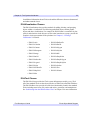
IDLitVisualization Classes
The IDLitVisualization class provides methods for adding, deleting, and grouping
objects within a visualization. The following predefined classes contain graphic
objects and other visualizations. For example, the IDLitVisPlot is a container for plot,
symbol, and selection visual objects as well as other items that as a group, provide the
complete visual representation of the plot data. See Chapter 6, “Creating a
Visualization” for details.
• IDLitVisAxis
• IDLitVisPlotProfile
• IDLitVisColorbar
• IDLitVisPlot3D
• IDLitVisContour
• IDLitVisPolygon
• IDLitVisHistogram
• IDLitVisPolyline
• IDLitVisImage
• IDLitVisROI
• IDLitVisIntVol
• IDLitVisShapePoint
• IDLitVisIsoSurface
• IDLitVisShapePolygon
• IDLitVisLegend
• IDLitVisShapePolyline
• IDLitVisLight
• IDLitVisSurface
• IDLitVisLineProfile
• IDLitVisText
• IDLitVisMapGrid
• IDLitVisVolume
• IDLitVisPlot
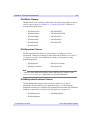
IDLitTool Classes
The IDLitTool class provides the iTools system infrastructure used by every iTool.
All of the standard iTools are based on a subclass of IDLitTool called IDLitToolbase.
The IDLitToolbase class provides all of the base functionality found in the standard
iTools including menu items, file readers and writers, operations, and manipulators.
See “Subclassing from the IDLitToolbase Class” in Chapter 5 for more information
iTool Developer’s Guide
iTools Object Model Diagram
24
Chapter 2: iTool System Architecture
on included functionality. See the iTool User’s Guide for information on using
individual iTools.
• IDLitToolContour (iContour tool)
• IDLitToolSurface (iSurface tool)
• IDLitToolImage (iImage tool)
• IDLitToolVolume (iVolume tool)
• IDLitToolMap (iMap tool)
• IDLitToolVector (iVector tool)
• IDLitToolPlot (iPlot tool)
IDLitData Classes
The IDLitData class stores core IDL data types, gets and sets data, and receives
updates regarding data changes. The predefined IDLitData classes listed in the
following table are designed to hold data which can then be displayed in an iTool.
See Chapter 3, “Data Management” for details.
• IDLitDataIDLArray2D
• IDLitDataIDLPalette
• IDLitDataIDLArray3D
• IDLitDataIDLPolyVertex
• IDLitDataIDLImage
• IDLitDataIDLVector
• IDLitDataIDLImagePixels
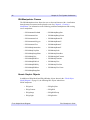
IDLitReader Classes
The IDLitReader class contains predefined file readers that determine the type of data
being accessed, and create an IDLitData object to contain the data. See Chapter 9,
“Creating a File Reader” for details on creating and using file readers.
• IDLitReadASCII
• IDLitReadJPEG2000
• IDLitReadBinary
• IDLitReadPICT
• IDLitReadBMP
• IDLitReadPNG
• IDLitReadDICOM
• IDLitReadShapefile
• IDLitReadISV
• IDLitReadTIFF
• IDLitReadJPEG
• IDLitReadWAV
iTools Object Model Diagram
iTool Developer’s Guide
Chapter 2: iTool System Architecture
25
IDLitWriter Classes
The IDLitWriter class contains predefined file writers that export graphics or data to
a file of a specified type. See Chapter 10, “Creating a File Writer” for details on
creating and using file writers.
• IDLitWriteASCII
• IDLitWriteJPEG
• IDLitWriteBinary
• IDLitWriteJPEG2000
• IDLitWriteBMP
• IDLitWritePICT
• IDLitWriteEMF
• IDLitWritePNG
• IDLitWriteEPS
• IDLitWriteTIFF
• IDLitWriteISV
IDLitOperation Classes
The IDLitOperation class defines an action on data, or a change to an iTool
visualization. Transaction recording provides undo/redo capabilities. See Chapter 7,
“Creating an Operation” for information on creating a new operation or using
predefined operations.
• IDLitOpBytscl
• IDLitOpCurveFitting
• IDLitOpConvolution
• IDLitOpSmooth
Note
There are many additional operations (named with the prefix “idlitop”) in the
lib\itools\components subdirectory of your IDL installation.
IDLitManipulatorContainer Classes
The IDLitManipulatorContainer class provides a container for a group of
manipulators, among which an active manipulator may be set. The following
manipulator containers are predefined. The manipulators held within each predefined
container are described in “Predefined iTool Manipulators” on page 198.
• IDLitManipArrow
• IDLitManipRotate
• IDLitManipRange
iTool Developer’s Guide
iTools Object Model Diagram
26
Chapter 2: iTool System Architecture
IDLitManipulator Classes
The IDLitManipulator class allows the user to select and interact with a visualization
through mouse movements and keyboard events. See Chapter 8, “Creating a
Manipulator” for information on the following predefined manipulators and creating
a new manipulator.
• IDLitAnnotateFreehand
• IDLitManipRangePan
• IDLitAnnotateLine
• IDLitManipRangeZoom
• IDLitAnnotateOval
• IDLitManipRotate3D
• IDLitAnnotatePolygon
• IDLitManipRotateX
• IDLitAnnotateText
• IDLitManipRotateY
• IDLitManipAnnotation
• IDLitManipRotateZ
• IDLitManipCropBox
• IDLitManipScale
• IDLitManipImagePlane
• IDLitManipSelectBox
• IDLitManipLine
• IDLitManipSurfContour
• IDLitManipROIFree
• IDLitManipTranslate
• IDLitManipROIOval
• IDLitManipView
• IDLitManipROIPoly
• IDLitManipViewPan
• IDLitManipROIRect
• IDLitManipViewZoom
• IDLitManipRangeBox
Atomic Graphic Objects
In addition to IDLgrModel and IDLgrWindow objects shown in the “iTools Object
Model Diagram” on page 21, the following IDL objects inherit from
IDLitComponent:
• IDLgrAxis
• IDLgrPolyline
• IDLgrContour
• IDLgrROI
• IDLgrImage
• IDLgrROIGroup
• IDLgrLight
• IDLgrSurface
iTools Object Model Diagram
iTool Developer’s Guide
Chapter 2: iTool System Architecture
27
• IDLgrPlot
• IDLgrText
• IDLgrPolygon
• IDLgrVolume
iTool Developer’s Guide
iTools Object Model Diagram
28
Chapter 2: iTool System Architecture
iTool Object Identifiers
iTool object identifiers are simple strings that uniquely identify individual objects
within the hierarchy of iTool objects in much the same way that a computer file
system identifies files within a hierarchy of files. The object hierarchy (and, by
extension, the object identifiers) also describe where information about objects is
made visible in the iTool user interface; see “iTool Object Hierarchy” on page 31 for
additional discussion of the iTool hierarchy and the iTool system object.
Besides providing a familiar, user-readable way to identify objects in the iTool
system, object identifiers also allow iTool developers to refer to an object without
having to maintain an actual object reference to that object. This ability to use a
lightweight string object to refer to a potentially “heavy” object in the iTool system
makes it possible to maintain a very loose coupling between the objects that
implement an iTool’s functionality and those that implement its user interface. This
allows for object access that can cross process and machine boundaries, paving the
way for the use of the iTool system in more distributed environments.
Note
Object identifiers are not to be confused with object descriptors. See “Object
Descriptors” on page 30 for details.
Object identifier strings are assigned when an object class is registered with either an
individual iTool or with the iTool system object. See “Registering Components” on
page 38 for a discussion of the registration process.
Fully-Qualified vs. Relative Identifiers
Identifiers can either be fully qualified, meaning that they depict the entire path from
the root iTool system object to the object being identified, or relative, meaning they
depict the path from the root of the current iTool. Fully qualified identifiers begin
with the “/” character, and refer to objects that are accessible to all iTools that become
active during the lifetime of the iTool system object. Relative identifiers do not begin
with a “/” and refer to objects that are accessible only within a specified container
object.
For example, the identifier string
/DATA MANAGER/MY DATA
refers to an object named MY DATA, located in the system-level DATA MANAGER
container. Because the identifier is fully qualified, the MY DATA object is visible to
any iTool that is active during the iTool session.
iTool Object Identifiers
iTool Developer’s Guide
Chapter 2: iTool System Architecture
29
Similarly, the identifier string
OPERATIONS/FILTERS/MY FILTER
refers to an object named MY FILTER, located in a sub-container of the iTool-level
OPERATIONS container named FILTERS. Because the identifier is relative, the
MY FILTER object is visible only to the current iTool.
Note
Object identifiers are stored as upper-case strings. Spaces are allowed.
Using Identifiers
Numerous methods defined by iTools object classes accept object identifiers as
arguments to uniquely identify an object instance. This frees you as a developer from
the need to obtain and keep track of an actual object reference for each object you
wish to refer to or modify.
For example, the DoSetProperty method of the IDLitTool object class allows you to
change the value of an object property by supplying the identifier for the object
whose property is to be changed, as well as the identifier for the property itself.
Similarly, the DoAction method of the IDLitTool class allows you to initiate an
operation simply by supplying its identifier.
Retrieving Identifiers
At times, you may know the identifier of the object you wish to affect. This is the
case when your own code registers an operation, for example; you must supply the
identifier when calling the ITREGISTER routine or Register method. (See
“Registering Components” on page 38 for additional details.)
Other times, you may not know the identifier of the object you wish to affect. In these
cases, you have two options:
1. If your code has access to the actual object reference to the object whose
identifier you need, you can use the GetFullIdentifier method of the
IDLitComponent object class. See “IDLitComponent::GetFullIdentifier” (IDL
Reference Guide) for details.
2. If your code does not have access to an object reference, you can use the
FindIdentifiers method of the IDLitTool object class to retrieve a list of
identifiers that match a specified pattern. See “IDLitTool::FindIdentifiers”
(IDL Reference Guide) for details.
iTool Developer’s Guide
iTool Object Identifiers
30
Chapter 2: iTool System Architecture
Proxy Identifiers
Because the location of an object in the iTool object hierarchy corresponds to the
place that object is made visible to iTool users, you may at times want an object to be
located in multiple places in the iTool object hierarchy. For example, the Undo
operation appears in two places in the standard iTool user interface: under the Edit
menu and on the toolbar. Rather than duplicating the Undo operation object in each
of those places in the iTool object hierarchy, we can use a proxy mechanism to
register the same object instance with multiple object identifiers. In the case of the
Undo operation, the operation itself is located in the EDIT subcontainer of the iTool’s
OPERATIONS container, which implies that the operation appears under the iTool’s
Edit menu. A proxy (or alias) to this object is created in the EDIT subcontainer of the
iTool’s TOOLBAR container, which places the operation on the toolbar. Only one
instance of the Undo object is created, but its action can be invoked from both the
menu and the toolbar.
Proxy identifiers are assigned by the Register method for the object being proxied.
See “Registering Components” on page 38 for additional details.
Object Descriptors
Object descriptors are iTool objects that contain enough information about a given
object class to create an object of that class when necessary. In many cases, object
descriptors, rather than instances of the objects they create, are stored in the iTool
hierarchy; this approach allows object instances to be created only when needed.
Object descriptors also manage instances of objects that can be re-used by the system,
avoiding the need to create a new instance of an object (such as an operation) each
time it is used.
Cases in which an iTool developer will need to know about or use object descriptors
rather than object identifiers are very rare. We mention object descriptors here
because they are used extensively in the iTool object hierarchy to expose the
functionality of objects that are created as needed, rather than being created
automatically when the iTool is created.
iTool Object Identifiers
iTool Developer’s Guide
Chapter 2: iTool System Architecture
31
iTool Object Hierarchy
The iTool system is a collection of object class instances organized in a hierarchy of
container objects. The hierarchy serves both to organize the numerous object
instances and to display information about the objects in the iTool user interface. In
most cases, an object’s location in the iTool hierarchy controls where and how the
object is made visible in the user interface.
For example, the Rotate operation object is stored in the iImage iTool’s object
hierarchy with the object identifier
OPERATIONS/OPERATIONS/ROTATE
From this identifier we can deduce two things:
1. The Rotate operation object is stored in the iTool’s object hierarchy in the
OPERATIONS container within the OPERATIONS container.
2. The Rotate operation will be displayed in the iTool’s widget interface under
the Operations menu.
iTool System Object
The iTool system object contains and provides a single point of access to all objects
managed by the iTool system. Only one instance of the iTool system object can exist
in a given IDL session; it is created automatically when any iTool is created.
Note
As an iTool developer, there is no need for you to create or otherwise interact with
the system object yourself. This discussion of the structure of the system object is
included solely to help you understand the organization of iTool objects.
The iTool system object is a subclass of the IDLitContainer object, which provides
functionality to manage a hierarchy of container objects via their object identifiers.
iTool System-Level Hierarchy
As the root of the iTools environment, the iTool system object has the unique object
identifier of “/”. All fully qualified object identifiers begin with this reference to the
system object, providing a global location on which to base a location in the iTools
hierarchy.
The hierarchy contained by the iTool system object includes the following
containers:
iTool Developer’s Guide
iTool Object Hierarchy
32
Chapter 2: iTool System Architecture
/TOOLS
This container holds references to all active iTools.
/CLIPBOARD
This container holds items that are on the local system clipboard.
/REGISTRY
This container holds object descriptors for the iTool object classes that are registered
with the system object. Individual iTools, Visualization types, and User Interface
types can all be registered with the system object; other iTool object types are
registered only with the individual iTool to which they belong. Objects that are
registered with the system object are available for use in the IDL MAIN execution
context — that is, these objects are available at the IDL command line.
/REGISTRY/TOOLS
This container holds the object descriptors for the individual iTools available in the
system. All iTools must be registered with the system object.
/REGISTRY/VISUALIZATIONS
This container holds the object descriptors for the visualization types registered with
the system object. Visualization types that are registered with the system object are
available to all iTools, and thus allow users to create visualizations via the
OVERPLOT keyword to an iTool launch routine even in cases where the appropriate
visualization type is not registered with the current iTool. Registered visualizations
types are displayed in a list in the iTool Insert Visualization dialog. See Chapter 6,
“Creating a Visualization” for more on visualization types.
/REGISTRY/WIDGET INTERFACE
This container holds a list of available user interface routines that are available to the
system. In the initial release of the iTool system, only one user interface exists. By
providing the capability to choose from a list of interfaces, however, different
interfaces can easily be “plugged in” to the iTool framework in the future.
/DATA MANAGER
This container holds the data objects that have been imported into or created by the
iTool system. Since the data manager container is system-scoped, all data in the
system is available to all iTools.
iTool Object Hierarchy
iTool Developer’s Guide
Chapter 2: iTool System Architecture
33
iTool Objects
Individual iTool tool objects contain all objects that are directly associated with a
particular instance of a particular iTool. Any number of tool objects can exist; their
unique identifiers are found in the /TOOLS container of the iTools system object.
As an iTool developer, you will use both the tool’s object reference and its object
identifier inside your code.
If you are using command-line style procedures and functions to control an existing
iTool from non-iTools code, you can retrieve the tool object identifier and object
reference using the ITGETCURRENT routine.
iTool-Level Hierarchy
Each individual iTool (held in the /TOOLS container of the system object) has a subhierarchy of tool-level containers. For example, every iTool has a container named
OPERATIONS containing objects that affect data. An operation named MyOperation
registered for an iTool named MyTool has two possible object identifiers:
/TOOLS/MYTOOL/OPERATIONS/MYOPERATION
and
OPERATIONS/MYOPERATION
The first identifier is fully qualified; the second is relative to the MyTool object.
The object identifier hierarchy of each individual iTool includes the following
containers:
FILE READERS
FILE WRITERS
MANIPULATORS
OPERATIONS
TOOLBARS
WINDOW
WINDOW/VIEW
WINDOW/VIEW/VISUALIZATION LAYER
WINDOW/VIEW/VISUALIZATION LAYER/DATA SPACE
WINDOW/VIEW/VISUALIZATION LAYER/DATA SPACE/VISUALIZATION
WINDOW/VIEW/ANNOTATION LAYER
WINDOW/VIEW/ANNOTATION LAYER/ANNOTATION
FILE READERS
A file reader is an iTool component object that contains the information necessary to
open a file and read its data into the iTools data manager. The FILE READERS
container holds the object descriptors of file readers registered with the individual
iTool Developer’s Guide
iTool Object Hierarchy
34
Chapter 2: iTool System Architecture
iTool. Default properties of file readers can be set interactively via the System
Preferences dialog. See Chapter 9, “Creating a File Reader” for more on file readers.
For example, the relative identifier for the ASCII file reader is:
FILE READERS/ASCII TEXT
FILE WRITERS
A file writer is an iTool component object that contains the information necessary to
create a file from data stored in the iTools data manager. The FILE WRITERS
container holds the object descriptors of file writers registered with the individual
iTool. Default properties of file writers can be set interactively via the System
Preferences dialog. See Chapter 10, “Creating a File Writer” for more on file writers.
For example, the relative identifier for the Windows Bitmap file writer is:
FILE WRITERS/WINDOWS BITMAP
MANIPULATORS
A manipulator is an iTool component object that performs some action on a
visualization selected in an iTool. The MANIPULATORS container holds the object
descriptors of manipulators registered with the individual iTool. See Chapter 8,
“Creating a Manipulator” for more on manipulators.
For example, the relative identifier for the Rotate manipulator is:
MANIPULATORS/ROTATE
OPERATIONS
An operation is a set of IDL procedure, function, and method calls that acts on either
a data item or on the iTool itself. The OPERATIONS container holds the object
descriptors of operations registered with the individual iTool. Registered operations
appear in the Operations menu of the iTool. See Chapter 7, “Creating an Operation”
for more on operations.
The object identifier hierarchy rooted at OPERATIONS is displayed in the iTools
Operations Browser in a tree view. The hierarchy may contain multiple levels; the
levels are used to organize the individual operations in the iTools Operations menu
and in the Operations Browser. For example, the relative identifier of the File Open
operation is:
OPERATIONS/FILE/OPEN
Note that operations that appear in the iTool Operations menu repeat the identifier
OPERATIONS. The first instance specifies that the object is stored in the Operations
iTool Object Hierarchy
iTool Developer’s Guide
Chapter 2: iTool System Architecture
35
container, the second specifies that it appears in the Operations menu. For example,
the relative identifier for the Statistics operation is:
OPERATIONS/OPERATIONS/STATISTICS
TOOLBAR
A toolbar is an iTool component object that contains information about buttons that
should be displayed in the iTool’s main interface. The TOOLBAR container holds
the object descriptors of operations, manipulators, and annotations that are exposed
via the iTool’s toolbar. In most cases, these objects are proxies of objects held in
other containers. For example, the File Open operation is held by the FILE
subcontainer of the OPERATIONS container; it is also exposed (via a proxy) on the
iTool toolbar as:
TOOLBAR/FILE/OPEN
WINDOW
A window is an iTool component that holds (indirectly) the actual graphics object
hierarchy displayed in the iTool window. It is a representation of an on-screen area
on a display device that serves as a graphics destination. Each window contains one
or more views. The relative identifier of a window is always:
WINDOW
The object hierarchy rooted at the WINDOW is displayed in the iTools Visualization
Browser in a tree view. The objects in the hierarchy correspond to the levels shown in
the Visualization Browser view.
VIEW
A view is an iTool component that represents a rectangular area in which graphics
objects are drawn. Each view contains one or more visualization layers and one or
more annotation layers. For example the relative identifier of the first view in a
window container is:
WINDOW/VIEW_1
VISUALIZATION LAYER
A visualization layer is an iTool component that contains visualizations. Each
visualization layer contains zero or more data spaces. For example, the relative
identifier of the visualization layer in the first view in window container is:
WINDOW/VIEW_1/VISUALIZATION LAYER
iTool Developer’s Guide
iTool Object Hierarchy
36
Chapter 2: iTool System Architecture
DATA SPACE
A data space is an iTool component that manages the data range, transformation
matrix, and other data-centric properties of visualizations in a visualization layer.
Each data space contains one or more visualizations. For example, the relative
identifier of the second data space in the visualization layer in the first view in
window container is:
WINDOW/VIEW_1/VISUALIZATION LAYER/DATA SPACE_1
Note
Data space numbering is zero-based — that is, the first data space created is number
zero. The object identifier for the first data space, however, does not include the
number. Identifiers for additional data spaces do include the number.
A visualization is a group of component objects that are displayed to the iTool user in
the main iTool window. Examples of visualizations are plots, surfaces, contours, etc.
For example, the relative identifier of the first plot visualization in the first data space
in the visualization layer in the first view in window container is:
WINDOW/VIEW_1/VISUALIZATION LAYER/DATA SPACE/PLOT
Note
Visualization numbering is zero-based — that is, the first visualization of a specific
type created within a data space is number zero. The object identifier for the first
visualization, however, does not include the number. Identifiers for additional
visualizations of the same type within the same data space do include the number.
Visualizations may be containers themselves, containing other visualizations. The
Axis visualization is an example; it contains all of the individual axes inserted into a
given data space.
ANNOTATION LAYER
An annotation layer is an iTool component that contains annotations. Each
visualization layer contains zero or more annotations. For example, the relative
identifier of the annotation layer in the first view in window container is:
WINDOW/VIEW_1/ANNOTATION LAYER
An annotation is a graphical component that can be added to the main iTool window
by the iTool user in an interactive operation. Examples of annotations are text, lines,
polygons, etc. For example, the relative identifier of the first text annotation in the
first annotation layer in the first view in window container is:
WINDOW/VIEW_1/ANNOTATION LAYER/TEXT
iTool Object Hierarchy
iTool Developer’s Guide
Chapter 2: iTool System Architecture
37
Note
Annotation numbering is zero-based — that is, the first annotation of a specific type
created within a data space is number zero. The object identifier for the first
annotation, however, does not include the number. Identifiers for additional
annotations of the same type within the same data space do include the number.
iTool Developer’s Guide
iTool Object Hierarchy
38
Chapter 2: iTool System Architecture
Registering Components
Registering an object class links the file containing the IDL code that defines the
object (an iTool, a visualization type, an operation, etc.) with the object identifier.
Objects can be registered either with the iTool system object (in which case their
identifiers are fully qualified) or with an individual iTool class (in which case their
identifiers are relative to the iTool or to a specific container within the tool).
When an object is registered, it is not immediately instantiated. Instead, the
information required to create the object is saved in an object descriptor and placed in
the appropriate location in the iTool hierarchy. Later, when the functionality
contained in the object is needed, the object descriptor either instantiates the object or
provides a reference to an existing instance of the object.
Registration Methods
Objects are registered using the ITREGISTER procedure (to register the object with
the iTool system object) or by calling a Register method on an individual iTool
component object.
Registering Objects with the System Object
Individual iTool components can be registered with the iTool system object. Of these:
•
individual iTools must be registered with the system object before they can be
created and displayed.
•
visualization types, annotation types, and file readers and writers may be
registered with the system object, but can also be registered with an iTool.
Components that are registered with the system object will be available to all
iTools.
•
user interface types must be registered with the system object; however,
creation of new user interfaces is a rare and complex occurrence.
To register an object with the iTool system object, use the ITREGISTER procedure.
See “ITREGISTER” (IDL Reference Guide) for details and “Registering a New Tool
Class” on page 101 for an example using ITREGISTER.
Registering Objects with an iTool
Visualization types, operations, manipulators, file readers, and file writers can be
registered with an individual iTool. Of these, all must be registered with an individual
Registering Components
iTool Developer’s Guide
Chapter 2: iTool System Architecture
39
iTool except for visualization types, which may have been registered with the iTool
system object.
Note
Many operations, manipulators, file readers, and file writers are registered by the
IDLitToolbase class. If you create a new iTool based on this class, these features
will be registered automatically. See “Subclassing from the IDLitToolbase Class”
on page 91 for details.
Tip
If you want some, but not all, of the functionality exposed by the IDLitToolbase
class, you may find it useful to subclass from IDLitToolbase and unregister one or
more features. See the sections on unregistering items in the chapters devoted to
creating operations, manipulators, file readers, and file writers.
To register an object with an individual iTool, use one of the Register methods of the
IDLitTool class. Register methods exist for each type of object that can be registered
(IDLitTool::RegisterOperation for operations, for example). A call to a registration
method looks something like this
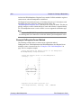
self->RegisterObject, ObjectName, Object_Class_Name
where Object is one of the object types that can be registered (Visualization,
Operation, Manipulator, FileReader, or FileWriter), ObjectName is the string you will
use when referring to the object, and Object_Class_Name is a string that specifies the
name of the class file that contains the object’s definition.
See the Register methods under “IDLitTool” (IDL Reference Guide) for additional
details, and “Registering a Visualization Type” on page 136, “Registering an
Operation” on page 182, “Registering a Manipulator” on page 223, “Registering a
File Reader” on page 245, and “Registering a File Writer” on page 269 for examples.
Specifying Object Identifiers
You can use the IDENTIFIER keyword to any of the Register methods to specify an
object identifier for the registered object, and thus specify the object’s location in the
iTool object hierarchy and in the user interface. If you do not specify a value for the
IDENTIFIER keyword, a suitable object identifier will be constructed based on the
type of object being registered and the specified ObjectName.
Proxy Registration
You can also register an object as a proxy (or alias) to another object that has already
been registered. Registering an object as a proxy places the proxy object in the iTool
iTool Developer’s Guide
Registering Components
40
Chapter 2: iTool System Architecture
hierarchy in the specified place, but actually calls the original object when a user
requests the proxied object. To register a proxy object, specify an object identifier
string as the value of the PROXY keyword to the Register method. For example, the
following call to the RegisterOperation method places a proxy to the Undo object
stored in the iTool hierarchy under OPERATIONS/EDIT/UNDO in the hierarchy under
TOOLBAR/EDIT/UNDO:
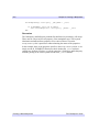
self->RegisterOperation, 'Undo', PROXY = 'Operations/Edit/Undo', $
IDENTIFIER = 'Toolbar/Edit/Undo'
Registering Components
iTool Developer’s Guide
Chapter 2: iTool System Architecture
41
iTool Messaging System
Notifications are messages sent from one iTool component to one or more observer
components. The iTool messaging system provides a unified way for components to
notify each other of important changes; it is quite general, and can be used to send
messages related to any type of change. Some examples:
•
Visualizations send notifications when components of the visualization are
selected or unselected.
•
Notifications are issued when the user changes the value of a property. All
visualizations or operations that depend on the value of that property are
automatically notified.
Note
Messaging functionality is provided mainly by the IDLitTool and IDLitUI objects,
using the interface defined by the IDLitIMessaging object.
In many cases, the iTool messaging system is transparent to you as an iTool
developer; you may never need to create code that uses the messaging system. The
main exception to this rule is the creation of user interface panels (discussed in
Chapter 14, “Creating a User Interface Panel”), but there may be other instances in
which the notifications sent by the iTool framework itself do not meet your needs and
must be augmented by your own message generation and handling code.
Sending Notifications
To send a notification, an iTool component calls the IDLitIMessaging::DoOnNotify
method, providing the object identifier of the component that is sending the
notification, a string that uniquely identifies the message being sent, and any value
associated with the message. The method call looks like:
Obj->DoOnNotify, IdOriginator, IdMessage, Value
where Obj is the object calling the DoOnNotify method, IdOriginator is the iTool
component object identifier string of the component that changed, IdMessage is a
string that uniquely identifies the change, and Value is the value associated with
IdMessage.
The DoOnNotify method is available to most iTool components, since all
components subclass from the IDLitIMessaging class either directly or indirectly.
See “IDLitIMessaging::DoOnNotify” (IDL Reference Guide) for details.
iTool Developer’s Guide
iTool Messaging System
42
Chapter 2: iTool System Architecture
The IdOriginator argument is generally the object identifier of an iTool component
object, but it can be any string value.
Notification Messages
The value of the IdMessage argument to the DoOnNotify method is a string value
that must uniquely identify the message being sent. iTool components and callback
routines that process notification messages use the value of the IdMessage string to
determine what action to take when a message arrives from an observed component.
When you call the DoOnNotify method yourself, use caution in choosing the value of
the IdMessage string. If the string you choose conflicts with a message being sent by
another iTool component, the message-handling routines may be activated at the
wrong time.
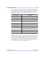
Standard iTool Messages
The following is a list of notification messages sent by components that are part of
the standard iTool distribution:
Message String
SELECTED
UNSELECTED
Meaning
The selection state of an item being watched has
changed. Value contains the object identifier of the
component whose selection changed.
SELECTIONCHANGED The selected item within the current iTool changed.
Value contains an empty string.
ADDITEMS
MOVEITEMS
REMOVEITEMS
SETPROPERTY
A call to the Add, Move, or Remove method of an
IDLitContainer that supports the IDLitIMessaging
interface was made. Value contains the object
identifier of the item that was added, moved, or
removed.
The value of a property has been changed on a
component. If a single property was changed, Value
contains the identifier of the property that changed. If
multiple properties were changed, Value contains a
null string.
Table 2-1: Standard iTool Messages
iTool Messaging System
iTool Developer’s Guide
Chapter 2: iTool System Architecture
Message String
SENSITIVE
UNSENSITIVE
43
Meaning
The SENSITIVE property of a component has
changed. Value contains an empty string.
VIEW_PAN
The currently selected view has been panned. Value is
a two-element integer vector [x, y] specifying the
location of the lower left corner of the visible portion
of the view relative to the lower left corner of the
entire view.
VIEW_ZOOM
The currently selected view has been zoomed. Value
is a floating-point integer representing the new zoom
factor for the view.
Table 2-1: Standard iTool Messages (Continued)
Observers
To watch for notifications from an iTool component, an iTool component calls the
IDLitIMessaging::AddOnNotifyObserver method, providing the object identifier of
the component that is watching and the object identifier of the object being watched
as arguments. The method call looks like:
Obj->AddOnNotifyObserver, IdObserver, IdSubject
where Obj is the object calling the AddOnNotifyObserver method, IdObserver is the
iTool component object identifier string of the component that is watching for
notification messages, and IdSubject is a string value identifying the item that
IdObserver is interested in. This is normally the object identifier of an iTool
component object, but it can be any string value.
Note
When writing a user interface panel, the IdObserver argument contains the object
identifier of a user interface adaptor created by a call to the RegisterWidget method
of the IDLitUI class. See “Creating a UI Panel Interface” on page 313 for details.
iTool Developer’s Guide
iTool Messaging System
44
Chapter 2: iTool System Architecture
System Resources
This section contains information on resources used by the iTool system.
Icon Bitmaps
Some iTool components have associated icons. Icons for iTool components are
displayed in the tree view of a browser window.
Bitmaps used as icons in the iTool system must be either .bmp or .png files. The
images contained in icon bitmap files can be either True Color (24-bit color) images
or paletted (8-bit color) images.
Note
There are different requirements for bitmap images that will be displayed on button
widgets. See “Using Button Widgets” (Chapter 4, Widget Application
Programming) for details.
By default, bitmap files for icons used by the iTool system are stored in the bitmaps
subdirectory of the resource subdirectory of the IDL distribution. If an icon’s
bitmap file is located in this directory, specify the base name of the file — without the
filename extension — as the value of the ICON property of the component. For
example, to use the file arrow.bmp, located in the resource/bitmaps
subdirectory of the IDL distribution, specify the value of the ICON property as
follows:
ICON = 'arrow'
If you include the filename extension when setting the ICON property, the iTool
system assumes that the specified value is the full path to the bitmap file. For
example, to use the file my_icon.png, stored in the directory /home/mydir as an
icon, specify the value of the ICON property as follows:
ICON = '/home/mydir/my_icon.png'
If you are distributing your iTool code to others, you may want to specify a path
relative to the location of your code for the icon bitmap files. To retrieve the path to
the file containing code for a given routine, you could use code similar to the
following:
; Use my own Icon bitmap
iconName = 'my_icon.png'
routineName = 'myVisualizationType__define'
routineInfo = ROUTINE_INFO(routineName, /SOURCE)
path = FILE_DIRNAME(routineInfo.path, /MARK_DIRECTORY)
System Resources
iTool Developer’s Guide
Chapter 2: iTool System Architecture
45
iconPath = path + iconName
This code uses the ROUTINE_INFO function to retrieve the path to the file specified
by the string routineName. It then extracts the directory that contains the file using
the FILE_DIRNAME function, and concatenates the directory name with the name
of the bitmap file contained in the string iconName.
Note
The routine specified by routineName must have been compiled for the
ROUTINE_INFO function to return the correct value.
Including this code in a routine and setting the ICON property equal to the variable
iconPath provides a platform-independent method for locating bitmap files in a
directory relative to the directory from which your iTool code was compiled.
If the value of the ICON property is not set and the iTool system needs to display a
bitmap to represent a component, the file resource/bitmaps/new.bmp is used.
Help System
The iTool system allows the user to select “Help on Selected Item” from the Help
menu (or, in the case of the Operations browser, from the context menu) to display
online help for the selected item.
Note
Help for iTool items is provided via a call to the ONLINE_HELP procedure. It is
beyond the scope of this chapter to discuss the creation of help files suitable for
display by ONLINE_HELP; please see Chapter 22, “Providing Online Help For
Your Application” (Application Programming) for additional information.
Creating a Help Directory
Help content designed for use by the iTools help system should be located in a
separate directory that is included in IDL’s help path (as defined by the !HELP_PATH
system variable).
Information about the topic to be displayed by ONLINE_HELP is contained in an
XML format file with a name of the form *help.xml. To create the *help.xml
file, copy the file <IDL_DIR>/help/template_help.xml into your help
directory, rename it to suit your application, and edit it as described in “Format of
Help Entries” on page 46.
iTool Developer’s Guide
System Resources
46
Chapter 2: iTool System Architecture
Note
You must also copy the file <IDL_DIR>/help/itools.xsd into your help
directory.
See “Example: Help Topic for MyVisType” on page 48 for an example outlining the
process of creating a help topic for a user-created iTool component.
Format of Help Entries
The format for a help entry in the *help.xml file is:
<Topic>
<Keyword>helpKeyword</Keyword>
<Link type="IDLHELP" book="adpFile">fileName</Link>
<Link type="MSHTMLHELP" book="chmFile">contextNumber</Link>
<Link type="PDF" book="pdfFile"></Link>
<Link type="HTML" book="htmlFile">htmlAnchor</Link>
<Link type="TEXT">path_to_textFile</Link>
</Topic>
Where:
The value of the <Keyword> element is the iTool object class name of the selected
object. There can be multiple <Keyword> elements for a given <Topic>, but they
must all precede any <Link> element. There must be at least one <Link> element
for a given <Topic>.
Note
All strings are case sensitive. “Book” is not the same as “book”.
The type attribute of the <Link> element defines the type of help viewer to be
invoked. The allowed values for the type attribute are:
Link type
Meaning
IDLHELP
Use the default IDL online help viewer application.
MSHTMLHELP
Use the Microsoft Windows HTML Help viewer application.
PDF
Use the system default PDF file viewer application.
HTML
Use the system default web browser.
TEXT
Use the IDL XDISPLAYFILE procedure.
Table 2-2: Help Topic Link Types
System Resources
iTool Developer’s Guide
Chapter 2: iTool System Architecture
47
The book attribute of the <Link> element defines the location of your iTool’s help
system. The type of file specified as the value for the book attribute depends on the
value of the type attribute:
Link type
Value of book attribute
IDLHELP
The book attribute should contain the name of your help
system’s .adp file.
MSHTMLHELP
The book attribute should contain the name of your help
system’s .chm file.
PDF
The book attribute should contain the name of the PDF file to
be displayed.
HTML
The book attribute should contain the name of an HTML file
to be displayed.
TEXT
The book attribute can contain the full path to the text file to
be displayed. This value will be ignored, however, if the
<Link> element has a value.
Table 2-3: Help Topic book Attribute Values
Note
You must either specify the full path to the file as the value of the book attribute, or
the file must be located in a directory that is included in IDL’s help path.
iTool Developer’s Guide
System Resources
48
Chapter 2: iTool System Architecture
The value of the <Link> element specifies the specific content to be displayed from
the help system specified by the book attribute. The value depends on the value of
the type attribute:
Link type
Value of the Link Element
IDLHELP
The base name of an HTML file (do not include the file
extension) to be displayed in the main window of the
IDL Assistant help viewer. The file must be located in the
same directory as the help system’s .adp file. If no value is
provided, IDL displays home page specified in the help
system’s .adp file.
MSHTMLHELP
The context number. A context number is an integer used by
the Microsoft Windows HTMLHelp viewer to select a topic
from the help system’s .chm file. If no value is provided, IDL
displays the help system’s home page.
PDF
Ignored. IDL will always display the first page of the file
specified by the book attribute.
HTML
An HTML anchor tag within the specified HTML file. If no
value is provided, IDL displays the top of the HTML page
specified by the book attribute.
TEXT
The full path to the text file to be displayed. If the value is
present, it takes precedence over the value of the book
attribute (if any).
Table 2-4: Help Topic Link Values
If more than one <Link> element is present, IDL will first attempt to use the element
with the type attribute set to IDLHELP. If no <Link> element with the type
attribute set to IDLHELP is present, IDL will choose which to display based on the
platform; on Windows platforms, the <Link> element with the type attribute set to
MSHTMLHELP will be used, on Unix platforms, the <Link> entity with the type
attribute set to PDF will be used. If the appropriate platform-specific <Link> is not
present, the first <Link> entity of a type that can be displayed on the current platform
will be used.
Example: Help Topic for MyVisType
Suppose you have created a new iTool visualization type named MyVisType and
registered it with the iTool, and you have created a single-topic HTML file named
System Resources
iTool Developer’s Guide
Chapter 2: iTool System Architecture
49
MyVisType.html to describe it. In order to display your HTML file when the user
selects a MyVisType visualization and selects Help → Help on Selected Item, you
would do something like the following:
1. Install the MyVisType.html file somewhere. Installing the file in the same
directory as the MyVisType__define.pro and other associated iTool files
would be a reasonable choice, and for the purposes of this example we assume
this is the location of the file. In addition, suppose that you create this directory
as myvistype at the same level as the itt directory that contains the IDL
hierarchy.
2. Copy the <IDL_DIR>/help/template_help.xml file to the same directory
as the MyVisType.html file and rename it. The exact name does not matter,
as long as the filename matches the pattern *help.xml. We’ll assume the file
is named MyVisType_help.xml.
3. Copy the <IDL_DIR>/help/itools.xsd file to the same directory as the
MyVisType.html file.
4. Edit the MyVisType_help.xml file to contain topic information for your
help file. The <Topic> element would look like:
<Topic>
<Keyword>MyVisType</Keyword>
<Link type="HTML" book="MyVisType.html"></Link>
</Topic>
5. Ensure that the directory that includes the MyVisType files is included in
IDL’s help path. (You may already be adding this directory to IDL’s search
path.) Since you have created your myvistype directory at the same level as
the itt directory, you could use IDL code that looks like this:
idldir=EXPAND_PATH('<IDL_DIR>')
myVisDir=idldir + PATH_SEP() + '..' + PATH_SEP() + '..' + $
PATH_SEP() + 'myvistype'
!HELP_PATH = !HELP_PATH + PATH_SEP(/SEARCH) + myVisDir
You might include this code block in the myvistype__define.pro file, to
ensure that the help path is set correctly when your visualization type is in use.
With this preparation, a user who displayed a visualization of type MyVisType could
select the visualization and then select Help → Help on Selected Item to display
your MyVisType.html file in the default web browser.
Providing help content using the IDL Assistant help viewer, a PDF file, or any other
supported help content format would follow the same procedure, with adjustments
for the help file type in the MyVisType_help.xml file.
iTool Developer’s Guide
System Resources
50
System Resources
Chapter 2: iTool System Architecture
iTool Developer’s Guide
Chapter 3
Data Management
This chapter describes the iTool data management system.
Overview of iTool Data Management . . . . .
iTool Data Manager . . . . . . . . . . . . . . . . . . .
iTool Data Types . . . . . . . . . . . . . . . . . . . . .
iTool Data Objects . . . . . . . . . . . . . . . . . . . .
iTool Developer’s Guide
52
53
54
56
Predefined iTool Data Classes . . . . . . . . . .
Parameters . . . . . . . . . . . . . . . . . . . . . . . . .
Data Type Matching . . . . . . . . . . . . . . . . . .
Data Update Mechanism . . . . . . . . . . . . . .
58
61
63
65
51
52
Chapter 3: Data Management
Overview of iTool Data Management
The iTools system is designed to turn raw data — numbers stored in computer
memory — into visualizations that convey information to the viewer. Using data to
create a visual display requires some way to route each piece of data to the
appropriate part of the algorithm that displays it. In the terminology used by the iTool
system, each data item must be associated with a parameter of a visualization.
The iTools system manages the relationship between data and the visualizations that
display data via two mechanisms: iTool data types and parameter data types. The
iTool data type is a property of an IDLitData object (or of an object that inherits from
the IDLitData object); it can be any valid scalar string. iTool data types are described
in detail in “iTool Data Types” on page 54. Parameter data types are assigned when a
visualization object registers its parameters with the iTool system; they also can be
any valid scalar string. Parameter data types are described in “Parameters” on
page 61.
Note
iTool operations, which do not support the concept of parameters or parameter
names, determine whether they can act on a given data object solely on the basis of
the iTool data type.
The iTool data type and parameter data types are used to match up data objects with
visualizations that need data to display. See “Data Type Matching” on page 63 for a
description of how matches are made.
This chapter describes data-management tasks undertaken by the iTool developer.
Interactive users manipulate data using a graphical interface known as the iTool Data
Manager; this interface allows the user to select and import data items into the iTool
system and to manually associate data items with parameters. See Chapter 2,
“Importing and Exporting Data” (iTool User’s Guide) for a complete description of
the Data Manager and its use.
Overview of iTool Data Management
iTool Developer’s Guide
Chapter 3: Data Management
53
iTool Data Manager
Data imported into the iTool system is stored in a separate data object hierarchy that
is available to all iTools. When a data item is placed in the data manager hierarchy,
whether interactively by a user or automatically by some operation of an iTool, the
data item is immediately visible to all iTools. The hierarchy of the data manager
reflects the hierarchy of the data containers (IDLitDataContainer and
IDLitParameterSet objects) it holds.
Unless you are creating new data items within an iTool operation, it is unlikely that
you will need to add data to (or remove data from) the data manager yourself.
Addition of data items to the data manager is handled automatically if data is
imported via any of the standard iTool data import mechanisms (choosing Open from
the File menu, or clicking an Import button in the Data Manager user interface).
Adding Data to the Data Manager
To add an IDLitData, IDLitDataContainer, or IDLitParameterSet object to the data
manager, call the IDLitContainer::AddByIdentifier method on your iTool object with
the identifier string '/Data Manager' (note that identifier strings can include
spaces, as between the words “Data” and “Manager”):
; Create an IDLitDataObject
oData = OBJ_NEW('IDLitData', myData, IDENTIFIER = 'Cool Data')
; Get a reference to the current iTool object.
; (The GetTool method is inherited from the IDLitIMessaging
; class.)
oTool = self->GetTool()
; Add the data object to the data manager
oTool->AddByIdentifier, '/Data Manager', oData
This results in the oData data object being stored in the data manager with the
identifier '/Data Manager/Cool Data'.
See “iTool Object Identifiers” on page 28 for additional information on identifier
strings.
Removing Data from the Data Manager
To remove data from the data manager, call the IDLitContainer::RemoveByIdentifier
method on your iTool object with the full identifier string used to add the data object:
oData = oTool->RemoveByIdentifier('/Data Manager/Cool Data')
iTool Developer’s Guide
iTool Data Manager
54
Chapter 3: Data Management
iTool Data Types
Every iTool data item (IDLitData object or IDLitDataContainer object) has an
associated iTool data type. The iTool data type of a data item is specified via the
TYPE property of the data object, which can contain any scalar string.
Note
Do not confuse iTool data types with IDL’s inherent data types — integers and
floating-point integers of various sizes and precisions, strings, structures, pointers,
and object references. iTool data types are used only by the iTool system when
matching data objects with the parameters expected by a visualization or operation.
IDL data types describe how a value or values are stored in computer memory.
iTool data types need not correspond directly to an IDL data type.
iTool data typing allows the iTool system to match up data objects with visualization
parameters even if the data objects have not been explicitly associated with the
visualization parameters. Similarly, an iTool operation may apply only to specific
forms of data; the iTool data typing mechanism allows an operation to “see” only
data of the appropriate type.
Composite Data Types
Because IDLitData objects can be collected in IDLitDataContainer objects (and, by
extension, IDLitParameterSet objects), it is possible that data objects with different
iTool data types will be collected in a single container. The iTool data typing system
allows these heterogeneous data sets to be named with unique iTool data types that
reflect the contents of the container. For example, you might define a data container
that contains IDLitData objects with the iTool data types of IDLVECTOR and
IDLARRAY2D with your own iTool data type, such as MY_PLOT.
Data Types of iTool Components
Since the iTool data type of a data item can be any scalar string value, it is up to the
iTool developer to ensure that a data object assigned a given iTool data type contains
the data expected by visualizations and operations that accept that type.
Visualizations or operations that accept an iTool data type are written to act on data
items that have specific IDL data types (or collections of specific IDL data types, in
the case of compound data types). If the data object contains data in a format not
expected by the visualization or operation, errors or unexpected behaviors may result.
iTool Data Types
iTool Developer’s Guide
Chapter 3: Data Management
55
Table 3-1 lists the iTool data types defined by the standard iTools included with IDL.
You should avoid using these iTool data type names when defining data objects that
do not match the contents listed here; if data objects with different contents are given
these iTool data type names, portions of the standard iTool functionality may no
longer function correctly.
iTool Data Type
Contents
IDLARRAY2D
A two-dimensional array of any IDL data type
IDLARRAY3D
A three-dimensional array of any IDL data type
IDLCONNECTIVITY
A vector containing connectivity list data
IDLIMAGE
A composite data type that includes
IDLIMAGEPIXELS and IDLPALETTE data
IDLIMAGEPIXELS
One or more two-dimensional image planes
IDLOPACITY_TABLE
A 256-element byte array
IDLPALETTE
A 3 x 256-element byte array
IDLPOLYVERTEX
A composite data type that contains a vector of
vertex data and a vector of connectivity data
IDLVECTOR
A vector of any IDL data type
IDLVERTEX
A vector containing vertex data
Table 3-1: iTool data types used by the standard iTools shipped with IDL.
In addition to avoiding use of the standard iTool data type names for new data types,
you should consider using unique naming schemes for iTool data types you create.
Choosing your own iTool data type naming scheme will help to avoid conflicts with
iTools built by others. This is especially important if you intend to share your iTool
code with other IDL users. Choosing a unique prefix or suffix for your iTool data
type names should guard against most namespace collisions.
iTool Developer’s Guide
iTool Data Types
56
Chapter 3: Data Management
iTool Data Objects
Each item of data used by an iTool must be encapsulated in an IDLitData object. Data
objects can be grouped into collections using the IDLitDataContainer class or its
subclass, IDLitParameterSet.
Data Objects
IDLitData objects can hold data items of any IDL data type. The IDLitData class
provides iTool data typing and data change notification functionality, and when
coupled with the IDLitDataContainer object forms the base element for the
construction of composite data types.
IDLitData objects implement the iTools notifier interface, which provides a
mechanism by which observers of a data item can be alerted when the state of the
information contained in the data object changes. See “Data Update Mechanism” on
page 65 for details on the notification system.
Data objects are created using standard IDL object-creation syntax. For example, to
create a data object that contains a vector of data:
; Create a data vector containing 10 random values
myData = RANDOMU(seed, 10)
; Create a new data object from the vector.
oData = OBJ_NEW('IDLitDataIDLVector', myData)
The IDLitDataIDLVector class is a subclass of IDLitData designed to hold vector
data. See “IDLitData” (IDL Reference Guide) for a complete description of the data
object, its methods, and its properties.
Data Containers
IDLitDataContainer objects can hold any number of IDLitData or
IDLitDataContainer objects. This ability to organize data into object hierarchies
allows for the creation of composite data types.
Data container objects are created using standard IDL object-creation syntax, and
individual data objects are included in the data container via a call to the
IDLitContainer::Add method. For example, the following statements create a new
data container and add the data object created in the previous section:
; Create a data container
oDataContainer = OBJ_NEW('IDLitDataContainer')
; Add a data object.
oDataContainer->Add, oData
iTool Data Objects
iTool Developer’s Guide
Chapter 3: Data Management
57
In this example we do not specify an iTool data type for the data container object
itself.
Tip
Often, you will organize data using a subclass of the IDLitDataContainer class: the
IDLitParameterSet.
See “IDLitDataContainer” (IDL Reference Guide) for a complete description of the
data container object, its methods, and its properties.
Parameter Sets
The IDLitParameterSet class is a specialized subclass of the IDLitDataContainer
class that provides the ability to associate parameters with the contained IDLitData
and IDLitDataContainer objects. This association allows the iTool developer to
package a set of data parameters in a single container, which is then provided to the
iTools system for processing and display. See “IDLitParameterSet” (IDL Reference
Guide) for a complete description of the parameter set object, its methods, and its
properties.
Note
Do not confuse parameter sets, which are containers for data objects, with
parameters, which define how data is used by a visualization object. Parameters are
described in “Parameters” on page 61.
Using a parameter set object is very similar to using a data container object. The
parameter set itself is created using standard IDL object-creation syntax. The
parameter set object allows for the association of a parameter with each added data
object. For example, the following statements create a new parameter set and add the
data object created in the previous section, assigning a parameter:
; Create a parameter set object
oParameterSet = OBJ_NEW('IDLitParameterSet')
; Add a data object, assigning a parameter
oParameterSet->Add, oData, PARAMETER_NAME = 'Y data'
iTool Developer’s Guide
iTool Data Objects
58
Chapter 3: Data Management
Predefined iTool Data Classes
The iTool system distributed with IDL includes a number of predefined data classes.
The predefined classes are subclasses of the IDLitData class; each performs
initialization steps that are commonly used when creating data objects that contain
data of specific composite data types. Some of the predefined data classes create data
sub-containers to hold associated data objects, and some register properties
associated with the data.
Note
The predefined iTool data subclasses are provided as a convenience. You can
always create a generic IDLitData object rather than using one of the predefined
classes.
You can create objects of these data classes in the same way you create a generic data
object: by calling the OBJ_NEW function and specifying the appropriate class name.
You can also create new specialized data classes based on one of the predefined
classes. Data classes are located in the lib/itools/components subdirectory of
the IDL directory.
IDLitDataIDLArray2D
Creates an IDLitData object of whose TYPE property is set to IDLARRAY2D. Used
to store a two-dimensional array of any IDL data type.
Registered Properties
•
None
Data Sub-containers
•
None
IDLitDataIDLArray3D
Creates an IDLitData object of whose TYPE property is set to IDLARRAY3D. Used
to store a three-dimensional array of any IDL data type.
Registered Properties
•
None
Data Sub-containers
•
None
Predefined iTool Data Classes
iTool Developer’s Guide
Chapter 3: Data Management
59
IDLitDataIDLImage
Creates an IDLitData object of whose TYPE property is set to IDLIMAGE. Used to
store two-dimensional image data. Images can be constructed from multiple image
planes.
Registered Properties
•
INTERLEAVE
Data Sub-containers
•
An IDLitDataIDLPalette object named “Palette” that contains palette
information provided as an argument to the Init method.
•
An IDLitDataIDLImagePixels object named “Image Planes” that contains the
image data provided as an argument to the Init method.
IDLitDataIDLImagePixels
Creates an IDLitData object of whose TYPE property is set to IDLIMAGEPIXELS.
Used to store the raw image data (pixels).
Registered Properties
•
INTERLEAVE
Data Sub-containers
•
None
IDLitDataIDLPalette
Creates an IDLitData object of whose TYPE property is set to IDLPALETTE. Used
to store palette data.
Registered Properties
•
None
Data Sub-containers
•
None
IDLitDataIDLPolyvertex
Creates an IDLitData object of whose TYPE property is set to IDLPOLYVERTEX.
Used to store vertex and connectivity lists suitable for use with the IDLgrPolygon and
IDLgrPolyline objects.
iTool Developer’s Guide
Predefined iTool Data Classes
60
Chapter 3: Data Management
Registered Properties
•
None
Data Sub-containers
•
An IDLitData object named “Vertices” (IDLVERTEX) that contains the
vertex list.
•
An IDLitData object named “Connectivity” (IDLCONNECTIVITY) that
contains the connectivity list.
IDLitDataIDLVector
Creates an IDLitData object of whose TYPE property is set to IDLVECTOR. Used to
store a one-dimensional array of any IDL data type.
Registered Properties
•
None
Data Sub-containers
•
None
Predefined iTool Data Classes
iTool Developer’s Guide
Chapter 3: Data Management
61
Parameters
Parameters represent data items used in a well-defined way by an algorithm that is
computing a result. In the scheme of the iTools, parameters are the raw material fed
to visualization objects — the IDL routines that create visual displays.
For example, a visualization object that creates a simple line plot might require two
parameters: vectors of dependent and independent data values. These two vectors
would be passed to the routines within the visualization object for processing, and the
result would be displayed in the iTool window.
When a visualization object is created, it registers one or more parameters with the
iTool system. Each parameter has a parameter name and can be of one or more iTool
data types. Parameter names are used to route the individual data items to the correct
routines within the visualization object. See Chapter 6, “Creating a Visualization” for
more on creating visualization objects.
Note
Do not confuse parameters, which define how data is used by a visualization object,
with parameter sets, which are containers for data objects. Parameter sets are
described in “Parameter Sets” on page 57.
Parameter Names
Each parameter registered by a visualization is given a parameter name. The
parameter name is a scalar string, and its scope is the visualization by which it is
registered. Different visualizations can register parameters that have different
properties using the same parameter name.
Parameter Data Types
Each parameter registered by a visualization is associated with one or more iTool
data types by setting the TYPES property. The value of the TYPES property can be a
scalar string or a string array; a single parameter can be associated with multiple data
types. See “iTool Data Types” on page 54 for more on iTool data types.
Registering Parameters
Parameters are registered when a visualization is created; that is, in the Init method of
an iTool visualization class. To register a parameter, call the RegisterParameter
iTool Developer’s Guide
Parameters
62
Chapter 3: Data Management
method of the IDLitParameter class (of which iTool visualization classes are a
subclass):
self->RegisterParameter, ParmameterName, $
TYPES = ['DataType1', ..., 'DataTypeN']
where ParameterName is a string that defines the name of the parameter and the
TYPES keyword is set equal to a string or array of strings specifying the iTool system
data types the parameter can represent. (See “iTool Data Types” on page 54 for
information on iTools data types.)
A typical parameter registration call looks like the following:
self->RegisterParameter, 'Y', /INPUT, TYPES='IDLVECTOR', /OPTARGET
Here, the string argument Y is the name of the parameter being registered. The
INPUT keyword specifies that Y is an input parameter (specified by the method’s
caller), the TYPES keyword specifies that Y is a vector, and the OPTARGET
keyword specifies that operations can be performed on the Y vector.
Additional keywords can be set in the call to RegisterParameter. See the
documentation for “IDLitParameter::RegisterParameter” (IDL Reference Guide) for
additional details.
Parameters
iTool Developer’s Guide
Chapter 3: Data Management
63
Data Type Matching
To understand how the iTool data type matching system works, consider the
following:
•
When a visualization is created, it registers one or more parameters, assigning
a parameter name and one or more iTool data types to each.
•
When a data object is imported or created by an iTool, it is assigned one or
more iTool data types.
•
When a parameter set object is created to contain data objects, each data object
can optionally be assigned one or more parameter names.
Now assume that an iTool user requests that a particular visualization be created from
a particular collection of data objects, which are stored in a parameter set object. The
iTool system will do the following:
1. Retrieve the parameter name and iTool data types registered for the
visualization’s first parameter.
2. If the parameter set object contains a data object whose Parameter Name
matches the parameter name of the visualization’s first registered parameter,
use that data object as the data for the visualization parameter.
3. If the parameter set object does not contain a data object with a matching
Parameter Name, check the parameter set for data objects for which the
Parameter Name property is not set. If there are no data objects without
Parameter Names, no data is associated with the visualization parameter.
4. Check the iTool data types of the data objects without Parameter Names. If a
data object whose iTool data type matches the list of registered data types for
the visualization parameter is found, use that data object as the data for the
visualization parameter. If no data objects match any data types, no data is
associated with the visualization parameter.
5. Repeat until all registered visualization parameters have been either populated
with data, skipped, or there are no more data objects to supply data.
Note
Parameter name matching is done in a case-insensitive fashion. If a parameter is
registered with the parameter name “MyParameter” and a data object has its
Parameter Name property set to “myParameter”, the two will match.
iTool Developer’s Guide
Data Type Matching
64
Chapter 3: Data Management
The Figure 3-1 illustrates this process as a flow diagram.
Figure 3-1: Data type matching algorithm used by iTools.
Data Type Matching
iTool Developer’s Guide
Chapter 3: Data Management
65
Data Update Mechanism
When the data contained in a data item changes (usually as the result of the
application of a data-centric operation), all visualizations that depend on that data
item are automatically notified of the change via a call to the visualization object’s
OnDataChangeUpdate method. (See “Creating an OnDataChangeUpdate Method”
on page 133 for details.)
The data update mechanism is automatic; if you have assigned iTool data types (and,
optionally, parameter names) to your data objects, the data matching mechanisms of
the IDLitParameter interface will ensure that updates happen when necessary. Unless
you have modified core iTool functionality, you do no need to handle data change
updates yourself.
iTool Developer’s Guide
Data Update Mechanism
66
Data Update Mechanism
Chapter 3: Data Management
iTool Developer’s Guide
Chapter 4
Property Management
This chapter describes the iTool property interface.
About the Properties Interface . . . . . . . . . . .
Property Data Types . . . . . . . . . . . . . . . . . .
Registering Properties . . . . . . . . . . . . . . . . .
Property Identifiers . . . . . . . . . . . . . . . . . . .
iTool Developer’s Guide
68
71
74
77
Property Attributes . . . . . . . . . . . . . . . . . . .
Property Aggregation . . . . . . . . . . . . . . . . .
Property Update Mechanism . . . . . . . . . . .
Properties of the iTools System . . . . . . . . .
78
81
84
85
67
68
Chapter 4: Property Management
About the Properties Interface
Object properties are used to store settings and values that relate to visualizations,
data, and other components of an iTool. The iTools system presents a graphical
property sheet interface to tool users; see “Property Sheets” (Chapter 6, iTool User’s
Guide) for a description of the property sheet interface. As a tool developer, you can
manage individual property values, as well as the property set that is visible to users
of your application, programmatically.
Note
In most cases, you do not need to manage updates to visualizations or data that
result from a user’s modifications to values in a property sheet. See “Property
Update Mechanism” on page 84 for details.
What is a Property?
A property is a value that is associated with an object instance. Examples of property
values commonly associated with iTool objects are Boolean True/False flags, text
strings, color values stored as RGB triplets, and integer and floating point values. For
example, a plot visualization object might have a Color property that defines the line
color as an RGB triplet, a Line thickness property that defines the thickness of the
line drawn as an integer value in pixels, and a Name property that defines how the
plot is referred to in iTool browser windows.
Properties vs. Preferences
In the case of objects that have a visual representation (plots, annotations, surfaces,
axes, etc.), properties apply to a single instance of an object. When a new instance of
the same type of object is created, any property changes applied to the first object are
not applied to the second. For example, if you change the color of a plot line to red,
subsequent plot lines will still be created with the default line color.
In the case of non-visual objects (operations, file readers and writers, and
manipulators) only one instance of the object is created no matter how many times
the object is requested. As a result, properties set on these objects will “stick” until
changed again. For example, if you change the value of the Width property of the
Smooth operation, the property will retain the value you set until you change it again
or close that iTool.
Finally, properties that apply to all iTools and which are preserved between iTool
sessions are known as preferences. Preferences include default values for properties
About the Properties Interface
iTool Developer’s Guide
Chapter 4: Property Management
69
of visual objects (default line style, colors, etc.), and default properties for file
readers, and file writers.
How are Properties Displayed?
Any iTool object can have properties. Properties are always displayed via the iTool
property sheet interface, which uses the IDL WIDGET_PROPERTYSHEET function
to present property names and values in a columnar display. The way the property
sheet interface is displayed to iTool users depends on the type of object for which
properties are being displayed.
•
For visualization objects (any graphical item that appears in the iTool
window), the property sheet can be displayed by double-clicking on an item in
the iTool window, by selecting Properties from the window context menu, or
by selecting Visualization Browser from the Window menu.
•
For operations, the property sheet can be displayed by selecting Operations
Browser from the Operations menu.
•
For system preferences, the property sheet can be displayed by selecting
Preferences from the File menu.
Setting and Retrieving Property Values
iTool property values are set and retrieved like all object property values, via
SetProperty and GetProperty methods. See “IDLitComponent::SetProperty” and
“IDLitComponent::GetProperty” (IDL Reference Guide) for details, but remember
that your own object classes will be responsible for implementing these methods and
handling the actual property values. See the chapters in “Using the iTools Component
Framework” for examples of GetProperty and SetProperty methods.
Property Data Types
While object properties can contain any value that can be stored in IDL, the iTool
property sheet interface (based on the WIDGET_PROPERTYSHEET routine) will
only display properties of nine predefined property data types. (See “Property Data
Types” on page 71 for descriptions of the predefined types.) In addition, the property
sheet interface allows developers to build and associate a separate widget-based user
interface that allows iTool users to specify data values of any IDL data type. Userdefined property values are discussed in “User Defined Property Types” on page 73.
iTool Developer’s Guide
About the Properties Interface
70
Chapter 4: Property Management
Property Registration
In order for an object property to be displayed by the graphical property sheet
interface, it must be registered with the iTool system. Properties are generally
registered when an object is created; see “Registering Properties” on page 74 for
additional details.
Property Identifiers
Properties are referenced within the iTools system using property identifiers, which
are simple scalar strings defined when the property is registered. See “Property
Identifiers” on page 77 for details.
Property Attributes
In addition to the property value, properties have attributes that affect the way the
property is displayed in the property sheet user interface. See “Property Attributes”
on page 78 for details.
Property Aggregation
Visualization objects can be built from any number of atomic IDL graphic objects
and iTool visualization objects. The property aggregation mechanism allows the
properties of all of the objects in a visualization to be displayed in a single property
sheet. See “Property Aggregation” on page 81 for details.
About the Properties Interface
iTool Developer’s Guide
Chapter 4: Property Management
71
Property Data Types
Registered properties must be of one of the data types listed in the following table.
Note
Properties of objects that are not registered (that is, properties that cannot appear in
a property sheet) can be of any IDL data type.
Type
Code
Type
Description
0
USERDEF
User Defined properties can contain values of any IDL
type, but must also include a string value that will be
displayed in the property sheet. See the following
discussion for additional information.
1
BOOLEAN
Boolean properties contain either the integer 0 or the
integer 1.
2
INTEGER
Integer properties contain an integer value. If a property of
integer data type has a VALID_RANGE attribute that
includes an increment value, the property is displayed in a
property sheet using a slider. If no increment value is
supplied, the property sheet allows the user to edit values
manually.
3
FLOAT
Float properties contain a double-precision floating-point
value. If a property of float data type has a
VALID_RANGE attribute that includes an increment
value, the property is displayed in a property sheet using a
slider. If no increment value is supplied, the property sheet
allows the user to edit values manually.
4
STRING
String properties contain a scalar string value
5
COLOR
Color properties contain an RGB color triplet
Table 4-1: iTools Property Data Types
iTool Developer’s Guide
Property Data Types
72
Chapter 4: Property Management
Type
Code
6
Type
LINESTYLE
Description
Linestyle properties contain an integer value between 0
and 6, corresponding to the following IDL line styles:
• 0 = Solid
• 1 = Dotted
• 2 = Dashed
• 3 = Dash Dot
• 4 = Dash Dot Dot
• 5 = Long Dashes
• 6 = No Line
See Appendix B, “Property Controls” (iTool User’s
Guide) for a visual example of the available line styles.
7
SYMBOL
Symbol properties contain an integer value between 0 and
8, corresponding to the following IDL symbol types:
• 0 = No symbol
• 1 = Plus sign
• 2 = Asterisk
• 3 = Period (Dot)
• 4 = Diamond
• 5 = Triangle
• 6 = Square
• 7=X
• 8 = “Greater-than” Arrow Head (>)
• 9 = “Less-than” Arrow Head (<)
See Appendix B, “Property Controls” (iTool User’s
Guide) for a visual example of the available symbols.
Table 4-1: iTools Property Data Types (Continued)
Property Data Types
iTool Developer’s Guide
Chapter 4: Property Management
Type
Code
73
Type
Description
8
THICKNESS Thickness properties contain an integer value between 1
and 10, corresponding to the thickness (in points) of the
line.
9
ENUMLIST
Enumerated List properties contain an array of string
values defined when the property is registered. The
GetProperty method returns the zero-based index of the
selected item.
Table 4-1: iTools Property Data Types (Continued)
User Defined Property Types
The User Defined property type lets you create a custom interface that allow users of
your iTool to select data of types other than the predefined iTool property types.
Creating a user defined property type entails the following:
•
Creating an EditUserDefProperty method for the iTool component (usually a
visualization or operation) that uses the user defined property. See
“IDLitComponent::EditUserDefProperty” (IDL Reference Guide) for details.
•
Creating user interface code to allow users to select a value. In the initial
release of the iTool system, this means writing an IDL widget interface, but in
future releases other users interfaces may be available.
•
Creating a user interface service to display the interface. See Chapter 13,
“Creating a User Interface Service” (iTool Developer’s Guide) for details.
iTool Developer’s Guide
Property Data Types
74
Chapter 4: Property Management
Registering Properties
In order for a property associated with an iTool component to be included in the
property sheet for that component, the property must be registered with the iTool.
The property registration mechanism accomplishes several things:
•
It allows you to expose as many or as few of the properties of an underlying
object as you choose.
•
It allows you to add user-defined properties to existing objects, and expose
those new properties to users of your application.
Note
You can write code to access and change property values programmatically, even if
the property being changed is not registered.
Registering a Property
Register a property by calling the RegisterProperty method of the IDLitComponent
class:
self->RegisterProperty, PropertyIdentifier [, TypeCode] $
[, ATTRIBUTE = value]
where PropertyIdentifier is a string that uniquely identifies the property, TypeCode is
an integer between 0 and 9 specifying the property data type, and ATTRIBUTE is a
property attribute. You can specify multiple property attributes in the call to
RegisterProperty; see “Property Attributes” on page 78 for details.
Note
The property identifier string must obey certain rules; see “Property Identifiers” on
page 77 for details.
You can omit the TypeCode parameter and specify a type keyword; the following two
method calls are identical:
self->RegisterProperty, 'MYPROPERTY', 1
self->RegisterProperty, 'MYPROPERTY', /BOOLEAN
See “Property Data Types” on page 71 for a list of property data types, their type
codes, and the associated keywords to the RegisterProperty method.
A typical property registration call looks like the following:
Registering Properties
iTool Developer’s Guide
Chapter 4: Property Management
75
self->RegisterProperty, 'FONT_STYLE', $
ENUMLIST = ['Normal', 'Bold'], $
NAME = 'Font style'
Here, the string argument FONT_STYLE is the property identifier of the property
being registered; this string must be the same as the name of the keyword used with
the GetProperty or SetProperty method when changing the value of the property.
The ENUMLIST keyword specifies that the property data type is an enumerated list
of strings containing two possible property values ('Normal', 'Bold'); this will
appear as a pulldown list of values in the property sheet. The NAME keyword
specifies the string that will be used as the label for the property in the property sheet;
if NAME is omitted, the property identifier string will be used in the property sheet.
Note
Values set via keywords to the RegisterProperty method are known as property
attributes. Property attributes can be modified after registration using the
SetPropertyAttribute method, described in “Property Attributes” on page 78.
Additional keywords can be set in the call to RegisterProperty. See the
documentation for “IDLitComponent::RegisterProperty” (IDL Reference Guide) for
additional details.
In addition to registering the property using RegisterProperty, you must make sure
that the GetProperty and SetProperty methods of your object handle the value of the
property being registered.
Pre-Registered Properties
Not all properties need to be explicitly registered in your iTool code in order to be
displayed in a property sheet. Most of the IDL graphics objects (IDLgrAxis,
IDLgrPlot, etc.) have a set of properties that are automatically registered if you set the
REGISTER_PROPERTIES property of the object to 1 when it is instantiated. See the
list of object properties contained in the documentation for the IDL graphics objects
in the IDL Reference Guide to determine which properties are registered when the
REGISTER_PROPERTIES property is set.
There may be times when you want some, but not all, of the registrable properties of
a graphics object to appear in the property sheet interface. You have two options in
this case:
1. Register the properties of the graphics object individually, with calls to the
RegisterProperty method.
iTool Developer’s Guide
Registering Properties
76
Chapter 4: Property Management
2. Use the REGISTER_PROPERTIES keyword when instantiating the graphics
object, then set the HIDE property attribute on the properties you want to
remove from the property sheet. See “Property Attributes” on page 78 for more
on this option.
Registering Properties
iTool Developer’s Guide
Chapter 4: Property Management
77
Property Identifiers
Property identifiers are scalar string values that identify a registered property. The
property identifier string must be accepted as a keyword by the GetProperty and
SetProperty methods for the object. Like all IDL keywords, property identifier strings
must be valid IDL variable names, and cannot contain spaces or non-alphanumeric
characters other than “_”, “!”, and “$”. See “IDL_VALIDNAME” (IDL Reference
Guide) for details on valid IDL variable names.
Note
You can specify the property identifier string using any case; IDL will match the
property identifier with the GetProperty or SetProperty keyword in a caseinsensitive manner. As a matter of style, using upper case letters when specifying
property identifiers helps someone reading your code visually match the property
identifier with the keyword values.
The property identifier is not displayed in the property sheet interface; the value of
the NAME property attribute is displayed instead. However, if you do not supply the
NAME attribute, the iTool system will assign it the same value as the property
identifier.
iTool Developer’s Guide
Property Identifiers
78
Chapter 4: Property Management
Property Attributes
Property attributes are values associated with a property that affect the way the
property is displayed in the iTool property sheet interface. Attributes could be
considered properties-of-properties; as with actual properties, special methods are
used to get and set attribute values.
Note
A property must be registered in order to set or retrieve attribute values.
Property attributes can be set in the call to the IDLitComponent::RegisterProperty
method; simply include the attribute name and its value as a keyword-value pair.
If a property has already been registered, you can change the registered attribute
values using the SetPropertyAttribute method of the IDLitComponent class:
self->SetPropertyAttribute, PropertyIdentifier, ATTRIBUTE = value
where PropertyIdentifier is a string that uniquely identifies the property, ATTRIBUTE
is one of the property attributes described in “Available Property Attributes” on
page 78, and value is the attribute value. See “Property Identifiers” on page 77 for a
discussion of property identifier strings.
A typical property attribute modification call looks like the following:
self->SetPropertyAttribute, 'COLOR', NAME = 'Surface color'
Here, we change the Name attribute of the COLOR property; when this property is
displayed in a property sheet, the label will be Surface color.
See “IDLitComponent::SetPropertyAttribute” (IDL Reference Guide) for additional
details.
Available Property Attributes
Every registered iTool property has the following attributes. Property attributes can
be specified as keywords to the RegisterProperty method of the IDLitComponent
class. Attributes whose names are followed by the word “Get” can be retrieved using
the GetPropertyAttribute method of the IDLitComponent class; attributes whose
names are followed by the word “Set” can be set using the SetPropertyAttribute
method.
Property Attributes
iTool Developer’s Guide
Chapter 4: Property Management
79
DESCRIPTION (Get, Set)
A string value containing a text description of the property. This string is displayed in
the property sheet interface.
ENUMLIST (Get, Set)
An array of string values to be displayed in the property sheet interface as an
enumerated list. This property type allows the user to select a string value from a
dropdown list in the user interface, but returns the integer index of the selected item
as the value of the property. This attribute is only used by properties of TYPE = 9
(enumerated list).
HIDE (Get, Set)
A Boolean flag that specifies whether the property should be displayed in the
property sheet interface.
NAME (Get, Set)
A string value that is displayed as the property name in the property sheet interface. If
the NAME attribute is not specified in the call to the RegisterProperty method, this
attribute will be set to the property identifier string.
PROPERTY_IDENTIFIER (Get)
A string value containing the property identifier. See “Property Identifiers” on
page 77 for details.
SENSITIVE (Get, Set)
A Boolean flag that specifies whether the property should be editable by the user
when displayed in the property sheet interface. Properties with the SENSITIVE
attribute set to 0 are displayed, but are dimmed and are not editable.
TYPE (Get)
The property data type code for the property. See “Property Data Types” on page 71
for details.
UNDEFINED (Get, Set)
A Boolean flag that indicates that the property should appear as a blank cell when
displayed in the property sheet interface. This is useful in situations where properties
iTool Developer’s Guide
Property Attributes
80
Chapter 4: Property Management
of multiple objects are displayed in the property sheet (either because multiple
objects are selected, or because the objects have been grouped).
Note
The iTool developer is responsible for setting this property attribute back to zero.
Use the SET_DEFINED field of the WIDGET_PROPERTYSHEET event structure
to determine when to set the UNDEFINED attribute back to zero.
USERDEF (Get, Set)
A string that represents the value of a user-defined property. See “User Defined
Property Types” on page 73 for details.
VALID_RANGE (Get, Set)
For integer or float types (TYPE = 2 or TYPE = 3), set this keyword to a two- or
three-element vector specifying the [minimum, maximum] or [minimum, maximum,
increment] for valid values of the property.
What is displayed for the property sheet number cell depends upon the following:
•
If this attribute is not specified — the property sheet displays an editable text
field where masked editing is enforced, and the range is that of the data type.
The only accepted keystrokes are the ten digits, and the plus and minus signs.
If the float type is specified, the decimal, and “d” and “e” (scientific exponent
notation tokens) are also allowed.
•
If a range is specified without an increment — the property sheet displays a
spinner control that allows the user to click, or click and hold the up or down
buttons to change the value. For an integer type, the increment is one. For a
float type, the increment equals approximately 1/100 of the range. For
example, a range of 100 results in an increment of 1. A value is snapped to the
nearest allowable value when a value outside the range, or not equal to an
incremental value, is entered. The editable text field (featuring masked editing)
also allows the user to enter a numerical value.
•
If a range and increment are specified — the property sheet displays a slider
with a marker that can be repositioned to change the value. A value is snapped
to the nearest allowable value when a value outside the range, or not equal to
an incremental value, is entered. The increment value must be positive.
Specifying an increment of 0 (zero) is the same as specifying a range without
an increment. The editable text field (featuring masked editing) also allows the
user to enter a numerical value.
Property Attributes
iTool Developer’s Guide
Chapter 4: Property Management
81
Property Aggregation
The iTools property aggregation mechanism allows the properties of several different
objects held by the same container object to be displayed in the same property sheet
automatically. Without property aggregation, you would have to manually register all
of the properties of the objects contained in your visualization type object.
Aggregate the properties of contained objects using the Aggregate method of the
IDLitVisualization class:
self->Aggregate, Object_Reference
where Object_Reference is a reference to the object whose properties you want
aggregated into the visualization object. A typical property aggregation call looks like
the following:
self._oSymbol = OBJ_NEW('IDLitSymbol', PARENT = self)
self->Aggregate, self._oSymbol
Here, the first line creates an IDLitSymbol object and stores it in the _oSymbol field
of the visualization object’s class structure. The second line calls the Aggregate
method with the object reference to the IDLitSymbol object as the argument. After
the call to the Aggregate method, all registered properties of the IDLitSymbol object
will be exposed in the property sheet for the visualization itself.
Note
The IDLitVisualization::Add method includes an AGGREGATE keyword. This
keyword is simply a shorthand method of aggregating the properties of an object
during the call to the Add method, eliminating the need to call the Aggregate
method separately. The call
self->Add, Object_Reference, /AGGREGATE
is the same as the following two calls:
self->Add, Object_Reference
self->Aggregate, Object_Reference
Warning
Take care when naming properties of objects that will be aggregated into a custom
visualization. If the complete name of a property in one of the aggregated objects
matches the prefix of the name of a property in another of the aggregated objects,
IDL will display an “Ambiguous keyword abbreviation” error when the aggregate
object is instantiated. To combine objects with ambiguous property names, you
iTool Developer’s Guide
Property Aggregation
82
Chapter 4: Property Management
must manually register only the unambiguous property names with each object
before calling the Aggregate method or using the AGGREGATE keyword.
Working with Aggregated Properties
When the properties of multiple objects are aggregated in a visualization object, there
are two possible ways to display the combined property set: a union or an
intersection. The way aggregated properties are displayed by a given visualization
depends on the value of the visualization’s PROPERTY_INTERSECTION property:
by default, this property is not set (it contains a value of 0), and the union of the
aggregated properties is displayed. If PROPERTY_INTERSECTION is set to 1 when
the visualization object is created, the intersection of the aggregated properties is
displayed. The following sections explain the behavior of the property sheet interface
in both situations.
Union
By default, a visualization object displays the union of the properties of any
aggregated objects. Properties are displayed in the property sheet interface as
follows:
•
All of the unique properties of all of the aggregated objects are displayed.
•
Only one instance of a given property is displayed. This means that if multiple
objects have the same property, this property will be displayed only once, and
all objects will have the same property value.
•
The visualization will appear in iTool browsers as a single object — the
aggregated objects will not be visible in the browser hierarchy.
Intersection
If the PROPERTY_INTERSECTION property is set when the visualization is
created, the visualization object displays the intersection of any aggregated objects.
Properties are displayed in the property sheet interface as follows:
•
Only properties that are common to all of the aggregated objects are displayed
as properties of the visualization object. Changing the value of a common
property in the visualization’s property sheet changes the value for all
aggregated objects.
•
The visualization will appear in iTool browsers as a container object — the
aggregated objects will be visible beneath the visualization object in the
browser hierarchy (unless the property’s HIDE attribute is set, in which case
Property Aggregation
iTool Developer’s Guide
Chapter 4: Property Management
83
the property will not be displayed). Selecting an individual aggregated object
in the browser hierarchy will display that object’s own properties.
•
If the value of a property that is common to all of the aggregated objects is
different for different objects, the value will show in the parent container’s
property sheet as undefined.
iTool Developer’s Guide
Property Aggregation
84
Chapter 4: Property Management
Property Update Mechanism
When a user changes the value of a property via the property sheet interface, the
object that implements the property is automatically updated. If the object has a
visual representation, the display of the iTool window is also updated automatically.
The update mechanism is handled by the SetProperty method; as long as any
SetProperty methods you create call the SetProperty methods of their superclasses,
there is nothing more you need to do.
Property changes are automatically recorded by the iTool undo/redo system. You do
not need to supply any extra code to support undo/redo.
Property Update Mechanism
iTool Developer’s Guide
Chapter 4: Property Management
85
Properties of the iTools System
iTools system preferences are default settings for the values of properties of file
readers, file writers, and the iTool system itself. System preferences are revealed to
the user via the system preferences browser, which is displayed when a user selects
File → Preferences in an iTool.
iTool Developer’s Guide
Properties of the iTools System
86
Properties of the iTools System
Chapter 4: Property Management
iTool Developer’s Guide
Part II: Using the
iTools Component
Framework
Chapter 5
Creating an iTool
This chapter describes the process of creating an new iTool definition and command-line launch
routine.
Overview of iTool Creation . . . . . . . . . . . . . 90
Creating a New iTool Class . . . . . . . . . . . . . 91
Registering a New Tool Class . . . . . . . . . . 101
iTool Developer’s Guide
Creating an iTool Launch Routine . . . . . . 103
Example: Simple iTool . . . . . . . . . . . . . . . 108
89
90
Chapter 5: Creating an iTool
Overview of iTool Creation
Creating a new iTool using the iTools component framework is vastly simpler than
creating a similar tool from scratch in IDL. The standard iTool user interface and
functionality can be included in any new iTool with a few simple lines of code. Using
the iTools framework leaves you free to concentrate on developing functionality
unique to your application.
That said, creating even the simplest iTool does require that you have a basic
familiarity with the concepts of object-oriented programming in general, and with the
process of creating object-oriented programs in IDL in particular. If you have written
even very simple object-oriented applications in IDL, or in another language such as
Java or C++, you probably already have the necessary skills. For background
information on writing object-oriented applications in IDL, see Chapter 13, “Creating
Custom Objects in IDL” (Object Programming).
The iTool Creation Process
To create a new iTool, you will do the following:
•
Choose an iTool object class on which your new tool will be based. In almost
all cases, you will base new iTools either on the IDLitToolbase class or on an
iTool class that is itself based on IDLitToolbase. The IDLitToolbase class
defines all of the standard iTool functionality exposed by the individual iTools
included with IDL.
•
Define the visualization types, data operations, user interface tools
(manipulators), and data import/export features that will be available in your
iTool. You can choose from a variety of predefined features included with the
iTool system as included with IDL, or you can create your own. The process of
defining the features available in your new iTool is discussed in “Creating a
New iTool Class” on page 91.
•
Register your new iTool class with the system as described in “Registering a
New Tool Class” on page 101.
•
Provide an IDL procedure that creates an instance of your new iTool class, as
described in “Creating an iTool Launch Routine” on page 103.
This chapter describes the process of creating a new iTool from existing visualization
types, operations, manipulators, and file readers and writers. The chapters that follow
describe how to create your own visualization types, operations, manipulators, and
file readers and writers to be incorporated into new iTools.
Overview of iTool Creation
iTool Developer’s Guide
Chapter 5: Creating an iTool
91
Creating a New iTool Class
An iTool object class definition file must contain, at the least, the class Init method
and the class structure definition routine. The Init method contains the statements that
register any operations, visualizations, manipulators, and file readers or writers
available in the iTool. The class structure definition routine defines an IDL structure
that will be used when creating new instances of the iTool object.
The process of creating an iTool definition is outlined in the following sections:
•
“Creating the Class Structure Definition” on page 91
•
“Creating an Init Method” on page 93
Creating the Class Structure Definition
When any IDL object is created, IDL looks for an IDL class structure definition that
specifies the instance data fields needed by an instance of the object, along with the
data types of those fields. The object class structure must have been defined before
any objects of the type are created. In practice, when the IDL OBJ_NEW function
attempts to create an instance of a specified object class, it executes a procedure
named ObjectClass__define (where ObjectClass is the name of the object),
which is expected to define an IDL structure variable with the correct name and
structure fields. For additional information on how IDL creates object instances, see
“The Object Lifecycle” (Chapter 13, Object Programming).
Note
The class structure definition is generally the last routine in the .pro file that
defines an object class.
Subclassing from the IDLitToolbase Class
The IDLitToolbase class defines the base operations and user interface functionality
used in iTools created by ITT Visual Information Solutions. If your aim is to create
an iTool that has base functionality similar to that included in the standard iTools,
you will want to subclass from the IDLitToolbase class, or from another tool that
subclasses from the IDLitToolbase class.
The IDLitToolbase class registers a large number of operations, manipulators, file
readers, and file writers. This base feature set may change from release to release;
inspect the file idlittoolbase__define.pro in the lib/itools subdirectory
of your IDL distribution for the exact set of features included in your distribution.
iTool Developer’s Guide
Creating a New iTool Class
92
Chapter 5: Creating an iTool
Note
To create an iTool that does not include the standard iTool functionality, subclass
from the IDLitTool class.
In general, the IDLitToolbase class registers the following types of features:
Standard menu items — Operations that appear in the File, Edit, Insert, Window,
and Help menus are defined in the IDLitToolbase class. If you are building a subclass
of the IDLitToolbase class, you have the option of adding items to or removing items
from these menus in your own class definition file.
Operations menu items — Standard data-centric operations provided as part of the
iTools distribution and which appear in all of the standard iTools are placed on the
Operations menu by the IDLitToolbase class.
Context menu items — Standard operations such as Cut, Copy, Paste, Group,
Ungroup, etc. are included on the context menu by the IDLitToolbase class.
Toolbar items — Operations that enable standard File and Edit menu functionality
are placed on the toolbar by the IDLitToolbase class. In addition, standard
manipulators (zoom, arrow, and rotate), and annotations (text, line, rectangle, oval,
polygon, and freeform) are placed on the toolbar.
File readers — All file readers included in the iTools distribution are registered by
the IDLitToolbase class. File readers do not appear in the iTool interface, but are used
automatically when importing a data file.
File writers — All file writers included in the iTools distribution are registered by the
IDLitToolbase class. File writers do not appear in the iTool interface, but are used
automatically when exporting data to a file.
Example Class Structure Definition
The following is a very simple iTool class structure definition for an iTool named
FirstExampleTool. This procedure should be the last procedure in a file named
firstexampletool__define.pro.
PRO FirstExampleTool__Define
struct = { FirstExampleTool,
INHERITS IDLitToolbase
}
END
$
$ ; Provides iTool interface
Discussion
The purpose of the structure definition routine is to define a named IDL structure
with structure fields that will contain the iTool object instance data. The structure
Creating a New iTool Class
iTool Developer’s Guide
Chapter 5: Creating an iTool
93
name should be the same as the iTool’s class name — in this case,
FirstExampleTool.
Like many iTools, FirstExampleTool is created as a subclass of the
IDLitToolbase class. iTools that subclass from IDLitToolbase inherit all of the
standard iTool functionality, as described in “Subclassing from the IDLitToolbase
Class” on page 91.
Note
This example is intended to demonstrate how simple it can be to create a new iTool
class definition. While the class definition for an iTool with significant extra
functionality will likely define additional structure fields, and may inherit from
other iTool classes, the basic principles are the same.
Creating an Init Method
The iTool class Init method handles any initialization required by the iTool object,
and should do the following:
•
define the Init function method, using the keyword inheritance mechanism to
handle “extra” keywords
•
call the Init methods of any superclasses, using the keyword inheritance
mechanism to pass “extra” keywords
•
register visualizations, operations, manipulators, and file readers/writers
available in the new iTool but not registered by any superclasses
•
perform other initialization steps as necessary
•
return the value 1 if the initialization steps are successful, or 0 otherwise
Definition of the Init Function
Begin by defining the argument and keyword list for your Init method. The argument
and keyword list defines positional parameters (arguments) accepted by your method,
defines any keywords that will be handled directly by your method, and specifies that
keywords not explicitly handled by your method will be passed through to other
routines called by your method via IDL’s keyword inheritance mechanism. The Init
method for a tool generally looks something like this:
FUNCTION MyTool::Init, MYKEYWORD1 = mykeyword1, $
MYKEYWORD2 = mykeyword2, ..., _REF_EXTRA = _extra
where MyTool is the name of your tool class and the MYKEYWORD parameters are
keywords handled explicitly by your Init function.
iTool Developer’s Guide
Creating a New iTool Class
94
Chapter 5: Creating an iTool
Note
Always use keyword inheritance (the _REF_EXTRA keyword) to pass keyword
parameters through to any called routines. See “Keyword Inheritance” (Chapter 5,
Application Programming) for details on IDL’s keyword inheritance mechanism.
Superclass Initialization
The iTool class Init method should call the Init method of any required superclasses.
For example, if your iTool is based on an existing iTool, you would call that tool’s
Init method:
success = self->SomeToolClass::Init(_EXTRA = _extra)
where SomeToolClass is the class definition file for the iTool on which your new
iTool is based. The variable success contains a 1 if the initialization was successful.
Note
Your iTool class may have multiple superclasses. In general, each superclass’ Init
method should be invoked by your class’ Init method.
Error Checking
Rather than simply calling the superclass Init method, it is a good idea to check
whether the call to the superclass Init method succeeded. The following statement
checks the value returned by the superclass Init method; if the returned value is 0
(indicating failure), the current Init method also immediately returns with a value of
0:
IF (self->SomeToolClass::Init(_EXTRA = _extra) EQ 0) THEN RETURN,
0
This convention is used in all iTool classes included with IDL. W strongly suggest
that you include similar checks in your own class definition files.
Keywords to the Init Method
Properties of the iTool class can be set in the Init method by specifying the property
names and values as IDL keyword-value pairs. In addition to any keywords
implemented directly in the Init method of the superclass on which you base your
class, the properties of the IDLitTool class are available to any iTool class. See
“IDLitTool Properties” (IDL Reference Guide).
Creating a New iTool Class
iTool Developer’s Guide
Chapter 5: Creating an iTool
95
Note
Always use keyword inheritance (the _EXTRA keyword) to pass keyword
parameters through to the superclass. See “Keyword Inheritance” (Chapter 5,
Application Programming) for details on IDL’s keyword inheritance mechanism.
Standard Base Class
While you can create your new iTool from any existing iTool class, in many cases,
iTool classes you create will be subclassed directly from the base class
IDLitToolbase:
IF (self->IDLitToolbase::Init(_EXTRA = _extra) EQ 0) THEN $
RETURN, 0
The IDLitToolbase class provides the base iTool functionality used in the tools
created by ITT Visual Information Solutions. See “Subclassing from the
IDLitToolbase Class” on page 91 for details.
Note
To create an iTool that does not include the standard iTool functionality, subclass
from the IDLitTool class.
Return Value
If all of the routines and methods used in the Init method execute successfully, the
method should indicate successful initialization by returning 1. Other iTools that
subclass from your iTool class may check this return value, as your routine should
check the value returned by any superclass Init methods called.
Registering Visualizations
Registering a visualization type with an iTool class allows instances of the iTool to
create and display visualizations of that type. Any number of visualization types can
be registered for use by a given iTool.
Note
You must register at least one visualization type with your iTool class. Unlike
operations, manipulators, and file readers and writers, no visualization types are
registered by the IDLitToolbase class.
Visualization types are registered by calling the IDLitTool::RegisterVisualization
method:
iTool Developer’s Guide
Creating a New iTool Class
96
Chapter 5: Creating an iTool
self->RegisterVisualization, Visualization_Type, $
VisType_Class_Name
where Visualization_Type is the string you will use when referring to the
visualization type, and VisType_Class_Name is a string that specifies the name of the
class file that contains the visualization type’s definition.
Note
The file VisType_Class_Name__define.pro must exist somewhere in IDL’s
path for the visualization type to be successfully registered.
For example, the following method call registers a visualization type named myVis
for which the class definition is stored in the file
myVisualization__define.pro:
self->RegisterVisualization, 'myVis', 'myVisualization'
See “Registering a Visualization Type” on page 136 for additional details. See
“Predefined iTool Visualization Classes” on page 115 for a list of visualization types
included in the iTool system as installed with IDL.
Registering Operations
Registering an operation with an iTool class allows instances of the iTool to apply the
registered operation to data selected in the iTool. Any number of operations can be
registered with a given iTool.
Operations are registered by calling the IDLitTool::RegisterOperation method:
self->RegisterOperation, Operation_Type, OpType_Class_Name, $
IDENTIFIER = identifier
where Operation_Type is the string you will use when referring to the operation,
OpType_Class_Name is a string that specifies the name of the class file that contains
the operation’s definition, and identifier is a string containing the operation’s iTool
identifier. (The identifier is used to specify where on the iTool’s menu bar the
operation will appear. See “iTool Object Identifiers” on page 28 for a discussion of
iTool system identifiers.)
Note
The file OpType_Class_Name__define.pro must exist somewhere in IDL’s
path for the visualization type to be successfully registered.
For example, the following method call registers an operation named myOp for which
the class definition is stored in the file myOperation__define.pro, and places the
Creating a New iTool Class
iTool Developer’s Guide
Chapter 5: Creating an iTool
97
menu selection Change My Data in the Filters folder of the iTool Operations
menu.
self->RegisterVisualization, 'myOp', 'myOperation', $
IDENTIFIER = 'Operations/Filters/Change My Data'
See “Registering an Operation” on page 182 for additional details. See “Predefined
iTool Operations” on page 148 for a list of operations included in the iTool system as
installed with IDL.
Registering Manipulators
Registering a manipulator with an iTool class allows instances of the iTool to enable
the registered manipulator for use in the iTool. Any number of manipulators can be
registered with a given iTool.
Manipulators are registered by calling the IDLitTool::RegisterManipulator method:
self -> RegisterManipulator, ManipulatorName, $
Manipulator_Class_Name, ICON = icon
where ManipulatorName is the string you will use when referring to the manipulator,
Manipulator_Class_Name is a string that specifies the name of the class file that
contains the manipulator’s definition, and icon is a string containing the name of a
bitmap file to be used in the toolbar button. (See “Icon Bitmaps” on page 44 for
details on where bitmap icon files are located.).
Note
The file Manipulator_Class_Name__define.pro must exist somewhere in
IDL’s path for the visualization type to be successfully registered.
For example, the following method call registers a manipulator named myManip for
which the class definition is stored in the file myManipulator__define.pro, and
specifies the file arrow.bmp located in the bitmaps subdirectory of the resource
subdirectory of the IDL distribution as the icon to use on the toolbar.
self -> RegisterManipulator, 'myManip', 'myManipulator', $
ICON = 'arrow'
See “Registering a Manipulator” on page 223 for additional details. See “Predefined
iTool Manipulators” on page 198 for a list of manipulators included in the iTool
system as installed with IDL.
iTool Developer’s Guide
Creating a New iTool Class
98
Chapter 5: Creating an iTool
Registering File Readers and Writers
Registering a file reader or file writer with an iTool class allows instances of the iTool
to read or write files of the type handled by the reader or writer. Any number of file
readers and writers can be registered with a given iTool.
File readers are registered by calling the IDLitTool::RegisterFileReader method:
self->RegisterFileReader, Reader_Type, ReaderType_Class_Name, $
ICON = icon
where Reader_Type is the string you will use when referring to the file reader,
ReaderType_Class_Name is a string that specifies the name of the class file that
contains the file writer’s definition, and icon is a string containing the name of a
bitmap file used to represent the file reader.
Similarly, file writers are registered by calling the IDLitTool::RegisterFileWriter
method:
self->RegisterFileWriter, Writer_Type, WriterType_Class_Name, $
ICON = icon
where Reader_Type is the string you will use when referring to the file reader,
ReaderType_Class_Name is a string that specifies the name of the class file that
contains the file writer’s definition, and icon is a string containing the name of a
bitmap file used to represent the file writer. See “Icon Bitmaps” on page 44 for details
on where bitmap icon files are located.
Note
The class definition files ReaderType_Class_Name__define.pro or
WriterType_Class_Name__define.pro must exist somewhere in IDL’s path
for the file reader or writer to be successfully registered.
For example, the following method call registers a file reader named myReader for
which the class definition is stored in the file myFileReader__define.pro, and
specifies the file reader.bmp located in the home/mydir directory as the icon to
use on the toolbar.
self->RegisterFileReader, 'myReader', 'myFileReader', $
ICON = '/home/mydir/reader.bmp'
See “Registering a File Reader” on page 245 for additional details. See “Predefined
iTool File Readers” on page 231 for a list of file readers included in the iTool system
as installed with IDL.
Similarly, the following method call registers a file writer named myWriter for
which the class definition is stored in the file myFileWriter__define.pro, and
Creating a New iTool Class
iTool Developer’s Guide
Chapter 5: Creating an iTool
99
specifies the file writer.bmp located in the home/mydir directory as the icon to
use on the toolbar.
self->RegisterFileReader, 'myWriter', 'myFileWriter', $
ICON = '/home/mydir/writer.bmp'
See “Registering a File Writer” on page 269 for additional details. See “Predefined
iTool File Writers” on page 255 for a list of file writers included in the iTool system
as installed with IDL.
Example Init Method
The following example code shows a very simple Init method for an iTool named
FirstExampleTool. This function should be included in a file named
FirstExampleTool__define.pro.
FUNCTION FirstExampleTool::Init, _REF_EXTRA = _extra
; Call the Init method of the super class.
IF (self->IDLitToolbase::Init(NAME='FirstExampleTool', $
DESCRIPTION = 'Example Tool Class', _EXTRA = _extra) EQ 0) THEN
$
RETURN, 0
; Register a visualization
self->RegisterVisualization, 'Image', 'IDLitVisImage', $
ICON = 'image'
; Register an operation
self->RegisterOperation, 'Byte Scale', 'IDLitOpBytScl', $
IDENTIFIER = 'Operations/Byte Scale'
RETURN, 1
END
Discussion
The FirstExampleTool is based on the IDLitToolbase class (discussed in
“Subclassing from the IDLitToolbase Class” on page 91). As a result, all of the
standard iTool operations, manipulators, file readers and writers are already present.
The FirstExampleTool Init method needs to do only three things:
1. Call the Init method of the superclass, IDLitToolbase, using the _EXTRA
keyword inheritance mechanism to pass through any keywords provided when
the FirstExampleTool Init method is called.
iTool Developer’s Guide
Creating a New iTool Class
100
Chapter 5: Creating an iTool
2. Register a visualization type for the tool. We choose the standard image
visualization defined by the idlitvisimage__define.pro class definition
file,
3. Register an operation. We choose an operation that implements the IDL
BYTSCL function, defined by the idlitopbytscl__define.pro class
definition file and place a menu item in the iTool Operations menu.
Note
This example is intended to demonstrate how simple it can be to create a new iTool
class definition. While the class definition for an iTool with significant extra
functionality will register more features, the process is the same.
Unregistering Components
In some cases, you may want to subclass from an iTool class that contains features
you do not want to include in your class. Rather than building a class that duplicates
most, but not all, of the functionality of the existing class, you can create a subclass
that explicitly unregisters the components that you don’t want included.
For each Register method of the IDLitTool class there is a corresponding UnRegister
method. Call the UnRegister method with the Name you used when registering the
component. For example, if your superclass registers an operation with the identifier
'MultiplyBy100' and you do not want this operation included in your class, you
would include the following method call in your iTool class Init method:
self->UnRegisterOperation, 'MultiplyBy100'
Creating a New iTool Class
iTool Developer’s Guide
Chapter 5: Creating an iTool
101
Registering a New Tool Class
Before an instance of a new iTool can be created, the tool’s class definition must be
registered with the iTool system. Registering an iTool class with the system links the
class definition file containing the actual IDL code that initializes an iTool object
with a simple string that names the iTool. Since you use the name string in code that
creates instances of individual tools, a change to the name of the class definition file
requires only a change to the code that registers the iTool class.
iTool classes are registered using the ITREGISTER procedure. In most cases, the call
to the ITREGISTER procedure will be included in an iTool’s launch routine, but the
call can take place in any code at any time. If multiple iTool launch routines create
instances of the same iTool class, however, you may find it more convenient to
register the iTool in a single routine, called only once. This removes the need to call
the registration routine in each launch routine individually.
Note
If only a small number of routines will create instances of a given iTool, you may
find it more convenient to register the iTool class within the tool launch routine.
Using ITREGISTER
Use the ITREGISTER routine to register the class definition:
ITREGISTER, 'Tool Name', 'Tool_Class_Name'
where Tool Name is a string you will use to create instances of the tool, and
Tool_Class_Name is a string that specifies the name of the class file that contains the
tool’s definition.
Note
The file Tool_Class_Name__define.pro must exist somewhere in IDL’s path
for the tool definition to be successfully registered.
If a given iTool class has already been registered when the ITREGISTER routine is
called, the class will not be registered a second time. The registration can be
performed at any time in an IDL session before you attempt to create an instance of
the iTool.
See “ITREGISTER” (IDL Reference Guide) for details.
iTool Developer’s Guide
Registering a New Tool Class
102
Chapter 5: Creating an iTool
Example
Suppose you have an iTool class definition file named myTool__define.pro,
located in a directory included in IDL’s !PATH system variable. Register this class
with the iTool system with the following command:
ITREGISTER, 'My First Tool', 'myTool'
Tools defined by the myTool class definition file can now be created by the iTool
system by specifying the tool name My First Tool. In most cases, this command
would be included in the launch routine for the myTool iTool, but the call can be
placed in any code that is executed before the first instance of the iTool is created.
Registering a New Tool Class
iTool Developer’s Guide
Chapter 5: Creating an iTool
103
Creating an iTool Launch Routine
An iTool launch routine is an IDL procedure that creates an instance of an iTool by
calling the IDLITSYS_CREATETOOL function. The launch routine may do other
things as well, including creating data objects to pass to the create function from
command-line arguments.
The process of creating an iTool launch routine is outlined in the following sections:
•
“Specifying Command-Line Arguments and Keywords” on page 103
•
“Creating Data Objects” on page 104
•
“Handling Errors” on page 105
•
“Creating an iTool Instance” on page 106
Specifying Command-Line Arguments and Keywords
If you want to be able to specify data to be loaded into your iTool when launching the
tool from the IDL command line, you must specify positional arguments or keywords
in the procedure definition. The procedure definition for an iTool launch routine may
look something like the following:
PRO myTool, A1, A2, MYKEYWORD = myKeys, IDENTIFIER = id, $
_EXTRA = _extra
Here, there are two positional parameters (or arguments) and three keyword
parameters are specified.
Arguments
Data arguments are specified in an iTool launch routine as with any IDL procedure.
See “Parameters” (Chapter 5, Application Programming) for details on arguments.
Keywords
Keyword arguments to an iTool launch routine are handled as with any IDL
procedure. See “Parameters” (Chapter 5, Application Programming) for details on
keyword arguments. In addition, you may want to include the following keyword
arguments in the definition of the launch routine:
The IDENTIFIER Keyword
The IDENTIFIER keyword is used to return the iTool system identifier string for the
newly created tool. You must set the variable specified by the IDENTIFIER keyword
equal to the return value of the IDLITSYS_CREATETOOL function. This allows the
iTool Developer’s Guide
Creating an iTool Launch Routine
104
Chapter 5: Creating an iTool
user to retrieve the newly-created iTool’s identifier in an IDL variable by including
the IDENTIFIER keyword in the call to the launch routine. The iTool identifier can
then be used to specify the iTool as the target for another operation, such as
overplotting.
The _EXTRA Keyword
Optionally, you can use IDL’s keyword inheritance mechanism to pass keyword
parameters that are not explicitly handled by your routine through to other routines.
See “Keyword Inheritance” (Chapter 5, Application Programming) for details on
IDL’s keyword inheritance mechanism.
Creating Data Objects
If your iTool launch routine allows users to specify data arguments (as opposed to
keywords that are passed through to the iTool component objects), you must process
those arguments and create an IDLitParameterSet object to be passed to the
IDLITSYS_CREATETOOL function. Parameter sets, data types, and general iTool
system data handling concepts are discussed in detail in Chapter 3, “Data
Management”.
Parameter Sets
Data is passed to a newly-created iTool instance by supplying an IDLitParameterSet
object as the value of the INITIAL_DATA keyword to the
IDLITSYS_CREATETOOL function. To create a parameter set object, use the
OBJ_NEW function:
oParameterSet = OBJ_NEW('IDLitParameterSet', NAME = paramSetName)
where oParameterSet is a named variable that will hold the object reference to the
parameter set object and paramSetName is a string that will be used by the iTool user
interface to refer to the parameter set.
For example, if you are creating a data container to hold X and Y vectors to be plotted
in two-dimensions, you might use the following code:
oPlotData = OBJ_NEW('IDLitParameterSet', NAME = 'Plot data')
See Chapter 3, “Data Management”, and “IDLitParameterSet” (IDL Reference
Guide) for details.
Data Items
The parameter set object holds objects of type IDLitData, or objects of types derived
from IDLitData, such as IDLitDataImage or IDLitDataVector. These data objects, in
Creating an iTool Launch Routine
iTool Developer’s Guide
Chapter 5: Creating an iTool
105
turn, hold the actual data used by the iTool. To create a data object, use the
OBJ_NEW function:
oData = OBJ_NEW('IDLitData', vData, TYPE = dataType, $
NAME = dataName)
where oData is a named variable that will hold the object reference to the data object,
vData is an IDL variable containing the actual data, dataType is a string specifying
the iTool data type of the data held by the object, and dataName is a string that will
be used by the iTool user interface to refer to the data object. See “iTool Data Types”
on page 54 for additional information on iTool data types.
For example, if you are creating a data object to hold the Y vector of a twodimensional plot, you might use the following code:
oPlotY = OBJ_NEW('IDLitData', yData, TYPE = 'IDLVECTOR', $
NAME = 'Y data')
Here, the data that make up the Y vector are contained in the variable yData. After a
data item has been created, it must be added to the parameter set object. Continuing
our example, the following code adds the oPlotY data object to the oPlotData
parameter set object, assigning the parameter name 'Y data':
oPlotData->Add, oPlotY, PARAMETER_NAME='Y data'
See Chapter 3, “Data Management”, and “IDLitData” (IDL Reference Guide) for
details.
Example
For an example iTool launch routine that creates and populates a parameter set object,
see “Example: Simple iTool” on page 108.
Handling Errors
The error-handling requirements of your iTool launch routine will depend largely on
the type of data processing you perform. In general, your goal should be to clean up
any objects or pointers your routine creates, display an error message to the user, and
return to the calling routine. It is beyond the scope of this chapter to discuss IDL’s
error handling mechanisms in detail; for more information see Chapter 8,
“Debugging and Error-Handling” (Application Programming).
iTool launch routines included in the IDL distribution handle errors by placing a
block of IDL code that looks like the following at the beginning of the routine:
ON_ERROR, 2
CATCH, iErr
IF (iErr NE 0) THEN BEGIN
iTool Developer’s Guide
Creating an iTool Launch Routine
106
Chapter 5: Creating an iTool
CATCH, /CANCEL
IF OBJ_VALID(oDataObject) THEN OBJ_DESTROY, oDataObject
MESSAGE, /REISSUE_LAST
RETURN
ENDIF
This block of error-handling code does the following:
1. Uses the ON_ERROR procedure to instruct IDL to return to the caller of the
program that establishes an error condition.
2. Uses the CATCH procedure to establish an error-handler for the iTool launch
routine, returning the error code in the variable iErr.
3. If the value of iErr is not 0 (that is, if an error is detected), do the following:
•
Use the CATCH procedure again to cancel the error handler.
•
Destroy any data objects created by the launch routine. In most cases,
destroying the data container object (represented here by oDataObject)
will be sufficient to destroy all objects added to the data container.
•
Use the MESSAGE routine to display the error message in the IDL output
log.
Once these tasks have been accomplished, use the RETURN procedure to
return to the routine that called the iTool launch routine, or to the IDL Main
level, if the launch routine was invoked at the IDL command prompt.
Depending on the complexity of your iTool launch routine, additional cleanup may
be required. For example, you may need to free IDL pointers created by the launch
routine. In many cases, however, error-handling code similar to that used in the
standard iTool launch routines will be sufficiently robust.
Creating an iTool Instance
Create an instance of your iTool class by calling the IDLITSYS_CREATETOOL
function:
id = IDLITSYS_CREATETOOL('Tool Name', NAME = 'Tool Label', $
VISUALIZATION_TYPE = 'VisType', $
INITIAL_DATA = 'oDataContainer', _EXTRA = _extra)
where Tool Name is the name of a previously-registered iTool class, Tool Label is a
text label that will be used in the iTool user interface to identify this instance of the
iTool, VisType is the name of a previously-registered iTool visualization type (or
array of visualization types), and oDataContainer is an IDLitDataContainer object
created from the values specified as arguments or keywords.
Creating an iTool Launch Routine
iTool Developer’s Guide
Chapter 5: Creating an iTool
107
We also use IDL’s keyword inheritance mechanism (the _EXTRA keyword) to pass
any additional keyword parameters specified when the launch routine is called
through to the lower-level iTool routines.
See “IDLITSYS_CREATETOOL” (IDL Reference Guide) for details.
iTool Class Registration
Before an instance of an iTool can be created, the iTool class must be registered with
the iTool system. An iTool class can be registered with the system within the launch
routine by calling the ITREGISTER routine, but you may benefit from registering
iTool classes separately. See “Registering a New Tool Class” on page 101 for details.
iTool Visualization Type Registration
Similarly, the visualization type or types specified by the VISUALIZATION_TYPE
keyword must have been registered with the system. In most cases, visualizations
will either be predefined iTool visualizations (see “Predefined iTool Visualization
Classes” on page 115) or will be registered in the iTool class’ Init method, as
described in “Creating a New iTool Class” on page 91. All iTools must have at least
one visualization type. Multiple visualization types are specified by supplying a
string array as the value of the VISUALIZATION_TYPE property.
Note
Once a visualization type has been registered with the iTool system, it is available
to all iTools launched during an IDL session. This means that the list of
visualization types available to a given iTool can change if other iTools are
launched.
iTool Developer’s Guide
Creating an iTool Launch Routine
108
Chapter 5: Creating an iTool
Example: Simple iTool
This example creates a very simple iTool named example1tool that incorporates
standard functionality from the iTools distribution, along with other example iTool
features created in other chapters of this manual.
Example Code
The class definition code for this example iTool is included in the file
example1tool__define.pro in the examples/doc/itools subdirectory of
the IDL distribution. Run the example procedure by entering
exampletool__define at the IDL command prompt or view the file in an IDL
Editor window by entering .EDIT exampletool__define.pro.
Class Definition File
The class definition for the example1tool consists of an Init method and a class
structure definition routine. As with all object class definition files, the class structure
definition routine is the last routine in the file, and the file is given the same name as
the class definition routine (with the suffix .pro appended).
Class Definition
PRO example1tool__Define
struct = { example1tool,
INHERITS IDLitToolbase
}
$
$ ; Provides iTool interface
END
Discussion
Our class definition routine is very simple. We create an IDL structure variable with
the name example1tool, specifying that the structure inherits from the
IDLitToolbase class.
Init Method
FUNCTION example1tool::Init, _REF_EXTRA = _extra
; Call our super class
IF ( self->IDLitToolbase::Init(_EXTRA = _extra) EQ 0) THEN $
RETURN, 0
Example: Simple iTool
iTool Developer’s Guide
Chapter 5: Creating an iTool
109
;*** Visualizations
; Here we register a custom visualization type described in
; the "Creating Visualizations" chapter of this manual.
self->RegisterVisualization, 'Image-Contour', $
'example1_visImageContour', ICON = 'image', /DEFAULT
;*** Operations menu
; Here we register a custom operation described in the "Creating
; Operations" chapter of this manual.
self->RegisterOperation, 'Example Resample', $
'example1_opResample', $
IDENTIFIER = 'Operations/Examples/Resample'
;*** File Readers
; Here we register a custom file reader described in the
; "Creating File Readers" chapter of this manual.
self->RegisterFileReader, 'Example TIFF Reader', $
'example1_readTIFF', ICON='demo', /DEFAULT
;*** File Writers
; Here we unregister one of the standard file writers used
; by the iTools, replacing it with a custom file writer
; described in the "Creating File Writers" chapter of this
; manual.
self->UnRegisterFileWriter, 'Tag Image File Format'
self->RegisterFileWriter, 'Example TIFF Writer', $
'example1_writetiff', ICON='demo', /DEFAULT
RETURN, 1
END
Discussion
The first item in our class definition file is the Init method. The Init method’s
function signature is defined first, using the class name example1tool. Note the use of
the _REF_EXTRA keyword inheritance mechanism; this allows any keywords
specified in a call to the Init method to be passed through to routines that are called
within the Init method even if we do not know the names of those keywords in
advance.
Next, we call the Init method of the superclass. In this case, we are creating a subclass
of the IDLitToolbase class; this provides us with all of the standard iTool
iTool Developer’s Guide
Example: Simple iTool
110
Chapter 5: Creating an iTool
functionality automatically. Any “extra” keywords specified in the call to our Init
method are passed to the IDLitToolbase::Init method via the keyword inheritance
mechanism.
Because our iTool class will inherit from the IDLitToolbase class, our tool will
automatically provide all of the standard features of the iTools. In addition, we
register the following custom items:
•
A custom visualization type: Image-Contour. This visualization type is
described in Chapter 6, “Creating a Visualization”.
•
A new operation: Example Resample. This operation is described in Chapter 7,
“Creating an Operation”.
•
A new file reader: Example TIFF Reader. This file reader is described in
Chapter 9, “Creating a File Reader”.
•
We unregister the standard TIFF file writer, and register our a new filewriter:
Example TIFF Writer. This file reader is described in Chapter 10, “Creating a
File Writer”.
Finally, we return the value 1 to indicate successful initialization.
Launch Routine
Our iTool launch routine also uses the class name example1tool. It accepts a single
data argument, which we assume will contain an image array.
Example Code
The code for this example iTool launch routine is included in the file
example1tool.pro in the examples/doc/itools subdirectory of the IDL
distribution. Run the example procedure by entering example1tool at the IDL
command prompt or view the file in an IDL Editor window by entering .EDIT
example1tool.pro.
The code is shown below:
PRO example1tool, data, IDENTIFIER = identifier,
_EXTRA = _extra
IF (N_PARAMS() gt 0) THEN BEGIN
oParmSet = OBJ_NEW('IDLitParameterSet', $
NAME = 'example 1 parameters', $
ICON = 'image', $
DESCRIPTION = 'Example tool parameters')
Example: Simple iTool
iTool Developer’s Guide
Chapter 5: Creating an iTool
111
IF (N_ELEMENTS(data) GT 0) THEN BEGIN
oData = OBJ_NEW('IDLitDataIDLImagePixels')
result = oData->SetData(data, _EXTRA = _extra)
oParmSet->Add, oData, PARAMETER_NAME = 'ImagePixels'
; Create a default grayscale ramp.
ramp = BINDGEN(256)
oPalette = OBJ_NEW('IDLitDataIDLPalette', $
TRANSPOSE([[ramp], [ramp], [ramp]]), $
NAME = 'Palette')
oParmSet->Add, oPalette, PARAMETER_NAME = 'PALETTE'
ENDIF
ENDIF
ITREGISTER, 'Example 1 Tool', 'example1tool'
identifier = IDLITSYS_CREATETOOL('Example 1 Tool',$
VISUALIZATION_TYPE = ['Image-Contour'], $
INITIAL_DATA = oParmSet, _EXTRA = _extra, $
TITLE = 'First Example iTool')
END
Launch Routine Discussion
Our iTool launch routine accepts a single data argument. We also specify that our
launch routine should accept the IDENTIFIER keyword; we will use the variable
specified as the value of this keyword (if any) to return the iTool identifier of the new
iTool we create.
First, we check the number of non-keyword arguments that were supplied using the
N_PARAMS function. If an argument was supplied, we create an IDLitParameterSet
object to hold the data.
Next, we check to make sure the supplied data argument is not empty using the
N_ELEMENTS function. If the supplied argument contains data, we create an
IDLitDataIDLImagePixels object to contain the image data and add the object to our
parameter set object, assigning the parameter name 'ImagePixels'.
Note
In the interest of brevity, we do very little data verification in this example. We
could, for example, verify that the data argument contains a two-dimensional array
of a specified type.
iTool Developer’s Guide
Example: Simple iTool
112
Chapter 5: Creating an iTool
We next create a default grayscale ramp in an IDLitDataIDLPalette object, and assign
this the parameter name 'Palette'.
We use the ITREGISTER procedure to register our iTool class with the name
"Example 1 Tool".
Finally, we call the IDLITSYS_CREATETOOL function with the registered name of
our iTool class, specifying the visualization type as 'Image-Contour', which is the
name of our custom visualization.
Example: Simple iTool
iTool Developer’s Guide
Chapter 6
Creating a Visualization
This chapter describes the process of creating an iTool visualization type.
Overview of iTool Visualization Types . . . 114
Predefined iTool Visualization Classes . . . 115
Creating a New Visualization Type . . . . . . 121
iTool Developer’s Guide
Registering a Visualization Type . . . . . . . 136
Unregistering a Visualization Type . . . . . 138
Example: Image-Contour Visualization . . 140
113
114
Chapter 6: Creating a Visualization
Overview of iTool Visualization Types
A visualization type is an iTool component object class that contains core IDL
graphic objects (IDLgrPlot objects, for example), other iTool visualization
components, or both. Visualization type components can also contain data. A number
of visualization types are predefined and included in the IDL iTools package. If none
of the predefined types suits your needs, you can create your own visualization type
by subclassing either from one of the predefined types or from the base
IDLitVisualization class on which all of the predefined types are based.
The Visualization Type Creation Process
To create a new iTool visualization type, you will do the following:
•
Choose an iTool visualization class on which your new visualization type will
be based. In almost all cases, you will base new visualization types either on
the IDLitVisualization class or on a visualization class that is itself based on
IDLitVisualization. The IDLitVisualization class automatically handles
selection, selection visuals, data ranges, and notification of data changes.
•
Define the data parameters necessary to create a visualization of the new type.
•
Define the properties of the visualization, and set default property values.
•
Override methods used to get or set properties, react to changes in the
underlying data, and clean up, as necessary.
This chapter describes the process of creating a new visualization type based on the
IDLitVisualization class.
Overview of iTool Visualization Types
iTool Developer’s Guide
Chapter 6: Creating a Visualization
115
Predefined iTool Visualization Classes
The iTool system distributed with IDL includes a number of predefined visualization
classes. The visualization type (the TYPE keyword value of the visualization with
which it is initialized) and the accepted data type(s) are shown for the predefined
visualization classes. You can include these visualization classes in an iTool directly
by registering the class with your iTool (as described in “Registering a Visualization
Type” on page 136). You can also create a new visualization class based on one of the
predefined classes. Visualization classes are located in the
lib/itools/components subdirectory of the IDL directory.
IDLitVisAxis
Displays a single axis object.
Visualization type: IDLAXIS
Data Types Accepted
•
None
IDLitVisColorbar
Displays a color bar.
Visualization type: IDLCOLORBAR
Data Types Accepted
•
Palette data: IDLPALETTE
IDLitVisContour
Displays a two-dimensional or three-dimensional contour plot.
Visualization type: IDLCONTOUR
Data Types Accepted
•
Z data: IDLARRAY2D
•
X and Y data: IDLVECTOR
IDLitVisHistogram
Displays a histogram plot of the input data.
Visualization type: IDLPLOT
iTool Developer’s Guide
Predefined iTool Visualization Classes
116
Chapter 6: Creating a Visualization
Data Types Accepted
•
Histogram data: IDLVECTOR, IDLARRAY2D, IDLARRAY3D
IDLitVisImage
Displays an image.
Visualization type: IDLIMAGE
Data Types Accepted
•
Image data: IDLIMAGE, IDLARRAY2D
•
Palette data: IDLPALETTE, IDLARRAY2D
IDLitVisImagePlane
Displays an image extracted from a plane passing through volumetric data.
Visualization type: IDLIMAGE PLANE
Data Types Accepted
•
Image data: IDLIMAGE, IDLARRAY2D
•
Palette data: IDLPALETTE, IDLARRAY2D
IDLitVisIntVol
Displays an interval volume.
Visualization type: IDLINTERNAL VOLUME
Data Types Accepted
•
Volume data: IDLARRAY3D
•
Palette data: IDLPALETTE
•
Volume dimensions, location, connectivity lists: IDLVECTOR
IDLitVisIsosurface
Displays an isosurface created from existing volume data.
Visualization type: IDLISOSURFACE
Data Types Accepted
•
Volume data: IDLARRAY3D
Predefined iTool Visualization Classes
iTool Developer’s Guide
Chapter 6: Creating a Visualization
117
•
Palette data: IDLPALETTE
•
Volume dimensions, location, connectivity lists: IDLVECTOR
IDLitVisLegend
Displays a legend that can contain multiple IDLitVisLegendContourItem,
IDLitVisLegendPlotItem, and IDLitVisLegendSurfaceItem objects.
Visualization type: IDLLEGEND
Data Types Accepted
•
None
IDLitVisLegendItem
Displays an item contained within a legend.
Visualization type: IDLLEGENDITEM
Data Types Accepted
•
None
IDLitVisLight
Places a light object in the iTool visualization window to illuminate surface and
volume objects.
Visualization type: IDLLIGHT
Data Types Accepted
•
None
IDLitVisLineProfile
Displays a line profile visualization.
Visualization type: IDLLINEPROFILE
Data Types Accepted
•
Line data (2D or 3D): IDLARRAY2D
IDLitVisMapGrid
Displays a longitudinal/latitudinal grid.
Visualization type: IDLMAPGRID
iTool Developer’s Guide
Predefined iTool Visualization Classes
118
Chapter 6: Creating a Visualization
Data Types Accepted
•
None.
IDLitVisPlot
Displays a two-dimensional line plot.
Visualization type: IDLPLOT
Data Types Accepted
•
X and Y data: IDLVECTOR
•
Vertex data: IDLARRAY2D
•
X and Y error data: IDLVECTOR, IDLARRAY2D
IDLitVisPlotProfile
Displays a two-dimensional plot profile.
Visualization type: IDLPLOT PROFILE
Data Types Accepted
•
Image data or line endpoints: IDLARRAY2D
IDLitVisPlot3D
Displays a three-dimensional line plot.
Visualization type: IDLPLOT3D
Data Types Accepted
•
X, Y, and Z data: IDLVECTOR
•
Vertex data: IDLARRAY2D
•
X, Y, and Z error data: IDLVECTOR, IDLARRAY2D
IDLitVisPolygon
Displays a polygon annotation.
Visualization type: IDLPOLYGON
Data Types Accepted
•
Vertex data: IDLVERTEX, IDLCONNECTIVITY
Predefined iTool Visualization Classes
iTool Developer’s Guide
Chapter 6: Creating a Visualization
119
IDLitVisPolyline
Displays a single polyline.
Visualization type: IDLPOLYLINE
Data Types Accepted
•
Vertex data: IDLVERTEX, IDLCONNECTIVITY
IDLitVisRoi
Defines and displays a polygonal region of interest.
Visualization type: IDLROI
Data Types Accepted
•
Vertex data: IDLARRAY2D
IDLitVisShapePoint
Displays point vertices from a Shapefile.
Visualization type: IDLSHAPEPOINT
Data Types Accepted
•
Vertex data: IDLVERTEX, IDLCONNECTIVITY, IDLSHAPEPOINT
IDLitVisShapePolygon
Displays polygon vertices from a Shapefile.
Visualization type: IDLSHAPEPOLYGON
Data Types Accepted
•
Vertex data: IDLVERTEX, IDLCONNECTIVITY, IDLSHAPEPOLYGON
IDLitVisShapePolyline
Displays polyline vertices from a Shapefile.
Visualization type: IDLSHAPEPOLYLINE
Data Types Accepted
•
Vertex data: IDLVERTEX, IDLCONNECTIVITY, IDLSHAPEPOLYLINE
iTool Developer’s Guide
Predefined iTool Visualization Classes
120
Chapter 6: Creating a Visualization
IDLitVisSurface
Displays a three-dimensional surface plot.
Visualization type: IDLSURFACE
Data Types Accepted
•
Z (surface) data: IDLARRAY2D
•
X and Y data: IDLVECTOR, IDLARRAY2D
•
Vertex color data: IDLVECTOR, IDLARRAY2D
•
Texture maps: IDLARRAY3D, IDLARRAY2D
•
Palette colors: IDLARRAY2D
IDLitVisText
Displays text string.
Visualization type: IDLTEXT
Data Types Accepted
•
Location data: IDLVECTOR
IDLitVisVolume
Displays a three-dimensional volume rendering.
Visualization type: IDLVOLUME
Data Types Accepted
•
Volume data: IDLARRAY3D
•
Palette data: IDLPALETTE
•
Opacity table data: IDLOPACITY_TABLE
Predefined iTool Visualization Classes
iTool Developer’s Guide
Chapter 6: Creating a Visualization
121
Creating a New Visualization Type
An iTool visualization class definition file must (at the least) provide methods to
initialize the visualization class, get and set property values, handle changes to the
underlying data, clean up when the visualization is destroyed, and define the
visualization class structure. Complex visualization types will likely provide
additional methods.
The process of creating a visualization type is outlined in the following sections:
•
“Creating the Class Structure Definition” on page 121
•
“Creating an Init Method” on page 123
•
“Creating a Cleanup Method” on page 130
•
“Creating a GetProperty Method” on page 131
•
“Creating a SetProperty Method” on page 132
•
“Creating an OnDataChangeUpdate Method” on page 133
•
“Creating an OnDataDisconnect Method” on page 134
Creating the Class Structure Definition
When any IDL object is created, IDL looks for an IDL class structure definition that
specifies the instance data fields needed by an instance of the object, along with the
data types of those fields. The object class structure must have been defined before
any objects of the type are created. In practice, when the IDL OBJ_NEW function
attempts to create an instance of a specified object class, it executes a procedure
named ObjectClass__define (where ObjectClass is the name of the object),
which is expected to define an IDL structure variable with the correct name and
structure fields. For additional information on how IDL creates object instances, see
“The Object Lifecycle” (Chapter 13, Object Programming).
Note
The class structure definition is generally the last routine in the .pro file that
defines an object class.
Subclassing from the IDLitVisualization Class
The IDLitVisualization class serves as a container for visualization objects displayed
in an iTool. The class includes methods to handle changes to data and property values
automatically; in almost all cases, new visualization types will be subclassed from the
iTool Developer’s Guide
Creating a New Visualization Type
122
Chapter 6: Creating a Visualization
IDLitVisualization class. See “IDLitVisualization” (IDL Reference Guide) for details
on the methods and properties available to classes that subclass from
IDLitVisualization.
Example Class Structure Definition
The following is the class structure definition for the ExampleVis visualization
class. This procedure should be the last procedure in a file named
examplevis__define.pro.
PRO ExampleVis__Define
struct = { ExampleVis,
INHERITS IDLitVisualization,
_oPlot: OBJ_NEW(),
_oSymbol: OBJ_NEW(),
_exampleProperty: ''
}
$
$
$
$
$
END
Discussion
The purpose of the structure definition routine is to define a named IDL structure
with structure fields that will contain the visualization object instance data. The
structure name should be the same as the visualization’s class name — in this case,
ExampleVis.
Like many iTool visualizations, ExampleVis is created as a subclass of the
IDLitVisualization class. Visualization classes that subclass from the
IDLitVisualization class inherit all of the standard iTool visualization features, as
described in “Subclassing from the IDLitVisualization Class” on page 121.
The ExampleVis visualization class instance data includes two graphics objects: an
IDLitVisPlot object, to which a reference is stored in the _oPlot class structure
field, and an IDLitSymbol object, to which a reference is stored in the _oSymbol
class structure field. Both graphics objects are defined in the class structure
definitions as object instances, denoted by the presence of the OBJ_NEW() after the
structure field name. Finally, instance data for a string property named
ExampleProperty is stored in the _exampleProperty class structure field.
Note
This example is intended to demonstrate how simple it can be to create a new
visualization class definition. While the class definition for a visualization class
Creating a New Visualization Type
iTool Developer’s Guide
Chapter 6: Creating a Visualization
123
with significant extra functionality will likely define additional structure fields, and
may inherit from other iTool classes, the basic principles are the same.
Creating an Init Method
The visualization class Init method handles any initialization required by the
visualization object, and should do the following:
•
define the Init function method, using the keyword inheritance mechanism to
handle “extra” keywords
•
call the Init methods of any superclasses, using the keyword inheritance
mechanism to pass “extra” keywords
•
register any data parameters used when creating visualizations of the new type
•
register any properties of your visualization type, and set property attributes as
necessary
•
create all the graphics objects needed by the visualization, and add them to the
visualization object
•
define a custom selection visual, if desired
•
perform other initialization steps as necessary
•
return the value 1 if the initialization steps are successful, or 0 otherwise
Note
While the Init method registers data parameters for a visualization, it does not
accept data parameters itself. Data parameters are set in the OnDataChangeUpdate
method.
Definition of the Init Function
Begin by defining the argument and keyword list for your Init method. The argument
and keyword list defines positional parameters (arguments) accepted by your method,
defines any keywords that will be handled directly by your method, and specifies
whether keywords not explicitly handled by your method will be passed through to
other routines called by your method via IDL’s keyword inheritance mechanism. The
Init method for a visualization type generally looks something like this:
FUNCTION MyVisualization::Init, MYKEYWORD1 = mykeyword1, $
MYKEYWORD2 = mykeyword2, ..., _REF_EXTRA = _extra
iTool Developer’s Guide
Creating a New Visualization Type
124
Chapter 6: Creating a Visualization
where MyVisualization is the name of your visualization class and the MYKEYWORD
parameters are keywords handled explicitly by your Init function.
Always use keyword inheritance (the _REF_EXTRA keyword) to pass keyword
parameters through to any called routines. See “Keyword Inheritance” (Chapter 5,
Application Programming) for details on IDL’s keyword inheritance mechanism.
Superclass Initialization
The visualization class Init method should call the Init method of any required
superclass. For example, if your visualization class is based on an existing
visualization, you would call that visualization’s Init method:
success = self->SomeVisualizationClass::Init(_EXTRA = _extra)
where SomeVisualizationClass is the class definition file for the visualization on
which your new visualization is based. The variable success will contain a 1 if the
initialization is successful.
Note
Your visualization class may have multiple superclasses. In general, each
superclass’ Init method should be invoked by your class’ Init method.
Error Checking
Rather than simply calling the superclass Init method, it is a good idea to check
whether the call to the superclass Init method succeeded. The following statement
checks the value returned by the superclass Init method; if the returned value is 0
(indicating failure), the current Init method also immediately returns with a value of
0:
IF (self->SomeVisualizationClass::Init(_EXTRA = _extra) EQ 0) THEN
$
RETURN, 0
This convention is used in all visualization classes included with IDL. We strongly
suggest that you include similar checks in your own class definition files.
Keywords to the Init Method
Properties of the visualization type class can be set in the Init method by specifying
the property names and values as IDL keyword-value pairs. In addition to any
keywords implemented directly in the Init method of the superclass on which you
base your class, the properties of the IDLitVisualization class are available to any
visualization class. See “IDLitVisualization Properties” (IDL Reference Guide).
Creating a New Visualization Type
iTool Developer’s Guide
Chapter 6: Creating a Visualization
125
Note
Always use keyword inheritance (the _EXTRA keyword) to pass keyword
parameters through to the superclass. See “Keyword Inheritance” (Chapter 5,
Application Programming) for details on IDL’s keyword inheritance mechanism.
Standard Base Class
While you can create your new visualization class from any existing visualization
class, in many cases, visualization classes you create will be subclassed directly from
the base class IDLitVisualization:
IF (self->IDLitVisualization::Init(_EXTRA = _extra) EQ 0) $
THEN RETURN, 0
The IDLitVisualization class provides the base iTool functionality used in the
visualization classes created by ITT Visual Information Solutions. See “Subclassing
from the IDLitVisualization Class” on page 121 for details.
Return Value
If all of the routines and methods used in the Init method execute successfully, the
method should indicate successful initialization by returning 1. Other visualization
classes that subclass from your visualization class may check this return value, as
your routine should check the value returned by any superclass Init methods called.
Registering Parameters
Visualization types must register each data parameter used to create the visualization.
Data parameters are described in detail in Chapter 3, “Data Management”.
Register a parameter by calling the RegisterParameter method of the IDLitParameter
class:
self->RegisterParameter, ParmameterName, $
TYPES = ['DataType1', ..., 'DataTypeN']
where ParameterName is a string that defines the name of the parameter and the
TYPES keyword is set equal to a string or array of strings specifying the iTool system
data types the parameter can represent. See “Registering Parameters” on page 61 for
additional details.
Registering Properties
Visualization types can register properties with the iTool. Registered properties show
up in the property sheet interface, and can be modified interactively by users. The
iTool property interface is described in detail in Chapter 4, “Property Management”.
iTool Developer’s Guide
Creating a New Visualization Type
126
Chapter 6: Creating a Visualization
Register a property by calling the RegisterProperty method of the IDLitComponent
class:
self->RegisterProperty, PropertyIdentifier [, TypeCode] $
[, ATTRIBUTE = value]
where PropertyIdentifier is a string that uniquely identifies the property, TypeCode is
an integer between 0 and 9 specifying the property data type, and ATTRIBUTE is a
property attribute. See “Registering Properties” on page 74 for details.
Property Aggregation
IDL objects can contain other objects; a visualization type is, at one level, simply an
object container that holds the different graphics objects that make up a visualization.
The iTools property aggregation mechanism allows the properties of several different
objects held by the same container object to be displayed in the same property sheet
automatically. Without property aggregation, you would have to manually register all
of the properties of the objects contained in your visualization type object.
Aggregate the properties of contained objects using the Aggregate method of the
IDLitVisualization class:
self->Aggregate, Object_Reference
where Object_Reference is a reference to the object whose properties you want
aggregated into the visualization object. See “Property Aggregation” on page 81 for
additional details.
Note
The IDLitVisualization::Add method includes an AGGREGATE keyword. This
keyword is simply a shorthand method of aggregating the properties of an object
during the call to the Add method, eliminating the need to call the Aggregate
method separately. The call
self->Add, Object_Reference, /AGGREGATE
is the same as the following two calls:
self->Add, Object_Reference
self->Aggregate, Object_Reference
Creating a New Visualization Type
iTool Developer’s Guide
Chapter 6: Creating a Visualization
127
Setting Property Attributes
If a property has already been registered, perhaps by a superclass of your
visualization class, you can change the registered attribute values using the
SetPropertyAttribute method of the IDLitComponent class:
self->SetPropertyAttribute, Identifier
where Identifier is the name of the keyword to the GetProperty and SetProperty
methods used to retrieve or change the value of this property. (The Identifier is
specified in the call to RegisterProperty either via the PropertyName argument or the
IDENTIFIER keyword.) See “Property Attributes” on page 78 for additional details.
Adding Graphics Objects to the Visualization
An iTool visualization type must contain at least one IDLit* visualization object or
IDLgr* graphics object. To add a visualization or graphics object, you must first
create an instance of the object using the OBJ_NEW function, then add the object
instance to the visualization using the Add method of the IDLitVisualization class:
Graphics_Object = OBJ_NEW('IDLitVisObject')
self->Add, Graphics_Object
where IDLitVisObject is an actual IDL iTool visualization class, such as
IDLitVisPlot.
In practice, you should also consider the following when adding a visualization or
graphics object to a visualization type:
•
The visualization or graphics object reference should generally be placed in a
specific field of the visualization type’s class structure. This allows you access
to the object when you have the reference to the visualization object itself.
•
In most cases, you will want to include the REGISTER_PROPERTIES
keyword in the call to OBJ_NEW when creating a visualization or graphics
object instance. This keyword does the work of registering all registrable
properties of the object automatically, relieving you from the need to manually
register the properties you want to show up in the visualization’s property
sheet.
•
Including the PRIVATE keyword in the call to OBJ_NEW indicates that the
visualization or graphics object should not appear in the iTools visualization
browser itself; users gain access to the object’s properties via the visualization
to which the object is being added.
A typical addition of a graphics object to a visualization looks like this:
self._oPlot = OBJ_NEW('IDLitVisPlot', /REGISTER_PROPERTIES, $
iTool Developer’s Guide
Creating a New Visualization Type
128
Chapter 6: Creating a Visualization
/PRIVATE)
self->Add, self._oPlot, /AGGREGATE
Here, we create a new IDLitVisPlot object instance and place the object reference in
the _oPlot field of the visualization’s class structure. The
REGISTER_PROPERTIES keyword ensures that all of the registrable IDLitVisPlot
properties are registered with the visualization automatically. Next, we use the Add
method to add the object instance to our visualization; this inserts the object into the
visualization’s graphics hierarchy. Finally, we use the AGGREGATE keyword to
include all of the IDLitVisPlot object’s registered properties in the visualization’s
property sheet.
Passing Through Caller-Supplied Property Settings
If you have included the _REF_EXTRA keyword in your function definition, you can
use IDL’s keyword inheritance mechanism to pass any “extra” keyword values
included in the call to the Init method through to other routines. One of the things this
allows you to do is specify property settings when the Init method is called; simply
include each property’s keyword/value pair when calling the Init method, and include
the following in the body of the Init method:
IF (N_ELEMENTS(_extra) GT 0) THEN $
self->MyVisualization::SetProperty,
_EXTRA = _extra
where MyVisualization is the name of your visualization class. This line has the effect
of passing any “extra” keyword values to your visualization class’ SetProperty
method, where the keyword can either be handled directly or passed through to the
SetProperty methods of the superclasses of your class. See “Creating a SetProperty
Method” on page 132 for details.
Example Init Method
The following example code shows a very simple Init method for a visualization type
named ExampleVis. This function would be included (along with the class structure
definition routine and any other methods defined by the class) in a file named
examplevis__define.pro.
FUNCTION ExampleVis::Init, _REF_EXTRA = _extra
; Initialize the superclass.
IF (self->IDLitVisualization::Init(/REGISTER_PROPERTIES, $
TYPE='ExampleVis', NAME='Example Visualization Type', $
ICON='plot', /PRIVATE, _EXTRA = _extra) NE 1) THEN $
RETURN, 0
; Register a parameter
self->RegisterParameter, 'Y', DESCRIPTION='Y Plot Data', $
Creating a New Visualization Type
iTool Developer’s Guide
Chapter 6: Creating a Visualization
129
/INPUT, TYPES='IDLVECTOR', /OPTARGET
; Add a plotting symbol object and aggregate its properties
; into the visualization.
self._oSymbol = OBJ_NEW('IDLitSymbol', PARENT = self)
self->Aggregate, self._oSymbol
; Create an IDLitVisPlot object, setting its SYMBOL property to
; the symbol object we just created. Add the plot object to the
; visualization, and aggregate its properties.
self._oPlot = OBJ_NEW('IDLitVisPlot', /REGISTER_PROPERTIES, $
SYMBOL = self._oSymbol->GetSymbol())
self->Add, self._oPlot, /AGGREGATE
; Register an example property that holds a string value.
self->RegisterProperty, 'ExampleProperty', $
/STRING, DESCRIPTION='An example property', $
NAME='Example Property', SENSITIVE = 1
; Pass any extra keyword parameters through to the SetProperty
; method.
IF (N_ELEMENTS(_extra) GT 0) THEN $
self->ExampleVis::SetProperty, _EXTRA = _extra
; Return success
RETURN, 1
END
Discussion
The ExampleVis class is based on the IDLitVisualization class (discussed in
“Subclassing from the IDLitVisualization Class” on page 121). As a result, all of the
standard features of an iTool visualization class are already present. We don’t define
any keyword values to be handled explicitly in the Init method, but we do use the
keyword inheritance mechanism to pass keyword values through to methods called
within the Init method. The ExampleVis Init method does the following things:
1. Calls the Init method of the superclass, IDLitVisualization. We use the
REGISTER_PROPERTIES keyword to ensure that all registrable properties of
the superclass are exposed in the ExampleVis object’s property sheet. We also
set the visualization type to be an “ExampleVis,” provide a Name for the object
instance, and provide an icon. Finally, we use the _EXTRA keyword
inheritance mechanism to pass through any keywords provided when the
ExampleVis Init method is called.
2. Registers an input parameter called Y that must be a vector. The OPTARGET
keyword specifies that the Y parameter can be the target for iTool operations.
iTool Developer’s Guide
Creating a New Visualization Type
130
Chapter 6: Creating a Visualization
3. Creates a plotting symbol created from the IDLitSymbol class and aggregate
its properties with the other ExampleVis properties.
4. Creates an IDLitGrPlot object that uses the IDLitSymbol object for its plotting
symbols.
5. Registers an example property that holds a string value.
6. Passes any “extra” keyword properties through to the SetProperty method.
7. Returns the integer 1, indicating successful initialization.
Creating a Cleanup Method
The visualization class Cleanup method handles any cleanup required by the
visualization object, and should do the following:
•
destroy any objects created by the visualization that were not added to the
graphics hierarchy with a call to the Add method
•
call the superclass’ Cleanup method
Calling the superclass’ cleanup method will destroy any objects that were added to
the graphics hierarchy.
See “IDLitVisualization::Cleanup” (IDL Reference Guide) for additional details.
Example Cleanup Method
The following example code shows a very simple Cleanup method for the
ExampleVis visualization type:
PRO ExampleVis::Cleanup
; Clean up the IDLitSymbol object we created.
OBJ_DESTROY, self._oSymbol
; Call superclass Cleanup method
self->IDLitVisualization::Cleanup
END
Discussion
The Cleanup method first destroys the IDLitSymbol object, which is not part of the
graphics hierarchy, then calls the superclass Cleanup method to destroy the objects in
the graphics hierarchy.
Creating a New Visualization Type
iTool Developer’s Guide
Chapter 6: Creating a Visualization
131
Creating a GetProperty Method
The visualization class GetProperty method retrieves property values from the
visualization object instance or from instance data of other associated objects. The
method can retrieve the requested property value from the visualization object’s
instance data or by calling another class’ GetProperty method.
Note
Any property registered with a call to the RegisterProperty method must be listed as
a keyword to the GetProperty method either of the visualization class or one of its
superclasses.
See “IDLitVisualization::GetProperty” (IDL Reference Guide) for additional details.
Example GetProperty Method
The following example code shows a very simple GetProperty method for the
ExampleVis visualization type:
PRO ExampleVis::GetProperty, $
EXAMPLEPROPERTY = exampleProperty, $
_REF_EXTRA = _extra
IF ARG_PRESENT(exampleProperty) THEN BEGIN
exampleProperty = self._exampleproperty
ENDIF
; get superclass properties
IF (N_ELEMENTS(_extra) GT 0) THEN $
self->IDLitVisualization::GetProperty, _EXTRA = _extra
END
Discussion
The GetProperty method first defines the keywords it will accept. There must be a
keyword for each property of the visualization type. The keyword inheritance
mechanism allows properties to be retrieved from the ExampleVis class’ superclasses
without knowing the names of the properties.
Using the ARG_PRESENT function, the method checks for the presence of
keywords in the call to the GetProperty method. If a keyword is detected, it retrieves
the value of the associated property from the object’s instance data. In this example,
only one property (ExampleProperty) is specific to the ExampleVis object.
iTool Developer’s Guide
Creating a New Visualization Type
132
Chapter 6: Creating a Visualization
Finally, the method calls the superclass’ GetProperty method, passing in all of the
keywords stored in the _extra structure.
Creating a SetProperty Method
The visualization class SetProperty method stores property values in the visualization
object’s instance data or in properties of associated objects. It sets the specified
property value either by storing the value directly in the visualization object’s
instance data or by calling another class’ SetProperty method.
Note
Any property registered with a call to the RegisterProperty method must be listed as
a keyword to the SetProperty method either of the visualization class or one of its
superclasses.
See “IDLitVisualization::SetProperty” (IDL Reference Guide) for additional details.
Example SetProperty Method
The following example code shows a very simple SetProperty method for the
ExampleVis visualization type:
PRO ExampleVis::SetProperty, $
EXAMPLEPROPERTY = exampleProperty, $
_REF_EXTRA = _extra
IF (N_ELEMENTS(exampleProperty) GT 0) THEN BEGIN
self._exampleProperty = exampleProperty
ENDIF
IF (N_ELEMENTS(_extra) GT 0) THEN $
self->IDLitVisualization::SetProperty, _EXTRA = _extra
END
Discussion
The SetProperty method first defines the keywords it will accept. There must be a
keyword for each property of the visualization type. The keyword inheritance
mechanism allows properties to be set on the ExampleVis class’ superclasses
without knowing the names of the properties.
Using the N_ELEMENTS function, we check to see whether a value was specified
for each keyword. If a value is detected, we set the value of the associated property.
In this example, only one property (ExampleProperty) is specific to the ExampleVis
Creating a New Visualization Type
iTool Developer’s Guide
Chapter 6: Creating a Visualization
133
object. We set the value of the ExampleProperty directly in the ExampleVis object’s
instance data.
Finally, we call the superclass’ SetProperty method, passing in all of the keywords
stored in the _extra structure.
Creating an OnDataChangeUpdate Method
The visualization class OnDataChangeUpdate method takes care of updating the
visualization when one or more of the data parameters used to create the visualization
change their values. The tasks this method must perform are dependent on the type of
visualization involved and the data parameter that changes. The general idea is that
when the value of a data object changes, the OnDataChangeUpdate method for each
visualization that uses that data is called. The OnDataChangeUpdate method then
uses the GetData method to retrieve the changed data from the IDLitData object,
inspects the data and manipulates it as necessary, and uses the SetProperty method to
insert the new data values into the visualization object.
See “IDLitParameter::OnDataChangeUpdate” (IDL Reference Guide) and “Data
Update Mechanism” on page 65 for additional details.
Example OnDataChangeUpdate Method
The following example code shows a very simple OnDataChangeUpdate method for
the ExampleVis visualization type:
PRO ExampleVis::OnDataChangeUpdate, oSubject, parmName
CASE STRUPCASE(parmName) OF
'<PARAMETER SET>': BEGIN
oParams = oSubject->Get(/ALL, COUNT = nParam, $
NAME = paramNames)
FOR i = 0, nParam-1 DO BEGIN
IF (paramNames[i] EQ '') THEN CONTINUE
oData = oSubject->GetByName(paramNames[i])
IF (OBJ_VALID(oData)) THEN $
self->OnDataChangeUpdate, oData, paramNames[i]
ENDFOR
END
'Y': BEGIN
success = oSubject->GetData(data)
nData = N_ELEMENTS(data)
IF (nData GT 0) THEN BEGIN
; Set the min/max values.
minn = MIN(data, MAX = maxx)
self._oPlot->SetProperty, DATAY = TEMPORARY(data), $
iTool Developer’s Guide
Creating a New Visualization Type
134
Chapter 6: Creating a Visualization
MIN_VALUE = minn, MAX_VALUE = maxx
ENDIF
END
ELSE: self->ErrorMessage, 'Unknown parameter'
ENDCASE
END
Discussion
The OnDataChangeUpdate method must accept two arguments: an object reference
to the data object whose data has changed (oSubject in the previous example), and
a string containing the name of the parameter associated with the data object
(parmName in the example).
Note
The string <PARAMETER SET> is a special case value for the second argument,
used to indicate that the object reference is not a single data object but a parameter
set. Calling OnDataChangeUpdate with a parameter set rather than a data item
provides a simple way to update a group of data values with a single statement; this
can be very useful when creating the visualization for the first time.
We use a CASE statement to determine which parameter has been modified, and
process the data as appropriate. We first handle the special case where the parameter
has the value <PARAMETER SET> by looping through all of the parameters in the
parameter set object, calling the OnDataChangeUpdate method again on each
parameter.
Next, we handle the parameter (Y) by calling the IDLitData::GetData method on the
data object reference stored in the oSubject argument. We use the N_ELEMENTS
function to determine whether any data was returned. If data was returned, we
determine the minimum and maximum values. Finally, we use the SetProperty
method to insert the changed data (using the TEMPORARY function to avoid
making a copy of the data) into the DATAY property of the IDLitVisPlot object
stored in the visualization’s _oPlot class structure field. Similarly, we insert the new
minimum and maximum values into the MIN_VALUE and MAX_VALUE properties
of the IDLitVisPlot object.
Creating an OnDataDisconnect Method
The visualization class OnDataDisconnect method is called automatically when a
data value has been disconnected from a parameter. A visualization class based on
the IDLitVisualization class must implement this method in order for changes or
additions to the data parameters to be updated automatically in the resulting
Creating a New Visualization Type
iTool Developer’s Guide
Chapter 6: Creating a Visualization
135
visualizations. The general idea is that when a data item is disassociated from a
visualization parameter, one or more properties of the visualization may need to be
reset to reasonable default values. For example, in the case of a plot visualization, if
the plotted data is disconnected, we want to reset the data ranges to their default
values and hide the plot visualization.
See “IDLitParameter::OnDataDisconnect” (IDL Reference Guide) for additional
details.
Example OnDataDisconnect Method
PRO ExampleVis::OnDataDisconnect, ParmName
CASE ParmName OF
'Y': BEGIN
self._oPlot->SetProperty, DATAX = [0,1], DATAY = [0,1]
self._oPlot->SetProperty, /HIDE
END
ELSE:
ENDCASE
END
Discussion
The OnDataDisconnect method takes a single argument, which contains the uppercase name of the parameter that was disconnected. In the case of our ExampleVis
visualization, we only need to handle the Y parameter. If the Y parameter is
disconnected, we set the data ranges of the plot object to their default values (the
range between 0 and 1), and hide the plot visualization using the HIDE property.
iTool Developer’s Guide
Creating a New Visualization Type
136
Chapter 6: Creating a Visualization
Registering a Visualization Type
Before a visualization of a given type can be created by an iTool, the visualization
type’s class definition must be registered as being available to the iTool. Registering
a visualization type with the iTool links the class definition file containing the actual
IDL code that defines the visualization type with a simple string that names the type.
Code that creates a visualization in an iTool uses the name string to specify which
type of visualization should be created. In addition, some operations and
manipulators will operate only on specific visualization types; these limits are also
specified using the name string.
Using IDLitTool::RegisterVisualization
In most cases, you will register a visualization type with the iTool in the iTool’s class
Init method. Registration ensures that the visualization type is available when the
iTool attempts to create a visualization. (See “Creating a New iTool Class” on
page 91 for details on the iTool class Init method.)
To register a visualization, call the IDLitTool::RegisterVisualization method:
self->RegisterVisualization, Visualization_Type, $
VisType_Class_Name
where Visualization_Type is the string you will use when referring to the
visualization type, and VisType_Class_Name is a string that specifies the name of the
class file that contains the visualization type’s definition.
Note
The file VisType_Class_Name__define.pro must exist somewhere in IDL’s
path for the visualization type to be successfully registered.
See “IDLitTool::RegisterVisualization” (IDL Reference Guide) for details.
Specifying Useful Properties
You can set any property of the IDLitVisualization and IDLitComponent classes
when registering a visualization. The following properties may be of particular
interest:
ICON
A string value giving the name of an icon to be associated with this object. Typically,
this property is the name of a bitmap file to be used when displaying the object in a
Registering a Visualization Type
iTool Developer’s Guide
Chapter 6: Creating a Visualization
137
tree view. See “Icon Bitmaps” on page 44 for details on where bitmap icon files are
located.
TYPE
A string or an array of strings indicating the types of data that can be displayed by the
visualization. iTools data types are described in Chapter 3, “Data Management”. Set
this property to a null string ('') to specify that all types of data can be displayed.
iTool Developer’s Guide
Registering a Visualization Type
138
Chapter 6: Creating a Visualization
Unregistering a Visualization Type
If you are creating a new iTool from an existing iTool class, you may want to remove
a visualization type registered with the existing class from your new tool. This can be
useful if you have an iTool class that implements all of the functionality you need, but
which registers a visualization type you don’t want included in your iTool. Rather
than recreating the iTool class to remove the visualization type, you could create your
new iTool class in such a way that it inherits from the existing iTool class, but
unregisters the unwanted visualization.
Unregister a visualization type by calling the IDLitTool::UnregisterVisualization
method in the Init method of your iTool class:
self->UnregisterVisualization, identifier
where identifier is the string name used when registering the visualization.
For example, suppose you are creating a new iTool that subclasses from the standard
iSurface tool, which is defined by the IDLitToolSurface class. If you wanted your
new tool to behave just like the iSurface tool, with the exception that it would not
handle 2D plot visualizations, you could include the following method call in your
iTool’s Init method:
self->UnregisterVisualization, 'Plot'
Finding the Identifier String
To find the string used as the identifier parameter to the UnregisterVisualization
method, you can inspect the class file that registers the visualization (if the
visualization is registered by a user-created class), or use the FindIdentifiers method
of the IDLitTool object to generate a list of registered visualizations. (Standard iTool
visualization types are pre-registered within the iTool framework.)
If the visualization is registered in a user-created class, you could inspect the class
definition file to find a call to the RegisterVisualization method, which looks
something like this:
self->RegisterVisualization, 'Plot', 'IDLitVisPlot', $
ICON = 'plot'
The first argument to the RegisterVisualization method ('Plot') is the string name
of the visualization type.
Alternatively, to generate a list of relative identifiers for all visualizations registered
with the current tool, use the following statements:
void = ITGETCURRENT(TOOL=oTool)
Unregistering a Visualization Type
iTool Developer’s Guide
Chapter 6: Creating a Visualization
139
vislist = oTool->FindIdentifiers('*/visualizations/*')
FOR i = 0, N_ELEMENTS(vislist)-1 DO PRINT, $
STRMID(vislist[i], STRPOS(vislist[i], '/', /REVERSE_SEARCH)+1)
See “IDLitTool::FindIdentifiers” (IDL Reference Guide) for details.
iTool Developer’s Guide
Unregistering a Visualization Type
140
Chapter 6: Creating a Visualization
Example: Image-Contour Visualization
This example creates a visualization type named example1_visImageContour
that displays an image and overlays it with a contour based on the image data.
Example Code
The code for this example visualization type is included in the file
example1_visimagecontour__define.pro in the examples/doc/itools
subdirectory of the IDL distribution. Run the example procedure by entering
example1_visimagecontour__define at the IDL command prompt or view
the file in an IDL Editor window by entering .EDIT
example1_visimagecontour__define.pro.
Class Definition File
The class definition for example1_visImageContour consists of an Init method,
an OnDataChangeUpdate method, and a class structure definition routine. Other
important methods — Cleanup, GetProperty, and SetProperty — are handled by the
superclass (IDLitVisualization).
As with all object class definition files, the class structure definition routine is the last
routine in the file, and the file is given the same name as the class definition routine
(with the suffix .pro appended).
Class Definition
PRO example1_visImageContour__define
struct = { example1_visImageContour, $
inherits IDLitVisualization, $
_oContour: OBJ_NEW(), $
_oImage: OBJ_NEW() $
}
END
Discussion
Our class definition routine creates an IDL structure variable with the name
example1_visImageContour, specifying that the structure inherits from the
IDLitVisualization class. The structure has two instance data fields named
_oContour and _oImage, which will contain object references to the
IDLitVisImage and IDLitVisContour objects that make up the
example1_visImageContour visualization.
Example: Image-Contour Visualization
iTool Developer’s Guide
Chapter 6: Creating a Visualization
141
Init Method
The Init method is called when the example1_visImageContour visualization is
created.
FUNCTION example1_visImageContour::Init, _REF_EXTRA = _extra
; Initialize the superclass
IF (~self->IDLitVisualization::Init($
NAME='example1_visImageContour', $
ICON = 'image', _EXTRA = _extra)) THEN RETURN, 0
; Register the parameters we are using for data
self->RegisterParameter, 'IMAGEPIXELS', $
DESCRIPTION = 'Image Data', /INPUT, $
TYPES = ['IDLIMAGEPIXELS', 'IDLARRAY2D'], /OPTARGET
self->RegisterParameter, 'PALETTE', $
DESCRIPTION = 'Palette', /INPUT, /OPTIONAL, $
TYPES = ['IDLPALETTE','IDLARRAY2D'], /OPTARGET
; Create objects and add to this Visualization
self._oImage = OBJ_NEW('IDLitVisImage', /PRIVATE)
self->Add, self._oImage, /AGGREGATE
self._oContour = OBJ_NEW('IDLitVisContour', /PRIVATE)
self->Add, self._oContour, /AGGREGATE
; Return success
RETURN, 1
END
Discussion
The first item in our class definition file is the Init method. The Init method’s
function signature is defined first, using the class name
example1_visImageContour. Note the use of the _REF_EXTRA keyword
inheritance mechanism; this allows any keywords specified in a call to the Init
method to be passed through to routines that are called within the Init method even if
we do not know the names of those keywords in advance.
First, we call the Init method of the superclass. In this case, we are creating a subclass
of the IDLitVisualization class; this provides us with all of the standard iTool
visualization methods automatically. Any “extra” keywords specified in the call to
our Init method are passed to the IDLitVisualization::Init method via the keyword
inheritance mechanism. If the call to the superclass Init method fails, we return
immediately with a value of 0.
iTool Developer’s Guide
Example: Image-Contour Visualization
142
Chapter 6: Creating a Visualization
We register two parameters used by our visualization: IMAGEPIXELS and PALETTE.
Both parameters are input parameters (meaning they are used to create the
visualization), and both can be the target of an operation. The IMAGEPIXELS
parameter can contain data of two iTool data types: IDLIMAGEPIXELS or
IDLARRAY2D. When data are assigned to the visualization’s parameter set, only data
that matches one of these two types can be assigned to the IMAGEPIXELS parameter.
Similarly, the PALETTE parameter can contain data of type IDLPALETTE or
IDLARRAY2D.
Next, we create the two visualization components that make up the
example1_visImageContour visualization type: an IDLitVisImage object and an
IDLitVisContour object. Each object is created by a call to the OBJ_NEW function;
the newly-created object reference is placed in a field of the
example1_visImageContour object’s instance data structure. We set the PRIVATE
property to prevent the IDLitVisImage and IDLitVisContour objects from showing
up in the visualization browser as separate items. The new visualization objects are
then added to the example1_visImageContour object using the Add method; the
AGGREGATE keyword specifies that the properties of each of the component
visualization objects will be displayed as properties of the
example1_visImageContour object itself.
Finally, we return 1, indicating a successful initialization.
OnDataChangeUpdate Method
The OnDataChangeUpdate method is called whenever the data associated with the
example1_visImageContour visualization object changes. This may include the
initial creation of the visualization, if data parameters are specified in the call to the
iTool launch routine that creates the visualization.
PRO example1_visImageContour::OnDataChangeUpdate, oSubject, $
parmName,
_REF_EXTRA = _extra
; Branch based on the value of the parmName string.
CASE STRUPCASE(parmName) OF
; The method was called with a paramter set as the argument.
'<PARAMETER SET>': BEGIN
oParams = oSubject->Get(/ALL, COUNT = nParam, $
NAME = paramNames)
FOR i = 0, nParam-1 DO BEGIN
IF (paramNames[i] EQ '') THEN CONTINUE
oData = oSubject->GetByName(paramNames[i])
IF (OBJ_VALID(oData)) THEN $
self->OnDataChangeUpdate, oData, paramNames[i]
ENDFOR
Example: Image-Contour Visualization
iTool Developer’s Guide
Chapter 6: Creating a Visualization
143
END
; The method was called with an image array as the argument.
'IMAGEPIXELS': BEGIN
void = self._oImage->SetData(oSubject, $
PARAMETER_NAME = 'IMAGEPIXELS')
void = self._oContour->SetData(oSubject, $
PARAMETER_NAME = 'Z')
; Make our contour appear at the top of the surface.
IF (oSubject->GetData(zdata)) THEN $
self._oContour->SetProperty, ZVALUE = MAX(zdata)
END
; The method was called with a palette as the argument.
'PALETTE': BEGIN
void = self._oImage->SetData(oSubject, $
PARAMETER_NAME = 'PALETTE')
void = self._oContour->SetData(oSubject, $
PARAMETER_NAME = 'PALETTE')
END
ELSE: ; DO nothing
ENDCASE
END
Discussion
The OnDataChangeUpdate method accepts the two required arguments: an object
reference to the data object whose data has changed (oSubject), and a string
containing the name of the parameter associated with the data object (parmName).
We use a CASE statement to determine which parameter has been modified, and
process the data as appropriate. We first handle the special case where the parameter
has the value <PARAMETER SET> by looping through all of the parameters in the
parameter set object, calling the OnDataChangeUpdate method again on each
parameter.
We handle the IMAGEPIXELS parameter by calling the IDLitParameter::SetData
method once on each of the two component visualizations, specifying that the input
data object oSubject corresponds to the IMAGEPIXELS parameter of the
IDLitVisImage object, and to the Z parameter of the IDLitVisContour object. We
also set the Z value of the IDLitVisContour object using the maximum data value of
the data contained in oSubject.
iTool Developer’s Guide
Example: Image-Contour Visualization
144
Chapter 6: Creating a Visualization
Finally, we handle the PALETTE parameter by calling the SetData method again, this
time to set the PALETTE parameters of both the IDLitVisImage and IDLitVisContour
objects.
OnDataDisconnect Method
The OnDataDisconnect method is called automatically when a data value has been
disconnected from a parameter.
PRO example1_visImageContour::OnDataDisconnect, ParmName
CASE STRUPCASE(parmname) OF
'IMAGEPIXELS': BEGIN
self->SetProperty, DATA = 0
self._oImage->SetProperty, /HIDE
self._oContour->SetProperty, /HIDE
END
'PALETTE': BEGIN
self._oImage->SetProperty, PALETTE = OBJ_NEW()
self->SetPropertyAttribute, 'PALETTE', SENSITIVE = 0
END
ELSE: ; DO nothing
ENDCASE
END
Discussion
The OnDataDisconnect method takes a single argument, which contains the name of
the parameter that was disconnected. In the case of our
example1_visImageContour visualization, we handle the IMAGEPIXELS and
PALETTE parameters. For the IMAGEPIXELS parameter, we set the DATA property
of the parameter to 0, and hide both the image and the contour visualizations. For the
PALETTE parameter, we set the PALETTE property of the image to a null object, and
desensitize the property in the property sheet display.
Example: Image-Contour Visualization
iTool Developer’s Guide
Chapter 7
Creating an Operation
This chapter describes the process of creating an iTool operation.
Overview of Creating an iTool Operation .
Predefined iTool Operations . . . . . . . . . . .
Operations and the Undo/Redo System . . .
Creating a New Data-Centric Operation . .
Creating a New Generalized Operation . . .
iTool Developer’s Guide
146
148
150
152
165
Operations and Macros . . . . . . . . . . . . . . .
Registering an Operation . . . . . . . . . . . . .
Unregistering an Operation . . . . . . . . . . .
Example: Data Resample Operation . . . .
181
182
184
186
145
146
Chapter 7: Creating an Operation
Overview of Creating an iTool Operation
An operation is an iTool component object class that can be used to modify selected
data, change the way a visualization is displayed in the iTool window, or otherwise
affect the state of the iTool. Some examples of iTool operations are:
•
performing the IDL SMOOTH operation on selected data,
•
rotating a selected visualization by a specified angle,
•
displaying data statistics.
A number of standard operations are predefined and included in the IDL iTools
package; if none of the predefined operations suits your needs, you can create your
own operation by subclassing either from the base IDLitOperation class on which all
of the predefined operations are based, from the IDLitDataOperation class, or from
one of the predefined operations.
The Operation Creation Process
To create a new iTool operation, you will do the following:
•
Choose an iTool operation class on which your new operation will be based. In
most cases, the operation will act on the data underlying a visualization; in
these cases, you will base your new operation on the IDLitDataOperation
class. If your operation will affect something other than data — the appearance
of visualizations in the iTool window, or the value of some property — you
will base your new class on the IDLitOperation class. Both classes provide
support for the iTool undo/redo system, but operations that do not deal directly
with data require additional code to properly allow for undoing and redoing the
operations.
•
Define the properties of the operation, and set default property values.
•
If the new operation acts directly on data (that is, if it is based on the
IDLitDataOperation class), provide an Execute method that performs the
operation using the current property values. Similarly, if the new operation is
more general and is based on the IDLitOperation class, provide a DoAction
method.
•
Optionally provide a DoExecuteUI method to display a user interface for
operations that act directly on data.
•
For generalized operations, provide UndoOperation and RedoOperation
methods to undo and redo the operation. These methods may in turn require
Overview of Creating an iTool Operation
iTool Developer’s Guide
Chapter 7: Creating an Operation
147
that you provide methods to store values before and after the operation is
executed.
•
Override methods used to get or set properties, react to changes in the
underlying data, and clean up, as necessary.
This chapter describes the process of creating new operations based on the
IDLitDataOperation and IDLitOperation classes.
iTool Developer’s Guide
Overview of Creating an iTool Operation
148
Chapter 7: Creating an Operation
Predefined iTool Operations
The iTool system distributed with IDL includes a number of predefined operations.
You can include these operations in an iTool directly by registering the class with
your iTool (as described in “Registering an Operation” on page 182). You can also
create a new operation class based on one of the predefined classes.
IDLitOpBytscl
Scales the values contained in a two-dimensional array into the range of 0-255
Data Types Accepted
•
IDLARRAY2D
IDLitOpConvolution
Displays a dialog that allows the user to choose convolution settings, then calls the
CONVOL function on the selected data using the specified parameters.
Data Types Accepted
•
IDLVECTOR, IDLARRAY2D, IDLIMAGE
IDLitOpCurvefitting
Displays a dialog that allows the user to select a curve-fitting algorithm, then calls the
appropriate IDL routine to perform the fit. The fitted curve is then created and
inserted into the visualization as a new plot line.
Data Types Accepted
•
IDLVECTOR
IDLitOpSmooth
Calls the SMOOTH function on the selected data. The smoothing window parameter
can be set by the user via the property sheet interface of the Operations browser.
Data Types Accepted
•
IDLVECTOR, IDLARRAY2D
Predefined iTool Operations
iTool Developer’s Guide
Chapter 7: Creating an Operation
149
Note
There are many additional operations (named with the prefix “idlitop”) in the
lib\itools\components subdirectory of your IDL installation.
iTool Developer’s Guide
Predefined iTool Operations
150
Chapter 7: Creating an Operation
Operations and the Undo/Redo System
The iTools system provides users with the ability to interactively undo and redo
actions performed on visualizations or data items. As an iTool developer, you will
need to provide some code to support the undo/redo feature; the amount of code
required depends largely on the type of operation your operation class performs. The
main dividing line is between data-centric operations that act directly on the data that
underlies a visualization, and operations that act in a more generalized way, changing
some value that may not be directly related to a data item. In most cases, operations
that act directly on data are based on the IDLitDataOperation class, whereas
operations that are more generalized are based on the IDLitOperation class.
Data-Centric Operations
Undo/redo functionality is handled automatically for data-centric operations based on
the IDLitDataOperation class. The following things happen when the user requests an
operation:
•
For each selected item, data that matches the type supported by the operation is
extracted and passed to the operation’s Execute method. The Execute method
modifies the data in place. When the data changes, all visualizations that
observe the data item are notified, and update accordingly.
•
If the user undoes the operation, the original data values are restored. By
default, the original values are cached before the Execute method is called, and
undoing the operation simply retrieves the data values from the cache. If the
REVERSIBLE_OPERATION property of the IDLitDataOperation object is
set, however, the original values are not cached, and the UndoExecute method
is called when the user undoes the operation. The UndoExecute method must
exist and must reverse the action performed by the Execute method, restoring
the data items to their original values. Using the REVERSIBLE_OPERATION
property allows you to avoid caching the data set (which may be large) when
the operation performed on the data is easily reversed by computation.
•
If the user redoes the operation, the data values computed by the Execute
method are restored. By default, the Execute method is simply called again. If
the EXPENSIVE_COMPUTATION property of the IDLitDataOperation
object is set, however, the computed values are cached after the Execute
method is called, and redoing the operation simply restores the cached data
values. Using the EXPENSIVE_COMPUTATION property allows you to
avoid having to recompute a computationally-intensive operation each time
the user undoes and then redoes the operation.
Operations and the Undo/Redo System
iTool Developer’s Guide
Chapter 7: Creating an Operation
151
Generalized Operations
To provide undo/redo functionality, generalized operations (those based on the
IDLitOperation class) must provide methods that record the initial and final values of
the item being modified, along with methods that use the recorded values to undo or
redo the operation. The following things happen when the user requests an operation:
•
The DoAction method creates an IDLitCommandSet object to hold the initial
and final values.
•
The RecordInitialValues method records the original values of the specified
target objects. Values are stored as data items in IDLitCommand objects,
which are in turn stored in the IDLitCommandSet object.
•
The RecordFinalValues method retrieves the IDLitCommand objects created
by the RecordInitialValues method from the IDLitCommandSet object, and
records the new values of the target objects as additional items in those
IDLitCommand objects.
•
If the user undoes the operation, the UndoOperation method retrieves the
IDLitCommand objects from the IDLitCommandSet object, selects the
relevant data items from each, and restores the values.
•
If the user redoes the operation, the RedoOperation method retrieves the
IDLitCommand objects from the IDLitCommandSet object, selects the
relevant data items from each, and restores the values.
iTool Developer’s Guide
Operations and the Undo/Redo System
152
Chapter 7: Creating an Operation
Creating a New Data-Centric Operation
iTool operations that act primarily on data are based on the IDLitDataOperation class.
The class definition file for an IDLitDataOperation object must (at the least) provide
methods to initialize the operation class, get and set property values, execute the
operation, and define the operation class structure. Complex operations will likely
provide additional methods.
How an IDLitDataOperation Works
When an IDLitDataOperation is requested by a user, the following things occur:
1. As with any operation, execution commences when the DoAction method is
called. When called, the IDLitDataOperation retrieves the currently-selected
items. If nothing is selected, the operation returns.
2. For each selected item, the data objects of the parameters registered as
“operation targets” are retrieved.
3. The data objects are queried for iTool data types that match the types
supported by the IDLitDataOperation.
For each data object that includes data of an iTool data type supported by the
IDLitDataOperation, the following things occur:
1. The data from the data object is retrieved.
2. If the IDLitDataOperation does not have the REVERSIBLE_OPERATION
property set, a copy of the data is created and placed into the undo-redo
command set.
3. The Execute method is called, with the retrieved data as its argument.
4. If the Execute method succeeds and the IDLitDataOperation has the
EXPENSIVE_COMPUTATION property set, a copy of the results is placed
into the undo-redo command set.
5. The result of the IDLitDataOperation is placed in the data object. This action
will cause all visualization items that use the data object to update when the
operation is completed.
Once all selected data items have been processed, the undo-redo command set is
placed into the system undo-redo buffer for later use.
Creating a New Data-Centric Operation
iTool Developer’s Guide
Chapter 7: Creating an Operation
153
Creating an IDLitDataOperation
The process of creating an IDLitDataOperation is outlined in the following sections:
•
“Creating the Class Structure Definition” on page 153
•
“Creating an Init Method” on page 154
•
“Creating a Cleanup Method” on page 158
•
“Creating an Execute Method” on page 159
•
“Creating a DoExecuteUI Method” on page 160
•
“Creating a GetProperty Method” on page 161
•
“Creating a SetProperty Method” on page 162
•
“Creating an UndoExecute Method” on page 164
Creating the Class Structure Definition
When any IDL object is created, IDL looks for an IDL class structure definition that
specifies the instance data fields needed by an instance of the object, along with the
data types of those fields. The object class structure must be defined before any
objects of the type are created. In practice, when the IDL OBJ_NEW function
attempts to create an instance of a specified object class, it executes a procedure
named ObjectClass__define (where ObjectClass is the name of the object),
which is expected to define an IDL structure variable with the correct name and
structure fields. For additional information on how IDL creates object instances, see
“The Object Lifecycle” (Chapter 13, Object Programming).
Note
The class structure definition is generally the last routine in the .pro file that
defines an object class.
Subclassing from the IDLitDataOperation Class
The IDLitDataOperation class simplifies the creation of operations that act only on
data (as opposed to acting on the visual representation of that data) by providing
methods that automate much of the process of execution and storing undo/redo data.
If your operation class modifies data, you will almost certainly subclass from
IDLitDataOperation, or from another operation that subclasses from
IDLitDataOperation. See “IDLitDataOperation” (IDL Reference Guide) for details on
iTool Developer’s Guide
Creating a New Data-Centric Operation
154
Chapter 7: Creating an Operation
the methods and properties available to classes that subclass from
IDLitDataOperation.
Example Class Structure Definition
The following is the class structure definition for the ExampleDataOp operation
class. This procedure should be the last procedure in a file named
exampledataop__define.pro.
PRO ExampleDataOp__Define
struct = { ExampleDataOp,
$
INHERITS IDLitDataOperation, $
_byteTop: 0B
$
}
END
Discussion
The purpose of the structure definition routine is to define a named IDL structure
with structure fields that will contain the operation object instance data. The structure
name should be the same as the operation’s class name — in this case,
ExampleDataOp.
Like many iTool operations that act on data, ExampleDataOp is created as a
subclass of the IDLitDataOperation class. Operation classes that subclass from
IDLitDataOperation class inherit methods and properties that make it easy to perform
operations that affect data in an iTool.
The ExampleDataOp Operation class instance data includes a single property; a byte
value that is stored in the _byteTop class structure field.
Note
This example is intended to demonstrate how simple it can be to create a new
operation class definition. While the class definition for an operation class with
significant extra functionality will likely define additional structure fields, and may
inherit from other iTool classes, the basic principles are the same.
Creating an Init Method
The operation class Init method handles any initialization required by the operation
object, and should do the following:
•
define the Init function method, using the keyword inheritance mechanism to
handle “extra” keywords
Creating a New Data-Centric Operation
iTool Developer’s Guide
Chapter 7: Creating an Operation
155
•
call the Init methods of any superclasses, using the keyword inheritance
mechanism to pass “extra” keywords
•
register any properties of the operation, and set property attributes as necessary
•
perform other initialization steps as necessary
•
return the value 1 if the initialization steps are successful, or 0 otherwise
Definition of the Init Function
Begin by defining the argument and keyword list for your Init method. The argument
and keyword list defines positional parameters (arguments) accepted by your method,
defines any keywords that will be handled directly by your method, and specifies
whether keywords not explicitly handled by your method will be passed through to
other routines called by your method via IDL’s keyword inheritance mechanism.
Note
Because iTool operations are invoked by the user’s interactive choice of an item
from a menu, they generally do not accept any keywords of their own.
The function signature of an Init method for an operation generally looks something
like this:
FUNCTION MyOperation::Init, _REF_EXTRA = _extra
where MyOperation is the name of your operation class.
Note
Always use keyword inheritance (the _REF_EXTRA keyword) to pass keyword
parameters through to any called routines. (See “Keyword Inheritance” (Chapter 5,
Application Programming) for details on IDL’s keyword inheritance mechanism.)
Superclass Initialization
The operation class Init method should call the Init method of any required
superclass. For example, if your operation class is based on an existing operation, you
would call that operation’s Init method:
success = self->SomeOperationClass::Init(_EXTRA = _extra)
where SomeOperationClass is the class definition file for the operation on which
your new operation is based. The variable success contains a 1 if the initialization
was successful.
iTool Developer’s Guide
Creating a New Data-Centric Operation
156
Chapter 7: Creating an Operation
Note
Your operation class may have multiple superclasses. In general, each superclass’
Init method should be invoked by your class’ Init method.
Error Checking
Rather than simply calling the superclass Init method, it is a good idea to check
whether the call to the superclass Init method succeeded. The following statement
checks the value returned by the superclass Init method; if the returned value is 0
(indicating failure), the current Init method also immediately returns with a value of
0:
IF ( self->SomeOperationClass::Init(_EXTRA = _extra) EQ 0) THEN $
RETURN, 0
This convention is used in all operation classes included with IDL. We strongly
suggest that you include similar checks in your own class definition files.
Keywords to the Init Method
Properties of the operation class can be set in the Init method by specifying the
property names and values as IDL keyword-value pairs. In addition to any keywords
implemented directly in the Init method of the superclass on which you base your
class, the properties of the IDLitOperation class and the IDLitComponent class are
available to any operation class. See “IDLitOperation Properties” and
“IDLitComponent Properties” (IDL Reference Guide).
Note
Always use keyword inheritance (the _EXTRA keyword) to pass keyword
parameters through to the superclass. (See “Keyword Inheritance” (Chapter 5,
Application Programming) for details on IDL’s keyword inheritance mechanism.)
Standard Base Class
While you can create your new operation class from any existing operation class, in
many cases, data-centric operation classes you create will be subclassed directly from
the base class IDLitDataOperation:
IF (self->IDLitDataOperation::Init(_EXTRA = _extra) EQ 0) $
THEN RETURN, 0
The IDLitDataOperation class provides the base iTool functionality used in the datacentric operation classes created by ITT Visual Information Solutions. See
“Subclassing from the IDLitDataOperation Class” on page 153 for details.
Creating a New Data-Centric Operation
iTool Developer’s Guide
Chapter 7: Creating an Operation
157
Return Value
If all of the routines and methods used in the Init method execute successfully, it
should indicate successful initialization by returning 1. Other operation classes that
subclass from your operation class may check this return value, as your routine
should check the value returned by any superclass Init methods called.
Registering Properties
Operations can register properties with the iTool. Registered properties show up in
the property sheet interface, and can be modified interactively by users. The iTool
property interface is described in detail in Chapter 4, “Property Management”.
Register a property by calling the RegisterProperty method of the IDLitComponent
class:
self->RegisterProperty, PropertyIdentifier [, TypeCode] $
[, ATTRIBUTE = value]
where PropertyIdentifier is a string that uniquely identifies the property, TypeCode is
an integer between 0 and 9 specifying the property data type, and ATTRIBUTE is a
property attribute. See “Registering Properties” on page 74 for details.
Setting Property Attributes
If a property has already been registered, perhaps by a superclass of your operation
class, you can change the registered attribute values using the SetPropertyAttribute
method of the IDLitComponent class:
self->SetPropertyAttribute, Identifier
where Identifier is the name of the keyword to the GetProperty and SetProperty
methods used to retrieve or change the value of this property. (The Identifier is
specified in the call to RegisterProperty either via the PropertyName argument or the
IDENTIFIER keyword.) See “Property Attributes” on page 78 for additional details.
Example Init Method
The following example code shows a very simple Init method for an operation named
ExampleDataOp. This function would be included (along with the class structure
definition routine and any other methods defined by the class) in a file named
exampledataop__define.pro.
FUNCTION ExampleDataOp::Init, _REF_EXTRA = _extra
; Initialize the superclass.
IF (self->IDLitDataOperation::Init(TYPES=['IDLIMAGE'], $
iTool Developer’s Guide
Creating a New Data-Centric Operation
158
Chapter 7: Creating an Operation
NAME='Example Data Operation', ICON='sum', $
_EXTRA = _extra) NE 1) THEN $
RETURN, 0
; Register a property that holds a byte value.
self->RegisterProperty, 'ByteTop', $
DESCRIPTION='An example property', $
NAME='Byte Threshold', SENSITIVE = 1
; Unhide the SHOW_EXECUTION_UI property.
self->SetPropertyAttribute, 'SHOW_EXECUTION_UI', HIDE=0
; Return success
RETURN, 1
END
Discussion
The ExampleDataOp class is based on the IDLitDataOperation class (discussed in
“Subclassing from the IDLitDataOperation Class” on page 153). As a result, all of
the standard features of an iTool data operation are already present. We don’t define
any keyword values to be handled explicitly in the Init method, but we do use the
keyword inheritance mechanism to pass keyword values through to methods called
within the Init method. The ExampleDataOp Init method does the following things:
1. Calls the Init method of the superclass, IDLitDataOperation. We use the
TYPES keyword to specify that our operation works on data that has the iTool
data type 'IDLIMAGE', provide a name for the object instance, and provide an
icon. Finally, we use the _EXTRA keyword inheritance mechanism to pass
through any keywords provided when the ExampleDataOp Init method is
called.
2. Registers a property that holds a byte value.
3. Returns the integer 1, indicating successful initialization.
Creating a Cleanup Method
The operation class Cleanup method handles any cleanup required by the operation
object, and should do the following:
•
destroy any pointers or objects created by the operation
•
call the superclass’ Cleanup method
Calling the superclass’ cleanup method will destroy any objects created when the
superclass was initialized.
Creating a New Data-Centric Operation
iTool Developer’s Guide
Chapter 7: Creating an Operation
159
Note
If your operation class is based on the IDLitDataOperation class, and does not
create any pointers or objects of its own, the Cleanup method is not strictly
required. It is always safest, however, to create a Cleanup method that calls the
superclass’ Cleanup method.
See “IDLitDataOperation::Cleanup” (IDL Reference Guide) for additional details.
Example Cleanup Method
The following example code shows a very simple Cleanup method for the
ExampleDataOp operation:
PRO ExampleDataOp::Cleanup
; Clean up superclass
self->IDLitDataOperation::Cleanup
END
Discussion
Since our operation’s instance data does not include any pointers or object references,
the Cleanup method simply calls the superclass Cleanup method.
Creating an Execute Method
The operation class Execute method does the computational work of a data-centric
operation; it is called automatically when the iTool user requests an operation based
on the IDLitDataOperation class. The Execute method must accept a single argument
that contains the raw data associated with an item selected by the user.
The fact that the raw data is passed to the execute method means that the Execute
method itself does not need to “unpack” a data object before performing the
operations, allowing rapid and simple operation execution. For example, if the
operation expects data of the iTools data type IDLARRAY2D, the iTool system will
include the selected two-dimensional array as the Data argument.
The actual processing performed by the Execute method depends entirely on the
operation.
Example Execute Method
The following example code shows a simple Execute method for the
ExampleDataOp operation, which will invert the values of the supplied data. Since
iTool Developer’s Guide
Creating a New Data-Centric Operation
160
Chapter 7: Creating an Operation
our ExampleDataOp operation works on image data, this means the operation has the
effect of producing the negative image.
FUNCTION ExampleDataOp::Execute, data
; If byte data then offsets are 0 and 255, otherwise
; use data minimum and maximum.
offsetMax = (SIZE(data, /TYPE) eq 1) ? 255b : MAX(data)
offsetMin = (SIZE(data, /TYPE) eq 1) ? 0b : MIN(data)
data = offsetMax - TEMPORARY(data) + offsetMin
RETURN, 1
END
Discussion
When our ExampleDataOp operation is invoked by a user, the iTool system
automatically checks to see which items are selected in the visualization window. For
each selection, the iTool system extracts any data of type IDLIMAGE and passes that
data to the Execute method as an IDL array. Our Execute method then finds the
minimum and maximum values, and inverts the data values.
Creating a DoExecuteUI Method
Suppose we want to collect some information from the user before executing our
operation. If the operation class sets the SHOW_EXECUTION_UI property, the
iTool system will call the DoExecuteUI method before calling the Execute method.
The DoExecuteUI method is responsible for displaying a user interface that collects
the appropriate information and storing that information in properties of the operation
object.
Note
iTools provided with IDL that need to collect user input in this manner use the
UI service mechanism, described in Chapter 11, “iTool User Interface
Architecture”. While it is possible for the DoExecuteUI method to perform all the
necessary functions directly, using a UI service is the preferred method.
Two predefined user interface services are provided for use in DoExecuteUI
methods:
•
The PropertySheet UI service displays the operation’s property sheet before
execution.
Creating a New Data-Centric Operation
iTool Developer’s Guide
Chapter 7: Creating an Operation
•
161
For operations that return a two-dimensional array, the Operation Preview UI
service displays the operation’s property sheet and a small window that
previews the result of the operation.
See “Predefined iTool UI Services” on page 295 for additional details.
Example DoExecuteUI Method
The following example code shows a simple DoExecuteUI method for the
ExampleDataOp operation. This method relies on a UI service named
'ExampleDataOp' being registered with the current iTool.
FUNCTION ExampleDataOp::DoExecuteUI
oTool = self->GetTool()
IF (oTool EQ OBJ_NEW()) THEN RETURN, 0
RETURN, oTool->DoUIService('ExampleDataOp', self)
END
Discussion
If the SHOW_EXECUTION_UI property is set on our ExampleDataOp operation
object, the DoExecuteUI method is called automatically when the user invokes the
operation. This method does the following:
1. Retrieve a reference to the current iTool object using the GetTool method of
the IDLitIMessaging class. (IDLitIMessaging is a superclass of
IDLitOperation, and thus of IDLitDataOperation.)
2. If the retrieved iTool object reference is a null object reference, no data about
the current tool is available, so we return immediately without calling the UI
service.
3. Call the ExampleDataOp UI service. Since our ExampleDataOp operation has
only one property of its own (ByteTop), the ExampleDataOp UI presumably
allows the user to set this value. See Chapter 13, “Creating a User Interface
Service” for discussion of UI services.
Creating a GetProperty Method
The operation class GetProperty method retrieves property values from the operation
object instance or from instance data of other associated objects. It should retrieve the
requested property value, either from the operation object’s instance data or by
calling another class’ GetProperty method.
iTool Developer’s Guide
Creating a New Data-Centric Operation
162
Chapter 7: Creating an Operation
Note
Any property registered with a call to the RegisterProperty method must be listed as
a keyword to the GetProperty method either of the operation class or one of its
superclasses.
See “IDLitDataOperation::GetProperty” (IDL Reference Guide) for additional
details.
Example GetProperty Method
The following example code shows a very simple GetProperty method for the
ExampleDataOp operation:
PRO ExampleDataOp::GetProperty, $
BYTETOP = byteTop, _REF_EXTRA = _extra
IF ARG_PRESENT(byteTop) THEN BEGIN
byteTop = self._byteTop
ENDIF
; get superclass properties
IF (N_ELEMENTS(_extra) GT 0) THEN $
self->IDLitDataOperation::GetProperty, _EXTRA = _extra
END
Discussion
The GetProperty method first defines the keywords it will accept. There must be a
keyword for each property of the operation type. The keyword inheritance
mechanism allows properties to be retrieved from the ExampleDataOp class’
superclasses without knowing the names of the properties.
Using the ARG_PRESENT function, we check for the presence of keywords in the
call to the GetProperty method. If a keyword is detected, we retrieve the value of the
associated property. In this example, only one property (ByteTop) is specific to the
ExampleDataOp object. We retrieve the value of the ByteTop property directly from
the ExampleDataOp object’s instance data.
Finally, we call the superclass’ GetProperty method, passing in all of the keywords
stored in the _extra structure.
Creating a SetProperty Method
The operation class SetProperty method stores property values in the operation
object’s instance data or in properties of associated objects. It should set the specified
Creating a New Data-Centric Operation
iTool Developer’s Guide
Chapter 7: Creating an Operation
163
property value, either by storing the value directly in the operation object’s instance
data or by calling another class’ SetProperty method.
Note
Any property registered with a call to the RegisterProperty method must be listed as
a keyword to the SetProperty method either of the operation class or one of its
superclasses.
See “IDLitDataOperation::SetProperty” (IDL Reference Guide) for additional details.
Example SetProperty Method
The following example code shows a very simple SetProperty method for the
ExampleDataOp operation:
PRO ExampleDataOp::SetProperty, BYTETOP = byteTop, $
_REF_EXTRA = _extra
If (N_ELEMENTS(byteTop) GT 0) THEN BEGIN
self._byteTop = byteTop
ENDIF
IF (N_ELEMENTS(_extra) GT 0) THEN $
self->IDLitDataOperation::SetProperty, _EXTRA = _extra
END
Discussion
The SetProperty method first defines the keywords it will accept. There must be a
keyword for each property of the operation. The keyword inheritance mechanism
allows properties to be set on the ExampleDataOp class’ superclasses without
knowing the names of the properties.
Using the N_ELEMENTS function, we check to see whether a value was specified
for each keyword. If a value is detected, we set the value of the associated property.
In this example, only one property (ByteTop) is specific to the ExampleDataOp
object. We set the value of the ExampleProperty directly in the ExampleDataOp
object’s instance data.
Finally, we call the superclass’ SetProperty method, passing in all of the keywords
stored in the _extra structure.
iTool Developer’s Guide
Creating a New Data-Centric Operation
164
Chapter 7: Creating an Operation
Creating an UndoExecute Method
The operation class’ UndoExecute method is called when the user undoes an
invocation of the operation and the REVERSIBLE_OPERATION property is set on
the operation object. (See “Operations and the Undo/Redo System” on page 150 for
details on how undo and redo are handled in different situations.) The UndoExecute
method must reverse the effect of the Execute method.
The actual processing performed by the UndoExecute method depends entirely on
the operation.
Example UndoExecute Method
The following example code shows a simple UndoExecute method for the
ExampleDataOp operation, which reverses the operation of the Execute method.
FUNCTION ExampleDataOp::UndoExecute, data
; If byte data then offsets are 0 and 255, otherwise
; use data minimum and maximum.
offsetMax = (SIZE(data, /TYPE) eq 1) ? 255b : MAX(data)
offsetMin = (SIZE(data, /TYPE) eq 1) ? 0b : MIN(data)
data = offsetMax - TEMPORARY(data) + offsetMin
RETURN, 1
END
Discussion
When the user undoes an invocation of our ExampleDataOp operation, the iTool
system supplies the data that were computed by the Execute method when the
operation was invoked. Our UndoExecute method then reverses the original
operation.
Creating a New Data-Centric Operation
iTool Developer’s Guide
Chapter 7: Creating an Operation
165
Creating a New Generalized Operation
Generalized operations are iTool operations that are not limited to acting on data that
underlies a visualization. Generalized operations are based on the IDLitOperation
class. The class definition file for an IDLitOperation object must (at the least) provide
methods to initialize the operation class, get and set property values, execute the
operation, undo and redo the operation, and define the operation class structure.
Complex operations will likely provide additional methods.
How an IDLitOperation Works
When an IDLitOperation is requested by a user, the operation’s DoAction method
(which must be provided by the operation class’ developer) is called. The DoAction
method is responsible for doing the following:
1. Retrieving the currently selected items and determining which items the
operation should be applied to.
2. Creating an IDLitCommandSet object to contain undo/redo information.
3. Recording the initial values of the selected objects in the IDLitCommandSet
object, if necessary.
4. Performing the actions associated with the operation.
5. Recording the final values of the selected objects in the IDLitCommandSet
object, if necessary.
6. Returning the IDLitCommandSet object.
Creating an IDLitOperation
The process of creating an IDLitDataOperation is outlined in the following sections:
•
“Creating the Class Structure Definition” on page 166
•
“Creating an Init Method” on page 167
•
“Creating a Cleanup Method” on page 171
•
“Creating a DoAction Method” on page 172
•
“Creating a RecordInitialValues Method” on page 174
•
“Creating a RecordFinalValues Method” on page 175
•
“Creating a GetProperty Method” on page 176
iTool Developer’s Guide
Creating a New Generalized Operation
166
Chapter 7: Creating an Operation
•
“Creating a SetProperty Method” on page 177
•
“Creating an UndoOperation Method” on page 178
•
“Creating a RedoOperation Method” on page 179
Creating the Class Structure Definition
When any IDL object is created, IDL looks for an IDL class structure definition that
specifies the instance data fields needed by an instance of the object, along with the
data types of those fields. The object class structure must have been defined before
any objects of the type are created. In practice, when the IDL OBJ_NEW function
attempts to create an instance of a specified object class, it executes a procedure
named ObjectClass__define (where ObjectClass is the name of the object),
which is expected to define an IDL structure variable with the correct name and
structure fields. For additional information on how IDL creates object instances, see
“The Object Lifecycle” (Chapter 13, Object Programming).
Note
The class structure definition is generally the last routine in the .pro file that
defines an object class.
Subclassing from the IDLitOperation Class
The IDLitOperation class is the base class for all iTool operations. In almost all cases,
new operations will be subclassed either from the IDLitOperation class or from a
class that is a subclass of IDLitOperation.
Note
If your operation acts directly on data, rather than affecting the visual appearance of
objects in the iTool, you may be able to subclass from IDLitDataContainer. See
“Creating a New Data-Centric Operation” on page 152 for details.
See “IDLitOperation” (IDL Reference Guide) for details on the methods and
properties available to classes that subclass from IDLitOperation.
Example Class Structure Definition
The following is the class structure definition for the ExampleOp operation class.
This procedure should be the last procedure in a file named
exampleop__define.pro.
PRO ExampleOp__Define
Creating a New Generalized Operation
iTool Developer’s Guide
Chapter 7: Creating an Operation
167
struct = { ExampleOp, INHERITS IDLitOperation}
END
Discussion
The purpose of the structure definition routine is to define a named IDL structure
with structure fields that will contain the operation object instance data. The structure
name should be the same as the operation’s class name — in this case, ExampleOp.
Like many iTool operations that act on data, ExampleOp is created as a subclass of
the IDLitOperation class. The ExampleOp Operation class does not include any
instance data of its own.
Note
This example is intended to demonstrate how simple it can be to create a new
operation class definition. While the class definition for an operation class with
significant extra functionality will likely define additional structure fields, and may
inherit from other iTool classes, the basic principles are the same.
Creating an Init Method
The operation class Init method handles any initialization required by the operation
object, and should do the following:
•
define the Init function method, using the keyword inheritance mechanism to
handle “extra” keywords
•
call the Init methods of any superclasses, using the keyword inheritance
mechanism to pass “extra” keywords
•
register any properties of the operation, and set property attributes as necessary
•
perform other initialization steps as necessary
•
return the value 1 if the initialization steps are successful, or 0 otherwise
Definition of the Init Function
Begin by defining the argument and keyword list for your Init method. The argument
and keyword list defines positional parameters (arguments) accepted by your method,
defines any keywords that will be handled directly by your method, and specifies
whether keywords not explicitly handled by your method will be passed through to
other routines called by your method via IDL’s keyword inheritance mechanism.
iTool Developer’s Guide
Creating a New Generalized Operation
168
Chapter 7: Creating an Operation
Note
Because iTool operations are invoked by the user’s interactive choice of an item
from a menu, they generally do not accept any keywords of their own.
The function signature of an Init method for an operation generally looks something
like this:
FUNCTION MyOperation::Init, _REF_EXTRA = _extra
where MyOperation is the name of your operation class.
Note
Always use keyword inheritance (the _REF_EXTRA keyword) to pass keyword
parameters through to any called routines. (See “Keyword Inheritance” (Chapter 5,
Application Programming) for details on IDL’s keyword inheritance mechanism.)
Superclass Initialization
The operation class Init method should call the Init method of any required
superclass. For example, if your operation class is based on an existing operation, you
would call that operation’s Init method:
success = self->SomeOperationClass::Init(_EXTRA = _extra)
where SomeOperationClass is the class definition file for the operation on which
your new operation is based. The variable success contains a 1 if the initialization
was successful.
Note
Your operation class may have multiple superclasses. In general, each superclass’
Init method should be invoked by your class’ Init method.
Error Checking
Rather than simply calling the superclass Init method, it is a good idea to check
whether the call to the superclass Init method succeeded. The following statement
checks the value returned by the superclass Init method; if the returned value is 0
(indicating failure), the current Init method also immediately returns with a value of
0:
IF (self->SomeOperationClass::Init(_EXTRA = _extra) EQ 0) THEN $
RETURN, 0
Creating a New Generalized Operation
iTool Developer’s Guide
Chapter 7: Creating an Operation
169
This convention is used in all operation classes included with IDL. ITT Visual
Information Solutions strongly suggests that you include similar checks in your own
class definition files.
Keywords to the Init Method
Properties of the operation class can be set in the Init method by specifying the
property names and values as IDL keyword-value pairs. In addition to any keywords
implemented directly in the Init method of the superclass on which you base your
class, the properties of the IDLitOperation class and the IDLitComponent class are
available to any operation class. See “IDLitOperation Properties” and
“IDLitComponent Properties” (IDL Reference Guide).
Note
Always use keyword inheritance (the _EXTRA keyword) to pass keyword
parameters through to the superclass. (See “Keyword Inheritance” (Chapter 5,
Application Programming) for details on IDL’s keyword inheritance mechanism.)
Standard Base Class
While you can create your new operation class from any existing operation class, in
many cases, operations that do not act directly on the data that underlies a
visualization will be subclassed directly from the base class IDLitOperation:
IF (self->IDLitOperation::Init(_EXTRA = _extra) EQ 0) $
THEN RETURN, 0
The IDLitOperation class provides the base iTool functionality used in all operation
classes created by ITT Visual Information Solutions. See “Subclassing from the
IDLitOperation Class” on page 166 for details.
Return Value
If all of the routines and methods used in the Init method execute successfully, it
should indicate successful initialization by returning 1. Other operation classes that
subclass from your operation class may check this return value, as your routine
should check the value returned by any superclass Init methods called.
Registering Properties
Operations can register properties with the iTool. Registered properties show up in
the property sheet interface, and can be modified interactively by users. The iTool
property interface is described in detail in Chapter 4, “Property Management”.
Register a property by calling the RegisterProperty method of the IDLitComponent
class:
iTool Developer’s Guide
Creating a New Generalized Operation
170
Chapter 7: Creating an Operation
self->RegisterProperty, PropertyIdentifier [, TypeCode] $
[, ATTRIBUTE = value]
where PropertyIdentifier is a string that uniquely identifies the property, TypeCode is
an integer between 0 and 9 specifying the property data type, and ATTRIBUTE is a
property attribute. See “Registering Properties” on page 74 for details.
Setting Property Attributes
If a property has already been registered, perhaps by a superclass of your operation
class, you can change the registered attribute values using the SetPropertyAttribute
method of the IDLitComponent class:
self->SetPropertyAttribute, Identifier
where Identifier is the name of the keyword to the GetProperty and SetProperty
methods used to retrieve or change the value of this property. (The Identifier is
specified in the call to RegisterProperty either via the PropertyName argument or the
IDENTIFIER keyword.) See “Property Attributes” on page 78 for additional details.
Example Init Method
The following example code shows a very simple Init method for an operation named
ExampleOp. This function would be included (along with the class structure
definition routine and any other methods defined by the class) in a file named
exampleop__define.pro.
FUNCTION ExampleOp::Init, _REF_EXTRA = _extra
; Initialize the superclass.
IF (self->IDLitOperation::Init(TYPES=['IDLARRAY2D'], $
NAME='Example Operation', ICON='generic_op', $
_EXTRA = _extra) NE 1) THEN $
RETURN, 0
; Unhide the SHOW_EXECUTION_UI property.
self->SetPropertyAttribute, 'SHOW_EXECUTION_UI', HIDE=0
; Return success
RETURN, 1
END
Discussion
The ExampleOp class is based on the IDLitOperation class (discussed in
“Subclassing from the IDLitOperation Class” on page 166). As a result, all of the
standard features of an iTool operation are already present. We don’t define any
Creating a New Generalized Operation
iTool Developer’s Guide
Chapter 7: Creating an Operation
171
keyword values to be handled explicitly in the Init method, but we do use the
keyword inheritance mechanism to pass keyword values through to methods called
within the Init method. The ExampleOp Init method does the following things:
1. Calls the Init method of the superclass, IDLitOperation. We use the TYPES
keyword to specify that our operation works on data that has the iTool data
type 'IDLARRAY2D', provide a Name for the object instance, and provide an
icon. Finally, we use the _EXTRA keyword inheritance mechanism to pass
through any keywords provided when the ExampleOp Init method is called.
2. Returns the integer 1, indicating successful initialization.
Creating a Cleanup Method
The operation class Cleanup method handles any cleanup required by the operation
object, and should do the following:
•
destroy any pointers or objects created by the operation
•
call the superclass’ Cleanup method
Calling the superclass’ cleanup method will destroy any objects created when the
superclass was initialized.
Note
If your operation class is based on the IDLitOperation class, and does not create any
pointers or objects of its own, the Cleanup method is not strictly required. It is
always safest, however, to create a Cleanup method that calls the superclass’
Cleanup method.
See “IDLitOperation::Cleanup” (IDL Reference Guide) for additional details.
Example Cleanup Method
The following example code shows a very simple Cleanup method for the
ExampleOp operation:
PRO ExampleOp::Cleanup
; Clean up superclass
self->IDLitOperation::Cleanup
END
iTool Developer’s Guide
Creating a New Generalized Operation
172
Chapter 7: Creating an Operation
Discussion
Since our operation does not have any instance data of its own, the Cleanup method
simply calls the superclass Cleanup method.
Creating a DoAction Method
The operation class DoAction method is called by the iTool system when an
operation is requested by the user. (Note that data-centric operations do not need to
implement the DoAction method because it is implemented by the
IDLitDataOperation class itself.) The DoAction method is responsible for the
following:
•
determining which objects the operation should be applied to (generally, but
not always, the objects that are selected when the operation is invoked)
•
retrieving the data from the selected objects
•
creating an IDLitCommandSet object that will contain undo/redo data
•
saving the state of the selected objects before the actions associated with the
operation are performed in the command set object
•
performing the requested actions on the selected objects
•
saving the state of the selected objects after the actions associated with the
operation are performed in the command set object
•
returning the command set object
Note
If your operation changes the values of its own registered properties (as the result of
user interaction with a dialog or other interface element called by DoUIService, for
example), be sure to call the RecordInitialValues and RecordFinalValues methods.
This ensures that changes made through the dialog are placed in the undo-redo
transaction buffer.
Example DoAction Method
The following example code shows a simple DoAction method for the ExampleOp
operation. This operation retrieves the STYLE property of any selected
IDLitVisSurface objects and increments its value by 1. Repeated invocations of this
operation would cause the selected surfaces to loop through the seven available
surface styles.
FUNCTION ExampleOp::DoAction, oTool
Creating a New Generalized Operation
iTool Developer’s Guide
Chapter 7: Creating an Operation
173
; Make sure we have a valid iTool object.
IF ~ OBJ_VALID(oTool) THEN RETURN, OBJ_NEW()
; Get the selected objects
oTargets = oTool->GetSelectedItems()
; Select only IDLitVisSurface objects. If there are
; no surface objects selected, return a null object.
surfaces = OBJ_NEW()
FOR i = 0, N_ELEMENTS(oTargets)-1 DO BEGIN
IF (OBJ_ISA(oTargets[i], 'IDLitVisSurface')) THEN BEGIN
surfaces = OBJ_VALID(surfaces[0]) ? $
[surfaces, oTargets[i]] : oTargets[i]
ENDIF
ENDFOR
IF (~OBJ_VALID(surfaces[0])) THEN RETURN, OBJ_NEW()
; Create a command set:
oCmdSet = self->IDLitOperation::DoAction(oTool)
; Record the initial values
IF (~ self->RecordInitialValues(oCmdSet, surfaces, '')) THEN $
BEGIN
OBJ_DESTROY, oCmdSet
RETURN, OBJ_NEW()
ENDIF
; Increment the style index for each surface.
FOR i = 0, N_ELEMENTS(surfaces)-1 DO BEGIN
; Retrieve the current surface style and increment it
surfaces[i]->GetProperty, STYLE = styleIndex
IF styleIndex eq 6 THEN BEGIN
styleIndex = 0
ENDIF ELSE BEGIN
styleIndex += 1
ENDELSE
; Set the new surface style
surfaces[i]->SetProperty, STYLE = styleIndex
ENDFOR
oTool->RefreshCurrentWindow
; Record the final values
result = self->RecordFinalValues(oCmdSet, surfaces, '')
RETURN, oCmdSet
iTool Developer’s Guide
Creating a New Generalized Operation
174
Chapter 7: Creating an Operation
END
Discussion
The ExampleOp operation DoAction method does the following things:
1. Checks the validity of the iTool object passed to the DoAction method.
2. Retrieves the list of selected objects from the iTool object.
3. Filters out any selected objects that are not IDLitVisSurface objects.
4. Calls the superclass DoAction method to create an IDLitCommandSet object.
5. Calls the RecordInitialValues method to record the relevant values in the
command set object before the operation is performed.
6. Loops through the list of IDLitVisSurface objects and increments the STYLE
property of each by 1.
7. Calls the RecordFinalValues method to record the relevant values in the
command set object after the operation has been performed.
8. Returns the command set object.
Creating a RecordInitialValues Method
The operation class RecordInitialValues method is responsible for recording the
appropriate “before” values from the specified objects in the provided
IDLitCommandSet object. The values recorded depend entirely on the operation
being performed.
Example RecordInitialValues Method
The following example code shows a simple RecordInitialValues method for the
ExampleOp operation. An IDLitCommand object is created for each of the target
objects, and the value of the STYLE property of each object is recorded as an Item in
the command object.
FUNCTION ExampleOp::RecordInitialValues, oCmdSet, oTargets, idProp
; Loop through the target objects and record the value of the
; STYLE property.
FOR i = 0, N_ELEMENTS(oTargets)-1 DO BEGIN
; Create a command object to store the values.
oCmd = OBJ_NEW('IDLitCommand', $
TARGET_IDENTIFIER = oTargets[i]->GetFullIdentifier())
; Get the value of the STYLE property
Creating a New Generalized Operation
iTool Developer’s Guide
Chapter 7: Creating an Operation
175
oTargets[i]->GetProperty, STYLE = styleIndex
; Add the value to the command object
void = oCmd->AddItem('OLD_STYLE', styleIndex)
; Add the command object to the command set
oCmdSet->Add, oCmd
ENDFOR
RETURN, 1
END
Discussion
The ExampleOp operation RecordInitialValues method simply loops through the
supplied list of target objects, creating a new IDLitCommand object for each. We set
the TARGET_IDENTIFIER property for each command object. Next, we retrieve the
value of the STYLE property for each target object and add it to the command object
as an Item. Finally, we add each command object to the supplied IDLitCommandSet
object.
Creating a RecordFinalValues Method
The operation class RecordFinalValues method is responsible for recording the
appropriate “after” values from the specified objects in the provided
IDLitCommandSet object. The values recorded depend entirely on the operation
being performed.
Example RecordFinalValues Method
The following example code shows a simple RecordFinalValues method for the
ExampleOp operation. The new value of the STYLE property of each target object is
recorded in the appropriate IDLitCommand object retrieved from the command set.
FUNCTION ExampleOp::RecordFinalValues, oCmdSet, oTargets, idProp
; Loop through the target objects and record the value of the
; STYLE property.
FOR i = 0, N_ELEMENTS(oTargets)-1 DO BEGIN
; Retreive the appropriate command object from the
; command set.
oCmd = oCmdSet->Get(POSITION = i)
; Get the value of the STYLE property
oTargets[i]->GetProperty, STYLE = styleIndex
; Add the value to the command object
void = oCmd->AddItem('NEW_STYLE', styleIndex)
ENDFOR
iTool Developer’s Guide
Creating a New Generalized Operation
176
Chapter 7: Creating an Operation
RETURN, 1
END
Discussion
The ExampleOp operation RecordFinalValues method simply loops through the
supplied list of target objects, recording the new value for the STYLE property in the
IDLitCommand object associated with each target.
Creating a GetProperty Method
The operation class GetProperty method retrieves property values from the operation
object instance or from instance data of other associated objects. It should retrieve the
requested property value, either from the operation object’s instance data or by
calling another class’ GetProperty method.
Note
Any property registered with a call to the RegisterProperty method must be listed as
a keyword to the GetProperty method either of the operation class or one of its
superclasses.
See “IDLitOperation::GetProperty” (IDL Reference Guide) for additional details.
Example GetProperty Method
The following example code shows a very simple GetProperty method for the
ExampleOp operation:
PRO ExampleOp::GetProperty, _REF_EXTRA = _extra
; get superclass properties
IF (N_ELEMENTS(_extra) GT 0) THEN $
self->IDLitOperation::GetProperty, _EXTRA = _extra
END
Discussion
The GetProperty method first defines the keywords it will accept. There must be a
keyword for each property of the operation type. The keyword inheritance
mechanism allows properties to be retrieved from the ExampleOp class’ superclasses
without knowing the names of the properties.
Creating a New Generalized Operation
iTool Developer’s Guide
Chapter 7: Creating an Operation
177
In this example, there are no properties specific to the ExampleOp object, so we
simply call the superclass’ GetProperty method, passing in all of the keywords stored
in the _extra structure.
Creating a SetProperty Method
The operation class SetProperty method stores property values in the operation
object’s instance data or in properties of associated objects. It should set the specified
property value, either by storing the value directly in the operation object’s instance
data or by calling another class’ SetProperty method.
Note
Any property registered with a call to the RegisterProperty method must be listed as
a keyword to the SetProperty method either of the operation class or one of its
superclasses.
See “IDLitOperation::SetProperty” (IDL Reference Guide) for additional details.
Example SetProperty Method
The following example code shows a very simple SetProperty method for the
ExampleOp operation:
PRO ExampleOp::SetProperty, _REF_EXTRA = _extra
IF (N_ELEMENTS(_extra) GT 0) THEN $
self->IDLitOperation::SetProperty, _EXTRA = _extra
END
Discussion
The SetProperty method first defines the keywords it will accept. There must be a
keyword for each property of the operation. The keyword inheritance mechanism
allows properties to be set on the ExampleOp class’ superclasses without knowing
the names of the properties.
In this example, there are no properties specific to the ExampleOp object, so we
simply use the N_ELEMENTS function to check whether the _extra structure
contains any elements. If it does, we call the superclass’ SetProperty method, passing
in all of the keywords stored in the _extra structure.
iTool Developer’s Guide
Creating a New Generalized Operation
178
Chapter 7: Creating an Operation
Creating an UndoOperation Method
The operation class UndoOperation method is called when the user undoes the
operation by selecting “Undo” from a menu or toolbar.
Example UndoOperation Method
The following example code shows a very simple UndoOperation method for the
ExampleOp operation:
FUNCTION ExampleOp::UndoOperation, oCommandSet
; Retrieve the IDLitCommand objects stored in the
; command set object.
oCmds = oCommandSet->Get(/ALL, COUNT = nObjs)
; Get a reference to the iTool object.
oTool = self->GetTool()
; Loop through the IDLitCommand objects and restore the
; original values.
FOR i = 0, nObjs-1 DO BEGIN
oCmds[i]->GetProperty, TARGET_IDENTIFIER = idTarget
oTarget = oTool->GetByIdentifier(idTarget)
; Get the old value
IF (oCmds[i]->GetItem('OLD_STYLE', styleIndex) EQ 1) THEN $
oTarget->SetProperty, STYLE = styleIndex
ENDFOR
RETURN, 1
END
Discussion
The UndoOperation method does the following things:
1. Retrieves an array of IDLitCommand objects from the supplied
IDLitCommandSet object
2. Gets a reference to the iTool object.
3. For each command object, retrieve the identifier string for the target object.
Use the identifier string to retrieve a reference to the target object itself.
4. Retrieve the OLD_STYLE item from the command object and use its value to
set the STYLE property on the target object.
Creating a New Generalized Operation
iTool Developer’s Guide
Chapter 7: Creating an Operation
179
Note
The UndoOperation method could also have been implemented without the use of
the values stored in the command set object simply by decrementing the value of
the STYLE property for each target.
Creating a RedoOperation Method
The operation class RedoOperation method is called when the user redoes the
operation by selecting “Redo” from a menu or toolbar.
Example RedoOperation Method
The following example code shows a very simple RedoOperation method for the
ExampleOp operation:
FUNCTION ExampleOp::RedoOperation, oCommandSet
; Retrieve the IDLitCommand objects stored in the
; command set object.
oCmds = oCommandSet->Get(/ALL, COUNT = nObjs)
; Get a reference to the iTool object.
oTool = self->GetTool()
; Loop through the IDLitCommand objects and restore the
; new values.
FOR i = 0, nObjs-1 DO BEGIN
oCmds[i]->GetProperty, TARGET_IDENTIFIER = idTarget
oTarget = oTool->GetByIdentifier(idTarget)
; Get the new value
IF (oCmds[i]->GetItem('NEW_STYLE', styleIndex) EQ 1) THEN $
oTarget->SetProperty, STYLE = styleIndex
ENDFOR
RETURN, 1
END
Discussion
The RedoOperation method does the following things:
1. Retrieves an array of IDLitCommand objects from the supplied
IDLitCommandSet object
2. Gets a reference to the iTool object.
iTool Developer’s Guide
Creating a New Generalized Operation
180
Chapter 7: Creating an Operation
3. For each command object, retrieve the identifier string for the target object.
Use the identifier string to retrieve a reference to the target object itself.
4. Retrieve the NEW_STYLE Item from the command object and use its value to
set the STYLE property on the target object.
Note
The RedoOperation method could also have been implemented without the use of
the values stored in the command set object simply by incrementing the value of the
STYLE property for each target.
Creating a New Generalized Operation
iTool Developer’s Guide
Chapter 7: Creating an Operation
181
Operations and Macros
The concept of a macro was introduced to the iTool system in IDL 6.1. Macros allow
iTool users to record a series of actions for later playback. A related feature, the
history of an iTool, lists all actions performed in a given iTool, whether or not actions
are currently being recorded. For additional information on macros and history, see
Chapter 8, “Working with Macros” (iTool User’s Guide).
In many cases, operations you create will automatically be placed in the history (and
be available for recording) when a user invokes them. Specifically, if you create an
operation with an Execute or DoAction method that does not display a user interface,
you do not need to do anything special to ensure that your operation is recorded
properly.
If your operation displays a user interface, you must ensure that the
SHOW_EXECUTION_UI property of the operation is unhidden.
SHOW_EXECUTION_UI is a property of all operations, but it is hidden by default.
To unhide the property, insert the following line into the Init method of your
operation:
self->SetPropertyAttribute, 'SHOW_EXECUTION_UI', HIDE=0
The execution user interface must be unhidden to allow user control of the dialog in a
macro item for the operation. The default value of the SHOW_EXECUTION_UI
property can be set to either 0 (False) or 1 (True); it is only important that the
property is visible. When an operation is added to a macro, the
SHOW_EXECUTION_UI property for that macro item will be set to 0 (False),
regardless of the current setting of the property for the operation itself.
The user interface for your operation should only modify properties of the operation
itself. Changes to properties other than those of the operation that are made by the
operation’s user interface will not be recorded.
iTool Developer’s Guide
Operations and Macros
182
Chapter 7: Creating an Operation
Registering an Operation
Before an operation can be performed by an iTool, the operation’s class definition
must be registered as being available to the iTool. Registering an operation with the
iTool links the class definition file that contains the actual IDL code that defines the
operation with a simple string that names the type. Code that performs an operation in
an iTool uses the name string to specify which operation should be performed.
Using IDLitTool::RegisterOperation
In most cases, you will register an operation with the iTool in the iTool’s class Init
method. Registration ensures that the operation is available to the iTool. (See
“Creating a New iTool Class” on page 91 for details on the iTool class Init method.)
To register an operation, call the IDLitTool::RegisterOperation method:
self->RegisterOperation, OperationName, Operation_Class_Name
where OperationName is the string you will use when referring to the operation, and
Operation_Class_Name is a string that specifies the name of the class file that
contains the operation’s definition.
Note
The file Operation_Class_Name__define.pro must exist somewhere in
IDL’s path for the visualization type to be successfully registered.
See “IDLitTool::RegisterOperation” (IDL Reference Guide) for details.
Specifying Useful Properties
You can set any property of the IDLitOperation and IDLitComponent classes when
registering an operation. The following properties may be of particular interest:
EXPENSIVE_COMPUTATION
A boolean value that indicates whether the operation is expensive. Expensive
operations are those that require significant memory or processing time to execute.
Individual operations should use the value of this property to determine whether the
results of the operation should be cached to avoid re-execution when undoing or
redoing.
Registering an Operation
iTool Developer’s Guide
Chapter 7: Creating an Operation
183
ICON
A string value giving the name of an icon to be associated with this object. Typically,
this property is the name of a bitmap file to be used when displaying the object in a
tree view. See “Icon Bitmaps” on page 44 for details on where bitmap icon files are
located.
IDENTIFIER
A string that will be used as the identifier of the object. Identifier strings specify
where within an iTool’s object hierarchy an object is located; this, in turn, may affect
whether and where the object is revealed in the iTool’s graphical user interface. For
example, to display a menu item for an operation named 'MyOperation' in the
iTool Operations menu, you would specify the identifier string
'Operations/MyOperation'. See “iTool Object Identifiers” (Chapter 2, iTool
Developer’s Guide) for details about how identifiers are named.
If this property is not specified, then the value of the OperationName argument is
used as the identifier.
REVERSIBLE_OPERATION
A boolean value that indicates whether the operation is reversible. When an operation
is reversible, it can be undone by applying an operation rather than restoring a stored
value. Rotation by a specified angle is an example of an operation that is reversible,
since applying another rotation by the same angle in the opposite direction returns the
visualization to its original state. Individual operations should use the value of this
property to determine how the operation should be undone.
SHOW_EXECUTION_UI
A boolean value that indicates whether the operation should display a user interface
element such as a dialog when the operation is executed.
TYPES
A string or an array of strings indicating the types of data to which the operation can
be applied. iTools data types are described in Chapter 3, “Data Management”. Set this
property to a null string ('') to specify that the operation can be applied to all types
of data.
iTool Developer’s Guide
Registering an Operation
184
Chapter 7: Creating an Operation
Unregistering an Operation
If you are creating a new iTool from an existing iTool class, you may want to remove
an operation registered for the existing class from your new tool. This can be useful if
you have an iTool class that implements all of the functionality you need, but which
registers an operation you don’t want included in your iTool. Rather than recreating
the iTool class to remove the operation, you could create your new iTool class in such
a way that it inherits from the existing iTool class, but unregisters the unwanted
operation.
Unregister an operation by calling the IDLitTool::UnregisterOperation method in the
Init method of your iTool class:
self->UnregisterOperation, identifier
where identifier is the string value of the IDENTIFIER property specified when
registering the operation.
For example, suppose you are creating a new iTool that subclasses from the standard
iSurface tool, which is defined by the IDLitToolSurface class. If you wanted your
new tool to behave just like the iSurface tool, with the exception that it would not
handle the resample operation, you could include the following method call in your
iTool’s Init method:
self->UnregisterOperation, 'Operations/Transform/Resample'
Finding the Identifier String
To find the string value used as the identifier parameter to the UnregisterOperation
method, you can inspect the class file that registers the operation (if the operation is
registered by a user-created class), or use the FindIdentifiers method of the IDLitTool
object to generate a list of registered operations. (Standard iTool operations are preregistered within the iTool framework.)
If the operation is registered in a user-created class, you could inspect the class
definition file to find a call to the RegisterOperation method, which looks something
like this:
self->RegisterOperation, 'Resample', 'idlitopresample', $
IDENTIFIER = 'Operations/Transform/Resample'
The value of the IDENTIFIER keyword to the RegisterOperation method
('Operations/Transform/Resample') is the string value of the operation’s
IDENTIFIER property.
Unregistering an Operation
iTool Developer’s Guide
Chapter 7: Creating an Operation
185
Alternatively, to generate a list of relative identifiers for all operations registered with
the current tool, use the following statements:
void = ITGETCURRENT(TOOL=oTool)
opslist = oTool->FindIdentifiers(/OPERATIONS)
FOR i = 0, N_ELEMENTS(opslist)-1 DO PRINT, $
STRMID(opslist[i], STRPOS(opslist[i], '/OPERATIONS', $
/REVERSE_SEARCH)+1)
Note that the string in the call to STRPOS must be in upper case.
To refine the search so that only operations in the “Transform” folder are found,
specify a search term as the argument to the FindIdentifiers method:
void = ITGETCURRENT(TOOL=oTool)
opslist = oTool->FindIdentifiers('*transform*', /OPERATIONS)
FOR i = 0, N_ELEMENTS(opslist)-1 DO PRINT, $
STRMID(opslist[i], STRPOS(opslist[i], '/OPERATIONS', $
/REVERSE_SEARCH)+1)
See “IDLitTool::FindIdentifiers” (IDL Reference Guide) for details.
iTool Developer’s Guide
Unregistering an Operation
186
Chapter 7: Creating an Operation
Example: Data Resample Operation
This example creates a data operation to resample data in a dataset using the IDL
CONGRID function.
Example Code
The code for this example operation is included in the file
example1_opresample__define.pro in the examples/doc/itools
subdirectory of the IDL distribution. Run the example procedure by entering
example1_opresample__define at the IDL command prompt or view the file
in an IDL Editor window by entering .EDIT
example1_opresample__define.pro.
Class Definition File
The class definition for example1_opresample consists of an Init method, an
Execute method, GetProperty and SetProperty methods, and a class structure
definition routine. As with all object class definition files, the class structure
definition routine is the last routine in the file, and the file is given the same name as
the class definition routine (with the suffix .pro appended).
Class Definition
PRO example1_opresample__define
struc = {example1_opresample, $
inherits IDLitDataOperation,
_x: 0d, $
_y: 0d, $
_z: 0d, $
_method: 0b $
}
$
END
Discussion
Our class definition routine is very simple. We create an IDL structure variable with
the name example1_opresample, specifying that the structure inherits from the
IDLitDataOperation class. The structure has three instance data fields named _x, _y,
and _z, which contain double-precision floating point values, and a single instance
data field named _method which contains a byte value.
Example: Data Resample Operation
iTool Developer’s Guide
Chapter 7: Creating an Operation
187
Init Method
FUNCTION example1_opresample::Init, _REF_EXTRA = _extra
IF (~ self->IDLitDataOperation::Init(NAME='Resample', $
TYPES=['IDLVECTOR','IDLARRAY2D','IDLARRAY3D'], $
DESCRIPTION="Resampling", _EXTRA = _extra)) THEN $
RETURN, 0
; Default
self._x =
self._y =
self._z =
values for resampling factors.
2
2
2
; Register properties
self->RegisterProperty, 'X', /FLOAT, $
DESCRIPTION='X resampling factor.'
self->RegisterProperty, 'Y', /FLOAT, $
DESCRIPTION='Y resampling factor.'
self->RegisterProperty, 'Z', /FLOAT, $
DESCRIPTION='Z resampling factor.'
self->RegisterProperty, 'METHOD', $
ENUMLIST=['Nearest neighbor', 'Linear', 'Cubic'], $
NAME='Interpolation method', $
DESCRIPTION='Interpolation method.'
IF (N_ELEMENTS(_extra) GT 0) THEN $
self->example1_opresample::SetProperty, _EXTRA = _extra
; Unhide the SHOW_EXECUTION_UI property.
self->SetPropertyAttribute, 'SHOW_EXECUTION_UI', HIDE=0
RETURN, 1
END
Discussion
The first item in our class definition file is the Init method. The Init method’s
function signature is defined first, using the class name example1_opresample. The
_REF_EXTRA keyword inheritance mechanism allows any keywords specified in a
call to the Init method to be passed through to routines that are called within the Init
method even if we do not know the names of those keywords in advance.
iTool Developer’s Guide
Example: Data Resample Operation
188
Chapter 7: Creating an Operation
Next, we call the Init method of the superclass. In this case, we are creating a subclass
of the IDLitDataOperation class; this provides us with all of the standard iTool data
operation functionality automatically. We specify three iTool data types on which our
operation will work: “IDLVECTOR”, “IDLARRAY2D”, and “IDLARRAY3D”. Any
“extra” keywords specified in the call to our Init method are passed to the
IDLitDataOperation::Init method via the keyword inheritance mechanism. If the call
to the superclass Init method fails, we return immediately with a value of 0.
Next we store the default values for the three resampling factors (one each for the X,
Y, and Z dimensions) in the object instance data fields _x, _y, and _z. We register
each of these values as a property of the operation. We also register the METHOD
property, assigning to it an enumerated list with three strings describing three
different interpolation methods (“Nearest Neighbor”, “Linear”, and “Cubic”).
If any “extra” keywords were specified in the call to our Init method, we pass them to
the SetProperty method our example1_opresample object.
Finally, we return the value 1 to indicate successful initialization.
Execute Method
FUNCTION example1_opresample::Execute, data
dims = SIZE(data, /DIMENSIONS)
CASE N_ELEMENTS(dims) OF
1: newdims = dims*ABS([self._x]) > [1]
2: newdims = dims*ABS([self._x, self._y]) > [1, 1]
3: newdims = dims*ABS([self._x, self._y, self._z]) > [1, 1,
1]
ELSE: RETURN, 0
ENDCASE
; No change in size.
IF (ARRAY_EQUAL(newdims, dims)) THEN RETURN, 1
interp = 0 & cubic = 0
CASE (self._method) OF
0: ; do nothing
1: interp = 1
2: cubic = 1
ENDCASE
CASE N_ELEMENTS(dims) OF
1: data = CONGRID(data, newdims[0], $
INTERP = interp, CUBIC = cubic)
2: data = CONGRID(data, newdims[0], newdims[1], $
Example: Data Resample Operation
iTool Developer’s Guide
Chapter 7: Creating an Operation
189
INTERP = interp, CUBIC = cubic)
; CONGRID always uses linear interp with 3D
3: data = CONGRID(data, newdims[0], newdims[1], newdims[2])
ENDCASE
RETURN, 1
END
Discussion
The Execute method does the work of our operation. Since example1_opresample is
based on the IDLitDataOperation class, when the operation is requested by a user the
Execute method is automatically called with each of the currently selected data
objects as the data argument.
First, we use the SIZE function to determine the number of dimensions of the input
data item. We use a CASE statement to create a new array (newdims) that stores the
number of elements of each dimension multiplied by the scale factor for each
dimension. The number of elements in each dimension cannot be less than one.
Next we use the ARRAY_EQUAL function to compare the number of elements of
each dimension of the input data with the number of elements of each dimension of
our newdims array. If these numbers are equal, no resampling will take place, so we
stop processing and return 1 for success.
If our newdims array contains a different number of elements than the original input
data, some resampling will take place. We check the value of the METHOD property
(stored in the instance data field _method) to determine what type of resampling we
should perform.
Finally, we call the CONGRID function with the appropriate arguments and
keywords, depending on the dimensionality of the input data and the resampling
method specified. We then return 1 for success.
GetProperty Method
PRO example1_opresample::GetProperty, $
X = x, $
Y = y, $
Z = z, $
METHOD = method, $
_REF_EXTRA = _extra
; My properties.
IF ARG_PRESENT(x) THEN $
x = self._x
iTool Developer’s Guide
Example: Data Resample Operation
190
Chapter 7: Creating an Operation
IF ARG_PRESENT(y) THEN $
y = self._y
IF ARG_PRESENT(z) THEN $
z = self._z
IF ARG_PRESENT(method) THEN $
method = self._method
; Superclass properties.
IF (N_ELEMENTS(_extra) gt 0) THEN $
self->IDLitDataOperation::GetProperty, _EXTRA = _extra
END
Discussion
The GetProperty method for our operation supports four properties named X, Y, Z,
and METHOD, stored in instance data fields of the same name (with an underscore
prepended). If any of these properties is specified in the call to the GetProperty
method, its value is retrieved from the appropriate instance data field. Any other
properties included in the method call are passed to the superclass’ GetProperty
method.
SetProperty Method
PRO example1_opresample::SetProperty, $
X = x, $
Y = y, $
Z = z, $
METHOD = method, $
_REF_EXTRA = _extra
; My properties.
IF N_ELEMENTS(x) THEN $
IF (x NE 0) THEN self._x = x
IF N_ELEMENTS(y) THEN $
IF (y NE 0) THEN self._y = y
IF N_ELEMENTS(z) THEN $
IF (z NE 0) THEN self._z = z
IF N_ELEMENTS(method) THEN $
self._method = method
; Superclass properties.
IF (N_ELEMENTS(_extra) gt 0) THEN $
Example: Data Resample Operation
iTool Developer’s Guide
Chapter 7: Creating an Operation
191
self->IDLitDataOperation::SetProperty, _EXTRA = _extra
END
Discussion
The SetProperty method for our operation supports four properties named X, Y, Z,
and METHOD, stored in instance data fields of the same name (with an underscore
prepended). If any of these properties is specified in the call to the SetProperty
method, its value is stored in the appropriate instance data field. Any other properties
included in the method call are passed to the superclass’ SetProperty method.
iTool Developer’s Guide
Example: Data Resample Operation
192
Example: Data Resample Operation
Chapter 7: Creating an Operation
iTool Developer’s Guide
Chapter 8
Creating a Manipulator
This chapter describes creating a custom manipulator. See the following topics for details.
Overview of iTool Manipulators . . . . . . . .
The Manipulator Creation Process . . . . . .
Predefined iTool Manipulators . . . . . . . . .
Manipulators and the Undo/Redo System .
Using Manipulator Public Instance Data . .
iTool Developer’s Guide
194
197
198
202
204
Creating a New Manipulator . . . . . . . . . .
Registering a Manipulator . . . . . . . . . . . .
Unregistering a Manipulator . . . . . . . . . .
Example: Color Table Manipulator . . . . .
206
223
225
226
193
194
Chapter 8: Creating a Manipulator
Overview of iTool Manipulators
A manipulator is an iTool component object class that defines a way the user can
interact with visualizations in the iTool window using the mouse or keyboard. Some
examples of iTool manipulators are:
•
The translation/scaling manipulator, which allows the user to interactively
move visualizations around in an iTools window and change their size
•
The rotation manipulator, which allows the user to change the orientation of
visualizations in two or three dimensions
•
The annotation manipulators, which allow the user to insert text, line, polygon,
and other annotations
The majority of manipulators are associated with an operation that modifies the data
of the selected visualization in some manner. While a manipulator need not specify
an associated operation, this is required to support undo/redo functionality as
described in “Manipulators and the Undo/Redo System” on page 202.
A number of standard manipulators and manipulator containers are predefined and
included in the IDL iTools package as described in “Predefined iTool Manipulators”
on page 198. If none of the predefined manipulators suit your needs, you can create
your own manipulator by subclassing either from the base IDLitManipulator class, on
which all of the predefined manipulators are based, or from one of the predefined
manipulators.
Manipulators and Manipulator Containers
A manipulator is activated when the user clicks on the manipulator’s associated
toolbar icon. A manipulator typically modifies attributes of a target object (e.g. scales
an image), or records a sequence of values (e.g. creates an annotation). For a given
iTool, there is always a single active manipulator.
Manipulator containers (subclassed from IDLitManipulatorContainer) are used to
create hierarchies of manipulators, among which the current or active manipulator
can be defined. The child manipulator (subclassed from IDLitManipulator) can be
automatically changed based on the selection and what portion of a selection visual is
hit during a mouse-down operation. See the AUTO_SWITCH property of
“IDLitManipulatorContainer” (IDL Reference Guide) for details. See the following
section for information on selection visuals.
Overview of iTool Manipulators
iTool Developer’s Guide
Chapter 8: Creating a Manipulator
195
Note
A manipulator need not always be interactively selected. The
IDLitTool::ActivateManipulator method can be used to programmatically start a
manipulator. This can be especially useful when you need to reactivate a tool’s
default manipulator because none of the conditions required by a custom
manipulator have been met.
An IDLitManipulatorManager object is a specialized manipulator container that acts
as the root of a manipulator hierarchy. The manipulator manager is associated with an
IDLitWindow object via the window’s SetManipulatorManager method. The
manipulator manager passes information about the manipulator to observers such as
toolbars or menu items. See “IDLitManipulatorManager” (IDL Reference Guide) for
details.
Manipulator Visuals
An IDLitManipulatorVisual object is also known as a selection visual. A selection
visual appears when a manipulator is activated. Advanced manipulators can be
configured to interact with a selection visual, defining how a user can modify a
visualization. For example, Figure 8-1 displays objects based upon an
IDLitManipVisRotate object:
•
IDLitManipVisRotate2D (used when the target is 2-D)
•
IDLitManipVisRotateAxis (one for the x, y, and z axis, and used when the
target is 3-D)
The appearance of the selection visual depends upon whether the data is 2-D (left) or
3-D (right). In the case of 2-D data, the selection visuals indicate an area within the
visualization that will allow rotation when you left-click and drag the mouse cursor.
In the case of 3-D data, the selection visuals allow rotation around the x-, y-, or zaxis, depending on which portion of the selection visual is selected.
iTool Developer’s Guide
Overview of iTool Manipulators
196
Chapter 8: Creating a Manipulator
Selection Visuals
Figure 8-1: Rotate Manipulator Selection Visuals
When you initialize a manipulator, you can define the type of selection visual that
appears by setting the VISUAL_TYPE keyword to the Init method. If you create a
custom IDLitManipulatorVisual object, then the VISUAL_TYPE property values of
the IDLitManipulator and IDLitManipulatorVisual objects are the same. Unless
otherwise specified, a custom manipulator will retain the selection visual of the last
active manipulator.
Note
Creation of IDLitManipulatorVisual objects is beyond the scope of this chapter.
However, you may examine the IDLitManipVis* classes in the
lib\itools\components subdirectory of the IDL installation directory as
guides if you choose to create a selection visual.
Overview of iTool Manipulators
iTool Developer’s Guide
Chapter 8: Creating a Manipulator
197
The Manipulator Creation Process
To create a new iTool manipulator, you will do the following:
•
Choose an iTool manipulator class on which your new manipulator will be
based. In almost all cases, you will base your new manipulator on the
IDLitManipulator class, which provides methods for detecting selections made
by the user, mouse button-press events, mouse motion, and other low-level
manipulator functions.
•
Define the properties of the manipulator.
•
If the manipulator is to support undo/redo functionality, it must have an
associated operation. You can create a custom operation, or if the manipulator
modifies a property of the target object, you can use the built-in
SET_PROPERTY operation.
•
Define methods that specify what should happen when the manipulator is
activated. This includes implementing execution logic within methods that are
invoked in response to mouse and keyboard events.
•
Define what cursor appears when the manipulator is activated. You can use a
custom cursor or a pre-existing cursor.
•
Create an icon for the manipulator that will appear on the toolbar. The
manipulator will be activated when the user selects the toolbar item.
•
Override methods used to get or set properties, react to user interaction with
the visualization, and clean up, as necessary.
This chapter describes the process of creating a new manipulator based on the
IDLitManipulator class. If you have a number of manipulators that are designed to
work together, you will want to create a manipulator container based on the
IDLitManipulatorContainer class. More advanced manipulators can also be designed
to work in conjunction with a custom selection visual, based on the
IDLitManipulatorVisual class. See “Manipulator Visuals” on page 195 for
introductory information regarding selection visuals.
iTool Developer’s Guide
The Manipulator Creation Process
198
Chapter 8: Creating a Manipulator
Predefined iTool Manipulators
The iTool system distributed with IDL includes a number of predefined manipulators.
You can include these manipulators in an iTool directly by registering the class with
your iTool (as described in “Registering a Manipulator” on page 223). You can also
create a new manipulator class based on one of the predefined classes.
Predefined manipulators include those which are containers (subclassing from
IDLitManipulatorContainer), and those which are visualization manipulators
(subclassing from IDLitManipulator). The manipulators themselves allow the user to
select and interact with the visualization through mouse movements and keyboard
events.
General Manipulators
The following manipulators are available to any tool that subclasses from
IDLitToolbase unless otherwise noted.
IDLitManipArrow
The arrow manipulator (IDLitManipArrow) is used to select a visualization object in
the iTool window. It is also a container for the following manipulators:
•
IDLitManipTranslate — repositions the visualization
•
IDLitManipScale — resizes the visualization
•
IDLitManipLine — moves the endpoint vertices of a selected line segment
•
IDLitManipView — translates and scales views, enabling functionality based
on cursor position within the iTool window
•
IDLitManipImagePlane — moves an image plane in an iVolume tool window
or in a window of a tool that subclasses from IDLitToolVolume.
IDLitManipAnnotation
The annotation manipulator (IDLitManipAnnotation) is used to add text, lines, or
shapes to an iTool window. The following annotation manipulators subclass from
IDLitManipAnnotation:
•
IDLitAnnotateText — adds text to the iTool window
•
IDLitAnnotateLine — adds a line to the iTool window
•
IDLitAnnotateRectangle — adds a rectangle to the iTool window
Predefined iTool Manipulators
iTool Developer’s Guide
Chapter 8: Creating a Manipulator
199
•
IDLitAnnotateOval — adds an oval to the iTool window
•
IDLitAnnotatePolygon — adds a polygon to the iTool window
•
IDLitAnnotateFreehand — adds a freehand shape to the iTool window
IDLitManipLineProfile
The profile line manipulator creates a profile plot for a line drawn on a surface or
image.
IDLitManipRotate
The rotation manipulator rotates a visualization in the iTool window. It is a container
for the following manipulators:
•
IDLitManipRotate3D — repositions a visualization in three dimensions when
the visualization is three-dimensional, or in two dimensions when the
visualization is two-dimensional
•
IDLitManipRotateX — rotates a visualization about the x-axis
•
IDLitManipRotateY — rotates a visualization about the y-axis
•
IDLitManipRotateZ — rotates a visualization about the z-axis
IDLitManipViewPan
The view pan manipulator, initiated by clicking on the hand tool, pans the view in the
iTool window. The hand tool is available only when the zoom level of the view is
greater than 100 percent or when the window has been resized and has scroll bars.
IDLitManipViewZoom
The view zoom manipulator changes the scaling of the view in the iTool window.
This is not to be confused with IDLitManipScale, which resizes the visualization.
Image Manipulators
The following manipulators are available in the iImage iTool and any tools that
subclass from IDLitToolImage.
IDLitManipCropBox
The crop box manipulator defines a crop region for an image.
iTool Developer’s Guide
Predefined iTool Manipulators
200
Chapter 8: Creating a Manipulator
IDLitManipROIFree
The freehand ROI manipulator draws a freehand ROI on the image.
IDLitManipROIOval
The oval ROI manipulator draws an oval ROI on the image.
IDLitManipROIPoly
The polygon ROI manipulator draws a polygonal ROI on the image.
IDLitManipROIRect
The rectangle ROI manipulator draws a rectangular ROI on the image.
Plot and Contour Manipulators
The following manipulators are available in the iPlot and iContour iTools, and any
tools that subclass from IDLitToolPlot or IDLitToolContour.
IDLitManipRange
The range manipulator is available with a plot or contour visualization. The
IDLitManipRange manipulator is a container for the following manipulators:
•
IDLitManipRangeBox — changes the displayed range of the plot data to that
which exists in the range box
•
IDLitManipRangePan — scrolls the displayed data range using arrows
displayed along the axes
•
IDLitManipRangeZoom — zooms in or out on the y-data range, x-data range,
or both x- and y-data ranges simultaneously through plus and minus symbols
positioned along the plot axes and at the origin
Surface Manipulators
The following manipulator is available in the iSurface iTool and any tools that
subclass from IDLitToolSurface.
IDLitManipSurfContour
The surface contour manipulator draws a contour line at the indicated elevation on a
surface.
Predefined iTool Manipulators
iTool Developer’s Guide
Chapter 8: Creating a Manipulator
201
Note
This manipulator is not to be confused with the Operations → Contour selection,
which draws a specified number of contour levels, projected onto the XY plane at
Z=0.
Volume Manipulators
The following manipulator is available in the iVolume iTool and any tools that
subclass from IDLitToolVolume.
IDLitManipImagePlane
When an image plane has been created using the Operations → Volume → Image
Plane selection, clicking on the arrow manipulator tool initiates the image plane
manipulator. This manipulator repositions the image plane.
iTool Developer’s Guide
Predefined iTool Manipulators
202
Chapter 8: Creating a Manipulator
Manipulators and the Undo/Redo System
A manipulator can be configured to support undo/redo functionality when it invokes
an associated operation that records the actions performed by the manipulator in the
undo/redo buffer. This operation can be a custom operation or an existing operation.
(See Chapter 7, “Creating an Operation” for details on operation creation.) In the
manipulator class Init method, specify a string value for the
OPERATION_IDENTIFIER keyword to indicate the name of the operation
associated with the manipulator.
Note
If the manipulator modifies a property exposed on the target object, you can specify
the built-in SET_PROPERTY operation to manage undo-redo information. Set
OPERATION_IDENTIFIER='SET_PROPERTY' as shown in “Creating a
Manipulator Init Method” on page 208. This built-in operation automates undo/redo
transactions.
When using the SET_PROPERTY operation, you must also set the
PARAMETER_IDENTIFIER keyword during initialization. Set this keyword to the
property identifier of the property being manipulated. To determine the identifiers of
a visualization’s properties, you can retrieve the object’s identifier and retrieve the
names of all registered properties as described in “Retrieving Property Information”
in Appendix A. The following example uses the itPropertyReport procedure to print
all the registered property names and identifiers supported by the object to the Output
Log window. The following sample code shows how to retrieve the properties
associated with an image.
; Get the tool reference.
idtool=ITGETCURRENT(TOOL = oTool)
; Retrieve the parameter identifier for the the image.
; Print the identifier, name and type of each associated
; registered property using the ItPropertyReport procedure.
vImage = oTool->FindIdentifiers('*image*', /VISUALIZATION)
itPropertyReport, otool, vImage
Note
See “Retrieving Property Information” in Appendix A for more information about
property identifiers and names.
Manipulators and the Undo/Redo System
iTool Developer’s Guide
Chapter 8: Creating a Manipulator
203
Capturing Information for the Undo/Redo System
The initial and final values of the manipulated item must be recorded so that the
operation can be undone and redone. Two manipulator object methods allow you to
specify when values are initially recorded and committed. The RecordUndoValues
and CommitUndoValues methods work in conjunction with the operation defined
during manipulator initialization by the OPERATION_IDENTIFIER keyword. The
RecordUndoValues and CommitUndoValues methods are inherited by classes that
subclass from IDLitManipulator.
The RecordUndoValues Method
The RecordUndoValues method records the initial values of the item being
manipulated. This method is typically called in the OnMouseDown or OnKeyboard
method of an interactive manipulator. When called, the manipulator retrieves the
associated operation and calls the operation’s RecordInitialValues method. See
“Creating a RecordInitialValues Method” on page 174 for more information on this
method.
If your manipulator uses the built-in SET_PROPERTY operation, the initial value of
the property specified in the PARAMETER_IDENTIFIER is recorded and
automatically transacted when you call the RecordUndoValues method. See
“Implementing an OnMouseDown Method” on page 213 for a short example.
The CommitUndoValues Method
The CommitUndoValues method records final values resulting from the manipulator
action. When a transaction is completed, call the CommitUndoValues method to
place initial and final values into the undo/redo buffer. This method is typically called
in the OnMouseUp method or OnKeyboard method of an interactive manipulator.
When called, the manipulator retrieves the associated operation and calls the
operation’s RecordFinalValues method. See “Creating a RecordFinalValues Method”
on page 175 for more information on this method.
If your manipulator uses the built-in SET_PROPERTY operation, the final value of
the property specified in the PARAMETER_IDENTIFIER is recorded and
automatically transacted when you call the CommitUndoValues method. See
“Implementing an OnMouseUp Method” on page 216 for a short example.
iTool Developer’s Guide
Manipulators and the Undo/Redo System
204
Chapter 8: Creating a Manipulator
Using Manipulator Public Instance Data
The IDLitManipulator class automatically manages selection state between mousedown and mouse-up interactions. Three public instance fields are exposed, providing
information about the mouse button state (ButtonPress), the number of selected
items (nSelectionList), and an array of the currently selected visualizations
(pSelectionList).
Note
These fields are set by the OnMouseDown method of IDLitManipulator, which
would be called by the OnMouseDown method of the subclass. These fields are
therefore available after a mouse down event in the iTool window.
Using the ButtonPress Field
The ButtonPress field holds the state of mouse buttons when a manipulator has
been activated. For example, suppose your manipulator requires the user to hold
down a mouse button while moving the mouse cursor to affect some aspect of the
visualization. You could use a pointer, set in the mouse down event and not reset
until the mouse up event, to indicate the user is holding down the mouse button.
However, a more efficient way is to use the built-in ButtonPress field to access the
same information. The ButtonPress field is a bitmask with the following possible
values:
•
0 = No mouse button is pressed
•
1 = The left mouse button is pressed
•
2 = The middle mouse button is pressed
•
4 = The right mouse button is pressed
To determine if the user is holding down a mouse button, query the ButtonPress
field in the OnMouseMotion method. Prior to manipulating a visualization, a
statement such as the following would assure a mouse button was pressed:
; Activate if mouse button is held down.
IF self.ButtonPress NE 0 THEN BEGIN
You could modify this statement to determine which mouse button is pressed or
access the field in one of the other mouse transaction methods. See “Creating Mouse
Event Methods” on page 213 for more information about the OnMouseDown,
OnMouseMotion and OnMouseUp methods.
Using Manipulator Public Instance Data
iTool Developer’s Guide
Chapter 8: Creating a Manipulator
205
Using the nSelectionList Field
The nSelectionList field contains the number of currently selected items in the
window associated with the current manipulator. This corresponds to the number of
visualizations contained within the pSelectionList pointer, described in the
following section. If no visualizations have been selected, the nSelectionList
value equals 0 and the pSelectionList will contain an undefined IDL variable.
The nSelectionList can be used to ensure the user has made a selection. For
example, in an OnMouseDown method, you may use a statement similar to the
following to ensure a selection has been made:
; If nothing selected we are done.
IF (self.nSelectionList EQ 0) THEN $
RETURN
The nSelectionList field value can also be used to loop through the collection of
selected visualizations as shown in the following section.
Using the pSelectionList Pointer Field
The pSelectionList field is a pointer to an array of visualizations currently
selected in the window. Use the nSelectionList value to cycle through this array.
If a manipulator only acts upon visualizations of a certain type you can verify the
type of each selected item in pSelectionList before attempting to modify the
visualization. The nSelectionList and pSelectionList public instance data
fields are available from any manipulator object’s predefined or custom methods.
; Loop through all selected visualizations.
FOR i=0, self.nSelectionList-1 DO BEGIN
oVis = (*self.pSelectionList)[i]
; Verify type of visualization or manipulate it.
; ...
ENDFOR
Note
The pSelectionList field is a pointer. You must use IDL pointer syntax to
access items in the field.
See “Example: Color Table Manipulator” on page 226 for a complete example that
uses these public instance data fields.
iTool Developer’s Guide
Using Manipulator Public Instance Data
206
Chapter 8: Creating a Manipulator
Creating a New Manipulator
The manipulator class definition file will have the following components:
•
A Class Structure Definition — this creates an instance of the manipulator
class and instantiates required instance data. See “Creating the Manipulator
Class Structure Definition” on page 207.
•
An Init method — this method initializes a manipulator object. See “Creating a
Manipulator Init Method” on page 208.
•
A Cleanup method — this method destroys pointers or objects created by the
manipulator. See “Creating a Cleanup Method” on page 212.
•
OnMouseDown, OnMouseUp, OnMouseMotion methods — these methods
perform actions when the user activates the manipulator and interacts with the
visualization using the mouse. See “Creating Mouse Event Methods” on
page 213.
•
An OnWheel method — this method links events generated by the mouse’s
scroll wheel to manipulator actions. See “Creating an OnWheel Method” on
page 216.
•
An OnKeyboard method — this method links keyboard events to manipulator
actions. See “Creating an OnKeyboard Method” on page 218.
•
A DoRegisterCursor method — this method lets you create and register a
custom manipulator cursor that appears when the manipulator is activated. See
“Creating a RegisterCursor Method” on page 219.
•
GetProperty or SetProperty methods — these methods let you retrieve or
configure properties of the manipulator or its superclasses. See “Creating
GetProperty or SetProperty Methods” on page 221.
•
Within appropriate components, invoke the manipulator’s RecordUndoValues
and CommitUndoValues methods — these methods call associated operation
methods to support undo/redo system transactions. See “Manipulators and the
Undo/Redo System” on page 202.
Note
As the RecordUndoValues and CommitUndoValues methods help automate
the transaction process, you would typically not need to override the default
superclass methods.
•
Other methods specific to the manipulator.
Creating a New Manipulator
iTool Developer’s Guide
Chapter 8: Creating a Manipulator
207
Creating the Manipulator Class Structure Definition
When any IDL object is created, IDL looks for an IDL class structure definition that
specifies the instance data fields needed by an instance of the object, along with the
data types of those fields. The object class structure must be defined before any
objects of the type are created. In practice, when the IDL OBJ_NEW function
attempts to create an instance of a specified object class, it executes a procedure
named ObjectClass__define (where ObjectClass is the name of the object),
which is expected to define an IDL structure variable with the correct name and
structure fields. For additional information on how IDL creates object instances, see
“The Object Lifecycle” (Chapter 13, Object Programming).
Note
The class structure definition is generally the last routine in the .pro file that
defines an object class.
Subclassing From the IDLitManipulator Class
The IDLitManipulator class is the base class for all iTool manipulators. In almost all
cases, new manipulators will be subclassed either from the IDLitManipulator class or
from a class that is a subclass of IDLitManipulator.
Note
If you are implementing a number of manipulators that provide similar
functionality, and you want the user to choose one out of the group of items, you
may want to create a manipulator container. See “Manipulators and Manipulator
Containers” on page 194 for an introduction to these objects.
See “IDLitManipulator” (IDL Reference Guide) for details on the methods and
properties available to classes that subclass from IDLitManipulator.
Example Class Structure Definition
The following is the class structure definition for the ExampleManip operation class.
This procedure should be the last procedure in a file named
examplemanip__define.pro.
; Class Definition.
PRO ExampleManip__define
; Define the MyManipulator class structure, which inherits the
; IDLitManipulator class.
struct = { ExampleManip, $
iTool Developer’s Guide
Creating a New Manipulator
208
Chapter 8: Creating a Manipulator
INHERITS IDLitManipulator, $ Superclass
oImage: OBJ_NEW(),
$ Target image
}
END
Discussion
The purpose of the structure definition routine is to define a named IDL structure
with structure fields that will contain the manipulator object instance data. The
structure name should be the same as the manipulator’s class name — in this case,
ExampleManip.
Like many iTool manipulators, ExampleManip is created as a subclass of the
IDLitManipulator class. The ExampleManip manipulator class includes one
instance data field that will contain a reference to the target image object being
manipulated.
Note
This example is intended to demonstrate how simple it can be to create a new
manipulator class definition. While the class definition for a manipulator class with
significant extra functionality will likely define additional structure fields, and may
inherit from other iTool classes, the basic principles are the same. See “Example:
Color Table Manipulator” on page 226 for a more complex class structure
definition.
Creating a Manipulator Init Method
The manipulator class Init method handles any initialization required by the
manipulator object, and should do the following:
•
Define the Init function method
•
Call the Init methods of any superclasses
•
Register any manipulator properties and set property attributes as necessary
•
Perform other initialization steps as necessary
•
Return a value of 1 if the initialization steps are successful, or 0 otherwise
The Manipulator Init Function
Begin by defining the argument and keyword list for your Init method. The argument
and keyword list defines positional parameters (arguments) accepted by your method,
defines any keywords that will be handled directly by your method, and specifies
Creating a New Manipulator
iTool Developer’s Guide
Chapter 8: Creating a Manipulator
209
whether keywords not explicitly handled by your method will be passed through to
other routines called by your method via IDL’s keyword inheritance mechanism.
Note
Because iTool manipulators are invoked by the user’s interactive choice of a toolbar
item, they generally do not accept any keywords of their own.
The function signature of an Init method for a manipulator generally looks something
like this:
FUNCTION MyManipulator::Init, _REF_EXTRA = _extra
where MyManipulator is the name of your manipulator class.
Note
Always use keyword inheritance (the _REF_EXTRA keyword) to pass keyword
parameters through to any called routines. See “Keyword Inheritance” (Chapter 5,
Application Programming) for details on IDL’s keyword inheritance mechanism.
Superclass Initialization
The manipulator class Init method should call the Init method of any required
superclass. For example, if your manipulator class is based on an existing
manipulator, you would call that manipulator’s Init method:
success = self->SomeManipulatorClass::Init(_EXTRA = _extra)
where SomeManipulatorClass is the class definition file for the manipulator on which
your new manipulator is based. The variable success contains a 1 if the
initialization was successful.
Note
Your manipulator class may have multiple superclasses. In general, each
superclass’ Init method should be invoked by your class’ Init method.
Error Checking
Rather than simply calling the superclass Init method, it is a good idea to check
whether the call to the superclass Init method succeeded. The following statement
checks the value returned by the superclass Init method. If the returned value is 0
(indicating failure), the current Init method also immediately returns with a value
of 0:
IF ( self->SomeManipulatorClass::Init(_EXTRA = _extra) EQ 0) THEN
$
iTool Developer’s Guide
Creating a New Manipulator
210
Chapter 8: Creating a Manipulator
RETURN, 0
This convention is used in all manipulator classes included with IDL. We strongly
suggest that you include similar checks in your own class definition files.
Keywords to the Init Method
Properties of the manipulator class can be set in the Init method by specifying the
property names and values as IDL keyword-value pairs. In addition to any keywords
implemented directly in the Init method of the superclass on which you base your
class, the properties of the IDLitManipulator class, the IDLitIMessaging class, and
the IDLitComponent class are available to any manipulator class. See
“IDLitManipulator Properties”, “IDLitIMessaging Properties”, and
“IDLitComponent Properties” (IDL Reference Guide).
Note
Always use keyword inheritance (the _EXTRA keyword) to pass keyword
parameters through to the superclass. (See “Keyword Inheritance” (Chapter 5,
Application Programming) for details on IDL’s keyword inheritance mechanism.)
Standard Base Class
While you can create your new manipulator class from any existing manipulator
class, the manipulator classes you create will usually be subclassed directly from the
base class, IDLitManipulator:
IF (self->IDLitManipulator::Init(_EXTRA = _extra) EQ 0) $
THEN RETURN, 0
The IDLitManipulator class provides the base iTool functionality used in the
manipulator classes created by ITT Visual Information Solutions. See “Subclassing
From the IDLitManipulator Class” on page 207 for details.
Return Value
If all of the routines and methods used in the Init method execute successfully, it
should indicate successful initialization by returning 1. Other manipulator classes that
subclass from your manipulator class may check this return value, as your routine
should check the value returned by any superclass Init methods called.
Example Init Method
The following example code shows a very simple Init method for a manipulator
named ExampleManip. This function would be included (along with the class
structure definition routine and any other methods defined by the class) in a file
named examplemanip__define.pro.
Creating a New Manipulator
iTool Developer’s Guide
Chapter 8: Creating a Manipulator
211
FUNCTION ExampleManip::Init, _REF_EXTRA = _extra
; Initialize the superclass.
IF (self->IDLitManipulator::Init(TYPES=['IDLIMAGE'], $
NAME='Sample Manipulator', TRANSIENT_DEFAULT=1, $
OPERATION_IDENTIFIER='SET_PROPERTY', $
PARAMETER_IDENTIFIER='ALPHA_CHANNEL', $
_EXTRA = _extra) NE 1) THEN $
RETURN, 0
; Call a custom method that registers a cursor for this
; manipulator.
self->DoRegisterCursor
; Indicate success.
RETURN, 1
END
Discussion
The ExampleManip class is based on the IDLitManipulator class (discussed in
“Subclassing From the IDLitManipulator Class” on page 207). As a result, all of the
standard features of an iTool manipulator are already present. We don’t define any
keyword values to be handled explicitly in the Init method, but we do use the
keyword inheritance mechanism to pass keyword values through to methods called
within the Init method. The ExampleManip Init method does the following things:
1. Calls the Init method of the superclass, IDLitManipulator. Init method
keywords are specified as follows:
•
The TYPES keyword indicates the manipulator works on data that has the
iTool data type of IDLIMAGE. Allowable values for the TYPES keyword
are those types returned by the GetTypes method of IDLitVisualization.
See “IDLitVisualization::GetTypes” (IDL Reference Guide) for details.
Note
You can also examine the IDLitVis* classes in the
lib/itools/framework subdirectory of the IDL installation directory.
The TYPE defined during the IDLitVisualization initialization defines the
visualization type. See “Predefined iTool Visualization Classes” on page 115
for the visualization type of each visualization class.
•
The NAME keyword identifies the manipulator. If the IDENTIFIER
keyword is not set, the manipulator’s identifier is created from the name.
iTool Developer’s Guide
Creating a New Manipulator
212
Chapter 8: Creating a Manipulator
•
The TRANSIENT_DEFAULT keyword indicates that this manipulator is
transient, and that the default manipulator should be automatically started
when this manipulator finishes (on mouse up).
•
If the manipulator is to support undo/redo functionality, you must specify
an operation associated with the manipulator as the
OPERATION_IDENTIFIER keyword value. If the manipulator modifies a
property of an object, set the OPERATION_IDENTIFIER equal to
'SET_PROPERTY', and the PROPERTY_IDENTIFIER keyword equal to
the parameter identifier of the property. This example manipulator
changes the opacity (ALPHA_CHANNEL) of an image. See “Manipulators
and the Undo/Redo System” on page 202 for more information.
•
The _EXTRA keyword inheritance mechanism passes through any
keywords provided when the ExampleManip Init method is called.
2. Calls a method, DoRegisterCursor, that creates a cursor for this manipulator
using the IDLitManipulator::RegisterCursor method. See “Creating a
RegisterCursor Method” on page 219 for more information. If you prefer, you
can use one of the predefined cursors instead of a custom cursor by setting the
DEFAULT_CURSOR property. See the IDLitManipulator property
“DEFAULT_CURSOR” (IDL Reference Guide) for a list of predefined
cursors. When the mouse cursor is over a visualization of the appropriate type
(as defined by the TYPE property), the manipulator cursor is shown.
3. Returns the integer 1, indicating successful initialization.
The properties that support mouse and keyboard interaction are enabled by default.
See “IDLitManipulator Properties” (IDL Reference Guide) for details.
Creating a Cleanup Method
The manipulator class Cleanup method handles any cleanup required by the
manipulator object, and should do the following:
•
Destroy any pointers or objects created by the manipulator
•
Call the superclass’ Cleanup method
Calling the superclass’ cleanup method will destroy any objects created when the
superclass was initialized.
Note
If your manipulator class is based on the IDLitManipulator class, and does not
create any pointers or objects of its own, the Cleanup method is not strictly
Creating a New Manipulator
iTool Developer’s Guide
Chapter 8: Creating a Manipulator
213
required. It is always safest, however, to create a Cleanup method that calls the
superclass’ Cleanup method.
See “IDLitManipulator::Cleanup” (IDL Reference Guide) for additional details.
Example Cleanup Method
The following example code shows a very simple Cleanup method for the
ExampleManip manipulator:
PRO ExampleManip::Cleanup
; Clean up superclass.
self->IDLitManipulator::Cleanup
END
Discussion
Since our manipulator’s instance data does not include any pointers or object
references, the Cleanup method simply calls the superclass Cleanup method.
Creating Mouse Event Methods
Manipulators based on the IDLitManipulator class have the ability to respond to
mouse events generated by the user. The OnMouseDown, OnMouseMotion, and
OnMouseUp methods are invoked in response to mouse events in the iTool window.
The functionality of an interactive manipulator can be divided among these events.
Implementing an OnMouseDown Method
The manipulator class OnMouseDown method is called when a mouse down event
occurs on the target window. Calling the superclass
IDLitManipulator::OnMouseDown method selects items at the mouse location and
fills in the values of the ButtonPress, nSelectionList and pSelectionList
instance data fields. See “Using Manipulator Public Instance Data” on page 204 for
more information on these fields. The x, y window coordinates of the cursor, which
button is depressed when the mouse button is clicked, and related information are
also provided through method parameters. Details on these method parameter values
are provided in “IDLitManipulator::OnMouseDown” (IDL Reference Guide).
The actual processing performed by the OnMouseDown method depends entirely on
the manipulator. If the manipulator action does not rely on mouse movements, the
majority of your processing may occur in the OnMouseDown method. Regardless,
you can use this method to determine if user selections meet requirements, or to set
iTool Developer’s Guide
Creating a New Manipulator
214
Chapter 8: Creating a Manipulator
up initial values required for manipulator actions. If your manipulator calls a custom
operation or the SET_PROPERTY operation, and you want to enable undo/redo
support, call the RecordUndoValues method in the OnMouseDown method to record
the initial values. See “Manipulators and the Undo/Redo System” on page 202 for
more information.
Example OnMouseDown Method
The following example code shows a simple OnMouseDown method for the
ExampleManip manipulator. All this method does is set class structure fields.
PRO ExampleManip::OnMouseDown, oWin, x, y, iButton, $
KeyMods, nClicks
; Call our superclass.
self->IDLitManipulator::OnMouseDown, $
oWin, x, y, iButton, KeyMods, nClicks
; Return if no visualization was selected.
IF (self.nSelectionList EQ 0) THEN $
RETURN
; Access the first selected item and make sure it is an image.
oImage = (*self.pSelectionList)[0]
IF (OBJ_ISA(oImage,'IDLitVisImage')) THEN BEGIN
; Set the oImage field of the class structure to be
; the retrieved IDLitVisImage object.
self.oImage = oImage
; Record the current values for the target objects.
iStatus = self->RecordUndoValues()
ENDIF
END
Discussion — When the ExampleManip manipulator is activated and the user clicks
in the iTool window, the OnMouseDown method calls the superclass (in order to
update the public instance fields) and makes sure a visualization was selected. If the
selected visualization is an image, store the image in the class structure field created
when the ExampleManip class structure is defined. Call the RecordUndoValues
method to support undo/redo functionality.
Implementing an OnMouseMotion Method
The manipulator class OnMouseMotion method is called when a mouse motion event
occurs over the target window. This method provides access to the window object,
the x, y window coordinates of the cursor, and which modifier key (if any) is
depressed during mouse motion. The ButtonPress instance data field can be used
Creating a New Manipulator
iTool Developer’s Guide
Chapter 8: Creating a Manipulator
215
to determine whether a button is pressed during mouse motion, or which button is
pressed if this level of granularity is needed. See “Using Manipulator Public Instance
Data” on page 204 for details.
Example OnMouseMotion Method
The following example shows elements common in an interactive manipulator’s
OnMouseMotion method. For a complete working example, see “Example: Color
Table Manipulator” on page 226.
; Configure mouse motion method.
pro ExampleManip::OnMouseMotion, oWin, x, y, KeyMods
; If there is not a valid image, call superclass and return.
IF (~OBJ_VALID(self.oImage)) THEN BEGIN
; Call our superclass.
self->IDLitManipulator::OnMouseMotion, oWin, x, y, KeyMods
RETURN
ENDIF
; Activate if mouse button is held down.
IF self.ButtonPress NE 0 THEN BEGIN
; Manipulate the visualization.
; ...
; Write manipulator information to the status bar
; using inherited IDLitIMessaging ProbeStatusMessage method.
self->ProbeStatusMessage, 'Show user manipulator status'
; Update the window to reflect the changes made.
oWin->Draw
ENDIF
; Call our superclass.
self->IDLitManipulator::OnMouseMotion, oWin, x, y, KeyMods
END
Discussion — This OnMouseMotion method first verifies that there is a valid
image, oImage, in the class structure field. If not, call the superclass and return. If the
image is valid, make sure a mouse button is pressed during the mouse movement and
modify the image in some fashion. The IDLitIMessaging class (a superclass of
IDLitManipulator) provides access to the iTool status bar through the
ProbeStatusMessage method. Write a simple message, and update the window, which
can be accessed through the OnMouseMotion oWin parameter. Other available
parameters include window coordinates of the cursor and modifier keys. See
iTool Developer’s Guide
Creating a New Manipulator
216
Chapter 8: Creating a Manipulator
“IDLitManipulator::OnMouseMotion” (IDL Reference Guide) for details. Before
exiting, call our superclass.
Implementing an OnMouseUp Method
The manipulator class OnMouseUp method is called when a mouse up event occurs
over the target window. The method typically includes a call to the
CommitUndoValues method to commit the user’s changes during the mouse
transaction. (This is only required to support undo/redo functionality. See
“Manipulators and the Undo/Redo System” on page 202 for details.)
Example OnMouseUp Method
This OnMouseUp method can be used to reset class structure fields and to close
transactions.
; Configure the mouse up method
PRO ExampleManip::OnMouseUp, oWin, x, y, iButton
IF (OBJ_VALID(self.oImage)) THEN BEGIN
; Commit this transaction.
iStatus = self->CommitUndoValues()
ENDIF
; Reset the structure fields.
self.oImage = OBJ_NEW()
; Call our superclass.
self->IDLitManipulator::OnMouseUp, oWin, x, y, iButton
END
Discussion — This example verifies that there is a valid image, oImage, in the class
structure field. If so, call the CommitUndoValues, which in turn calls the
RecordFinalValues method of the associated operation. Before exiting, call our
superclass. This must be done to update the public instance data fields. Other
available parameters include window coordinates of the cursor and mouse button
information. See “IDLitManipulator::OnMouseUp” (IDL Reference Guide) for
details.
Creating an OnWheel Method
Manipulators based on the IDLitManipulator class can respond to events generated
by the scroll wheel on the user’s mouse. The OnWheel method is invoked in response
to wheel events in the iTool window.
Creating a New Manipulator
iTool Developer’s Guide
Chapter 8: Creating a Manipulator
217
If the manipulator supports undo/redo functionality, call RecordUndoValues prior to
modifying the visualization in response to scroll wheel actions, and call
CommitUndoValues prior to exiting the method. See “Manipulators and the
Undo/Redo System” on page 202 for details.
The parameters of the OnWheel method return information about the location of the
mouse pointer when the scroll wheel is scrolled (X and Y), information about the
direction and distance the wheel is scrolled (Delta), and information on any
modifier keys the user held down while scrolling (Modifiers). See
“IDLitManipulator::OnWheel” (IDL Reference Guide) for details.
Example OnWheel Method
The following example shows an OnWheel method that changes the zoom value of
the current window. (Note that this behavior is the default when the Zoom
manipulator is selected.)
PRO ExampleManip::OnWheel, oWin, X, Y, Delta, Modifiers
; Get the object reference to the current iTool.
oTool = self->GetTool()
IF (~OBJ_VALID(oTool)) THEN RETURN
; Get the object reference to the current view.
oWin = oTool->GetCurrentWindow()
oScene = OBJ_VALID(oWin) ? oWin->GetScene() : OBJ_NEW()
oView = OBJ_VALID(oScene) ? oScene->GetCurrentView() : OBJ_NEW()
IF (~OBJ_VALID(oView)) THEN RETURN
; Retrieve previous zoom factor.
oView->GetProperty, CURRENT_ZOOM=zoom
; Increase or decrease the current zoom by a factor of
; 1.25, depending on which direction the scroll wheel was
; scrolled.
zoomFactor = (delta GT 0) ? 1.25d : 1/1.25d
zoom *= zoomFactor
; Perform the ViewZoom operation.
zoom = STRTRIM(zoom*100, 2) + '%'
void = oTool->DoAction('TOOLBAR/VIEW/VIEWZOOM', OPTION=zoom)
END
Discussion
This OnWheel method simply increases or decreases the View Zoom when the
mouse wheel is scrolled. The zoom is modified by the same factor (1.25) whenever a
iTool Developer’s Guide
Creating a New Manipulator
218
Chapter 8: Creating a Manipulator
scroll wheel event is processed — the magnitude of the Delta parameter (indicating
how far the wheel was scrolled) is ignored.
Creating an OnKeyboard Method
Once a manipulator has been started, and a mouse event has been registered in the
iTool window, the OnKeyboard method can support additional user interaction
through keyboard actions. The OnKeyboard event often includes execution logic
from each of the mouse methods. For example, you will likely need to verify that a
visualization has been selected (using the nSelectionList and pSelectionList
instance data fields). If the visualization is the correct type, and the manipulator
supports undo/redo functionality, call RecordUndoValues prior to modifying the
visualization in response to keyboard actions, and call CommitUndoValues prior to
exiting the method. See “Manipulators and the Undo/Redo System” on page 202 for
details.
The parameters of the OnKeyboard method return information about whether a key
has been pressed (Press). If an ASCII character was selected (IsASCII), access the
ASCII value (Character). If the key was not ASCII, you can return which symbol
key was pressed (KeyValue). The OnKeyboard method also provides access to the
window object (oWin), and the window coordinates of the cursor (x, y). See
“IDLitManipulator::OnKeyboard” (IDL Reference Guide) for details.
Example OnKeyboard Method
The following example shows elements common to an OnKeyboard method, but not
any specific manipulation of a visualization. See “Example: Color Table
Manipulator” on page 226 for a complete example.
; Configure the OnKeyboard method.
pro ExampleManip::OnKeyboard, oWin, $
IsASCII, Character, KeyValue, X, Y, Press, Release, KeyMods
; If current event is not a key press, then return.
IF (~Press) THEN $
RETURN
; Return if no visualization was selected.
IF (self.nSelectionList EQ 0) THEN $
RETURN
; Access the first selected item and make sure it is an image.
oImage = (*self.pSelectionList)[0]
IF (OBJ_ISA(oImage,'IDLitVisImage')) THEN BEGIN
; Set the oImage field of the class structure to be
Creating a New Manipulator
iTool Developer’s Guide
Chapter 8: Creating a Manipulator
219
; the retrieved IDLitVisImage object.
self.oImage = (*self.pSelectionList)[0]
ENDIF ELSE BEGIN
RETURN
ENDELSE
; Record the current values for the selected images.
iStatus = self->RecordUndoValues()
; *** Interact with the visualization based upon key press.
; ...
; Commit this transaction.
iStatus = self->CommitUndoValues()
; Write information to the status bar
; using inherited IDLitIMessaging ProbeStatusMessage method.
self->ProbeStatusMessage, 'Some manpulation information'
; Update the window to reflect the changes made.
oWin->Draw
END
Discussion
The OnKeyboard method will customarily contain portions of code from any
implemented mouse transaction methods. In this example, if a button press event
occurred, access the list of selected items and verify that the first item is an image. If
so, call IDLitManipulator::RecordUndoValues, as was previously shown in the
OnMouseDown method. Interact with the visualization as defined in an
OnMouseDown or OnMouseMotion method. After making modifications, call
CommitUndoValues to commit the transaction to the undo/redo buffer, previously
shown in the OnMouseUp method. Use the IDLitIMessaging::ProbeStatusMessage
method to write information to the status bar of the iTool and access the oWin
parameter to update the window, as was previously shown in the OnMouseMotion
method.
Creating a RegisterCursor Method
It is a useful visual indication to the user that a manipulator has been activated if the
cursor changes. You can define a pre-existing cursor for a manipulator using the
DEFAULT_CURSOR property during initialization as described in “Example Init
Method” on page 210 or using the SetProperty method. If none of the predefined
cursors suit your needs, you can create a custom cursor by calling a method that
iTool Developer’s Guide
Creating a New Manipulator
220
Chapter 8: Creating a Manipulator
includes the IDLitManpulator::RegisterCursor method. Call this method to register a
custom cursor when the manipulator is initialized.
The RegisterCursor method accepts a 16-element string array of 16 characters each
that defines the body, mask area, and hot spot of the cursor. See
“IDLitManipulator::RegisterCursor” (IDL Reference Guide) for details. This lets you
quickly configure a cursor without having to create and reference a separate bitmap
file. The manipulator cursor is active when it is over a supported visualization type.
Note
You must set the DEFAULT keyword for a custom manipulator cursor when you
use the RegisterCursor method to override the default system manipulator cursor.
Example DoRegisterCursor Method
The following example shows a custom cursor registration method,
DoRegisterCursor, which implements the IDLitManipulator class RegisterCursor
method to create a custom cursor. See “Example: Color Table Manipulator” on
page 226 for a complete example.
; Create and assign the default cursor for the manipulator.
PRO ExampleManip::DoRegisterCursor
; Define the default cursor for this manipulator.
strArray = [ $
'
', $
'
', $
'
', $
'
', $
'
', $
' .#.
.#. ', $
' .#..........#. ', $
'.##############.', $
'###....$.....###', $
'.##############.', $
' .#..........#. ', $
' .#.
.#. ', $
'
', $
'
', $
'
', $
'
']
; Register the new cursor with the tool.
self->RegisterCursor, strArray, 'LUT', /DEFAULT
END
Creating a New Manipulator
iTool Developer’s Guide
Chapter 8: Creating a Manipulator
221
Discussion
This DoRegisterCursor method defines a 16-element string array of 16 characters
each that represents the cursor. The strArray contains the following elements:
•
the “#” symbols translate into the black areas of the cursor body
•
the “.” symbols indicate the white mask area
•
the “$” defines the hot spot, relating to the mouse cursor position when the
manipulator is active
Pass the string array and cursor name (the Name argument value) to the
RegisterCursor method. Set the DEFAULT keyword to indicate this is the default
cursor for this manipulator.
Note
The Name argument specified here is the same as that returned by the
GetCursorType method. See “IDLitManipulator::GetCursorType” (IDL Reference
Guide) for more information.
Creating GetProperty or SetProperty Methods
The manipulator class GetProperty method retrieves property values from the
manipulator object instance or from instance data of other associated objects. It
should retrieve the requested property value, either from the manipulator object’s
instance data or by calling another class’ GetProperty method. See
“IDLitManipulator::GetProperty” (IDL Reference Guide) for additional details.
The manipulator class SetProperty method stores property values in the manipulator
object’s instance data or in properties of associated objects. It should set the specified
property value, either by storing the value directly in the manipulator object’s
instance data or by calling another class’ SetProperty method. See
“IDLitManipulator::SetProperty” (IDL Reference Guide) for additional details.
Example GetProperty and SetProperty Methods
The following example code shows a very simple GetProperty method for the
ExampleManip operation:
PRO ExampleManip::GetProperty, _REF_EXTRA = _extra
; Get superclass properties.
IF (N_ELEMENTS(_extra) GT 0) THEN $
self->IDLitManipulator::GetProperty, _EXTRA = _extra
END
iTool Developer’s Guide
Creating a New Manipulator
222
Chapter 8: Creating a Manipulator
PRO ExampleManip::SetProperty, _REF_EXTRA = _extra
IF (N_ELEMENTS(_extra) GT 0) THEN $
self->IDLitManipulator::SetProperty, _EXTRA = _extra
END
Discussion
The GetProperty and SetProperty methods first define the keywords they will accept.
There must be a keyword for each property of the manipulator type. The keyword
inheritance mechanism allows properties to be retrieved from or set on the
ExampleManip class’ superclasses without knowing the names of the properties.
In this example, there are no properties specific to the ExampleManip object, so we
simply use the N_ELEMENTS function to check whether the _extra structure
contains any elements. If it does, we call the superclass’ GetProperty and SetProperty
methods, passing in all of the keywords stored in the _extra structure.
Creating a New Manipulator
iTool Developer’s Guide
Chapter 8: Creating a Manipulator
223
Registering a Manipulator
Before a manipulator can be activated by an iTool, the manipulator’s class definition
must be registered as being available to the iTool. Registering a manipulator with the
iTool links the class definition file that contains the actual IDL code that defines the
manipulator with a simple string that names the manipulator. Code that defines a
manipulator in an iTool uses the name string to specify which manipulation should be
performed.
Using IDLitTool::RegisterManipulator
In most cases, you will register a manipulator with the iTool in the iTool’s class Init
method. Registration ensures that the manipulator is available to the iTool. See
“Creating a New iTool Class” on page 91 for details on the iTool class Init method.
To register a manipulator, call the IDLitTool::RegisterManipulator method:
self->RegisterManipulator, ManipulatorName, Manipulator_Class_Name
where ManipulatorName is the string you will use when referring to the manipulator,
and Manipulator_Class_Name is a string that specifies the name of the class file that
contains the manipulator’s definition.
Note
The file Manipulator_Class_Name__define.pro must exist somewhere in
IDL’s path for the manipulator type to be successfully registered.
See “IDLitTool::RegisterManipulator” (IDL Reference Guide) for details.
Specifying Properties During Manipulator Registration
You can specify any property of the IDLitManipulator, IDLitIMessaging, and
IDLitComponent classes when registering a manipulator. The following properties
may be of particular interest:
DEFAULT
Set this manipulator as the default manipulator for the iTool. When set, the
manipulator is active when the tool is launched.
DESCRIPTION
A string value that briefly describes how to use the manipulator. This string is
displayed in the left side of the status bar when the manipulator is activated. See
“Example: Color Table Manipulator” on page 226 for an example.
iTool Developer’s Guide
Registering a Manipulator
224
Chapter 8: Creating a Manipulator
ICON
A string value giving the name of an icon to be associated with this object. Typically,
this property is the name of a bitmap file that is used to represent the manipulator on
the toolbar. The location of the icon image file determines how it is specified. If it
exists in the resource/bitmaps subdirectory of the IDL installation, simply use
the name of the file minus the extension. For example, 'crop' references the Crop
tool’s associated icon, crop.bmp. If the icon image is in the same directory as the
tool class definition file, specify the file name, 'crop.bmp'. See “Icon Bitmaps” on
page 44 for details on how to locate and reference bitmap icon files.
IDENTIFIER
A string that will be used as the identifier of the object. Identifier strings specify
where within an iTool’s object hierarchy an object is located; this, in turn, may affect
whether and where the object is revealed in the iTool’s graphical user interface. See
“iTool Object Identifiers” (Chapter 2, iTool Developer’s Guide) for details about how
identifiers are named.
If this property is not specified, then the value of the ManipulatorName argument is
used as the identifier.
TYPES
A string or an array of strings indicating the types of data that the manipulator can
modify. iTools data types are described in Chapter 3, “Data Management”. Set this
property to a null string ('') to specify that the manipulator can be applied to all
types of data.
Registering a Manipulator
iTool Developer’s Guide
Chapter 8: Creating a Manipulator
225
Unregistering a Manipulator
If you are creating a new iTool from an existing iTool class, you may want to remove
a manipulator registered for the existing class from your new tool. This can be useful
if you have an iTool class that implements all of the functionality you need, but
which registers a manipulator you don’t want included in your iTool. Rather than
recreating the iTool class without the manipulator, you could create your new iTool
class in such a way that it inherits from the existing iTool class, but unregisters the
unwanted manipulator.
Unregister a manipulator by calling the IDLitTool::UnregisterManipulator method in
the Init method of your iTool class:
self -> UnregisterManipulator, identifier
where identifier is the string name used when registering the manipulator.
For example, suppose you are creating a new iTool that subclasses from a standard
iTool that is based on the IDLitToolbase class. If you wanted your new tool to behave
just like the a standard tool, with the exception that it would not allow text
annotations, you could include the following method call in your iTool’s Init method:
self -> UnregisterManipulator, 'Text'
To remove all annotation manipulators, include the following:
self -> UnregisterManipulator, 'Annotation'
Finding the Identifier String
To find the string value used as the Identifier argument to the UnregisterManipulator
method, you can use the IDLitTool::FindIdentifiers method. This can be used to
return the identifier of each manipulator registered with an active tool when you
specify the MANPULATORS keyword as follows:
; Get the tool reference and all registered manipulator ids.
idtool=ITGETCURRENT(Tool = oTool)
vManip = oTool->FindIdentifiers(/MANIPULATORS)
PRINT, vManip
An array of values is printed to the Output Log window in the format of:
/TOOLS/ToolName/MANIPULATORS/ManipulatorName
Specify the ManipulatorName as the argument to UnregisterManipulator method to
remove that manipulator from the tool.
iTool Developer’s Guide
Unregistering a Manipulator
226
Chapter 8: Creating a Manipulator
Example: Color Table Manipulator
The following example creates a custom manipulator that allows you to interactively
change the palette applied to a single-plane image. After activating the manipulator
by selecting the Color Table tool icon on the toolbar, position the cursor over the
image and with the mouse button held down, move the mouse to the right or left to
change the palette.
Example Code
The class definition code for this example iTool is included in the file
example3tool__define.pro in the examples/doc/itools subdirectory of
the IDL distribution. Run the example procedure by entering
example3tool__define at the IDL command prompt or view the file in an IDL
Editor window by entering .EDIT example3tool__define.pro.
A segment of the tool created in this example is shown in the following figure.
Custom Manipulator Icon
RegisterManipulator
DESCRIPTION Text
ProbeStatusMessage
Method Text
Figure 8-2: Custom iTool with Color Table Manipulator
Example: Color Table Manipulator
iTool Developer’s Guide
Chapter 8: Creating a Manipulator
227
This example creates three files:
•
Manipulator Class Definition (example3_manippalette__define.pro) –
defines the characteristics and actions of the manipulator in response to mouse
and keyboard events. See “Color Table Manipulator Class Definition” below.
•
iTool Class Definition (example3tool__define.pro) – defines this tool’s
inheritance of the IDLitToolImage tool and registers the custom manipulator.
See “Custom Tool Class Definition for the Color Table Manipulator” on
page 227.
•
iTool Launch Routine (example3tool.pro) – accepts and initializes any
image arguments by creating the necessary data and adding it to the tool’s
parameter set. The launch routine registers the tool using ITREGISTER and
then creates an instance of the tool using IDLITSYS_CREATETOOL
function. See “Tool Launch Routine for Custom Color Table Manipulator” on
page 228.
Once you have created and compiled the necessary files, see “Running the Color
Table Manipulator Example” on page 228 for instructions on how to recreate the
display shown in the previous figure.
Color Table Manipulator Class Definition
Define the color table manipulator (example3_manippalette__define.pro).
This class definition file initializes the manipulator, creates a cursor, and defines the
manipulator actions in response to mouse and keyboard events.
Example Code
The class definition code for this example manipulator is included in the file
example3_manippalette__define.pro in the examples/doc/itools
subdirectory of the IDL distribution. Run the example procedure by entering
example3_manippalette__define at the IDL command prompt or view the
file in an IDL Editor window by entering .EDIT
example3_manippalette__define.pro.
Custom Tool Class Definition for the Color Table Manipulator
Create the class definition for the tool containing the custom manipulator
(example3tool__define.pro). This example inherits the IDLitToolImage class
functionality. In the tool initialization, register the custom manipulator. The
DESCRIPTION string appears in the status area when the manipulator is activated.
iTool Developer’s Guide
Example: Color Table Manipulator
228
Chapter 8: Creating a Manipulator
Example Code
The class definition code for this example tool is included in the file
example3tool__define.pro in the examples/doc/itools subdirectory of
the IDL distribution. Run the example procedure by entering
example3tool__define at the IDL command prompt or view the file in an IDL
Editor window by entering .EDIT example3tool__define.pro.
Tool Launch Routine for Custom Color Table Manipulator
Create a launch routine (example3tool.pro) for the tool containing the custom
color table manipulator. Create an IDLImagePixels type of IDLitData object if the
user initializes the tool with a data argument.
Example Code
The class definition code for this example manipulator is included in the file
example3_manippalette__define.pro in the examples/doc/itools
subdirectory of the IDL distribution. Run the example procedure by entering
example3_manippalette__define at the IDL command prompt or view the
file in an IDL Editor window by entering .EDIT
example3_manippalette__define.pro.
Running the Color Table Manipulator Example
Save and compile all of the files. Enter the following at the command line to
reproduce the display shown in “Example: Color Table Manipulator” on page 226.
ctboneFile = FILEPATH('ctbone157.jpg', $
SUBDIRECTORY = ['examples', 'data'])
READ_JPEG, ctboneFile, ctboneImg
; Launch the example tool with the input data.
example3tool, ctboneImg
Select the Color Table tool on the toolbar and move the cursor over the image. Hold
down the left-mouse button and drag the cursor to the right and left to scroll through
the available color tables. You can also use the right and left arrow keys to modify the
color table value.
Example: Color Table Manipulator
iTool Developer’s Guide
Chapter 9
Creating a File Reader
This chapter describes the process of creating an iTool file reader.
Overview of iTool File Readers . . . . . . . . . 230
Predefined iTool File Readers . . . . . . . . . . 231
Creating a New File Reader . . . . . . . . . . . . 234
iTool Developer’s Guide
Registering a File Reader . . . . . . . . . . . . . 245
Unregistering a File Reader . . . . . . . . . . . 246
Example: TIFF File Reader . . . . . . . . . . . 248
229
230
Chapter 9: Creating a File Reader
Overview of iTool File Readers
A file reader is an iTool component object class that defines how data stored in a file
should be imported into the iTool environment. File readers have mechanisms for
determining the type of data stored in a file, which allows them to create IDLitData
objects from the stored data. Some file readers implement a graphical user interface
allowing the user to specify the format of data before importing into the iTool; others
read a well-defined file type and operate more or less automatically. Some examples
of iTool file readers are:
•
the ASCII file reader, which uses the IDL ASCII_TEMPLATE and
READ_ASCII functions to allow the user to define the format of data in a text
file,
•
various image file readers, which allow the user to import data stored in JPEG,
BMP, PNG, and other well-defined image format files,
•
a generic binary file reader, which allows the user to specify the format of files
containing binary data.
A number of standard file readers are predefined and included in the IDL iTools
package as described in “Predefined iTool File Readers” on page 231.
The File Reader Creation Process
To create a new iTool file reader, you will do the following:
•
Choose an iTool file reader class on which your new operation will be based.
In almost all cases, you will base your new operation on the IDLitReader class,
which handles registration of standard file properties and provides standard
messaging features.
•
Provide methods to check the type of data stored in the file and place the
retrieved data in a data object.
•
Set data object properties.
This chapter describes the process of creating a new file reader based on the
IDLitReader class.
Overview of iTool File Readers
iTool Developer’s Guide
Chapter 9: Creating a File Reader
231
Predefined iTool File Readers
The iTool system distributed with IDL includes a number of predefined file readers.
You can include these file readers in an iTool directly by registering the class with
your iTool (as described in “Registering a File Reader” on page 245). You can also
create a new file reader class based on one of the predefined classes.
IDLitReadASCII
The iTools ASCII file reader uses the IDL READ_ASCII and ASCII_TEMPLATE
functions to read data from an ASCII file into an IDL variable or variables. It presents
a wizard interface that allows the user to define the structure of the data in the ASCII
file and specify which data should be included.
Registered Properties
None
IDLitReadBinary
The iTools Binary file reader uses the IDL READ_BINARY and
BINARY_TEMPLATE functions to read data from a binary data file into an IDL
variable or variables. It presents a wizard interface that allows the user to define the
structure of the data in the binary file and specify which data should be included.
Registered Properties
TEMPLATE — A template structure (previously defined by the
BINARY_TEMPLATE function) describing the file to be read.
IDLitReadBMP
The iTools BMP file reader uses the IDL READ_BMP function to read a *.bmp file
and place the image data in an iTool image data object.
Registered Properties
None
IDLitReadDICOM
The iTools DICOM reader uses the IDL READ_DICOM function to read a *.dcm
and place the image data in an iTool image data object.
iTool Developer’s Guide
Predefined iTool File Readers
232
Chapter 9: Creating a File Reader
Registered Properties
None
IDLitReadISV
The iTools Saved Variables file reader restores a saved iTool state (*.isv) file. All
data objects in the file are placed into the current iTool data manager session, and all
visualization objects are restored and displayed.
Registered Properties
None
IDLitReadJPEG
The iTools JPEG file reader uses the IDL READ_JPEG procedure to read a *.jpg or
*.jpeg file and place the image data in an iTool image data object.
Registered Properties
None
IDLitReadJPEG2000
The iTools JPEG 2000 file reader uses the IDL READ_JPEG2000 procedure to read
a *.jp2, *.jpx, or *.j2k file and place the image data in an iTool image data
object.
Registered Properties
DISCARD_LEVELS — An integer specifying the number of highest resolution levels
which will not appear in the result. See the DISCARD_LEVELS keyword to the
IDLffJPEG2000::GetData method for additional details.
QUALITY_LAYERS — An integer specifying the maximum number of quality layers
which will be returned in the result. Each layer contains the information required to
represent the image at a higher quality, given the information from all the previous
layers. See the MAX_LAYERS keyword to the IDLffJPEG2000::GetData method
for additional details.
IDLitReadPICT
The iTools PICT file reader uses the IDL READ_PICT procedure to read a *.pct or
*.pict file and place the image data in an iTool image data object.
Predefined iTool File Readers
iTool Developer’s Guide
Chapter 9: Creating a File Reader
233
Registered Properties
None
IDLitReadPNG
The iTools PNG file reader uses the IDL READ_PNG function to read a *.png file
and place the image (and, optionally, palette) data in an iTool image data object.
Registered Properties
None
IDLitReadShapefile
The iTools Shapefile reader uses the IDLffShape object to read an ESRI shapefile and
place the polygons or polylines in an iTool image data object.
Registered Properties
ATTRIBUTE_NAME — The name of an attribute of the shapefile that contains the
name of the individual item within the shapefile.
COMBINE_ALL — A boolean value specifying whether all shapes contained in the
shapefile should be combined into a single visualization in the iTool.
IDLitReadTIFF
The iTools TIFF file reader uses the IDL READ_TIFF function to read a *.tif or
*.tiff file and place the image (and, optionally, palette) data in an iTool image data
object.
Registered Properties
IMAGE_INDEX — An integer specifying the index of the image within the TIFF file
that should be read into the image data object.
IMAGE_STACKING — An integer specifying the stacking order for reading multiimage TIFF files into volumes.
IDLitReadWAV
The iTools WAV file reader uses the IDL READ_WAV function to read a *.wav file
and place the data in an iTool vector object.
Registered Properties
None
iTool Developer’s Guide
Predefined iTool File Readers
234
Chapter 9: Creating a File Reader
Creating a New File Reader
An iTool file reader class definition file must (at the least) provide methods to
initialize the file reader class, get and set property values, handle changes to the
underlying data, clean up when the file reader is destroyed, and define the file reader
class structure. Complex file reader types will likely provide additional methods.
The process of creating an file reader is outlined in the following sections:
•
“Creating the Class Structure Definition” on page 234
•
“Creating an Init Method” on page 235
•
“Creating a Cleanup Method” on page 240
•
“Creating a GetProperty Method” on page 240
•
“Creating a SetProperty Method” on page 241
•
“Creating an IsA Method” on page 242
•
“Creating a GetData Method” on page 243
Creating the Class Structure Definition
When any IDL object is created, IDL looks for an IDL class structure definition that
specifies the instance data fields needed by an instance of the object, along with the
data types of those fields. The object class structure must have been defined before
any objects of the type are created. In practice, when the IDL OBJ_NEW function
attempts to create an instance of a specified object class, it executes a procedure
named ObjectClass__define (where ObjectClass is the name of the object),
which is expected to define an IDL structure variable with the correct name and
structure fields. For additional information on how IDL creates object instances, see
“The Object Lifecycle” (Chapter 13, Object Programming).
Note
The class structure definition is generally the last routine in the .pro file that
defines an object class.
Subclassing from the IDLitReader Class
The IDLitReader class is the base class for all iTool file readers. In almost all cases,
new file readers will be subclassed either from the IDLitReader class or from a class
that is a subclass of IDLitReader.
Creating a New File Reader
iTool Developer’s Guide
Chapter 9: Creating a File Reader
235
See “IDLitReader” (IDL Reference Guide) for details on the methods and properties
available to classes that subclass from IDLitReader.
Example Class Structure Definition
The following is the class structure definition for the ExampleReader file reader
class. This procedure should be the last procedure in a file named
examplereader__define.pro.
PRO ExampleReader__Define
struct = { ExampleReader,
INHERITS IDLitReader $
}
$
END
Discussion
The purpose of the structure definition routine is to define a named IDL structure
with structure fields that will contain the visualization object instance data. The
structure name should be the same as the visualization’s class name — in this case,
ExampleReader.
Like many iTool file reader classes, ExampleReader is created as a subclass of the
IDLitReader class. File reader classes that subclass from IDLitReader class inherit all
of the standard iTool file reader features, as described in “Subclassing from the
IDLitReader Class” on page 234.
The ExampleReader class has no instance data of its own. For a more complex
example, see “Example: TIFF File Reader” on page 248.
Creating an Init Method
The file reader class Init method handles any initialization required by the file reader
object, and should do the following:
•
define the Init function method, using the keyword inheritance mechanism to
handle “extra” keywords
•
call the Init methods of any superclasses, using the keyword inheritance
mechanism to pass “extra” keywords
•
register any properties of your file reader, and set property attributes as
necessary
•
perform other initialization steps as necessary
iTool Developer’s Guide
Creating a New File Reader
236
Chapter 9: Creating a File Reader
•
return the value 1 if the initialization steps are successful, or 0 otherwise
Definition of the Init Function
Begin by defining the argument and keyword list for your Init method. The argument
and keyword list defines positional parameters (arguments) accepted by your method,
defines any keywords that will be handled directly by your method, and specifies
whether keywords not explicitly handled by your method will be passed through to
other routines called by your method via IDL’s keyword inheritance mechanism. The
function signature for an Init method for a file reader generally looks something like
this:
FUNCTION MyReader::Init, MYKEYWORD1 = mykeyword1, $
MYKEYWORD2 = mykeyword2, ..., _REF_EXTRA = _extra
where MyReader is the name of your file reader class and the MYKEYWORD
parameters are keywords handled explicitly by your Init function.
Note
Always use keyword inheritance (the _REF_EXTRA keyword) to pass keyword
parameters through to any called routines. (See “Keyword Inheritance” (Chapter 5,
Application Programming) for details on IDL’s keyword inheritance mechanism.)
Superclass Initialization
The file reader class Init method should call the Init method of any required
superclass. For example, if your file reader is based on an existing file reader class,
you would call that class’ Init method:
success = self->SomeFileReaderClass::Init(_EXTRA = _extra)
where SomeFileReaderClass is the class definition file for the file reader on which
your new file reader is based. The variable success will contain a 1 if the
initialization was successful.
Note
Your file reader class may have multiple superclasses. In general, each superclass’
Init method should be invoked by your class’ Init method.
Error Checking
Rather than simply calling the superclass Init method, it is a good idea to check
whether the call to the superclass Init method succeeded. The following statement
checks the value returned by the superclass Init method; if the returned value is 0
Creating a New File Reader
iTool Developer’s Guide
Chapter 9: Creating a File Reader
237
(indicating failure), the current Init method also immediately returns with a value of
0:
IF (self->SomeFileReaderClass::Init(_EXTRA = _extra) EQ 0) THEN $
RETURN, 0
This convention is used in all file reader classes included with IDL. We strongly
suggest that you include similar checks in your own class definition files.
Keywords to the Init Method
Properties of the file reader class can be set in the Init method by specifying the
property names and values as IDL keyword-value pairs. In addition to any keywords
implemented directly in the Init method of the superclass on which you base your
class, the properties of the IDLitReader class and the IDLitComponent class are
available to any file reader class. See “IDLitReader Properties” and
“IDLitComponent Properties” (IDL Reference Guide).
Note
Always use keyword inheritance (the _EXTRA keyword) to pass keyword
parameters through to the superclass. (See “Keyword Inheritance” (Chapter 5,
Application Programming) for details on IDL’s keyword inheritance mechanism.)
Standard Base Class
While you can create your new file reader class from any existing file reader class, in
many cases, file reader classes you create will be subclassed directly from the base
class IDLitReader:
IF (self->IDLitReader::Init(Extensions, _EXTRA = _extra) EQ 0) $
THEN RETURN, 0
where Extensions is a string or array of strings specifying the filename extensions
readable by your file reader.
Note
The value of the Extensions argument is used only to display the proper filename
filter when an Open dialog is displayed — it is not a check for the proper filetype.
The IsA method must check the file to determine whether it is readable by your file
reader.
The IDLitReader class provides the base iTool file reader functionality used in the
tools created by ITT Visual Information Solutions. See “Subclassing from the
IDLitReader Class” on page 234 for details.
iTool Developer’s Guide
Creating a New File Reader
238
Chapter 9: Creating a File Reader
Return Value
If all of the routines and methods used in the Init method execute successfully, it
should indicate successful initialization by returning 1. Other file reader classes that
subclass from your file reader class may check this return value, as your routine
should check the value returned by any superclass Init methods called.
Registering Properties
File reader objects can register properties with the iTool. Registered properties show
up in the property sheet interface shown in the system preferences browser (described
in “Properties of the iTools System” on page 85), and can be modified interactively
by users. The iTool property interface is described in detail in Chapter 4, “Property
Management”.
Register a property by calling the RegisterProperty method of the IDLitComponent
class:
self->RegisterProperty, PropertyIdentifier [, TypeCode] $
[, ATTRIBUTE = value]
where PropertyIdentifier is a string that uniquely identifies the property, TypeCode is
an integer between 0 and 9 specifying the property data type, and ATTRIBUTE is a
property attribute. See “Registering Properties” on page 74 for details.
Note
A file reader need not register any properties at all, if the read operation is simple.
Many of the standard iTool image file readers work without registering any
properties.
Setting Property Attributes
If a property has already been registered, perhaps by a superclass of your file reader
class, you can change the registered attribute values using the SetPropertyAttribute
method of the IDLitComponent class:
self->SetPropertyAttribute, Identifier
where Identifier is the name of the keyword to the GetProperty and SetProperty
methods used to retrieve or change the value of this property. The Identifier is
specified in the call to RegisterProperty either via the PropertyName argument or the
IDENTIFIER keyword. See “Property Attributes” on page 78 for additional details.
Creating a New File Reader
iTool Developer’s Guide
Chapter 9: Creating a File Reader
239
Passing Through Caller-Supplied Property Settings
If you have included the _REF_EXTRA keyword in your function definition, you can
use IDL’s keyword inheritance mechanism to pass any “extra” keyword values
included in the call to the Init method through to other routines. This mechanism
allows you to specify property settings when the Init method is called; simply include
each property’s keyword/value pair when calling the Init method, and include the
following in the body of the Init method:
IF (N_ELEMENTS(_extra) GT 0) THEN $
self->MyReader::SetProperty, _EXTRA = _extra
where MyReader is the name of your file reader class. This line has the effect of
passing any “extra” keyword values to your file reader class’ SetProperty method,
where they can either be handled directly or passed through to the SetProperty
methods of the superclasses of your class. See “Creating a SetProperty Method” on
page 241 for details.
Example Init Method
FUNCTION ExampleReader::Init, _REF_EXTRA = _extra
IF (self->IDLitReader::Init('ppm', $
DESCRIPTION="PPM File Reader", $
_EXTRA = _extra) EQ 0) THEN $
RETURN, 0
RETURN, 1
END
Discussion
The ExampleReader class is based on the IDLitReader class (discussed in
“Subclassing from the IDLitReader Class” on page 234). As a result, all of the
standard features of an iTool file reader class are already present. We don’t define any
keyword values to be handled explicitly in the Init method, but we do use the
keyword inheritance mechanism to pass keyword values through to methods called
within the Init method. The ExampleReader Init method does the following things:
1. Calls the Init method of the superclass, IDLitReader. We specify a list of
accepted filename extensions (only ppm, in this case) via the Extensions
argument. We include a description of the reader via the DESCRIPTION
keyword. Finally, we use the _EXTRA keyword inheritance mechanism to
pass through any keywords provided when the ExampleReader Init method
is called.
iTool Developer’s Guide
Creating a New File Reader
240
Chapter 9: Creating a File Reader
2. Returns the integer 1, indicating successful initialization.
Creating a Cleanup Method
The file reader class Cleanup method handles any cleanup required by the file reader
object, and should do the following:
•
destroy any pointers or objects created by the file reader
•
call the superclass’ Cleanup method
Calling the superclass’ cleanup method will destroy any objects created when the
superclass was initialized.
Note
If your file reader class is based on the IDLitReader class, and does not create any
pointers or objects of its own, the Cleanup method is not strictly required. It is
always safest, however, to create a Cleanup method that calls the superclass’
Cleanup method.
See “IDLitReader::Cleanup” (IDL Reference Guide) for additional details.
Example Cleanup Method
PRO ExampleReader::Cleanup
; Clean up superclass
self->IDLitReader::Cleanup
END
Discussion
Since our file reader object does not have any instance data of its own, the Cleanup
method simply calls the superclass Cleanup method.
Creating a GetProperty Method
The file reader class GetProperty method retrieves property values from the file
reader object instance or from instance data of other associated objects. It should
retrieve the requested property value, either from the file reader object’s instance data
or by calling another class’ GetProperty method.
Creating a New File Reader
iTool Developer’s Guide
Chapter 9: Creating a File Reader
241
Note
Any property registered with a call to the RegisterProperty method must be listed as
a keyword to the GetProperty method either of the visualization class or one of its
superclasses.
Note
A file reader need not register any properties at all, if the read operation is simple.
Many of the standard iTool image file readers work without registering any
properties.
See “IDLitReader::GetProperty” (IDL Reference Guide) for additional details.
Example GetProperty Method
PRO ExampleReader::GetProperty, _REF_EXTRA = _extra
IF (N_ELEMENTS(_extra) GT 0) THEN $
self->IDLitReader::GetProperty, _EXTRA = _extra
END
Discussion
The GetProperty method first defines the keywords it will accept. There must be a
keyword for each property of the file reader. Since the file reader we are creating has
no properties of its own, there are no keywords explicitly defined. The keyword
inheritance mechanism allows properties to be retrieved from the ExampleReader
class’ superclasses without knowing the names of the properties.
Since our ExampleReader class has no properties of its own, we simply call the
superclass’ GetProperty method, passing in all of the keywords stored in the _extra
structure.
Creating a SetProperty Method
The file reader SetProperty method stores property values in the file reader object’s
instance data. It should set the specified property value, either by storing the value
directly in the visualization object’s instance data or by calling another class’
SetProperty method.
iTool Developer’s Guide
Creating a New File Reader
242
Chapter 9: Creating a File Reader
Note
Any property registered with a call to the RegisterProperty method must be listed as
a keyword to the SetProperty method either of the visualization class or one of its
superclasses.
Note
A file reader need not register any properties at all, if the read operation is simple.
Many of the standard iTool image file readers work without registering any
properties.
See “IDLitReader::SetProperty” (IDL Reference Guide) for additional details.
Example SetProperty Method
PRO ExampleReader::SetProperty, _REF_EXTRA = _extra
IF (N_ELEMENTS(_extra) GT 0) THEN $
self->IDLitReader::SetProperty, _EXTRA = _extra
END
Discussion
The SetProperty method first defines the keywords it will accept. There must be a
keyword for each property of the visualization type. Since the file reader we are
creating has no properties of its own, no keywords are explicitly defined. The
keyword inheritance mechanism allows properties to be set on the ExampleReader
class’ superclasses without knowing the names of the properties.
Using the N_ELEMENTS function, we check to see whether any properties were
specified via the keyword inheritance mechanism. If any keywords were specified,
we call the superclass’ SetProperty method, passing in all of the keywords stored in
the _extra structure.
Creating an IsA Method
The file reader IsA method must accept a string containing the name of the file to be
read as its only parameter, and must determine whether the file is of the proper type
to be read by your file reader. If the file is of the correct type, the IsA method must
return 1; if the file is not of the correct type, the IsA method should display an error
message and return 0.
See “IDLitReader::IsA” (IDL Reference Guide) for additional details.
Creating a New File Reader
iTool Developer’s Guide
Chapter 9: Creating a File Reader
243
Example IsA Method
FUNCTION ExampleReader::IsA, strFilename
iDot = STRPOS(strFilename, '.', /REVERSE_SEARCH)
IF (iDot GT 0) THEN BEGIN
fileSuffix = STRUPCASE(STRMID(strFilename, iDot + 1))
IF (STRUPCASE(fileSuffix) EQ 'PPM') THEN RETURN, 1
ENDIF
self->IDLitIMessaging::ErrorMessage, $
["The specified file is not a PPM file."], $
SEVERITY = 0, TITLE="Wrong File Type"
RETURN, 0
END
Discussion
Note
Our example IsA method will simply check the filename for the presence of the
proper filename extension. A more sophisticated IsA method would actually inspect
the contents of the specified file.
The IsA method accepts a string that contains a file name. Using the supplied file
name, we first search backwards from the end of the name until we locate a dot
character. If the filename contains a dot, we extract the string that follows the dot and
convert it to upper case. If the extracted string is 'PPM', we return success; if the
extracted string is not 'PPM' or if there is no dot in the file name, we issue an error
using the IDLitIMessaging::ErrorMessage method and return failure.
Creating a GetData Method
The file reader GetData method does the work of the file reader, first creating an IDL
variable or variables to contain the data read from the file, then placing the data into
an iTool data object. If this process is successful, the GetData method must place the
created data object in the variable supplied as the method’s only argument and return
1 for success. If the process is not successful, the GetData method must return 0.
See “IDLitReader::GetData” (IDL Reference Guide) for additional details.
Example GetData Method
FUNCTION ExampleReader::GetData, oImageData
iTool Developer’s Guide
Creating a New File Reader
244
Chapter 9: Creating a File Reader
; Get the name of the file currently associated with the reader.
filename = self->GetFilename()
; Read the file.
READ_PPM, filename, image
; Store image data in Image Data object.
oImageData = OBJ_NEW('IDLitDataIDLImage', $
NAME = FILE_BASENAME(fileName))
IF OBJ_VALID(oImageData) THEN BEGIN
RETURN, oImageData->SetData(image, 'ImagePixels', /NO_COPY)
ENDIF
RETURN, 0
END
Discussion
The GetData method accepts a single argument, which is a named variable that will
contain the data object. Our GetData method’s first step is to retrieve the file name of
the file on which the method is being called using the GetFilename method. Since our
example file reader reads data from PPM files, the file name is then passed to the IDL
READ_PPM procedure. An IDLitDataIDLImage object that will hold the image data
is created in the named variable specified by the argument to the GetData method
(oImageData, in this case); the NAME property set to the filename of the original
data file. We check to ensure that the oImageData object was created successfully
and add the image data returned by the READ_PPM procedure using the
IDLitData::SetData method. Note the use of the NO_COPY keyword to prevent
making copies of the image data array, which could be quite large. Finally, we return
the value returned by the SetData method (1 for success, 0 for failure), or we return 0
if oImageData is not a valid object.
Note
The type of data object created (IDLitDataIDLImage, in this example) affects how a
particular tool will behave when reading the file. If the data type of the object
returned by the file reader matches one of the data types specified for a parameter of
the visualization being created, the data object is associated with that parameter.
See “Data Type Matching” on page 63 for additional information.
Creating a New File Reader
iTool Developer’s Guide
Chapter 9: Creating a File Reader
245
Registering a File Reader
Before a file reader can be used by an iTool to read in a file, the file reader’s class
definition must be registered as being available to the iTool. Registering a file reader
with the iTool links the class definition file that contains the actual IDL code that
defines the file reader with a simple string that names the reader. Code that calls a file
reader in an iTool uses the name string to specify which reader should be created.
Using IDLitTool::RegisterFileReader
In most cases, you will register a file reader with the iTool in the iTool’s class Init
method. Registration ensures that the file reader is available when the iTool attempts
to use it to read a file. (See “Creating a New iTool Class” on page 91 for details on the
iTool class Init method.)
To register a file reader, call the IDLitTool::RegisterFileReader method:
self->RegisterFileReader, Reader_Type, ReaderType_Class_Name, $
ICON = icon
where Reader_Type is the string you will use when referring to the file reader,
ReaderType_Class_Name is a string that specifies the name of the class file that
contains the file reader’s definition, and icon is a string containing the name of a
bitmap file to be used in the preferences browser.
Note
The file ReaderType_Class_Name__define.pro must exist somewhere in
IDL’s path for the file reader to be successfully registered.
See “IDLitTool::RegisterFileReader” (IDL Reference Guide) for details.
Specifying Useful Properties
You can set any property of the IDLitReader and IDLitComponent classes when
registering a file reader. The following properties may be of particular interest:
ICON
A string value giving the name of an icon to be associated with this object. Typically,
this property is the name of a bitmap file to be used when displaying the object in a
tree view. See “Icon Bitmaps” on page 44 for details on where bitmap icon files are
located.
iTool Developer’s Guide
Registering a File Reader
246
Chapter 9: Creating a File Reader
Unregistering a File Reader
If you are creating a new iTool from an existing iTool class, you may want to remove
a file reader registered for the existing class from your new tool. This can be useful if
you have an iTool class that implements all of the functionality you need, but which
registers a file reader you don’t want included in your iTool. Rather than recreating
the iTool class to remove the file reader, you could create your new iTool class in
such a way that it inherits from the existing iTool class, but unregisters the unwanted
file reader.
Unregister a file reader by calling the IDLitTool::UnregisterFileReader method in the
Init method of your iTool class:
self->UnregisterFileReader, identifier
where identifier is the string name used when registering the file reader.
For example, suppose you are creating a new iTool that subclasses from a standard
iTool that is based on the IDLitToolbase class. If you wanted your new tool to behave
just like the a standard tool, with the exception that it would not read PNG files, you
could include the following method call in your iTool’s Init method:
self->UnregisterFileReader, 'PNG File Reader'
Finding the Identifier String
To find the string value used as the identifier parameter to the UnregisterFileReader
method, you can inspect the class file that registers the file reader (if the file reader is
registered by a user-created class), or use the FindIdentifiers method of the IDLitTool
object to generate a list of registered file readers. (Standard iTool file readers are preregistered within the iTool framework.)
If the file reader is registered in a user-created class, you could inspect the class
definition file to find a call to the RegisterFileReader method, which looks something
like this:
self->RegisterFileReader, 'PNG File Reader', 'IDLitReadPNG'
The first argument to the RegisterFileReader method ('PNG File Reader') is the
string name of the file reader.
Alternatively, to generate a list of relative identifiers for all file readers registered
with the current tool, use the following statements:
void = ITGETCURRENT(TOOL=oTool)
frlist = oTool->FindIdentifiers(/FILE_READERS)
FOR i = 0, N_ELEMENTS(frlist)-1 DO PRINT, $
Unregistering a File Reader
iTool Developer’s Guide
Chapter 9: Creating a File Reader
247
STRMID(frlist[i], STRPOS(frlist[i], '/', /REVERSE_SEARCH)+1)
See “IDLitTool::FindIdentifiers” (IDL Reference Guide) for details.
iTool Developer’s Guide
Unregistering a File Reader
248
Chapter 9: Creating a File Reader
Example: TIFF File Reader
This example creates a file reader to read TIFF format files.
Example Code
The code for this example file reader is included in the file
example1_readtiff__define.pro in the examples/doc/itools
subdirectory of the IDL distribution. Run the example procedure by entering
example1_readtiff__define at the IDL command prompt or view the file in
an IDL Editor window by entering .EDIT example1_readtiff__define.pro.
Note
The standard TIFF file reader included with the iTools contains additional features
not included in this example. In most cases, if a file reader is included in the
standard iTool distribution, there is no need to create your own reader for files of
the same type.
Class Definition File
The class definition for example1_readtiff consists of an Init method, an IsA
method, a GetData method, GetProperty and SetProperty methods, and a class
structure definition routine. As with all object class definition files, the class structure
definition routine is the last routine in the file, and the file is given the same name as
the class definition routine (with the suffix .pro appended).
Class Definition
PRO example1_readtiff__Define
struct = {example1_readtiff,
inherits IDLitReader, $
_index : 0
$
}
END
$
Discussion
Our class definition routine is very simple. We create an IDL structure variable with
the name example1_readtiff, specifying that the structure inherits from the
IDLitReader class. The structure has a single instance data field named _index,
which we specify as an integer value.
Example: TIFF File Reader
iTool Developer’s Guide
Chapter 9: Creating a File Reader
249
Init Method
FUNCTION example1_readtiff::Init, _REF_EXTRA = _extra
; Call the superclass Init method
IF (self->IDLitReader::Init(["tiff", "tif"],$
NAME="Tiff Files", $
DESCRIPTION="TIFF File format", $
_EXTRA = _extra) NE 1) THEN $
RETURN, 0
; Initialize the instance data field
self._index = 0
; Register the index property
self->RegisterProperty, 'IMAGE_INDEX', /INTEGER, $
Description='Index of the image to read from the TIFF file.'
RETURN,1
END
Discussion
The first item in our class definition file is the Init method. The Init method’s
function signature is defined first, using the class name example1_readtiff. The
_REF_EXTRA keyword inheritance mechanism allows any keywords specified in a
call to the Init method to be passed through to routines that are called within the Init
method even if we do not know the names of those keywords in advance.
Next, we call the Init method of the superclass. In this case, we are creating a subclass
of the IDLitReader class; this provides us with all of the standard iTool file reader
functionality automatically. Any “extra” keywords specified in the call to our Init
method are passed to the IDLitReader::Init method via the keyword inheritance
mechanism.
We specify a list of accepted filename extensions (tiff and tif, in this case) via the
Extensions argument. We specify a value for the NAME property of the reader object
(this is displayed in the system preferences dialog) and include a description of the
reader via the DESCRIPTION keyword. Finally, we use the _EXTRA keyword
inheritance mechanism to pass through any keywords provided when the Init method
is called.
Our TIFF reader object has a single instance data field: _index, which is used to store
the index number of the image to read from a multi-image TIFF file. We initialize
this instance data field to 0, and register the IMAGE_INDEX property to provide
access to this field via the property sheet interface.
iTool Developer’s Guide
Example: TIFF File Reader
250
Chapter 9: Creating a File Reader
Finally, we return the value 1 to indicate successful initialization.
IsA Method
FUNCTION example1_readtiff::Isa, strFilename
RETURN, QUERY_TIFF(strFilename)
END
Discussion
The IsA method for our TIFF file reader is simple: we use the IDL QUERY_TIFF
function to determine whether the specified file is a TIFF file, returning the
function’s return value.
GetData Method
FUNCTION example1_readtiff::GetData, oImageData
filename = self->GetFilename()
IF (QUERY_TIFF(filename, fInfo, IMAGE_INDEX=self._index) EQ 0) $
THEN RETURN, 0
IF (fInfo.has_palette) THEN BEGIN
image = READ_TIFF(filename, palRed, palGreen, palBlue, $
IMAGE_INDEX = self._index)
ENDIF ELSE BEGIN
image = READ_TIFF(filename, IMAGE_INDEX = self._index)
ENDELSE
; Store image data in Image Data object.
oImageData = OBJ_NEW('IDLitDataIDLImage', $
NAME = FILE_BASENAME(fileName))
result = oImageData->SetData(image, 'ImagePixels', /NO_COPY)
IF (result EQ 0) THEN $
RETURN, 0
; Store palette data in Image Data object.
IF (fInfo.has_palette) THEN $
result = oImageData->SetData( TRANSPOSE([[palRed], $
[palGreen], [palBlue]]), 'Palette')
IF fInfo.num_images GT 1 THEN $
self->IDLitIMessaging::StatusMessage, $
'Read channel ' + strtrim(self._index,2)
Example: TIFF File Reader
iTool Developer’s Guide
Chapter 9: Creating a File Reader
251
RETURN, result
END
Discussion
The GetData method for our TIFF file reader begins by retrieving the name of the file
associated with the reader object. We then use the IDL QUERY_TIFF function to
check whether the image specified by the value of the IMAGE_INDEX property
(stored in the _index instance data field) exists, returning 0 for failure if the
specified image does not exist.
QUERY_TIFF also returns a structure containing information about the image; we
use this structure to determine whether the image has a palette. We use the presence
of a palette to choose the correct call to the READ_TIFF function, which places the
image data in a set of local variables.
Next, we construct an IDLitDataIDLImage object to store the image data, using the
base name of the image file for the object’s NAME property. We use the SetData
method to place the image data into the newly created image data object, specifying
the string 'Image' as the data object’s identifier. A check of the return value from
the SetData method allows us to return 0 from our GetData method if we are unable
to store the image data in the image object for any reason.
If the image includes palette data, we store the array of red, green, and blue values
using the SetData method, specifying 'Palette' as the identifier. The palette
variables returned by READ_TIFF represent image planes; since the IDLitVisImage
visualization type that we will use to display the image expects data interleaved by
pixel, we use the TRANSPOSE function to convert the palette data into the correct
format.
Finally, we use the StatusMessage method of the IDLitIMessaging class to report to
the user which image was retrieved from the TIFF file. The message is displayed in
the status area of the iTool window.
GetProperty Method
PRO example1_readtiff::GetProperty, IMAGE_INDEX = image_index, $
_REF_EXTRA = _extra
IF (ARG_PRESENT(image_index)) THEN $
image_index = self._index
IF (N_ELEMENTS(_extra) GT 0) THEN $
self->IDLitReader::GetProperty, _EXTRA = _extra
iTool Developer’s Guide
Example: TIFF File Reader
252
Chapter 9: Creating a File Reader
END
Discussion
The GetProperty method for our TIFF file reader supports a single property named
IMAGE_INDEX. If this property is specified in the call to the GetProperty method,
its value is retrieved from the _index instance data field. Any other properties
included in the method call are passed to the superclass’ GetProperty method.
SetProperty Method
PRO example1_readtiff::SetProperty, IMAGE_INDEX = image_index, $
_REF_EXTRA = _extra
IF (N_ELEMENTS(image_index) GT 0) THEN $
self._index = image_index
IF (N_ELEMENTS(_extra) GT 0) THEN $
self->IDLitReader::SetProperty, _EXTRA = _extra
END
Discussion
The SetProperty method for our TIFF file reader supports a single property named
IMAGE_INDEX. If this property is specified in the call to the SetProperty method,
its value is placed in the _index instance data field. Any other properties included in
the method call are passed to the superclass’ SetProperty method.
Example: TIFF File Reader
iTool Developer’s Guide
Chapter 10
Creating a File Writer
This chapter describes the process of creating an iTool file writer.
Overview of iTool File Writers . . . . . . . . . 254
Predefined iTool File Writers . . . . . . . . . . 255
Creating a New File Writer . . . . . . . . . . . . 258
iTool Developer’s Guide
Registering a File Writer . . . . . . . . . . . . . 269
Unregistering a File Writer . . . . . . . . . . . 270
Example: TIFF File Writer . . . . . . . . . . . . 272
253
254
Chapter 10: Creating a File Writer
Overview of iTool File Writers
A file writer is an iTool component object class that defines how data stored in the
iTool data manager can be exported to a file. File writers have mechanisms for
manipulating data stored in iTool data objects into the proper format for a given file
type. Some examples of iTool file writers are:
•
the ASCII file writer, which uses the IDL PRINTF procedure to write data to a
text file.
•
various image file writers, which allow the user to save data in JPEG, BMP,
PNG, and other well-defined image format files,
•
a generic binary file writer, which uses the IDL WRITEU procedure to write
unformatted binary data to a file.
A number of standard file writers are predefined and included in the IDL iTools
package; if none of the predefined file writers suits your needs, you can create your
own file writer by subclassing either from the base IDLitWriter class on which all of
the predefined file writers are based, or from one of the predefined file writers.
The File Writer Creation Process
To create a new iTool file writer, you will do the following:
•
Choose an iTool file writer class on which your new operation will be based.
In almost all cases, you will base your new operation on the IDLitWriter class,
which handles registration of standard file properties and provides standard
messaging features.
•
Provide methods that extract the image data from the data object and create a
file using IDL’s output routines (PRINT, WRITE, or one of the IDL WRITE_*
routines).
This chapter describes the process of creating a new file writer based on the
IDLitWriter class.
Overview of iTool File Writers
iTool Developer’s Guide
Chapter 10: Creating a File Writer
255
Predefined iTool File Writers
The iTool system distributed with IDL includes a number of predefined file writers.
You can include these file writers in an iTool directly by registering the class with
your iTool (as described in “Registering a File Writer” on page 269). You can also
create a new file writer class based on one of the predefined classes.
IDLitWriteASCII
The iTools ASCII file writer uses the IDL PRINTF procedure to print strings to a file.
Registered Properties
STRING_SEPARATOR — A string that is used to separate the values stored in the
ASCII file.
USE_DEFAULT_FORMAT — A boolean value that specifies whether a default
format string should be used.
STRING_FORMAT — A string specifying the format string to be used when writing
the data to the ASCII file. See “Format Codes” in Chapter 18, “Files and
Input/Output” (Application Programming) for a discussion of format codes.
Note
The format code should not include parentheses.
IDLitWriteBinary
The iTools Binary file writer uses the IDL WRITEU procedure to write unformatted
binary data to a file.
Registered Properties
None
IDLitWriteBMP
The iTools BMP file writer uses the IDL WRITE_BMP procedure to write an image
and its color table vectors to a Microsoft Windows Version 3 device independent
bitmap file (.bmp).
Registered Properties
BIT_DEPTH — Bit depth at which to write the image.
iTool Developer’s Guide
Predefined iTool File Writers
256
Chapter 10: Creating a File Writer
IDLitWriteEMF
The iTools EMF file writer uses the iTools system clipboard to write an image and its
color table vectors to a Microsoft Windows Enhanced Metafile (.emf).
Registered Properties
GRAPHICS_FORMAT — A integer that specifies whether graphics should be
rendered using bitmap (0) or vector (1) output.
IDLitWriteEPS
The iTools EPS file writer uses the iTools system clipboard to write an image and its
color table vectors to a Encapsulated PostScript (.eps) file.
Registered Properties
COLOR_MODEL — An integer that specifies whether graphics should be rendered
using the RGB (0) or CMYK (1) PostScript Output Color Model.
GRAPHICS_FORMAT — An integer that specifies whether graphics should be
rendered using bitmap (0) or vector (1) output.
IDLitWriteISV
The iTools ISV file writer saves the current iTool state, including data in the data
manager, visualizations, annotations, and operation property settings to a file with the
extension .isv. ISV files can be restored by launching an iTool and selecting the file
using the File → Open menu item.
Registered Properties
None
IDLitWriteJPEG
The iTools JPEG file writer uses the IDL WRITE_JPEG procedure to write
compressed images to files. JPEG (Joint Photographic Experts Group) is a
standardized compression method for full-color and gray-scale images.
Registered Properties
GRAYSCALE — A boolean value that specifies whether the image should be written
as TrueColor or Grayscale
QUALITY — An integer specifying the quality index, in the range of 0 (terrible) to
100 (excellent) for the JPEG file. The default value is 75, which corresponds to very
Predefined iTool File Writers
iTool Developer’s Guide
Chapter 10: Creating a File Writer
257
good quality. Lower values of QUALITY produce higher compression ratios and
smaller files.
IDLitWriteJPEG2000
The iTools JPEG2000 file writer uses the IDL WRITE_JPEG2000 procedure to write
compressed images to files. JPEG 2000 is a wavelet-based compression method for
full-color and gray-scale images.
Registered Properties
N_LAYERS — An integer specifying the number of quality layers to include.
N_LEVELS — An integer specifying the number of wavelet decomposition levels.
REVERSIBLE — A boolean value that specifies whether to use reversible (lossless)
compression.
IDLitWritePICT
The iTools PICT file writer uses the IDL WRITE_PICT procedure to write an image
and its color table vectors to a PICT (version 2) format image file. The PICT format
is used by Apple Macintosh computers.
Registered Properties
None
IDLitWritePNG
The iTools PNG file writer uses the IDL WRITE_PNG procedure to write an image
to a Portable Network Graphics (PNG) file. The data in the file is stored using
lossless compression with either 8 or 16 data bits per channel, based on the input IDL
variable type.
Registered Properties
BIT_DEPTH — Bit depth at which to write the image.
IDLitWriteTIFF
The iTools TIFF file writer uses the IDL WRITE_TIFF procedure to write TIFF files.
Registered Properties
BIT_DEPTH — Bit depth at which to write the image.
COMPRESSION — An integer specifying the type of compression to use.
iTool Developer’s Guide
Predefined iTool File Writers
258
Chapter 10: Creating a File Writer
Creating a New File Writer
The process of creating an visualization type is outlined in the following sections:
•
“Creating the Class Structure Definition” on page 258
•
“Creating an Init Method” on page 259
•
“Creating a Cleanup Method” on page 264
•
“Creating a GetProperty Method” on page 264
•
“Creating a SetProperty Method” on page 265
•
“Creating a SetData Method” on page 266
Creating the Class Structure Definition
When any IDL object is created, IDL looks for an IDL class structure definition that
specifies the instance data fields needed by an instance of the object, along with the
data types of those fields. The object class structure must have been defined before
any objects of the type are created. In practice, when the IDL OBJ_NEW function
attempts to create an instance of a specified object class, it executes a procedure
named ObjectClass__define (where ObjectClass is the name of the object),
which is expected to define an IDL structure variable with the correct name and
structure fields. For additional information on how IDL creates object instances, see
“The Object Lifecycle” (Chapter 13, Object Programming).
Note
The class structure definition is generally the last routine in the .pro file that
defines an object class.
Subclassing from the IDLitWriter Class
The IDLitWriter class is the base class for all iTool file writers. In almost all cases,
new file writers will be subclassed either from the IDLitWriter class or from a class
that is a subclass of IDLitWriter.
See “IDLitWriter” (IDL Reference Guide) for details on the methods properties
available to classes that subclass from IDLitWriter.
Creating a New File Writer
iTool Developer’s Guide
Chapter 10: Creating a File Writer
259
Example Class Structure Definition
The following is the class structure definition for the ExampleWriter file writer
class. This procedure should be the last procedure in a file named
examplewriter__define.pro.
PRO ExampleWriter__Define
struct = { ExampleWriter,
INHERITS IDLitWriter $
}
$
END
Discussion
The purpose of the structure definition routine is to define a named IDL structure
with structure fields that will contain the visualization object instance data. The
structure name should be the same as the visualization’s class name — in this case,
ExampleWriter.
Like many iTool file writer classes, ExampleWriter is created as a subclass of the
IDLitWriter class. File writer classes that subclass from the IDLitWriter class inherit
all of the standard iTool file writer features, as described in “Subclassing from the
IDLitWriter Class” on page 258.
The ExampleWriter class has no instance data of its own. For a more complex
example, see “Example: TIFF File Writer” on page 272.
Creating an Init Method
The file writer class Init method handles any initialization required by the file writer
object, and should do the following:
•
define the Init function method, using the keyword inheritance mechanism to
handle “extra” keywords
•
call the Init methods of any superclasses, using the keyword inheritance
mechanism to pass “extra” keywords
•
register any properties of your file writer, and set property attributes as
necessary
•
perform other initialization steps as necessary
•
return the value 1 if the initialization steps are successful, or 0 otherwise
iTool Developer’s Guide
Creating a New File Writer
260
Chapter 10: Creating a File Writer
Definition of the Init Function
Begin by defining the argument and keyword list for your Init method. The argument
and keyword list defines positional parameters (arguments) accepted by your method,
defines any keywords that will be handled directly by your method, and specifies
whether keywords not explicitly handled by your method will be passed through to
other routines called by your method via IDL’s keyword inheritance mechanism. The
Init method for a file writer generally looks something like this:
FUNCTION MyWriter::Init, MYKEYWORD1 = mykeyword1, $
MYKEYWORD2 = mykeyword2, ..., _REF_EXTRA = _extra
where MyWriter is the name of your file writer class and the MYKEYWORD
parameters are keywords handled explicitly by your Init function.
Note
Always use keyword inheritance (the _REF_EXTRA keyword) to pass keyword
parameters through to any called routines. (See “Keyword Inheritance” (Chapter 5,
Application Programming) for details on IDL’s keyword inheritance mechanism.)
Superclass Initialization
The file writer class Init method should call the Init method of any required
superclass. For example, if your file writer is based on an existing file writer class,
you would call that class’ Init method:
self->SomeFileWriterClass::Init(_EXTRA = _extra)
where SomeFileWriterClass is the class definition file for the file writer on which
your new file writer is based.
Note
Your file writer class may have multiple superclasses. In general, each superclass’
Init method should be invoked by your class’ Init method.
Error Checking
Rather than simply calling the superclass Init method, it is a good idea to check
whether the call to the superclass Init method succeeded. The following statement
checks the value returned by the superclass Init method; if the returned value is 0
(indicating failure), the current Init method also immediately returns with a value of
0:
IF ( self->SomeFileWriterClass::Init(_EXTRA = _extra) EQ 0) THEN $
RETURN, 0
Creating a New File Writer
iTool Developer’s Guide
Chapter 10: Creating a File Writer
261
This convention is used in all file writer classes included with IDL. We strongly
suggest that you include similar checks in your own class definition files.
Keywords to the Init Method
Properties of the file writer class can be set in the Init method by specifying the
property names and values as IDL keyword-value pairs. In addition to any keywords
implemented directly in the Init method of the superclass on which you base your
class, the properties of the IDLitWriter class, IDLitComponent class, and
IDLitIMessaging class are available to any file writer class. See “IDLitReader
Properties”, “IDLitComponent Properties”, and “IDLitIMessaging Properties” (IDL
Reference Guide).
Note
Always use keyword inheritance (the _EXTRA keyword) to pass keyword
parameters through to the superclass. (See “Keyword Inheritance” (Chapter 5,
Application Programming) for details on IDL’s keyword inheritance mechanism.)
Standard Base Class
While you can create your new file writer class from any existing file writer class, in
many cases, file writer classes you create will be subclassed directly from the base
class IDLitWriter:
IF ( self->IDLitWriter::Init(Extensions, TYPES = types, $
_EXTRA = _extra) EQ 0) $
THEN RETURN, 0
where Extensions is a string or array of strings specifying the filename extensions
readable by your file writer and types is a string or array of strings specifying the
iTool data types for which this writer is available. (See “iTool Data Types” on
page 54 for details on iTool data types.)
Note
The value of the Extensions argument is used only to display the proper filename
filter when a File Save dialog is displayed — it is not a check for the proper
filetype.
The IDLitWriter class provides the base iTool file writer functionality used in the
tools created by ITT Visual Information Solutions. See “Subclassing from the
IDLitWriter Class” on page 258 for details.
iTool Developer’s Guide
Creating a New File Writer
262
Chapter 10: Creating a File Writer
Return Value
If all of the routines and methods used in the Init method execute successfully, it
should indicate successful initialization by returning 1. Other file writer classes that
subclass from your file writer class may check this return value, as your routine
should check the value returned by any superclass Init methods called.
Registering Properties
File writer objects can register properties with the iTool. Registered properties show
up in the property sheet interface shown in the system preferences browser (described
in “Properties of the iTools System” on page 85), and can be modified interactively
by users. The iTool property interface is described in detail in Chapter 4, “Property
Management”.
Register a property by calling the RegisterProperty method of the IDLitComponent
class:
self->RegisterProperty, PropertyIdentifier [, TypeCode] $
[, ATTRIBUTE = value]
where PropertyIdentifier is a string that uniquely identifies the property, TypeCode is
an integer between 0 and 9 specifying the property data type, and ATTRIBUTE is a
property attribute. See “Registering Properties” on page 74 for details.
Note
A file writer need not register any properties at all, if the write operation is simple.
Many of the standard iTool image file writer work without registering any
properties.
Setting Property Attributes
If a property has already been registered, perhaps by a superclass of your file writer
class, you can change the registered attribute values using the SetPropertyAttribute
method of the IDLitComponent class:
self->SetPropertyAttribute, Identifier
where Identifier is the name of the keyword to the GetProperty and SetProperty
methods used to retrieve or change the value of this property. (The Identifier is
specified in the call to RegisterProperty either via the PropertyName argument or the
IDENTIFIER keyword.) See “Property Attributes” on page 78 for additional details.
Creating a New File Writer
iTool Developer’s Guide
Chapter 10: Creating a File Writer
263
Passing Through Caller-Supplied Property Settings
If you have included the _REF_EXTRA keyword in your function definition, you can
use IDL’s keyword inheritance mechanism to pass any “extra” keyword values
included in the call to the Init method through to other routines. One of the things this
allows you to do is specify property settings when the Init method is called; simply
include each property’s keyword/value pair when calling the Init method, and include
the following in the body of the Init method:
IF (N_ELEMENTS(_extra) GT 0) THEN $
self->MyWriter::SetProperty, _EXTRA = _extra
where MyWriter is the name of your file writer class. This line has the effect of
passing any “extra” keyword values to your file writer class’ SetProperty method,
where they can either be handled directly or passed through to the SetProperty
methods of the superclasses of your class. See “Creating a SetProperty Method” on
page 265 for details.
Example Init Method
FUNCTION ExampleWriter::Init, _REF_EXTRA = _extra
IF (self->IDLitWriter::Init('ppm', TYPE='IDLIMAGE', $
NAME='Portable Pixmap (PPM) File', $
DESCRIPTION="PPM File Writer", $
_EXTRA = _extra) EQ 0) THEN $
RETURN, 0
RETURN, 1
END
Discussion
The ExampleWriter class is based on the IDLitWriter class (discussed in
“Subclassing from the IDLitWriter Class” on page 258). As a result, all of the
standard features of an iTool file writer class are already present. We don’t define any
keyword values to be handled explicitly in the Init method, but we do use the
keyword inheritance mechanism to pass keyword values through to methods called
within the Init method. The ExampleWriter Init method does the following things:
1. Calls the Init method of the superclass, IDLitWriter. We specify a list of
accepted filename extensions (only ppm, in this case) via the Extensions
argument, and set the TYPES keyword. We include a description of the writer
via the DESCRIPTION keyword. Finally, we use the _EXTRA keyword
iTool Developer’s Guide
Creating a New File Writer
264
Chapter 10: Creating a File Writer
inheritance mechanism to pass through any keywords provided when the
ExampleWriter Init method is called.
2. Returns the integer 1, indicating successful initialization.
Creating a Cleanup Method
The file writer class Cleanup method handles any cleanup required by the file writer
object, and should do the following:
•
destroy any pointers or objects created by the file writer
•
call the superclass’ Cleanup method
Calling the superclass’ cleanup method will destroy any objects created when the
superclass was initialized.
Note
If your file writer class is based on the IDLitWriter class, and does not create any
pointers or objects of its own, the Cleanup method is not strictly required. It is
always safest, however, to create a Cleanup method that calls the superclass’
Cleanup method.
See “IDLitWriter::Cleanup” (IDL Reference Guide) for additional details.
Example Cleanup Method
PRO ExampleWriter::Cleanup
; Clean up superclass
self->IDLitWriter::Cleanup
END
Discussion
Since our file writer object does not have any instance data of its own, the Cleanup
method simply calls the superclass Cleanup method.
Creating a GetProperty Method
The file writer class GetProperty method retrieves property values from the file writer
object instance or from instance data of other associated objects. It should retrieve the
requested property value, either from the file writer object’s instance data or by
calling another class’ GetProperty method.
Creating a New File Writer
iTool Developer’s Guide
Chapter 10: Creating a File Writer
265
Note
Any property registered with a call to the RegisterProperty method must be listed as
a keyword to the GetProperty method either of the visualization class or one of its
superclasses.
Note
A file writer need not register any properties at all, if the write operation is simple.
Many of the standard iTool image file writers work without registering any
properties.
See “IDLitWriter::GetProperty” (IDL Reference Guide) for additional details.
Example GetProperty Method
PRO ExampleWriter::GetProperty, _REF_EXTRA = _extra
IF (N_ELEMENTS(_extra) GT 0) THEN $
self->IDLitWriter::GetProperty, _EXTRA = _extra
END
Discussion
The GetProperty method first defines the keywords it will accept. There must be a
keyword for each property of the file writer. Since the file writer we are creating has
no properties of its own, there are no keywords explicitly defined. Note the use of the
keyword inheritance mechanism to allow us to get properties from the
ExampleWriter class’ superclasses without knowing the names of the properties.
Since our ExampleWriter class has no properties of its own, we simply call the
superclass’ GetProperty method, passing in all of the keywords stored in the _extra
structure.
Creating a SetProperty Method
The file writer SetProperty method stores property values in the file writer object’s
instance data. It should set the specified property value, either by storing the value
directly in the visualization object’s instance data or by calling another class’
SetProperty method.
iTool Developer’s Guide
Creating a New File Writer
266
Chapter 10: Creating a File Writer
Note
Any property registered with a call to the RegisterProperty method must be listed as
a keyword to the SetProperty method either of the visualization class or one of its
superclasses.
Note
A file writer need not register any properties at all, if the write operation is simple.
Many of the standard iTool image file writer work without registering any
properties.
See “IDLitWriter::SetProperty” (IDL Reference Guide) for additional details.
Example SetProperty Method
PRO ExampleWriter::SetProperty, _REF_EXTRA = _extra
IF (N_ELEMENTS(_extra) GT 0) THEN $
self->IDLitWriter::SetProperty, _EXTRA = _extra
END
Discussion
The SetProperty method first defines the keywords it will accept. There must be a
keyword for each property of the visualization type. Since the file writer we are
creating has no properties of its own, there are no keywords explicitly defined. Note
the use of the keyword inheritance mechanism to allow us to set properties from the
ExampleWriter class’ superclasses without knowing the names of the properties.
Using the N_ELEMENTS function, we check to see whether any properties were
specified via the keyword inheritance mechanism. If any keywords were specified,
we call the superclass’ SetProperty method, passing in all of the keywords stored in
the _extra structure.
Creating a SetData Method
The file writer SetData method does the work of the file writer, extracting data from
the selected iTool data object and writing the data to a file using some method. If the
process is successful, the SetData method must return 1 for success.
In our example, we write the selected data to a Portable Pixmap (PPM) file. As a
result, we do some additional checking to ensure that the data that the user has
selected can be displayed as an image.
See “IDLitWriter::SetData” (IDL Reference Guide) for additional details.
Creating a New File Writer
iTool Developer’s Guide
Chapter 10: Creating a File Writer
267
Example SetData Method
FUNCTION ExampleWriter::SetData, oImageData
; Prompt user for a file in which to save the data
strFilename = self->GetFilename()
IF (strFilename EQ '') THEN $
RETURN, 0 ; failure
; Check validity of the input data object
IF (~ OBJ_VALID(oImageData)) THEN BEGIN
self->ErrorMessage, ['Invalid image data object'], $
TITLE = 'Error', SEVERITY = 2
RETURN, 0 ; failure
ENDIF
; Check the iTool data type of the selected data object.
; If the data is not of a type that can be written to an
; image file, display an error message.
oData = oImageData->GetByType("IDLIMAGE", COUNT = count)
IF (count EQ 0) THEN $
; no image, image pixels?
oData = oImageData->GetByType("IDLIMAGEPIXELS", $
COUNT = count)
IF (count EQ 0) THEN $
; no image, array 2d?
oData = oImageData->GetByType("IDLARRAY2D", COUNT = count)
IF (count EQ 0) THEN BEGIN
self->ErrorMessage, $
["Invalid data provided to file writer."], $
TITLE="Error", SEVERITY = 2
RETURN, 0 ; failure
END
; Turn a 1-D object array into a scalar object.
oData = oData[0]
; Determine whether the data is an image.
isImage = OBJ_ISA(oData, "IDLitDataIDLImage")
; If data is an image, get image pixels, otherwise
; turn data into an image.
IF (isImage NE 0) THEN BEGIN
result = oData->GetData(image, 'ImagePixels')
ENDIF ELSE BEGIN
result = oData->GetData(image)
ENDELSE
; Check the result of the GetData method.
IF (result EQ 0) THEN BEGIN
self->ErrorMessage, ['Error retrieving image data'], $
iTool Developer’s Guide
Creating a New File Writer
268
Chapter 10: Creating a File Writer
TITLE = 'Error', SEVERITY = 2
RETURN, 0 ; failure
ENDIF
; Get number of dimensions of image array.
ndim = SIZE(image, /N_DIMENSIONS)
; Write to a PPM file. Use REVERSE to make image appear
; with correct orientation.
WRITE_PPM, strFilename, REVERSE(image, ndim)
; Return 1 for success.
RETURN, 1
END
Discussion
The SetData method accepts an IDLitData object (oImageData) as its input
parameter. Before processing the input data, the method prompts the user for a file in
which to save the image, using the GetFilename method of the IDLitWriter object.
After securing a filename, the method proceeds to check the input data object. First it
checks to make sure that the input object is valid. Then it attempts to retrieve data of
an appropriate iTool data type from the data object; in this example, the method tries
to extract an data of one of the following types using the GetByType method of the
IDLitData class:
•
IDLIMAGE
•
IDLIMAGEPIXELS
•
IDLARRAY2D
If no data of any of these types is found, the method displays an error message and
exits.
Once the method has obtained an appropriate data object, it checks to determine
whether the data object is an IDLitDataIDLImage object; if so, it attempts to retrieve
the image pixels from the data object; otherwise it simply retrieves the data array.
The data retrieved by the GetData method is stored in the variable image. The
method then checks the return value from the GetData method to determine whether
the returned value is valid.
Using the valid image data, the method determines the number of dimensions and
then uses the WRITE_PPM procedure to create an image file. The image data must
be processed by the REVERSE function in order to make it appear in the output file
with the correct orientation.
Creating a New File Writer
iTool Developer’s Guide
Chapter 10: Creating a File Writer
269
Registering a File Writer
Before a file writer can be used by an iTool to write a file, the file writer’s class
definition must be registered as being available to the iTool. Registering a file writer
with the iTool links the class definition file that contains the actual IDL code that
defines the file writer with a simple string that names the writer. Code that calls a file
writer in an iTool uses the name string to specify which writer should be created.
Using IDLitTool::RegisterFileWriter
In most cases, you will register a file writer with the iTool in the iTool’s class Init
method. Registration ensures that the file writer is available when the iTool attempts
to use it to write a file. (See “Creating a New iTool Class” on page 91 for details on
the iTool class Init method.)
To register a file writer, call the IDLitTool::RegisterFileWriter method:
self->RegisterFileWriter, Writer_Type, WriterType_Class_Name, $
ICON = icon
where Writer_Type is the string you will use when referring to the file writer,
WriterType_Class_Name is a string that specifies the name of the class file that
contains the file writer’s definition, and icon is a string containing the name of a
bitmap file to be used in the preferences browser.
Note
The file WriterType_Class_Name__define.pro must exist somewhere in
IDL’s path for the file writer to be successfully registered.
See “IDLitTool::RegisterFileWriter” (IDL Reference Guide) for details.
Specifying Useful Properties
You can set any property of the IDLitWriter and IDLitComponent classes when
registering a file writer. The following properties may be of particular interest:
ICON
Set this property to a string value giving the name of an icon to be associated with
this object. Typically, this property is the name of a bitmap file to be used when
displaying the object in a tree view. See “Icon Bitmaps” on page 44 for details on
where bitmap icon files are located.
iTool Developer’s Guide
Registering a File Writer
270
Chapter 10: Creating a File Writer
Unregistering a File Writer
If you are creating a new iTool from an existing iTool class, you may want to remove
a file writer registered for the existing class from your new tool. This can be useful if
you have an iTool class that implements all of the functionality you need, but which
registers a file writer you don’t want included in your iTool. Rather than recreating
the iTool class to remove the file writer, you could create your new iTool class in
such a way that it inherits from the existing iTool class, but unregisters the unwanted
file writer.
Unregister a file writer by calling the IDLitTool::UnregisterFileWriter method in the
Init method of your iTool class:
self->UnregisterFileWriter, identifier
where identifier is the string name used when registering the file writer.
For example, suppose you are creating a new iTool that subclasses from a standard
iTool that is based on the IDLitToolbase class. If you wanted your new tool to behave
just like a standard tool, with the exception that it would not export PNG files, you
could include the following method call in your iTool’s Init method:
self->UnregisterFileWriter, 'PNG File Writer'
Finding the Identifier String
To find the string value used as the identifier parameter to the UnregisterFileWriter
method, you can inspect the class file that registers the file writer (if the file writer is
registered by a user-created class), or use the FindIdentifiers method of the IDLitTool
object to generate a list of registered file writers. (Standard iTool file writers are preregistered within the iTool framework.)
If the file writer is registered in a user-created class, you could inspect the class
definition file to find a call to the RegisterFileWriter method, which looks something
like this:
self->RegisterFileWriter, 'PNG File Writer', 'IDLitReadPNG'
The first argument to the RegisterFileWriter method ('PNG File Writer') is the
string name of the file writer.
Alternatively, to generate a list of relative identifiers for all file writers registered
with the current tool, use the following statements:
void = ITGETCURRENT(TOOL=oTool)
fwlist = oTool->FindIdentifiers(/FILE_WRITERS)
FOR i = 0, N_ELEMENTS(fwlist)-1 DO PRINT, $
Unregistering a File Writer
iTool Developer’s Guide
Chapter 10: Creating a File Writer
271
STRMID(fwlist[i], STRPOS(fwlist[i], '/', /REVERSE_SEARCH)+1)
See “IDLitTool::FindIdentifiers” (IDL Reference Guide) for details.
iTool Developer’s Guide
Unregistering a File Writer
272
Chapter 10: Creating a File Writer
Example: TIFF File Writer
This example creates a file writer to write TIFF format files.
Example Code
The code for this example file writer is included in the file
example1_writetiff__define.pro in the examples/doc/itools
subdirectory of the IDL distribution. Run the example procedure by entering
example1_writetiff__define at the IDL command prompt or view the file in
an IDL Editor window by entering .EDIT
example1_writetiff__define.pro.
Note
The standard TIFF file writer included with the iTools contains additional features
not included in this example. In most cases, if a file writer is included in the
standard iTool distribution, there is no need to create your own writer for files of the
same type.
Class Definition File
The class definition for example1_writetiff consists of an Init method, a SetData
method, and a class structure definition routine. As with all object class definition
files, the class structure definition routine is the last routine in the file, and the file is
given the same name as the class definition routine (with the suffix .pro appended).
Class Definition Discussion
PRO example1_writetiff__Define
struct = {example1_writetiff,
inherits IDLitWriter
}
END
$
$
Discussion
Our class definition routine is very simple. We create an IDL structure variable with
the name example1_writetiff, specifying that the structure inherits from the
IDLitWriter class. The object has no instance data, and thus no instance data fields.
Init Method
FUNCTION example1_writetiff::Init, _REF_EXTRA = _extra
Example: TIFF File Writer
iTool Developer’s Guide
Chapter 10: Creating a File Writer
273
IF (self->IDLitWriter::Init('tiff', $
TYPES=['IDLIMAGE', 'IDLIMAGEPIXELS', 'IDLARRAY2D'], $
NAME="Tag Image File Format", $
DESCRIPTION="Tag Image File Format (TIFF)", $
_EXTRA = _extra) EQ 0) THEN $
RETURN, 0
RETURN, 1
END
Discussion
The first item in our class definition file is the Init method. The Init method’s
function signature is defined first, using the class name example1_writetiff. Note the
use of the _REF_EXTRA keyword inheritance mechanism; this allows any keywords
specified in a call to the Init method to be passed through to routines that are called
within the Init method even if we do not know the names of those keywords in
advance.
Next, we call the Init method of the superclass. In this case, we are creating a subclass
of the IDLitWriter class; this provides us with all of the standard iTool file writer
functionality automatically. Any “extra” keywords specified in the call to our Init
method are passed to the IDLitWriter::Init method via the keyword inheritance
mechanism.
We specify a list of accepted filename extensions (tiff, in this case) via the
Extensions argument, and set the TYPES keyword equal to the iTool data type of data
that can be written using this file writer. (The iTool data types specified by the
TYPES keyword must match the iTool data type of the data selected in the iTool
Export Wizard in order for the file writer to be available for selection.)
We specify a value for the NAME property of the writer object (this is displayed in
the system preferences dialog) and include a description of the writer via the
DESCRIPTION keyword. Finally, we use the _EXTRA keyword inheritance
mechanism to pass through any keywords provided when the Init method is called.
Finally, we return the value 1 to indicate successful initialization.
SetData Method
FUNCTION example1_writetiff::SetData, oImageData
; We need a filename for the file we are about to write.
strFilename = self->GetFilename()
IF (strFilename EQ '') THEN $
iTool Developer’s Guide
Example: TIFF File Writer
274
Chapter 10: Creating a File Writer
RETURN, 0 ; failure
; Make sure that the object passed to this method is valid.
IF (~ OBJ_VALID(oImageData)) THEN BEGIN
MESSAGE, 'Invalid image data object.', /CONTINUE
RETURN, 0 ; failure
ENDIF
; First, we look for some image data.
oData = (oImageData->GetByType('IDLIMAGEPIXELS'))[0]
; If we did not get any image data, try retrieving a
; 2D array.
IF (~ OBJ_VALID(oData)) THEN BEGIN
oData = (oImageData->GetByType('IDLARRAY2D'))[0]
IF (~ OBJ_VALID(oData)) THEN RETURN, 0
ENDIF
; If we got neither image data nor a 2D array,
; exit with a failure code.
IF (~ oData->GetData(image)) THEN BEGIN
MESSAGE, 'Error retrieving image data.', /CONTINUE
RETURN, 0 ; failure
ENDIF
; Next, try to retrieve a palette object from the selected
; object.
oPalette = (oImageData->GetByType('IDLPALETTE'))[0]
; If we got a palette object, retrive the palette data
; and store the information in the variables red, green,
; and blue.
IF (OBJ_VALID(oPalette)) THEN BEGIN
success = oPalette->GetData(palette)
IF (N_ELEMENTS(palette) GT 0) THEN BEGIN
red = REFORM(palette[0,*])
green = REFORM(palette[1,*])
blue = REFORM(palette[2,*])
ENDIF
ENDIF
; Retrieve the number of dimensions in our image.
ndim = SIZE(image, /N_DIMENSIONS)
; Write the file. The REVERSE ensures that other
; applications will read the image in right side up.
WRITE_TIFF, strFilename, REVERSE(image, ndim), $
RED = red, GREEN = green, BLUE = blue
Example: TIFF File Writer
iTool Developer’s Guide
Chapter 10: Creating a File Writer
RETURN, 1
275
; success
END
Discussion
The SetData method accepts an IDLitData object (oImageData) as its input
parameter. Before processing the input data, the method prompts the user for a file in
which to save the image, using the GetFilename method of the IDLitWriter object.
After securing a filename, the method proceeds to check the input data object. First it
checks to make sure that the input object is valid. Then it attempts to retrieve a data
object of the iTool data type IDLIMAGEPIXELS from the data object, using the
GetByType method. If this fails, it attempts to retrieve a data object of the iTool data
type IDLARRAY2D from the data object, again using the GetByType method. If this
second attempt fails, we exit, returning 0.
Next, we use the GetData method to retrieve the image data from the data object. The
method then checks the return value from the GetData method to determine whether
the returned value is valid, and exits if it is not.
The method next attempts to retrieve a object of the data type IDLPALETTE from
the input object. If a palette is retrieved, the palette data is reformed to suit the needs
of the WRITE_TIFF procedure.
Finally, the method uses the WRITE_TIFF procedure to create an image file. The
image data must be processed by the REVERSE function in order to make it appear
in the output file with the correct orientation.
iTool Developer’s Guide
Example: TIFF File Writer
276
Example: TIFF File Writer
Chapter 10: Creating a File Writer
iTool Developer’s Guide
Part III: Modifying the
iTool User Interface
Chapter 11
iTool User Interface
Architecture
This chapter provides an overview of the iTool user interface architecture.
Overview of iTool Interface Architecture . 280
iTool Developer’s Guide
User Interface Objects . . . . . . . . . . . . . . . 282
279
280
Chapter 11: iTool User Interface Architecture
Overview of iTool Interface Architecture
The iTool user interface architecture is designed to preserve the separation between
the functionality provided by an iTool application and the manner in which that
functionality is presented to the user. While the process of creating a user interface
for the iTool application is complex, the idea is simple: the iTool can choose from
any number of user interface styles that present information to the user in unique
ways, depending on the operating environment.
While the initial release of the iTool component framework includes only one user
interface style, created from IDL’s graphical widget interface toolkit, the iTool
framework design allows for the creation of additional user interface styles. Creating
new interface elements, or even an entirely new user interface, does not require
alterations to the underlying iTool implementation.
Note
In the first release of the IDL iTools system, the functionality necessary to create
entirely new user interface styles is not fully defined. Future versions of the iTool
system will provide the capability to create additional user interface styles.
Working within an existing interface style, you can add several different types of user
interface elements to your iTools. In rough order of increasing complexity of
implementation, iTool user interface elements include:
•
Simple additional interface elements such as custom messages that appear in
the iTool status area, informational dialogs, and simple yes-or-no type
interactive user dialogs. These items can be added to an iTool using built-in
methods of the IDLitIMessaging class. Built-in interface elements are
described in Chapter 12, “Using iTool User Interface Elements”.
•
Modal dialogs that allow the user to provide complex information before an
action is performed by the iTool. Dialog-based interface elements can be
simple, perhaps allowing the user to enter a single numerical value, or
complex, as shown by the iTool Curve Fitting operation’s parameterspecification dialog. Dialog-based interfaces require the creation of a user
interface service, which can then call code that creates the appropriate dialog
interface for the platform and iTool interface style. User interface services are
described in Chapter 13, “Creating a User Interface Service”.
•
iTool panels, which are non-modal collections of interface elements that are
attached to the iTool visualization window. Panels are useful when complex
controls must always be visible alongside a visualization; the iVolume and
Overview of iTool Interface Architecture
iTool Developer’s Guide
Chapter 11: iTool User Interface Architecture
281
iImage tools provide examples of a panel interface. Panel interfaces are
described in Chapter 14, “Creating a User Interface Panel”.
iTool Developer’s Guide
Overview of iTool Interface Architecture
282
Chapter 11: iTool User Interface Architecture
User Interface Objects
The iTool user interface object is an instance of the class IDLitUI. The UI object
provides a way for the iTool to communicate with interface elements created using
the IDL widget toolkit. As the center of communication between the user interface
and the underlying iTool functionality, the UI object provides the following
functionality:
•
Access to and communication with the underlying iTool object.
•
Registration and management of dialogs and other sub-elements of the user
interface that are used by the iTool to perform specific tasks.
•
Registration of user interface elements that are part of the iTool display itself.
One of the key features of the iTool user interface is the ability to adapt to the
contents of the tool, sensitizing and desensitizing menu items or displaying dialogs or
user interface panels as necessary. The IDLitUI object makes this adaptability
possible while maintaining the slender link between tool functionality and user
interface. The following features of the IDLitUI object make these features possible:
GetTool Method
The IDLitUI::GetTool method provides the means to retrieve an object reference to
the underlying iTool object from user interface code. The retrieved reference can then
be used to access data stored in iTool objects (property values, for example) and to
call other iTool object methods.
UI Service Registration Methods
The IDLitUI::RegisterUIService and IDLitUI::UnRegisterUIService methods allow
user interface code to register (and unregister) user interface services as being
available for use by the iTool interface.
Note
User interface services are more normally registered by an iTool launch routine,
using the ITREGISTER procedure.
User interface services are discussed in detail in Chapter 13, “Creating a User
Interface Service”.
User Interface Objects
iTool Developer’s Guide
Chapter 11: iTool User Interface Architecture
283
Widget Registration Methods
The IDLitUI::RegisterWidget and IDLitUI::UnRegisterWidget methods allow user
interface code to register (and unregister) widget callback routines as the target of
OnNotify messages. Registration allows the user interface to receive messages
generated by iTool components and to react accordingly.
Widget registration is discussed in detail in Chapter 14, “Creating a User Interface
Panel”.
AddOnNotifyObserver Method
The IDLitUI::AddOnNotifyObserver method allows user interface code to register to
receive messages sent via calls to the OnNotify methods of iTool components. This
mechanism allows the user interface to change in response to changes in the
underlying iTool.
Use of the iTool messaging system is discussed in detail in Chapter 14, “Creating a
User Interface Panel”.
DoAction Method
The IDLitUI::DoAction method makes it possible for a user interface element to
launch execution of an operation within the underlying iTool.
Use of the DoAction method to initiate execution of operations is discussed in
Chapter 13, “Creating a User Interface Service”.
iTool Developer’s Guide
User Interface Objects
284
User Interface Objects
Chapter 11: iTool User Interface Architecture
iTool Developer’s Guide
Chapter 12
Using iTool User
Interface Elements
This chapter describes user interface elements that can be incorporated into an iTool without the
need to write any user interface code.
The iTools Feedback Mechanism . . . . . . . 286
Status Messages . . . . . . . . . . . . . . . . . . . . . 287
iTool Developer’s Guide
Prompts . . . . . . . . . . . . . . . . . . . . . . . . . . . 289
Informational Messages . . . . . . . . . . . . . . 291
285
286
Chapter 12: Using iTool User Interface Elements
The iTools Feedback Mechanism
The IDLitIMessaging class provides methods that allow you to accept and return
feedback via the iTool interface without writing any interface code yourself. For
many applications, adding the ability to provide status information, prompt the user
for simple input, and display appropriate error messages to the standard iTool
interface is sufficient; in these cases, no additional code is needed to create and
display user interfaces.
Note
The simple dialogs presented by the IDLitIMessaging methods are similar to those
displayed by the IDL DIALOG_MESSAGE function. Since the initial iTools
release supports only one user interface style (built using the IDL widget interface
toolkit) it may be tempting to use DIALOG_MESSAGE rather than the methods
described in this chapter. As the iTools framework matures, however, additional
user interface styles may be created either by ITT Visual Information Solutions or
by third-party developers. Using the built-in IDLitIMessaging methods will ensure
that your iTool applications continue to function properly when other interface
styles are available.
This chapter discusses the use of the basic user interface elements provided by the
IDLitIMessaging class. If your application requires a more complex interface, see
Chapter 13, “Creating a User Interface Service” or Chapter 14, “Creating a User
Interface Panel”.
The iTools Feedback Mechanism
iTool Developer’s Guide
Chapter 12: Using iTool User Interface Elements
287
Status Messages
Status messages are simple text messages displayed in a way that does not impede the
user’s operation of the iTool. In the standard iTool user interface created using the
IDL widget toolkit, status messages are text strings displayed at the bottom of the
iTool window.
Figure 12-1: The status areas of a standard iTool.
The IDLitIMessaging class provides two methods that display status messages. See
“IDLitIMessaging” (IDL Reference Guide) for details.
StatusMessage
The IDLitIMessaging::StatusMessage method displays a string value. In the standard
iTool interface created using the IDL widget toolkit, status messages appear in the
status area at the bottom left corner of the iTool window, as shown in Figure 12-1.
In the standard set of iTools provided with IDL, the status area is used to display
status information for operations or informational messages pertaining to the
currently selected object or manipulator.
The following code places the text “My Status Message” in the status area:
self->StatusMessage, 'My Status Message'
ProbeStatusMessage
The IDLitIMessaging::ProbeStatusMessage method displays a string value. In the
standard iTool interface created using the IDL widget toolkit, probe status messages
appear at the bottom right corner of the iTool window, as shown in Figure 12-1.
iTool Developer’s Guide
Status Messages
288
Chapter 12: Using iTool User Interface Elements
In the standard set of iTools provided with IDL, the probe status area is used to
display the position of the cursor within the iTool window.
The following code places the text “X: 300, Y:146” in the status area:
self->ProbeStatusMessage, 'X: 300, Y:146'
In most cases, the values displayed in the probe status area have some relationship to
the position of the cursor or to the action performed by the current manipulator.
Creating Additional Status Bar Segments
You can create additional named status bar segments using the RegisterStatusBar
method of the IDLitTool class. The text displayed in the newly created status bar
segment can then be modified using the IDLitIMessaging::StatusMessage method
with the SEGMENT_IDENTIFIER keyword.
See IDLitIMessaging::StatusMessage and “IDLitTool::RegisterStatusBarSegment”
(IDL Reference Guide) for details.
Status Messages
iTool Developer’s Guide
Chapter 12: Using iTool User Interface Elements
289
Prompts
Prompts solicit information from the user. Prompts are generally presented as modal
dialogs, meaning that the user must respond to the prompt before operation of the
iTool can continue.
Figure 12-2: Yes/No and Text Prompt dialogs.
The IDLitIMessaging class provides two methods that prompt for user input:
PromptUserYesNo and PromptUserText. See “IDLitIMessaging” (IDL Reference
Guide) for additional details on these methods.
PromptUserYesNo
The IDLitIMessaging::PromptUserYesNo method displays a prompt string along
with Yes and No buttons. In the standard iTool interface created using the IDL
widget toolkit, Yes/No prompts appear as modal dialogs as shown in Figure 12-2.
Note
The PromptUserYesNo function returns 1 if the dialog executed properly. You
must check the value stored in the variable specified as the Answer argument to
determine which button the user pressed.
The following code asks the user a Yes or No question and performs some action if
the dialog returns properly and the value of the returned variable answer is equal to
1 (as would be the case if the user clicked Yes):
status = self->PromptUserYesNo('Overwrite Variable: Plot_Y?', $
answer, TITLE='Overwrite Variable?')
IF (status NE 0 && answer EQ 1) THEN BEGIN
; do something...
ENDIF
The value of the TITLE keyword is displayed in the title bar of the dialog box.
iTool Developer’s Guide
Prompts
290
Chapter 12: Using iTool User Interface Elements
PromptUserText
The IDLitIMessaging::PromptUserText method displays a prompt string and a textentry field along with OK and Cancel buttons. In the standard iTool interface created
using the IDL widget toolkit, text prompts appear as modal dialogs as shown in
Figure 12-2.
Note
The PromptUserText function returns 1 if the user clicks the OK button, or 0 if the
user clicks the Cancel button.
The following code asks the user to enter a text string, which will be stored in the
variable stringName:
status = self->PromptUsertext('Enter a string value', $
stringName, TITLE = 'Name the Created Object')
The value of the TITLE keyword is displayed in the title bar of the dialog box. The
variable status will contain a 1 if the user clicks OK, or a 0 if the user clicks
Cancel.
Prompts
iTool Developer’s Guide
Chapter 12: Using iTool User Interface Elements
291
Informational Messages
Informational Messages inform the user that some condition has occurred in the iTool
application. The condition may be an error, but it can also be any other occurrence of
which the user should be informed. Informational messages are presented as modal
dialogs, generally with a single OK button that dismisses the dialog.
Figure 12-3: An informational message dialog.
The IDLitIMessaging class provides the ErrorMessage method to display
informational messages of all sorts.
ErrorMessage
The IDLitIMessaging::ErrorMessage method displays an informational text message
to the user. In the standard iTool interface created using the IDL widget toolkit,
informational messages appear as modal dialogs as shown in Figure 12-3.
Informational messages can use any of three severity codes, indicating to the user
whether the message is merely informational, is a warning, or reports a serious error.
While the severity setting does not alter the behavior of the dialog, which can only be
dismissed by the user, it can alter the appearance of the dialog. For example, the
dialog shown in Figure 12-3 has a severity setting of 0, or “Informational”.
The following code displays an informational message:
self->ErrorMessage, ['The following variables were exported:', $
'Plot_Y'], SEVERITY = 0, TITLE = 'Export Complete'
The value of the TITLE keyword is displayed in the title bar of the dialog box.
In addition to the ErrorMessage method, the IDLitIMessaging class provides the
SignalError method, which reports an error condition to the iTool system but which
does not display the message to the user. See “IDLitIMessaging” (IDL Reference
Guide) for details.
iTool Developer’s Guide
Informational Messages
292
Informational Messages
Chapter 12: Using iTool User Interface Elements
iTool Developer’s Guide
Chapter 13
Creating a User
Interface Service
This chapter describes the process of creating a user interface service.
Overview of the iTool UI Service . . . . . . . 294
Predefined iTool UI Services . . . . . . . . . . . 295
Creating a New UI Service . . . . . . . . . . . . 297
iTool Developer’s Guide
Registering a UI Service . . . . . . . . . . . . . 302
Executing a User Interface Service . . . . . 304
Example: Changing a Property Value . . . 305
293
294
Chapter 13: Creating a User Interface Service
Overview of the iTool UI Service
A UI service is an iTool component object class that defines how and when a user
interface element is presented to an iTool user. UI services provide a way to separate
platform-independent iTool functionality from platform-dependent user interface
code. When an iTool needs to display a graphical interface, it simply calls the
appropriate UI service to display the interface; the iTool itself does not need to know
anything at all about the platform on which it is running. Decisions about how to
display the desired interface are left to the UI service, which can choose from any
number of options based on the platform and user interface style in use.
Note
In the initial iTools release, only one user interface style is supplied: the IDL widget
interface toolkit. As the iTools framework continues to grow, additional user
interface styles may be created either by ITT Visual Information Solutions or by
third-party developers.
Creating and Using a UI Service
To create and use a new iTool UI service, you will do the following:
•
Create an IDL function that displays the user interface elements. See “Creating
a New UI Service” on page 297 for details.
•
Register the new UI service with the iTools system. See “Registering a UI
Service” on page 302 for details.
•
Execute the UI service from iTool code. See “Executing a User Interface
Service” on page 304 for details.
Overview of the iTool UI Service
iTool Developer’s Guide
Chapter 13: Creating a User Interface Service
295
Predefined iTool UI Services
The iTool system distributed with IDL includes a number of predefined UI services.
These UI services are registered with the iTool system, which means that you can call
them from any operation, visualization, or other iTool component using the
DoUIService method of the IDLitTool class.
The majority of the predefined UI services provide interface elements that are
specific to the standard iTool implementation. In most cases, you do not need to call
these services directly; using the existing iTool operation or visualization code that
calls the UI service is sufficient. If you are creating a new UI service, you may want
to inspect the code for some of the standard UI services — they are located in the
lib/itools/ui_widgets subdirectory of the IDL directory and have file names
of the form idlitui*.pro.
The following UI services are generally useful; you may wish to include calls to these
services in your own iTool operation or visualization code.
Hourglass Cursor Service
Displays the hourglass cursor. The hourglass cursor is displayed until processing
completes and a new IDL widget event is processed, at which time the previous
cursor is reinstated.
Registered Service Name
HourGlassCursor
Example
void = oTool->DoUIService('HourGlassCursor', self)
Operation Property Sheet Service
This service is designed to be called from within the DoExecuteUI method of an
iTool operation. It displays the property sheet for the operation, allowing the user to
set any operation properties before the operation is executed. The self argument is the
IDLitOperation object. The return value is 1 (one) if the specified properties were set
as requested, or 0 (zero) otherwise.
Registered Service Name
PropertySheet
iTool Developer’s Guide
Predefined iTool UI Services
296
Chapter 13: Creating a User Interface Service
Example
RETURN, oTool->DoUIService('PropertySheet', self)
Operation Preview Service
This service is designed to be called from within the DoExecuteUI method of an
iTool operation that acts on a two-dimensional array. It displays the property sheet
for the operation, allowing the user to set any operation properties before the
operation is executed, along with a preview window showing the result. The self
argument is the IDLitOperation object. The return value is 1 (one) if the specified
properties were set as requested, or 0 (zero) otherwise.
Note
The preview window displays a subset (a 128 by 128 element array) of the data
being operated on. When the preview is displayed, the Execute method of your
operation is called with this subset only. If your operation requires padding around
the edges or has a minimum data array size, your operation’s GetProperty method
must implement a MINIMUM_DIMENSIONS property that specifies the smallest
amount of data that can be used by the operation.
See the unsharp masking operation in the standard iTools distribution
(lib/itools/components/idlitopunsharpmask__define.pro) for an
example.
Registered Service Name
OperationPreview
Example
RETURN, oTool->DoUIService('OperationPreview', self)
Predefined iTool UI Services
iTool Developer’s Guide
Chapter 13: Creating a User Interface Service
297
Creating a New UI Service
A user interface service is responsible for creating a user interface element that is
displayed when an iTool user takes some action. A simple UI service may do no more
than display the “hourglass” cursor while an operation is being performed; more
complicated UI services may be small applications unto themselves.
For simple operations the UI service routine can contain everything necessary to
implement the UI service. For more complex interfaces, however, it is often practical
to separate the actual user interface code (that is, the widget creation and eventhandling routines) from the logic of the UI service itself. The latter is the strategy
used by many of the UI services included with the standard iTools.
The process of creating a user interface service is outlined in the following sections:
•
“Creating the UI Service Routine” on page 297
•
“Creating Supporting User Interface Elements” on page 300
Creating the UI Service Routine
The user interface service routine performs the following tasks:
•
Manages changes to any properties of the object on which the user interface
element was invoked.
•
Manages the display of the user interface element.
To accomplish these things, the UI service routine needs a reference to the iTool
component on which the service will act, and a reference to the IDLitUI object
associated with the current iTool. As a result, the user interface service routine has
the following signature:
FUNCTION ServiceName, oUI, oRequester
where ServiceName is the name of the function, oUI is an object reference to the
IDLitUI object associated with the iTool, and oRequester is an object reference to the
iTool component specified in the call to the DoUIService method.
Note
ServiceName is not necessarily the same as the registered name of the service used
in the call to the DoUIService method. The registered name is defined by the call to
the ITREGISTER procedure. See “Registering a UI Service” on page 302 for
details.
iTool Developer’s Guide
Creating a New UI Service
298
Chapter 13: Creating a User Interface Service
Return Value
The user interface service routine should return 1 if the action succeeds, or 0
otherwise.
Retrieving Property Information
The oRequester argument to the user interface service function contains an object
reference to the iTool component on which the UI service was invoked. Use this
reference to retrieve any properties of the object that are relevant to the operation
being performed by the user interface.
For example, the standard ScaleFactor user interface service displays a dialog that
lets the user set the SCALE_FACTOR property of an object. The service uses the
following statement to retrieve the current scale factor from the selected object:
oRequester->GetProperty, SCALE_FACTOR = factor
Retrieving Widget Information
The oUI argument to the user interface service function contains an object reference
to the IDLitUI object associated with the current iTool. You can use this reference to
retrieve the IDL widget identifier of the widget that is the group leader of the iTool
user interface itself (the iTool window); the ID is stored in the GROUP_LEADER
property of the IDLitUI object. Having this widget ID allows you to retrieve screen
geometry information that allows you to calculate the position at which your user
interface should be displayed.
For example, the ScaleFactor user interface service uses the following code to
calculate the X and Y offsets that will be used to position its own user interface over
the current iTool:
; Retrieve the widget ID of top-level base.
oUI->GetProperty, GROUP_LEADER = groupLeader
IF (WIDGET_INFO(groupleader, /VALID)) THEN BEGIN
geom = WIDGET_INFO(groupLeader, /GEOMETRY)
xoffset = geom.scr_xsize + geom.xoffset - 80
yoffset = geom.yoffset + (geom.ysize - 400)/2
ENDIF
The UI service goes on to use the calculated xoffset and yoffset values when
positioning the IDL widgets that make up the interface displayed by the service.
Creating a New UI Service
iTool Developer’s Guide
Chapter 13: Creating a User Interface Service
299
Displaying the User Interface
If the user interface being displayed by the UI service is simple, it may be convenient
to include the code for creating it directly in the definition of the user interface
service itself. For example, the following is the complete definition of the
HourGlassCursor user interface service:
FUNCTION IDLitUIHourGlass, oUI, oRequester
WIDGET_CONTROL, /HOURGLASS
RETURN, 1
END
As you can see, no information about the IDLitUI object or the selected iTool
component is used, and the displayed item itself is very simple.
In most cases, the user interface service is significantly more complex. In these cases
it is often useful to separate the routine that creates the service’s user interface from
the code that displays it. For example, the user interface for the ScaleFactor service is
displayed by the following statement:
result = IDLitwdScaleFactor(GROUP_LEADER = groupLeader, $
FACTOR = factor, XOFFSET = xoffset, YOFFSET = yoffset)
IF result EQ 1 THEN RETURN, 0
This statement calls another function — IDLitwdScaleFactor — to actually display
the required user interface elements, supplying the information retrieved by other
portions of the user interface service routine. The IDLitwdScaleFactor function
returns the scale factor value selected by the user, or returns the value 1 (indicating no
scaling) if the value supplied by the user is invalid. If the returned scale factor is 1
(either because the user entered 1 as the value, or because the entered value was not a
valid value), no scaling will be performed, so the UI service itself returns the failure
value (integer 0). The process of creating user interface elements is discussed in
greater detail in “Creating Supporting User Interface Elements” on page 300.
Setting Property Information
If the user has selected a new value for any of the object’s properties, that value must
be changed on the object by a call to the SetProperty method. In our example, if the
user sets a new scale factor, the following statement updates the property value,
notifies the selected object that the value has changed, and inserts the change into the
undo-redo transaction buffer:
oRequester->SetProperty, SCALE_FACTOR = result
Note that not every user interface will modify properties of the selected object.
iTool Developer’s Guide
Creating a New UI Service
300
Chapter 13: Creating a User Interface Service
Example
The following example routine is the full definition of the ScaleFactor user
interface service described in the previous sections. It is presented here again for
completeness, so you can see the entire function at once.
FUNCTION IDLituiScaleFactor, oUI, oRequester
; Retrieve widget ID of top-level base.
oUI->GetProperty, GROUP_LEADER = groupLeader
; Retrieve geometry information and calculate offsets.
IF (WIDGET_INFO(groupleader, /VALID)) THEN BEGIN
geom = WIDGET_INFO(groupLeader, /GEOMETRY)
xoffset = geom.scr_xsize + geom.xoffset - 80
yoffset = geom.yoffset + (geom.ysize - 400)/2
ENDIF
; Retrieve the current scale factor from the selected object.
oRequester->GetProperty, SCALE_FACTOR = factor
; Display the IDL widget interface allowing the user to
; change the scale factor. The new scale factor is returned
; as the result of this function. If the specified value is
; not a valid scale factor, the integer 1 is returned in
; result.
result = IDLitwdScaleFactor( GROUP_LEADER = groupLeader, $
FACTOR = factor, XOFFSET = xoffset, YOFFSET = yoffset)
IF result EQ 1 THEN RETURN, 0
; Set properties on the selected object.
oRequester->SetProperty, SCALE_FACTOR = result
; Return success.
RETURN, 1
END
Creating Supporting User Interface Elements
It is beyond the scope of this manual to provide general information on the creation
of user interfaces. For information on creating a user interface using the IDL widget
toolkit, see “Creating Graphical User Interfaces in IDL” (Building IDL Applications).
The following are some suggestions for creating IDL widget interface code for iTool
user interface services.
Creating a New UI Service
iTool Developer’s Guide
Chapter 13: Creating a User Interface Service
301
Place data collected by the user interface in the function’s return value
Create your user interface routine (the routine that creates the IDL widgets that make
up the user interface displayed by your UI service) as a function, returning the data
values collected by the interface in the function’s return value. If you are collecting
several values of different data types, return a structure variable containing the data.
The user interface and event-handling code should never change data or property
values within the iTool itself; all changes should be made via the SetProperty
mechanism.
Be sure to clean up heap variables when the user interface exits
If your user interface code creates pointer or object heap variables, be sure to destroy
them before the interface code exits. If extra “hanging” heap variables are left
undestroyed, IDL can potentially run out of resources if the interface is displayed
numerous times.
Use the GROUP_LEADER property if it is available
Pass the widget ID contained in the GROUP_LEADER property of the IDLitUI
object to your user interface code, and set the GROUP_LEADER keyword of the toplevel base widget to this value. Setting the widget group leader to the leader of the
iTool’s own widget hierarchy ensures that your user interface will be destroyed if the
iTool itself is destroyed.
iTool Developer’s Guide
Creating a New UI Service
302
Chapter 13: Creating a User Interface Service
Registering a UI Service
Before a user interface service can be called from an iTool, the routine that
implements the service must be registered with the iTool system. Registering a UI
service with the system links the file containing the actual IDL code that creates the
user interface elements with a simple string that names the UI service. Since you use
the name string in code that calls the service, the iTool itself does not need to know
anything about the display environment in which it is running.
User interface services are registered either using the ITREGISTER procedure or via
a call to the RegisterUIService method of the IDLitUI object. In most cases,
registration is accomplished via a call to the ITREGISTER procedure in an iTool’s
launch routine. A UI service can be registered at any time. In practice, you will
probably find it convenient to register UI services used by an iTool in the iTool
launch routine, unless you know the service has already been registered. For a list of
UI services that are pre-registered by the standard iTools, see “Predefined iTool UI
Services” on page 295.
Using ITREGISTER
Use the ITREGISTER routine to register a user interface service:
ITREGISTER, 'UI Service Name', 'UI_Service_Routine', /UI_SERVICE
where UI Service Name is a string you will use to call the user interface service, and
UI_Service_Routine is a string that specifies the name of the file that contains the
code for the user interface service.
Note
The file UI_Service_Routine.pro must exist somewhere in IDL’s path for the
service definition to be successfully registered.
If a given user interface service has already been registered when the ITREGISTER
routine is called, the service will not be registered a second time. The registration can
be performed at any time in an IDL session before you attempt to call the user
interface service.
See “ITREGISTER” (IDL Reference Guide) for details.
Registering a UI Service
iTool Developer’s Guide
Chapter 13: Creating a User Interface Service
303
Example
Suppose you have a UI service definition file named myUIService.pro, located in
a directory included in IDL’s !PATH system variable. Register this service with the
iTool system with the following command:
ITREGISTER, 'My UI Service', 'myUIService', /UI_SERVICE
The user interface service can now be invoked via the DoUIService method:
success = oTool->DoUIService('My UI Service', self)
where oTool is an object reference to the current iTool object.
Using the RegisterUIService Method
User interface services can also be registered by a call to the RegisterUIService
method of the IDLitUI object:
self->RegisterUIService, 'My UI Service', 'myUIService'
Note
In most cases, you do not have a reference to the IDLitUI object available, so this
method is not generally useful. We mention it here because the user interface
services registered for use by the standard iTools are registered in this way, rather
than via the ITREGISTER procedure.
iTool Developer’s Guide
Registering a UI Service
304
Chapter 13: Creating a User Interface Service
Executing a User Interface Service
Once you have defined and registered a user interface service and created any
supporting user interface code, you can call the service from any iTool operation
simply by calling the DoUIService method of the IDLitTool class.
In most cases, the DoUIService method is called from the DoExecuteUI method of an
IDLitOperation or an IDLitDataOperation. For example, the following routine is the
DoExecuteUI method of an operation that calls the ScaleFactor user interface
service:
FUNCTION IDLitopScalefactor::DoExecuteUI
oTool = self->GetTool()
IF (oTool EQ OBJ_NEW()) THEN RETURN, 0
RETURN, oTool->DoUIService('ScaleFactor', self)
END
The GetTool method is part of the IDLitIMessaging class, which is a superclass of all
iTool operation classes; it returns an object reference to the current iTool. This
method calls the ScaleFactor user interface service with the operation itself as the
currently selected object, which allows the UI service to modify the operation’s
properties. The second argument to the DoUIService method is an object reference
that can be used by the service to modify the object’s properties.
Executing a User Interface Service
iTool Developer’s Guide
Chapter 13: Creating a User Interface Service
305
Example: Changing a Property Value
This example creates a user interface service named SrvExample, which displays a
dialog that allows the user to change the NAME property of the currently selected
iTool component. The SrvExample user interface service is launched by an
IDLitDataOperation named opName.
This example is intended as a demonstration of the techniques used to create a user
interface service. In practice, you do not have to create a user interface to change the
NAME property; it can be changed more easily by altering the value in the
Visualization browser. It is conceivable, however, that you might want to provide an
interface that allows the user to change numerous properties simultaneously, with
some values being based on other user-supplied values. Similarly, you may wish to
display a dialog that allows the user to set the properties of an operation every time
that operation is executed, without forcing the user to open the Operations browser.
Creating and using the SrvExample user interface service involves the following
steps:
•
Creating the SrvExample Service
•
Creating the SrvExample Interface
•
Creating an Operation that Calls the Service
•
Registering the SrvExample Service
•
Registering the opName Operation
•
Invoking the opName Operation
Creating the SrvExample Service
The SrvExample user interface service consists of a single function named
SrvExample, stored in a file named srvexample.pro that is located in a directory
that is included in the IDL !PATH system variable.
FUNCTION SrvExample, oUI, oRequester
; Retrieve widget ID of top-level base.
oUI->GetProperty, GROUP_LEADER = groupLeader
; Retrieve the original value of the name property
; attribute from the selected item.
oRequester->GetProperty, NAME = origName
; Display the widget UI that allows the user to choose
iTool Developer’s Guide
Example: Changing a Property Value
306
Chapter 13: Creating a User Interface Service
; a new name.
newName = wdSrvExample(NAME = origName, $
GROUP_LEADER = groupLeader)
; Set the property value.
oRequester->SetProperty, NAME = newName
; Return success
RETURN, 1
END
Discussion
The function that implements this example service follows the pattern outlined in
“Creating the UI Service Routine” on page 297. It uses the object reference to the
IDLitUI object to retrieve the widget ID of the top-level base of the iTool user
interface, and later uses the retrieved value to set the GROUP_LEADER keyword to
the user interface routine. It uses the object reference to the “requester” object (in this
case, the iTool component that is selected in the current iTool) to retrieve the NAME
property. It then calls a routine (wdSrvExample) that displays a user interface
allowing the user to select a new value for the NAME property.
The string returned by the wdSrvExample routine is used to set the NAME property
of the selected iTool component, and the routine returns 1 for success.
Creating the SrvExample Interface
The interface presented by the SrvExample user interface service consists of a set of
routines that create an IDL widget interface. The creation routine and two simple
event-handling routines are stored in a file named wdsrvexample.pro that is
located in a directory that is included in the IDL !PATH system variable.
Widget Creation Function
The following function creates the widget interface that is displayed when the
SrvExample user interface service is called. The widget creation routine should be
the last routine in the file.
FUNCTION wdSrvExample, NAME = origName, TITLE = dialogTitle, $
GROUP_LEADER = groupLeader
; Check to see if a title for the dialog was supplied.
; If not, set a default title.
IF (N_ELEMENTS(dialogTitle) EQ 0) THEN $
dialogTitle='Choose a Name'
Example: Changing a Property Value
iTool Developer’s Guide
Chapter 13: Creating a User Interface Service
307
; Create the dialog.
wBase = WIDGET_BASE(/COLUMN, TITLE = dialogTitle, $
GROUP_LEADER = groupLeader)
wText = WIDGET_TEXT(wBase, YSIZE = 3, $
VALUE=['The original NAME is:', origName, $
'Enter a new name:'])
wEdit = WIDGET_TEXT(wBase, VALUE = origName, /EDITABLE)
wSubBase = WIDGET_BASE(wBASE, /ROW)
wOK = WIDGET_BUTTON(wSubBase, VALUE='OK', $
EVENT_PRO='wdSrvExample_ok')
wCancel = WIDGET_BUTTON(wSubBase, VALUE='Cancel', $
EVENT_PRO='wdSrvExample_cancel')
; Create a state structure to hold important values.
state = { wOK:wOK, $
wCancel:wCancel, $
wEdit:wEdit, $
pName:PTR_NEW(/ALLOCATE) }
; Store the original property name attribute in the
; state structure.
*state.pName = origName
; Store the state structure in the user value of the
; top-level widget base.
WIDGET_CONTROL, wBase, SET_UVALUE = state
; Realize the widget hierarchy.
WIDGET_CONTROL, wBase, /REALIZE
; Call XMANAGER.
XMANAGER, 'wdSrvExample', wBase
; After XMANAGER exits, retrieve the value of the name
; property attribute from the state structure.
result = (N_ELEMENTS(*state.pName)) ? *state.pName : origName
; Free the pointer.
PTR_FREE, state.pName
; Return the new value of the name property attribute.
RETURN, result
END
iTool Developer’s Guide
Example: Changing a Property Value
308
Chapter 13: Creating a User Interface Service
Discussion
It is beyond the scope of this chapter to discuss the IDL widget programming
techniques used in this example. For more information on widget programming, see
the Building IDL Applications manual. Several points are worth noting, however.
•
The widget ID of the top-level base retrieved in the SrvExample routine is
passed to this routine, and used as the value of the GROUP_LEADER
keyword to WIDGET_BASE. This ensures that if the iTool itself is minimized
or closed while the example dialog is displayed, it will be handled properly.
•
The original value of the NAME property is passed to this routine, and is
stored in an IDL pointer variable within the state structure that is associated
with the dialog. This allows the event routine that actually retrieves the value
entered by the user to communicate the new value back to the widget creation
routine, but it also means that the pointer must be freed before the routine exits.
Event-handling Routines
The following event-handling procedures handle widget events generated by the
widget interface that is displayed when the SrvExample user interface service is
called.
PRO wdSrvExample_ok, event
; Get the stashed state structure from the user value
; of the top-level base widget.
WIDGET_CONTROL, event.top, GET_UVALUE = state
; Get the value from the editable text field.
WIDGET_CONTROL, state.wEdit, GET_VALUE = value
; Store the text value in a pointer so we can access
; it from the main routine
*state.pName = value
; Destroy the dialog.
WIDGET_CONTROL, event.top, /DESTROY
END
PRO wdSrvExample_cancel, event
; Nothing to do, just destroy the dialog.
WIDGET_CONTROL, event.top, /DESTROY
END
Example: Changing a Property Value
iTool Developer’s Guide
Chapter 13: Creating a User Interface Service
309
Discussion
When the user clicks the OK button, the current value of the editable text widget is
placed in the pointer stored in the state structure’s pName field.
Creating an Operation that Calls the Service
In order to launch the SrvExample user interface service, the user must be able to
select an operation that calls the DoUIService method. This example uses an
IDLitDataOperation named opName, which simply retrieves the list of currently
selected items and calls the SrvExample user interface service. The code for this
operation is stored in a file named opname__define.pro that is located in a
directory that is included in the IDL !PATH system variable.
FUNCTION opName::Init, _REF_EXTRA = _extra
; Initialize the operation, setting the "show UI" property.
; Note that this operation will operate on all iTool
; component types.
success = self->IDLitDataOperation::Init( $
NAME="Rename Component", $
DESCRIPTION="Rename an iTool component", $
/SHOW_EXECUTION_UI, TYPES='', _EXTRA=_extra)
RETURN, success
END
FUNCTION opName::DoExecuteUI
; Get a reference to the current iTool and
; make sure it is valid.
oTool = self->GetTool()
IF (oTool eq OBJ_NEW()) THEN RETURN, 0
; Get the list of selected items.
selItem = oTool->GetSelectedItems()
; Call the UI service on the first item in the list
; of selected items.
RETURN, oTool->DoUIService('Example Service', selItem[0])
END
iTool Developer’s Guide
Example: Changing a Property Value
310
Chapter 13: Creating a User Interface Service
PRO opName__define
struct = {opName, $
inherits IDLitDataOperation $
}
END
Discussion
Only two methods are required: Init and DoExecuteUI. Since this operation is based
on the IDLitDataOperation class, all interaction with the iTools undo/redo system is
automated.
Even though all of the items that are currently selected in the iTool are retrieved by
the GetSelectedItems method, only the first item is passed to the SrvExample user
interface service for processing. Handling multiple selected items would require a
more complicated user interface.
The process of defining an IDLitDataOperation is discussed in detail in Chapter 7,
“Creating an Operation”.
Registering the SrvExample Service
In order for the SrvExample user interface service to be available, it must be
registered with the current iTool. The following line in the iTool’s launch routine
allows the service to be called with the name “Example Service”:
ITREGISTER, 'Example Service', 'srvExample', /UI_SERVICE
Registering the opName Operation
To use the opName operation within an iTool, the operation must be registered in the
iTool’s definition. The following statement registers the operation with the name
“Property Name” and places it in the Operations menu of the iTool.
self->RegisterOperation, 'Property Name', 'opName', $
IDENTIFIER = 'Operations/PropertyName'
Invoking the opName Operation
To use the SrvExample service, the user would launch an iTool for which the
opName operation is registered, select an iTool component in the window, and select
Property Name from the Operations menu.
Example: Changing a Property Value
iTool Developer’s Guide
Chapter 14
Creating a User
Interface Panel
This chapter describes the process of creating a user interface panel.
Overview of the iTool UI Panel . . . . . . . . . 312
Creating a UI Panel Interface . . . . . . . . . . 313
Creating Callback Routines . . . . . . . . . . . . 318
iTool Developer’s Guide
Registering a UI Panel . . . . . . . . . . . . . . . 320
Example: A Simple UI Panel . . . . . . . . . . 322
311
312
Chapter 14: Creating a User Interface Panel
Overview of the iTool UI Panel
A UI Panel is a collection of user interface elements displayed in one or more tabs
located on the right, left, or bottom edge of an iTool window. The UI panel interface
makes it easy to attach a set of controls chosen by the iTool developer to the standard
iTool interface.
Note
In the initial iTools release, only one user interface style is supplied: the IDL widget
interface toolkit. As a result, UI panels consist of widgets from the IDL graphical
user interface toolkit, displayed in a tab widget. As the iTools framework continues
to grow, additional user interface styles may be created either by ITT Visual
Information Solutions or by third-party developers.
Controls on a UI panel exchange information with the iTool itself via one or more
callback routines. These routines allow the iTool to modify the controls in the UI
panel as the user selects different visualization components or otherwise changes the
contents of the visualization.
Creating and Using a UI Panel
To add a UI panel to the iTool interface, you will do the following:
•
Create an IDL procedure that creates the user interface elements that comprise
the panel. See “Creating a UI Panel Interface” on page 313 for details.
•
Create one or more event-handling routines to handle events generated by the
user interface elements in the panel. See “Creating a UI Panel Interface” on
page 313 for details.
•
Create one or more callback routines to control the display of the items on the
panel as the contents of the iTool window change. See “Creating Callback
Routines” on page 318 for details.
•
Create an iTool with the TYPES property set to the appropriate iTool type and
register the UI panel with the iTool that will display it. See “Registering a UI
Panel” on page 320 for details.
Overview of the iTool UI Panel
iTool Developer’s Guide
Chapter 14: Creating a User Interface Panel
313
Creating a UI Panel Interface
It is beyond the scope of this manual to provide general information on the creation
of user interfaces. For information on creating a user interface using the IDL widget
toolkit, see “Creating Graphical User Interfaces in IDL” (Building IDL Applications).
Keep the following points in mind when creating IDL widget interface code for iTool
user interface panels.
Panel Creation Routines
A user interface panel creation routine is similar to the widget creation routine that
creates a standalone widget application, but with the following important differences:
Signature
The routine signature of a user interface panel looks like this:
PRO PanelName, wPanel, oUI
where PanelName is the name of the routine, wPanel is an input argument that
contains the widget ID of the panel widget associated with this panel, and oUI is an
input argument that contains an object reference to the IDLitUI object associated with
the iTool that includes the user interface panel.
Event Loop and Widget Management
Standalone widget applications must arrange for the management of their widgets
and the creation of an event loop; these details are usually handled by the
XMANAGER or WIDGET_EVENT routines. A user interface panel does not need
to call XMANAGER or WIDGET_EVENT; widget management is handled by the
main iTool interface code. A user interface panel simply attaches itself to the bulk of
the iTool interface.
About the Panel Widget
In the initial release of the iTools, user interface panels are contained in an IDL tab
widget displayed on the right side of the iTool window. We will refer to this tab
widget as the panel widget in this documentation, since all user interface elements in
a UI panel are contained in this widget.
The panel widget itself is created automatically when a user interface panel is
registered with an iTool, and its widget ID is passed to the panel creation routine
along with a reference to the iTool user interface object.
iTool Developer’s Guide
Creating a UI Panel Interface
314
Chapter 14: Creating a User Interface Panel
Use the widget ID of the panel widget to set the title of the tab that appears at the top
of the panel. For example the following lines might occur at the beginning of a
routine that builds a user interface panel:
PRO ExamplePanel, wPanel, oUI
; Set the title used on the panel's tab.
WIDGET_CONTROL, wPanel, BASE_SET_TITLE='Example Panel'
... more panel code.
The wPanel argument contains the widget ID of the panel widget, which was
assigned when the iTool interface was built. The oUI argument contains an object
reference to the IDLitUI object associated with the current iTool. The call to the
WIDGET_CONTROL procedure sets the title of the tab to be “Example Panel.”
You may also find it useful to specify a single event-handling routine for all events
generated by the panel widget. You can specify the name of this routine with a
statement similar to the following:
WIDGET_CONTROL, wPanel, EVENT_PRO = 'ExamplePanel_event'
where ExamplePanel_event is replaced by the name of the event-handling routine
you create for your panel. Of course, you can also specify event-handling routines for
specific widgets within the panel using the EVENT_PRO and EVENT_FUNC
keywords to the widget creation routines.
Registering the Panel with the User Interface Object
To ensure that notifications from the iTool itself are passed to the user interface panel
as needed, the panel creation routine must register the panel widget with the iTool
user interface object. This registration step allows you to specify the name of the
callback routine that will be called when a notification is generated by the iTool
itself.
To register a user interface panel, use the RegisterWidget method of the IDLitUI
object:
idObserver = oUI->RegisterWidget(wPanel, 'Panel', 'Ex_callback')
where oUI is an object reference to the IDLitUI object and wPanel is the widget ID
of the panel widget; both are passed in as arguments to the panel creation routine. The
second argument to the RegisterWidget method ('Panel', in this example) is the
human-readable name of the UI panel. The third argument ('Ex_callback', in this
example) is the name of the panel’s callback routine. See “IDLitUI::RegisterWidget”
(IDL Reference Guide) for details. Callback routines are discussed in detail in
“Creating Callback Routines” on page 318.
Creating a UI Panel Interface
iTool Developer’s Guide
Chapter 14: Creating a User Interface Panel
315
Adding Observers
For notification messages to be passed to the correct callback routine, an
OnNotifyObserver must be established by calling the AddOnNotifyObserver method
of the IDLitUI object. The AddOnNotifyObserver method takes as its arguments the
ID created by the call to the RegisterWidget method (as discussed in the previous
section) and the component object identifier of the iTool component to observe. Once
the observer is created, each time the specified iTool component generates a message
(that is, when the component itself calls the DoOnNotify method), the registered
widget callback routine is called with the message as one of its arguments. The call to
the AddOnNotifyObserver method looks like:
oUI->AddOnNotifyObserver, idObserver, idSubject
where idObserver is an identifier created by a call to the RegisterWidget method, and
idSubject is usually the component object identifier of the iTool component being
observed. See “IDLitUI::AddOnNotifyObserver” (IDL Reference Guide) for
additional details.
The idSubject argument to the AddOnNotifyObserver method is normally the object
identifier of an iTool component object, but it can be any string value. For example,
any time the selection within an iTool window changes, the DoOnNotify method is
called with its first parameter (idOriginator) set to the string value
'Visualization' rather than to the object identifier of a component. An observer
whose idSubject argument is set to the string 'Visualization' will be notified
each time the selection changes in the iTool window. For example, the following
statement specifies that the panel widget (as registered via the RegisterWidget
method) will receive notifications whenever a visualization changes in the iTool
window.
oUI->AddOnNotifyObserver, idObserver, 'Visualization'
Here, idObserver is the identifier created in the previous section. The second
argument ('Visualization') specifies that messages will be generated whenever
a visualization is modified.
“Example: A Simple UI Panel” on page 322 provides examples of observers of both
types. See “iTool Messaging System” on page 41 for background information on
observers and messages.
Create the Widget Hierarchy
The widget hierarchy of a user interface panel looks like the following:
Panel widget
iTool Developer’s Guide
Creating a UI Panel Interface
316
Chapter 14: Creating a User Interface Panel
|
- Base widget
|
- other widgets
Since the widget ID of the panel widget is supplied as an argument to the panel
creation routine, all that is left is to create a base widget with the panel widget as its
parent, and to populate the base widgets with other widgets as necessary.
Passing State Information
State information can be passed between widget creation routines and widget event
handling routines in several different ways. The method used most often in iTool user
interface panels is to create a state structure in the panel creation routine, store the
appropriate values in this structure, and assign the structure to the widget user value
of one of the widgets in the panel widget hierarchy. For a more detailed discussion of
this technique, see “Managing Application State” (Chapter 2, Widget Application
Programming).
In addition to widget IDs and other state information from your widget interface, you
may find it useful to store object references to the iTool object and to the IDLitUI
object associated with the iTool object in the state structure. Having these object
references available in your event handler and callback routines allows you to take
advantage of methods available in the iTool and user interface objects.
Create Event Handlers
Like other widget applications, iTool user interface panels use one or more event
handling routines to perform actions based on the user’s interaction with the widgets
in the interface. As with generalized widget applications, you can write event
handling routines for a user interface panel in numerous ways; see “Widget Event
Processing” (Chapter 2, Widget Application Programming) for an in-depth discussion
of widget event handling.
The following suggestions apply specifically to event handlers for iTool user
interface panels:
Use the GetSelectedItems Method
Often, you will want to apply an operation to one or more items in the iTool window
when the user selects an element on the user interface panel. Use the
GetSelectedItems method of the iTool object to retrieve references to the iTool
component objects that are selected.
Creating a UI Panel Interface
iTool Developer’s Guide
Chapter 14: Creating a User Interface Panel
317
The following statement retrieves an array of object references to all of the currently
selected items in the iTool:
oTargets = state.oTool->GetSelectedItems(COUNT = nTarg)
Note
Note that this example assumes that a reference to the iTool object is stored in the
oTool field of the state structure variable. The COUNT keyword to the
GetSelectedItems method returns the number of items selected.
Use the DoAction Method
In many cases, the user’s interaction with the user interface panel will instruct the
iTool to apply an iTool operation to the selected item. Where possible, use the
DoAction method of the operation to perform this task. Calling the DoAction method
ensures that the changes caused by the operation are properly inserted into the iTool
undo/redo system.
For example, the following statement:
success = state.oUI->DoAction('Operations/Rotate/RotateLeft')
calls the DoAction method on the IDLitUI object associated with the current iTool,
invoking the operation registered with the system with the operation identifier
'Operations/Rotate/RotateLeft'.
Redraw the iTool Window
Call the RefreshCurrentWindow method of the iTool object to force the iTool’s
window to update, displaying any changes that took place as the result of the
operations executed in your event handling routine:
state.oTool->RefreshCurrentWindow
Note
Note that this example assumes that a reference to the iTool object is stored in the
oTool field of the state structure variable.
iTool Developer’s Guide
Creating a UI Panel Interface
318
Chapter 14: Creating a User Interface Panel
Creating Callback Routines
User interface panel callback routines are executed when an iTool component, for
which the panel has created an observer, generates a notification message. The
callback routine then uses the value of the notification message to determine what
action to take. Observers are created as described in “Adding Observers” on
page 315.
Callback Routine Signature
A user interface panel widget callback routine has the following signature:
PRO PanelName_callback, wPanel, IdOriginator, IdMessage, Value
where:
•
PanelName_callback is the name of the callback routine,
•
wPanel is the widget ID of the panel widget (see “About the Panel Widget” on
page 313),
•
IdOriginator is a string identifying the source of the message (usually the
object identifier of an iTool component object, but it can be any string value),
•
IdMessage is a string that uniquely identifies the message being sent, and
•
Value is a value that is associated with the message being sent.
See “iTool Messaging System” on page 41 for more information on the IdMessage
and Value arguments.
Registration of Callback Routines
Callback routines are registered along with the user interface panel itself, in the call
to the RegisterWidget method of the IDLitUI object. See “Registering the Panel with
the User Interface Object” on page 314 for details.
Retrieving Widget State Information
The wPanel argument to the callback routine contains the widget ID of the panel
widget. This widget ID provides a way for the callback routine to retrieve state
information about the widgets that make up the panel.
Creating Callback Routines
iTool Developer’s Guide
Chapter 14: Creating a User Interface Panel
319
For example, if you have saved a state structure containing widget information in the
user value of the first child widget of the panel widget, code similar to the following
would allow you to retrieve that state structure:
; Make sure we have a valid widget ID.
IF ~ WIDGET_INFO(wPanel, /VALID) THEN RETURN
; Retrieve the widget ID of the first child widget of
; the UI panel.
wChild = WIDGET_INFO(wPanel, /CHILD)
; Retrieve the state structure from the user value of
; the first child widget.
WIDGET_CONTROL, wChild, GET_UVALUE = state
This technique is used in the example user interface panel described in “Example: A
Simple UI Panel” on page 322.
iTool Developer’s Guide
Creating Callback Routines
320
Chapter 14: Creating a User Interface Panel
Registering a UI Panel
User interface panels are registered with the iTool system using the ITREGISTER
procedure. Once a UI panel has been registered, it will be displayed for any iTool
whose TYPE property matches the string specified via the TYPES keyword when
registering the panel. Similarly, if an iTool displays a visualization whose TYPE
property matches the string specified via the TYPES keyword when registering the
panel, the panel will be displayed for that iTool.
Registering the Panel in the iTool Launch Routine
In most cases, you will register your user interface panel in an iTool’s launch routine,
with a statement like:
ITREGISTER, panelName, panelCode, TYPES = panelType, /UI_PANEL
where panelName is a string containing the human-readable name of your user
interface panel, panelCode is a string containing the name of the IDL procedure that
creates the user interface panel, and panelType is a string that identifies the type of
iTool or visualization for which the panel should be displayed. The UI_PANEL
keyword must be present in order to register a user interface panel using the
ITREGISTER procedure.
See “ITREGISTER” (IDL Reference Guide) for additional details.
About the TYPE property
To display a user interface panel for a given iTool, you will not only need to register
the panel in that iTool’s launch routine, but also specify a matching type when
initializing the iTool itself. The iTool system will display a registered panel in an
iTool whose TYPE property contains a string that matches the string specified via the
TYPES keyword when registering the panel.
To set the TYPE property of an iTool use a statement like this in the iTool’s Init
method:
self->IDLitToolbase::Init(_EXTRA = _extra, TYPE = panelType)
where panelType is a string that matches the string used as the value of the TYPES
keyword to ITREGISTER.
Similarly, the iTool system will display a registered panel when an iTool displays a
visualization whose TYPE property contains a string that matches the string specified
via the TYPES keyword when registering the panel.
Registering a UI Panel
iTool Developer’s Guide
Chapter 14: Creating a User Interface Panel
321
To set the TYPE property of a visualization, use a statement like this in the
visualization’s Init method:
self->IDLitVisualization::Init(_EXTRA = _extra, TYPE = panelType)
where panelType is a string that matches the string used as the value of the TYPES
keyword to ITREGISTER.
iTool Developer’s Guide
Registering a UI Panel
322
Chapter 14: Creating a User Interface Panel
Example: A Simple UI Panel
The following example creates a simple user interface panel consisting of two
buttons: Rotate and Hide/Show. The Rotate button rotates the selected iTool
component 90 degrees, if possible. The Hide/Show button toggles the value of the
HIDE property of the selected object.
Figure 14-1: The example panel.
Note
This example is intended to demonstrate the concepts involved in creating a user
interface panel. For examples of more useful panels, see the files
idlitwdimgmenu.pro and idlitwdvolmenu.pro, which create the user
interface panels for the IIMAGE and IVOLUME iTools, respectively. Both files are
located in the lib/itools/ui_widgets subdirectory of the IDL installation
directory.
To display a user interface panel named Example4_panel, this example creates the
following items:
•
Panel Creation Routine
•
Panel Event Handler Routine
•
Panel Callback Routine
•
Panel Type Specification
Example Code
The code for this example user interface panel is included in the file
example4_panel.pro in the examples/doc/itools subdirectory of the IDL
Example: A Simple UI Panel
iTool Developer’s Guide
Chapter 14: Creating a User Interface Panel
323
distribution. Run the example procedure by entering example4_panel at the IDL
command prompt or view the file in an IDL Editor window by entering .EDIT
example4_panel.pro.
Panel Creation Routine
The user interface panel creation routine (beginning with the line
PRO Example4_panel, wPanel, oUI) does the work of displaying the IDL
widgets that make up the UI panel display.
PRO Example4_panel, wPanel, oUI
; Set the title used on the panel's tab.
WIDGET_CONTROL, wPanel, BASE_SET_TITLE = 'Example Panel'
; Specify the event handler
WIDGET_CONTROL, wPanel, EVENT_PRO = "Example4_panel_event"
; Register the panel with the user interface object.
strObserverIdentifier = oUI->RegisterWidget(wPanel, "Panel", $
'Example4_panel_callback')
; Register to receive selection events on visualizations.
oUI->AddOnNotifyObserver, strObserverIdentifier, $
'Visualization'
; Retrieve a reference to the current iTool.
oTool = oUI->GetTool()
; Create a base widget to hold the contents of the panel.
wBase = WIDGET_BASE(wPanel, /COLUMN, SPACE = 5, /ALIGN_LEFT)
; Create panel contents.
wLabel = WIDGET_LABEL(wBase, VALUE = "Choose an Action:", $
/ALIGN_LEFT)
; Get the Operation ID of the rotate operation. If the operation
; exists, create the "Rotate Item" button and monitor whether
; the operation is available for the selected item.
opID = 'Operations/Operations/Rotate/RotateLeft'
oRotate = oTool->GetByIdentifier(opID)
IF (OBJ_VALID(oRotate)) THEN BEGIN
idRotate = oRotate->GetFullIdentifier()
wRotate = WIDGET_BUTTON(wBase, VALUE = "Rotate Item", $
UVALUE="ROTATE")
; Monitor for availablity of the Rotate operation.
iTool Developer’s Guide
Example: A Simple UI Panel
324
Chapter 14: Creating a User Interface Panel
oUI->AddOnNotifyObserver, strObserverIdentifier, idRotate
ENDIF ELSE $
idRotate = 0
wHide = WIDGET_BUTTON(wBase, VALUE = "Show/Hide Item", $
UVALUE = "HIDE")
; Pack up the state structure and store in first child.
state = {oTool:oTool, $
oUI:oUI, $
idRotate : idRotate, $
wPanel:wPanel, $
wBase:wBase, $
wRotate:wRotate, $
wHide:wHide $
}
wChild = WIDGET_INFO(wPanel, /CHILD)
IF wChild NE 0 THEN $
WIDGET_CONTROL, wChild, SET_UVALUE = state, /NO_COPY
END
Discussion
It is beyond the scope of this chapter to describe the IDL widget concepts employed
in the Example4_panel example; the comments in the code that creates the user
interface panel describe most of the features. The following points are worth noting,
however:
•
The panel creation routine accepts two arguments: the widget ID of the panel
widget (stored in the variable wPanel, in this example), and an object
reference to the IDLitUI object associated with the iTool (stored in the variable
oUI).
•
The example uses the EVENT_PRO keyword to the WIDGET_CONTROL
procedure to establish an event-handling routine, Example4_panel_event.
This event-handling routine is described in “Panel Event Handler Routine” on
page 325.
•
The example registers a single callback routine,
Example4_panel_callback, using the RegisterWidget method of the
IDLitUI class. The callback routine is described in “Panel Callback Routine”
on page 327.
•
The example adds an OnNotifyObserver for the Visualization component
described in “Adding Observers” on page 315.
Example: A Simple UI Panel
iTool Developer’s Guide
Chapter 14: Creating a User Interface Panel
325
•
The example uses the GetTool method of the IDLitUI object to retrieve an
object reference to the iTool with which the panel is associated. This reference
is later used to retrieve a reference to the IDLitOperation object that performs
the Rotate Left operation, placing it in the variable oRotate.
•
If the Rotate Left operation is available to the iTool, the example places the
Rotate button on the user interface panel. It also establishes an observer to
watch for changes in the availability of the Rotate Left operation, which
will change based on the item selected. The callback routine uses the messages
received by this observer to sensitize and desensitize the Rotate button as
necessary.
•
The example packages important information in a state structure, and assigns
this structure to the user value of the first child widget of the panel widget. The
event-handling and callback routines will retrieve this state structure and use
the information contained therein.
Panel Event Handler Routine
The event-handler routine (beginning with the line PRO Example4_panel_event,
event) receives widget events generated by the widgets that make up the user
interface panel, and acts accordingly.
PRO Example4_panel_event, event
; Retrieve the widget ID of the first child widget of
; the UI panel.
wChild = WIDGET_INFO(event.handler, /CHILD)
; Retrieve the state structure from the user value of
; the first child widget.
WIDGET_CONTROL, wChild, GET_UVALUE = state
; Retrieve the user value of the widget that generated
; the event.
WIDGET_CONTROL, event.id, GET_UVALUE = uvalue
; Now do the work for each panel item.
SWITCH STRUPCASE(uvalue) OF
'ROTATE': BEGIN
; Apply the Rotate Left operation to the selected item.
success = state.oUI->DoAction(state.idRotate)
RETURN
END
'HIDE': BEGIN
; Hide the selected item.
;
iTool Developer’s Guide
Example: A Simple UI Panel
326
Chapter 14: Creating a User Interface Panel
oTargets = state.oTool->GetSelectedItems(count = nTarg)
IF nTarg GT 0 THEN BEGIN
; If there are selected items, use only the last item
; selected, which is stored in the first element of
; the returned array.
oTarget = oTargets[0]
; Get the iTool identifier of the selected item.
name = oTarget->GetFullIdentifier()
; Retrieve the setting of the HIDE property.
oTarget->GetProperty, HIDE = hide
; Change the value of the HIDE property from 0 to 1
; or from 1 to 0. Use the DoSetProperty and
; CommitActions method to ensure that the change
; is entered into the undo/redo transaction buffer.
void = state.oTool->DoSetProperty(name, "HIDE", $
((hide+1) MOD 2))
state.oTool->CommitActions
ENDIF
BREAK
END
ELSE:
ENDSWITCH
; Refresh the iTool window.
state.oTool->RefreshCurrentWindow
END
Discussion
It is beyond the scope of this chapter to describe the IDL widget concepts employed
in the Example4_panel event handler; the comments in the code describe most of the
features. The following points are worth noting, however:
•
If the event received by the event handler routine is generated by the Rotate
button, the example calls the DoAction method of the IDLitUI object, with the
identifier of the Rotate Left operation as its argument.
•
If the event received by the event handler routine is generated by the
Hide/Show button, the example does the following:
•
Use the reference to the iTool object stored in the state structure to retrieve
the list of selected items using the GetSelectedItems method.
•
Retrieve the object identifier of the last item selected. (Note that the last
item selected is stored in the first element of the returned array.)
•
Retrieve the value of the HIDE property of the selected item.
Example: A Simple UI Panel
iTool Developer’s Guide
Chapter 14: Creating a User Interface Panel
•
327
•
Use the DoSetProperty method of the IDLitTool object to toggle the value
of the HIDE property for the selected item.
•
Commit the property change in the undo/redo transaction buffer using the
CommitActions method of the IDLitTool object.
After the iTool display has been changed, call the RefreshCurrentWindow
method of the IDLitTool object to redraw the iTool window.
Panel Callback Routine
The user interface panel callback routine is called whenever a component, for which
an OnNotifyObserver has been registered, generates a message. It parses the message
received and takes action as necessary.
PRO Example4_panel_callback, wPanel, strID, messageIn, component
; Make sure we have a valid widget ID.
IF ~ WIDGET_INFO(wPanel, /VALID) THEN RETURN
; Retrieve the widget ID of the first child widget of
; the UI panel.
wChild = WIDGET_INFO(wPanel, /CHILD)
; Retrieve the state structure from the user value of
; the first child widget.
WIDGET_CONTROL, wChild, GET_UVALUE = state
; Process as necessary, depending on the message received.
SWITCH STRUPCASE(messageIn) OF
; This section handles messages generated when the rotate
; operation becomes available or unavailable, and sensitizes
; or desensitizes the "Rotate" button accordingly.
'SENSITIVE':
'UNSENSITIVE': BEGIN
WIDGET_CONTROL, state.wRotate, $
SENSITIVE = (messageIn EQ 'SENSITIVE')
BREAK
END
; This section handles messages generated when the
; item selected in the iTool window changes and changes
; the sensitivity of the "Hide/Show" and "Rotate" buttons
; accordingly.
'SELECTIONCHANGED': BEGIN
; Retrieve the item that was selected last, which is
; stored in the first element of the returned array.
iTool Developer’s Guide
Example: A Simple UI Panel
328
Chapter 14: Creating a User Interface Panel
oSel = state.oTool->GetSelectedItems()
oSel = oSel[0]
; If the last item selected is not a visualization,
; desensitize the "Hide/Show" and "Rotate" buttons.
IF (~OBJ_ISA(oSel, 'IDLITVISUALIZATION')) THEN BEGIN
WIDGET_CONTROL, state.wHide, SENSITIVE = 0
WIDGET_CONTROL, state.wRotate, SENSITIVE = 0
ENDIF ELSE BEGIN
; If the selected object is a visualization, sensitize
; the "Hide/Show" and "Rotate" buttons.
WIDGET_CONTROL, state.wHide, SENSITIVE = 1
WIDGET_CONTROL, state.wRotate, SENSITIVE = 1
ENDELSE
BREAK
END
ELSE:
ENDSWITCH
END
Discussion
The example panel’s callback routine performs the following tasks:
•
Uses the widget ID provided in the wPanel argument to retrieve the widget
state structure stored in the first child widget of the panel widget.
•
If the value of the messageIn argument is either SENSITIVE or
UNSENSITIVE, change the sensitivity of the Rotate button (stored in the
wRotate field of the widget state structure) as necessary.
•
If the value of the messageIn argument is SELECTIONCHANGED, perform the
following tasks:
•
Use the reference to the iTool object stored in the oTool field of the state
structure to retrieve a reference to the last selected component. (Note that
the last object selected is stored in the first element of the returned array.)
•
If the selected component is not a visualization, desensitize the
Hide/Show button.
•
If the selected component is a visualization, sensitize the Hide/Show
button.
Panel Type Specification
In order to display the Example4_panel user interface panel along with an iTool, the
following two things must happen:
Example: A Simple UI Panel
iTool Developer’s Guide
Chapter 14: Creating a User Interface Panel
329
1. The UI panel must be registered, using the ITREGISTER procedure.
2. A tool with the appropriate TYPE must be created.
For the purposes of this example, we will create an iTool named example4tool,
with a launch routine named example4tool.pro, and an iTool object definition
routine named example4tool__define.pro.
Example Code
Both example4tool.pro, and example4tool__define.pro are included in
the examples/doc/itools subdirectory of the IDL distribution. Run these
example procedures by entering example4tool or example4tool__define at
the IDL command prompt or view the files in an IDL Editor window by entering
.EDIT example4tool.pro or .EDIT example4tool__define.pro.
In the example4tool.pro file, we included the following statement:
ITREGISTER, 'Example Panel', 'Example4_panel', TYPE = 'EXAMPLE', $
/UI_PANEL
Setting the TYPE keyword equal to the string EXAMPLE specifies that the panel
should be displayed for all iTools of this type.
In the example4tool__define.pro file, we include the string EXAMPLE in the
TYPE property specified in the Init method:
FUNCTION example4tool::Init, _REF_EXTRA = _extra
IF (self->IDLitToolbase::Init(_EXTRA = _extra, $
TYPE = 'EXAMPLE') EQ 0) $
THEN RETURN, 0
Since the TYPE specified for the user interface panel in the call to ITREGISTER
matches the TYPE defined for our example iTool class, calling the launch routine
example4tool at the IDL Command Line creates a new iTool and displays the
Example4_panel panel on the right side of the iTool window.
iTool Developer’s Guide
Example: A Simple UI Panel
330
Example: A Simple UI Panel
Chapter 14: Creating a User Interface Panel
iTool Developer’s Guide
Chapter 15
Creating a Custom
iTool Widget Interface
This chapter describes the process of creating an iTool user interface using IDL widgets.
About Custom iTool Widget Interfaces . . .
Overview of Creating an iTool Interface . .
iTool Widget Interface Concepts . . . . . . . .
Creating the Interface Routine . . . . . . . . . .
Adding Menus . . . . . . . . . . . . . . . . . . . . . .
Adding a Toolbar . . . . . . . . . . . . . . . . . . . .
Adding an iTool Window . . . . . . . . . . . . .
iTool Developer’s Guide
332
335
338
340
344
346
348
Adding a Status Bar . . . . . . . . . . . . . . . . .
Adding a User Interface Panel . . . . . . . . .
Handling Callbacks . . . . . . . . . . . . . . . . .
Handling Resize Events . . . . . . . . . . . . . .
Handling Shutdown Events . . . . . . . . . . .
Creating an iTool Launch Routine . . . . . .
Example: a Custom iTool Interface . . . . .
350
351
352
354
356
358
360
331
332
Chapter 15: Creating a Custom iTool Widget Interface
About Custom iTool Widget Interfaces
The standard interface to the iTools included with IDL is constructed from IDL
widgets, using a number of special compound widgets designed to work with the
iTool system. Other chapters in this section of the iTool Developer’s Guide describe
how to use the user interface display mechanisms of the iTool system to add
functionality to your own iTools within the constraints of the standard iTool
interface. This chapter describes how to create a hybrid iTool interface using both
iTool compound widgets and “traditional” IDL widgets.
Before beginning the process of creating a new IDL widget-based user interface that
includes iTool components, you should take the following points into consideration:
•
You can use a custom iTool user interface to mix iTool components with
traditional IDL widgets, but you will still be using the iTool system. This means
that the custom interface you create is the interface to an iTool, not simply to a
collection of widgets. You may need to create an iTool class definition for your
tool, register iTool components, and handle user interface callbacks.
•
The mechanisms available for interacting with iTool components such as the
iTool draw window from outside the iTools framework are more limited (and
in some cases more cumbersome) than those available if you write iTool
framework code.
•
While the standard interface to the iTools uses IDL widgets, the iTools
framework and the standard iTools are designed in such a way that a nonwidget iTool interface (e.g. a Java or web-based interface) could be created
and the standard iTools would work seamlessly with the new interface.
Custom iTool interfaces that rely on traditional IDL widgets will only function
in environments that support the display of IDL widgets.
Why Create a New Widget Interface?
In most cases, you will be able to extend the iTool system to include your own
functionality without modifying the standard iTool user interface. You can create and
register new operations, for example, without writing any interface code at all. If your
application requires extra interface elements not present in the standard interface, you
can include them in a user interface panel associated with your tool. So why create a
new interface using IDL widgets? The following are two possible reasons to create a
custom interface:
You are updating an existing application — You may have an existing widget
application that uses a traditional draw widget to display visualizations. Replacing
About Custom iTool Widget Interfaces
iTool Developer’s Guide
Chapter 15: Creating a Custom iTool Widget Interface
333
the traditional draw widget with an iTool draw widget will require substantial
revisions to your existing code, but making the revisions may be more efficient than
recreating your application using only the iTool framework.
Your application has a complex interface — Your application may require a more
complex user interface than is possible to implement using iTool framework
methods.
What About Using a UI Panel?
Several of the standard iTools require tool-specific user interface elements. These
iTools (the IIMAGE, IMAP, and IVOLUME tools) include a user interface panel that
contains additional interface elements required by the tool.
If your application requires a small number of interface elements not available in the
standard interface, consider creating a user interface panel rather than an entire
custom user interface. Creating a user interface panel rather than a custom user
interface has the following advantages:
•
It is easier, and requires less interface code. You do not need to write code to
handle widget resizing, for example.
•
You can register your user interface panel with the iTool system, which allows
the panel to appear on any iTool of the type supported by the panel. You could,
for example, create a panel that would show up on the standard IIMAGE tool,
along with the existing panel.
User interface panels are discussed in detail in Chapter 14, “Creating a User Interface
Panel”.
Skills Required to Create an iTool User Interface
To create a custom iTool user interface, you will need to be familiar with the
following:
•
Traditional IDL widget programming (see Chapter 2, “Creating Widget
Applications” (Widget Application Programming)).
•
Creating an iTool (see Chapter 5, “Creating an iTool”).
•
Creating user interface callback routines (see Chapter 14, “Creating a User
Interface Panel”).
•
Routines and methods available for interacting with iTool components from
outside the iTool framework (see Appendix A, “Controlling iTools from the
IDL Command Line”).
iTool Developer’s Guide
About Custom iTool Widget Interfaces
334
Chapter 15: Creating a Custom iTool Widget Interface
•
Use of the iTool compound widgets (see Appendix B, “iTool Compound
Widgets”).
What You Will Need to Create
To build a custom iTool user interface, you will need to create a minimum of two
new .pro files:
•
The widget interface definition. This file creates the widget interface, defines
event handlers and callbacks, takes care of widget resizing and cleanup, and
registers the widgets with a user interface object.
•
A launch routine. This file registers the custom interface with the iTools
system and launches the iTool with the specified interface.
You may create any number of other additional files, but in most cases you will also
create:
•
An iTool class definition routine. This file creates an instance of the iTool that
will use your custom interface. The iTool class definition may simply subclass
an existing iTool class, registering new items or unregistering some of the
standard items, or it may be an entirely new iTool of your creation.
Note
While you can create an iTool interface that mimics an existing application’s
traditional widget interface, you cannot simply add iTool compound widgets to an
existing widget interface. The iTool compound widgets rely on the iTool system,
and will not function on their own.
About Custom iTool Widget Interfaces
iTool Developer’s Guide
Chapter 15: Creating a Custom iTool Widget Interface
335
Overview of Creating an iTool Interface
This section provides a brief outline of the steps necessary to create a custom iTool
interface. The topics introduced here are discussed in greater detail in later sections of
this chapter.
To create a custom iTool interface, you will do the following:
1. Create or Choose an iTool
2. Create the Widget Interface
3. Create Event Handlers
4. Create Callback Routines
5. Create a Cleanup Routine
6. Create an iTool User Interface Object
7. Create an iTool Launch Routine
Create or Choose an iTool
The interface you will create is the interface to an iTool. While you may choose to
create a new interface to an existing iTool, it is more likely that you will be creating
an interface to a custom iTool that you have defined. Even if you simply want to
insert an iTool draw window into an existing widget interface, you will probably
want to specify which of the standard iTool operations, menu items, and toolbars are
included — this means creating and registering a new iTool definition routine. See
Chapter 5, “Creating an iTool” for a complete description of the process of creating
your own iTool.
Create the Widget Interface
You will use traditional IDL widget programming techniques to create the interface
used by your iTool. iTool components such as menus, toolbars, status bars, and iTool
draw windows are encapsulated in a special set of compound widgets that you can
add to your interface just like other widgets.
Note
iTool compound widgets are not exactly like other compound widgets. They do not
generate widget events, and you cannot get or set their values using the
WIDGET_CONTROL routine.
iTool Developer’s Guide
Overview of Creating an iTool Interface
336
Chapter 15: Creating a Custom iTool Widget Interface
Create Event Handlers
While you do not need to handle the widget events that are internal to the iTool
compound widgets, you will need to create event handlers for any other widgets you
include in your interface. You will also need to provide event-handling code for the
following:
•
Resizing of the iTool compound widgets. This is generally accomplished by
calling the _RESIZE procedure associated with the compound widget.
•
Destruction of the iTool. In order to properly shut down the iTool system when
your iTool exits, you must call the iTools shutdown service in addition to
freeing any pointers used by the widget interface.
•
Focus changes. The iTool system needs to know which iTool is currently
selected. When your user interface receives the keyboard focus, you must call
the iTools set-as-current-tool service to alert the system that the iTool
associated with your interface has become the current tool.
Create Callback Routines
Callback routines handle messages delivered by the iTool messaging system to your
user interface. The number and type of callbacks your interface needs to handle will
depend on the features your user interface implements.
Create a Cleanup Routine
If your custom interface uses pointers or other variables that require explicit cleanup
when the application exits, you must provide a cleanup routine and specify it as the
routine to be called when the widgets are destroyed.
Create an iTool User Interface Object
iTools communicate with their user interfaces via a user interface object. Your
interface definition routine will need to create an interface object, register the widgets
with the object, and add the widget interface as an observer of the user interface
object.
Create an iTool Launch Routine
After creating the user interface definition routine, you will need to create an iTool
launch routine that does the following (in addition to any other work):
Overview of Creating an iTool Interface
iTool Developer’s Guide
Chapter 15: Creating a Custom iTool Widget Interface
337
•
Registers your custom user interface with the iTool system, using the
ITREGISTER procedure with the USER_INTERFACE keyword.
•
Calls the IDLITSYS_CREATETOOL function with the USER_INTERFACE
keyword set equal to the name of your custom interface, as registered with the
iTool system.
iTool Developer’s Guide
Overview of Creating an iTool Interface
338
Chapter 15: Creating a Custom iTool Widget Interface
iTool Widget Interface Concepts
It is beyond the scope of this chapter to discuss the creation of IDL widget interfaces
in general; see Chapter 2, “Creating Widget Applications” (Widget Application
Programming) for a complete discussion. This section describes some things you will
need to know about working with the iTool compound widgets that encapsulate the
iTool components you can insert into your custom interface.
What Are iTool Compound Widgets?
iTool compound widgets are designed to allow complex iTool components to be
included in an IDL widget interface in a way that is familiar to traditional IDL widget
programmers. The following iTool compound widgets are available:
CW_ITMENU — Encapsulates a top-level iTool menu. Top-level iTool menus are
defined by adding operations to the iTool hierarchy. See “iTool Object Hierarchy” on
page 31 for information on the organization of the iTool hierarchy.
CW_ITPANEL — Encapsulates an iTool user interface panel. User interface panels
allow you to easily add additional IDL widget interface elements to an iTool. In some
cases, you may be able to accomplish what you need by adding a user interface panel
rather than creating an entire custom user interface. See Chapter 14, “Creating a User
Interface Panel” for information on creating panels.
CW_ITTOOLBAR — Encapsulates the iTool toolbar. Toolbars provide access to
commonly used operations and manipulators via toolbar buttons. Toolbars are
defined by adding operations to the iTool hierarchy. See “iTool Object Hierarchy” on
page 31 for information on the organization of the iTool hierarchy.
CW_ITSTATUSBAR — Encapsulates the iTool status bar. The status bar typically
provides user feedback for iTool components, but can be use to display any sort of
message. See “Status Messages” on page 287 for information on using the status bar.
CW_ITWINDOW — Encapsulates the iTool drawable area. All of the functionality of
the standard iTool window — mouse interactions, display of properties of the
selected visualization, context menus — is included in the iTool drawable area.
Special Notes on the iTool Compound Widgets
The iTool compound widgets are designed to look and behave like traditional
compound widgets in most ways, but there are several things you should be aware of
when using them.
iTool compound widgets:
iTool Widget Interface Concepts
iTool Developer’s Guide
Chapter 15: Creating a Custom iTool Widget Interface
339
•
require an object reference to an iTool user interface object on creation.
•
do not generate widget events.
•
do not have a value that can be retrieved or set.
•
are able to receive and respond to selected messages from the iTool messaging
system.
In addition, the CW_ITPANEL, CW_ITSTATUSBAR, and CW_ITWINDOW
compound widgets must be resized using their associated _RESIZE procedures,
rather than by explicitly setting the XSIZE and YSIZE keywords.
Example iTool Widget Interfaces
Two examples of functioning iTool widget interface code are included in the IDL
distribution:
Example Custom iTool Widget Interface — A functioning custom iTool widget
interface definition, an associated iTool class definition, and an associated launch
routine are included in the examples/doc/itools subdirectory of the IDL
distribution. The example interface is described in detail in “Example: a Custom
iTool Interface” on page 360.
Standard iTool Widget Interface — The widget interface code used as the standard
iTool interface is included in the IDL distribution in the file idlitwdtool.pro, in
the lib/itools/ui_widgets subdirectory. The standard interface is used by all of
the iTools included with IDL. Inspecting this file will give you insights into how the
developers of the standard iTools intended the iTool compound widgets to be used, as
well as other details.
iTool Developer’s Guide
iTool Widget Interface Concepts
340
Chapter 15: Creating a Custom iTool Widget Interface
Creating the Interface Routine
The IDL procedure that creates your custom iTool widget interface will look much
like a widget creation routine from a traditional widget application. This section
points out some things you should be aware of.
Note
Code fragments used in this section, and those that follow, are taken from the
example custom interface developed in “Example: a Custom iTool Interface” on
page 360.
Routine Signature
Your widget creation routine should be an IDL procedure with a signature that looks
something like:
PRO example2_wdtool, oTool, TITLE = titleIn, $
LOCATION = location, $
VIRTUAL_DIMENSIONS = virtualDimensions, $
USER_INTERFACE = oUI, $ ; output keyword
_REF_EXTRA = _extra
where:
•
oTool is an object reference to the iTool that will use the interface.
•
TITLE is an optional keyword that specifies the title used for the iTool
window.
•
LOCATION is an optional keyword that specifies the location [x, y] in pixels on
the screen where the upper left corner of the interface should be positioned on
creation.
•
VIRTUAL_DIMENSIONS is an optional keyword that specifies the virtual size
of the iTool drawable area. Note that this size is not the same as the initial
visible size.
•
USER_INTERFACE is a required output keyword that returns an object
reference to the iTool user interface object created by the interface routine.
•
_REF_EXTRA is the standard keyword inheritance mechanism that allows the
routine that calls your user interface routine to pass additional keyword values
to the interface routine as needed.
Your routine may handle other keyword values as well.
Creating the Interface Routine
iTool Developer’s Guide
Chapter 15: Creating a Custom iTool Widget Interface
341
Error Checking
Since the successful creation of an iTool interface relies on the presence of a valid
iTool object reference, it is a good idea to check the oTool argument before
proceeding. A statement like the following serves as a reasonable check:
IF (~OBJ_VALID(oTool)) THEN $
MESSAGE, 'Tool is not a valid object.'
Top Level Base
The first widget you will need to create when building a custom iTool widget
interface is a top-level widget base to hold the interface. Your call to the
WIDGET_BASE function should look something like:
wBase = WIDGET_BASE(/COLUMN, MBAR = wMenubar, $
TITLE = title, $
/TLB_KILL_REQUEST_EVENTS, $
/TLB_SIZE_EVENTS, $
/KBRD_FOCUS_EVENTS, $
_EXTRA = _extra)
All of the keywords shown here are documented along with the WIDGET_BASE
function, but you should note the following things:
•
We use the MBAR keyword to create a menubar base, which will hold both the
iTool menubars and any additional menus we choose to create. If your
interface will not have a menu bar, there is no need to specify the MBAR
keyword.
•
We explicitly ask for TLB_KILL_REQUEST_EVENTS. This is important
because it allows us to specify a KILL_NOTIFY procedure that will be
executed when the widget interface is destroyed.
•
We set the TLB_SIZE_EVENTS keyword to let the user resize the iTool
interface as described in “Handling Resize Events” on page 354.
•
We use the keyword inheritance mechanism (the _EXTRA keyword) to pass
any additional keyword values through to the base widget.
User Interface Object
Your widget interface must be associated with an iTool user interface object. Since
we will need the object reference to the user interface object when creating the iTool
iTool Developer’s Guide
Creating the Interface Routine
342
Chapter 15: Creating a Custom iTool Widget Interface
compound widgets, we include the following statement after creating our top level
base widget:
oUI = OBJ_NEW('IDLitUI', oTool, GROUP_LEADER = wBase)
Note that we need the iTool object that was the argument to our interface creation
routine to create the user interface object. Note also that we specify our top level base
as the GROUP_LEADER of the interface object; this will ensure that any floating or
modal dialogs displayed by the interface appear in the correct place.
Widget Creation and Layout
Your custom iTool interface can include both iTool compound widgets and
traditional IDL widgets. These are created in the same way as in a traditional widget
application. The finer points of creating iTool compound widgets are discussed in
later sections of this chapter.
User Interface Registration
Near the end of the widget creation routine, after the widget hierarchy has been
realized, we must register the top-level base with the user interface object:
myID = oUI->RegisterWidget(wBase, 'Example 2 Tool', $
'example2_wdtool_callback')
Here we specify the name of the callback routine that will handle messages from the
iTool components. The return value from the RegisterWidget method is the iTool full
identifier of the widget interface. We next use the identifier to specify that the
interface is an observer (that is, that it can receive messages generated by iTool
components) for the associated iTool:
oUI->AddOnNotifyObserver, myID, oTool->GetFullIdentifier()
This ensures that messages generated by the iTool are handled by the specified
callback routine.
Handling Widget Destruction
Many complex interfaces rely on a state structure containing information about the
widgets in the interface. If you pass a reference to this state structure between
routines in your user interface code using one or more pointers, free the pointers
when the widget interface is destroyed. In our example interface, a pointer to the state
structure is stored in the user value of the first child widget of the top level base
widget. The following statement specifies a routine to be called when the widgets are
destroyed:
Creating the Interface Routine
iTool Developer’s Guide
Chapter 15: Creating a Custom iTool Widget Interface
343
WIDGET_CONTROL, wChild, KILL_NOTIFY = "example2_wdtool_cleanup"
Issues related to the destruction of the interface are discussed in more detail in
“Handling Shutdown Events” on page 356.
iTool Developer’s Guide
Creating the Interface Routine
344
Chapter 15: Creating a Custom iTool Widget Interface
Adding Menus
iTool menus are created using the CW_ITMENU compound widget. The signature of
the CW_ITMENU function is:
Result = CW_ITMENU(Parent, UI, Target [, KEYWORDS])
where:
•
Parent is the widget ID of the base widget on which the menu will be
displayed.
•
UI is the user interface object associated with the interface.
•
Target is the iTool identifier, relative to the iTool associated with UI, of the
container whose operations should be included in the menu.
•
KEYWORDS are keywords either handled explicitly by the widget, or passed
through to the widgets that make up the compound widget.
Standard Menus
Operations registered in the iTool containers that create the standard menus are
automatically sensitized and desensitized to reflect whether the individual operation
can be applied at the time the menu is displayed. Some items are sensitized when the
selected item is of the correct data or visualization type, others (such as Undo and
Redo) are sensitized when some other criteria are met. Still others (such as the Open
operation on the File menu) are always available.
The following statements create the menus used by the standard iTools:
wFile
wEdit
wInsert
wOperations
wWindow
wHelp
=
=
=
=
=
=
CW_ITMENU(wMenubar,
CW_ITMENU(wMenubar,
CW_ITMENU(wMenubar,
CW_ITMENU(wMenubar,
CW_ITMENU(wMenubar,
CW_ITMENU(wMenubar,
oUI,
oUI,
oUI,
oUI,
oUI,
oUI,
'Operations/File')
'Operations/Edit')
'Operations/Insert')
'Operations/Operations')
'Operations/Window')
'Operations/Help')
You can include any subset of these menus, or your own menus, in your interface.
Modifying Menu Contents
Each iTool menu contains an entry for each item that is registered in the container.
This has two ramifications:
Adding Menus
iTool Developer’s Guide
Chapter 15: Creating a Custom iTool Widget Interface
345
1. If you register a new operation in one of the standard menu containers, it will
appear on the menu for your iTool, and be sensitized and desensitized
according to the same rules as the other items.
2. If you unregister an operation from one of the standard menu containers, it will
be removed from the menu for your iTool.
Operations are generally registered and unregistered in the Init method of an iTool
creation routine. See Chapter 7, “Creating an Operation” for details. For an example
that shows how to unregister standard menu items, see “Example: a Custom iTool
Interface” on page 360.
Resizing Menus
Because menubars are treated as part of the top level base widget, no special resizing
code is required to resize menus. If you are concerned that your menus always appear
in a single line, you may want to consider setting a minimum width on your top level
base sufficient to ensure that the menus never wrap to a second line.
iTool Developer’s Guide
Adding Menus
346
Chapter 15: Creating a Custom iTool Widget Interface
Adding a Toolbar
iTool toolbars are created using the CW_ITTOOLBAR compound widget. The
signature of the CW_ITTOOLBAR function is:
Result = CW_ITTOOLBAR(Parent, UI, Target [, KEYWORDS])
where:
•
Parent is the widget ID of the base widget on which the toolbar will be
displayed.
•
UI is the user interface object associated with the interface.
•
Target is the iTool identifier, relative to the iTool associated with UI, of the
container whose operations or manipulators should be included in the toolbar.
•
KEYWORDS are keywords either handled explicitly by the widget, or passed
through to the widgets that make up the compound widget.
Standard Toolbars
Operations registered in the iTool containers that create the standard toolbars are
automatically sensitized and desensitized to reflect whether the corresponding
operation or manipulator is currently available. Some items are sensitized when the
selected item is of the correct data or visualization type, others (such as Undo and
Redo) are sensitized when some other criteria are met. Still others (such as the File
Open operation) are always available.
The following statements create the toolbars used by the standard iTools:
wToolbar = WIDGET_BASE(wBase, /ROW, XPAD=0, YPAD=0, SPACE=7)
wTool1 = CW_ITTOOLBAR(wToolbar, oUI, 'Toolbar/File')
wTool2 = CW_ITTOOLBAR(wToolbar, oUI, 'Toolbar/Edit')
wTool3 = CW_ITTOOLBAR(wToolbar, oUI, 'Manipulators', /EXCLUSIVE)
wTool4 = CW_ITTOOLBAR(wToolbar, oUI, 'Manipulators/View',$
/EXCLUSIVE)
wTool5 = CW_ITTOOLBAR(wToolbar, oUI, 'Toolbar/View')
wTool6 = CW_ITTOOLBAR(wToolbar, oUI, 'Manipulators/Annotation', $
/EXCLUSIVE)
There are a couple of points to note:
•
Some of the standard operations displayed as toolbar buttons are proxies to
operations that are registered in other containers. For example, the
Toolbar/File container contains proxies to four of the operations registered
Adding a Toolbar
iTool Developer’s Guide
Chapter 15: Creating a Custom iTool Widget Interface
347
in the Operations/File container: New, Open, Save, and Print. Proxies
are described in “Registering Components” on page 38.
•
The EXCLUSIVE keyword is passed through the CW_ITTOOLBAR function
to the underlying widget base via the keyword inheritance mechanism. See the
description under WIDGET_BASE for details.
Modifying Toolbar Contents
Each iTool toolbar contains an entry for each item that is registered in the container.
This has two ramifications:
1. If you register (or proxy) a new operation or manipulator in one of the standard
toolbar containers, it will appear on the toolbar for your iTool, and be
sensitized and desensitized according to the same rules as the other items.
2. If you unregister an operation or manipulator from one of the standard toolbar
containers, it will be removed from the toolbar for your iTool.
Operations and manipulators are generally registered and unregistered in the Init
method of an iTool creation routine. See Chapter 7, “Creating an Operation” or
Chapter 8, “Creating a Manipulator” for details. For an example that shows how to
unregister standard toolbar items, see “Example: a Custom iTool Interface” on
page 360.
Resizing Toolbars
Toolbars consist of bitmap buttons that cannot be resized, so no special resizing code
is required. If you are concerned that all of your toolbars appear even if the user
resizes the top level base widget to a width too narrow to display them all, you can
either set a minimum width for the top level base or write resizing code that arranges
the toolbars into multiple rows if the top level base is not wide enough.
iTool Developer’s Guide
Adding a Toolbar
348
Chapter 15: Creating a Custom iTool Widget Interface
Adding an iTool Window
An iTool drawable area, or window, is created using the CW_ITWINDOW
compound widget. The iTool window can display iTool visualizations and atomic
IDL graphics objects, provides a mechanism for the display of the iTools property
sheet interface, and makes it easy to perform tasks including translation, rotation, and
scaling of visualizations using standard iTool manipulators. The signature of the
CW_ITWINDOW function is:
Result = CW_ITWINDOW(Parent, UI [, KEYWORDS] )
where:
•
Parent is the widget ID of the base widget on which the drawable area will be
displayed.
•
UI is the user interface object associated with the interface.
•
KEYWORDS are keywords either handled explicitly by the widget or passed
through to the widgets that make up the compound widget.
Window Sizing Keywords
Two properties of the iTool window are worth understanding. The DIMENSIONS
keyword specifies the visible area of the window in pixels as a two-element array
[width, height]. The VIRTUAL_DIMENSIONS keyword specifies the total size of
the drawing area in pixels as a two-element array [width, height]. These two
keywords replace the XSIZE/YSIZE and SCR_XSIZE/SCR_YSIZE keywords to the
standard IDL draw widget. The X_SCROLL_SIZE/Y_SCROLL_SIZE keywords are
likewise unnecessary and ignored; the iTool window automatically handles the
addition of scrollbars when necessary.
Modifying Window Contents
The contents of an iTool window can be modified interactively by the user in
numerous ways:
•
using the mouse and one of the available manipulators (translate, rotate, scale,
etc.).
•
by interactively selecting an available operation from an iTool menu or
toolbar.
•
by interactively changing a property value using the iTool property sheet.
Adding an iTool Window
iTool Developer’s Guide
Chapter 15: Creating a Custom iTool Widget Interface
•
349
by interactively importing new data and creating new visualizations using the
iTool Data Import Wizard or Insert Visualization dialog.
These methods are standard to all iTools, and are discussed in the iTool User’s Guide.
The contents of the iTool window can also be manipulated programmatically from
“outside” the iTool framework in various ways:
•
by applying an operation using the iTool object’s DoAction method.
•
by changing a property value using the iTool object’s DoSetProperty method.
•
by importing and visualizing new data, either by calling an iTool creation
routine with the VIEW_NUMBER keyword set to replace the existing
visualization, or by retrieving the iTool data item and using its SetData
method.
These programmatic methods for modifying the contents of an existing iTool are
discussed in Appendix A, “Controlling iTools from the IDL Command Line”.
Resizing iTool Windows
The CW_ITWINDOW compound widget defines a separate procedure,
CW_ITWINDOW_RESIZE, that accepts as arguments the new width and height of
the iTool window. This procedure handles all calculations necessary to properly
resize the window, taking into account the current zoom factors and the presence or
absence of scroll bars. See “CW_ITWINDOW” on page 416 for complete details.
iTool Developer’s Guide
Adding an iTool Window
350
Chapter 15: Creating a Custom iTool Widget Interface
Adding a Status Bar
iTool status bars are created using the CW_ITSTATUSBAR compound widget.
Statusbars can be used to display any type of information, but are commonly used to
provide user feedback or information about the item underneath the mouse cursor.
See “Status Messages” on page 287 for additional information on status bars. The
signature of the CW_ITSTATUSBAR function is:
Result = CW_ITSTATUSBAR(Parent, UI [, KEYWORDS])
where:
•
Parent is the widget ID of the base widget on which the status bar will be
displayed.
•
UI is the user interface object associated with the interface.
•
KEYWORDS are keywords either handled explicitly by the widget or passed
through to the widgets that make up the compound widget.
Modifying Status Bar Contents
In many cases, the contents of the status bar are updated automatically based on the
position of the mouse pointer, selected manipulator, or other condition. You can
programmatically update the contents of a status bar using the StatusMessage and
ProbeStatusMessage methods of the IDLitIMessaging class as described in “Status
Messages” on page 287.
Resizing Status Bars
The CW_ITSTATUSBAR compound widget defines a separate procedure,
CW_ITSTATUSBAR_RESIZE, that accepts as an argument the new width of the
status bar. This procedure handles all calculations necessary to properly resize the
status bar, taking into account the number of status bar segments present and any
padding used. See “CW_ITSTATUSBAR” on page 408 for complete details.
Adding a Status Bar
iTool Developer’s Guide
Chapter 15: Creating a Custom iTool Widget Interface
351
Adding a User Interface Panel
iTool user interface panels are created using the CW_ITPANEL compound widget.
User interface panels can be used to display a selection of widgets in a tab interface
on one side of the iTool interface.
Note
If you are creating a custom iTool user interface that includes both regular IDL
widgets and iTool compound widgets in a standard base widget, it is unlikely that
you will also need to create a user interface panel. (If you want your interface to
display other panels that are registered with the iTool system, such as the image,
map, or volume panels, you must include a CW_ITPANEL widget.) Conversely,
you may be able to avoid creating an entire custom user interface if you can place
the extra widget controls you need on a user interface panel, which requires
significantly less code. See Chapter 14, “Creating a User Interface Panel” for
information on creating a user interface panel that can be displayed with your iTool.
The signature of the CW_ITPANEL function is:
Result = CW_ITPANEL(Parent, UI [, KEYWORDS])
where:
•
Parent is the ID of the base widget on which the panel will be displayed.
•
UI is the user interface object associated with the interface.
•
KEYWORDS are keywords either handled explicitly by the widget or passed
through to the widgets that make up the compound widget.
Modifying User Interface Panel Contents
The contents of a user interface panel can be modified based on the current state of
the iTool via one or more callback routines, as described in Chapter 14, “Creating a
User Interface Panel”.
Resizing User Interface Panels
The CW_ITPANEL compound widget defines a separate procedure,
CW_ITPANEL_RESIZE, that accepts as an argument the new height of the panel.
This procedure handles all calculations necessary to properly resize the panel, taking
into account the fact that panels can themselves include scrolling base widgets. See
“CW_ITPANEL” on page 404 for complete details.
iTool Developer’s Guide
Adding a User Interface Panel
352
Chapter 15: Creating a Custom iTool Widget Interface
Handling Callbacks
User interface callback routines are executed when an iTool component, for which
the user interface has created an observer, generates a notification message. The
callback routine then uses the value of the notification message to determine what
action to take. Observers are created as described in “User Interface Registration” on
page 342. The iTool messaging system itself is discussed in “iTool Messaging
System” on page 41.
Callback Routine Signature
A user interface widget callback routine has the following signature:
PRO WidgetName_callback, Widget, IdOriginator, IdMessage, Value
where:
•
WidgetName_callback is the name of the callback routine.
•
Widget is the widget ID of the widget registered as an observer.
•
IdOriginator is a string identifying the source of the message (usually the
object identifier of an iTool component object, but it can be any string value).
•
IdMessage is a string that uniquely identifies the message being sent.
•
Value is a value that is associated with the message being sent.
See “iTool Messaging System” on page 41 for more information on the IdMessage
and Value arguments.
Registration of Callback Routines
Callback routines are registered along with the user interface itself, in the call to the
RegisterWidget method of the IDLitUI object. See “User Interface Registration” on
page 342 for details.
Example Callback Routine
The following code segment illustrates a simple callback routine used in both the
idlitwdtool.pro interface and in the example custom interface developed later in
this chapter. This callback handles only one message, FILENAME, which is
generated when the user saves the current iTool with a new file name. When the
callback is executed, the title bar of the iTool interface is updated to reflect the new
file name.
Handling Callbacks
iTool Developer’s Guide
Chapter 15: Creating a Custom iTool Widget Interface
353
PRO example2_wdtool_callback, wBase, strID, messageIn, userdata
; Retrieve a pointer to the state structure.
wChild = WIDGET_INFO(wBase, /CHILD)
WIDGET_CONTROL, wChild, GET_UVALUE = pState
; Handle the message that was passed in.
CASE STRUPCASE(messageIn) OF
'FILENAME': BEGIN
filename = FILE_BASENAME(userdata)
newTitle = (*pState).title + ' [' + filename + ']'
WIDGET_CONTROL, wBase, TLB_SET_TITLE = newTitle
END
ELSE:
; Do nothing
ENDCASE
Your callback routine may be more complex, handling any number of messages sent
to the user interface. In practice, the callback routine for a user interface is often quite
simple — the standard user interface used by the iTools in IDL 6.2 handles only three
messages.
Note
Your callback routine is also free to quietly ignore any messages. For example, you
may choose to do nothing when the FILENAME message is received.
iTool Developer’s Guide
Handling Callbacks
354
Chapter 15: Creating a Custom iTool Widget Interface
Handling Resize Events
It is beyond the scope of this chapter to discuss resizing of widget interfaces in
general; see “Widget Sizing” (Chapter 3, Widget Application Programming) for a
discussion of widget sizing issues. This section describes some things you will need
to know in order to make your custom iTool widget interface resize properly.
Generating Resize Events
If you want users to be able to resize the custom iTool interface you are creating, you
must set the TLB_SIZE_EVENTS keyword when creating the top-level widget base
that holds your interface. With this keyword set, when the user resizes the top-level
base, a WIDGET_BASE event is generated, reporting the new width and height of
the base widget.
Handling the Resize Event
The technique used by the standard iTool widget interface to handle resize events for
the top-level base involves storing the current size of the base widget in the widget’s
state structure. The state structure is available to widget event handling and callback
routines in the user value of the first child widget of the top-level base.
The following code, from the event handling routine in the example2_wdtool.pro
interface definition (developed in “Example: a Custom iTool Interface” on page 360),
uses the value stored in the basesize field of the state structure, along with the new
size of the base widget, to calculate the change in the size of the base. The changes in
the size are then passed as arguments to the EXAMPLE2_WDTOOL_RESIZE
routine, which handles the actual resizing of the interface elements.
; The top-level base was resized
'WIDGET_BASE': BEGIN
; Compute the size change of the base relative to
; its cached former size.
WIDGET_CONTROL, event.top, TLB_GET_SIZE = newSize
deltaW = newSize[0] - (*pState).basesize[0]
deltaH = newSize[1] - (*pState).basesize[1]
example2_wdtool_resize, pState, deltaW, deltaH
END
Writing a Resize Routine
Writing a resizing routine for your custom iTool user interface may be the most
complicated part of the task. Each interface is different, and resize events must be
Handling Resize Events
iTool Developer’s Guide
Chapter 15: Creating a Custom iTool Widget Interface
355
handled based on the layout and desired behavior of the interface. Aside from the
techniques discussed in “Widget Sizing” (Chapter 3, Widget Application
Programming), keep the following in mind when writing your resizing routine:
•
Use the supplied *_RESIZE procedures defined by the iTool compound
widget routines to resize the compound widgets, when they are available. See
the reference pages for the CW_IT* widgets for details.
•
Widget sizing is handled differently on Windows and UNIX platforms.
Specifically:
•
•
On Windows platforms, turn off widget updating (via the UPDATE
keyword to WIDGET_BASE) while widgets are resizing. This helps
prevent flashing.
•
On UNIX platforms, make sure updating is turned on while resizing, to
ensure proper resizing.
If you are storing the size of your base widget in the interface’s state structure,
be sure to update the values in the state structure after the interface has been
resized.
iTool Developer’s Guide
Handling Resize Events
356
Chapter 15: Creating a Custom iTool Widget Interface
Handling Shutdown Events
Because your custom interface is associated with an iTool, destruction of the
interface may entail shutting down and cleaning up the entire iTools system. This
means that in addition to normal cleanup of pointers and objects used by the
interface, you will need to instruct the iTools system to shut itself down when your
interface is destroyed.
Generating Shutdown Events
You must set the TLB_KILL_REQUEST_EVENTS keyword when creating the toplevel widget base that holds your interface. With this keyword set, when the user
destroys the top-level base, a WIDGET_KILL_REQUEST event is generated,
allowing you to perform the actions necessary to shut down the iTools system.
Handling the Shutdown Event
When the user destroys the top-level base of your custom interface, you may want to
prompt the user to save the current iTool state before shutting down. The standard
iTool interface uses an iTool system service named “Shutdown” to both prompt the
user for confirmation that a shutdown is requested and offer to let the user save the
current state. The Shutdown service then handles other cleanup tasks before exiting
the iTool.
The following code, from the event handling routine in the example2_wdtool.pro
interface definition (developed in “Example: a Custom iTool Interface” on page 360),
calls the iTools Shutdown service.
; Destroy the widget.
'WIDGET_KILL_REQUEST': BEGIN
; Get the shutdown service and call DoAction.
; This code must be here, and not in the _cleanup routine,
; because the tool may not actually be killed. (For example
; the user may be asked if they want to save, and they may
; hit "Cancel" instead.)
IF OBJ_VALID((*pState).oUI) THEN BEGIN
oTool = (*pState).oUI->GetTool()
oShutdown = oTool->GetService('SHUTDOWN')
void = (*pState).oUI->DoAction(oShutdown>getFullIdentifier())
ENDIF
END
Handling Shutdown Events
iTool Developer’s Guide
Chapter 15: Creating a Custom iTool Widget Interface
357
Your code should not assume that the top-level base widget will actually be
destroyed, because the user may decide to cancel the close operation. Since the
process of actually destroying the widget hierarchy is divorced from the generation of
the WIDGET_KILL_REQUEST event, you may also need to supply a cleanup
routine that is invoked only when the widget hierarchy is actually destroyed.
Writing a Cleanup Routine
A cleanup routine is necessary if your widget interface uses heap variables (pointers
or objects) to store information about itself — the heap variables will need to be
cleaned up separately when the interface itself is destroyed. The following code, from
the cleanup routine in the example2_wdtool.pro interface definition (developed
in “Example: a Custom iTool Interface” on page 360), frees the pointer used to store
the widget interface’s state structure.
PRO example2_wdtool_cleanup, wChild
; Make sure we have a valid widget ID.
IF (~WIDGET_INFO(wChild, /VALID)) THEN $
RETURN
; Retrieve the pointer to the state structure, and
; free it.
WIDGET_CONTROL, wChild, GET_UVALUE = pState
IF (PTR_VALID(pState)) THEN $
PTR_FREE, pState
END
Calling the Cleanup Routine
The final step is to specify when the cleanup routine should be called. Since the user
can cancel out of the shutdown operation, the cleanup routine should only be called
when the widget hierarchy is actually destroyed, not when the
WIDGET_KILL_REQUEST event is handled. We accomplish this by specifying the
cleanup routine as the value of the KILL_NOTIFY keyword to the WIDGET_BASE
function.
In the standard iTool widget interface and in our example code, we set the
KILL_NOTIFY keyword on the first child widget of the top-level base widget. The
following statement, near the end of the interface definition routine, specifies the
name of the cleanup routine in the example2_wdtool.pro interface definition
(developed in “Example: a Custom iTool Interface” on page 360):
WIDGET_CONTROL, wChild, KILL_NOTIFY = "example2_wdtool_cleanup"
iTool Developer’s Guide
Handling Shutdown Events
358
Chapter 15: Creating a Custom iTool Widget Interface
Creating an iTool Launch Routine
Once you have created your custom iTool widget interface, you must create a way to
launch an iTool using the interface. To do this, you will most often create a custom
iTool launch routine.
iTool launch routines are discussed in detail in “Creating an iTool Launch Routine”
on page 103. This section describes changes you will need to make to an existing
launch routine to cause an iTool to use your custom widget interface.
Register Your User Interface
To register your new user interface, call the ITREGISTER routine with the
USER_INTERFACE keyword. The following statement registers the example
interface developed in “Example: a Custom iTool Interface” on page 360:
ITREGISTER, 'Example2_UI', 'example2_wdtool', /USER_INTERFACE
Here, the example interface is registered with the name “Example2_UI”.
Use Your User Interface
The final step is to create an instance of an iTool using your interface. To do this,
specify the USER_INTERFACE keyword to the IDLITSYS_CREATETOOL
function. The following statement creates an instance of an example tool using the
example interface:
identifier = IDLITSYS_CREATETOOL('Example 2 Tool',$
VISUALIZATION_TYPE = ['Plot'], $
USER_INTERFACE='Example2_UI', $
TITLE = 'Example iTool Interface', $
_EXTRA = _extra)
See the iTool launch routine developed in “Example: a Custom iTool Interface” on
page 360 for a working example.
Using an Existing iTool Launch Routine
If you first register your iTool interface with the iTool system using the
ITREGISTER procedure, you can specify that your interface be used by an existing
iTool launch routine that accepts the USER_INTERFACE keyword. This allows you
to avoid the need to create a custom launch routine if an existing routine will serve.
For example, if we wanted to use our custom interface with the IPLOT tool, we could
execute the following lines a the IDL command prompt:
Creating an iTool Launch Routine
iTool Developer’s Guide
Chapter 15: Creating a Custom iTool Widget Interface
359
ITREGISTER, 'Example2_UI', 'example2_wdtool', /USER_INTERFACE
IPLOT, USER_INTERFACE='Example2_UI'
These lines will create an iPlot tool using our custom user interface.
This approach may be worthwhile when an existing launch routine handles data
specified on the command line in a way that suits your needs. For example, while our
example tool accepts no parameters at the IDL command prompt, specifying our
custom interface as the interface for the iPlot tool allows us to specify data:
IPLOT, EXP(INDGEN(10)), USER_INTERFACE='Example2_UI'
iTool Developer’s Guide
Creating an iTool Launch Routine
360
Chapter 15: Creating a Custom iTool Widget Interface
Example: a Custom iTool Interface
This example creates a custom iTool interface that incorporates several standard IDL
widgets to the left of the drawable area and displays a subset of the menus and
toolbars that appear in a standard iTool. A button widget inserts a plot line created
from random data, and several controls allow the user to change the number of points
used to create the line, the line thickness, and the line color. Finally, a button
launches an iTool operation that affects the selected plot data. The finished interface
looks like this:
Figure 15-1: Example Custom iTool Interface
The example is purposefully simple. All of the actions accomplished by the custom
interface can be accomplished using the standard iTool interface. It does, however,
illustrate the concepts necessary to create a custom iTool interface.
This example consists of three files, described in the following sections:
•
Widget Interface Creation Routine (Page 361)
•
iTool Class Definition Routine Discussion (Page 375)
•
iTool Launch Routine Discussion (Page 377)
Example: a Custom iTool Interface
iTool Developer’s Guide
Chapter 15: Creating a Custom iTool Widget Interface
361
Note
The code for this example is provided in the IDL distribution, in the
examples/doc/itools subdirectory of the main IDL directory. You can run the
example code directly by entering example2tool at the IDL prompt.
Widget Interface Creation Routine
This section describes the widget interface creation routine for the example interface.
Example Code
The example consists of several routines and is quite long. As a result, this
discussion deals with individual chunks and may skip briefly over sections that
have more to do with widget programming and are not explicitly related to the
creation of an iTool interface. To see the routine in its entirety, inspect the file
example2_wdtool.pro in the examples/doc/itools subdirectory of the IDL
distribution. Run the example procedure by entering example2_wdtool at the
IDL command prompt or view the file in an IDL Editor window by entering .EDIT
example2_wdtool.pro.
Individual routines in the interface definition are discussed here in the order they
appear in the source file. The routines are:
•
example2_wdtool_callback (page 362)
•
example2_wdtool_resize (page 363)
•
example2_wdtool_cleanup (page 365)
•
example2_wdtool_event (page 365)
•
draw_plot_event (page 367)
•
linesize_event (page 368)
•
color_event (page 369)
•
filter_event (page 370)
•
example2_wdtool (page 371)
In our interface definition, we store the state structure for the entire widget interface
in a pointer (named pState) that is itself stored in the user value of the first child
widget of the top-level base widget. This is a standard technique that allows us to
pass information about the interface between the interface routines. (Handling of
widget state information is discussed in detail in “Managing Application State” and
“Creating a Compound Widget” (Chapter 2, Widget Application Programming).) If
iTool Developer’s Guide
Example: a Custom iTool Interface
362
Chapter 15: Creating a Custom iTool Widget Interface
you are not familiar with this concept, inspect the example2_wdtool routine before
reading the event handling and callback routines.
Note
We store our state variable in the user value of the first child widget, rather than the
user value of the top-level base, as a matter of programming style. You could also
choose to store the variable in the user value of the top-level base.
example2_wdtool_callback
Our example interface handles only one message from the iTool system:
FILENAME. The complete code for the callback routine is shown below.
PRO example2_wdtool_callback, wBase, strID, messageIn, userdata
; Make sure we have a valid widget.
IF (~WIDGET_INFO(wBase, /VALID)) THEN $
RETURN
; Retrieve a pointer to the state structure.
wChild = WIDGET_INFO(wBase, /CHILD)
WIDGET_CONTROL, wChild, GET_UVALUE = pState
; Handle the message that was passed in.
CASE STRUPCASE(messageIn) OF
; The FILENAME message is received if the user saves
; the iTool with a new name. This callback sets the
; title of the iTool to match the name of the file.
'FILENAME': BEGIN
; Use the new filename to construct the title.
; Remove the path.
filename = FILE_BASENAME(userdata)
; Append the filename onto the base title.
newTitle = (*pState).title + ' [' + filename + ']'
WIDGET_CONTROL, wBase, TLB_SET_TITLE = newTitle
END
; Other messages would be handled here.
ELSE:
; Do nothing
ENDCASE
END
Example: a Custom iTool Interface
iTool Developer’s Guide
Chapter 15: Creating a Custom iTool Widget Interface
363
Discussion
The FILENAME message and the rest of the callback routine are discussed in
“Example Callback Routine” on page 352.
example2_wdtool_resize
The widget resizing routine for our example interface is shown below. It accepts
three arguments: a pointer to the widget interface state structure, an integer
representing the change in width (in pixels), and an integer representing the change in
height (also in pixels).
Note
Widget resizing code depends almost entirely on the structure and layout of the
widget interface you are creating. While this example may give you ideas about
how to resize your interface, you will need to change it — probably substantially —
to suit the needs of your interface.
PRO example2_wdtool_resize, pState, deltaW, deltaH
; Retrieve the original geometry (prior to the resize)
; of the iTool draw and toolbar widgets.
drawgeom = WIDGET_INFO((*pState).wDraw, /GEOMETRY)
toolbarGeom = WIDGET_INFO((*pState).wToolbar, /GEOMETRY)
; Compute the updated dimensions of the visible portion
; of the draw widget.
newVisW = (drawgeom.xsize + deltaW)
newVisH = (drawgeom.ysize + deltaH)
; Check whether UPDATE is turned on, and save the value.
isUpdate = WIDGET_INFO((*pState).wBase, /UPDATE)
; Under Unix, UPDATE must be turned on or windows will
; not resize properly. Turn UPDATE off under Windows
; to prevent window flashing.
IF (!VERSION.OS_FAMILY EQ 'Windows') THEN BEGIN
IF (isUpdate) THEN $
WIDGET_CONTROL, (*pState).wBase, UPDATE = 0
ENDIF ELSE BEGIN
; On Unix make sure update is on.
IF (~isUpdate) THEN $
WIDGET_CONTROL, (*pState).wBase, /UPDATE
ENDELSE
; Update the draw widget dimensions.
IF (newVisW NE drawgeom.xsize || newVisH ne drawgeom.ysize) $
iTool Developer’s Guide
Example: a Custom iTool Interface
364
Chapter 15: Creating a Custom iTool Widget Interface
THEN BEGIN
CW_ITWINDOW_RESIZE, (*pState).wDraw, newVisW, newVisH
ENDIF
; Update the width of the toolbar base.
WIDGET_CONTROL, (*pState).wToolbar, $
SCR_XSIZE = toolbarGeom.scr_xsize+deltaW
; Update the status bar to be the same width as the toolbar.
CW_ITSTATUSBAR_RESIZE, (*pState).wStatus, $
toolbarGeom.scr_xsize+deltaW
; Turn UPDATE back on if we turned it off.
IF (isUpdate && ~WIDGET_INFO((*pState).wBase, /UPDATE)) THEN $
WIDGET_CONTROL, (*pState).wBase, /UPDATE
; Retrieve and store the new top-level base size.
IF (WIDGET_INFO((*pState).wBase, /REALIZED)) THEN BEGIN
WIDGET_CONTROL, (*pState).wBase, TLB_GET_SIZE = basesize
(*pState).basesize = basesize
ENDIF
END
Discussion
Our code resizes only three widgets when the size of the top-level base changes: the
iTool window, the toolbar, and the status bar. The toolbar and status bar are resized to
fit the new width of the top-level base, and the iTool window is made larger or
smaller by the same amount as the top-level base. This preserves the overall
arrangement of the interface elements, and does not change the width of the left-hand
base, which holds the “custom” interface elements.
Note the handling of the UPDATE keyword. This is necessary because UNIX and
Microsoft Windows behave differently as the top-level base is being resized.
Note also that we use the CW_ITWINDOW_RESIZE and
CW_ITSTATUSBAR_RESIZE procedures to resize the iTool window and status bar
widgets. These routines handle the details of internal resizing of the compound
widgets, and perform other necessary adjustments. The width of the toolbar is resized
in a more traditional way, by setting the SCR_XSIZE on the base widget that holds
the individual toolbars.
Finally, we store the new size of the top-level base in the basesize field of the widget
interface’s state structure. Storing this value in the state structure allows us to
calculate the change in size of the top-level base in when the WIDGET_BASE event
arrives in our event-handler routine.
Example: a Custom iTool Interface
iTool Developer’s Guide
Chapter 15: Creating a Custom iTool Widget Interface
365
example2_wdtool_cleanup
The cleanup routine for our interface is simple; it frees the pointer used to hold the
widget interface’s state structure. The complete code for the cleanup routine is shown
below.
PRO example2_wdtool_cleanup, wChild
; Make sure we have a valid widget ID.
IF (~WIDGET_INFO(wChild, /VALID)) THEN $
RETURN
; Retrieve the pointer to the state structure, and
; free it.
WIDGET_CONTROL, wChild, GET_UVALUE = pState
IF (PTR_VALID(pState)) THEN $
PTR_FREE, pState
END
Discussion
Note that this routine is only called when the widget interface is actually destroyed,
not when the WIDGET_KILL_REQUEST event is processed. See “Handling
Shutdown Events” on page 356 for details.
example2_wdtool_event
The main event-handling routine for our widget interface handles three types of
events that might be generated by the top-level base widget:
•
WIDGET_KILL_REQUEST (generated when the user requests that the
application be exited).
•
WIDGET_KBRD_FOCUS (generated when the user selects the application).
•
WIDGET_BASE (generated when the user resizes the top-level base widget.
A more complicated interface may handle additional events; the techniques used
would be similar to those illustrated here. The complete code for the main eventhandler routine is shown below.
PRO example2_wdtool_event, event
; Retrieve a pointer to the state structure.
wChild = WIDGET_INFO(event.handler, /CHILD)
WIDGET_CONTROL, wChild, GET_UVALUE = pState
CASE TAG_NAMES(event, /STRUCTURE_NAME) OF
iTool Developer’s Guide
Example: a Custom iTool Interface
366
Chapter 15: Creating a Custom iTool Widget Interface
; Destroy the widget.
'WIDGET_KILL_REQUEST': BEGIN
; Get the shutdown service and call DoAction.
; This code must be here, and not in the _cleanup routine,
; because the tool may not actually be killed. (For example
; the user may be asked if they want to save, and they may
; hit "Cancel" instead.)
IF OBJ_VALID((*pState).oUI) THEN BEGIN
oTool = (*pState).oUI->GetTool()
oShutdown = oTool->GetService('SHUTDOWN')
void=(*pState).oUI->DoAction(oShutdown->getFullIdentifier())
ENDIF
END
; Focus change.
'WIDGET_KBRD_FOCUS': BEGIN
; If the iTool is gaining the focus, Get the set current tool
; service and call DoAction.
IF (event.enter && OBJ_VALID((*pState).oUI)) THEN BEGIN
oTool = (*pState).oUI->GetTool()
oSetCurrent = oTool->GetService('SET_AS_CURRENT_TOOL')
void = oTool->DoAction(oSetCurrent->GetFullIdentifier())
ENDIF
END
; The top-level base was resized.
'WIDGET_BASE': BEGIN
; Compute the size change of the base relative to
; its cached former size.
WIDGET_CONTROL, event.top, TLB_GET_SIZE = newSize
deltaW = newSize[0] - (*pState).basesize[0]
deltaH = newSize[1] - (*pState).basesize[1]
example2_wdtool_resize, pState, deltaW, deltaH
END
ELSE: ; Do nothing
ENDCASE
END
Discussion
Two of the three events handled in this routine are discussed in earlier sections of this
chapter. See “Handling Resize Events” on page 354 for details on the
WIDGET_BASE event and “Handling Shutdown Events” on page 356 for details on
the WIDGET_KILL_REQUEST event.
Example: a Custom iTool Interface
iTool Developer’s Guide
Chapter 15: Creating a Custom iTool Widget Interface
367
The WIDGET_KBRD_FOCUS event arrives when the user clicks “into” or “out of”
the widget interface. We are concerned only with events generated when the user
selects the widget interface, because in this case we need to inform the iTool system
object that our iTool has become the “current” tool. To do this, we check the value of
the enter field of the widget event structure; if it contains a 1 (one), we know that
the user has clicked “into” the interface.
Next, we check to make sure that the user interface object stored in the oUI field of
the widget interface state structure is still valid. If the object is valid, we retrieve a
reference to the iTool object using the user interface object’s GetTool method. We
use the iTool object reference to retrieve an object reference to the
SET_AS_CURRENT_TOOL service, and call the iTool object’s DoAction method
with the full identifier of the service.
draw_plot_event
The draw_plot_event routine is specified as the event handler for the “Insert New
Plot” button in the custom section of the interface. The routine checks the values of
the other widgets in the custom interface and uses the IPLOT routine to generate a
new plot line in our iTool window. The complete code for this event-handler routine
is shown below.
PRO draw_plot_event, event
; Retrieve a pointer to the state structure.
wChild = WIDGET_INFO(event.top, /CHILD)
WIDGET_CONTROL, wChild, GET_UVALUE = pState
; Get the iTool identifier and make sure our iTool
; is the current tool.
toolID = (*pState).oTool->GetFullIdentifier()
ITCURRENT, toolID
; Define some line colors.
colors = [[0,0,0],[255,0,0], [0,255,0], [0,0,255]]
; Get the value of the line color droplist and use it
; to select the line color.
linecolor = WIDGET_INFO((*pState).wLineColor, /DROPLIST_SELECT)
newcolor = colors[*,linecolor]
; Get the value of the "number of points" slider.
WIDGET_CONTROL, (*pState).wSlider, GET_VALUE=points
; Get the value of the line size droplist.
linesize = WIDGET_INFO((*pState).wLineSize, /DROPLIST_SELECT)+1
iTool Developer’s Guide
Example: a Custom iTool Interface
368
Chapter 15: Creating a Custom iTool Widget Interface
; Call IPLOT to create a plot of random values, replacing the
; data used in the iTool's window.
IPLOT, RANDOMU(seed, points), THICK=linesize, $
COLOR=newcolor, VIEW_NUMBER=1
END
Discussion
This routine uses mostly standard widget programming techniques. Two points are
worth noting, however:
1. We must be sure that our iTool is set as the current tool. To do this, we retrieve
our iTool’s identifier using the object reference stored in the widget interface’s
state structure and the GetFullIdentifier method. Next, we use the
ITCURRENT routine with the full identifier to make sure our tool is current.
2. When we call the IPLOT routine to generate the new plot, we set the
VIEW_NUMBER keyword equal to 1 (one). This replaces the data in the first
(and in our case, only) view in the tool with the data specified.
linesize_event
The linesize_event routine is specified as the event handler for the Line Size droplist
in the custom section of the interface. The complete code for this event-handler
routine is shown below.
PRO linesize_event, event
; Retrieve a pointer to the state structure.
wChild = WIDGET_INFO(event.top, /CHILD)
WIDGET_CONTROL, wChild, GET_UVALUE = pState
; Get the iTool identifier and make sure our iTool
; is the current tool.
toolID = (*pState).oTool->GetFullIdentifier()
ITCURRENT, toolID
; Get the value of the line size droplist.
linesize = WIDGET_INFO((*pState).wLineSize, /DROPLIST_SELECT)+1
; Select the first plot line visualization in the window.
; There should be only one line, but we select the first one
; just to be sure.
plotID = (*pState).oTool->FindIdentifiers('*plot*', $
/VISUALIZATIONS)
plotObj = (*pState).oTool->GetByIdentifier(plotID[0])
plotObj->Select
Example: a Custom iTool Interface
iTool Developer’s Guide
Chapter 15: Creating a Custom iTool Widget Interface
369
; Set the THICK property on the plot line and commit the change.
void = (*pState).oTool->DoSetProperty(plotID, 'THICK', $
linesize)
(*pState).oTool->CommitActions
END
Discussion
This routine uses the same technique as the draw_plot_event routine to ensure that
our iTool is the current tool. It then retrieves the identifier of the plot line, ensures
that the line itself is selected, and sets the THICK property on the line. For additional
information on retrieving component identifiers and changing property values, see
Appendix A, “Controlling iTools from the IDL Command Line”.
color_event
The color_event routine is specified as the event handler for the Line Color droplist
in the custom section of the interface. The complete code for this event-handler
routine is shown below.
PRO color_event, event
; Retrieve a pointer to the state structure.
wChild = WIDGET_INFO(event.top, /CHILD)
WIDGET_CONTROL, wChild, GET_UVALUE = pState
; Get the iTool identifier and make sure our iTool
; is the current tool.
toolID = (*pState).oTool->GetFullIdentifier()
ITCURRENT, toolID
; Define some line colors.
colors = [[0,0,0],[255,0,0], [0,255,0], [0,0,255]]
; Get the value of the line color droplist and use it
; to select the line color.
linecolor = WIDGET_INFO((*pState).wLineColor, /DROPLIST_SELECT)
newcolor = colors[*,linecolor]
; Select the first plot line visualization in the window.
; There should be only one line, but we select the first one
; just to be sure.
plotID = (*pState).oTool->FindIdentifiers('*plot*', $
/VISUALIZATIONS)
plotObj = (*pState).oTool->GetByIdentifier(plotID[0])
plotObj->Select
iTool Developer’s Guide
Example: a Custom iTool Interface
370
Chapter 15: Creating a Custom iTool Widget Interface
; Set the COLOR property on the plot line and commit the change.
void = (*pState).oTool->DoSetProperty(plotID, 'COLOR', $
newcolor)
(*pState).oTool->CommitActions
END
Discussion
This routine uses the same technique as the draw_plot_event routine to ensure that
our iTool is the current tool. It then retrieves the identifier of the plot line, ensures
that the line itself is selected, and sets the COLOR property on the line. For additional
information on retrieving component identifiers and changing property values, see
Appendix A, “Controlling iTools from the IDL Command Line”.
filter_event
The filter_event routine is specified as the event handler for the “Filter this Plot”
button in the custom section of the interface. The complete code for this eventhandler routine is shown below.
PRO filter_event, event
; Retrieve a pointer to the state structure.
wChild = WIDGET_INFO(event.top, /CHILD)
WIDGET_CONTROL, wChild, GET_UVALUE = pState
; Get the iTool identifier and make sure our iTool
; is the current tool.
toolID = (*pState).oTool->GetFullIdentifier()
ITCURRENT, toolID
; Select the first plot line visualization in the window.
; There should be only one line, but we select the first one
; just to be sure. Also retrieve the identifier for the Median
; filter operation.
plotID = (*pState).oTool->FindIdentifiers('*plot*', $
/VISUALIZATIONS)
medianID = (*pState).oTool ->FindIdentifiers('*median', $
/OPERATIONS)
plotObj = (*pState).oTool->GetByIdentifier(plotID[0])
plotObj->Select
; Apply the Median filter operation to the selected plot line
; and commit the change.
void = (*pState).oTool->DoAction(medianID)
(*pState).oTool->CommitActions
Example: a Custom iTool Interface
iTool Developer’s Guide
Chapter 15: Creating a Custom iTool Widget Interface
371
END
Discussion
This routine uses the same technique as the draw_plot_event routine to ensure that
our iTool is the current tool. It then retrieves the identifier of the plot line and the
Median operation, selects the line, calls the DoAction method to apply the Median
filter to the selected plot line. For additional information on retrieving component
identifiers and executing operations, see Appendix A, “Controlling iTools from the
IDL Command Line”.
example2_wdtool
The example2_wdtool routine builds the widget hierarchy for our custom iTool
interface and registers it with the iTool system. Much of this routine consists of
standard IDL widget programming, and many of the sections have been discussed in
“Creating the Interface Routine” on page 340. The complete code for the widget
creation routine is shown below.
PRO example2_wdtool, oTool, TITLE = titleIn, $
LOCATION = location, $
VIRTUAL_DIMENSIONS = virtualDimensions, $
USER_INTERFACE = oUI, $ ; output keyword
_REF_EXTRA = _extra
; Make sure the iTool object reference we've been passed
; is valid.
IF (~OBJ_VALID(oTool)) THEN $
MESSAGE, 'Tool is not a valid object.'
; Set the window title.
title = (N_ELEMENTS(titleIn) GT 0) ? titleIn[0] : 'IDL iTool'
; Display the hourglass cursor while the iTool is loading.
WIDGET_CONTROL, /HOURGLASS
; Create a base widget to hold everything.
wBase = WIDGET_BASE(/COLUMN, MBAR = wMenubar, $
TITLE = title, $
/TLB_KILL_REQUEST_EVENTS, $
/TLB_SIZE_EVENTS, $
/KBRD_FOCUS_EVENTS, $
_EXTRA = _extra)
; Create a new user interface object, using our iTool.
oUI = OBJ_NEW('IDLitUI', oTool, GROUP_LEADER = wBase)
; Menubars:
iTool Developer’s Guide
Example: a Custom iTool Interface
372
Chapter 15: Creating a Custom iTool Widget Interface
; iTool menubars are created using the CW_ITMENU compound
; widget. The following statements create the standard iTool
; menus, pointing at the standard iTool operations containers.
; Note that if the iTool to which this user interface is applied
; has registered new operations in these containers, those
; operations will show up automatically. Similarly, if the
; iTool has unregistered any operations in these containers,
; the operations will not appear. Our example tool unregisters
; several of the standard iTool menu items -- see the
; 'example2tool__define.pro' file for examples. Note that we
; don't want the standard Help menu in our example interface,
; so we don't include it here.
wFile
= CW_ITMENU(wMenubar, oUI, 'Operations/File')
wEdit
= CW_ITMENU(wMenubar, oUI, 'Operations/Edit')
wInsert
= CW_ITMENU(wMenubar, oUI, 'Operations/Insert')
wOperations = CW_ITMENU(wMenubar, oUI, 'Operations/Operations')
wWindow
= CW_ITMENU(wMenubar, oUI, 'Operations/Window')
;
;
;
;
;
;
;
;
;
You can create additional (non-iTool) menus in the
traditional way. The following lines would create an
additional menu with two menu items. Note that you
must explicitly handle events from non-iTool menus
in your event handler.
newMenu = WIDGET_BUTTON(wMenubar, VALUE='New Menu')
newMenu1 = WIDGET_BUTTON(newMenu, VALUE='one')
newMenu2 = WIDGET_BUTTON(newMenu, VALUE='two')
; Toolbars:
; iTool toolbars are created using the CW_ITTOOLBAR compound
; widget. The following statements create the standard iTool
; toolbars. Note that if the iTool to which this user interface
; is applied has registered new operations or manipulators in
; the referenced containers, those operations or manipulators
; will show up automatically. Similarly, if the iTool has
; unregistered any items in these containers, the items will
; not appear. Our example tool uses the standard operations
; and manipulators, but only displays three of the six standard
; toolbars.
wToolbar = WIDGET_BASE(wBase, /ROW, XPAD = 0, YPAD = 0, $
SPACE = 7)
wTool2 = CW_ITTOOLBAR(wToolbar, oUI, 'Toolbar/Edit')
wTool3 = CW_ITTOOLBAR(wToolbar, oUI, 'Manipulators', $
/EXCLUSIVE)
wTool6=CW_ITTOOLBAR(wToolbar, oUI, 'Manipulators/Annotation', $
/EXCLUSIVE)
; Widget Layout
; This section lays out the main portion of the widget
Example: a Custom iTool Interface
iTool Developer’s Guide
Chapter 15: Creating a Custom iTool Widget Interface
373
; interface. We create the widget layout in the usual way,
; incorporating iTool compound widgets and "traditional"
; widgets in the desired locations.
; Create a base to hold the controls and iTool draw window.
wBaseUI = WIDGET_BASE(wBase, /ROW)
; Put controls in the left-hand base.
wBaseLeft = WIDGET_BASE(wBaseUI, /COLUMN)
wButton1 = WIDGET_BUTTON(wBaseLeft, $
VALUE='Insert New Plot', $
EVENT_PRO='draw_plot_event')
padBase = WIDGET_BASE(wBaseLeft, YSIZE=5)
wSlider = WIDGET_Slider(wBaseLeft, VALUE='10', $
TITLE='Number of points', MINIMUM=5, MAXIMUM=50)
padBase = WIDGET_BASE(wBaseLeft, YSIZE=5)
wLineSize = WIDGET_DROPLIST(wBaseLeft, $
VALUE=[' 1 ',' 2 ',' 3 ',' 4 '], $
TITLE='Line Size: ', EVENT_PRO='linesize_event')
padBase = WIDGET_BASE(wBaseLeft, YSIZE=5)
wLineColor = WIDGET_DROPLIST(wBaseLeft, $
VALUE=['Black', 'Red','Green', 'Blue'], $
TITLE='Line Color: ', EVENT_PRO='color_event')
padBase = WIDGET_BASE(wBaseLeft, YSIZE=5)
wButton2 = WIDGET_BUTTON(wBaseLeft, $
VALUE='Filter this Plot', $
EVENT_PRO='filter_event')
; Put the iTool draw window on the right.
wBaseRight = WIDGET_BASE(wBaseUI, /COLUMN, /BASE_ALIGN_RIGHT)
; Set the initial dimensions of the draw window, in pixels.
dimensions = [350, 350]
; Create the iTool drawable area.
wDraw = CW_ITWINDOW(wBaseRight, oUI, $
DIMENSIONS = dimensions, $
VIRTUAL_DIMENSIONS = virtualDimensions)
; Get the geometry of the top-level base widget.
baseGeom = WIDGET_INFO(wBase, /GEOMETRY)
; Create the status bar.
wStatus = CW_ITSTATUSBAR(wBase, oUI, $
XSIZE = baseGeom.xsize-baseGeom.xpad)
; If the user did not specify a location, position the
; iTool on the screen.
IF (N_ELEMENTS(location) EQ 0) THEN BEGIN
iTool Developer’s Guide
Example: a Custom iTool Interface
374
Chapter 15: Creating a Custom iTool Widget Interface
location = [(screen[0] - baseGeom.xsize)/2 - 10, $
((screen[1] - baseGeom.ysize)/2 - 100) > 10]
ENDIF
WIDGET_CONTROL, wBase, MAP = 0, $
TLB_SET_XOFFSET = location[0], $
TLB_SET_YOFFSET = location[1]
; Get the widget ID of the first child widget of our
; base widget. We'll use the child widget's user value
; to store our widget state structure.
wChild = WIDGET_INFO(wBase, /CHILD)
; Create a state structure for the widget and stash
; a pointer to the structure in the user value of the
; first child widget.
state = { $
oTool
: oTool,
$
oUI
: oUI,
$
wBase
: wBase,
$
title
: title,
$
basesize
: [0L, 0L], $
wToolbar
: wToolbar, $
wDraw
: wDraw,
$
wStatus
: wStatus,
$
wSlider
: wSlider,
$
wLineSize : wLineSize, $
wLineColor : wLineColor }
pState = PTR_NEW(state, /NO_COPY)
WIDGET_CONTROL, wChild, SET_UVALUE = pState
; Realize our interface. Note that we have left the
; interface unmapped, to avoid flashing.
WIDGET_CONTROL, wBase, /REALIZE
; Retrieve the starting dimensions and store them.
; Used for window resizing in event processing.
WIDGET_CONTROL, wBase, TLB_GET_SIZE = basesize
(*pState).basesize = basesize
; Register the top-level base widget with the UI object.
; Returns a string containing the identifier of the
; interface widget.
myID = oUI->RegisterWidget(wBase, 'Example 2 Tool', $
'example2_wdtool_callback')
; Register to receive messages from the iTool components
; included in the interface.
Example: a Custom iTool Interface
iTool Developer’s Guide
Chapter 15: Creating a Custom iTool Widget Interface
375
oUI->AddOnNotifyObserver, myID, oTool->GetFullIdentifier()
; Specify how to handle destruction of the widget interface.
WIDGET_CONTROL, wChild, KILL_NOTIFY = "example2_wdtool_cleanup"
; Display the iTool widget interface.
WIDGET_CONTROL, wBase, /MAP
; Start event processing.
XMANAGER, 'example2_wdtool', wBase, /NO_BLOCK
END
Discussion
Most of the important sections of this routine have been discussed in previous
sections. There are, however, a few additional points worth noting:
•
We use the user value of the first child of the top-level base (wChild) to store
a pointer to the widget interface’s state structure. This allows us to easily
retrieve the state structure in event-handler routines without the need to use the
user value of the top-level base.
•
The state structure contains the widget IDs of all of the widgets we need access
to in our event-handler routines, as well as object references to the iTool and
user interface object, the current dimensions of the base widget, and the title.
You may find it useful to cache other information in the state structure as well.
•
Some actions, such as retrieving the actual size of the top-level base widget,
can only be performed after the widget hierarchy has been realized. To prevent
flashing after realization but before we are ready to begin event processing, we
set the MAP keyword equal to 0 (zero) before realizing the widgets and back to
1 (one) just before our call to XMANAGER begins processing events.
iTool Class Definition Routine Discussion
The class definition routine creates a new iTool class based on the IDLitToolbase
class. The Init method simply unregisters operations and manipulators we do not
want to appear in the menus and toolbars of our new interface.
Example Code
This iTool class is defined in the file example2tool__define.pro in the
examples/doc/itools subdirectory of the IDL distribution. Run the example
procedure by entering example2tool__define at the IDL command prompt or
iTool Developer’s Guide
Example: a Custom iTool Interface
376
Chapter 15: Creating a Custom iTool Widget Interface
view the file in an IDL Editor window by entering .EDIT
example2tool__define.pro.
FUNCTION example2tool::Init, _REF_EXTRA = _extra
; Call our super class.
IF ( self->IDLitToolbase::Init(_EXTRA = _extra) EQ 0) THEN $
RETURN, 0
; This tool removes several of the standard iTool operations
; and manipulators.
;*** Insert menu
self->UnRegister,
self->UnRegister,
self->UnRegister,
self->UnRegister,
'OPERATIONS/INSERT/VISUALIZATION'
'OPERATIONS/INSERT/VIEW'
'OPERATIONS/INSERT/DATA SPACE'
'OPERATIONS/INSERT/COLORBAR'
;*** Window menu
self->Unregister, 'OPERATIONS/WINDOW/FITTOVIEW'
self->Unregister, 'OPERATIONS/WINDOW/DATA MANAGER'
;*** Operations menu
self->UnRegister, 'OPERATIONS/OPERATIONS/MAP PROJECTION'
;*** Toolbars
self->UnRegister, 'MANIPULATORS/ROTATE'
RETURN, 1
END
PRO example2tool__Define
struct = { example2tool,
INHERITS IDLitToolbase
}
$
$ ; Provides iTool interface
END
To find the identifiers of operations and manipulators you wish to unregister, create
an instance of the tool with the items still registered, and use the FindIdentifiers
method of the IDLitTool class to retrieve the full identifiers of the items you are
interested in. See “Retrieving Component Identifiers” on page 382 for details.
Example: a Custom iTool Interface
iTool Developer’s Guide
Chapter 15: Creating a Custom iTool Widget Interface
377
iTool Launch Routine Discussion
Our iTool launch routine simply registers the example2tool iTool class and the
example2_wdtool interface definition, then creates an instance of the
Example 2 Tool iTool using the Example2_UI interface.
Example Code
This iTool launch is defined in the file example2tool.pro in the
examples/doc/itools subdirectory of the IDL distribution. Run the example
procedure by entering example2tool at the IDL command prompt or view the file
in an IDL Editor window by entering .EDIT example2tool.pro.
PRO example2tool, IDENTIFIER = identifier, _EXTRA = _extra
ITREGISTER, 'Example 2 Tool', 'example2tool'
ITREGISTER, 'Example2_UI', 'example2_wdtool', /USER_INTERFACE
identifier = IDLITSYS_CREATETOOL('Example 2 Tool',$
VISUALIZATION_TYPE = ['Plot'], $
USER_INTERFACE='Example2_UI', $
TITLE = 'Example iTool Interface', $
_EXTRA = _extra)
END
Note that our launch routine does not allow the iTool to accept command-line
arguments. A more sophisticated iTool might allow the user to supply data at the
command line, as described in “Creating an iTool Launch Routine” on page 103.
iTool Developer’s Guide
Example: a Custom iTool Interface
378
Example: a Custom iTool Interface
Chapter 15: Creating a Custom iTool Widget Interface
iTool Developer’s Guide
Appendix A
Controlling iTools from
the IDL Command Line
This appendix describes mechanisms that allow you to control an existing iTool from the IDL
command line.
Overview of iTool Programmatic Control .
Retrieving an iTool Object Reference . . . .
Retrieving Component Identifiers . . . . . . .
Retrieving Property Information . . . . . . . .
iTool Developer’s Guide
380
381
382
385
Changing Property Values . . . . . . . . . . . .
Running Operations . . . . . . . . . . . . . . . . .
Selecting Items in the iTool . . . . . . . . . . .
Replacing Data in an iTool . . . . . . . . . . . .
389
391
393
394
379
380
Appendix A: Controlling iTools from the IDL Command Line
Overview of iTool Programmatic Control
The iTool framework is designed to let you create tools that are used interactively, in
real time. Furthermore, one of the main goals of the iTools framework is to make it
easier to create a standard graphical user interface that allows end-users to manipulate
tools using a mouse and keyboard.
Still, it may be useful and convenient at times to control iTools programmatically,
from the IDL command line or in more traditional routines that do not rely heavily on
framework programming. For example, you may want to write a simple IDL batch
file that creates a visualization, manipulates it in various ways, and exports an image
file containing the result.
While complete control over an existing iTool is difficult from “outside” the tool
itself, this appendix describes techniques that allow you to control many features of a
tool using a small number of framework methods and procedural helper routines.
Controlling an iTool using the techniques described here requires a basic familiarity
with iTool concepts including property management, operations, and iTool object
identifiers. It also departs from purely procedural techniques in that it requires the use
of object method calls, albeit at a very basic level.
How to Control an iTool
To control an existing iTool from the IDL command line (and by extension, from
within non-iTool routines invoked at the IDL command line), you will do the
following things:
1. Use the ITGETCURRENT function to retrieve the object reference to an
existing iTool.
2. Use the tool object’s FindIdentifiers method to retrieve the iTool identifiers of
visualizations you wish to alter and operations you wish to execute.
3. Use the tool object’s DoSetProperty method to change properties of
visualizations or operations.
4. Use the visualization object’s Select method to ensure that the proper items are
selected, if necessary.
5. Use the tool object’s DoAction method to execute operations.
6. Use the tool object’s CommitActions method to commit the changes to the
tool’s undo/redo buffer, if necessary.
These steps are described in detail in the following sections.
Overview of iTool Programmatic Control
iTool Developer’s Guide
Appendix A: Controlling iTools from the IDL Command Line
381
Retrieving an iTool Object Reference
In order to change an existing iTool from the IDL command line (or from a non-iTool
routine), you must first retrieve an object reference to the iTool you wish to change.
Use the TOOL keyword to the ITGETCURRENT function to retrieve the object
reference to the currently-active iTool:
idTool = ITGETCURRENT(TOOL=oTool)
In this example, the variable idTool will contain the iTool’s object identifier, and
the variable oTool will contain the iTool’s object reference.
Note that the iTool for which you want to retrieve the object reference must be the
currently-active tool. You can ensure that an iTool is the currently-active tool in the
following ways:
•
An iTool that has just been created is the currently-active tool.
•
Select the iTool manually, using the mouse.
•
Use the IDENTIFIER keyword when creating the iTool to retrieve its object
identifier. Then use the ITCURRENT procedure to make the iTool active.
IPLOT, data, IDENTIFIER=idTool
... other IDL commands ...
ITCURRENT, idTool
iTool Developer’s Guide
Retrieving an iTool Object Reference
382
Appendix A: Controlling iTools from the IDL Command Line
Retrieving Component Identifiers
In order to affect an item within an iTool — change a property of a visualization, for
example, or apply an operation — you must first retrieve the identifier for the item.
iTool identifiers are described in detail in “iTool Object Identifiers” on page 28.
In the case of operations, you may be able to construct the appropriate identifier
string based on visual inspection of the hierarchy shown in the Operations Browser
coupled with your knowledge of the iTools framework. Similarly, in the case of
visualizations, you may be able to construct the identifier string based on visual
inspection of the hierarchy shown in the Visualization Browser. However, the
FindIdentifiers method of the IDLitTool class lets you programmatically (and
unambiguously) retrieve the identifier of any item in the current iTool’s component
object hierarchy.
Using the FindIdentifiers Method
Use the FindIdentifiers method to retrieve the full object identifier for an iTool
component object: a visualization, an operation, a view, a window — any component
that exists in the current iTool’s component object hierarchy. Once you have the
identifier for a component object, you can use iTool framework methods to affect that
object as described in the later sections of this chapter.
The syntax for the FindIdentifiers method is:
Result = Obj->IDLitTool::FindIdentifiers([Pattern] [, Keywords])
where Obj is an IDLitTool object and Result is a string array containing the full
object identifiers of iTool component objects that contain the string specified by
Pattern. (See “IDLitTool::FindIdentifiers” (IDL Reference Guide) for complete
information on the keywords accepted.)
Note on Pattern Matching
The FindIdentifiers method finds matches for Pattern in full object identifiers using
the same rules as the STRMATCH function, with the exception that searches are
case-insensitive. In almost all cases, you will want to use wildcard characters to allow
a substring of the full identifier to be matched. See the examples below for additional
information.
FindIdentifier Examples
For these examples, suppose you have an iSurface tool created by the following
statement:
Retrieving Component Identifiers
iTool Developer’s Guide
Appendix A: Controlling iTools from the IDL Command Line
383
ISURFACE, DIST(40)
The full object identifier for this surface visualization looks something like:
/TOOLS/SURFACE TOOL/WINDOW/VIEW_1/VISUALIZATION LAYER/DATA
SPACE/SURFACE
If you retrieve an object reference to our surface tool using the following statement:
void = ITGETCURRENT(TOOL=surfaceTool)
you might suppose that the following statement would return the identifier string
shown above:
PRINT, surfaceTool->FindIdentifiers('surface')
In fact, this statement returns no results, since there is no object identifier in the iTool
hierarchy that consists solely of the string 'surface'.
You might next try the following statement:
PRINT, surfaceTool->FindIdentifiers('*surface*')
to match any object identifier that contains the string 'surface'. This statement
will produces many lines of output; in fact, it will list every component in the surface
tool’s object hierarchy, because each object identifier contains the string
'/TOOLS/SURFACE TOOL'.
You might next try the following statement:
PRINT, surfaceTool->FindIdentifiers('*surface')
to match any object identifier that contains the string 'surface' at the end of the
identifier. This statement will produce output that looks something like this:
/TOOLS/SURFACE
/TOOLS/SURFACE
/TOOLS/SURFACE
/TOOLS/SURFACE
SPACE/SURFACE
TOOL/OPERATIONS/FILE/NEW/SURFACE
TOOL/CURRENT STYLE/VISUALIZATIONS/SURFACE
TOOL/CURRENT STYLE/VISUALIZATIONS/ISOSURFACE
TOOL/WINDOW/VIEW_1/VISUALIZATION LAYER/DATA
Here, a smaller number of identifiers match the pattern, but still more than you are
interested in.
Finally, you might try the following statement:
PRINT, surfaceTool->FindIdentifiers('*surface*', /VISUALIZATIONS)
This statement will match any object identifier in the visualization layer that contains
the string 'surface'. It will produce output that looks something like this:
/TOOLS/SURFACE TOOL/WINDOW/VIEW_1/VISUALIZATION LAYER/DATA
SPACE/SURFACE
iTool Developer’s Guide
Retrieving Component Identifiers
384
Appendix A: Controlling iTools from the IDL Command Line
which is the identifier for the plot line just created. Note that if your iTool contained
more than one surface visualization, identifiers for each surface would be returned.
Similarly, suppose you wanted the object identifier for the New Surface operation.
Either of the following statements:
PRINT, surfaceTool->FindIdentifiers('*surface', /OPERATIONS)
PRINT, surfaceTool->FindIdentifiers('*/operations/*surface')
produce the following output:
/TOOLS/SURFACE TOOL/OPERATIONS/FILE/NEW/SURFACE
See “IDLitTool::FindIdentifiers” (IDL Reference Guide) for complete information on
the keywords accepted by this method.
Warning
The FindIdentifiers method recurses through the entire object hierarchy of the
specified object, which may be slow for large container hierarchies. If you find it
necessary to call FindIdentifiers multiple times, it may be more efficient to use a
single call with one or more wildcards (“*”) to return all relevant identifiers, and
then perform the necessary searches using the returned list.
Retrieving Component Identifiers
iTool Developer’s Guide
Appendix A: Controlling iTools from the IDL Command Line
385
Retrieving Property Information
While it is possible to execute an iTool operation with just the operation’s component
identifier (as described in “Running Operations” on page 391), in many cases you
will want to modify the operation’s properties before execution. In other cases you
may not wish to execute an operation at all — you may only be interested in changing
the value of one or more properties of a given component object. Modifying the
properties of an iTool component (as described in “Changing Property Values” on
page 389) requires that you know the property identifier of the component object
property you wish to change.
Retrieving Property Identifiers
Once you have retrieved the component identifier string for an iTool component (as
described in “Retrieving Component Identifiers” on page 382), you can use the
component identifier to retrieve the property identifiers for properties of that
component. For example, the following statements create an iPlot tool containing
some random data, retrieve the component object identifier for the Smooth operation,
and print the property identifiers:
IPLOT, RANDOMU(seed, 15)
idTool = ITGETCURRENT(TOOL=oTool)
idSmooth= oTool->FindIdentifiers('*smooth*', /OPERATIONS)
objSmooth = oTool->GetByIdentifier(idSmooth)
propsSmooth = objSmooth->QueryProperty()
PRINT, propsSmooth
IDL prints:
NAME DESCRIPTION TYPES SHOW_EXECUTION_UI WIDTH
The strings displayed are the property identifiers for the Smooth operation.
Note that after we have retrieved the full identifier for the Smooth operation, we use
the identifier as the argument to the GetByIdentifier method of the IDLitContainer
class. The GetByIdentifier method returns the object reference to the Smooth
operation; we need the object reference in order to then call the QueryProperty
method, which returns a string array containing the property identifiers.
See “IDLitComponent::QueryProperty” and “IDLitContainer::GetByIdentifier” (IDL
Reference Guide) for additional details on these methods.
iTool Developer’s Guide
Retrieving Property Information
386
Appendix A: Controlling iTools from the IDL Command Line
Property Attribute Information
Knowing the property identifier for the property you wish to change is often enough,
if you are already familiar with the property, its data type, and range of possible
values. For example, suppose you want to change the line thickness of a plot line.
You may already know that the value of the THICK property of a plot line is a
floating-point integer, so you can confidently call the DoSetProperty method as
described in “Changing Property Values” on page 389, specifying a floating-point
number for the new line thickness value.
But you may not always know the data type or range of allowed values for a given
property. If you have the property identifier, you can get additional information on
the property using the GetPropertyAttribute method of the IDLitComponent class.
For example, suppose we want to set the value of the WIDTH property of the Smooth
operation. The following statements will retrieve the text description, the data type,
and the range of allowed values for the WIDTH property:
objSmooth->GetPropertyAttribute, 'WIDTH', DESCRIPTION=desc, $
TYPE=type, VALID_RANGE=range
PRINT, desc, type, range
IDL prints:
Smooth Filter Width.
2
0
The first attribute (DESCRIPTION) is the text description of the property. The
second attribute (TYPE) is the data type accepted by the property; the description of
the TYPE attribute reveals that the value 2 indicates that the property accepts an
integer value. The third attribute (VALID_RANGE) is the range of accepted values;
the scalar value 0 indicates that there are no restrictions on the range of integer values
allowed.
See “IDLitComponent::GetPropertyAttribute” (IDL Reference Guide) for additional
information on retrieving property attributes. “An Example Property Information
Retrieval Routine” on page 387 discusses an example utility (included in the IDL
distribution) that uses these techniques.
Property Value Information
To retrieve the current value of a property, you must use the property identifier and
the GetPropertyByIdentifier method of the IDLitComponent class.
For example, the following statements will retrieve and print the current value of the
WIDTH property of the Smooth operation in the current iTool:
success = objSmooth->GetPropertyByIdentifier('WIDTH', width_value)
Retrieving Property Information
iTool Developer’s Guide
Appendix A: Controlling iTools from the IDL Command Line
387
IF success THEN PRINT, 'Width is: ', width_value ELSE $
PRINT, 'No value returned'
IDL prints:
Width is:
3
The GetPropertyByIdentifier function method returns a value of 1 (one) if the
property value was retrieved successfully, or 0 (zero) otherwise. In the example, the
property value of 3 is successfully retrieved.
Note that you could also use the GetProperty method:
objSmooth->GetProperty, WIDTH=width_value
PRINT, 'Width is: ', width_value
While this is slightly simpler, it makes the error handling slightly trickier, and forces
you to hard-code the name of the property whose value you are retrieving.
See “IDLitComponent::GetPropertyByIdentifier” (IDL Reference Guide) for
additional information on retrieving property values.
An Example Property Information Retrieval Routine
An example utility routine named itpropertyreport.pro uses the methods
discussed in the previous sections to retrieve property information.
Example Code
The routine itpropertyreport.pro is included in the
examples/doc/itools directory of the IDL distribution. Run the example
procedure by entering itpropertyreport at the IDL command prompt or view
the file in an IDL Editor window by entering .EDIT itpropertyreport.pro.
Call itpropertyreport.pro by specifying an iTool object reference and the full
object identifier (as returned by the FindIdentifiers method) of the component whose
properties you would like to inspect. For example, calling itpropertyreport with
the iTool object reference and operation identifier used above:
itpropertyreport, oTool, idSmooth
produces the following output:
Properties of /TOOLS/PLOT TOOL/OPERATIONS/OPERATIONS/FILTER/SMOOTH
Identifier
---------NAME
DESCRIPTION
TYPES
iTool Developer’s Guide
Name
---Name
Description
TYPES
Type
---STRING
STRING
USERDEF
Retrieving Property Information
388
Appendix A: Controlling iTools from the IDL Command Line
SHOW_EXECUTION_UI
WIDTH
Show dialog
Width
BOOLEAN
INTEGER
Note
The itpropertyreport utility produces formatted text output in the IDL output
log. This output will be correctly aligned only if the command log uses a fixedwidth font.
Additionally, you can set the VALUE keyword to itpropertyreport to display a
column containing the current values of the properties listed; you can set the
DESCRIPTION keyword to display a column containing the text description of the
property. You may want to inspect the itpropertyreport.pro file for additional
information and example code.
Retrieving Property Information
iTool Developer’s Guide
Appendix A: Controlling iTools from the IDL Command Line
389
Changing Property Values
Given the object identifier for a property, there are two ways to change the property
value: using the DoSetProperty method of the IDLitTool class, and using the
SetProperty method of the IDLitComponent class. When changing the value of a
registered property, in most cases, it is better to use the DoSetProperty method.
Using the DoSetProperty Method
Use the DoSetProperty method of the IDLitTool class to change the value of a
property associated with an item in the iTool hierarchy. Using the DoSetProperty
method has two advantages over using the SetProperty method:
1. DoSetProperty takes an object identifier as its argument; there is no need to
retrieve the object reference to the property you wish to change.
2. The DoSetProperty method takes care of adding the property change to the
iTool’s undo-redo buffer.
Warning
To use the DoSetProperty method, the property whose value is being changed must
be a registered property of the selected iTool component object. If the property is
not registered, use the SetProperty method instead.
For example, suppose you have created an iPlot tool with the following command:
IPLOT, RANDOMU(seed, 15)
To change the color of the plot line, you could use the following statements:
idTool = ITGETCURRENT(TOOL=oTool)
idPlot = oTool->FindIdentifiers('*plot', /VISUALIZATIONS)
success = oTool->DoSetProperty(idPlot, 'COLOR', [40,120,200])
oTool->CommitActions
Warning
Make sure you understand what the FindIdentifiers method will return for a given
search string and keyword; care is necessary to ensure that you retrieve the
identifier for the correct item. See “Retrieving Component Identifiers” on page 382
for details.
Note that the property identifier used as the second argument to the DoSetProperty
method is often, but not always, the same as the property name that is displayed in the
iTool Developer’s Guide
Changing Property Values
390
Appendix A: Controlling iTools from the IDL Command Line
Visualization Browser property sheet. Methods for finding property identifiers are
discussed in detail in “Retrieving Property Information” on page 385.
The third argument to the DoSetProperty method is the new value for the property.
Techniques for determining the data type and allowed values for a given property are
described in “Property Attribute Information” on page 386.
Finally, the CommitActions method of the IDLitTool class commits all pending
transactions to the undo-redo buffer and refreshes the current window. Note that the
property changes are not undoable until the changes have been committed with a call
to the CommitActions method.
Tip
You can do make several calls to the DoSetProperty method, followed by a single
call to the CommitActions method. This will bundle all of the SetProperty actions
into a single item in the undo-redo buffer.
Using the SetProperty Method
Use the SetProperty method of the component object class to change the value of a
property associated with an item in the iTool hierarchy. Using the SetProperty
method requires that you retrieve an object reference to the object whose properties
you are setting.
Note
If the property whose value you want to change is not registered, you must use the
SetProperty method rather than the DoSetProperty method.
For example, suppose you have created an iPlot tool with the following command:
IPLOT, RANDOMU(seed, 15)
To change the color of the plot line, you could use the following statements:
idTool = ITGETCURRENT(TOOL=oTool)
idPlot = oTool->FindIdentifiers('*plot', /VISUALIZATIONS)
oPlot = oTool->GetByIdentifier(idPlot)
oPlot->SetProperty,COLOR=[40,120,200]
oTool->RefreshCurrentWindow
Warning
Property changes made using the SetProperty method are not placed in the undoredo buffer.
Changing Property Values
iTool Developer’s Guide
Appendix A: Controlling iTools from the IDL Command Line
391
Running Operations
Use the DoAction method of the IDLitTool class to execute an operation on the
currently selected item in the currently selected iTool. For example, suppose you
have created an iPlot tool with the following command:
IPLOT, RANDOMU(seed, 15)
To call the Median operation on the plot line, you could use the following statements:
idTool = ITGETCURRENT(TOOL=oTool)
idMedian = oTool->FindIdentifiers('*median*', /OPERATIONS)
success = oTool->DoAction(idMedian)
The Median operation would be applied. If the SHOW_EXECUTION_UI property
for the operation is set to True, the operation’s dialog appears before the operation is
executed. See “Note on the SHOW_EXECUTION_UI Property” on page 391.
Warning
This example relies on the fact that the plot is selected after the iTool is created; see
“Selecting Items in the iTool” on page 393 for details on how to set the selection
explicitly.
You can insert one or more calls to the DoSetProperty method (as described in
“Changing Property Values” on page 389) before the call to the DoAction method.
For example, to change the Width property used by the Median operation to 9, and set
the Even Average property to True you could do the following:
idTool = ITGETCURRENT(TOOL=oTool)
idMedian = oTool->FindIdentifiers('*median*', /OPERATIONS)
success = oTool->DoSetProperty(idMedian, 'WIDTH', 9)
success = oTool->DoSetProperty(idMedian, 'EVEN', 1)
success = oTool->DoAction(idMedian)
In this example both property changes and the application of the Median operation
are entered into the undo-redo buffer as a single item.
Note on the SHOW_EXECUTION_UI Property
Every iTool operation included with the standard iTools that has a visible user
interface has a registered property named SHOW_EXECUTION_UI. Setting this
property to 1 (True) will cause the operation’s graphical user interface to be displayed
before the operation is executed, giving the user the option to change any parameters
the operation may have. If the property is set to 0 (False), the operation will execute
without displaying the graphical user interface.
iTool Developer’s Guide
Running Operations
392
Appendix A: Controlling iTools from the IDL Command Line
When executing operations using the mechanisms described in this chapter, you may
want to set the SHOW_EXECUTION_UI property to 0 (False), since leaving it set to
True will require user interaction. To change the value of the property temporarily,
you could use statements similar to the following to first retrieve the value of the
property, save that value, and set it back after the operation has executed:
idTool = ITGETCURRENT(TOOL=oTool)
idMedian = oTool->FindIdentifiers('*median*', /OPERATIONS)
oMedian = oTool->GetByIdentifier(idMedian)
oMedian->GetProperty, SHOW_EXECUTION_UI=init_val
oMedian->SetProperty, SHOW_EXECUTION_UI=0
success = oTool->DoAction(idMedian)
oMedian->SetProperty, SHOW_EXECUTION_UI=init_val
Notice that we retrieve an object reference to the Median operation and use the
SetProperty method rather than the DoSetProperty method to set the value of the
SHOW_EXECUTION_UI property. We do this because we do not want the last call
to SetProperty to be placed in the undo-redo buffer. Since the call to the DoAction
method will place all outstanding changes into the undo-redo buffer, all of the
changes except for the very last are undoable. But since the last line simply sets the
value of the SHOW_EXECUTION_UI property back to its initial value, there is no
need to place this change in the undo-redo buffer as a separate item — in fact we
would rather it not be placed in the buffer at all.
If we used DoSetProperty for the final change, the change would be placed in the
undo-redo buffer the next time actions were committed, either by a call to DoAction
or by a call to CommitActions.
Note
We could have used the GetPropertyByIdentifer and SetPropertyByIdentifier
methods rather than the GetProperty and SetProperty methods. This would not
affect the outcome of the series of statements shown, and since the name of the
property whose value we are getting and setting is fixed, using GetProperty and
SetProperty works just as well.
Running Operations
iTool Developer’s Guide
Appendix A: Controlling iTools from the IDL Command Line
393
Selecting Items in the iTool
When you execute an operation in an iTool, the operation will be applied to the
currently selected item. You can use the Select method of the IDLitVisualization
class to ensure that the correct item is selected.
To select an item, do the following:
1. Find the object’s full identifier as described in “Retrieving Component
Identifiers” on page 382. Note that only visualizations and annotations can be
selected.
2. Get an object reference to the object using the GetByIdentifier method of the
IDLitContainer class.
3. Call the Select method.
Example: Selecting an Item Programmatically
For example, suppose you create an iPlot tool with two plot lines, using the following
statements:
IPLOT, RANDOMU(seed, 15)*FINDGEN(15)
IPLOT, FINDGEN(15), /OVERPLOT
After these statements have been executed, the second (straight) plot line will be
selected in the tool. To select the first plot line, you would use the following
statements:
idTool = ITGETCURRENT(TOOL=oTool)
plotIDs = oTool->FindIdentifiers('*plot*', /VISUALIZATIONS)
plotObj0 = oTool->GetByIdentifier(plotIDs[0])
plotObj0->Select
To apply the smooth operation to the first plot line (which has now been
programmatically selected), setting the value of the SHOW_EXECUTION_UI
property to 0 (False), you would use the following statements:
idSmooth = oTool->FindIdentifiers('*smooth', /OPERATIONS)
success = oTool->DoSetProperty(idSmooth, 'SHOW_EXECUTION_UI', 0)
success = oTool->DoAction(idSmooth)
iTool Developer’s Guide
Selecting Items in the iTool
394
Appendix A: Controlling iTools from the IDL Command Line
Replacing Data in an iTool
You can replace or update data in an existing iTool using either of two methods:
using the iTool’s creation routine and one of the VIEW keywords, or by retrieving
the data object and calling the SetData method. Both methods will change the data
stored in the Data Manager and will cause the display to be updated automatically.
Using the iTool Creation Routine
You can replace data in an existing iTool by using the iTool’s creation command with
the VIEW_NUMBER or VIEW_NEXT keyword set to a view that uses the data you
wish to replace.
Note
The visualization is removed and recreated when you replace data using this
technique. Any property changes you may have made to the old visualization will
be lost. To preserve changes made to the visualization, see “Using the SetData
Method” on page 395.
For example, suppose you have an iPlot tool with a single view, created with the
following command:
IPLOT, myData1
Assuming the iPlot tool is selected, the following command will replace the data in
the tool (myData1) with a new data set (myData2):
IPLOT, myData2, VIEW_NUMBER=1
Note
The view number starts at 1, and corresponds to the position of the view within the
graphics window (not necessarily the position on the screen). In the case of a
gridded window layout, views are added to the iTool window beginning in the
upper left-hand corner, and proceeding left to right and then down. You can see the
position of a given view within the container by inspecting the tree view of the
Visualization Browser. You can also re-order views using the items in the
Edit → Order menu in the iTool.
In our example, if myData1 is not in use by any other iTool, it will be removed from
the iTools Data Manager by this operation. If myData1 is used by a visualization in
another view or another iTool, it will not be deleted.
Replacing Data in an iTool
iTool Developer’s Guide
Appendix A: Controlling iTools from the IDL Command Line
395
Note
If the currently-active iTool contains only one view, setting the VIEW_NEXT
keyword has the same effect as setting VIEW_NUMBER=1.
Using the SetData Method
You can replace the data that underlies a visualization using the SetData method of
the IDLitData class. This technique has the advantage of preserving other changes
you may have made to your visualization (property changes, etc.), but requires that
you first retrieve the object identifier for the data item you want to replace. This, in
turn, requires that you know the parameter name of the of the parameter that contains
the data.
Retrieving Parameter Names from the Visualization
To retrieve a list of parameter names for a visualization type, use the QueryParameter
method of the IDLitParameter class. The following example creates a plot
visualization and retrieves the names of the plot visualization’s registered parameters:
; Create the plot visualization
IPLOT, RANDOMU(seed, 15)
idTool = ITGETCURRENT(TOOL=oTool)
; Retrieve the object reference to the plot visualization object.
idPlot = oTool->FindIdentifiers('*plot', /VISUALIZATIONS)
oPlot = oTool->GetByIdentifier(idPlot)
; Retrieve and print the parameter names.
oPlotParams = oPlot->QueryParameter(COUNT=count)
For i=0,count-1 DO PRINT, oPlotParams[i]
IDL prints:
Y
X
VERTICES
Y ERROR
X ERROR
PALETTE
VERTEX_COLORS
Setting a New Data Value
Once you know the name of the parameter whose data you wish to change, retrieve
the IDLitData object associated with that parameter using the GetParameter method
of the IDLitParameter class. You can then use the SetData method of the IDLitData
iTool Developer’s Guide
Replacing Data in an iTool
396
Appendix A: Controlling iTools from the IDL Command Line
class to insert new data into the parameter. The following example changes the data
associated with the “Y” parameter of the plot visualization created in the previous
section:
oDataY = oPlot->GetParameter('Y')
success = oDataY->SetData(FINDGEN(50))
Using the FindIdentifiers Method
It is also possible to use the FindIdentifiers method to retrieve the full identifier of a
data object stored in the Data Manager, and use that identifier to retrieve the
IDLitData object using the GetByIdentifier method of the IDLitContainer class.
While this approach might seem simpler than retrieving the parameter names from
the visualization and using the GetParameter method, it has the drawback that
identifiers for objects in the Data Manager do not necessarily correspond to a single
visualization. As a result, it can be difficult to determine which data item is which,
based solely on inspection of the identifier.
Under some circumstances this may not be a problem. For example, if your code
creates a new visualization based on data supplied at the command line, you will
know that the data object or objects created in the Data Manager will be the last items
in the Data Manager container object. The following code creates a new surface
visualization using the ISURFACE command, and then immediately retrieves the
data identifier of the last data item inserted into the Data Manager:
ISURFACE, DIST(40)
idTool = ITGETCURRENT(TOOL=oTool)
allData = oTool->FindIdentifiers(/DATA_MANAGER, COUNT=c)
idDataSurface = allData[c-1]
PRINT, idDataSurface
IDL prints:
/DATA MANAGER/SURFACE PARAMETERS/Z
You then could the use the data identifier to retrieve a reference to the data object and
change the data value using the SetData method:
oSurfaceData = oTool->GetByIdentifier(idDataSurface)
success = oSurfaceData->SetData(1/(DIST(40)+1))
Replacing Data in an iTool
iTool Developer’s Guide
Appendix B
iTool Compound
Widgets
This appendix contains reference documentation for IDL compound widgets used by the iTools.
Overview of iTools Compound Widgets . . 398
CW_ITMENU . . . . . . . . . . . . . . . . . . . . . . 399
CW_ITPANEL . . . . . . . . . . . . . . . . . . . . . 404
iTool Developer’s Guide
CW_ITSTATUSBAR . . . . . . . . . . . . . . . . 408
CW_ITTOOLBAR . . . . . . . . . . . . . . . . . . 411
CW_ITWINDOW . . . . . . . . . . . . . . . . . . 416
397
398
Appendix B: iTool Compound Widgets
Overview of iTools Compound Widgets
The compound widgets described in this appendix provide the base functionality
needed to create an iTool user interface using IDL widgets. These widgets are useful
only in the context of creating an iTool interface; they require the presence of the
iTools system object to function properly. Attempts to use these widgets outside the
context of the iTools will not succeed.
Before attempting to use these compound widgets to create an iTool user interface,
you should be familiar with (at a minimum) the following concepts:
•
The iTool object hierarchy (see Chapter 2, “iTool System Architecture”)
•
Creating an iTool (see Chapter 5, “Creating an iTool”)
•
iTool user interface concepts (see Chapter 11, “iTool User Interface
Architecture”)
•
Creating an iTool interface using IDL widgets (see Chapter 15, “Creating a
Custom iTool Widget Interface”)
Overview of iTools Compound Widgets
iTool Developer’s Guide
Appendix B: iTool Compound Widgets
399
CW_ITMENU
The CW_ITMENU function creates a top-level pulldown menu compound widget.
The menu items in the pulldown menu correspond to the operations contained in a
specified container object within the OPERATIONS container of the associated
iTool. (See “iTool Object Hierarchy” on page 31 for a description of the iTool object
hierarchy.)
Warning
This routine can only be used in the context of a user-created iTool. See “Overview
of iTools Compound Widgets” on page 398 for details.
The CW_ITMENU widget automatically performs the following actions:
1. For each child in the folder, creates either a submenu (if the child is a container
object) or a menu item (if the child is a registered operation). In both cases the
child’s NAME property is used for the menu item value.
•
If the child is a container, CW_ITMENU recursively creates submenus
and menu items for that child’s children.
•
If the child is an operation, CW_ITMENU creates a menu item. The
child’s ACCELERATOR property is used for the keyboard accelerator
(unless the CONTEXT_MENU keyword is set). The DISABLE property
is used to determine initial sensitivity. If the CHECKED property is set, a
checked menu item is created. If SEPARATOR is set, a menu separator is
inserted before the menu item. See IDLitTool::RegisterOperation for
details on using these properties.
2. Registers the newly-created menu with the specified user interface object.
3. Adds itself as an observer of the specified container. If any changes occur to
items within the container, then the menu will be notified and will
iTool Developer’s Guide
CW_ITMENU
400
Appendix B: iTool Compound Widgets
automatically update itself. The CW_ITMENU widget listens for the
following messages:
Message
Value
Description / Result
ADDITEMS
Object identifier
An object was added to the
container. New menu and
submenu items are added as
necessary.
REMOVEITEMS
Object identifier
An object was removed from
the container. Menu and
submenu items are removed as
necessary.
SELECT
0 or 1
For checked menu items, the
menu item is displayed as
checked (1) or unchecked (0).
SENSITIVE
0 or 1
The menu item is displayed as
sensitive (1) or insensitive (0).
SETPROPERTY
Property identifier
If the NAME property changed,
the menu item name is updated
with the new value.
Table B-1: Messages Understood by CW_ITMENU
See “iTool Messaging System” on page 41 for a discussion of observers and
notifications.
4. When a menu item is selected, calls the IDLitTool::DoAction method to
execute the corresponding operation.
Syntax
Result = CW_ITMENU(Parent, UI, Target [, /CONTEXT_MENU]
[, UNAME=string] [, UVALUE=value] )
Return Value
This function returns the widget ID of the newly-created pulldown menu.
CW_ITMENU
iTool Developer’s Guide
Appendix B: iTool Compound Widgets
401
Arguments
Parent
The widget ID of the parent for the new menu. The parent must be one of the
following:
1. A base widget.
2. A widget created using the MBAR keyword on a top-level base.
3. A button widget which has the MENU keyword set.
4. If the CONTEXT_MENU keyword is set, a widget that supports context
events.
UI
An object reference to the IDLitUI object associated with the iTool. See “User
Interface Object” on page 341 for information on creating user interface objects.
Target
A string specifying the identifier of an item of class IDLitContainer that contains the
items to be included in the menu. Target can be either a full identifier or relative to
the IDLitTool object associated with the user interface object specified by UI.
All items within the Target container must either be of class IDLitContainer or be
operations registered with the IDLitTool object associated with the user interface
object specified by UI.
Keywords
CONTEXT_MENU
Set this keyword to create a context menu instead of a standard pulldown menu. If
this keyword is set, Parent must be a widget of one of the following types:
WIDGET_BASE, WIDGET_DRAW, WIDGET_TEXT, WIDGET_LIST,
WIDGET_PROPERTYSHEET, WIDGET_TABLE, WIDGET_TEXT, or
WIDGET_TREE.
Note
If the CONTEXT_MENU keyword is set, the ACCELERATOR property is ignored
for all contained items.
iTool Developer’s Guide
CW_ITMENU
402
Appendix B: iTool Compound Widgets
UNAME
Set this keyword to a string that can be used to identify the widget in your code. You
can associate a name with each widget in a specific hierarchy, and then use that name
to query the widget hierarchy and get the correct widget ID.
To query the widget hierarchy, use the WIDGET_INFO function with the
FIND_BY_UNAME keyword. The UNAME should be unique to the widget
hierarchy because the FIND_BY_UNAME keyword returns the ID of the first widget
with the specified name.
UVALUE
The “user value” to be assigned to the widget. Each widget can contain a userspecified value of any data type and organization. This value is not used by the
widget in any way, but exists entirely for the convenience of the IDL programmer.
This keyword allows you to set this value when the widget is first created. If
UVALUE is not present, the widget’s initial user value is undefined.
The user value for a widget can be accessed and modified at any time by using the
GET_UVALUE and SET_UVALUE keywords to the WIDGET_CONTROL
procedure.
Keywords to WIDGET_CONTROL and WIDGET_INFO
The widget ID returned by most compound widgets is actually the ID of the
compound widget’s base widget. This means that many keywords to the
WIDGET_CONTROL and WIDGET_INFO routines that affect or return information
on base widgets can be used with compound widgets.
See “Creating a Compound Widget” (Chapter 2, Widget Application Programming)
for a more complete discussion of controlling compound widgets using
WIDGET_CONTROL and WIDGET_INFO.
Widget Events Returned by the CW_ITMENU Widget
CW_IT* compound widgets do not return widget events. All interaction with the
iTool user interface is accomplished via the iTool messaging system and the callback
mechanism implemented in the user interface creation routine.
Version History
Introduced: 6.1
CW_ITMENU
iTool Developer’s Guide
Appendix B: iTool Compound Widgets
403
See Also
Chapter 15, “Creating a Custom iTool Widget Interface”, CW_ITPANEL,
CW_ITSTATUSBAR, CW_ITTOOLBAR, CW_ITWINDOW
iTool Developer’s Guide
CW_ITMENU
404
Appendix B: iTool Compound Widgets
CW_ITPANEL
The CW_ITPANEL function creates an iTool base compound widget that will
contain any user interface panels registered with the specified IDLitUI object’s
associated iTool. See Chapter 14, “Creating a User Interface Panel” for information
on user interface panels.
Warning
This routine can only be used in the context of a user-created iTool. See “Overview
of iTools Compound Widgets” on page 398 for details.
The CW_ITPANEL widget automatically performs the following actions:
1. Creates a base widget to contain the registered user interface panels.
2. Constructs any user interface panels registered with the iTool using tab
widgets. (See ITREGISTER for information on registering a user interface
panel.)
3. Adds itself as an observer of the iTool object. If any changes affecting
registered user interface panels occur, then the panel base widget will be
notified and will automatically update itself. The CW_ITPANEL widget
listens for the following messages:
Message
Value
Description / Result
ADDUIPANELS
Name of callback
procedure
Add a new panel using the
specified callback procedure.
SHOWUIPANELS
0 or 1
Show (1) or hide (0) the UI
panel.
Table B-2: Messages Understood by CW_ITPANEL
See “iTool Messaging System” on page 41 for a discussion of observers and
notifications.
4. Handles events generated by the show/hide panel button.
Resizing CW_ITPANEL Widgets
The CW_ITPANEL widget does not automatically resize itself to the size of its
parent widget. To resize the CW_ITPANEL widget, your event handling code must
CW_ITPANEL
iTool Developer’s Guide
Appendix B: iTool Compound Widgets
405
call the CW_ITPANEL_RESIZE procedure to specify the new size. The
CW_ITPANEL_RESIZE procedure has the following interface:
CW_ITPANEL_RESIZE, Widget_ID, Ysize
where Widget_ID is the CW_ITPANEL widget ID, and Ysize is the new height of
the panel.
Syntax
Result = CW_ITPANEL(Parent, UI [, ORIENTATION=[0 | 1]] [, UNAME=string]
[, UVALUE=value] )
Return Value
This function returns the widget ID of the newly-created panel widget.
Arguments
Parent
The widget ID of the parent base widget.
UI
An object reference of the IDLitUI object associated with the iTool. See “User
Interface Object” on page 341 for information on creating user interface objects.
Keywords
ORIENTATION
Set this keyword to an integer specifying which side of the parent base the panel is
on. Possible values are:
•
0: The panel is on the left-hand side of its parent base
•
1: The panel is on the right-hand side of its parent base (this is the default)
iTool Developer’s Guide
CW_ITPANEL
406
Appendix B: iTool Compound Widgets
Note
The ORIENTATION keyword does not affect where the panel widget is placed; it
only controls how the panel show/hide button is displayed. Place the panel on the
left or right side of the widget interface using normal widget layout techniques.
UNAME
Set this keyword to a string that can be used to identify the widget in your code. You
can associate a name with each widget in a specific hierarchy, and then use that name
to query the widget hierarchy and get the correct widget ID.
To query the widget hierarchy, use the WIDGET_INFO function with the
FIND_BY_UNAME keyword. The UNAME should be unique to the widget
hierarchy because the FIND_BY_UNAME keyword returns the ID of the first widget
with the specified name.
UVALUE
The “user value” to be assigned to the widget. Each widget can contain a userspecified value of any data type and organization. This value is not used by the
widget in any way, but exists entirely for the convenience of the IDL programmer.
This keyword allows you to set this value when the widget is first created. If
UVALUE is not present, the widget’s initial user value is undefined.
The user value for a widget can be accessed and modified at any time by using the
GET_UVALUE and SET_UVALUE keywords to the WIDGET_CONTROL
procedure.
Keywords to WIDGET_CONTROL and WIDGET_INFO
The widget ID returned by most compound widgets is actually the ID of the
compound widget’s base widget. This means that many keywords to the
WIDGET_CONTROL and WIDGET_INFO routines that affect or return information
on base widgets can be used with compound widgets.
See “Creating a Compound Widget” (Chapter 2, Widget Application Programming)
for a more complete discussion of controlling compound widgets using
WIDGET_CONTROL and WIDGET_INFO.
CW_ITPANEL
iTool Developer’s Guide
Appendix B: iTool Compound Widgets
407
Widget Events Returned by the CW_ITPANEL Widget
CW_IT* compound widgets do not return widget events. All interaction with the
iTool user interface is accomplished via the iTool messaging system and the callback
mechanism implemented in the user interface creation routine.
Version History
Introduced: 6.1
See Also
Chapter 15, “Creating a Custom iTool Widget Interface”, CW_ITMENU,
CW_ITSTATUSBAR, CW_ITTOOLBAR, CW_ITWINDOW
iTool Developer’s Guide
CW_ITPANEL
408
Appendix B: iTool Compound Widgets
CW_ITSTATUSBAR
The CW_ITSTATUSBAR function creates an iTool status bar compound widget that
will contain any status bars registered with the specified IDLitUI object’s associated
iTool. See “Status Messages” on page 287 for additional details on status bars.
Warning
This routine can only be used in the context of a user-created iTool. See “Overview
of iTools Compound Widgets” on page 398 for details.
The CW_ITSTATUSBAR widget automatically performs the following actions:
1. Creates a base widget to contain the status bars.
2. Constructs any status bars registered with the iTool using label widgets. See
IDLitTool::RegisterStatusBarSegment for details.
3. Adds itself as an observer of each status bar segment object. The
CW_ITSTATUSBAR widget listens for the following message:
Message
MESSAGE
Value
String
Description / Result
Change the text of the status bar segment.
Table B-3: Messages Understood by CW_ITSTATUSBAR
See “iTool Messaging System” on page 41 for a discussion of observers and
notifications.
Tip
By default, iTools include two status bar segments. The StatusMessage and
ProbeStatusMessage methods of the IDLitIMessaging class can be used to
automatically send the MESSAGE callback to the appropriate status bar segment.
See “Status Messages” on page 287 for details.
Resizing CW_ITSTATUSBAR Widgets
The CW_ITSTATUSBAR widget does not automatically resize itself to the size of its
parent widget. To resize the CW_ITSTATUSBAR widget, your event handling code
must call the CW_ITSTATUSBAR_RESIZE procedure to specify the new size. The
CW_ITSTATUSBAR_RESIZE procedure has the following interface:
CW_ITSTATUSBAR_RESIZE, Widget_ID, Xsize
CW_ITSTATUSBAR
iTool Developer’s Guide
Appendix B: iTool Compound Widgets
409
where Widget_ID is the CW_ITSTATUSBAR widget ID, and Xsize is the new
width of the status bar.
Syntax
Result = CW_ITSTATUSBAR(Parent, UI [, UNAME=string] [, UVALUE=value]
[, XSIZE=integer] )
Return Value
This function returns the widget ID of the newly-created status bar base widget.
Arguments
Parent
The widget ID of the parent base widget.
UI
An object reference of the IDLitUI object associated with the iTool. See “User
Interface Object” on page 341 for information on creating user interface objects.
Keywords
UNAME
Set this keyword to a string that can be used to identify the widget in your code. You
can associate a name with each widget in a specific hierarchy, and then use that name
to query the widget hierarchy and get the correct widget ID.
To query the widget hierarchy, use the WIDGET_INFO function with the
FIND_BY_UNAME keyword. The UNAME should be unique to the widget
hierarchy because the FIND_BY_UNAME keyword returns the ID of the first widget
with the specified name.
UVALUE
The “user value” to be assigned to the widget. Each widget can contain a userspecified value of any data type and organization. This value is not used by the
widget in any way, but exists entirely for the convenience of the IDL programmer.
This keyword allows you to set this value when the widget is first created. If
UVALUE is not present, the widget’s initial user value is undefined.
iTool Developer’s Guide
CW_ITSTATUSBAR
410
Appendix B: iTool Compound Widgets
The user value for a widget can be accessed and modified at any time by using the
GET_UVALUE and SET_UVALUE keywords to the WIDGET_CONTROL
procedure.
XSIZE
Set this keyword to an integer specifying the initial width of the status bar. See
“Resizing CW_ITSTATUSBAR Widgets” on page 408 for additional details. The
default XSIZE is 640 pixels.
Keywords to WIDGET_CONTROL and WIDGET_INFO
The widget ID returned by most compound widgets is actually the ID of the
compound widget’s base widget. This means that many keywords to the
WIDGET_CONTROL and WIDGET_INFO routines that affect or return information
on base widgets can be used with compound widgets.
See “Creating a Compound Widget” (Chapter 2, Widget Application Programming)
for a more complete discussion of controlling compound widgets using
WIDGET_CONTROL and WIDGET_INFO.
Widget Events Returned by the CW_ITSTATUSBAR
Widget
CW_IT* compound widgets do not return widget events. All interaction with the
iTool user interface is accomplished via the iTool messaging system and the callback
mechanism implemented in the user interface creation routine.
Version History
Introduced: 6.1
See Also
Chapter 15, “Creating a Custom iTool Widget Interface”, CW_ITMENU,
CW_ITPANEL, CW_ITTOOLBAR, CW_ITWINDOW
CW_ITSTATUSBAR
iTool Developer’s Guide
Appendix B: iTool Compound Widgets
411
CW_ITTOOLBAR
The CW_ITTOOLBAR function creates a toolbar base compound widget. The items
in the toolbar correspond to the operations or manipulators contained in a specified
container object within the OPERATIONS container of the associated iTool. (See
“iTool Object Hierarchy” on page 31 for a description of the iTool object hierarchy.)
Warning
This routine can only be used in the context of a user-created iTool. See “Overview
of iTools Compound Widgets” on page 398 for details.
The CW_ITTOOLBAR widget automatically performs the following actions:
1. For each item in the container, creates either a bitmap button or a
droplist/combobox:
•
If the item was registered with the DROPLIST_ITEMS property set, a
droplist or combobox is created. If the DROPLIST_EDIT property is set
on the item, an editable combobox widget is included on the toolbar —
otherwise a droplist is included. The value of the DROPLIST_INDEX
property is used to select the initial value. The value of the DISABLE
property determines the initial sensitivity of the droplist or combobox. See
IDLitTool::RegisterOperation for details on using these properties.
•
If the item was not registered with the DROPLIST_ITEMS property set, a
bitmap button is created. The value of the item’s ICON property is used
for the bitmap filename (or, if the ICON property is not set, the file
resource/bitmaps/new.bmp is used). The value of the DISABLE
property determines the initial sensitivity of the button. The value of the
NAME property is used for the button tooltip.
2. Registers itself with the specified user interface object.
3. Adds itself as an observer of the specified container. If any changes occur to
items within the container, then the toolbar will be notified and will
iTool Developer’s Guide
CW_ITTOOLBAR
412
Appendix B: iTool Compound Widgets
automatically update itself. The CW_ITTOOLBAR widget listens for the
following messages:
Message
Value
Description / Result
ADDITEMS
Object identifier
An object was added to the
container. New buttons or droplists
are added to the toolbar as
necessary.
REMOVEITEMS
Object identifier
An object was removed from the
container. Buttons or droplists are
removed from the toolbar as
necessary.
SELECT
0 or 1
For exclusive toolbars, the
exclusive button is displayed as
selected (1) or unselected (0).
SENSITIVE
0 or 1
The button is displayed as sensitive
(1) or insensitive (0).
SETPROPERTY
Property identifier If NAME property changed, the
button tooltip is updated with the
new value.
SETVALUE
String value
The droplist or combobox value is
changed to match the new string
value. If the item is a combobox
and the specified string does not
match an existing list item, the new
value is added at the top.
Table B-4: Messages Understood by CW_ITTOOLBAR
See “iTool Messaging System” on page 41 for a discussion of observers and
notifications.
4. When a toolbar button or droplist/combobox item is selected, calls the
IDLitTool::DoAction method to execute the corresponding operation.
CW_ITTOOLBAR
iTool Developer’s Guide
Appendix B: iTool Compound Widgets
413
Syntax
Result = CW_ITTOOLBAR(Parent, UI, Target [, /EXCLUSIVE] [, ROW=integer]
[, UNAME=string] [, UVALUE=value] )
Return Value
This function returns the widget ID of the newly-created toolbar base.
Arguments
Parent
The widget ID of the parent base for the new toolbar.
UI
An object reference of the IDLitUI object associated with the iTool. See “User
Interface Object” on page 341 for information on creating user interface objects.
Target
A string specifying the identifier of an item of class IDLitContainer that contains the
items to be included in the toolbar. Target can either be a full identifier or be relative
to the IDLitTool object associated with the user interface object specified by UI.
All items within the Target container must be operations or manipulators registered
with the IDLitTool object associated with the user interface object specified by UI.
Keywords
EXCLUSIVE
Set this keyword to create a toolbar with exclusive buttons, where only one button
can be selected at a time, and remains selected until another button is selected. The
default is to create a pushbutton toolbar, which allows multiple selections.
Note
An EXCLUSIVE toolbar cannot contain a droplist or combobox item.
iTool Developer’s Guide
CW_ITTOOLBAR
414
Appendix B: iTool Compound Widgets
ROW
Set this keyword equal to an integer specifying the number of rows used for laying
out the toolbar buttons and droplists. The default is 1.
Tip
To create a vertical toolbar, set ROW equal to the number of children in the
container specified by Target.
UNAME
Set this keyword to a string that can be used to identify the widget in your code. You
can associate a name with each widget in a specific hierarchy, and then use that name
to query the widget hierarchy and get the correct widget ID.
To query the widget hierarchy, use the WIDGET_INFO function with the
FIND_BY_UNAME keyword. The UNAME should be unique to the widget
hierarchy because the FIND_BY_UNAME keyword returns the ID of the first widget
with the specified name.
UVALUE
The “user value” to be assigned to the widget. Each widget can contain a userspecified value of any data type and organization. This value is not used by the
widget in any way, but exists entirely for the convenience of the IDL programmer.
This keyword allows you to set this value when the widget is first created. If
UVALUE is not present, the widget’s initial user value is undefined.
The user value for a widget can be accessed and modified at any time by using the
GET_UVALUE and SET_UVALUE keywords to the WIDGET_CONTROL
procedure.
Keywords to WIDGET_CONTROL and WIDGET_INFO
The widget ID returned by most compound widgets is actually the ID of the
compound widget’s base widget. This means that many keywords to the
WIDGET_CONTROL and WIDGET_INFO routines that affect or return information
on base widgets can be used with compound widgets.
See “Creating a Compound Widget” (Chapter 2, Widget Application Programming)
for a more complete discussion of controlling compound widgets using
WIDGET_CONTROL and WIDGET_INFO.
Widget Events Returned by the CW_ITTOOLBAR
CW_ITTOOLBAR
iTool Developer’s Guide
Appendix B: iTool Compound Widgets
415
Widget
CW_IT* compound widgets do not return widget events. All interaction with the
iTool user interface is accomplished via the iTool messaging system and the callback
mechanism implemented in the user interface creation routine.
Version History
Introduced: 6.1
See Also
Chapter 15, “Creating a Custom iTool Widget Interface”, CW_ITMENU,
CW_ITPANEL, CW_ITSTATUSBAR, CW_ITWINDOW
iTool Developer’s Guide
CW_ITTOOLBAR
416
Appendix B: iTool Compound Widgets
CW_ITWINDOW
The CW_ITWINDOW function creates an iTool draw widget that contains an
IDLitWindow object.
Warning
This routine can only be used in the context of a user-created iTool. See “Overview
of iTools Compound Widgets” on page 398 for details.
The CW_ITWINDOW widget automatically performs the following actions:
1. Creates a scrolling draw widget with the specified dimensions.
2. Adds itself as an observer of the underlying IDLitWindow object. The
CW_ITWINDOW widget listens for the following message:
Message
Value
Description / Result
CONTEXTMENU Menu identifier Change the current context menu.
Table B-5: Messages Understood by CW_ITWINDOW
See “iTool Messaging System” on page 41 for a discussion of observers and
notifications.
3. Handles all mouse and keyboard events. See “IDLitWindow” (IDL Reference
Guide) for a list of the mouse and keyboard callback methods.
Resizing CW_ITWINDOW Widgets
CW_ITWINDOW does not automatically resize itself to fit its parent widget. To
resize the widget, your base widget must call the CW_ITWINDOW_RESIZE
procedure with the new size. This procedure has the following interface:
CW_ITWINDOW_RESIZE, Widget_ID, Xsize, Ysize
where Widget_ID is the CW_ITWINDOW widget ID, and Xsize and Ysize are
the new visible size of the draw window.
Syntax
Result = CW_ITWINDOW(Parent, UI [, DIMENSIONS=[width, height]]
[, VIRTUAL_DIMENSIONS=[width, height] ] [Also accepts all
WIDGET_DRAW keywords])
CW_ITWINDOW
iTool Developer’s Guide
Appendix B: iTool Compound Widgets
417
Return Value
This function returns the widget ID of the newly-created iTool draw widget.
Arguments
Parent
The widget ID of the parent base widget.
UI
An object reference of the IDLitUI object associated with the iTool. See “User
Interface Object” on page 341 for information on creating user interface objects.
Keywords
DIMENSIONS
Set this keyword to a two-element vector containing the initial width and height of
the visible portion of the draw widget. The default is [640, 480].
UNAME
Set this keyword to a string that can be used to identify the widget in your code. You
can associate a name with each widget in a specific hierarchy, and then use that name
to query the widget hierarchy and get the correct widget ID.
To query the widget hierarchy, use the WIDGET_INFO function with the
FIND_BY_UNAME keyword. The UNAME should be unique to the widget
hierarchy because the FIND_BY_UNAME keyword returns the ID of the first widget
with the specified name.
UVALUE
The “user value” to be assigned to the widget. Each widget can contain a userspecified value of any data type and organization. This value is not used by the
widget in any way, but exists entirely for the convenience of the IDL programmer.
This keyword allows you to set this value when the widget is first created. If
UVALUE is not present, the widget’s initial user value is undefined.
The user value for a widget can be accessed and modified at any time by using the
GET_UVALUE and SET_UVALUE keywords to the WIDGET_CONTROL
procedure.
iTool Developer’s Guide
CW_ITWINDOW
418
Appendix B: iTool Compound Widgets
VIRTUAL_DIMENSIONS
Set this keyword to a two-element vector containing the width and height of the
virtual canvas. The default is to use the same values as DIMENSIONS.
WIDGET_DRAW Keywords Accepted
See WIDGET_DRAW for the description of the following keywords:
APP_SCROLL, BUTTON_EVENTS, CLASSNAME, COLOR_MODEL, COLORS,
EVENT_FUNC, EVENT_PRO, EXPOSE_EVENTS, FRAME,
FUNC_GET_VALUE, GRAPHICS_LEVEL, GROUP_LEADER,
IGNORE_ACCELERATORS, KEYBOARD_EVENTS, KILL_NOTIFY,
MOTION_EVENTS, NO_COPY, NOTIFY_REALIZE, PRO_SET_VALUE,
RENDERER, RESOURCE_NAME, RETAIN, SCR_XSIZE, SCR_YSIZE,
SCROLL, SENSITIVE, TOOLTIP, TRACKING_EVENTS, UNAME, UNITS,
UVALUE, VIEWPORT_EVENTS, WHEEL_EVENTS, XOFFSET, XSIZE,
X_SCROLL_SIZE, YOFFSET, YSIZE, Y_SCROLL_SIZE
Widget Events Returned by the CW_ITWINDOW
Widget
CW_IT* compound widgets do not return widget events. All interaction with the
iTool user interface is accomplished via the iTool messaging system and the callback
mechanism implemented in the user interface creation routine.
Version History
Introduced: 6.1
See Also
Chapter 15, “Creating a Custom iTool Widget Interface”, CW_ITMENU,
CW_ITPANEL, CW_ITSTATUSBAR, CW_ITTOOLBAR
CW_ITWINDOW
iTool Developer’s Guide
Index
Symbols
_EXTRA keyword, 104
of iTools, 19
attributes, 78
automatic
data type matching (iTools), 63
A
Add method, 81
AddByIdentifier method, 53
adding
data to data manager, 53
AddOnNotifyObserver method
IDLitIMessaging, 43
IDLitUI, 283, 315
AGGREGATE keyword, 81
Aggregate method
using, 81
aggregation of properties, 70, 81
architecture
iTool Developer’s Guide
B
base class
file reader, 237
file writer, 261
iTool, 95
operation, 156, 169
visualization, 125
bitmaps
icon location, 44
Boolean
property data type, 71
419
420
ButtonPress, 204
CW_ITWINDOW function, 416
C
D
callback routines
creating, 318, 352
for user interface panel, 312
observers, 315
registering, 318, 352
Cleanup method
data operation, 158
file reader, 240
file writer, 264
generalized operation, 171
manipulator, 212
visualization, 130
COLOR property data type, 71
command line arguments, 103
component framework See framework
component registration, 38
components. unregistering, 100
compound widgets
iTools, 338, 399, 404, 408, 411, 416
containers
data, 56
parameter, 57
copyrights, 2
creating
file readers, 230, 234
file writers, 254
iTool manipulators, 197
iTools, 89
operations, 146
user interface services, 297
visualization types, 114, 121
cursor
custom, 220
CW_ITMENU function, 399
CW_ITPANEL function, 404
CW_ITSTATUSBAR function, 408
CW_ITTOOLBAR function, 411
data
container, 56
management, 51
manager
adding data, 53
described, 53
removing data, 53
objects
described, 56
IDLitDataIDLArray2D, 58
IDLitDataIDLArray3D, 58
IDLitDataIDLImage, 59
IDLitDataIDLImagePixels, 59
IDLitDataIDLPalette, 59
IDLitDataIDLPolyvertex, 59
IDLitDataIDLVector, 60
removing, 53
replacing, 394
types
IDLARRAY2D, 55
IDLARRAY3D, 55
IDLCONNECTIVITY, 55
IDLIMAGE, 55
IDLIMAGEPIXELS, 55
IDLOPACITY_TABLE, 55
IDLPALETTE, 55
IDLPOLYVERTEX, 55
IDLVECTOR, 55
IDLVERTEX, 55
iTool, 52
matching, 63
parameter, 52, 61
predefined property, 69
property See property data types
update mechanism, 65
data-centric operations, 152
DEFAULT property, 223
Index
iTool Developer’s Guide
421
DESCRIPTION property, 223
DESCRIPTION property attribute, 79
DoAction method
generalized operation, 172
running operations, 391
user interface element, 283
documented classes, 13
DoExecuteUI method
about, 160
DoSetProperty method
about, 389
drawable area in iTools, 348
E
enumerated list properties, 73
ENUMLIST
property attribute, 79
property data type, 73
error handling, 105
ErrorMessage method, 291
example1_readtiff__define.pro, 248
example1_visimagecontour__define.pro, 140
example1_writetiff__define.pro, 272
example1opresample__define.pro, 186
example1tool.pro, 110
example1tool__define.pro, 108
example2_wdtool.pro, 361
example2tool.pro, 377
example2tool__define.pro, 375
example3_manippalette_define.pro, 227
example3tool__define.pro, 226, 228
example4_panel.pro, 322
example4tool.pro, 329
example4tool__define.pro, 329
examples
iTools
data operation, 186
example1_opresample__define.pro, 186
example1_readtiff__define.pro, 248
example1_visimagecontour__define.pro,
iTool Developer’s Guide
140
example1_writetiff__define.pro, 272
example1tool.pro, 110
example1tool__define.pro, 108
example2_wdtool.pro, 361
example2tool.pro, 377
example2tool__define.pro, 375
example3_manippalette__define.pro, 227
example3tool__define.pro, 226, 228
example4_panel.pro, 322
example4tool.pro, 329
example4tool__define.pro, 329
file reader, 248
file writer, 272
itpropertyreport.pro, 387
simple iTool, 108
simple user interface panel, 322
user interface service, 305
visualization type, 140
Execute method
data operation, 159
described, 150
EXPENSIVE_COMPUTATION property,
150, 150, 152, 182
F
file readers
about, 230
creating, 230, 234
example, 248
IDLitReadASCII, 231
IDLitReadBinary, 231
IDLitReadBMP, 231
IDLitReadDICOM, 231
IDLitReadISV, 232
IDLitReadJPEG, 232
IDLitReadJPEG2000, 232
IDLitReadPICT, 232
IDLitReadPNG, 233
IDLitReadShapefile, 233
Index
422
IDLitReadTIFF, 233
IDLitReadWAV, 233
predefined, 231
preferences, 85
registering, 98, 245
standard base class, 237
unregistering, 246
file writers
about, 254
creating, 254
example, 272
IDLitWriteASCII, 255
IDLitWriteBinary, 255
IDLitWriteBMP, 255
IDLitWriteEMF, 256
IDLitWriteEPS, 256
IDLitWriteISV, 256
IDLitWriteJPEG, 256
IDLitWriteJPEG2000, 257
IDLitWritePICT, 257
IDLitWritePNG, 257
IDLitWriteTiff, 257
predefined, 255
preferences, 85
registering, 98, 269
standard base class, 261
unregistering, 270
FindIdentifiers method, 382
FLOAT property data type, 71
floating-point integer properties, 71
framework
advantages, 11
architecture, 19
code base, 13
documented vs. undocumented classes, 13
overview, 11
skills required to use, 15
G
GetData method
Index
IDLitReader, 243
GetTool method, 282
H
help
in iTools, 45
HIDE property attribute, 79
hierarchy
iTools, 31
I
icon (bitmap) location, 44
ICON property, 183, 224, 269
IDENTIFIER
keyword, 103
property, 183, 224
identifiers
property, 70, 77
retrieving, 382
strings See object identifiers
IDLARRAY2D data type, 55
IDLARRAY3D data type, 55
IDLCONNECTIVITY data type, 55
IDLgr* graphics objects, 127
IDLIMAGE data type, 55
IDLIMAGEPIXELS data type, 55
IDLit* visualization objects, 127
IDLitData
about, 56
add to data manager, 53
IDLitDataContainer
about, 56
in data manager, 53
IDLitDataIDLArray2D data object, 58
IDLitDataIDLArray3D data object, 58
IDLitDataIDLImage data object, 59
IDLitDataIDLImagePixels data object, 59
IDLitDataIDLPalette data object, 59
iTool Developer’s Guide
423
IDLitDataIDLPolyvertex data object, 59
IDLitDataIDLVector data object, 60
IDLitDataOperation
creating object, 152
subclassing, 153, 156
IDLitIMessaging
feedback mechanism, 286
messaging system, 41
IDLitManipulator
CommitUndoValues
calling, 216
described, 203
RecordUndoValues
calling, 214, 218
described, 203
subclassing, 207
IDLitOpBytscl operation, 148
IDLitOpConvolution operation, 148
IDLitOpCurvefitting operation, 148
IDLitOperation
subclassing, 166, 169
IDLitOpSmooth operation, 148
IDLitParameterSet
about, 57
creating object, 104
IDLitParameterSet objects, 53
IDLitReadASCII file reader, 231
IDLitReadBinary file reader, 231
IDLitReadBMP file reader, 231
IDLitReadDICOM file reader, 231
IDLitReader
subclassing, 237
IDLitReadISV file reader, 232
IDLitReadJPEG file reader, 232
IDLitReadJPEG2000 file reader, 232
IDLitReadPICT file reader, 232
IDLitReadPNG file reader, 233
IDLitReadShapefile file reader, 233
IDLitReadTIFF file reader, 233
IDLitReadWAV file reader, 233
IDLITSYS_CREATETOOL function, 106
iTool Developer’s Guide
IDLitToolbase
subclassing, 91, 95
IDLitUI
about, 282
IDLitUIHourGlass user interface service, 295
IDLitUIOperationPreview user interface service, 296
IDLitUIPropertySheet user interface service,
295
IDLitVisAxis visualization type, 115
IDLitVisColorbar visualization type, 115
IDLitVisContour visualization type, 115
IDLitVisHistogram visualization type, 115
IDLitVisImage visualization type, 116, 116
IDLitVisIntVol visualization type, 116
IDLitVisIsosurface visualization type, 116
IDLitVisLegend visualization type, 117
IDLitVisLegendItem visualization type, 117
IDLitVisLight visualization type, 117
IDLitVisLineProfile visualization type, 117
IDLitVisMapGrid visualization type, 117
IDLitVisPlot visualization type, 118
IDLitVisPlot3D visualization type, 118
IDLitVisPlotProfile visualization type, 118
IDLitVisPolygon visualization type, 118
IDLitVisPolyline visualization type, 119
IDLitVisRoi visualization type, 119
IDLitVisShapePoint visualization type, 119
IDLitVisShapePolygon visualization type, 119
IDLitVisShapePolyline visualization type, 119
IDLitVisSurface visualization type, 120
IDLitVisText visualization type, 120
IDLitVisualization
subclassing, 121, 125
IDLitVisVolume visualization type, 120
IDLitWriteASCII file writer, 255
IDLitWriteBinary file writer, 255
IDLitWriteBMP file writer, 255
IDLitWriteEMF file writer, 256
IDLitWriteEPS file writer, 256
IDLitWriteISV file writer, 256
Index
424
IDLitWriteJPEG file writer, 256
IDLitWriteJPEG2000 file writer, 257
IDLitWritePICT file writer, 257
IDLitWritePNG file writer, 257
IDLitWriter
subclassing, 258, 261
IDLitWriteTIFF file writer, 257
IDLOPACITY_TABLE data type, 55
IDLPALETTE data type, 55
IDLPOLYVERTEX data type, 55
IDLVECTOR data type, 55
IDLVERTEX data type, 55
informational messages, 291
INITIAL_DATA keyword, 104
initializing
superclasses, 94, 124, 155, 168, 209, 236,
260
INTEGER property data type, 71
Intelligent Tool See iTool
intersection of aggregated properties, 82
IsA method
IDLitReader
creating, 242
ITGETCURRENT function, 381
iTool operations
macro support, 181
iTools
programmatic control, 380
iTools development
about, 10
class, registering, 101
command line arguments, 103
component framework See framework
compound widgets
about, 338
CW_ITMENU, 399
CW_ITPANEL, 404
CW_ITSTATUSBAR, 408
CW_ITTOOLBAR, 411
CW_ITWINDOW, 416
creating, 89
Index
data object classes, predefined, 58
data types
composite, 54
described, 52, 54
used by standard iTools, 54
drawable area, 348
error handling in launch routine, 105
help system, 45
instantiating, 106
keyword arguments, 103
launch routine, 103
menus, 344
messaging system, 20
object class definition file, 91
object classes
documented, 13
reference documentation, 12
undocumented, 13
object hierarchy, 31
object model diagram, 21
panel widget, 315
programmatic control, 380
retrieving properties, 387
simple example, 108
standard base class, 95
status bars, 350, 408
system object, 31
system preferences, 85
toolbars, 346
user interface architecture, 280
user interface object, 282
widget architecture, 280
widgets (custom), 332
itpropertyreport.pro, 387
ITREGISTER, 101, 302
K
keywords
arguments, iTool launch, 103
iTool Developer’s Guide
425
L
legalities, 2
LINESTYLE property data type, 72
locating
iTool bitmap resources, 44
M
macros
iTool
support in custom operations, 181
manipulators
about, 194
associated operation, 202
creating, 197
cursors
custom, 220
predefined, 212
mouse events, 213
predefined, 198
public instance data, 204
status bar message, 223
toolbar icon, 224
transient, 212
undo/redo support, 202
wheel events, 216
menus
iTool, 344
messages
from iTool observers, 43
informational, 291
iTool notification, 42
iTool status, 287
messaging system, 20, 41
mouse events
iTool manipulators, 213
N
NAME property attribute, 79
iTool Developer’s Guide
names
parameter in iTools, 61
notification
described, 41
message contents, 42
messages, 20
observers, 43
sending, 41
standard messages, 42
system, 41
nSelectionList, 204
O
object descriptors, 30
object identifiers
defined, 28
described, 20
proxy, 30
object reference
retrieving for an iTool, 381
object-oriented programming, 90
observers, 43, 315
OnDataChangeUpdate method
creating, 133
update mechanism, 65
OnDataDisconnect method, 134
operations
creating, 146
data-centric, 152
described, 146
example, 186
IDLitOpBytscl, 148
IDLitOpConvolution, 148
IDLitOpCurvefitting, 148
IDLitOpSmooth, 148
predefined, 148
registering, 96
standard base class, 156, 169
undo/redo, 150
unregistering, 184
Index
426
P
panel widget, 313
parameters
data types, 52, 61
defined, 61
names, 61
registered, 61
registering, 125
preferences
file readers, 85
file writers, 85
iTool, 68
iTool system, 85
system, 85
pre-registered properties, 75
presentation layer, 20
ProbeStatusMessage method
about, 287
programmatic control of iTools, 380
prompt
iTool prompt dialogs, 289
PromptUserText method, 290
PromptUserYesNo method, 289
properties
aggregation, 70, 81, 126
attribute values, 386
attributes
about, 78
changing, 127
DESCRIPTION, 79
ENUMLIST, 79
HIDE, 79
NAME, 79
PROPERTY_IDENTIFIER, 79
SENSITIVE, 79
TYPE, 79
UNDEFINED, 79
USERDEF, 80
VALID_RANGE, 80
data types, 69
BOOLEAN, 71
Index
COLOR, 71
ENUMLIST, 73
FLOAT, 71
INTEGER, 71
LINESTYLE, 72
STRING, 71
SYMBOL, 72
THICKNESS, 73
USERDEF, 71
described, 68
identifiers, 70, 77, 385
interface, 68
intersection of aggregated, 82
pre-registered, 75
registering, 74, 125
registration, 70
retrieving attribute values, 386
retrieving identifiers, 385
retrieving values, 69
setting values, 69, 389
sheets
about, 68
union of aggregated, 82
update mechanism, 84
property sheet widgets
iTool attributes, 78
property sheets
about, 68
PROPERTY_IDENTIFIER property attribute,
79
proxy
identifiers, 30
registration, 39
pSelectionList, 204
R
RecordFinalValues method
creating, 175
RecordInitialValues method, 174
RedoOperation method, 179
iTool Developer’s Guide
427
reference documentation for iTool classes, 12
REGISTER_PROPERTIES keyword, 75
registered parameter, 61
RegisterFileReader method
about, 245
RegisterFileWriter method
about, 269
registering
an iTool class, 101
callback routines, 318, 352
file readers, 98, 245
file writers, 98, 269
manipulators, 223
operations, 96, 182
parameters, 125
properties, 74, 125
user interface panels, 314, 320
user interface services, 302
visualizations, 95
RegisterManipulator method
about, 223
RegisterOperation method
about, 182
RegisterParameter method
about, 61
RegisterProperty method
calling in an iTool, 74
RegisterUIService method
about, 282, 303
RegisterVisualization method
about, 136
RegisterWidget method
about, 283, 314
registration
ITREGISTER procedure, 38
methods, 38
properties, 70
proxy, 39
Register* methods, 38
visualization types, 136
RemoveByIdentifier method
iTool Developer’s Guide
using, 53
REVERSIBLE_OPERATION property, 150,
183
root object, 31
S
Select method, 393
selection visuals, 195
sending
messages, 41
notifications, 41
SENSITIVE property attribute, 79
SET_PROPERTY operation, 202
SetData method
IDLitData, 395
IDLitWriter, 266
SetProperty method
iTools hierarchy item, 390
SetPropertyAttribute method, 78
SHOW_EXECUTION_UI property, 160, 183,
391
slider (iTool property sheet), 80
spinner (iTool property sheet), 80
status bars
iTools, 350
status information, providing, 286
status messages, 287
StatusMessage method
about, 287
STRING property data type, 71
superclass initialization, 94, 124, 155, 168,
209, 236, 260
SYMBOL property data type, 72
system object, 31
system preferences, 85
T
text field, property sheet, 80
Index
428
THICKNESS property data type, 73
toolbars
iTool, 346
trademarks, 2
TYPE
property, 320
property attribute, 79
TYPES property, 183, 224
U
UI panel See user interface panel
UI service See user interface service
UNDEFINED property attribute, 79
undo/redo system, 150
undocumented classes, 13
UndoExecute method
using, 164
UndoOperation method
using, 178
union of aggregated properties, 82
unregistering
components, 100
file readers, 246
file writers, 270
generic component, 100
operation, 184
visualization types, 138
UnRegisterUIService method
about, 282
UnRegisterWidget method
about, 283
user defined properties, 71
user interface
architecture, 280
custom, 332
elements, 286
panel
callback routines, 312
creation routines, 313
described, 312
Index
example, 322
registering, 314, 320
TYPE property, 320
services
creating, 294, 297
example, 305
executing, 304
function, 297
IDLitUIHourGlass, 295
IDLitUIOperationPreview, 296
IDLitUIPropertySheet, 295
predefined, 295
registering, 302
using, 294
widgets, 332
user interfaces, iTools architecture, 20
USERDEF
property attribute, 80
property data type, 71
V
VALID_RANGE property attribute, 80
visualization types
creating, 121
defined, 114
example, 140
IDLitShapePolygon, 119
IDLitShapePolyline, 119
IDLitVisAxis, 115
IDLitVisColorbar, 115
IDLitVisContour, 115
IDLitVisHistogram, 115
IDLitVisImage, 116, 116
IDLitVisIntVol, 116
IDLitVisIsosurface, 116
IDLitVisLegend, 117
IDLitVisLegendItem, 117
IDLitVisLight, 117
IDLitVisLineProfile, 117
IDLitVisMapGrid, 117
iTool Developer’s Guide
429
IDLitVisPlot, 118
IDLitVisPlot3D, 118
IDLitVisPlotProfile, 118
IDLitVisPolygon, 118
IDLitVisPolyline, 119
IDLitVisRoi, 119
IDLitVisSurface, 120
IDLitVisText, 120
IDLitVisVolume, 120
predefined, 115
registering, 95, 136
ShapePoint, 119
standard base class, 125
iTool Developer’s Guide
unregistering, 138
VISUALIZATION_TYPE keyword, 107
W
wheel events
iTool manipulators, 216
widgets
in iTools, 20
custom interface, 332
interface, 280
Index
430
Index
iTool Developer’s Guide