1
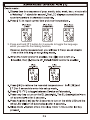
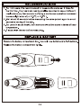
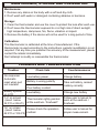
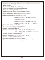
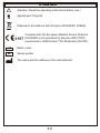
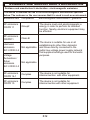
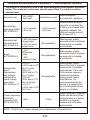
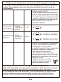
TALKING EAR AND FOREHEAD
THERMOMETER
INSTRUCTION MANUAL
MODEL: DX6635
Please read this manual before use
0197
- Thank you for purchasing our DX6635 Talking Multi-Functional Ear and
Forehead thermometer For a desirable use of this product, be sure to read
this user Panual before XVH
- )LUVWO\Rpen WKHbattery case and gently pull out thHSODVWLFVDIHW\WDE
7KHWhermometer will not activateXQWLOWKHWDEKDVEHHQUHPRYHG
- For safe and proper use of this product, be sure to read and fuIly understand
Safety PrecautionsVWHSVRXWOLQHGLQWKLVuser Panual
- .HHSWKLVPDQXDOLQDVDIHDQGDFFHVVLEOHORFDWLRQIRUHDV\DFFHVVDQG
IXWXUHUHIHUHQFH
SAFETY PRECAUTIONS
- Warning marks and symbols are GLVSOD\HG for your safHW\ and WRHQVXUH
SURSHUXVHRIthis product DQGSUHYHQWDQ\LQMXULHV
- See table below for description of warning marks and symbols:
WARNING
Means a possibility of personal injury in case of improper use.
NOTICE
Means a possibility of personal injury or property damage in case
of improper use.
[*Property damage covers any damage to house,family property, domestic animal.]
MARKS OR SYMBOLS
PROHIBITION
Means Forbidden with detailed items expressed in words or figures
within or beside the mark. 7KHH[DPSOHKHUHLV
General Forbidden
.
MUST OBSERVE
Means Obligatory with detailed items expressed in words or figures
within or beside the mark. 7KLVH[DPSOHKHUHLV
General compulsory
.
IMPLICATION OF SYMBOL
Means Type-B device.
INTENDED FOR USE
The device is intended for the intermittent measurement and monitoring of
human body temperature by consumers in the home.
P.1
Measurement should be suspended until the ear has adjusted to room
temperature.
P.2
P.3
1st of the manufacturing year
FRI
P.4
P.5
3. Press and hold [ T ] button for 2 seconds to toggle the language
which you want or non talking function.
P.6
P.7
P.8
MAINTENANCE, STORAGE AND CALIBRATION
Maintenance:
1. Remove any stains on the body with a soft and dry cloth.
2. Don't wash with water or detergent containing abrasive or benzene.
Storage:
1. Clean the thermometer and XVHWKH cover to protect the lens after each use.
2. Don't leave the thermometer exposed to or at high risk of direct sunOLJKW,
high temperature, dampness, fire, flame, vibration or impact.
3. Remove the battery LIWKHGHYLFHZLOOQRWEHXVHGIRUDORQJSHULRGRIWLPH.
Calibration:
This thermometer is calibrated at the time of manufactured. If the
thermometer is used according to the instructionV, periodic recalibration is not
required. If at any time you question the accuracy of the measurement, please
contact the retailer immediately.
Don't attempt to modify or reassemble the thermometer.
TROUBLES AND TROUBLESHOOTING
Troubles
No response/
Automatic
reset when pull
out insulator
Check lists
Countermeasures
/RZEattery SRZHU
Change battery
Battery in wrong polarity
Take out battery, reinsert
battery correctly
Poor battery contact
Battery symbol
on LCD
“Lo” on screen
(result below
32.0℃ or 89.6℉)
Low battery
Change new battery
Thermometer rightly pointed
at the eardrum / forehead?
Follow user’s manual to
point at the eardrum /
forehead.
“Hi” on screen
Please check the operation
(result below
42.9℃ or 109.3℉) method
P.9
Follow user’s manual for
proper measurement.
SPECIFICATION
Product Name: Talking Multi-Functional Ear and Forehead thermometer
Model: DX6635
Power supply: DC3V (2 x AAA battery)
Power consumption: <30mA (for voice prompt)
Temperature sensing Part: IR sensor
Measuring range: 32.0℃ ~ 42.9℃ (89.6℉ ~109.3℉)
Room Temperature: 5.0℃ ~ 59.9℃ (41.0℉ ~139.8℉)
Measuring accuracy: +/- 0.2℃ (or +/- 0.4℉)
from 35.5℃ ~ 42.0℃ (or 95.9℉ ~107.6℉)
+/- 0.3℃ (+/- 0.5℉)
from 35.0℃ ~ 35.4℃ (or 89.6℉ ~ 95.8℉)
from 41.2℃ ~ 42.9℃ (or 107.7℉ ~ 109.3℉)
Room Temperature: +/- 1℃ (2℉)
Outer dimension: 130(L)x41(W)X57(D)mm
Weight : 54g (without batteries)
Working environment: 10℃~ 40℃ (50.0℉~104.0℉) For Ear
15℃~40℃ (59.0℉~104.0℉) For Forehead
Relative humidity: 20%RH~85%RH
Storage environment: -10℃~ 55℃ (14℉~131℉)
Relative humidity: 20%RH~85%RH
Precision/repeatability: +/- 0.3℃ (+/- 0.5℉)
.
.
*Dispose of used batteries with care consult your distribution center for details.
P.10
SYMBOLS
Attention: Read the operating Lnstructions EHforH use !
Applied part of type B
Disposal in accordance with Directive 2002/96/EC (WEEE)
Complies with the European Medical Device Directive
and amended by directive 2007/47/EC
0197(93/42/EEC)
requirements. Notified body TÜV Rheinland (CE0197)
LOT
SN
Batch code
Serial number
The name and the address of the manufacturer
P.11
GUIDANCE AND MAUFACTU5ER'S DECLARATION
Guidance and manufacturer's declaration - electromagnetic emissions
The device is intended for use in the electromagnetic environment specified
below. The customer or the user assures that it is used in such an environment.
Emissions test Compliance
RF emissions
CISPR 11
Group2
RF emissions
CISPR11
Class B
Harmonic
Not applicable
emissions
lEC 61000-3-2
Voltage
fluctuations /
flicker
Not applicable
emissions
lEC 61000-3-3
Electromagnetic environment
- guidance
The device must emit electromagnetic e
energy in order to perform its intended
function. Nearby electronic equipment may
be affected.
The device is suitable for use in all
establishments other than domestic
and those directly connected to the
public low-voltage power supply network
that supplies buildings used for domestic
purposes.
RF emissions
CISPR 14-1
Complies
The device is not suitable for
interconnection with other equipment.
RF emissions
CISPR 15
Complies
The device is not suitable for
interconnection with other equipment.
P.12
Guidance and manufacturer's declaration — electromagnetic immunity
The device is intended for use in the electromagnetic environment specified
below. The customer or the user should assure that it is used in such an
environment.
Immunity test
IEC 60601
test level
Electrostatic
±6 kV contact
discharge (ESD)
±8 kV air
lEC 61000-4-2
Compliance level
Electromagnetic
environment - guidance
±6 kV contact
±8 kV air
Floors should be wood,
concrete or ceramic tile.
If floors are covered with
synthetic material, the
relative humidity should
be at least 30 %.
Electrical fast
transient/burst
IEC 61000-4-4
±2kV for power
supply lines
±1kV for input/
output lines
Not applicable
Mains power quality
should be that of a typical
commercial or hospital
environment.
Surge
IEC 61000-4-5
±1kV
differential
mode
±2kV
common mode
Not applicable
Mains power quality
should be that of a typical
commercial or hospital
environment.
Voltage dips,
short
interruptions
and voltage
variations on
power supply
input lines
IEC 61000-4-11
<5% UT
(>95% dip in UT)
for 0.5 cycle
40% UT
(60% dip in UT)
for 5 Cycles
70% UT
(30% dip in UT)
for 25 Cycles
<5% UT
(>95% dip in UT)
for 5 sec
Not applicable
Mains power quality
should be that of a typical
commercial or hospital
environment. If the user
of the device requires
continued operation
during power mains
interruptions, it is
recommended that the
device is powered from
an uninterruptible power
supply or a battery.
3 A/m
Power frequency magnetic
fields should be at levels
characteristic of a typical
location in a typical
commercial or hospital
environment.
Power frequency
(50/60Hz)
3 A/m
magnetic field
IEC 61000-4-8
NOTE: UT is the a.c. mains voltage prior to application of the test level.
P.13
Guidance and- manufacturer's declaration. Electromagnetic immunity
The device is intended for use in the electromagnetic environment specified
below. The customer or the user should assure that it is used in such an
environment.
Portable and mobile RF
Communications equipment should be
used no closer to any part of the device,
including cables, than the recommended
separation distance calculated from the
equation applicable to the frequency of
the transmitter. Recommended
separation distance.
Conducted R
F lEC 61000-4-6
3 Vrms
150 kHz to
80 MHz
3V
Radiated RF lEC
61000-4-3
3 V/m
80 MHz to
2.5 GHz
3 V/m
d=[ 3.5 ] p
V1
d=[ 3.5 ] p 80 MHz to 800 MHz
E1
d=[ 7 ] p 800 MHz to 2.5 GHz
E1
Where P is the maximum output power
rating of the transmitter In watts (W)
according to the. Transmitter
manufacturer and d is the recommended
separation distance in meters (m).
Field strengths from fixed RF
transmitters, as determined by an
electromagnetic site survey,a should be
less than the compliance level in each
frequency range.
Interference may occur Ln the
vicinity of equipment marked
with the following symbol:
NOTE I At 80 MHz ends 800 MHz. the higher frequency range applies.
NOTE 2 These guidelines may not apply in all situations. Electromagnetic propagation
is affected by absorption and reflection from structures, objects and people.
DField strengths from fixed transmitters, such as base stations for radio (cellular/
cordless) telephones and land mobile radios, amateur radio, AM and FM radio
broadcast and TV broadcast cannot be predicted theoretically with accuracy. To
P.14
assess the electromagnetic environment due to fixed RF transmitters,
an electromagnetic site survey should be considered. If the measured
field strength in the location in which the device is used exceeds the
applicable RF compliance level above, should be observed to verify
normal operation. If abnormal performance is observed, additional
measures may be necessary, such as reorienting or relocating the
device.
b Over the frequency range 150 kHz to 80 MHz, field strengths should
be less than [Vi] V/m.
Recommended separation distances between portable and mobile RF
communications equipment and the device
The device is intended for use in an electromagnetic environment in
which radiated RF disturbances are controlled. The customer or the user
of the device can help prevent electromagnetic interference by
maintaining a minimum distance between portable and mobile RF
communications equipment (transmitters) and the as recommended
below, according to the maximum output power of the communications
equipment.
Rated
Separation distance according to frequency of transmitter
maximum
150 kHz to 80 MHz 150 kHz to 80 MHz 150 kHz to 80 MHz
transmitter
output power of
d=[ 7 ] p
d=[ 3.5 ] p
d=[ 3.5 ] p
W
E1
V1
E1
0,01
0.12
0.12
0.23
0,1
0.38
0.38
0.73
1
1.2
1.2
2.3
10
3.8
3.8
7.3
100
12
12
23
For transmitters rated at a maximum output power not listed above, the
recommended separation distance d in meters (m) can be estimated using the
equation applicable to the frequency of the transmitter, where P is the
maximum output power rating of the transmitter in watts (W) accordable to the
transmitter manufacturer.
NOTE 1 At 80 MHz and 800 MHz. the separation distance for the higher
frequency range applies.
P.15
NOTE 2 These guidelines may not apply in all situations. Electromagnetic
propagation is affected by absorption and reflection from structures, objects
and people.
For transmitters rated at a maximum output power not listed above, the
recommended separation distance d in meters (m) can be estimated using the
equation applicable to the frequency of the transmitter, where P is the maximum
output power rating of the transmitter in watts (W) accordable to the transmitter
manufacturer.
NOTE At 80 MHz and 800 MHz. the separation distance for the higher
frequency range applies.
NOTE These guidelines may not apply in all situations. Electromagnetic
propagation is affected by absorption and reflection from structures, objects
and people.
WARRANTY
Two-year warranty is available from purchasing date, excluding user-caused
failures listed below:
(1) Failure resulted in unauthorized disassembly and modification
(2) Failure resulted in unexpected drop during application or transportation
(3) Failure resulted in operation away from proper instruction in user’s manual.
Present the Warranty Card with seal of distribution center (incI. name and
address) for repair free.
DECLARATION OF CONFORMITY
Shenzhen Dongdixin Technology Co., LTD declares that the DX6635
complies with following normative documents:
IEC60601-1, IEC60601-1-2, IEC60601-1-4, ASTM E1965-98,
ISO10993-5, ISO10993-10, ISO10993-1,ISO 14971,EN 12470-5.
P.16
1) Under the environment with electrostatic discharge, the unit may
malfunction and may require user to reset the unit.
2) Dispose with care, please consult the retailer for details.
Distributed by:
Omega Medical Instruments Pty Ltd
Suite 8, Level 12 101 Bathurst Street NSW 2000 AUSTRALIA
Manufacturer:
Name: Shenzhen Dongdixin Technology Co., LTD.
Add: No.3 Building XiliBaimang Xusheng Industrial
Estate, 518108 Nanshan, Shenzhen ChinD
Authorized EC-representative:
Shanghai International Holding Corp. GmbH (Europe)
Eiffestraße 80, 20537 Hamburg GeUPDQ\
Copyright 2011 by Shenzhen Dongdixin Technology Co., LTD.
Edition: V1.2
Printed in 2011
0197