1
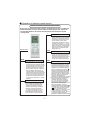
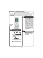
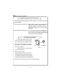
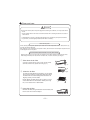
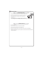
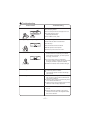
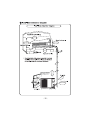
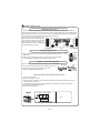
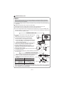
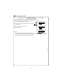
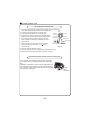
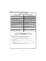
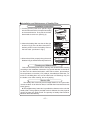
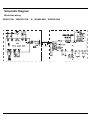
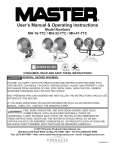
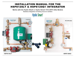
Split Air Conditioner
OWNER'S MANUAL
QUIETSIDE AIR CONDITIONERS
QSVSI-18A QSVSO-18A
QSVSI-24A QSVSO-24A
Thank you for choosing QUIETSIDE air conditioner. For correct operation,
please read this owner's manual carefully before operating the unit
and keep it carefully for consultation.
QSVSI-18A
QSVSI-24A
&217(176
2SHUDWLRQDQGPDLQWHQDQFH
Ƶ 1RWLFHVIRURSHUDWLRQ Ƶ 1RWLFHVIRUXVH Ƶ 1DPHVDQGIXQFWLRQVRIHDFKSDUW Ƶ2SHUDWLRQRIZLUHOHVVUHPRWHFRQWURO Ƶ(PHUJHQF\RSHUDWLRQ Ƶ&OHDQDQGFDUH Ƶ 7URXEOHVKRRWLQJ ,QVWDOODWLRQVHUYLFH
Ƶ1RWLFHVIRULQVWDOODWLRQ ,QVWDOODWLRQGLPHQVLRQGLDJUDP Ƶ
,QVWDOOLQGRRUXQLW
Ƶ
Ƶ
,QVWDOORXWGRRUXQLW
Ƶ &KHFNDIWHULQVWDOODWLRQDQGWHVWRSHUDWLRQ Ƶ ,QVWDOODWLRQDQG0DLQWHQDQFHRI+HDOWK\)LOWHU 7KLVV\PEROVWDQGVIRUWKHLWHPV
VKRXOGEHIRUELGGHQ
7KLVV\PEROVWDQGVIRUWKHLWHPV
VKRXOGEHIROORZHG
7KDQN\RXIRUFKRRVLQJQUIETSIDEDLUFRQGLWLRQHUSOHDVHUHDGWKLVRZQHU
VPDQXDO
FDUHIXOO\EHIRUHRSHUDWLQJWKHXQLWDQGNHHSLWFDUHIXOO\IRUFRQVXODWLRQ
7KHSURGXFWVLQWKLVPDQXDOPD\EHGLIIHUHQWZLWKWKHUHDORQHDFFRUGLQJWRGLIIHUHQW
PRGHOVVRPHPRGHOVKDYHGLVSOD\HUDQGVRPHPRGHOVZLWKRXWGLVSOD\HUWKHSRVLWLRQ
DQGVKDSHRIWKHGLVSOD\HUSOHDVHUHIHUWRWKHUHDORQH
7KLVDSSOLDQFHLVQRWLQWHQGHGIRUXVHE\SHUVRQVLQFOXGLQJFKLOGUHQZLWKUHGXFHG
SK\VLFHGVHQVRU\RUPHQWDOFDSDELOLWLHVRUODFNRIH[SHULHQFHDQGNQRZOHGJH
XQOHVVWKH\KDYHEHHQJLYHQVXSHUYLVLRQRULQVWUXFWLRQFRQFHUQLQJXVHRIWKHDSSOLDQFH
E\DSHUVRQUHSRQVLEOHIRUWKHLVDIHW\
&KLOGUHQVKRXOGEHVXSHUYLVHGWRHQVXUHWKDWWKH\GRQRWSOD\ZLWKWKHDSSOLDQFH
'RQRWGLVSRVHWKLVSURGXFWDVXQVRUWHGPXQLFLSDOZDVWH
&ROOHFWLRQRIVXFKZDVWHVHSDUDWHO\IRUVSHFLDOWUHDWPHQW
LVQHFHVVDU\
,PDJHVKRZQLQWKLVRSHUDWLQJLQVWUXFWLRQPDQXDOKHUHLV
LQGLFDWLYHRQO\$FWXDOSURGXFW\RXUHFHLYHPD\GLIIHU
2SHUDWLRQDQGPDLQWHQDQFHQRWLFHVIRURSHUDWLRQ
ƾ (DUWK7KHJURXQG ƾ%HVXUHWRdisconnectedWKH ƾ 6HOHFWWKHPRVWDSSURSULDWHWHP
EHFRQQHFWHG power SOXJZKHQQRWXVLQJWKH SHUDWXUH
air FRQGLWLRQHUIRUDORQJWLPH
.HHSURRPFRRl
HUWKDQRXWVLGH
DERXWGHJUHH
,IQRWSOHDVHDVNWKHTXDOLILHGSHUVRQ
QHOWRLQVWDOO)XUWKHUPRUHGRQ
WFRQQ
HFWHDFKZLUHWRWKHJDVSLSHZDWHU
SLSHGUDLQDJHSLSHRUDQ\RWKHULPSU
RSHUSODFHV
2WKHUZLVHWKHDFFXPXODWHGGXVW
PD\FDXVHILUHRUHOHFWULFVKRFN
ƾ 'RQ
WOHDYHZLQGRZVDQG
ƾ 'RQ
WEORFNWKHDLULQWDNHRURXWOHW
,WFDQGHFUHDVHWKHDLUFRQGLWLRQLQJ
FDSDFLW\
,WFDQGHFUHDVHWKHDLUFRQGLWLRQLQJ
FDSDFLW\RUFDXVHDPDOIXQFWLRQ
GRRUVRSHQIRUDORQJWLPH
ZKLOHRSHUDWLQJWKHDLUFRQGLWLRQHU
ƾ 3OHDVHQRWHZKHWKHUWKHLQVWDOOHG
VWDQGLVILUPHQRXJKRUQRW
,ILWLVGDPDJHGLWPD\OHDGWR
WKHIDOORIWKHXQLWDQGFDXVH
WKHLQMXU\
YHQWVRIERWKWKHRXWGRRUDQGLQGRRU
XQLWV
ƾ
'RQ
WVWHSRQWKHWRSRIWKH
RXWGRRUXQLWRUSODFHVRPHWKLQJ
RQLW
$VIDOOLQJRIIWKHRXWGRRUXQLW
FDQEHGDQJHURXV
,WFDQSUHFOXGHWKHHOHFWULFLW\ZDVWHG
ƾ .HHSFRPEXVWLEOHVSUD\DZD\
IURPWKHXQLWVPRUHWKDQP
,WFDQFDXVHDILUHRUH[SORVLRQ
ƾ
'RQ
WDWWHPSWWRUHSDLU
WKHDLUFRQGLWLRQHUE\\RXUVHOI
7KHZURQJUHSDLUZLOOOHDGWR
DQHOHFWULFVKRFNRUILUHVR
\RXVKRXOGFRQWDFWWKHVHUYLFH
FHQWHUWRUHSDLU
Notices for operation
ƾ If the supply cord is damaged, it must be replaced
ƾ 7KHDLUIORZGLUHFWLRQFDQEHDGMXVWHGDSSUR
SULDWHO\$WRSHUDWLQJDGMXVWWKHYHUWLFDODLUIORZ
GLUHFWLRQE\DGMXVWLQJWKHORXYHUVRIXSZDUGGR
ZQZDUGGLUHFWLRQ$QGWKHQKROGWZRHQGVRI
OHIWDQGULJKWORXYHUWRDGMXVWWKHKRUL]RQWDODLU
IORZ
by the manufacturer or its service agent or a
similarly qualified person in order to avoid a
hazard.
/RXYHURIOHIWULJKWGLUHFWLRQ
ƾ
'RQ
WLQVHUW\RXUKDQGVRUVWLFNLQWRWKHDLU
LQWDNHRURXWOHWYHQWV
/RXYHURIXSZDUG
GRZQZDUGGLUHFWLRQ
ƾ 'RQ
WEORZWKHZLQGWRDQLPDOVDQGSODQWV
GLUHFWO\,WFDQFDXVHDEDGLQIOXHQFHWRWKHP
2WKHUZLVHLWZLOOFDXVHDFFLGHQW
ƾ 'RQ
WDSSO\WKHFROGZLQGWRWKHERG\IRUD
ƾ 'RQ
WXVHWKHDLUFRQGLWLRQHUIRURWKHUSXUSRVHV
VXFKDVGU\LQJFORWKHVSUHVHUYLQJIRRGVHWF
ORQJWLPH
,WFDQFDXVHWKHKHDOWKSUREOHPV
ƾ 6SODVKLQJZDWHURQWKHDLUFRQGLWLRQHUFDQ
ƾ 'RQ
WSODFHDVSDFHKHDWHUQHDUWKHDLU
FDXVHDQHOHFWULFVKRFNDQGPDOIXQFWLRQ
FRQGLWLRQHU
2U&2WR[LFRVLVPD\RFFXUIRULPFRPSOHWH
EXUQLQJ
Notices for use
Working principle and special functions for cooling
Principle:
Air conditioner absorbs heat in the room and transmit to outdoor and discharged, so that
indoor ambient temperature decreased, its cooling capacity will increase or decrease by
outdoor ambient temperature.
Anti-freezing function:
If the unit is running in COOL mode and in low temperature, there will be frost formed on
the heat exchanger, when indoor heat exchanger temperature decreased below32 ℉ , the
indoor unit microcomputer will stop compressor running and protect the unit.
Working principle and special functions for heating
Principle:
* Air conditioner absorbs heat from outdoor and transmits to indoor, in this way to increase
room temperature. This is the heat pump heating principle, its heating capacity will be
reduced due to outdoor temperature decrease.
If outdoor temperature becomes very low, please operate with other heating equipments.
*
The Surplus Heat Blowing function:
when unit stop running, after the heating temperature arrived, indoor unit runs at setting
fan speed for 60s.
Anti-cool wind function:
In "Heat" mode, under the following three kinds of state, if indoor heat exchanger doesn't
arrive at certain temp., indoor fan will not act, in order to prevent cool wind blowing(within
2 mins):
1. Heating starts. 2.After Auto Defrost finished. 3.Heating under the low temperature.
Working temperature range
Indoor sideDB/WB(oF)
Outdoor sideDB/WB(oF)
Maximum cooling
89.6/73.4
Minimum cooling
69.8/59
69.8/-
Maximum heating
80.6/---
75.2/64.4
Minimum heating
68/---
19.4/17.6
109.4/78.8
The operating temperature range (outdoor temperature) for cooling unit is69.8℉~ 1 0 9 . 4 ℉
for cooling and heating unit is 19.4℉-109.4℉.
3
Notices for use
g All the electrical work must be done by qualified personnel according to relative wiring
regulation and this manual.
g The power supply is type Y connection.If the supply cord is damaged,it must be replaced by
the manufacturer or its service agent or a similarly qualified person in order to avoid a hazard.
g The rated voltage and the exclusive circuit must be used.
g Leakage circuit-breaker and air switch of correct capacity must be installed.the air switch
of 32A should be used in these models.
g The plug must be accessible after the appliances have been positioned.
Agair switch having a contact separation of at least 0.12inch in all poles should be fixed in fixed
wiring.
1DPHVDQGIXQFWLRQVRIHDFKSDUW
,QGRRUXQLW
(Image shown here is indicative only. Actual product you receive may differ)
$LULQOHW
)URQW3DQHO
'LVSOD\HU
:UDSSLQJ7DSH
)LOWHU
*XLGHSDQHO
:DOO3LSH
$LURXWOHW
:LUHOHVVUHPRWHFRQWURO
'LVSOD\LFRQ˄2QO\IRUVRPH8QLWV˅
3RZHU5XQ
&RROLQJ
+HDWLQJ
6HWWHPS
5HFHLYHU
'HKXPLGLI\
2XWGRRUXQLW
&RQQHFWLRQ SLSH
$LULQ
'UDLQDJHKRVH
$LURXW
Operation of wireless remote control
Names and functions of wireless remote control
Note: Be sure that there are no obstructions between receiver and remote controller;
Don't drop or throw the remote control; Don't let any liquid in the remote control and
put the remote control directly under the sunlight or any place where is very hot.
SLEEP
Signal transmitter
SLEEP button
ƽ
FAN
Press this button, Sleep On and Sleep
Off can be selected. After powered on,Sleep
Off is defaulted. After the unit is turned
off, the Sleep function is canceled. After
Sleep function set up, the signal of Sleep
will display. In this mode, the time of timer
can be adjusted. Under Fan and Auto
modes, this function is not available.
FAN button
ƽ Press this button, Auto, Low, Middle, High
speed can be circularly selected. After
powered on,Auto fan speed is default.
Under Dehumidify mode, Low fan speed
only can be set up.
Remote control
Low fan
Middle fan
High fan
ON/OFF
Note:Under the Dry mode, the fan speed isn't
adjustable, low fan speed is imperative,
but when operating this button, the wireless
adjustable, low fan speed is imperative,
ON/OFF button
ƽ Press
this button, the unit will be turned on,
press it once more, the unit will be turned
off. When turning on or turning off the unit,
the Timer, Sleep function will be canceled,
but the presetting time is still remained.
MODE
CLOCK
CLOCK button
ƽ Press this button, the clock can be set up,
signal blink and display.Within 5
seconds, the value can be adjusted by
pressing + or - button, if continuously
press this button for 2 seconds above,
in every 0.5 seconds, the value on ten place
of Minute will be increased 1. During blinking,
repress the Clock button, signal will be
constantly displayed and it denotes the
setting succeeded. After powered on, 12:00
is defaulted to display and signal will
be displayed. If there is signal be
displayed that denotes the current time
value is Clock value, otherwise is Timer value.
MODE button
ƽ
Press this button, Auto, Cool,Dry, Fan,
Heat mode can be selected circularly.
Auto mode is default while power on.
Under Auto mode,the temperature will not
be displayed; Under Heat mode, the
initial value is 28ć 82 R);Under other
modes, the initial value is 25ć 77 R)
LIGHT
LIGHT button
ƽ
AUTO
COOL
Press this button to select LIGHT on or off
in the displayer. When the LIGHT on is
set,the icon
will be displayed and the
DRY
indicator light in the displayer will be on.
FAN
When the LIGHT off is set, the icon
HEAT
(only for cooling and heating unit)
be displayed and the indicator light in the
displayer will be off.
will
Operation of wireless remote control
Names and functions of wireless remote control
Notice: This is a general use remote controller, it could be used for the air conditioners
with multifunction; For some function, which the model dosen't have, if press the
corresponding button on the remote controller that the unit will keep the original
running status.
+
Remote control
BLOW
-
For presetting temperature increasing.
Press this button,can set up the temperature,
when unit is on . Continuously press and
hold this button for more than 2 seconds,
the corresponding contents will be
changed rapidly, until unpress the button
then send the information, ć˄̧˅is displaying all along. In Auto mode, the temperature can not be set up, but operate this
button can send the signal. Centigrade
setting range :16-30; Fahrenheit scale
setting range 61-86.
ƽ
In Cool or Heat mode, press this button
can turn on or turn off the Turbo function.
After turned on the Turbo function, its
signal will be displayed. When switching
the mode or changing fan speed, this
function will be canceled automatically.
TURBO
BLOW button
ƽ
+ button
ƽ
TEMP
Press this button, can turn on or turn off
the drying.In Cool and Dehumidifying mode,
press this button and will display "BLOW",
at this time the Blow is turned on. If repress
this button,"BLOW" will be concealed, at
this time the Blow function is turned off.
After powered on, Blow OFF is defaulted.
When operating the ON/OFF button, or
switching mode to Cool or Dehumidifying
mode,the Blow function will keep the original
status. If unit is turned off, Blow OFF only
can be set up and send the signal. In Auto,
Fan as well as Heat mode, Blow function
can not be set up and there is no "BLOW"
displaying.
- button
ƽ Presetting temperature can be decreased.
Press this button, the temperature can be
set up, continuously press this button
and hold for two seconds, the relative
contents can quickly change, until unhold
this button and send the order that the ć
R
) signal will be displayed all the time.
The temperature adjustment is unavailable under the Auto mode, but the order
can be sent by if pressing this button.
TURBO button
TEMP button
ƽ Press
this button, could select displaying
the indoor setting temperature or indoor
ambient temperature.When the indoor unit
firstly power on it will display the setting
temperature, if the temperature's displaying
status is changed from other status to"
",
displays the ambient temperature, 5s later
or within 5s, it receives other remote control
signal that will return to display the setting
temperature. if the users haven't set up the
temperature displaying status,that will
display the setting temperature.
(This function is applicable to partial of models)
ƽ After powered on, the setting temperature
displaying is defaulted, (according to
customers requirements to display, if
there is no requirement that will default
to display the presetting temperature
and there is no icon displayed on wireless
remote control). Press this button,
(When displaying
) , will display
presetting temperature; (when displaying )
will display indoor ambient temperature,
current displaying status will not be
changed. If current displays indoor
ambient temperature, if received the other
remote control signal, it will display
presetting temperature, 5s later, will back
to display the ambient temperature.
(This function is applicable to partial of models)
Operation of wireless remote control
Names and functions of wireless remote control
Notice: This is a general use remote controller, it could be used for the air conditioners
with multifunction; For some function, which the model dosen't have, if press the
corresponding button on the remote controller that the unit will keep the original
running status.
TIMER ON
TIMER ON BUTTON
ƽ
Remote control
SWING UP AND DOWN BUTTON
ƽ
Timer On setting: Signal “ON” will blink
and display, signal
will conceal, the
numerical section will become the timer
on setting status. During 5 seconds blink,
by pressing ˇ or ˉ button to adjust the
time value of numerical section, every
press of that button, the value will be
increased or decreased 1 minute. Hold
pressing ˇ or ˉbutton, 2 seconds later,
it quickly change, the way of change is:
During the initial 2.5 seconds, ten numbers
change in the one place of minute, then
the one place is constant, ten numbers
change in the tens place of minute at 2.5
seconds speed and carry. During 5s blink,
press the Timer button, the timer setting
succeeds. The Timer On has been set up,
repress the timer On button, the Timer
On will be canceled. Before setting the
Timer, please adjust the Clock to the
current actual time.
TIMER OFF
TIMER OFF BUTTON
Press this button, to set up swing angle,
which circularly changes as below:
ƽ
OFF
This is an universal use remote controller. If
remote controller sends the following three
kinds of status that the swing status of main
unit will be:
When the guide louver start to swing up and
down, if turn off the Swing, the air guide louver
will stop at current position.
which indicates the guide louver swings up
and down between that all five positions.
Once press this key to enter into
TIMER OFF setup, in which case
the TIMER OFF icon will blink.
The method of setting is the same
as for TIMER ON.
Operation of wireless remote control
Guide for operation- General operation
1. After powered on, press ON/OFF button, the unit will start to run.(Note: When
it is powered off, the guide louver of main unit will close automatically.)
2. Press MODE button, select desired running mode.
3. Pressing +or - button, to set the desired temperature. (It is unnecessary
to set the temp. at AUTO mode.)
4. Pressing FAN button, set fan speed, can select AUTO FAN, LOW, MID
and HIGH.
5. Pressing
button, to select the swing.
Guide for operation- Optional operation
1. Press SLEEP button, to set sleep.
2. Press TIMER ON and TIMER OFF button, can set the scheduled timer on
or timer off.
3. Press LIGHT button, to control the on and off of the displaying part of the
unit (This function may be not available for some units).
4. Press TURBO button, can realize the ON and OFF of TURBO function.
Introduction for special function
ƾ About blow function
This function indicates that moisture on evaporator of indoor unit will be blowed after the unit
is stopped to avoid mould.
1. Having set blow function on: After turning off the unit by pressing ON/OFF button indoor
fan will continue running for about 10 min. at low speed. In this period, press blow button
to stop indoor fan directly.
2. Having set blow function off: After turning off the unit by pressing ON/OFF button, the
complete unit will be off directly.
ƾ About AUTO RUN
When AUTO RUN mode is selected, the setting temperature will not be displayed on the
LCD, the unit will be in accordance with the room temp. automatically to select the suitable
running method and to make ambient comfortable.
ƾ About turbo function
If start this function, the unit will run at super-high fan speed to cool or heat quickly so that
the ambient temp. approachs the preset temp. as soon as possible.
Operation of wireless remote control
ƾ About lock
Press +and - buttons simultaneously to lock or unlock the keyboard. If the remote controller
will be displayed on it, in which case, press any button, the mark will
is locked, the icon
flicker for three times. If the keyboard is unlocked, the mark will disappear.
ƾ About swing up and down
1. Press swing up and down button continuously more than 2s,the main unit will swing back
and forth from up to down, and then loosen the button, the unit will stop swinging and present
position of guide louver will be kept immediately.
2. Under swing up and down mode, when the status is switched from off to , if press this
button again 2s later,
status will switch to off status directly; if press this button again
within 2s,the change of swing status will also depend on the circulation sequence stated above.
ƾ About switch between Fahrenheit and Centigrade
With unit turned off, press MODE and - buttons simultaneously to switch ćanḑ
Changing batteries and notices
Slightly to press the place with
, along the arrowhead direction to push the back cover of wireless
remote control. (As show in figure)
Take out the old batteries. (As show in figure)
Insert two new AAA1.5V dry batteries, and pay attention to the polarity.
(As show in figure)
Attach the back cover of wireless remote control. (As show in figure)
ƾ NOTE:
ƽ When changing the batteries, do not use the old or different batteries,
otherwise, it can cause the malfunction of the wireless remote control.
ƽ If the wireless remote control will not be used for a long time, please
take them out, and don't let the leakage liquid damage the wireless
remote control.
ƽ The operation should be in its receiving range.
ƽ It should be placed at where is 1m away from the TV set or stereo sound sets.
ƽ If the wireless remote control can not operate normally, please take them out,
after 30s later and reinsert, if they cannot normally run, please change them.
Sketch map for
changing batteries
Emergency operation
Displayer indicator light control of indoor unit
It's a special selective buttonfor the users ,who are not accustomed to the
light at sleeping.
ƽ Get
the displayer indicator light on: When setting the light function,the mark will
display on the remote controller screen by
pressing this button. In which case,the dissplayer indicator light will be on if the AC receives
this signal.
ƽ Get
the displayer indicator light off: If cancel the light function,the mark
will disap-
per on the remote controller screen by pressing this
button. In which case, the displayer indicator light will
be off if the AC receives this signal.
Emergency operation
If the wireless remote control is lost
or broken, please use the manual switch
button. At this time, the unit will run at the
Auto mode, but the temperature and fan
speed cannot be changed. The operation
was shown as below:
Manual switch
Fig.3
To open the panel, the manual switch
is on the displayer box.
ƽ
Turn on the unit: Press
the button,the unit will run at Auto mode
immediately.The microcomputer will accord
to the indoor temperature to select (Cooling,
Heating, Fan) and obtain the comfortable effect.
ƽ
Turn off the unit: Press the button, the unit will stop working.
Clean and care
&DXWLRQ
ƽ
ƽ
ƽ
7XUQSRZHURIIDQGSXOORXWWKHSRZHUSOXJEHIRUHFOHDQLQJDLUFRQGLWLRQHURULWPD\FDXVH electric
VKRFN
1HYHUVSULQNOHZDWHURQWKHLQGRRUXQLWDQGWKHRXWGRRUXQLWIRUFOHDQLQJEHFDXVHLWFDQFDXVH an
HOHFWULFVKRFN
9RODWLOHOLTXLGHJWKLQQHURUJDVROLQHZLOOGDPDJHWKHDLUFRQGLWLRQHU6RZLSHWKHXQLWVZLWKD
GU\VRIWFORWKRUDFORWKVOLJKWO\PRLVWHQHGZLWKZDWHURUFOHDQVHU
&OHDQWKHIURQWSDQHO
:KHQFOHDQLQJWKHIURQWSDQHOSOHDVHGLSWKHFORWKLQWRWKHZDWHUWHPSHUDWXUHRIEHORZthen
to dry
ć
WKHFORWKDQGZLSHWKHGLUW\SDUW
1RWH3OHDVHGRQRWWRLPPHUVHWKHIURQWSDQHOLQZDWHUGXHWRWKHUHDUHPLFURFRPSXWHUFRPSRQHQWV and
FLUFXLWGLDJUDPVRQWKHIURQWSDQHO
&OHDQWKHDLUILOWHU5HFRPPHQGHGRQFHHYHU\WKUHHPRQWKV
127(,IGXVWLVPXFKPRUHDURXQGWKHDLUFRQGLWLRQHUWKHDLUILOWHUVVKRXOGEHFOHDQHGPDQ\WLPHV
$IWHUWDNLQJRIIWKHILOWHUGRQ
WWRXFKWKHILQRILQGRRUXQLWLQRUGHUWRDYRLGKXUW\RXUILQJHUV
ķ 7DNHGRZQWKHDLUILOWHU
$WWKHVORWRIVXUIDFHSDQHOWRRSHQDQDQJOHSXOOWKHDLUILOWHU
GRZQZDUGDQGWDNHLWRXWSOHDVHVHHWKH)LJDE
D
E
ĸ CleanWKHDLUILOWHU
)LJ
7RFOHDQWKHGXVWDGKHULQJWRWKHILOWHUV\RXFDQHLWKHU
XVHDYDFXXPFOHDQHURUZDVKWKHPZLWKZDUPZDWHU
WKHZDWHUZLWKWKHQHXWUDOGHWHUJHQWVKRXOGEHORZ
GHJUHHDQGGU\LWLQWKHVKDGH
127(1HYHUXVHZDWHUDERYHWRFOHDQRULWFDQ
ć
FDXVHGHIRUPDWLRQRUGLVFRORUDWLRQ1HYHUSDUFKLWE\
ILUHRUFDQFDXVHDILUHRUGHIRUPDWLRQ
Ĺ ,QVHUWWKHDLUILOWHU
5HLQVHUWWKHILOWHUVDORQJWKHGLUHFWLRQRIDUURZKHDGDQG
WKHQWRFRYHUWKHFRYHUDQGFODVSLW
&OHDQDQGFDUH
&KHFNEHIRUHXVH
ķ%HVXUHWKDWQRWKLQJREVWUXFWVWKHDLURXWOHWDQGLQWDNHYHQWV
ĸ&KHFNWKDWZKHWKHUJURXQGZLUHLVSURSHUO\FRQQHFWHGRUQRW
Ĺ&KHFNWKDWZKHWKHUWKHEDWWHULHVRIDLUFRQGLWLRQHUDUH
FKDQJHGRUQRW
ĺ&KHFNWKDWZKHWKHUWKHLQVWDOODWLRQVWDQGRIWKHRXWGRRU
XQLWLVGDPDJHGRUQRW,IGDPDJHGSOHDVHFRQWDFWWKHGHDOHU
0DLQWDLQDIWHUXVH
ķ7XUQPDLQSRZHURII
ĸ&OHDQWKHILOWHUDQGLQGRRUDQGRXWGRRUXQLWV
ERGLHV
Ĺ&OHDUGXVWDQGREVWUXFWLRQVIURPWKHRXWGRRUXQLW
ĺ5HSDLQWWKHUXELJLQRXVSODFHRQWKHRXWGRRUXQLWWRSUHYHQWLWIURPVSUHDGLQJ
Ļ
$GRSWWKHVSHFLDOVKLHOGWRFRYHUWKHRXWGRRUXQLWDYRLGWKHUDLQZDWHUGXVWHQWHULQWR
WKHXQLWDQGJHWUXVW
Troubleshooting
&$87,21
'RQ
WDWWHPSWWRUHSDLUWKHDLUFRQGLWLRQHUE\\RXUVHOILWFDQFDXVHDQHOHFWULFVKRFNRU
ILUH3OHDVHFKHFNWKHIROORZLQJLWHPVEHIRUHDVNLQJIRUUHSDLULWFDQVDYH\RXUWLPHDQG
PRQH\
3KHQRPHQRQ
7URXEOHVKRRWLQJ
1RWRSHUDWHLPPHGLDWHO\ZKHQWKHDLU
FRQGLWLRQHULVUHVWDUWHG
2QFHWKHDLUFRQGLWLRQHULVVWRSSHGLWZLOO
QRWRSHUDWHLQDSSUR[LPDWHO\PLQXWHVWR
SURWHFWLWVHOI
ƽ
:DLWLQJ
7KHUH
VXQXVXDOVPHOOEORZLQJIURPWKHRXWOHW
DIWHURSHUDWLRQLVVWDUWHG
ƽ 7KHXQLWKDVQRSHFXOLDUVPHOOE\LWVHOI,IKDV
WKDWLVGXHWRWKHVPHOODFFXPXODWHGLQWKH
DPELHQW
ƽ 6ROXWLRQPHWKRG&OHDQLQJWKHILOWHU
,ISUREOHPVWLOOKDVVRQHHGWRFOHDQDLU
FRQGLWLRQHU3OHDVHFRQWDFWZLWKthe authorized
PDLQWHQDQFHFHQWHU
6RXQGRIZDWHUIORZFDQEHKHDUGGXULQJ
WKHRSHUDWLRQ
,Q&22/PRGHVRPHWLPHVWKHPLVWHPLWWHG
IURPWKHDLURXWOHWYHQW
&UHDNLQJQRLVHFDQEHKHDUGZKHQVWDUWRU
VWRSWKHXQLW
ƽ
7KHDLUFRQGLWLRQHULVVWDUWHGZKHQLWLV
UXQQLQJWKHFRPSUHVVRUVWDUWHGRUVWRSSHG
UXQQLQJRUWKHXQLWLVVWRSSHGVRPHWLPHV
WKHUHLVVZRRVKRUJXUJOHWKHVRXQGLVGXH
WRUHIULJHUDQWIORZLQJWKH\DUHQRWPDOIXQFWL
RQV
ƽ
:KHQWKHLQGRRUWHPSHUDWXUHDQGKXPLGLW\
DUHYHU\KLJKWKLVSKHQRPHQRQZRXOG
KDSSHQ7KLVLVFDXVHGE\WKHURRPDLULV
VZLIWO\FRROHGGRZQ$IWHUUXQQLQJIRUDZKLOH
LQGRRUWHPSHUDWXUHDQGKXPLGLW\ZLOOIDOO
GRZQWKHPLVWZLOOGLHDZD\
ƽ
7KLVLVFDXVHGE\WKHexpansion and contraction of plastic due to the changes of temperaWXUH
7URXEOHVKRRWLQJ
3KHQRPHQRQ
7URXEOHVKRRWLQJ
ƽ +DVWKHSRZHUEHHQVKXWGRZQ"
7KHXQLWFDQQRWUXQ.
ƽ ,VSRZHUSOXJORRVHG"
ƽ ,VWKHFLUFXLWSURWHFWLRQGHYLFHWULSSHGRIIRUQRW"
ƽ ,VYROWDJHKLJKHURUORZHU"
7HVWHGE\SURIHVVLRQDOV
%UHDNLQJRII
&RROLQJ+HDWLQJHIILFLHQF\LVQRWJRRG
ƽ ,VWKH7,0(5FRUUHFWO\XVHG"
ƽ ,V7HPSVHWWLQJVXLWDEOH"
ƽ :HUHLQOHWDQGRXWOHWYHQWVREVWUXFWHG"
ƽ ,VILOWHUGLUW\"
ƽ $UHWKHZLQGRZVDQGGRRUVFORWKHG"
ƽ 'LG)DQVSHHGVHWDWORZVSHHG"
ƽ ,VWKHUHDQ\KHDWVRXUFHVLQWKHURRP"
:LUHOHVVUHPRWHFRQWUROLVQRWDYDLODEOH.
ƽ 7KHXQLWLVLQWHUIHUHGE\DEQRUPDORUIUHTXHQW
IXQFWLRQVVZLWFKRYHURFFDVLRQDOO\WKHFRQWUROOHU
FDQQRWRSHUDWH$WWKLVWLPH\RXQHHGWRSXOORXW
RIWKHSOXJDQGUHLQVHUWLW
ƽ ,VLWLQLWVUHFHLYLQJUDQJH"2UREVWUXFWHG"
7RFKHFNWKHYROWDJHLQZLUHOHVVUHPRWHFRQWURO inside
LVFKDUJHGRWKHUZLVHWRUHSODFHWKHEDWWHULHV
ƽ :KHWKHUWKHZLUHOHVVUHPRWHFRQWUROLVGDPDJHG
,IZDWHUOHDNDJHLQWKHURRP.
ƽ 7KHDLUKXPLGLW\LVRQWKHKLJKVLGH
&RQGHQVLQJZDWHURYHUIORZHG
ƽ
ƽ 7KHFRQQHFWLRQSRVLWLRQRILQGRRUXQLWGUDLQDJH
SLSHLVORRVHG
,IZDWHUOHDNDJHLQRXWGRRUXQLW.
ƽ :KHQWKHXQLWLVUXQQLQJLQ&22/PRGHWKH pipe
DQGFRQQHFWLRQRISLSHZRXOGEHFRQGHQVHG due
WRWKHZDWHUFRROHGGRZQ
ƽ :KHQWKHXQLWLVUXQQLQJLQ$XWR'HIURVWLQJ mode
WKHLFHWKDZHGDQGIORZHGRXW
ƽ :KHQWKHXQLWLVUXQQLQJLQ+($7PRGHWKH water
DGKHUHGRQKHDWH[FKDQJHUGULSSHGRII
1RLVHIURPLQGRRUXQLWHPLWWHG
ƽ 7KHVRXQGRIIDQRUFRPSUHVVRUUHOD\LVVZLWFKLQJ
RQRURII
ƽ :KHQWKHGHIURVWLQJLVVWDUWHGRUVWRSUXQQLQJ
LWZLOOVRXQG7KDWLVGXHWRWKHUHIULJHUDQWIORZHG
WRWKHUHYHUVHGLUHFWLRQ
7URXEOHVKRRWLQJ
3KHQRPHQRQ
,QGRRUXQLWFDQQRWGHOLYHUDLU.
7URXEOHVKRRWLQJ
ƽ ,Q+($7PRGHZKHQWKHWHPSHUDWXUHRI indoor
KHDWH[FKDQJHULVYHU\ORZWKDW will stop deliver
DLULQRUGHUWRSUHYHQWFRRO air. (Within 2min)
ƽ ,Q+($7PRGHZKHQWKHRXWGRRUWHPSHUDWXUH
LVORZRUKLJKKXPLGLW\WKHUHDUHPXFKIURVWEH
IRUPHGRQWKHRXWGRRUKHDWH[FKDQJHUWKDWWKH
XQLWZLOODXWRPDWLFDOO\GHIURVWLQGRRUXQLWVWRS
EORZLQJDLUIRUPLQ
'XULQJWKHGHIURVWLQJWKHUHLVZDWHUIORZLQJRXW
RUYDSRUEHSURGXFHG
ƽ ,QGHKXPLGLI\LQJPRGHVRPHWLPHVLQGRRU fan will
VWRSLQRUGHUWRDYRLGFRQGHQVLQJ water be vaporized DJDLQUHVWUDLQWHPSHUDWXUH rising.
0RLVWXUHRQDLURXWOHWYHQW.
ƽ
,IXQLWLVUXQQLQJXQGHUWKHKLJKKXPLGLW\IRU
DORQJWLPHWKHPRLVWXUHZLOOEHFRQGHQVHG
RQWKHDLURXWOHWJULOODQGGULSRII
,PPHGLDWHO\VWRSDOORSHUDWLRQVDQGSOXJRXWFRQWDFW
WKHGHDOHULQIROORZLQJVLWXDWLRQV
7KHUHLVKDUVKVRXQGGXULQJRSHUDWLRQ.
7KHWHUULEOHRGRUVHPLWWHGGXULQJRSHUDWLRQ.
:DWHULVOHDNLQJLQWKHURRP.
$LUVZLWFKRUSURWHFWLRQVZLWFKRIWHQEUHDNV.
&DUHOHVV\VSODVKZDWHURUVRPHWKLQJLQWRXQLW.
7KHUHLVDQDEQRUPDOKHDWLQSRZHUVXSSO\FRUG
DQGSRZHUSOXJ
6WRSUXQQLQJDQGSXOORXWRIWKHSOXJ
Installation Manual
,PSRUWDQW1RWLFHV
7KHXQLWLQVWDOODWLRQZRUNPXVWEHGRQHE\TXDOLILHGprofessional individualDFFRUGLQJWR
WKHORFDO codesDQGWKLVPDQXDO
:KHQUHlocatingWKHXQLWWRWKHRWKHUSODFHSOHDVH FRQWDFWZLWKWKHqualified professional
individual LQWKHORFDODUHD
%DVLF5HTXLUHPHQWV)RU,QVWDOODWLRQ3RVLWLRQ
,QVWDOOLQWKHIROORZLQJSODFHPD\FDXVHPDOIXQFWLRQ,ILWLVXQDYRLGDEOHFRQWDFWZLWK
VHUYLFHFHQWHUSOHDVH
ƽ 3ODFHZKHUHVWURQJKHDWVRXUFHVYDSRUVIODPPDEOHJDVRUYRODWLOHREMeFWDUHHPLWWHG
ƽ 3ODFHZKHUHKLJKIUHTXHQF\ZDYHVDUHJHQHUDWHGE\UDGLRHTXLSPHQWZHOGHUVDQG
PHGLFDOHTXLSPHQW
ƽ 3ODFHZKHUHDORWRIVDOLQLWLHVVXFKDVFRDVWH[LVWV
ƽ 3ODFHZKHUHWKHRLOPDFKLQHRLOLVFRQWDLQHGLQWKHDLU
ƽ 3ODFHZKHUHDVXOIXUHGJDVVXFKDVWKHKRWVSULQJ]RQHVLVJHQHUDWHG
ƽ 2WKHUSODFHZLWKVSHFLDOFLUFXPVWDQFH
,QGRRU8QLW,QVWDOODWLRQ3RVLWLRQ6HOHFWLRQ
7KHDLULQOHWDQGRXWOHWYHQWVKRXOGEHIDUIURPWKHREVWUXFWLRQPDNHVXUHWKDWWKHDLU
FDQEHcirculatedWKURXJKWKHZKROHURRP
6HOHFWDSRVLWLRQZKHUHWKHFRQGHQVateFDQEHHDVLO\GUDLQHGRXWDQGWKHSODFH
LVHDVLO\FRQQHFWHGIRURXWGRRUXQLW
6HOHFWDORFDWLRQZKHUHWKHFKLOGUHQFDQQRWUHDFK
&DQVHOHFWWKHSODFHVWURQJHQRXJKWRZLWKVWDQGWKHIXOOZHLJKWDQGYLEUDWLRQRI
WKHXQLW$QGZLOOQRWLQFUHDVHWKHQRLVH
%HVXUHWROHDYHHQRXJKVSDFHWRDOORZDFFHVVIRUURXWLQHPDLQWHQDQFH7KHKHLJKWRIWKH
LQVWDOOHGORFDWLRQVKRXOGEH98.42 inRUPRUHIURPWKHIORRU
6HOHFWDSODFHDERXW39.37 inRUPRUHDZD\IURP79VHWRUDQ\RWKHUHOHFWULFDSSOLDQFHV
6HOHFWDSODFHZKHUHWKHILOWHUFDQEHHDVLO\WDNHQRXW
Make sure that the indoor unit installation should accord with installation dimension
diagram requirements.
Do not use the unit in the immediate surroundings of a laundry, bath, shower or a
swimming pool.
2XWGRRU8QLW,QVWDOODWLRQ3RVLWLRQ6HOHFWLRQ
6HOHFWDORFDWLRQIURPZKLFKQRLVHDQGRXWIORZDLUHPLWWHGE\XQLWZLOOQRWbe LQFRQYHQLHQFH
to QHLJKERUVDQLPDOVSODQWV
6HOHFWDORFDWLRQZKHUHWKHUHVKRXOGEHVXIILFLHQWYHQWLODWLRQ
6HOHFWDORFDWLRQZKHUHWKHUHVKRXOGEHQRREVWUXFWLRQVFRYHUWKHLQOHWDQGRXWOHWYHQW
7KHORFDWLRQVKRXOGEHDEOHWRZLWKVWDQGWKHIXOOZHLJKWDQGYLEUDWLRQRIWKHRXWGRRUXQLW
DQGSHUPLWVDIHLQVWDOODWLRQ
6HOHFWDGU\SODFHEXWGRQRWH[SRVHXQGHUWKHGLUHFWVXQOLJKWRUVWURQJZLQG
0DNHVXUHWKDWWKHRXWGRRUXQLWLQVWDOODWLRQGLPHQVLRQVKRXOGDFFRUGZLWKLQVWDOODWLRQ
GLPHQVLRQGLDJUDPFRQYHQLHQWIRUPDLQWHQDQFHUHSDLU
7KHKHLJKWGLIIHUHQFHRIFRQQHFWLQJWKHWXELQJZLWKLQ196.85 inWKHOHQJWKRIFRQQHFWLQJWKH
WXELQJZLWKLQ393.70 in
6HOHFWDSODFHZKHUHLWLVRXWRIUHDFKIRUWKHFKLOGUHQ
6HOHFWDSODFHZKHUHZLOOQRWEORFNWKHSDVVDJHDQGGRQRWLQIOXHQFHWKHFLW\DSSHDUDQFH
Installation Manual
6DIHW\5HTXLUHPHQWV)RU(OHFWULF$SSOLDQFHV
7KHSRZHUVXSSO\VKRXOGEHXVHGWKHUDWHGYROWDJHDQG$&H[FOXVLYHFLUFXLW
WKHSRZHUFDEOHGLDPHWHUVKRXOGEHVDWLVILHG
2. 'RQ
WGUDJWKHSRZHUFDEOHHPSKDWLFDOO\
3. ,WVKRXOGEHUHOLDEO\ groundHGDQG LWVKRXOGEHFRQQHFWHGWRWKHVSHFLDOgroundGHYLFH
WKHLQVWDOODWLRQVKRXOGEHperformed E\ aSURIHVVLRQDO
7KHDLUVZLWFK PXVWKDYHWKHIXQFWLRQVRI PDJQHWLFWULSSLQJDQGKHDWWULSSLQJLQ RUGHU
WR SURWHFW WKH VKRUW FLUFXLW DQG RYHUORDGLQJ
4. The min. distance from the unit and combustive surface is 59.05 in.
5. The appliance shall be installed in accordance with national wiring regulations.
6. An all-pole disconnection switch having a contact separation of at least 0.12 in in all poles
should be connected in fixed wiring.
GroundUHTXLUHPHQWV
$LUFRQGLWLRQHULVW\SHI HOHFWULFDSSOLDQFHWKXVSOHDVHGRFRQGXFWUHOLDEOHground
PHDVXUH
7KH\HOORZJUHHQ WZRFRORU ZLUH LQ DLU FRQGLWLRQHULVgroundZLUHDQGFDQQRWEHXVHG
IRURWKHUSURSRVH,WFDQQRWEHFXWRIIDQGEHIL[LWE\VFUHZRWKHUZLVHLWZRXOGFDXVH
HOHFWULFVKRFN
7KHHDUWKUHVLVWDQFHVKRXOGDFFRUGWRWKH1DWLRQDO&ULWHULRQ
7KHXVHUSRZHUPXVWRIIHUWKHUHOLDEOHHDUWKLQJWHUPLQDO3OHDVHGRQ
WFRQQHFWWKH
HDUWKLQJZLUHZLWKWKHIROORZLQJSODFH
ķ
7DSZDWHUSLSH. ĸ
*DVSLSH.
Ĺ
&RQWDPLQDWLRQSLSH.
ĺ 2WKHUSODFHVWKDWSURIHVVLRQDOSHUVRQQHOFRQVLGHUWKHPXQUHOLDEOH.
5The model and rating values for fuses according the silk print on fuse cover or related
PCB board.
5.90
in
Above
5.90 in Abov e
5.90 in Abov e
in
Ab
ov
e
98.43
in
Abov e
19.69 in Above
11
1
8 .1
1
.8
11
11.81 in Abov e
in
Ab
ov
e
19.69 in Above
n
78
.7
4i
o
Ab
ve
220.47 in
150 in
Install indoor unit
Install the rear panel
1.Always mount the rear panel horizontally. Due to the water tray of indoor unit has been adopted the
both-way drainage design, the outlet of water tray should be adjusted slightly down when installing, that is
taking the outlet of the water tray as the center of a circle, the included angle between the evaporator and
level should be 0 or more, that is good for condensing water drainage.
Wall
2.Fix the rear panel on the wall with screws. Wall
Mark on the middle of it
Gradienter
Space
Space
(Where is pre-covered with plastic granula)
3.Be sure that the rear panel has been fixed
firmly enough to withstand the weight of an
adult of 60kg, further more, the weight should
be evenly shared by each screw.
to the
wall
5.19inch
above
to the
wall
5.19inch above
Right
Left
¶
2.17inch
(Rear piping hole)
¶2.17inch
)LJ
(Rear piping hole)
Install the piping hole
Indoor
0DNHWKHSLSLQJKROHɎ2.17 inLQWKHZDOODWDVOLJKWGRZQZDUGVODQWWRWKH Wall pipe
outdoor side.
Outdoor
Seal pad
2.Insert the piping-hole sleeve into the hole to prevent the connection piping
and wiring from being damaged when passing through the hole.
Ø
Install the water drainage pipe
1.For good draining, the drain hose should be placed at a downward slant. Wrenched
2.Do not wrench or bend the drain hose or flood its end by water.
3.When the long drainage hose passing through indoor,
should wrap it with insulation materials.
Bent
Flooded
Connect indoor and outdoor electric wires
1.Open the surface panel.
2.Remove the wiring cover Fig.6.
3.Route the power connection cord from the back of the indoor unit and pull it toward the front through
the wiring hole for connection.
4.Connect the interconnection cord to the terminal block, and then fix the cord with cord anchorge.
5.Reassemble the clampand wiring cover.
6.Recover the surface panel.
for 18K 、24K models
brown
Fig.6
,QVWDOOLQGRRUXQLW
127(
:KHQFRQQHFWLQJWKHHOHFWULFZLUHLIWKHZLUHOHQJWKLVQRWHQRXJKSOHDVHFRQWDFWZLWK
WKHDXWKRUL]HGVHUYLFHVKRSWREX\DH[FOXVLYHHOHFWULFZLUHWKDWLVORQJHQRXJKDQGWKH
MRLQWRQWKHZLUHDUHQRWDOORZHG
7KHHOHFWULFZLULQJPXVWEHFRUUHFWO\FRQQHFWHGZURQJFRQQHFWLRQPD\FDXVHVSDUHSDUWV
PDOIXQFWLRQ
ƽ 7LJKWHQWKHWHUPLQDOVFUHZLQRUGHUWRSUHYHQWORRVH
ƽ
$IWHUWLJKWHQWKHVFUHZVOLJKWSXOOWKHZLUHDQGFRQILUPZKHWKHULVLWILUPRUQRW
ƽ
,IWKHHDUWKZLUHLVZURQJFRQQHFWLRQWKDWPD\FDXVHHOHFWULFVKRFN
ƽ
7KHFRYHUSODWHPXVWEHIL[HGDQGWLJKWHQWKHFRQQHFWLRQZLUHLILWLVSRRULQVWDOOHGWKDW
ƽ
WKHGXVWPRLVWXUHPD\HQWHULQRUWKHFRQQHFWLRQWHUPLQDOZLOOEHDIIHFWHGE\RXWVLGHIRUFH
DQGZLOOFDXVHILUHRUHOHFWULFVKRFN
,QVWDOOWKHLQGRRUXQLW
*DVVLGHSLSH
ƽ7KHSLSLQJFDQEHOHDGRXWIURPULJKWULJKWUHDUOHIW
OHIWUHDU
:KHQURXWLQJWKHSLSLQJDQGZLULQJIURPWKHOHIW
([WHUQDOFRQQHFWLRQ
HOHFWULFZLUH
/LTXLGVLGHSLSLQJ
7DLOLQJ
7DLOLQJ *DVVLGHSLSLQJ
RUULJKWVLGHRILQGRRUXQLWFXWRIIWKHWDLOLQJV
/LTXLGVLGH
LQVXODWLRQ
3LSLQJLQVXODWLRQ
)LQDOO\ZUDSLW
IURPWKHFKDVVLVLQQHFHVVDU\6KRZLQ)LJ
)LJ
:DWHUGUDLQDJHSLSH
ZLWKWDSH
Ł&XWRIIWKHWDLOLQJVZKHQURXWLQJWKHZLULQJRQO\
ł&XWRIIWKHWDLOLQJVDQGWDLOLQJVZKHQURXWLQJ
ERWKWKHZLULQJDQGSLSLQJ
/HIW
7DNHRXWWKHSLSLQJIURPERG\FDVHZUDSWKHSLSLQJ
েৢ
HOHFWULFZLUHZDWHUSLSHZLWKWDSHDQGSXOOWKHP
/HIWUHDU
5LJKW
WKURXJKWKHSLSLQJKROH$VVKRZLQ)LJ
)LJ
5LJKWUHDU
+DQJHWKHPRXQWLQJVORWVRIWKHLQGRRUXQLWRQWKH
)L[LQJKRRN
0RXQWLQJ
XSSHUWDEVRIWKHUHDUSDQHODQGFKHFNLILWLVILUP
EDRUG
0RXQWLQJ
HQRXJK$VVKRZLQ)LJ
SODWH
7KHKHLJKWRIWKHLQVWDOOHGORFDWLRQVKRXOGEH98.43 inch
RUPRUHIURPWKHIORRU
)LJ
7KHZDWHUGUDLQDJHSLSHFDQDOVREHLQVWDOOHGRQWKHOHIWRI
WKHLQGRRUXLQW
,QVWDOOWKHFRQQHFWLRQSLSH
$OLJQWKHFHQWHURIWKHSLSLQJIODUHZLWKWKH UHOHYDQWYDOYH
6FUHZLQWKHIODUHQXWE\KDQGDQGWKHQWLJKWHQWKH
QXWZLWKVSDQQHUDQGWRUTXHZUHQFKUHIHUWR WKH
IROORZLQJ
+H[QXWGLDPHWHU
Ɏ0.24in
Ɏ0.37in
Ɏ0.47 in
Ɏ0.63in
Ɏ0.75in
7LJKWHQLQJWRUTXH
1gP
̚
̚
̚
̚
̚
,QGRRUXQLWSLSLQJ
6SDQQHU
7DSHUQXW 3LSLQJ
7RUTXH
ZUHQFK
127()LUVWO\FRQQHFWWKHFRQQHFWLRQSLSHWRLQGRRUXQLWWKHQWRRXWGRRUXQLWSD\DWWHQWLRQ
WRWKHSLSLQJEHQGLQJGRQRWGDPDJHWKHFRQQHFWLRQ SLSHWKHMRLQWQXWFRXOGQ
WWLJKWHQWRR
PXFKRWKHUZLVHLWPD\FDXVHOHDNDJH
Install outdoor unit
Electric wiring
1. Disassemble the handle on the outdoor unit right side plate.
Handle
2.Take off cord anchorage. Connect and fix power connect
cord and power cord to terminal block.
for 220~240V models
N(1) 2
3
blue black
3.Fix the power connection cable and power cord with
L
N
brown
yellowgreen
Indoor unit
connection
cord anchorage.
for 208~230V models
4. Ensure wire has been fixed well.
N(1) 2
3
blue black
5. Install the handle.
L1
L2
brown
yellowgreen
Indoor unit
connection
GWH24MD-D3DNC5A
N(1) 2
3
L1
L2
G
yellow-
blue black
brown
green
NOTE:
L1 L2
Indoor
unit
Ɣ Wrong wiring may cause spare parts malfunction.
connection
Ɣ After the cable fixed, make sure there should be a free space between the connection
and connection and fixing place on the lead wire.
POWER CORD
22
Install outdoor unit
Air purging and leakage test
1. Connect charging hose of manifold valve to charge end of low pressure
valve (both high/low pressure valves must be tightly shut).
Manifold
Valve
2. Connect joint of charging hose to vacuum pump.
Multimeter
3. Fully open handle handle of Lo manifold valve.
-76cmHg
4. Open the vacuum pump to evacuate. At the beginning, slightly
Lo Handle
loosen joint nut of low pressure valve to check if there
Charging hose
is air coming inside. (If noise of vacuum pump has
been changed, the reading of multimeter is 0) Then
tighten the nut.
5. Keep evacuating for more than 15mins and make
sure the reading of multi-meter is -1.0 105pa
(-29.92inchHg)..
Manometer
Hi handle
Charging hose
Vacuum pump
Low pressure valve
Fig.10
6. Fully open high/low pressure valves.
7. Remove charging hose from charging end of low pressure valve.
8. Tighten bonnet of low-pressure valve. (As shown in Fig.10)
Condensate drainage of outdoor unit (no for cooling only)
The condensate and defrosting water formd during heating
in the outdoor unit can be properly discharged by drainage
pipe .
Installation method:set the drain connection in Ø0.98inch hole
of the chassis has been installed and then connect drainage
pipe with drain nozzle,so that condensate and defrosting waer
can be properly discharged.
23
Chassis
Drain
connection
&KHFNDIWHULQVWDOODWLRQDQGWHVWRSHUDWLRQ
&KHFNDIWHULQVWDOODWLRQ
,WHPVWREHFKHFNHG
3RVVLEOHPDOIXQFWLRQ
+DVLWEHHQIL[HGILUPO\"
7KHXQLWPD\GURSVKDNHRUHPLWQRLVH
+DYH\RXGRQHWKHUHIULJHUDQWOHDNDJHWHVW"
,WPD\FDXVHLQVXIILFLHQWFRROLQJKHDWLQJ
FDSDFLW\
,VKHDWLQVXODWLRQVXIILFLHQW"
,WPD\FDXVHFRQGHQVDWLRQDQGGULSSLQJ
,VZDWHUGUDLQDJHZHOO"
,WPD\FDXVHFRQGHQVDWLRQDQGGULSSLQJ
,VWKHYROWDJHLQDFFRUGDQFHZLWKWKHUDWHG
YROWDJHPDUNHGRQWKHQDPHSODWH"
,VWKHHOHFWULFZLULQJDQGSLSLQJ
FRQQHFWLRQLQVWDOOHGFRUUHFWO\DQGVHFXUHO\"
+DVWKHXQLWEHHQFRQQHFWHGWRDVHFXUH
HDUWKFRQQHFWLRQ"
,WPD\FDXVHHOHFWULFPDOIXQFWLRQ
RUGDPDJHWKHSDUW
,WPD\FDXVHHOHFWULFPDOIXQFWLRQ
RUGDPDJHWKHSDUW
,WPD\FDXVHHOHFWULFDOOHDNDJH
,VWKHSRZHUFRUGVSHFLILHG"
,WPD\FDXVHHOHFWULFPDOIXQFWLRQ
RUGDPDJHWKHSDUW.
,VWKHLQOHWDQGRXWOHWEHHQFRYHUHG"
,WPD\FDXVHLQVXIILFLHQWFRROLQJKHDWLQJ
FDSDFLW\
+DVWKHOHQJWKRIFRQQHFWLRQSLSHV
DQGUHIULJHUDQWFDSDFLW\EHHQUHFRUGHG"
7KHUHIULJHUDQWFDSDFLW\LVQRWDFFXUDWH
7HVW2SHUDWLRQ
%HIRUHWHVWRSHUDWLRQ
'RQRWVZLWFKRQSRZHUEHIRUHLQVWDOODWLRQLVILQLVKHGFRPSOHWHO\
(OHFWULFZLULQJPXVWEHFRQQHFWHGFRUUHFWO\DQGVHFXUHO\
&XWRIIYDOYHVRIWKHFRQQHFWLRQSLSHVVKRXOGEHRSHQHG
$OOWKHLPSXULWLHVVXFKDVVFUDSVDQGWKUXPVPXVWEHFOHDUHGIURPWKHXQLW
7HVWRSHUDWLRQPHWKRG
6ZLWFKRQSRZHUSUHVV212))EXWWRQRQWKHZLUHOHVVUHPRWHFRQWUROWRVWDUW
WKHRSHUDWLRQ
3UHVV02'(EXWWRQWRVHOHFWWKH&22/+($7&RROLQJRQO\XQLWLVQRWDYDLODEOH
)$1WRFKHFNZKHWKHUWKHRSHUDWLRQLVQRUPDORUQRW
4
Installation and Maintenance of Healthy Filter
Installation Instructions
1. Forcibly pull the panel for a specific angle
from the two ends of the front panel according
to the arrow direction. Then pull the air filter
downwards to remove it. (See Fig.a)
Fig. a
2. Mount the healthy filter onto the air filter,(as
shown in Fig.b). If the air filter cannot be installed, please mount the healthy filter on
the front case. (as shown in Fig.c)
Fig. b
Air filter
Healthy filter
Healthy filter
Fig. c
3. Mount the air filter properly along the arrow
direction in Fig.d, and then close the panel cover.
Fig. d
Cleaning and Maintenance
Take out the healthy filter before cleaning and reinstall it after cleaning
according to the installation instruction. Pay special attention to that silver
ion filter can't be cleaned with water, while active carbon, photocatalyst,
low temperature conversion (LTC) catalyst, formaldehyde eliminator, catechin or mite killing filter can, but can't with brush or hard things. Dry it in
the shade or sun after cleaning, but not by wiping.
Service Life
The healthy filter commonly has its usage lifetime for one year under
normal condition. As for silver ion filter, it is invalid when its surface becomes
black (green).
ƽ This supplementary instruction is provided for reference to the unit with
healthy filter. If the graphics provided herein is different from the physical
goods, the latter one shall prevail. The quantity of healthy filters shall be
based on the actual delivery.
5
Schematic Diagram
Electrical wiring
QSVSI-18A QSVSO-18A
& QSVSI-24A QSVSO-24A
QUIETSIDE CORPORATION
www.quietside.com
West Office
8750 Pioneer Blvd.
Santa Fe Springs, CA 90670 USA
Phone: 562-699-6066
Fax: 562-699-4351
East Office
6 Pine Hill Drive
Carlisle, PA 17013
Phone: 886-243-6498/ 717-243-2535
Fax: 717-243-7917
TX Office
3001 Northern Cross Blvd. Suite 361
Fort Worth, TX 76137
Phone: 817-838-6066
Fax: 817-838-8670
66129907432