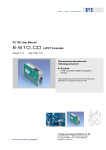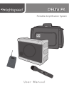
1
PZ 151E User Manual E-831 Release: 1.4.3 LVPZT Amplifier Modules Date: 2007-01-31 This document describes the following Product(s): E-831.02 Single-Channel, Low-Power Amplifier Module for LVPZTs © Physik Instrumente (PI) GmbH & Co. KG Auf der Römerstr. 1 ⋅ 76228 Karlsruhe, Germany Tel. +49-721-4846-0 ⋅ Fax: +49-721-4846-299 [email protected] ⋅ www.pi.ws E-831 Single-Channel LVPZT Amplifier User Manual PZ 151E Table of Contents 0. Manufacturer Declarations .............................................. 3 0.1. Certification .................................................................................. 3 0.2. Warnings and Safety Notices....................................................... 3 1. Introduction....................................................................... 4 2. Operating Principle........................................................... 5 3. Amplifier Description ....................................................... 6 3.1. Block Diagram.............................................................................. 6 3.2. Power Supplies ............................................................................ 6 4. Technical Data .................................................................. 7 5. Pin Assignment................................................................. 8 6. Dimensions ....................................................................... 8 © Copyright 2007 by Physik Instrumente (PI) GmbH & Co. KG Release: 1.4.3 File:E-831_02_User_PZ151E143.doc, 198144 Bytes Release 1.4.3 [email protected] Page 2 E-831 Single-Channel LVPZT Amplifier 0. Manufacturer Declarations 0.1. Certification User Manual PZ 151E Physik Instrumente (PI) GmbH & Co. KG certifies that this product met its published specifications at the time of shipment. 0.2. Warnings and Safety Notices Warning: High Voltage Can Cause Injury The PZT driver described in this document is power amplifier that outputs voltages of up to 120 V and may cause serious injury. High voltages can even be present on internally used, undocumented pins labeled “NC” or “RSVD”. When using PZT translators with bare contacts or non-isolated cases, do not touch the metallic surfaces. All work done with and on the devices described here requires adequate knowledge and training in handling High Voltages. Any cabling or connectors used with the system must meet the local safety requirements for the voltages and currents carried. Even if the PZT is not connected to the driver, the ceramic may be charged up to high voltage! When working with these devices or using PZT products from other manufacturers we strongly advise you to follow general accident prevention regulations! Caution: No Overvoltage, Polarity or ESD Protection Overvoltage or reversed polarity at the supply pins will destroy the module. No limiting components are included. ESD can also damage the circuit. The customer has to handle the module with the typical safety rules valid for other electronic components. Release 1.4.3 [email protected] Page 3 1. E-831 Single-Channel LVPZT Amplifier User Manual PZ 151E Introduction The E-831 LVPZT amplifier is a single-channel, amplifier for driving low-voltage piezoelectric translators (LVPZTs). It is an OEM module for PCB (printed circuit board) mounting and can be used as a one- or two-component amplifier for LVPZTs. The E-831.02 amplifier is a highly compact but complete driver for LVPZTs having an average output power of about 2 W (without heat sink) and 5 W with external heat sink. Because the power consumption of a piezoelectric translator depends on the operating frequency and displacement amplitude, static or quasi-static operation can be controlled by such a low-cost, low-power amplifier. E-831s require several different voltages for operation, including 127 VDC. All required voltages can be supplied by either the E-841 or E-842 power supply modules, which are in packages similar to the E-831 and run on single DC sources. See the corresponding user manuals for more information. Product Features: ¾ Designed for PCB mounting ¾ Low cost ¾ Small footprint ¾ Low noise ¾ Easy-to-use ¾ No external components ¾ Internal or external clocking ¾ Low profile ¾ High stability ¾ Fully stable for capacitive loads ¾ Fully overcurrent, short-circuit and temperature protected ¾ For small loads, operates without heat sink ¾ Powers up and down without voltage spikes Release 1.4.3 [email protected] Page 4 E-831 Single-Channel LVPZT Amplifier User Manual PZ 151E Warning: High Voltage Can Cause Injury The PZT driver described in this document is power amplifier that outputs voltages of up to 120 V and may cause serious injury. High voltages can even be present on internally used, undocumented pins labeled “NC” or “RSVD”. When using PZT translators with bare contacts or non-isolated cases, do not touch the metallic surfaces. All work done with and on the devices described here requires adequate knowledge and training in handling High Voltages. Any cabling or connectors used with the system must meet the local safety requirements for the voltages and currents carried. Even if the PZT is not connected to the driver, the ceramic may be charged up to high voltage! When working with these devices or using PZT products from other manufacturers we strongly advise you to follow general accident prevention regulations! 2. Operating Principle Low-voltage PZTs can be driven with an extended voltage range of -20 V to +120 V. This range can be fully covered by the E-831. Piezo actuators are, to a first approximation, capacitors, which means the current flow depends on the frequency of operation or, more generally, the slew rate of a changing signal. In static operation, almost no power will be needed. E-831 amplifier modules can be used for applications requiring a signal-amplifier. The operation mode is that of a power amplifier with a fixed gain of 10. This means for an output voltage swing of -20 to +120 V at the HV-OUT pin, the control voltage at the CONTROL IN pin has to run from -2 to +12 V. The output is fully compensated for capacitive loads from 0 μF (E-831) or 0.5 μF (E-832) to 10 µF, which is the typical range of PI's low-voltage piezo actuators. E-831 small-signal bandwidth is about 3 kHz. The output is subjected to 2 current limits: for short periods it can provide up to 100 mA, but the long-term limit is 50 mA. This allows to load a capacitor relatively fast but still makes the output circuit short-circuit-safe without time limitation. In the case temperature exceeds 70°C (can be reached after a few minutes with maximum current), an internal sensor will shut down the output stage until the temperature is below 60°C. This condition is signaled by a status line called TEMP-OFL. TEMP-OFL has 0 V for normal operation and +5 V for the over-temperature condition, during which HVOUT is 0 V . The MONITOR output provides a voltage signal internally divided to 1/100th of HV-OUT. Caution: No Overvoltage, Polarity or ESD Protection Overvoltage or reversed polarity at the supply pins will destroy the module. No limiting components are included. ESD can also damage the circuit. The customer has to handle the module with the typical safety rules valid for other electronic components. Release 1.4.3 [email protected] Page 5 E-831 Single-Channel LVPZT Amplifier 3. Amplifier Description 3.1. Block Diagram User Manual PZ 151E E-831 Schematic diagram GND, AGND and PGND lines are connected inside the module. For best performance supply voltages should be generated by a linear power supply. This allows taking full advantage of the excellent noise level of the amplifier module. If for space and power reasons a switched supply must be used, the one of the companion E-841 or E-842 modules is recommended. Naturally the switching frequency will appear in power supply and amplifier output, but at switching frequencies of 100 kHz, the piezo actuator is not able to follow, so that the resulting motion has much less noise than the driving voltage. This has to be considered if resolution is to be specified by measuring the piezo voltage. Especially with digital oscilloscopes, the measurement shows unrealistically high noise levels. The only real way is to measure the resulting motion with optical methods or other high-resolution, high bandwidth sensors. One possible problem with switched supplies is that the high frequencies can interact with other high frequencies in the system to generate lower-frequency noise that the actuator can follow. The solution is to synchronize the switching clock with the other system clocks, for example sensor excitation signals and sampling clocks for AD and DA converters. External synchronization lines are provided for this purpose. The PCB layout should allow for voltage levels which can be as high as 170 V between neighboring pins and up to 130 V from ground. This requires sufficient air gaps, depending on the application environment. 3.2. Power Supplies The E-831 requires voltages of ±15 V, -26 V and 127 V. To prevent the customer from having to generate such untypical voltages PI offers suitable power supply modules, which are similar in size and format to the E-831. While for low-noise / high-resolution applications linear power supplies are easier to design, most applications require smaller packages and low power losses. Piezo actuators, for mechanical and electrical reasons, are not able to generate mechanical noise at higher frequencies. Therefore power with switching frequency noise of 100 kHz is still suitable for high-resolution piezo positioning, even though the electrical signal itself might not qualify as “low-noise.” Release 1.4.3 [email protected] Page 6 E-831 Single-Channel LVPZT Amplifier User Manual PZ 151E Care should be taken if the system includes sensors with AC excitation or data sampling. If the different clock signals or their harmonics have frequencies relatively close together, their beat frequency can appear as noise. The solution PI provides is to make possible synchronization of the power supply with an external clock. In complex systems, or when the master clock is much higher and the various frequencies are made by dividers, more sophisticated synchronization circuits are sometimes necessary. This is because the phase shift of different dividers can affect precision and stability. See the E-841 / E-842 User Manual for detailed information on these modules. 4. Technical Data ..................................................................E-831.02 Function ....................................................LVPZT amplifier module Operating voltages:...................................+15 V / 20 mA (14 to 16 V) (all currents without dynamic load) ...........-15 V / 7 mA (-14 to -16 V) ..................................................................+127 V / 1.8 mA (+125 to 135 V) ..................................................................-26 V / 1.8 mA (-24 to -30 V) Output voltage swing: ...............................U+ -6 V (121 V for U+ = 127 V) ..................................................................U- +8 V (-20 V for U- = 28 V) Gain...........................................................10 ±0.1 Max. output current: ..................................100 mA/8 ms (sink/source) Max. average current: ...............................50 mA/2 min without heat sink Output protection: .....................................short circuit protected, the module is overload protected to 70° C case temperature Max. output power: ...................................2 W without ext. heat sink 5 W with ext. heat sink or forced airflow Control input range: ..................................-2 to +12 V Input impedance: ......................................100 kΩ Dynamic current requirements:.................depending on load, amplitude and slew rate Cut off frequency:......................................3.5 kHz, no load Ripple output: ............................................<1 mVpp (linear power supply, 1.8 µF load at the output) ..................................................................20 mVpp (switched power supply) Operating temperature range: ..................+5° to +50° Celsius Case..........................................................Metal shielded casing, size: 50 x 30 x 14 mm Soldering pins ...........................................1 mm diameter, 4 mm length Release 1.4.3 [email protected] Page 7 5. E-831 Single-Channel LVPZT Amplifier User Manual PZ 151E Pin Assignment Pin 1 Pin 2 Pin 3 Pin 4 Pin 5 Pin 6 Pin 7 Pin 8 Pin 9 Pin 10 Pin 11 6. Analog GND Temperature Overload Signal Control-Input (-2 to +12 V) High Voltage Output (-20 V to +120 V for LVPZT) Output Monitor (1:100) PGND, LVPZT-GND Supply Voltage +127 V Supply Voltage -26 V Supply Voltage -15 V Supply Voltage +15 V Supply Voltage GND Dimensions Decimal places separated by commas in drawings Heat sink mounting holes on top (heat sink not offered by PI) Release 1.4.3 [email protected] Page 8