1
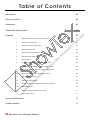
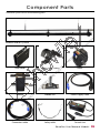
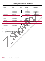
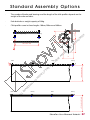
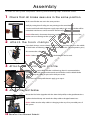
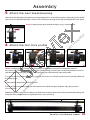
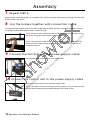
LI
AL
ND
SA
M
AG
E
CO
NT
EN
T
OF
TH
OC
IS
D
EN
T
UM
RT
PE
RO
AR
EP
Y
OF
SH
O
W
TE
X
S h ow Te x Use r M anual
K a buki
Ta b le o f Co nte nts
Introduction03
Safety Instructions 04
Component 05
Assembly 07
W
TE
X
Standard Assembly options06
AL
LI
M
AG
E
SA
ND
CO
NT
EN
T
OF
TH
IS
D
OC
UM
EN
T
AR
EP
RO
PE
RT
Y
OF
SH
O
1
Position all slidable pins in the same direction
07
2
Attach the hook clamps07
3
Assemble the click profile 10cm07
4
Attach the first brake07
5
Attach the next break/bearing08
6
Attach the first click profile08
7
Repeat step 608
8
Join the brakes together with connection cable
09
9
Connect the first brake to the power supply cable
09
10
Connect the control unit to the power supply cable
09
11
Connect the control unit to the power source
09
12
Activate the control unit10
13
Position the click profiles10
14
Test the Kabuki system without the curtain attached
10
15
Attach the curtain10
16
Test the Kabuki system with the curtain11
17
Repeat steps 14-1611
Care and Maintenance 12
Trouble shooting13
02
Sh owTe x Us er Manual K a buk i
I n t ro duc ti o n
The Kabuki-system is an easy to use electro-mechanical device used to create
spectacular unveilings.
·
This system was developed by ShowTex to drop lightweight fabrics, curtains, and objects
in order to reveal the stage, performers, or products.
·
Kabuki drop systems are used to form a complete fabric or curtain wall and drop
the entire piece at once.
·
It’s a modular system that can be endlessly extended by simply connecting the desired
length of brakes and bearings to Kabuki profiles.
·
The unique design will not release curtain in the event of a power outage.
RT
Y
OF
SH
O
W
TE
X
·
AL
LI
M
AG
E
SA
ND
CO
NT
EN
T
OF
TH
IS
D
OC
UM
EN
T
AR
EP
RO
PE
ShowTex User Ma nua l Ka bu ki
03
S a f e t y I ns tr ucti o ns
·
Read this user manual carefully
·
Profiles may only be used to move or carry light weight fabrics and objects (never people).
·
The maximum weight capacity per brake is 30 kg. Overloading the brakes can cause
damage to the system and endanger the safety of its users.
TE
X
·
Make sure that the area where the curtain will drop is always visible to the system
operator.
The system must be installed and activated by qualified technicians with knowledge
of its capabilities and limitations.
·
It is prohibited to stand under the suspended load at any time.
·
The system must be installed in a dry frost free environment.
·
The material to be dropped should be in good condition, checked and tested before use.
Safety cables must be secured and attached in a way that they can’t interfere with the
system’s movement.
PE
RO
AR
EP
EN
T
UM
OC
IS
D
TH
CO
NT
EN
T
OF
·
·
AL
LI
M
AG
E
SA
ND
·
04
RT
Y
OF
SH
O
W
·
Sh owTe x Us er Manual K a buk i
Com p o n e n t Pa r t s
TE
X
The Kabuki system consists of the following parts:
Hook Clamp 100 kg
Brake
ND
CO
NT
EN
T
OF
TH
IS
D
OC
UM
Click Profile
EN
T
AR
EP
RO
PE
RT
Y
OF
SH
O
W
Modulair Kabuki-systeem
Slidable Pin
Power Supply Cable
Safety cable
Control Unit
AL
LI
M
AG
E
SA
Bearing
Connection cable
ShowTex User Ma nua l Ka bu ki
05
Com p o n e n t Pa r t s
Click profile
Colour
Weight
Information
8150 0906 0107
8150 0906 1007
8150 0906 2007
8150 0906 3007
8150 0906 6007
0,18 kg/piece
1,85 kg/piece
3,70 kg/piece
5,55 kg/piece
11,10 kg/piece
Length: 10 cm
Length: 100 cm
Length: 200 cm
Length: 300 cm
Length: 600 cm
Hook Clamp
100 kg capactity
Brake
8150 0900 0007
8,96 kg/piece
230 V, 50 Hz, 0.2 A •
Carrying capacity: 30 kg
Bearing
8150 0903 0007
4,20 kg/piece
Slidable Pin
8150 0909 0005 INOX
0,02 kg/piece
Power Supply Cable
8150 0912 0027
0,40 kg/piece
Length: 2 m
Connection cable
8150 0915 0077
0,97 kg/piece
Length: 7 m
Control Unit
8150 0950 0010
0,82 kg/piece
TE
X
Art.nr.
LI
M
AG
E
SA
ND
CO
NT
EN
T
OF
TH
IS
D
OC
UM
Socket wrench (nr 17) for M10 (see STEP 2)
Extension cable (optional) (see STEP 10)
AL
06
OF
Y
RT
PE
RO
AR
EP
EN
T
Extra components::
•
•
SH
O
W
Name
S h owTe x Us er Manual K a buk i
St an d ard As s embl y O pti o ns
·
The number of brakes and bearings and the length of the click profiles depends on the
weight of the chosen fabric.
·
Each brake has a weight capacity of 30kg.
·
Click profiles come in three lengths: 100cm, 200cm and 300cm.
96
Bearing
61
10
SH
O
W
183
Brake Max weight 30kg
TE
X
Ø50
45,
225
OF
100 - 200 - 300
Y
RT
Bearing
RO
Brake
AR
EP
Brake
Bearing
Bearing
Brake
Bearing
ShowTex User Ma nua l Ka bu ki
< 1200cm Velvet 600gr/m2
Bearing
Brake
< 1200cm Velvet 600gr/m2
M
AG
E
LI
Brake
AL
Bearing
SA
ND
CO
NT
EN
T
OF
TH
IS
D
OC
+/-20
UM
Bearing
165
< 900cm Molton 300g/m2
10
EN
T
100 - 200 - 300
< 900cm Molton 300g/m2
10
Bearing
Bearing
PE
Brake Max weight 30kg
10
Brake
00°
07
As s embl y
I n order fo r t h e system to op erate corre c tl y the follow ing ste ps should b e t ake n:
1
C h eck t ha t all brake axe s are i n th e s am e p os i ti o n Make sure all brake axes are in the same position.
Verify by seeing that all safety pins are pointing in the same direction.
Connect each brake with the power supply separately. In this way, the brakes will be
unblocked and the axes can be moved to the desired position.
SH
O
Attach the hook clamps
OF
2
W
TE
X
Attention: Afterwards, disconnect the power supply cable. Prolonged tension of the
brakes can cause damage to the system.
RO
PE
RT
Y
If the hook clamps are not already attached, fasten the clamp hooks in the middle
of each brake and bearing. Use a socket wrench to do this. (see components parts)
AR
EP
Also connect the safety cable
IS
D
Attach the 10 cm click profile
TH
3
OC
UM
EN
T
Attention: Other types of hook clamps with bolt M10 can also be used.
CO
NT
EN
T
OF
If the curtain is used to hide all brakes and bearings, then it’s recommended to
position a 10 cm click profile at the outside end of the first and last Kabuki brake
position. Keep the safety pin pressed in while you do this.
LI
A tta c h t he fir s t brake
AL
4
M
AG
E
SA
ND
In case the 10cm click profile doesn’t apply, go to step 4.
Mount the first brake (together with the 10cm click profile) on the pipe/batten/truss.
Tighten the hook clamp and attach the safety cable to the pipe/batten/truss.
Attention: Make sure the safety cable isn’t hanging in the way of any movable parts of
the system.
08
Sh owTe x Us er Manual K a buk i
As s embl y
5
A tta c h t he next break / b e ar i n g Next, attach the following brake/bearing to the pipe/batten/truss at the desired position, depending on the profile
that is to be installed between them (1m,2m or3m). The break or bearing should still not be tightened at this phase.
OF
RT
Y
A tta c h t he fir s t click profi l e 1
OC
UM
EN
T
AR
EP
RO
PE
6
SH
O
W
TE
X
Attention: If required, reposition the hook clamp by using a socket wrench.
3
4
IS
D
2
CO
NT
EN
T
OF
TH
Attention: 4 slidable pins per running meter click profile are delivered standard for mounting the curtain to
the system. (see STEP 15) Depending on how the system is being used, extra pins can be used, however, it’s best to
add them before installing the profiles. 1 adjustable pin is provided with each 10cm click profile.
1 Assemble the first profile by supporting it on one side on the axis of the first brake. Do not slide the profile over
the safety pin yet..
SA
ND
2 Then pull the second brake or bearing closer.
(also see STEP 3)
M
AG
E
3 slide the other side of the profile over the respective axis. While doing this, keep the safety pin pressed in.
LI
4 When the profile is slid over the safety pin on both sides, install the hook clamp of the second brake/bearing and
AL
attach the safety cable around your pipe/batten/truss. (also see STEP 4)
ShowTex User Ma nua l Ka bu ki
09
As s embl y
7
R ep ea t STEP 6 Repeat STEP 6 until all the profiles are assembled. Finish off the last profile with a brake or bearing including a click
profile of 10cm. (see STEP 3)
8
J o in the brake s t ogeth e r wi th c on n e c ti on c a b l e
Connect the brakes together with a connection cable. When all brakes, bearings, and profiles have been correctly
assembled, connect them together with a connection cable.
SH
O
W
TE
X
Attention: Fasten any extra connection cable to the pipe/batten/truss to keep it out of
the way by using tape, cable fasteners, or back to back Velcro.
AR
EP
9
RO
PE
RT
Y
OF
Attention: The connection cables have a maximum length of 7m. Make sure that the
brakes are never installed further apart than 7m. Link cables longer than 7m are
available on request.
Co n n ect t he fir s t brake to th e p owe r s u p p l y c a b le
t he cont rol u n i t to th e p owe r s u p p l y c a bl e
ND
10C o n n ect
CO
NT
EN
T
OF
TH
IS
D
OC
UM
EN
T
Next, connect the first brake to the power supply cable.
SA
Next, connect the control unit to the power supply cable.
AL
LI
M
AG
E
Attention: This cable is maximum 3m long. If necessary, plan on using an extension cord
(not included), depending on the desired height of the Kabuki system.
10
Sh owTe x Us er Manual K a buk i
As s embl y
11 C o n n e ct
t he cont rol u n i t to th e p owe r s ou rc e
W
t he cont rol u n i t
SH
O
12A c tiva t e
TE
X
Next, connect the control unit to the power source (220V; 0,2 A).
UM
Po sition t he click p rofi l e s
OC
13
EN
T
AR
EP
RO
PE
RT
Y
OF
The standard setting of the switch is OFF. Switch to ON
to activate the control unit. The green DROP switch will
then light up.
OF
TH
IS
D
While keeping the DROP button pressed in, position the click profiles at a 45° angle
facing upwards. When the profiles are in the desired position, release the DROP
button. The brakes will then lock in place.
SA
LI
M
AG
E
the Ka buk i sys t em W IT HO UT th e c u r tai n a tta ch ed
AL
14T es t
ND
CO
NT
EN
T
Attention: Make sure the outer edges of the profiles match the frames of the brakes and
bearings.
Test the Kabuki system before installing the curtain by pressing in the DROP button.
Check that the system is free and that no obstacles are in the way to block profile
movement.
ShowTex User Ma nua l Ka bu ki
11
As s embl y
Atta ch t he cur t ain
TE
X
15
W
Attach the curtain to the slidable pins.
Y
RT
Tes t the Ka buk i sys te m W IT H th e c u r tai n
PE
16
OF
SH
O
Attention: Begin installation of the curtain at the outmost click profile measuring 10 cm if applicable to cover all
brakes and bearings.
s t eps 14 - 16
ND
17 Rep ea t
CO
NT
EN
T
OF
TH
IS
D
OC
UM
EN
T
AR
EP
RO
Next, test the Kabuki system with the curtain attached
by pressing the DROP button.
AL
LI
M
AG
E
SA
Please repeat steps 14-16 before every show!
12
Sh owTe x Us er Manual K a buk i
C a re a n d Ma i nte na nc e
The Kabuki system has components that must be regularly checked, maintained, and
replaced in order to ensure safety and keep it in good condition.
·
The best way to maintain the Kabuki system is to use it often. Each mechanical part should
be used at least once a week. In this way, residue and dirt can’t collect in the bearings and
irregular noises can be discovered in time.
·
More frequent maintenance is recommended in case of frequent use or in case the system
is installed in a space with a high degree of moisture, dust, or differences in temperature.
·
When necessary, disassemble the system in the same way it was installed.
AL
LI
M
AG
E
SA
ND
CO
NT
EN
T
OF
TH
IS
D
OC
UM
EN
T
AR
EP
RO
PE
RT
Y
OF
SH
O
W
TE
X
·
ShowTex User Ma nua l Ka bu ki
13
Tro u b le Sho o ti ng
What to do if the system stops working?
·
·
Verify that the system is correctly connected to the power supply.
Verify that all cables are connected to the correct outlets and that none
of them are damaged.
What to do if the curtain doesn’t drop?
SH
O
W
TE
X
Verify that the curtain can’t get stuck on any part of the system.
Check that the curtain isn’t too tightly tensioned on the system (in case the adjustable
pins are too far apart). In this case, lightweight fabrics will not drop correctly or at all.
Verify that the profiles can’t get caught on cables or light equipment.
AL
LI
M
AG
E
SA
ND
CO
NT
EN
T
OF
TH
IS
D
OC
UM
EN
T
AR
EP
RO
For more technical assistance please contact your local ShowTex office.
(see back cover of manual )
PE
RT
Y
OF
·
·
·
H AV E A GRE AT SHOW!
14
Sh owTe x Us er Manual K a buk i
www.showtex.com
LI
AL
ND
SA
M
AG
E
CO
NT
EN
T
OF
TH
OC
IS
D
EN
T
UM
RT
PE
RO
AR
EP
Y
OF
SH
O
W
TE
X