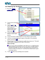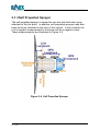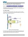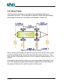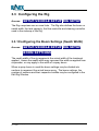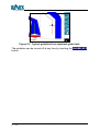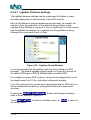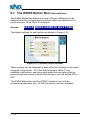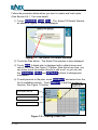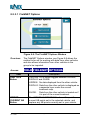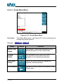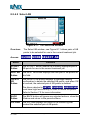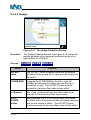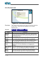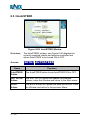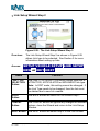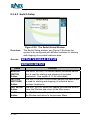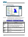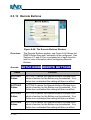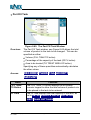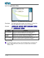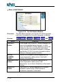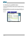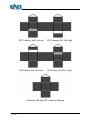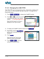
1
GuideTRAX V3.2
(HR)
User Manual
Software Version:
Part Number:
Revision:
Issue Date:
3.2
1-1259
A
April 2007
Copyright Notice
All rights reserved. No part of this publication may be reproduced, stored
in a retrieval system, or transmitted in any form or by any means,
electronic, mechanical photocopying, recording, or otherwise, without the
prior written permission of RINEX Technology.
Disclaimer
No liability is assumed with respect to the use of the information
contained herein. While every precaution has been taken in the
preparation of this publication, RINEX assumes no responsibility for
errors or omissions nor is any liability assumed for damages resulting
from the use of the information contained herein. Further this publication
and features described herein are subject to change without notice.
Use of this system is strictly limited to providing steering assistance to
the operator who must remain in control of the vehicle at all times.
RINEX, including its officers servants and agents, does not make any
representation to any party and will not accept any responsibility or
liability whatsoever for any loss or damage of whatever nature suffered
by any such person or corporation choosing or seeking to use this
system or any part thereof.
By use of this system you agree that RINEX is not liable or responsible
for any damage whatsoever to the vehicle, any property, personal
injuries, or death that may result from the use or abuse of this system.
GuideTRAX V3 User Manual
Written for GuideTRAX Version 3.2
Publication Date, April 2007
Copyright © 2007 by RINEX Technology. All rights reserved.
Acknowledgements
Windows XP® is registered to Microsoft Corp.
Other products and trademarks mentioned in this manual are the property of their
registered owners.
RINEX TECHNOLOGY
ABN: 30 029 441 181
Office Location :
19 Lyall Street
South Perth WA 6151
Postal Address :
PO Box 211
South Perth WA 6951
Telephone :
Local :
International :
(08) 9474 4771
+61-8-9474 4771
Facsimile :
Local :
International :
(08) 9474 4772
+61-8-9474 4772
Internet :
http://www.RINEX.com.au
Email :
[email protected]
RINEX LIMITED WARRANTY
Products
This warranty covers all products (the “Products”) manufactured and or sold by RINEX
Technology or their authorised dealers.
RINEX Technology Limited Warranty
RINEX Technology (“RINEX”) hereby warrants solely to the end purchaser of the Products,
subject to the exclusions and procedures set forth herein below, that the Products sold to
such end purchaser shall be free, under normal use and maintenance, from defects in
material and workmanship for a period of 12 months from delivery. Repairs and replacement
components are warranted, subject to the exclusions and procedures set forth below, to be
free, under normal use and maintenance, from defects in material and workmanship for 90
days from delivery, or for the balance of the original warranty period, whichever is greater.
Purchaser’s Exclusive Remedy
The end purchaser’s exclusive remedy under this warranty shall be limited to the repair or
replacement, at the option of RINEX, of any defective Products or components thereof. The
end user shall notify RINEX or a RINEX authorised dealer immediately of any claimed defect.
Repairs shall be made through RINEX only.
Exclusions
RINEX does not warrant damage occurring in transit or due to misuse, abuse, improper
installation, neglect, alteration, abnormal use, lightning (or other electrical discharge),
exposure to moisture or dampness, excessive temperatures, spill of liquids or fluids, or acts
of God. Repair, modification or service of RINEX products by any party other than an
authorised RINEX dealer shall render this warranty null and void. RINEX does not warrant
any Product where the Product serial number or nameplate has been removed, defaced or
altered. RINEX does not warrant claims asserted after the end of the warranty period.
RINEX does not warrant or guarantee the precision or accuracy of positions obtained when
using Products. The potential accuracy of Products as stated in RINEX literature and/or
Product specifications serves to provide only an estimate of achievable accuracy based on:
• Specifications provided by the US Department of Defense for GPS Positioning,
• GPS OEM Receiver specifications of the appropriate manufacturer (if applicable), and
• DGPS service provider performance specifications.
RINEX reserves the right to modify Products without any obligation to notify, supply or install
any improvements or alterations to existing Products.
No Other Warranties
The foregoing warranty is exclusive of all warranties, whether written, oral, implied or arising
by statute, course of dealing or trade usage, in connection with the design, sale, installation,
service or use of any products or any components thereof, including, but not limited to, any
warranty of merchantability or fitness for a particular purpose.
Limitation of Liability
The extent of RINEX’S liability for damages of any nature to the end purchaser or any other
person or entity whether in contract or tort and whether to persons or property shall in no
case exceed, in the aggregate, the cost of correcting the defect in the Product or, at RINEX’S
option, the cost of replacing the defective item. In no event will RINEX be liable for any loss
of production, loss of profits, loss of use for any special, indirect, incidental, consequential or
contingent damages, even if RINEX has been advised of the possibility of such damages.
Without limiting the foregoing, RINEX shall not be liable for any damages of any kind
resulting from installation, use, quality, performance or accuracy of any products.
RINEX LIMITED WARRANTY
Governing Legislation
To the greatest extent possible, this warranty shall be governed by the laws of the State of
Western Australia. In the event that any provision hereof is held to be invalid by a court of
competent jurisdiction, such provision shall be severed from this warranty and the remaining
provisions shall remain in full force and effect.
Obtaining Warranty Service
In order to obtain warranty service, the end purchaser must bring the Product to an
authorised RINEX dealer along with the end purchaser’s proof of purchase. The end
purchaser must produce the original invoice or other purchase documents as proof of the
purchase date.
The end purchaser is solely responsible for the cost of transportation of the Product to
RINEX or an authorised RINEX dealer and the Product is at the end purchaser's risk whilst in
transit.
For any questions regarding warranty service or to obtain information regarding the location
of any of RINEX’s approved dealers, contact RINEX at the following address:
RINEX Technology
19 Lyall Street
South Perth
Western Australia 6151
Telephone :
(08) 9474 4771
Facsimile :
(08) 9474 4772
Internet :
www.RINEX.com.au
TABLE of CONTENTS
GuideTRAX V3
1
Introduction .....................................................................................1
1.1
1.2
1.3
This Manual.................................................................................................. 4
The Saturn Series ........................................................................................ 5
GuideTRAX V3............................................................................................. 6
1.3.1
1.3.2
1.3.3
2
Saturn HL Version ........................................................................................6
Saturn HT Version ........................................................................................6
Saturn HR Version........................................................................................7
Getting Started ................................................................................9
2.1
2.2
2.3
2.4
2.5
2.6
Starting the System .................................................................................... 12
The Startup Screen .................................................................................... 13
The Main Screen ........................................................................................ 14
Map Screen................................................................................................ 16
Virtual Road Window.................................................................................. 17
Status Bar .................................................................................................. 19
2.6.1
2.7
GPS Status Indicator.................................................................................. 22
2.7.1
2.8
2.9
AutoSTEER Button.....................................................................................21
GPS Status Window ...................................................................................23
Registering the System .............................................................................. 25
Setting Up The First Time .......................................................................... 26
2.9.1
2.9.2
2.9.3
2.9.4
2.9.5
2.9.6
Setting The Season, Client, Farm and Driver.............................................26
Selecting the Current Job Details ...............................................................27
Setting Up Vehicles ....................................................................................28
Setting Up The Boom .................................................................................31
Setting Up The Tank...................................................................................32
Setting Up Master And Section Switches ...................................................32
2.10 Connecting the GPS................................................................................... 34
2.11 Recording a Treatment............................................................................... 35
3
Vehicles & Booms.........................................................................37
3.1
Configuring The Vehicle ............................................................................. 40
3.1.1
3.1.2
3.1.3
3.2
Configuring The Towed Implement ............................................................ 43
3.2.1
3.2.2
3.3
Pig Trailer ...................................................................................................43
Dog Trailer..................................................................................................44
Configuring the Rig..................................................................................... 45
3.3.1
4
Tractor ........................................................................................................40
Articulated Tractor ......................................................................................41
Self Propelled Sprayer................................................................................42
Configuring the Boom Settings (Swath Width) ...........................................45
Fields & Virtual Memory ...............................................................47
4.1
Virtual Memory ........................................................................................... 49
TABLE of CONTENTS
4.2
4.3
4.4
4.5
4.6
4.7
5
Setting Up the Season, Client, Farms and Fields....................................... 50
Starting a New Field ................................................................................... 51
Saving a Field ............................................................................................ 52
Viewing Field Information ........................................................................... 53
Unarchiving An Archived Field ................................................................... 54
Transferring and Backing Up Saved Fields ................................................ 55
Using Guidance.............................................................................57
5.1
Creating a Guideline................................................................................... 60
5.1.1
5.1.2
5.1.3
5.2
Replay Guidance........................................................................................ 67
5.2.1
5.2.2
5.3
Virtual Road Information.............................................................................69
Lightbar.......................................................................................................70
Guidelines and offsets................................................................................ 72
5.4.1
5.4.2
6
Loading a Treatment File To Be Replayed.................................................67
Setting Up RePLAY Guidance....................................................................68
Guidance information ................................................................................. 69
5.3.1
5.3.2
5.4
Parallel Guidance .......................................................................................61
Racetrack (Lock) Guidance ........................................................................63
Contour Lines Method ................................................................................65
Guide Overlap ............................................................................................72
Guide Offset ...............................................................................................73
Customising the System ..............................................................75
6.1
6.2
Enabling Options By Password .................................................................. 77
GPS Configurations.................................................................................... 78
6.2.1
6.2.2
6.2.3
6.3
Guidance Information ................................................................................. 81
6.3.1
6.3.2
6.3.3
6.3.4
6.4
Night Mode .................................................................................................85
Grid.............................................................................................................85
Measurement Units ....................................................................................85
Position Units..............................................................................................85
Field Colour ................................................................................................86
Status Bar...................................................................................................86
AutoFIELD.................................................................................................. 87
6.5.1
6.5.2
6.6
Heads Up/North Up ....................................................................................81
Zooming In and Out While Driving..............................................................82
Virtual Road................................................................................................82
Lightbar.......................................................................................................83
The Screen................................................................................................. 85
6.4.1
6.4.2
6.4.3
6.4.4
6.4.5
6.4.6
6.5
Defaults ......................................................................................................78
Changing the GPS Settings........................................................................78
Using e-Dif (Optional Extra)........................................................................80
The Background Map .................................................................................87
Treat Unmapped Field................................................................................88
Turning Treatment Recording ON and OFF ............................................... 89
6.6.1
6.6.2
The RINEX Toggle Switch..........................................................................89
Using Touch Instead Of a Switch ...............................................................91
TABLE of CONTENTS
6.6.3
6.7
6.8
6.9
The RINEX Button Box (Optional Extra)..................................................... 92
The RINEX Foot Switch (Optional Extra) ................................................... 93
The Multi Section Boom Interface (Optional Extra) .................................... 96
6.9.1
6.9.2
7
Installation ..................................................................................................96
Enabling the MSBI......................................................................................96
Using Record Keeping Functions ...............................................99
7.1
Common Record Keeping Tasks...............................................................101
7.1.1
7.1.2
7.1.3
7.1.4
7.1.5
7.1.6
7.1.7
7.1.8
7.1.9
7.1.10
7.2
7.3
Creating and Selecting a Driver................................................................115
Viewing Treatment History ........................................................................117
7.3.1
7.3.2
7.3.3
7.4
7.5
Creating and Loading a Treatment Plan...................................................101
Using Default Plans ..................................................................................104
Editing a Plan ...........................................................................................105
Filling The Tank ........................................................................................106
Dumping The Tank ...................................................................................109
Creating a Product Batch .........................................................................110
Importing Plans Created In The Office .....................................................112
Exporting Data To The Office ...................................................................112
Creating a Weather Record......................................................................113
Using Flags...............................................................................................114
Driver Setup ..............................................................................................115
7.2.1
Viewing a Saved Treatment .....................................................................117
Viewing a Farm Map and Creating Pages................................................118
Creating and Selecting a Filter .................................................................119
Creating Products......................................................................................120
AutoFIELD.................................................................................................121
7.5.1
8
Connecting Directly to a Third Party Controller ..........................................91
Mapping....................................................................................................121
The Menu System........................................................................125
8.1
8.2
Menu Layout .............................................................................................128
The Main Menu .........................................................................................130
8.2.1
8.2.2
8.2.3
8.2.4
8.3
View..........................................................................................................131
Field..........................................................................................................132
FieldNET...................................................................................................135
Guide ........................................................................................................139
General Setup ...........................................................................................147
8.3.1
8.3.2
8.3.3
8.3.4
8.3.5
8.3.6
8.3.7
8.3.8
8.3.9
8.3.10
About GuideTRAX ....................................................................................151
Current Job...............................................................................................153
AutoSTEER ..............................................................................................157
AutoFIELD ................................................................................................158
Display Setup ...........................................................................................159
Vehicle Setup ...........................................................................................162
AutoSPRAY ..............................................................................................179
Transfer Files............................................................................................181
Guide Options...........................................................................................182
Lightbar Setup ..........................................................................................184
TABLE of CONTENTS
8.3.11
8.3.12
8.3.13
8.3.14
8.3.15
8.3.16
8.4
Records.....................................................................................................213
8.4.1
8.4.2
8.4.3
8.4.4
9
Virtual Road Setup ...................................................................................186
GPS Setup................................................................................................188
Remote Buttons........................................................................................190
Sound Setup.............................................................................................192
Memory Setup ..........................................................................................194
FieldNET Setup ........................................................................................212
Tank Menu................................................................................................214
Weather Menu ..........................................................................................233
Flags.........................................................................................................239
History ......................................................................................................240
AutoSPRAY..................................................................................255
9.1
9.2
AutoSPRAY Overview...............................................................................258
Configuring AutoSPRAY ...........................................................................258
9.2.1
9.2.2
9.2.3
9.2.4
9.3
Enabling the AutoSPRAY Option .............................................................259
Setting AutoSPRAY Overlap ....................................................................260
Setting AutoSPRAY Latency Values ........................................................260
AutoSPRAY Section Translation ..............................................................264
Using AutoSPRAY in the Field ..................................................................266
9.3.1
9.3.2
Overriding AutoSPRAY ............................................................................268
AutoSPRAY Status Messages .................................................................271
10 AutoSTEER ..................................................................................273
10.1 Setting up AutoSTEER..............................................................................276
10.1.1
10.1.2
Selecting the AutoSTEER Controller........................................................276
Enabling AutoSTEER ...............................................................................277
10.2 Engaging AutoSTEER...............................................................................279
10.2.1
Disengaging AutoSTEER .........................................................................280
10.3 The AutoSTEER Status Button .................................................................281
11 FieldNET ......................................................................................283
11.1 What is FieldNET ......................................................................................285
11.2 Setting Up FieldNET..................................................................................286
11.2.1
11.2.2
11.2.3
Hardware Installation................................................................................286
Creating and Setting The Group ID ..........................................................287
Configuring FieldNET ...............................................................................289
11.3 Using FieldNET .........................................................................................290
11.3.1
11.3.2
11.3.3
11.3.4
Connecting To Another Vehicle In The Group..........................................290
Understanding the LINK TYPE.................................................................291
Changing the LINK TYPE.........................................................................292
Understanding The Status Of Other Vehicles ..........................................293
12 The Launcher...............................................................................295
12.1 Opening the Launcher...............................................................................298
12.2 Using the Launcher ...................................................................................300
12.2.1
Launcher Main Menu................................................................................301
TABLE of CONTENTS
12.2.2
12.2.3
12.2.4
12.2.5
System Tools............................................................................................303
Utilities ......................................................................................................305
GPS Tools ................................................................................................306
RINEX Tools.............................................................................................308
13 APPENDIX....................................................................................311
TABLE of CONTENTS
1
Introduction
GPS guidance systems allow agricultural machinery to be far more
productive by providing accurate and real time information for vehicle
navigation and placement of product. Specifically the RINEX guidance
systems provide an easy to use interface through the colour touch
screen for vehicle guidance. The system may be used for any
agricultural task which requires vehicle navigation, particularly for
applications or treatment of chemicals and/or fertilisers and seeds.
Treated areas can be seen on the screen as the vehicle is working,
providing a continuous guidance display with additional information
relating to the field and treatment. The RINEX guidance system records
information until it is manually cleared so operations can be interrupted if
necessary, and completed at a later date.
GuideTRAX V3 has been developed by RINEX primarily for vehicle
guidance in agricultural applications. In addition to this GuideTRAX V3
can be configured for control of automated steering systems and/or
automated boom section control.
GuideTRAX has evolved over many years and the release of
GuideTRAX V3 software heralds a new era with the addition of field
planning and data management modules to further enhance the
guidance software.
GuideTRAX V3 is configured for three different user levels. The system,
depending upon purchase is configured as either a HL, HT, or HR model.
Each model is described in a separate manual.
Accordingly this manual is specifically designed to assist users of the
Saturn guidance systems in the operational use of GuideTRAX V3 HR
software.
GuideTRAX V3.2 (HR) User Manual
P/n 1-1259
Page 3
Rev A
1.1 This Manual
This manual is designed for use with the Saturn HR model guidance
system as manufactured by RINEX.
This manual will refer to buttons which appear on the screen. The
screen is touch sensitive, which means that the system is operated by
touching the buttons on the screen. The user should touch the button on
the screen with their finger to select the button.
This manual will adopt the following conventions when describing the
selection of a button or a series of buttons in order to access a particular
function or section of the program.
A button on the screen refers to icons or images that appear on the
screen. An example of a button is shown in Figure 1-1.
Figure 1-1 The FIELD button
FIELD
Refers to the FIELD button as illustrated in Figure 1-1.
When it is necessary to locate a particular part of the GuideTRAX V3
program by touching a number of buttons this will be referred to as
“Access” and show the necessary buttons to touch in order to access the
function starting from the Main Menu.
Access:
SETUP-ABOUT GUIDETRAX-REGISTER
GuideTRAX V3.2 (HR) User Manual
P/n 1-1259
Page 4
Rev A
1.2 The Saturn Series
RINEX manufacture a variety of guidance and control systems, including
the Saturn series of guidance systems. The series has evolved over the
years as development in computer technology has also evolved.
GuideTRAX V3 software was designed specifically to operate on the
Saturn H series which incorporates an intelligent power supply with an
embedded Windows® operating system. Specifications for the Saturn H
series are provided in Appendix 2.
The Saturn H series guidance systems automatically control the power
position according to the vehicle ignition status which means that the
guidance system is operational when the vehicle is running and inactive
(OFF) when the vehicle is shutdown.
GuideTRAX V3.2 (HR) User Manual
P/n 1-1259
Page 5
Rev A
1.3 GuideTRAX V3
GuideTRAX V3 is designed to provide one easy to use interface which
can accommodate different user requirements as necessary. RINEX
recognizes that many users want their systems to grow with their
requirements, which is exactly how GuideTRAX V3 is designed to
operate. GuideTRAX V3 is a modular system that has 3 main levels of
operation which are all built on a common hardware platform. All
GuideTRAX V3 systems can operate with any level and type of GPS
positioning from RTK to a stand alone GPS. A user can purchase an
entry level system that can be expanded in the future to accommodate
more advanced data management features as well as the options of
AutoSPRAY, AutoSTEER and FieldNET. The following sections describe
the features and assets of each version of GuideTRAX V3
1.3.1 Saturn HL Version
The Saturn HL is designed as an entry level guidance system. The HL
incorporates the same guidance functions as found on the higher level
versions including parallel, racetrack and contour guidance and is built
on the same common hardware platform. Furthermore it provides the
same functionality for vehicle modelling as found in the other versions
and still allows for many optional features to be added at a later date.
The HL offers a large full colour touch panel screen with a moving map
display, and has the most simple and intuitive operator interface on the
market.
Primarily the HL is designed to allow users to purchase a fully featured
guidance system which is economically priced and totally upgradeable
for the future.
1.3.2 Saturn HT Version
The Saturn HT is designed for the user who requires an easy to use
guidance system which can include the options of automated steering
control and automated boom section control. The HT provides the user
with the most advanced guidance functions provided on any system
throughout the world. The user can choose and swap between Parallel,
Lock or RePLAY guidance in any field with the touch of a button. The HT
will allow the user to permanently save fields to memory, which can then
be exported to an office program very simply, using a USB memory stick.
GuideTRAX V3.2 (HR) User Manual
P/n 1-1259
Page 6
Rev A
The HT can be configured with the optional modules of AutoSPRAY,
AutoSTEER and FieldNET, most other RINEX peripherals can be added,
or the HT can be upgraded to the Saturn HR.
1.3.3 Saturn HR Version
The Saturn HR is designed for the user who wants a complete guidance
package but requires full record management functions and integration
with farm mapping and QA programs. The HR is PLANCENTRIC which
is a total system where season plans can be designed, transferred to the
vehicle for application, record application data then export back to office
programs for archiving. HR brings AutoFIELD recognition and a range of
new features that allows important information to be recorded without
any user involvement. The HR is the only system for complete data
integration with PAM software or the supplied RINEX Office package.
The HR can be configured with the optional modules of AutoSPRAY,
AutoSTEER and FieldNET, making it the world’s smartest guidance
system.
GuideTRAX V3.2 (HR) User Manual
P/n 1-1259
Page 7
Rev A
GuideTRAX V3.2 (HR) User Manual
P/n 1-1259
Page 8
Rev A
2
Getting Started
GuideTRAX V3 operates on colour touch screen. Hence to access any
function on the system it is a simple case of touching or tapping the
screen on the appropriate button.
The RINEX screen is a 22cm (diagonal measurement), or an optional
27cm, which should be securely attached to the vehicle in accordance
with the installation manual.
This section describes the correct way in which to power the system ON
and OFF and the various parts of the screen that both displays and
allows the user to enter information into the system. Understanding the
terminology of the various parts of the screen is important as the manual
refers to these parts when describing the functions of the guidance
system.
This section also details how to correctly configure the Saturn H system
prior to use for the first time.
It is recommended that all users, including users of earlier RINEX
systems, read this section to familiarise themselves with the operation of
GuideTRAX V3.
First time users of RINEX guidance systems are encouraged to read the
entire manual to ensure that they are aware of the many features
provided on the Saturn H system with GuideTRAX V3 software.
GuideTRAX V3.2 (HR) User Manual
P/n 1-1259
Page 11
Rev A
2.1 Starting the System
Prior to starting with this manual the guidance system should be
completely installed into the vehicle in accordance with the instructions in
the installation manual.
1)
Turn the Isolation Power Switch (IPS) on the Interface Box to the ON
position (-). This will not immediately power the system as the
vehicle ignition must also be ON. See Figure 2-1 to locate the IPS.
2)
With the IPS on the Interface Box in the ON position, start the
vehicle and leave the engine running. The Saturn guidance system
will start to power on after a short period.
3)
Whilst the system is starting the screen will display information
pertaining to the onboard computer system. This is the normal
starting sequence and can be ignored. Once the system finishes
loading GuideTRAX V3 the Main screen will be displayed and the
system is ready for operation.
ISOLATION
POWER
SWITCH
Figure 2-1 : The Saturn H interface box & Isolation Power Switch
In normal operation, leave the Isolation Power Switch (IPS) on the
Interface Box in the ON position (-) at all times.
4)
To shut the Saturn H system OFF turn the vehicle ignition off. This
will power down the Saturn H system. The IPS should not be
switched to the OFF position.
Hints and Tips:
Do not turn the system off by turning the IPS to the OFF position on
the interface box. Shutting down the system in this way may cause
the loss of important system information.
It is possible that the system will start to the Launcher menu and not
GuideTRAX V3 Main Screen if the system was shutdown incorrectly.
In this situation select the option Start GuideTRAX to move to the
Main Screen.
GuideTRAX V3.2 (HR) User Manual
P/n 1-1259
Page 12
Rev A
2.2 The Startup Screen
As the system is starting up, it will display the two screens shown in
Figure 2-2 and Figure 2-3 below:
Figure 2-2: The RINEX First Startup Screen
Figure 2-3: GuideTRAX V3.2 (HR) Startup Screen
The GuideTRAX V3 startup screen displays the model (HR) and version
(3.2) of software. It also shows whether the AutoSPRAY, AutoSTEER or
AutoFIELD options are enabled on your system.
GuideTRAX V3.2 (HR) User Manual
P/n 1-1259
Page 13
Rev A
2.3 The Main Screen
The Main Screen is the next screen that will be displayed and is shown
in Figure 2-4. Its functionality is described in detail in this manual.
The screen is touch sensitive, which means that the system is operated
by touching the buttons on the screen. The user should touch the button
on the screen with their finger to select the button.
Under no circumstances should any sharp implement or excessive force
be used to touch the screen.
Virtual
Road
Window
Current
Job
Details
Menu Buttons
Map Screen
AutoSPRAY
Status
Status Bar
Boom section
Status
GPS
Status
Figure 2-4: The Main Screen
GuideTRAX V3.2 (HR) User Manual
P/n 1-1259
Page 14
Rev A
Overview:
The main screen displays the following information.
Item
Description
Map Screen
The Map Screen occupies the greater part of the overall
screen and displays the treated area as a map view.
Virtual Road
Window
The Virtual Road Window on the left hand side of the
screen can be toggled ON or OFF.
If guidance is not activated the screen will not display a
Virtual Road.
If the vehicle is stationary, the Virtual Road will be
replaced by details of the current job.
Touching on the Virtual Road Window while moving will
toggle between the details and the road view.
Status Bar
The Status Bar is located at the bottom of the main
screen. It can be toggled to display status information
relating to the field and system.
GPS Status
The GPS Status Indicator is used to display the current
GPS status. A visual alarm will be displayed if the GPS
does not conform to the setup parameters.
Menu
Buttons
The Menu Buttons are displayed on the right hand side
of the screen. The buttons will change as sub-menus
are selected for operation.
Boom
Section
Status
The Boom Section Status displays the ON / OFF status
of one or more boom sections dependant upon the
configuration of the system.
AutoSPRAY
STATUS
The AutoSPRAY logo will be displayed if the software
has the AutoSPRAY option enabled.
Four different colours indicate AutoSPRAY status:
GREY: AutoSPRAY is enabled but is currently off.
RED: AutoSPRAY is on but there is a hardware error.
ORANGE: AutoSPRAY is on but override is activated.
GREEN: AutoSPRAY is on and working.
The AutoSPRAY status logo when pressed will display
the AutoSPRAY Override menu.
Hints and Tips:
The Main Screen may vary dependant upon the options
configured on the system.
GuideTRAX V3.2 (HR) User Manual
P/n 1-1259
Page 15
Rev A
2.4 Map Screen
Guide
Line
Vehicle
Icon
Treated
Area
Grid
Figure 2-5: A typical Map Screen
Overview:
The Map screen displays the following components:
Item
Vehicle
Icon
Description
The Vehicle Icon represents the position of the rig in
relationship to the treated areas. The Vehicle Icon will
show all links that make up the current rig.
Guideline A guideline will be displayed when either Lock, Parallel or
RePLAY guidance is activated. The guideline is
represented by a solid red line on the Map Screen that is
used to guide the vehicle around the field.
Treated
Area
When treatment is on, the treated area is recorded. This is
then displayed on the Map Screen and is represented as
the blue shaded area on the screen.
Grid
When the grid is on, grid lines will be displayed on the Map
Screen. The grid lines run in a north-south, east-west
direction.
GuideTRAX V3.2 (HR) User Manual
P/n 1-1259
Page 16
Rev A
2.5 Virtual Road Window
Virtual Road
Guideline
Bonnet
Treatment
Indicators
Lightbar
arrows
Figure 2-6: A typical Virtual Road Window
Overview:
The Virtual Road Window is designed to represent a road
from the position of driver looking across the bonnet to the
guideline.
Item
Description
Virtual
Road
The Virtual Road is represented by the blue roadway in the
window. The Virtual Road does not represent the actual
swath width of the boom, but rather the central portion of
the swath.
Guideline
The guideline is represented by the red line in the centre of
the blue Virtual Road.
Vehicle
Bonnet
The green triangle in the Virtual Road window represents
the front bonnet of a vehicle. The elongated line from the
bonnet shows the vehicle alignment in relationship to the
guideline. When the triangle is filled solid green it indicates
that treatment recording is ON.
Treatment The treatment indicator displays the number and current
Indicators status of sections on a boom. A box filled red indicates
that the section is ON, a blank box (white) indicates the
section is OFF.
GuideTRAX V3.2 (HR) User Manual
P/n 1-1259
Page 17
Rev A
Item
Description
Lightbar
Arrows
The lightbar arrows are displayed below the treatment
indicators once guidance has been activated. The lightbar
arrows indicate the distance from the vehicle to the
guideline.
Grid
A grid will be displayed in the Virtual Road Window.
GuideTRAX V3.2 (HR) User Manual
P/n 1-1259
Page 18
Rev A
2.6 Status Bar
Overview:
The Status Bar displays system status information as
shown below. These messages can be set to be visible or
invisible – see Section 8.3.5.1.
Item
Description
Position
This displays the current position of the vehicle.
Area
This displays the current treated area. When one
lap of the paddock has been completed, the total
encompassed area will also be shown.
If FieldNET is ON, the total area treated by all the
vehicles in the group will also be displayed as the
FieldNET Area.
Area To Go
This displays the total area minus the treated
area.
Field / Vehicle
This displays the number of the selected memory
slot and the implement swath width.
Speed
This displays the current vehicle speed.
% Overlap
This displays the area covered and percentage of
overlapped area in the current field. The covered
area + overlap area approximately equals the
treated area.
GuideTRAX V3.2 (HR) User Manual
P/n 1-1259
Page 19
Rev A
Item
Description
Guide Status
This displays how many guidelines the vehicle is
from the original guideline, and also whether the
current guideline is to the left or right of the
original guideline (or AB points).
Controller Info
This displays information from a Third Party
Controller if connected. If using touch or a
RINEX toggle switch then it displays Manual.
AutoSTEER Info
This display option is available when AutoSTEER
is ON. It displays information about AutoSTEER
status according to which AutoSTEER controller
is installed.
AutoSPRAY Status
This displays whether AutoSPRAY is connected
and if so, whether ON or OFF. It also displays
whether AutoSPRAY Override is ON or OFF.
Tank Volume
This displays how much product is left in the tank,
and the total tank capacity (volume).
FieldNET Status
Each box represents the current status of all
other linked vehicles working in the area at any
one time. A flashing antenna symbol (as shown
in middle box) indicates that vehicle is in contact
with your vehicle. See Section 11.3.4 for more
information.
GuideTRAX V3.2 (HR) User Manual
P/n 1-1259
Page 20
Rev A
2.6.1 AutoSTEER Button
Overview:
The AutoSTEER Button is displayed on the Status Bar
when the option is enabled. The AutoSTEER button
displays and controls the status of AutoSTEER. See
Section 10.3 for more information.
GuideTRAX V3.2 (HR) User Manual
P/n 1-1259
Page 21
Rev A
2.7 GPS Status Indicator
Overview:
The GPS Status Indicator displays the current status of the
GPS or alarms. The indicator also selects the GPS Info
window for additional GPS information. The states of the
GPS Status Indicator are listed in the table below:
Icon
Description
The satellite symbol scrolling through the icon indicates
good GPS.
The DØ alarm indicates good GPS, however the GPS is
not corrected in any way (GPS only).
The ØG alarm indicates poor GPS which is differentially
corrected.
The DØG alarm indicates no GPS.
A totally blank GPS Status indicates that no data is being
received at the GPS port.
The View Mode indicates that GPS data is not used. The
system will be in View Mode when the Field Menu is
accessed.
GuideTRAX V3.2 (HR) User Manual
P/n 1-1259
Page 22
Rev A
2.7.1 GPS Status Window
Figure 2-7: The GPS Info Window
Overview:
The GPS STATUS window displays information related to
the GPS. It displays information computed from the GPS.
Name
GPS
INFO
Function
The GPS information displayed is detailed as;
• Speed:
• Dir:
The current vehicle speed.
The current vehicle direction displayed as an
azimuth (angle relative to North).
• PDOP: The PDOP (Position Dilution of Precision) is a
measure of the positioning quality. The PDOP
value should be less than 4 for accurate
positioning.
• Altitude: The altitude of the vehicle above sea level.
• # Sats: The number of GPS satellites observed.
• Status: Displays the current GPS status, also indicated
by the GPS Status Icon.
Trip
The trip distance is an odometer as recorded by GPS.
Distance
Reset
The Reset button resets the trip distance back to 0.00Km.
GuideTRAX V3.2 (HR) User Manual
P/n 1-1259
Page 23
Rev A
Name
Function
e-Dif
The e-Dif button (optional purchase) turns differential mode
off and swaps the MiniMAX receiver from marine beacon to
e-Dif mode and calibrates it.
OK
The OK button closes the GPS Status window.
GuideTRAX V3.2 (HR) User Manual
P/n 1-1259
Page 24
Rev A
2.8 Registering the System
The Saturn H guidance system is configured for specific user
requirements via a password. Hence prior to use the system must be
configured with the correct code to register the options on the system.
The system has been supplied from RINEX with a password in
accordance with the options ordered at time of purchase.
The six character code must be entered in the REGISTER window.
Access:
SETUP-ABOUT GUIDETRAX-REGISTER
The password will be supplied with the following information;
•
Serial number of the Saturn H interface controller unit
•
Compact Flash Identification Number (CFID)
If the supplied information does not match the CFID, contact RINEX or
their Authorised dealer as the password will not function.
GuideTRAX V3.2 (HR) User Manual
P/n 1-1259
Page 25
Rev A
2.9 Setting Up The First Time
The following list of settings must be set for correct guidance and
mapping prior to using GuideTRAX V3. These parameters must be set
each time the system is moved between vehicles. Failure to set these
parameters correctly may provide incorrect guidance and mapping
information.
2.9.1 Setting The Season
The Season will automatically be set to the current calendar year when
GuideTRAX V3 is first started. If this is not the desired season then the
selection can be changed.
Access:
SETUP-MORE MEMORY SETUP
1) Touch SEASON NEW
2) A warning message will be displayed stating that all treatments
for the current season must be completed. As this is the first
time the system has been used, touch OK.
3) Type in the new season (usually the current calendar year)
using the on-screen keyboard and touch OK BACK BACK
2.9.2 Adding Client, Farm and Driver Names
Access:
SETUP-MORE MEMORY SETUP
1)
Touch CLIENT / FARM CLIENT NEW
2)
Type in the name of the client using the on-screen keyboard
and touch OK SELECT
3)
Touch FARM NEW
4)
Type in the name of the farm using the on-screen keyboard and
touch OK BACK
5)
Touch DRIVER NEW
GuideTRAX V3.2 (HR) User Manual
P/n 1-1259
Page 26
Rev A
6)
Type in the driver's name using the on-screen keyboard and
touch OK.
7)
Touch the User Level button to set it to Low, Medium or High.
o Low Level: The driver cannot change most vehicle,
guidance or records settings on the system. However, the
driver still has access to enough functions to allow him/her to
use GuideTRAX V3 to use guidance and record field
treatment information.
o Medium Level: The driver can change most settings on the
system, but cannot delete most records, change the system's
registration code or driver setup, add high level drivers or
view or change product cost information.
o High Level: The driver has access to all functions.
8)
Touch the Password button and use the on screen keyboard to
set the driver's password, and touch OK
9)
Touch ACCEPT BACK BACK BACK]
2.9.3 Selecting the Current Job Details
How to setup Clients, Farms and Drivers was described in Section 2.9.2
however they still need to be selected for the Current Job.
1)
Touch CURRENT JOB to display the Current Job window.
2)
Touch DRIVER select the driver name from the list and touch
SELECT. If required, enter the password and touch OK
3)
Touch CLIENT select the client name from the list and touch
SELECT
4)
The first farm in the list for the chosen client will be selected, if a
different farm is required touch FARM, select the farm name
from the list and touch SELECT BACK
The currently selected Client, Farm and Season shown on the Current
Job window will be used as the location to store the treatment data. The
Drive logged in will be used to determine the active security level.
GuideTRAX V3.2 (HR) User Manual
P/n 1-1259
Page 27
Rev A
2.9.4 Setting Up Vehicles
Prior to using the Saturn H system for the first time it is necessary to
setup information pertaining to the vehicle and peripherals including the
boom and its sections.
Access:
SETUP VEHICLE SETUP LINK SETUP
The default Link Setup list screen will be displayed as shown in Figure
2-8.
Figure 2-8: Default Link Setup Screen
1) Press NEW to enter a new vehicle. Type in the new link name
(usually the tractor or implement model) using the on-screen
keyboard and touch NEXT.
2) Select whether this link
is a Tractor, Articulated
Tractor, or Implement
by touching the
TRACTOR button.
3) Touch NEXT
Hints and Tips:
The vehicle or
machine which has
the GPS
receiver/antenna
installed on it must always be set as the TRACTOR or
ARTICULATED.
GuideTRAX V3.2 (HR) User Manual
P/n 1-1259
Page 28
Rev A
4) For each of the
Physical Measurements
shown on the screen
measure corresponding
distances on the tractor
or implement and touch
the corresponding
button on the screen.
5) Type in the
measurement using the
on-screen keyboard,
then touch OK.
6) When all the measurements for this window have been entered touch
NEXT.
7) For each of the Screen
Icon measurements
shown on the screen
measure corresponding
distances on the tractor
or implement touch the
corresponding button
on the screen.
8) Type in the
measurement using the
on-screen keyboard,
then touch OK.
9) When all the measurements for this window have been entered touch
DONE.
10) If another link needs to be created, touch NEW and repeat steps 1 to
9 for as many links (tractors or towed implements) as necessary.
11) Touch BACK and then touch the RIG SETUP button.
GuideTRAX V3.2 (HR) User Manual
P/n 1-1259
Page 29
Rev A
12) Touch NEW.
13) Touch the “Name =”
button and enter the
name of the rig (usually
something which will
represent the function
of the rig, e.g.
"Sprayer") then touch
OK.
14) Touch the LINK
SETTINGS button.
15) Touch the Number Of Links button (total number of links) and using
the Ï Ð buttons select
the total number of links
that will be used in the
rig, then touch OK.
16) Touch the
UNKNOWN button,
then using the Ï Ð
buttons select the first
link to be used in the
rig, then touch OK.
17) If necessary touch the
Link (number) button to move to the next link in the rig and repeat
step 16).
18) When all links for this rig have been included in the correct order,
touch OK.
GuideTRAX V3.2 (HR) User Manual
P/n 1-1259
Page 30
Rev A
2.9.5 Setting Up The Boom
1) Touch the BOOM
SETTINGS button.
2)
Touch the No. Sections
button
3)
Use the Ï and Ð
buttons to select the
total number of
sections that will be
used on the boom,
then touch OK
4)
Touch the Section
button to select each
section.
5)
Touch the section width button to set the width of each section.
6)
Use the on-screen keyboard to type in the width of the selected
section and touch OK
7)
Repeat steps 4 to 6 until all section widths have been set. The total
swath width is displayed at the top of the screen.
Hints and Tips:
If you do not have AutoSPRAY (see Section 9) or a Multi-Section
Boom Interface (see Section 6.9) or any spray controller listed in
the Flow Controller list, then you may find it more convenient to
set the number of sections to 1 and treat the whole boom as just
one large section.
8)
Touch OK when boom settings are complete.
GuideTRAX V3.2 (HR) User Manual
P/n 1-1259
Page 31
Rev A
2.9.6 Setting Up The Tank
1) Touch the TANK
SETTINGS button.
2) Touch the Tank button
3)
Use the on-screen keyboard to type in the volume of the tank and
touch OK OK
2.9.7 Setting Up Master And Section Switches
1)
Touch the FLOW
CONTROL button.
GuideTRAX V3.2 (HR) User Manual
P/n 1-1259
Page 32
Rev A
2)
Touch the Flow Controller button
3)
Using the Ï Ð buttons
to select the spray or
spread controller or
method which will be
used for turning
treatment recording on
and off.
4)
Touch ACCEPT.
5)
Touch OK OK.
Hints and Tips:
If using the Rinex toggle switch to turn recording on/off, select
MANUAL WITH TOGGLE.
Only select a flow controller if the Saturn H system is physically
connected to the controller with a serial cable.
6) Touch the SWITCH SETUP button.
7) Set Master Switch to the
method that will be used
for turning treatment
recording on/off (Touch if
touching the screen or
Toggle if using the Rinex
toggle switch). See
Section 6.6 for more
information.
8) If the Saturn H system is
connected to an external
controller and section sensing is supported then set the Section
Switches to External, if the intention is to touch the screen to turn the
section recording on and off, then set the Section Switches to Touch.
9) Touch EXIT SETUP.
Hints and Tips:
If using AutoSPRAY the selection made in Switch Setup for
Section Switches will be overridden by the AutoSPRAY selection
when AutoSPRAY is set to ON.
GuideTRAX V3.2 (HR) User Manual
P/n 1-1259
Page 33
Rev A
2.10 Connecting the GPS
While GuideTRAX V3 is starting, the attached GPS receiver may need
some time before becoming fully operational. If the system is new it is
most likely that the GPS has not been powered up since initial factory
testing. Hence the GPS Status indicator may show a warning, or an
alarm message while the GPS receiver gathers new information about
the visible satellites.
While this process is occurring the GPS Status Indicator, located in the
lower right hand corner of the main screen and illustrated in Figure 2-9
may show an alarm status (See Section 2.7 for more details). When the
GPS Status Icon changes to the scrolling satellite, the receiver is ready
for normal operation.
Figure 2-9: The GPS Status Indicator with Satellite Icon
GuideTRAX V3.2 (HR) User Manual
P/n 1-1259
Page 34
Rev A
2.11 Recording a Treatment
GuideTRAX V3 is designed to record information when the vehicle is
operational, such as when a boom spray is actually spraying chemical or
a spinner spreader is spreading fertiliser. This manual refers to this
operation as a treatment, however it is sometimes also referred to as a
coverage area in other publications.
In order to record when a treatment is being applied or when the vehicle
is in transit it is necessary to switch between the recording and transiting
mode.
The Saturn H system can be configured to start and stop recording via
three different methods:
•
SCREEN
The screen can be used as the switch by touching
either the bonnet on the Virtual Road Window or the
Vehicle Icon on the Map Screen. Touching either of
these points will then reverse the action.
•
TOGGLE
The RINEX Toggle switch is connected to the
Saturn H interface controller and the switch can be
turned ON or OFF. Additionally the RINEX Toggle
can be wired to peripheral devices which supply a
12vDC switch when the treatment is ON (eg. a
spray rate controller solenoid), see Section 6.6.1 for
further details.
•
EXTERNAL
The Saturn H system is compatible with a number of
peripheral controllers which communicate with the
interface controller via a computer protocol. To
confirm controller compatibility check Table 8-1 in
Section 8.3.6.2.
To start and stop recording use the method that has been setup in
section 2.9.7 Setting Up Master And Section Switches.
GuideTRAX V3.2 (HR) User Manual
P/n 1-1259
Page 35
Rev A
GuideTRAX V3.2 (HR) User Manual
P/n 1-1259
Page 36
Rev A
3
Vehicles & Booms
GuideTRAX V3 software incorporates advanced vehicle modelling
software to ensure that the recorded treatment areas are truly correct. It
is particularly relevant as further advances in GPS accuracy become
available and automatic control of treatment application is adopted.
GuideTRAX V3 can accurately model a spray boom or any implement
which is towed by a tractor. In order to perform these calculations it is
imperative that the measurements of the vehicle and GPS antenna are
accurately recorded.
GuideTRAX V3 is designed to allow numerous plant and equipment used
on the farm to be entered into the database for selection of a rig that may
be used for seeding, spraying or any operation where the guidance
system is used.
Link: Each item of plant and equipment is a different link (a tractor,
truck, tank and boom are all individual links).
Rig:
Each rig is made up of one or more links selected from a list, up
to a maximum of five. This concept is illustrated in Figure 3-1
which shows three links to assemble one rig.
Figure 3-1: Rigs and Links
GuideTRAX V3.2 (HR) User Manual
P/n 1-1259
Page 39
Rev A
3.1 Configuring The Vehicle
Access:
SETUP-VEHICLE SETUP LINK SETUP
The first link that will be used in the assembly of a rig will be the vehicle.
The vehicle may comprise several different types including, a
conventional tractor, truck, articulated tractor, or a self propelled boom
spray.
The different characteristics specific to individual vehicles including a
tractor, articulated tractor and implement are described in the following
sections.
3.1.1 Tractor
The term "vehicle" is used generally in this manual to describe the link at
the front of a rig. The vehicle may be either a tractor, truck or any other
vehicle which is used for towing other plant or for applying treatment. In
GuideTRAX V3, the TRACTOR is defined as the vehicle which has the
GPS receiver/antenna mounted on it.
The measurements for the vehicle are illustrated in Figure 3-2. The
measurements from the GPS antenna to the centreline of the axles,
vehicle, and the hitch point will need to be recorded and entered into
GuideTRAX V3.
Figure 3-2: Tractor & Measurements
GuideTRAX V3.2 (HR) User Manual
P/n 1-1259
Page 40
Rev A
3.1.2 Articulated Tractor
The articulated tractor is a combination of two links. In order to enter the
details of an articulated tractor it will be necessary to enter the
measurements as indicated in Figure 3-3.
The GPS receiver/antenna must be mounted on the front half of the
tractor and ARTICULATED selected as the Link Type in the Link Setup
Wizard. The Wizard will created two links, with the first half as the first
link in the rig, and the second half will be created as the second link in
the rig.
Note that the GPS Longtrack measurement must be entered as a
negative value if it is behind the front axle as shown in Figure 3-3
Figure 3-3: Articulated Tractor
GuideTRAX V3.2 (HR) User Manual
P/n 1-1259
Page 41
Rev A
3.1.3 Self Propelled Sprayer
The self propelled sprayer is treated as one link with the boom spray
attached at the link point. In addition, self propelled sprayers may also
have the boom attached to the front of the vehicle. In this situation the
Link Longtrack measurement to the boom will be a negative value.
These measurements are illustrated in Figure 3-4.
Figure 3-4 Self Propelled Sprayer
GuideTRAX V3.2 (HR) User Manual
P/n 1-1259
Page 42
Rev A
3.2 Configuring The Towed Implement
Access:
SETUP-VEHICLE SETUP LINK SETUP
The second or trailed link in a rig is typically of one or two varieties.
Commonly referred to as a Pig or a Dog trailer, their characteristics and
measurements are detailed below.
3.2.1 Pig Trailer
The Pig or the conventional trailer is very simple to model. The trailer
may have one or more fixed axles which are all located at the rear of the
trailer. This is illustrated in Figure 3-5.
Figure 3-5 Conventional Trailer
If the trailer has a group of axles (e.g. two fixed axles at the back), then
the Link Longtrack measurement must be measured from the centre of
the group of axles to the rear flow point or hitch point.
GuideTRAX V3.2 (HR) User Manual
P/n 1-1259
Page 43
Rev A
3.2.2 Dog Trailer
The Dog trailer is similar in concept to the articulated tractor as it
comprises two links. The trailer has at least two axles with the leading
axle being mounted on a turntable as illustrated in Figure 3-6.
Figure 3-6 Dog Trailer Layout
When entering information for the two links the front section of the trailer
must be entered as the first of the two links that make up the rig. The
front section of the trailer will have a Link Longtrack measurement of 0.0
metres.
If the trailer has a group of axles (e.g. two fixed axles at the back), then
the Link Longtrack measurement must be measured from the centre of
the group of axles to the rear flow point or hitch point.
GuideTRAX V3.2 (HR) User Manual
P/n 1-1259
Page 44
Rev A
3.3 Configuring the Rig
Access:
SETUP-VEHICLE SETUP RIG SETUP
The Rig comprises one or more links. The Rig also defines the boom or
swath width, the tank capacity, the flow controller and steering controller
used in the makeup of the Rig.
3.3.1 Configuring the Boom Settings (Swath Width)
Access:
SETUP-VEHICLE SETUP RIG SETUP
BOOM SETTINGS
The swath width of the rig represents the actual width of the treatment
applied. Hence the swath width may represent the width as applied from
a spreader, or may apply to the width of a spray boom.
When a spray boom is used the boom settings may be divided into
sections to represent the actual boom spray. The boom settings, the
number of sections and their respective widths may be configured in the
Edit Rig Window.
GuideTRAX V3.2 (HR) User Manual
P/n 1-1259
Page 45
Rev A
GuideTRAX V3.2 (HR) User Manual
P/n 1-1259
Page 46
Rev A
4
Fields & Virtual
Memory
4.1 Virtual Memory
GuideTRAX V3 automatically saves field information whilst the system is
operational. This information is saved in the onboard Virtual Memory.
The Virtual Memory will retain the information on the treatment area until
such time that it is cleared from the Virtual Memory. Furthermore the
information is retained regardless of whether the system has been
shutdown or not. Accordingly a field can be left unfinished and
completed at a later date by using the Virtual Memory.
Access:
FIELD-MEMORY-
There are nine Virtual Memory slots in all models of GuideTRAX V3, as
illustrated in Figure 4-1. As treatment is recorded, the information is
saved in the selected Virtual Memory slot. It will stay in the selected slot
until it is either saved by touching the ARCHIVE button, or the field is
restarted.
Each of the nine Virtual Memory slots can be occupied by unfinished
treatment data at any one time.
Figure 4-1: Field Memory Window
GuideTRAX V3.2 (HR) User Manual
P/n 1-1259
Page 49
Rev A
4.2 Setting Up the Season, Client, Farms and
Fields
In order to record information so that it may be easily retrieved in the
future it is necessary to have a logical database system. The HR model
uses the Farm Field structure which is easily recognised by the
relationship of one farm that may have many fields. Furthermore each
Farm is defined in a Client and cropping season.
The HR model will allow a user to create one or more clients on the
system and each client may have one or more farms. All information that
is recorded may then be saved to a field as required.
Before using guidance it is necessary to set up where the information will
be recorded, i.e. into a season and farm. Field names could also be set
up at this time, but it is not necessary, as when a particular treatment for
a field has been completed, the field name can be entered at that time –
see Section 4.4. Also, field names may already have been set up in the
office and imported into GuideTRAX V3 along with farm maps.
Each field will be saved in the current season and currently selected
client and farm, so the current client and farm must be set up and
selected before starting a treatment in a particular field.
See Section 2.9.1 for instructions on creating the season, client and
farms and Section 2.9.3 for instructions on selecting the client and farm.
GuideTRAX V3.2 (HR) User Manual
P/n 1-1259
Page 50
Rev A
4.3 Starting a New Field
1) When a new treatment is being started in a field, a Virtual Memory
slot must first be selected – touch FIELD MEMORY
2) Select any empty Virtual Memory slot, or, if none are empty,
choose one which is no longer required.
3) If the Virtual Memory slot has a thick red line around it as shown
around M2 in Figure 4-2, then it has been selected.
4) Touch SELECT RESTART OK. This will clear any previous
treatment data from the selected Virtual Memory slot and set the
boom width to the current vehicle.
5) Treatment can now be started.
Figure 4-2: Field Memory Window
Hints and Tips:
AutoFIELD in Saturn HR will automatically select an empty
memory slot if one is available, or AutoFIELD will automatically
re-load the treatment if returning to complete a job. See Section
6.5 for more information.
GuideTRAX V3.2 (HR) User Manual
P/n 1-1259
Page 51
Rev A
4.4 Saving a Field
Once a treatment has been completed in a field, the information can be
saved to the history. The information is then available to be exported
from GuideTRAX V3.
1) Turn treatment recording off.
2) Touch FIELD MEMORY
3) Select the virtual memory slot containing the finished treatment.
4) Touch the ARCHIVE button.
5) If the field has not been recognised by AutoFIELD a message will
be displayed asking for a name to either be selected from a list or
created. Touch OK.
If the field has been recognised by AutoFIELD then the field will
be stored under the recognised name, and jump directly to step 9.
6) The SELECT FIELD Window will then be displayed. Either select
an existing field name from the list, or create a new field name by
touching NEW.
7) If a new name is typed in, touch OK.
8) On the SELECT FIELD Window, touch SELECT once the correct
field name has been selected. If the treatment is able to create a
boundary then you will be asked if you wish to create a boundary.
Touch OK if there was a complete first lap around the field which
can be used as a boundary, otherwise touch CANCEL and the
boundary can be manually created later.
9) A message stating "Treatment successfully archived" will be
displayed. Touch OK
10) Touch BACK BACK
GuideTRAX V3.2 (HR) User Manual
P/n 1-1259
Page 52
Rev A
4.5 Viewing Field Information
Once the information has saved as described in Section 4.4, it can be
viewed in History.
Access:
RECORDS HISTORY-
1) A list of all fields for the current client and farm will be displayed,
as shown in Figure 4-3. If the field has been treated several times
in the current season, it may appear in the list several times. The
current client and farm are displayed at the bottom of the screen.
2) More details about treatment recorded in the field can be seen by
first touching the line of field information to select it, then by
touching PROPERTIES
3) Touch on each of the information tabs along the top of the
Treatment Properties screen to see more information about the
treatment applied to this field.
Figure 4-3: Field History Window
GuideTRAX V3.2 (HR) User Manual
P/n 1-1259
Page 53
Rev A
4.6 Unarchiving An Archived Field
When a field has been Archived it is removed from the virtual memory
and no further treatment information can be added to it.
The field can be un-archived by touching RECORDS HISTORY
PROPERTIES EDIT UN-ARCHIVE FIELD as shown in Figure 4-4.
This will remove it from the History and return it to the virtual memory,
where it will be displayed with the saved field name.
Figure 4-4: Edit Treatment Properties Window
Hints and Tips:
Next time it is archived, a field name will not be requested.
If the un-archived field is restarted (by touching FIELD RESTART
OK) it will be permanently lost.
GuideTRAX V3.2 (HR) User Manual
P/n 1-1259
Page 54
Rev A
4.7 Transferring and Backing Up Saved Fields
Fields which have been archived can be copied to a USB storage device:
1) Copy any information on the USB device which needs to be kept
to a safe place, as any pre-existing information may be deleted
when transferring field data from the Saturn H interface unit.
2) Insert the USB drive into the USB port on the Saturn H interface
unit.
3) Touch SETUP TRANSFER FILES EXPORT FILES
4) A progress bar will be displayed while information is copied, then
a message will appear: "Export Completed Successfully". Touch
OK
5) Touch BACK BACK
GuideTRAX V3.2 (HR) User Manual
P/n 1-1259
Page 55
Rev A
GuideTRAX V3.2 (HR) User Manual
P/n 1-1259
Page 56
Rev A
5
Using Guidance
A major feature of GuideTRAX V3 is the ability to provide guidance to the
vehicle operator so that treatment can be applied to a field as accurately
as possible. In order to treat an entire field the operator will want to
ensure that no areas are missed and minimise over lapping areas. Due
to the never-ending shapes of fields a number of different spraying
techniques have been developed.
These techniques, as shown in Figure 5-1 are summarised as follows.
Parallel lines Perfectly straight lines that are parallel to each
other.
Racetrack
Lines that are in an ever decreasing shape. The
pattern is not necessarily a square or circle.
Contour lines Lines that are parallel, however they are not
straight. These lines are typically found around
contour banks.
Figure 5-1: Typical patterns used in treating fields
Parallel Lines, Racetrack and Contour lines.
It is not the intention of GuideTRAX V3 to decide which method is
superior as each operator has their own preferences as to which method
they use for a given field. More importantly, it should be noted that the
operator could use any of these techniques, or a combination, for
guidance in applying a treatment to a field.
GuideTRAX V3.2 (HR) User Manual
P/n 1-1259
Page 59
Rev A
5.1 Creating a Guideline
A basic principle of GPS guidance is to create a guideline for the system
and operator to follow, the guideline maybe straight or curved depending
upon user requirements. Once created the guideline is represented on
the map screen as a red line.
In order to create a guideline there are two basic principles to consider.
Firstly for straight parallel lines it is necessary to define two points and
the guideline is created between these points as shown in Figure 5-2.
Figure 5-2: Guideline with Points A and B
Alternatively a guideline can be created to follow alongside an existing
treated area which maybe curved or straight. The guideline is created
one swath width away from the existing treatment. This is shown in
Figure 5-3.
Figure 5-3: Guideline along Curved Treatment
GuideTRAX V3.2 (HR) User Manual
P/n 1-1259
Page 60
Rev A
5.1.1 Parallel Guidance
Treating a field using the parallel method is very simple. As previously
described, the parallel method is for straight lines only and consequently
the first task is to set out a straight line to work from. This is easily
achieved by defining one point at one end of the field and one at the
other end and connecting the two points with a line. This is termed either
the base or key line. From this line, the next parallel guideline is
calculated to be across one swath width minus any guide overlap
distance entered, see Section 5.4.1. GuideTRAX V3 automatically
calculates these parallel guidelines as the vehicle moves around the
field. A typical parallel spray pattern is shown in Figure 5-4.
Figure 5-4: A typical spray pattern using parallel guidance.
Points “A” and “B” define the base line for all other parallel lines.
The points “A” and “B” should be as far apart as practical to minimise
errors in determining the base line. Ideally, the points should be located
prior to commencing spraying so that the actual spray pattern along the
base line is truly straight. Once the base line is defined, the operator
simply needs to follow the indicators on the light bar, or virtual road to
stay on-line.
As one swath line is finished and the vehicle turns back to start the next
pass GuideTRAX V3 will automatically increment to the next parallel line.
Swath lines can be sprayed in any order and GuideTRAX V3 will show
the nearest parallel line to the vehicle. Swath lines will not be missed, as
the treated area on the map screen will always show exactly which areas
have been treated and the areas that haven’t.
In order to use parallel line guidance, press the POINT A button on the
Guide Menu. A dot will appear on the screen representing point A. The
POINT A button will now turn into the POINT B button. Once pressed
it will create the second dot on the screen.
GuideTRAX V3.2 (HR) User Manual
P/n 1-1259
Page 61
Rev A
The POINT B button will now revert back to the POINT A button.
Press the PARALLEL button to draw the projected parallel line and
activate parallel guidance. The Parallel guidance can be
deleted/deactivated on this line by touching the GUIDE OFF button or
press POINT A to redefine a new line (The system will prompt whether
to create a new point A or cancel).
Hints and Tips:
Pairs of AB guide points can be stored and reused in the
future. Once a pair of AB guide points is set, you can use the
SELECT AB button in the GUIDE MORE menu to view the
current field with previously stored guide points. You can
toggle through the points by pressing the Next AB button and
observing their orientation as drawn on the field. Select the AB
line by pressing ACCEPT.
Figure 5-5: Parallel guidance
GuideTRAX V3.2 (HR) User Manual
P/n 1-1259
Page 62
Rev A
5.1.2 Racetrack (Lock) Guidance
The racetrack guidance method is called lock guidance because instead
of using a pre-defined line, the system “locks” on to a previous swath
when calculating the guideline for the next run.
This method of guidance is also very simple. The operator merely has to
drive around the perimeter of the field as usual. Typically the outside
perimeter would be governed by a fence line that dictates the shape of
the field, this may be rectangular or some irregular shape. This is not
important to GuideTRAX V3, as the next swath line will be adjacent to
the last swath by the distance of one swath width minus any guide
overlap distance, see Section 5.4.1. Once again, this is not important as
GuideTRAX V3 automatically calculates this for the operator. A typical
racetrack spray pattern is shown in Figure 5-6.
Figure 5-6: Typical Spray Pattern using Racetrack
Once the perimeter of the field is completed the vehicle moves towards
the next swath line using the Map screen for guidance. When the
vehicle comes alongside the previous treatment (perimeter lap) the
operator touches the LOCK button in the Guide Menu and then follows
the Virtual Road or arrows on the light bar to stay on-line. A guideline is
displayed on the Map screen which indicates the line that needs to be
followed. GuideTRAX V3 will continue to automatically update the
guideline as the vehicle moves around the field.
The guideline will always be computed to be adjacent to the previous
treatment. Hence, if the vehicle manoeuvres around a tree the
subsequent guideline will also show a deviation. The operator can
choose to ignore this guideline and simply steer straight through these
areas. A typical racetrack screen is shown in Figure 5-7.
GuideTRAX V3.2 (HR) User Manual
P/n 1-1259
Page 63
Rev A
Figure 5-7: Typical guideline from racetrack guide lock
The guideline can be turned off at any time by touching the GUIDE OFF
button.
GuideTRAX V3.2 (HR) User Manual
P/n 1-1259
Page 64
Rev A
5.1.3 Contour Lines Method
A contour line is a set of parallel lines that are not straight; however the
adjacent lines are parallel to each other. The contour lines method is the
same in operation as the racetrack method for spraying a field. The
guidance LOCK button is used to lock on to an adjacent line, which is
the contour line to be followed.
The operator merely has to drive the first contour line in a field as usual.
Typically, this will be alongside a contour bank that dictates the pattern
or shape of the contour line to be followed. Similar to before,
GuideTRAX V3 computes the next guideline to be adjacent to the last
swath by the distance of one swath width minus any guide overlap
distance, see Section 5.4.1. Once again, this is not important as
GuideTRAX V3 automatically calculates this for the operator. A typical
contour spray pattern is shown in Figure 5-8.
Figure 5-8: Typical Spray Pattern using Contour Lines
As the first contour swath line is completed, the vehicle turns around to
commence the next swath line using the Map screen for guidance. Once
the vehicle comes alongside the previous swath line (first contour line)
the operator engages the guidance lock by pressing the LOCK button in
the Guide Menu and then follows the indicators on the lightbar or virtual
road to stay on-line. A guideline is displayed on the Map screen
indicating the lock line that needs to be followed.
At the end of the contour line, guidance is switched off as the vehicle
moves away from the treatment. Then as the vehicle is turned around to
commence the next contour swath line the guidance lock will
automatically be engaged. This pattern is repeated until the field
treatment has been completed.
GuideTRAX V3.2 (HR) User Manual
P/n 1-1259
Page 65
Rev A
As with the racetrack guidance, the guideline will always be computed to
be adjacent to the last swath line. As shown previously if the vehicle
manoeuvres around a tree or some other feature the next guideline will
show the same pattern.
Hints and Tips:
Turn guidance off before leaving the paddock to save
erroneous guidance data being displayed.
The guideline can be turned off at any time by touching the GUIDE OFF
button.
GuideTRAX V3.2 (HR) User Manual
P/n 1-1259
Page 66
Rev A
5.2 Replay Guidance
GuideTRAX V3 allows the operator to recall the path driven at the time of
a previous treatment application. The guidance system will then provide
a guideline which follows this path. Treatments applied using parallel,
racetrack and contour guidance can all be replayed. The previous
treatment must first have been Archived to History - refer to Section 4.4
Saving a Field for details.
5.2.1 Loading a Treatment File To Be Replayed
1) From the Main Menu touch RECORDS HISTORY
and
buttons to select a treatment containing the
2) Use the
required treatment path.
3) Touch PROPERTIES
4) Touch EDIT LOAD REPLAY FILE
5) A message will be displayed seeking confirmation to use this file
for a new replay path. Touch OK
6) Another message stating that the selected treatment is now the
current replay file will appear. Touch OK
7) Touch OK BACK BACK
Hints and Tips:
For a RePLAY path to be available the field boundary must first be
mapped and recognised by AutoFIELD.
The system will remember the last RePLAY path for each field
and will try to load this path if RePLAY guidance is used.
GuideTRAX V3.2 (HR) User Manual
P/n 1-1259
Page 67
Rev A
5.2.2 Setting Up RePLAY Guidance
Once the replay file has been loaded, Guide Options must be setup for
RePLAY.
1) Touch SETUP MORE GUIDE
OPTIONS
2) Set Contour Type to Replay.
3) Touch EXIT SETUP
4) Drive to the point in the field where
treatment is to be started.
5) Touch GUIDE
The Guide Menu will be displayed with a REPLAY button where the
LOCK button normally is.
6) Touch REPLAY
The guideline from the replay file loaded in Section 5.2.1 will be
displayed on the Virtual Road and Map Screen and the REPLAY
button will also have changed to GUIDE OFF
7) Start treatment. The nearest guideline will be displayed as a thick
red line, while others will be faint.
The guide line can be turned off at any time by touching the GUIDE
OFF button.
Hints and Tips:
If frequently switching between Lock and RePLAY then use a
Remote Button Box with a button assigned to Contour Guide
Mode as a shortcut to switching contour modes.
GuideTRAX V3.2 (HR) User Manual
P/n 1-1259
Page 68
Rev A
5.3 Guidance information
Guidance information is provided to the operator using the Map screen,
the Virtual Road Window and optionally using the external light bar.
Each device presents information to the operator that enables them to
make decisions on which direction to travel.
The Map screen provides a bird’s eye (Map) view of the treated area.
The map view clearly shows where the vehicle is and the direction it is
heading. It may be configured as the North Up display or the Heads Up
display. Most operators prefer the Map Screen to be orientated in the
Heads Up mode as the top of the screen represents the direction the
vehicle is heading. Furthermore the treated swath shows which areas
have been treated and the area yet to be treated.
The display can be split to show both the Map screen and the Virtual
Road window. The Virtual Road displays an image directly forward of
the vehicle, from a typical vehicle operator position, to show the
guideline.
In addition to this directly below the Virtual Road Window is the lightbar
which defines the offset to the guideline. The lightbar information is
computed from the centreline of the vehicle to the guideline and the
lightbar arrows may be configured for user preference. Each arrow can
be configured to represent one centimetre or one metre. This same
information will also be displayed on the external lightbar (optional item).
In summarising there is no right or wrong method to adopt, it is quite
simply a user preference as to which information is used for guidance.
5.3.1 Virtual Road Information
The Virtual Road is very easy to follow as the information displayed is
very intuitive. The Virtual Road can be likened to driving along a
roadway, however rather than driving on one side of the road, the whole
road is used and the white line painted down the centre represents the
guideline.
When sitting in a vehicle and looking forward along the road it appears to
become smaller as it approaches the horizon. Similarly the Virtual Road
becomes smaller as it approaches the top of the screen. Deviations
along the road are also easily interpreted as the Virtual Road has no
obstructions to block the view along the roadway.
GuideTRAX V3.2 (HR) User Manual
P/n 1-1259
Page 69
Rev A
An important aspect to consider is the width of the roadway in the Virtual
Road. This does not represent the actual swath width of the treated
area, but rather a fat guideline. The actual guideline in the centre of the
roadway is the true position where the vehicle should be driven.
The Virtual Road has a vehicle bonnet in the lower portion of the Window
with an elongated line extending from the centre of the bonnet as shown
in Figure 5-9. This represents the centreline of the vehicle projected
forward along the Virtual Road. The tip of the triangular bonnet
represents the centre of the vehicle.
Figure 5-9: The Virtual Road
In essence the red guideline and the green centreline of the vehicle
should coincide for perfect guidance.
The width and depth of the Virtual Road may be customised for
individual user preferences if necessary, see Section 6.3.3 for further
details.
5.3.2 Lightbar
The lightbar information is configured to display how far off-line the
vehicle is from the guideline. The accuracy required for the lightbar
information will be dependant upon two factors, firstly the input GPS
information and secondly the required treatment.
The information that is displayed below the Virtual Road window may
also be displayed on the optional external lightbar. The external lightbar
provides the driver with guidance information from a physical device that
GuideTRAX V3.2 (HR) User Manual
P/n 1-1259
Page 70
Rev A
is mounted in the driver's line of vision. Offsets are easily seen, without
having to look away from the driving task at hand.
The lightbar provides a left-right indicator showing which way the
operator must steer to get on to the current guideline. The operator
manoeuvres the vehicle to either the left or right as indicated by the
lightbar until the vehicle is on-line. A typical light bar display is shown in
Figure 5-10.
Figure 5-10: The lightbar display showing the vehicle is on-line
If the vehicle veers off-line, the lightbar will display arrows indicating the
direction (left or right) needed to steer to the current guideline. The
number of arrows shows how far off-track the vehicle is, determined by
preset distances (See section 6.3.4 for details on how to define the
lightbar offsets). If the vehicle travels further away than these distances,
the display will show how many metres/feet the vehicle is away from the
guideline.
Figure 5-11: The lightbar display showing the vehicle is between 23m to the left of the guideline. (Note: Distance depends on lightbar
settings)
Figure 5-12: The lightbar display showing the vehicle is 5m off-line.
GuideTRAX V3.2 (HR) User Manual
P/n 1-1259
Page 71
Rev A
5.4
Guidelines and offsets
GuideTRAX V3 allows the user to adjust the position of the guideline to
suit different requirements. Typically this will be either to suit the
requirements of the accuracy of the GPS receiver and/or the ability of the
operator to follow a guideline. Furthermore it may be to assist in
adopting tramline farming where different width implements are used,
and when an automated steering system (AutoSTEER) is used.
5.4.1 Guide Overlap
Prior to using GPS guidance most operators automatically applied a
natural overlap to accommodate any inaccuracies whilst driving. This
overlap may have varied according to prevailing circumstances such as
whether foam markers were visible or not.
GPS guidance however does not have a natural overlap from the
operator’s mind but rather a mathematical offset that is either applied or
not.
The Guide Overlap is simply the amount of overlap that is applied to
ensure that no area is missed when applying a treatment if the vehicle is
driven wide of the guideline.
This is shown in Figure 5-13.
Figure 5-13 Guidance Overlap
The Guide Overlap setting can be changed in the Guide Options window
from the SETUP MORE menu.
GuideTRAX V3.2 (HR) User Manual
P/n 1-1259
Page 72
Rev A
5.4.2 Guide Offset
When using tramlines in controlled traffic farming practices it will be
desirable to use the same guidelines for all farming activities. However
the implements will be of different widths and consequently it will be
necessary to use an offset.
The Guide Options window, as shown in Figure 5-14 allows for a Guide
Offset to be entered. The Guide Options window can be accessed from
SETUP MORE GUIDE OPTIONS
Figure 5-14 Guide Options Window
Hints and Tips:
This feature is only available when using parallel guidance.
GuideTRAX V3.2 (HR) User Manual
P/n 1-1259
Page 73
Rev A
GuideTRAX V3.2 (HR) User Manual
P/n 1-1259
Page 74
Rev A
6
Customising the
System
6.1 Enabling Options By Password
AutoSPRAY, AutoSTEER and FieldNET are optional extras which may
be purchased from RINEX.
These options must be enabled in GuideTRAX V3 by password which
must be requested from RINEX Technology.
Access:
SETUP ABOUT GUIDETRAX
REGISTER
Figure 6-1: Register GuideTRAX Window
1) The CFID number displayed on the screen, as shown in Figure
6-1 will need to be quoted when requesting the password from
RINEX.
2) Touch the PASSWORD button to enter the password, and then
touch OK
3) Touch BACK BACK to return to the Setup menu.
After an option has been enabled by password, further setup
procedures may be required for that option to function correctly. See
Section 6.2.3 for e-Dif, Section 9 for AutoSPRAY, Section 10 for
AutoSTEER and Section 11 for FieldNET.
GuideTRAX V3.2 (HR) User Manual
P/n 1-1259
Page 77
Rev A
6.2 GPS Configurations
6.2.1 Defaults
The default settings are:
Required GPS Level:
Connection Type:
GPS Baud:
DIFF
Serial
19200
6.2.2 Changing the GPS Settings
Access:
SETUP-MORE GPS SETUP
Figure 6-2: GPS Setup Window
Required GPS Level
By default, the system is configured to run on Differential GPS (DIFF). It
is recommended that DIFF be used as a minimum.
A lower GPS accuracy can be selected by touching the Required GPS
Level button in the GPS Setup Window as shown in Figure 6-2 above.
Select GPS if a higher accuracy signal cannot be acquired. Note that
this setting is not recommended as it is not as accurate as higher
accuracy signals and therefore significant errors can be introduced into
the system when calculating guidance.
GuideTRAX V3.2 (HR) User Manual
P/n 1-1259
Page 78
Rev A
When GPS is selected, the scrolling GPS Status Indicator in the bottom
right corner of the screen will display the No Differential signal symbol:
if no DIFF signal is being received.
Connection Type
By default Connection Type is set to Serial. Most GPS receivers use a
serial interface connection. CANbus is an optional extra that must be
purchased. If the connected GPS receiver has a CANbus interface, the
Connection Type must be set to CANbus by touching the Connection
Type button in the GPS Setup Window as shown in Figure 6-2.
GPS Baud Rate
The GPS Baud button sets the serial communication speed which is only
applicable when the Connection Type is set to Serial. The GPS Baud
rate is set to 19200 by default, but can be changed if required to a lower
baud rate by repeatedly touching the GPS Baud button in the GPS Setup
Window until it displays the correct speed, as shown in Figure 6-2: GPS
Setup Window.
If the vehicle has a Beeline steer controller and AutoSTEER is set to ON,
GPS Baud will be set automatically.
Touch the EXIT SETUP button to return to the Main menu or BACK to
return to the Setup menu.
GuideTRAX V3.2 (HR) User Manual
P/n 1-1259
Page 79
Rev A
6.2.3 Using e-Dif (Optional Extra)
Access:
(GPS Status Icon)
Once e-Dif has been registered by password (see Section 6.1), the e-Dif
button will be displayed on the GPS Status screen as shown in Figure
6-3.
Pressing the e-Dif button turns differential mode off and swaps the
MiniMAX receiver from marine beacon to e-Dif mode and calibrates it. It
can take several seconds before e-Dif takes effect.
The MiniMAX will return to marine beacon mode when it is powered
off/on.
Figure 6-3: GPS Status Window With e-Dif Enabled.
GuideTRAX V3.2 (HR) User Manual
P/n 1-1259
Page 80
Rev A
6.3 Guidance Information
6.3.1 Heads Up/North Up
There are two modes of displaying information while it is being recorded
(while driving). Choosing one or the other of these two views can affect
the guideline being drawn on the screen.
Touch VIEW to select Heads Up or North Up mode.
Touch the HEADS UP / NORTH UP button to change to either Heads
Up or North Up mode.
Heads Up – as the vehicle moves along the ground, the information on
the screen is drawn so that the vehicle is always pointing towards the top
of the screen, with the ground moving around the vehicle. The Heads
is displayed.
Up button
North Up – as the vehicle moves along the ground, it also moves around
the screen but the ground is shown as staying stationery. The North Up
button is displayed.
Hints and Tips:
If the Map screen is zoomed too far in or out, it may be difficult to
see areas which have already been treated. Touch VIEW ALL
to see the treated area, then IN to see the vehicle and OUT to
see the vehicle position in relation to the treated area.
If the vehicle is a long way from the treated areas in the currently
selected field, either the vehicle or the treated areas may not be
visible on the screen.
If the treated area is visible but not the vehicle, zoom IN to see
the vehicle.
If the vehicle is visible on the screen but not the treated area,
touch VIEW ALL to see the whole treated area, then zoom IN to
see more detail of the area around the vehicle.
If zoomed too far out, the vehicle will appear as a large dot on the
screen. As you zoom in, the vehicle will increase in size on the
screen until it resembles the selected rig.
GuideTRAX V3.2 (HR) User Manual
P/n 1-1259
Page 81
Rev A
6.3.2 Zooming In and Out While Driving
While the vehicle is moving, GuideTRAX V3 will not allow the system to
zoom too far out or View All in Heads Up view, but will allow the system
to zoom In as close as possible.
In North Up view, it is possible to View All and Zoom In or Out as far as
required while driving.
6.3.3 Virtual Road
Access:
SETUP-MORE VIRTUAL ROAD SETUP
The Virtual Road can be turned on and off and customised for width and
depth of view, however, the default values, as shown in Figure 6-4 are
the recommended values.
Making the Virtual Road too short (depth) can result in corners coming
up too quickly to be able to turn in time. Making the Back Width too
narrow can create a distorted appearance which is difficult to drive to.
Making the Road Width too narrow can also make it difficult to drive to.
Figure 6-4: The Virtual Road Setup Window
Touching the RESET TO DEFAULT button will change all settings in
the Virtual Road Window back to those shown in Figure 6-4 above.
Touch EXIT SETUP to return to the Main menu, or BACK to return to
the Setup menu.
GuideTRAX V3.2 (HR) User Manual
P/n 1-1259
Page 82
Rev A
6.3.4 Lightbar
Access:
SETUP-MORE LIGHTBAR SETUP
Lightbar Baud
Each lightbar communicates at a speed of either 19200 baud or
9600 baud. The default setting as shown in the Lightbar Setup
Window in Figure 6-5 is 19200 baud. This setting can be changed
to 9600 baud for older lightbars.
Hints and Tips:
If the lightbar displays only "Ver 1.2x" then it is likely that this
setting needs to be changed.
GuideTRAX V3.2 (HR) User Manual
P/n 1-1259
Page 83
Rev A
6.3.4.1 Lightbar Distance Settings
The lightbar distance settings can be customised for higher or lower
accuracy depending on the accuracy of the GPS receiver.
Each of the distance settings represents how far away (in metres) the
vehicle is from the guideline. In the default settings shown in the
Lightbar Setup Window in Figure 6-5, the >< symbol set to 0.20m means
that the lightbar will display >< to indicate that the guideline is being
followed to an accuracy of up to 0.20m.
Figure 6-5: Lightbar Setup Window
It is recommended that the lightbar limits are set in relation to GPS
accuracy. The default lightbar settings shown in Figure 6-5 are set for
the default GPS type of DGPS (Differentially corrected GPS).
For a higher accuracy GPS receiver, it may be more appropriate to set
the single arrow > to 0.10m, with other settings set similarly.
For e-Dif, less accuracy may be more appropriate and for GPS only (i.e.
without differential correction), settings should be set to even lower
accuracy.
Pressing the RESET TO DEFAULT button will change all settings
back to those shown in Figure 6-5.
Touch EXIT SETUP to return to the Main menu, or BACK to return to
the Setup menu.
GuideTRAX V3.2 (HR) User Manual
P/n 1-1259
Page 84
Rev A
6.4 The Screen
Access:
SETUP-DISPLAY SETUP
6.4.1 Night Mode
Night Mode was designed to assist night time driving.
When turned ON, Night Mode turns the background from white to black.
Text which was black is then displayed white, and Guide Points (A & B)
are displayed grey.
Night Mode can be turned ON or OFF at any time.
6.4.2 Grid
By default the grid is OFF and the Grid Spacing is set to 100 metres.
The grid is a light-grey pattern on the background of the Map Screen.
When turned ON, it enables the driver to quickly assess a distance or
area in a particular place on the screen. For example, the area
encompassed by a grid square measuring 100m x 100m = 1 Ha.
Touch the GRID SIZE button to change the Grid spacing figure.
6.4.3 Measurement Units
The units which are displayed on the screen throughout GuideTRAX V3
can be set to either Metric or Imperial, and can be changed from one to
the other and back again at any time.
By default, the Measure Units are set to Metric.
6.4.4 Position Units
The vehicle position can be displayed in the Status Bar in either
Cartesian coordinates (E/N - Easting & Northing) or geographical
(Latitude & Longitude). By default the position units are set to E/N.
GuideTRAX V3.2 (HR) User Manual
P/n 1-1259
Page 85
Rev A
6.4.5 Field Colour
On the farm map fields are shown in a defined colour. The default is Pale
Green when the system is first setup. If a farm map has been imported
then the colour used will be the colour which has been defined in the
farm map. The colour can be overridden by changing the Field Colour in
Display Setup. To return the field colour to the colour defined by the
map select the ‘D’ colour square in the top left of the colour pallet.
6.4.6 Status Bar
The Status Bar is the left half of the area at the bottom of the Main
screen. Repeatedly touching this area will cycle through each of the
status messages selected in the Status Bar Setup window. By default
all Status Bar information is turned OFF.
Text shown in light grey in the Status Bar Setup Window indicates that
those status messages are not available as the functions they report are
optional extras which have not been purchased.
To turn a status message on so that it will appear in the Status Bar,
touch the button next to the required message in the Status Bar Setup
window.
Figure 6-6: Status Bar Setup Window
For more information about the information provided in each message,
see Section 2.6.
GuideTRAX V3.2 (HR) User Manual
P/n 1-1259
Page 86
Rev A
6.5 AutoFIELD
AutoFIELD uses farm map information to ensure treatments are always
recorded under the correct field name. When archiving a completed
treatment, AutoFIELD ensures the treatment is automatically saved
under the correct name, without the need to select a field name or type
the name in.
In the vehicle the driver can see from a list or a map the fields which are
to be treated for the plan. When using plans the driver will be warned if
he/she tries to treat the wrong field or treat the field with the wrong rate
or product.
Unless a map of the farm has already been created and imported into
the system, no background map will exist.
A background map of the farm can be created by using treatment data
recorded by GuideTRAX V3 to generate field boundaries, or by using the
PlanIT software on your office computer.
Access:
SETUP-AutoFIELD
Figure 6-7: The AutoFIELD Window
6.5.1 The Background Map
In order to be able to see the background map when using GuideTRAX
V3, you need to ensure the Background Map button is ON.
GuideTRAX V3.2 (HR) User Manual
P/n 1-1259
Page 87
Rev A
6.5.2 Treat Unmapped Field
If no background map already exists, or a field has not previously been
mapped or treated using GuideTRAX V3 then the system will not
recognise it. In order to treat a field which has not been mapped or
included in the farm map, you will need to ensure that the Treat
Unmapped Field button is ON.
For good record keeping it is recommended that Treat Unmapped Field
is turned off after all fields on the farm have been mapped. This will
ensure that AutoFIELD will warn the operator if treating the incorrect
field.
GuideTRAX V3.2 (HR) User Manual
P/n 1-1259
Page 88
Rev A
6.6 Turning Treatment Recording ON and OFF
6.6.1 The RINEX Toggle Switch
The RINEX Toggle Switch is supplied with every new system. It can be
used to start and stop treatment recording – either on its own or by being
connected to a controller (in which case the controller's master switch
starts and stops treatment recording).
6.6.1.1 Using the RINEX Toggle Switch Alone
When used without being connected to a third party controller, the
RINEX Toggle Switch is plugged into the Controller port on the front of
the Saturn H interface unit. Switching the RINEX Toggle Switch on or off
will turn treatment recording ON or OFF.
6.6.1.2 Connecting the RINEX Toggle Switch to a Third
Party Controller
When connected to a third party controller, the RINEX Toggle Switch
must be permanently left in the OFF position (if the RINEX Toggle Switch
is left on, then treatment recording can't be turned off) and the third party
controller's master switch must be used to turn both treatment and
recording on and off together.
1) Follow the instructions in the Saturn H Guidance System
Installation Manual for installation of the RINEX Toggle Switch,
connecting it to the Controller port on the Saturn H interface unit.
2) Touch SETUP-VEHICLE SETUP RIG SETUP
3) Select the Rig and touch EDIT
4) In the Edit Rig window, touch FLOW CONTROL
5) Touch the FLOW CONTROLLER button as shown in Figure
6-8.
GuideTRAX V3.2 (HR) User Manual
P/n 1-1259
Page 89
Rev A
Figure 6-8: Flow Controller Settings Window
6) Select Manual With Toggle from the Flow Controller list.
7) Touch ACCEPT OK OK BACK
8) Touch SWITCH SETUP
9) Set Master Switch to TOGGLE as shown in Figure 6-9.
Figure 6-9: Switch Setup Window
10) Touch EXIT SETUP to return to the Main menu.
GuideTRAX V3.2 (HR) User Manual
P/n 1-1259
Page 90
Rev A
6.6.2 Using Touch Instead Of a Switch
Treatment recording can also be started and stopped by touching the
Vehicle Position Marker on the Map screen or by touching the green
bonnet triangle in the Virtual Road window.
In this case, the Master Switch will need to be set to TOUCH
6.6.3 Connecting Directly to a Third Party Controller
Treatment recording can also be started and stopped with compatible
controllers that connect directly to the Saturn H system. It will be
necessary to ensure that the correct data interface cable is used.
1) Follow the instructions in the Saturn H Guidance System
Installation Manual for connecting to a Third party controller to the
Controller port on the Saturn H interface unit.
2) Touch SETUP-VEHICLE SETUP RIG SETUP
3) Select the Rig and touch EDIT
4) In the Edit Rig window, touch FLOW CONTROL
5) Touch the FLOW CONTROLLER button.
6) Select the desired Third Party Controller from the Flow Controller
list.
7) Touch ACCEPT OK OK BACK
8) Touch SWITCH SETUP
9) Set Master Switch to EXTERNAL and Section Switches to
EXTERNAL
10) Touch EXIT SETUP to return to the Main menu.
GuideTRAX V3.2 (HR) User Manual
P/n 1-1259
Page 91
Rev A
6.7 The RINEX Button Box (Optional Extra)
The RINEX Button Box connects to one of the two USB ports on the
Saturn H interface unit and has four buttons which can each be set to
perform various GuideTRAX V3 functions.
Access:
SETUP-MORE REMOTE BUTTONS
The default settings for each button are shown in Figure 6-10.
Figure 6-10 Buttons Setup Window
These settings can be changed for each button by touching on the value
assigned to that button. All of the options listed in Table 6-1 are
available to all buttons, and using each option has the same effect as
going through the menus to select the function or turn the setting ON or
OFF.
The RINEX Button Box and the RINEX Footswitch can both be
connected at the same time, so that five buttons are then available.
GuideTRAX V3.2 (HR) User Manual
P/n 1-1259
Page 92
Rev A
6.8 The RINEX Foot Switch (Optional Extra)
The RINEX Foot Switch is designed to be operated by foot and is
connected to one of the USB ports on the Saturn H interface unit.
By default, the Foot Switch is set to Rove/Record, but can be changed to
perform any of the functions listed in Table 6-1.
The RINEX Button Box and the RINEX Footswitch can both be
connected at the same time, so that five buttons are then available.
Table 6-1: Button Box And Foot Switch Settings
Function
Function Location
Action Performed By Button
AUTOSPRAY
OVERRIDE
LEFT
AUTOSPRAY STATUS
AUTOSPRAY
OVERRIDE
ON/OFF
AUTOSPRAY STATUS
AUTOSPRAY
OVERRIDE
RESET
AUTOSPRAY STATUS
AUTOSPRAY
OVERRIDE
RIGHT
AUTOSPRAY STATUS
AUTOSPRAY
ON/OFF
SETUP AUTOSPRAY
AUTOSTEER
ENGAGE
Engages / Disengages
AutoSTEER Status
AutoSTEER.
button bottom right of screen
(if AutoSTEER enabled and
ON)
OVERRIDE LEFT
OVERRIDE TO ON or
Put the sections into Override
state from right to left.
Swaps between Override to
Off and Override to On.
OVERRIDE TO OFF
OVERRIDE RESET
OVERRIDE RIGHT
ON or OFF
GuideTRAX V3.2 (HR) User Manual
P/n 1-1259
Page 93
Returns control of all boom
sections to AutoSPRAY
Put the sections into Override
state from left to right.
Turns AutoSPRAY ON or
OFF.
Rev A
Function
Function Location
CONTOUR
GUIDE
MODE
(LOCK/
REPLAY)
SETUP MORE
CONTOUR
GUIDE
ON/OFF
GUIDE LOCK or GUIDE
GUIDE OPTIONS
CONTOUR TYPE
REPLAY
DAY/NIGHT SETUP DISPLAY
NIGHTMODE
Action Performed By Button
Toggles the Contour Type
setting in Setup > More >
Guide Options between Lock
and RePLAY.
Switches Lock or RePLAY
Guidance on or off depending
on which Contour Type Mode
(see above) is active.
Toggles between black (Night)
or white (Day) background.
GPS
Brings up the GPS Status
GPS Status icon
window.
bottom right corner of screen
HEADS UP
VIEW HEADS UP
Toggles the view between
Heads Up and North Up.
LIGHTBAR
INTENSITY
GUIDE MORE
Brings up the Lightbar
(optional) Intensity window.
PARALLEL
GUIDE
ON/OFF
GUIDE PARALLEL
Switches Parallel guidance on
or off (after AB points have
been set).
POINT AB
GUIDE POINT A or
Sets Point A, or if Point A has
already been set, sets Point B.
LIGHTBAR
POINT B
ROVE/
RECORD
Vehicle Icon on Map Screen If Touch has been selected in
Setup > Vehicle Setup >
OR
Switch Setup, then pressing a
Green bonnet in Virtual
button which has been set to
Road Window.
Rove/Record is the same as
touching the screen to turn
treatment recording on and off.
GuideTRAX V3.2 (HR) User Manual
P/n 1-1259
Page 94
Rev A
Function
Function Location
Action Performed By Button
VIEW ALL
VIEW VIEW ALL
Zooms display to show all of
the recorded treatment data in
the current field.
VIEW IN
VIEW VIEW IN
Zooms display in.
VIEW OUT
VIEW VIEW OUT
Zooms display out.
VIRTUAL
ROAD
SETUP MORE
Turns the Virtual Road window
on or off.
VIRTUAL ROAD SETUP
GuideTRAX V3.2 (HR) User Manual
P/n 1-1259
Page 95
Rev A
6.9 The Multi Section Boom Interface
(Optional Extra)
An optional feature of GuideTRAX V3 is the ability to display all active
boom sections on the screen using the Multi Section Boom Interface
(MSBI) as the individual sections are switched ON and OFF. This
enables optimal coverage of a field, minimising the overlap.
The MSBI is connected between the controller port on the Saturn H
interface unit and the spray controller. It detects the status of each boom
section (ON or OFF) and passes this information to GuideTRAX V3
where it is recorded and mapped on the screen.
The red section indicators under the Virtual Road window reflect the
information about each boom section (ON or OFF) as it is received from
the MSBI.
6.9.1 Installation
Follow the instructions supplied with the Multi Section Boom Interface,
and connect the interface cable between the MSBI and the controller port
on the Saturn H interface unit.
6.9.2 Enabling the MSBI
1) Touch SETUP VEHICLE SETUP RIG SETUP
2) Select the Rig and touch EDIT
3) Touch FLOW CONTROL
4) In the Flow Controller Settings window, touch the
FLOW CONTROLLER button.
GuideTRAX V3.2 (HR) User Manual
P/n 1-1259
Page 96
Rev A
Figure 6-11 Flow Controller List Window
5) Select MSBI from the Flow Controller list as shown in Figure 6-11
If the MSBI is connected to bidirectional valves (e.g. Hardi
Valves), then select Hardi MSBI.
6) Touch ACCEPT OK
7) Touch BOOM SETTINGS
8) Check that the boom settings are correct and make any required
changes.
9) Touch OK OK BACK SWITCH SETUP
Figure 6-12 Switch Setup Window
10) Select External for both Master Switch and Section Switches.
11) Touch EXIT SETUP to return to the Main menu.
The current field must be restarted before the new settings will take
effect.
GuideTRAX V3.2 (HR) User Manual
P/n 1-1259
Page 97
Rev A
GuideTRAX V3.2 (HR) User Manual
P/n 1-1259
Page 98
Rev A
7
Using Record
Keeping Functions
7.1 Common Record Keeping Tasks
This section presents a step by step approach to performing the most
common record keeping tasks – some of these tasks are performed in
the Setup Menu, whilst most are performed in the Records Menu. If you
require more information, please refer to Section 8 "The Menu System"
of this manual for detailed explanations of all windows, buttons and their
functionality.
7.1.1 Creating and Loading a Treatment Plan
GuideTRAX V3 software is built around the concept of Plans. A plan in
GuideTRAX V3 refers to a treatment plan of one or more fields for a
common purpose. For example, if ten fields are to be treated with urea
(even at different rates), then this may make up one plan called PRE
SEED UREA.
A plan called something like WHEAT KNOCKDOWN may have multiple
chemicals with different rates for each field. Plans are represented as a
grid of fields (each row) versus products (each Column) where the rate
for the particular product and field is shown at the intersection of the
appropriate row and column. (See Figure 7-2 on next page)
Having formal plans allows information to be prepared by a farm
manager and passed to a driver for implementation. Plans also make it
easier to record and keep track of the large number of treatment
applications that take place in a typical farming season. Having plans
allows the system to perform basic checks that the driver is in the correct
field and that the current tank mix for the field is appropriate.
While the nature of farming requires that many decisions are made on
the day, by having a starting plan, changes can be made and recorded in
a more controlled and organized manner. In this way planning provides a
key framework to bringing control and quality practices into farming.
GuideTRAX V3.2 (HR) User Manual
P/n 1-1259
Page 101
Rev A
Follow the procedure below when you want to create and load a plan:
(See Section 8.4.1.1 for more detail)
1) Touch RECORDS TANK FILL. The. Select Fill Details Window
as shown in Figure 7-1 will be displayed.
Figure 7-1: The Select Fill Details Window
2) Touch the Plan button. The Select Plan window is then displayed.
3) Touch NEW. A blank plan is displayed with a default name and
rate of 100 L/Ha. See Figure 7-2 below. Note that at any time, you
can either touch the screen directly to edit a cell, or you can use
the PRODUCT FIELD and DETAILS buttons to change plan
information.
4) To add products to the plan, touch PRODUCT and select from the
list of available products. Touch SELECT to add the product to
6) Touch to edit
the plan. See Figure 7-2 below.
product rate
7) Touch to edit plan name,
type and plan flow rate
3) Touch to add a product
4) Touch to add a field
Figure 7-2: Creating a New Plan
GuideTRAX V3.2 (HR) User Manual
P/n 1-1259
Page 102
Rev A
5) Add fields by touching the FIELD button and select from the list of
available fields. More than one field can be added at a time by
touching each required field. Touch SELECT to add the field to
the plan. See Figure 7-2 above.
6) You can also add a group of fields to the plan by touching MAP
VIEW, then touching the desired fields directly on the farm map.
Selected fields will change from grey to blue and can now be
added to the plan by pressing SELECT. Once added the fields will
be highlighted in the plan with a different colour (blue). (See Figure
7-3)
Touch SELECT to add
selected fields to the plan
Touch the fields you want to
add to the plan
Figure 7-3: Adding a group of fields to a plan
7) Set product rates by touching the corresponding rate cell for a
field/product in the plan table. See Figure 7-2 above.
8) Change the plan name by touching DETAILS. Touch the Plan
Name button to edit the plan name. Touch the Plan Type button to
change the type of plan. Touch the Plan Rate button to change the
plan's total application rate. See Figure 7-2.
9) Touch ACCEPT to save the new plan (or changes) and OK to
confirm saving the plan.
GuideTRAX V3.2 (HR) User Manual
P/n 1-1259
Page 103
Rev A
10) Now the new plan is displayed in the list of available plans. Select
the plan you want to load by touching the name to highlight the
plan then touch SELECT.
11) Touch the Target Field button to select the field to be treated.
12) Touch ACCEPT – the plan is now loaded as the current plan.
7.1.2 Using Default Plans
If a formal plan has not been created, a default plan can be loaded which
allows products to be added to the tank without having to select a field
before treatment commences. When the field is archived following
completion of the job, the field name can either be selected from a list or
a new field name created.
1) Touch RECORDS TANK FILL. The Select Fill Details Window
as shown in Figure 7-1 will be displayed.
2) Touch the Plan button. The Select Plan window is then displayed.
3) Use the Ï and Ð buttons to select the appropriate default plan
from the list then touch SELECT ACCEPT
4) Touch PRODUCT to add products to the tank. The Add Product
window will be displayed – see Figure 7-4.
Figure 7-4: Add Product Window
GuideTRAX V3.2 (HR) User Manual
P/n 1-1259
Page 104
Rev A
5) Touch the Product button and select required product. If the
required product is not listed, new products can be added by
touching NEW
6) Touch SELECT to select the product.
7) Touch the Batch button to select or add a batch for the selected
product then touch SELECT to select the batch.
8) Touch the Rate and Amount buttons to change these quantities.
9) Touch ACCEPT when all details are correct for this product.
10) When all required products have been added to the tank, touch
ACCEPT. The tank contents indicator at the bottom of the
window will then show that the tank is full, as shown in Figure 7-5.
Figure 7-5: Tank Contents Window
7.1.3 Editing a Plan
(See section 8.4.1.1 for more detail)
To edit a plan you simply perform the same steps as you would when
creating a new plan. See section 7.1.1 for details. Accordingly, follow the
procedure below when you want to edit a plan:
1) Touch RECORDS TANK FILL PLAN
2) Select the plan you want to edit from the list by touching the name
to highlight the plan. Now touch the EDIT button.
GuideTRAX V3.2 (HR) User Manual
P/n 1-1259
Page 105
Rev A
3) Edit the plan by adding products and fields as necessary. Adjust
product rates and change the plan name or flow rate if required.
4) Touch ACCEPT to save the plan.
7.1.4 Filling The Tank
(See section 8.4.1.1 for more detail)
Before a field can be sprayed, the tank must be filled for a particular plan
and appropriate target field. Follow the procedure below when you want
to fill the tank:
1) Touch RECORDS TANK FILL. The Select Fill Details window is
displayed.
2) Select the Plan and Target Field to be treated.
3) Touch ACCEPT. The Add To Tank window is displayed as shown
in Figure 7-6.
Figure 7-6: The Add To Tank Window
4) Select the amount you want to add to the tank. The default amount
is the amount required to completely fill the tank. Touch the
Amount value button to open the Part Fill window shown in Figure
7-7.
GuideTRAX V3.2 (HR) User Manual
P/n 1-1259
Page 106
Rev A
Figure 7-7: The Part Fill Tank Window
5) Now you can:
o Touch the Fill Tank To button to set the level you want to fill
the tank to
o Touch the Percentage button to determine the required
amount based on the percentage of tank capacity
o Touch the Area button to determine the required amount
based on the area value
o Touch ACCEPT to save the changes and return to the Fill
Tank window.
6) Touch the Flow Rate button to change the total flow rate, then
touch OK. Note that the Flow Rate button does not appear when
Spread or Seed plan types are selected.
7) Select a product to edit details of the rates or amounts of the
current mix if necessary. Use the Ï and Ð buttons to highlight the
required product then touch EDIT to open the Edit Product window
as shown in Figure 7-8.
GuideTRAX V3.2 (HR) User Manual
P/n 1-1259
Page 107
Rev A
Figure 7-8 : The Edit Product Window
8) Now you can:
o Touch BATCH to edit product batch details.
o Touch RATE to change the rate the product is to be applied
at.
o Touch AMOUNT to change the amount of product to be
used.
o Touch ACCEPT to save changes and return to the Add To
Tank window
9) Touch ACCEPT to fill the tank. The tank is now full with the
desired product mix.
7.1.4.1 Fast Fill
Fast Fill uses the product details of the last fill for the current plan and
field. It allows you to change which products and product details are to
be added to the tank.
1) Touch RECORDS TANK FAST FILL.
2) Follow Steps 4 to 9 in Section 7.1.4 "Filling The Tank" above.
GuideTRAX V3.2 (HR) User Manual
P/n 1-1259
Page 108
Rev A
7.1.5 Dumping The Tank
(See Section 8.4.1.3)
Follow the procedure below when you want to dump the contents of the
tank:
1) Touch RECORDS TANK DUMP
2) The Dump Tank window will be displayed.
Adjust the remaining volume if required. The default value is 0.0L
(to empty the entire tank).
Figure 7-9: The Dump Tank Window
3) Touch ACCEPT OK to confirm dumping the current tank mix. The
tank will now be empty.
GuideTRAX V3.2 (HR) User Manual
P/n 1-1259
Page 109
Rev A
7.1.6 Creating a Product Batch
An important part of record keeping involves tracking the various
amounts of chemicals, fertilisers and seed used during farming
applications. The product store helps by keeping track of the amounts of
products purchased and used by maintaining an inventory of the
products currently available for application. When the tank is filled, the
operator selects from the list of available products.
Tracking products as they are purchased allows optional entry of product
batch numbers. Product batches can be created, edited and deleted as
required. When filling a tank with a mix of products, you can assign
batches and the system will automatically keep track of used and
remaining amounts in the Store.
When products are selected to fill the tank, the driver can select the
correct batch number from a list rather than having to enter the typically
large batch numbers. This makes the accurate recording of batch
numbers much simpler.
Follow the procedure below when you want to create a product batch in
the store: (See Sections 8.3.15.3 and 8.4.1.4 for more detail).
1) Touch RECORDS TANK STORE
2) Touch ADD to open the New Batch window. See Figure 7-10.
3) Touch the Product (Select Product) button to select from the list of
available products.
4) Touch SELECT. Now edit the other properties of the batch as
required.
GuideTRAX V3.2 (HR) User Manual
P/n 1-1259
Page 110
Rev A
Figure 7-10: The New Batch Window
5) Press ACCEPT to save the batch and return to the Store window.
The batch is now displayed in the list of products in the Store.
6) Use the EDIT button to edit a batch and its properties and the
DELETE button to delete a batch.
7) Touch BACK to exit the Store and return to the main Tank
Contents window.
GuideTRAX V3.2 (HR) User Manual
P/n 1-1259
Page 111
Rev A
7.1.7 Importing Plans Created In The Office
(See Section 8.3.8 for more detail)
Follow the procedure below when you want to import plans from an
external USB storage device (e.g. USB drive or compact flash card +
compact flash card reader):
1) Ensure that you have exported plans onto a USB storage key from
your office PC using RINEX PlanIT office management software.
2) Take the USB key to the vehicle equipped with the GuideTRAX V3
system.
3) Start up the system if it is not already running and insert the USB
key into an available USB port.
4) From the main GuideTRAX V3 menu, touch SETUP TRANSFER
FILES IMPORT FILES
5) Touch OK when the warning message appears stating that files
were imported successfully.
6) Touch RECORDS TANK FILL PLAN. The imported plans
should now be visible in the list and ready for selection.
7.1.8 Exporting Data To The Office
(See Section 8.3.8 for more detail)
1) Insert the USB key into an available port.
2) Touch SETUP TRANSFER FILES EXPORT FILES
3) Touch EXPORT and OK to confirm data export operation.
Observe that ‘Data transferred successfully’ message is displayed.
The USB key may now be used to perform an import to the office
computer using the RINEX PlanIT Office Management software.
GuideTRAX V3.2 (HR) User Manual
P/n 1-1259
Page 112
Rev A
7.1.9 Creating a Weather Record
A weather record allows you to attach useful weather information to
treatments for future reference.
Follow the procedure below when you want to create a weather record:
(See 8.4.2 for more detail).
1) Touch RECORDS WEATHER. The Weather window will be
displayed – see Figure 7-11.
Figure 7-11: The Weather Window
2) To create a new weather record, touch the NEW button.
3) Touch WIND and enter a value for wind speed and direction.
4) Touch OTHER and enter values for temperature, humidity and
cloud clover.
5) Touch NOTES and enter any extra comments or information.
6) Touch BACK and OK to confirm and save the new weather
record. It is now displayed in the weather window.
GuideTRAX V3.2 (HR) User Manual
P/n 1-1259
Page 113
Rev A
7.1.10 Using Flags
Flags can be used to denote obstacles or regions of some significance in
the field. Follow the procedure below when you want to use flags:
(See Section 8.4.3 for more detail)
1) Touch RECORDS FLAGS
2) Use any of the four markers to place a flag at the current vehicle
location. Simply touch any of the four shape buttons: triangle,
square, circle or cross.
3) Touch BACK BACK at any time to return to the main menu.
GuideTRAX V3.2 (HR) User Manual
P/n 1-1259
Page 114
Rev A
7.2 Driver Setup
Recording who is driving the vehicle is an important part of the quality
assurance process. All drivers have slightly different characteristics.
Some drive more accurately, some drive faster and some are better at
running computer equipment. GuideTRAX V3 allows the current driver
to be recorded along with the treatment information. If appropriate,
drivers can be assigned a security level. This allows selected drivers to
have access to change vehicle setup parameters to configure the
system. It also prevents other drivers from changing key settings that
may have detrimental consequences for the job.
Where driver security is important, password protection can be used so
that security levels are strictly enforced.
7.2.1 Creating and Selecting a Driver
Follow the procedure below when you want to create and select a driver:
1) Touch SETUP MORE MEMORY SETUP DRIVER. The Driver
Setup window is displayed – see Figure 7-12.
Figure 7-12: The Driver Setup Window
2) To create a new driver in the driver login window touch NEW.
3) Enter the driver name, select the user level (Low, Medium or High)
and set a password (if required). See Section 8.3.15.2 for details
of driver security levels.
GuideTRAX V3.2 (HR) User Manual
P/n 1-1259
Page 115
Rev A
4) Touch ACCEPT to save and return to the driver setup window.
5) Touch BACK BACK BACK to return to page 1 of the General
Setup window.
6) Touch CURRENT JOB to open the Current Job window. Touch
DRIVER to open the list of drivers.
7) To select (log in) a driver, select a driver name from the list and
touch SELECT. You must enter the correct password if prompted.
8) Touch EXIT SETUP to return to the Main Menu.
GuideTRAX V3.2 (HR) User Manual
P/n 1-1259
Page 116
Rev A
7.3 Viewing Treatment History
(See Section 8.4.4.2 for more detail)
The History Window allows the user to view previous treatments and
plans. By setting or using an appropriate filter all treatments can be
searched to find a particular treatment. For example, the driver can view
all treatments for the one field. Alternatively, the history could show all
treatments finished for the current plan. Once the treatment has been
found it can be viewed on the map screen.
7.3.1 Viewing a Saved Treatment
Follow the procedure below when you want to view a saved treatment:
1) Touch RECORDS HISTORY. The Treatment History Window is
displayed.
Figure 7-13: The Treatment History Window
2) Select a treatment to view from the list by touching to highlight it.
3) Touch MAP VIEW. Now use zoom buttons to manipulate the map
view or touch directly on the farm map to zoom in on an area.
4) Touch NEXT consecutively to view map pages (if pages have
been defined).
5) Touch BACK at any time to return to the Treatment History
Window.
GuideTRAX V3.2 (HR) User Manual
P/n 1-1259
Page 117
Rev A
7.3.2 Viewing a Farm Map and Creating Pages
(See Section 8.4.4.3 for more detail)
Follow the procedure below when you want to view the farm map or
create a page:
1) Touch RECORDS HISTORY to display the Treatment History
window.
2) Touch MAP VIEW to display the farm map and create pages.
3) Press the NEXT button repeatedly to view map pages (if pages
have been defined).
4) Touch ZOOM ALL to zoom out and view the entire farm map.
5) Repeatedly touch on a particular part of the map to zoom in.
6) To create a new map page, touch PAGES. The Page Setup menu
will be displayed.
Figure 7-14: The Page Setup Menu Buttons
o Touching NEW will save the current display in the Map View
Window as a page.
o Touching NEXT will display the next page of the map once
pages have been saved.
o Touching DELETE will delete the current page being
displayed.
7) Touch BACK BACK at any time to return to the Treatment
History window.
GuideTRAX V3.2 (HR) User Manual
P/n 1-1259
Page 118
Rev A
7.3.3 Creating and Selecting a Filter
(See Section 8.4.4.1 for more detail)
Follow the procedure below when you want to create and select a filter:
1) Touch RECORDS HISTORY FILTER. The Select Filter Window
is displayed.
Figure 7-15: The Select Filter Window
2) To create a new filter, touch the NEW button.
o Touch the Name button, enter a filter name and touch OK.
o Touch the Season button, select the desired season from the
list to show only treatment for that season (or ALL for all
seasons) and touch ACCEPT.
o Touch the Field button, select a specific field to show only
treatments for that field (or ALL for all fields) and touch
ACCEPT.
o Touch the Plan button, select a specific plan to show only
treatments for that plan (or ALL for all plans) and touch
ACCEPT.
3) Touch ACCEPT to save the filter.
4) Select a filter from the list to sort treatments based on that filter’s
properties and touch SELECT to return to the now filtered
treatment list in the treatment history window.
GuideTRAX V3.2 (HR) User Manual
P/n 1-1259
Page 119
Rev A
7.4 Creating Products
Follow the procedure below when you want to create products:
1) Touch SETUP MORE MEMORY SETUP PRODUCT. The
Product Setup Window is displayed.
Figure 7-16: The Product Setup Window
2) Touch the appropriate product tab (Chemical, Fertiliser or Seed).
The selected product type's setup window is displayed. The New
Chemical Window is shown in Figure 7-17. See Sections 8.3.15.3
and 8.4.1.4 for more details of product windows.
Figure 7-17: The New Chemical Window
3) Touch each button to enter the product’s properties as required
and when finished touch ACCEPT to save the product.
4) The new product is now displayed in the Product Setup Window
GuideTRAX V3.2 (HR) User Manual
P/n 1-1259
Page 120
Rev A
7.5 AutoFIELD
When you use the system for the first time, there will be no farm map
available and thus AutoFIELD will not function. There are 2 methods to
create a farm map on a new system:
• Create the farm maps on you PC using the Mapping function in
the RINEX PlanIT Office Management software, then export the
farm map to your GuideTRAX V3system.
• Use treatment data obtained in the field to generate field
boundaries automatically with GuideTRAX V3.
This section describes the necessary steps for creating a farm map out
in the field using GuideTRAX V3. If you would like to obtain and/or learn
how to use the PlanIT Office Management software, please refer to the
PlanIT documentation.
7.5.1 Mapping
To create a field boundary (or map) for a particular field, follow the
procedure below:
1) Start GuideTRAX V3 and drive to a field that has not been
mapped (i.e. there is no farm map).
2) Ensure the correct Client and Farm are selected in SETUP
CURRENT JOB
3) Turn the Master Switch ON and proceed to drive and complete
a boundary lap around the field while recording the treatment in
GuideTRAX V3.
4) Once you have returned to the point of origin, you can continue
to treat the remainder of the field by your preferred method.
GuideTRAX V3.2 (HR) User Manual
P/n 1-1259
Page 121
Rev A
Figure 7-18: Completed Boundary Lap Around Field
5) Once the treatment is complete, press FIELD MEMORY
ARCHIVE to store the treatment permanently to disk.
Figure 7-19: Archive The Field From Memory
6) A message will appear requesting a name either be selected
from a list or a new name be created.
7) Create the new field name and touch OK.
and
buttons to highlight the new field name in
8) Use the
the list and touch SELECT.
9) Another message (see Figure 7-20) will appear informing you
that this treatment can be used to create a field boundary.
Touch OK to confirm this action.
GuideTRAX V3.2 (HR) User Manual
P/n 1-1259
Page 122
Rev A
Figure 7-20: Touch OK To Create A Field Boundary
10) Observe the confirmation message that the treatment has been
successfully archived and touch OK BACK BACK. The field
boundary should now be displayed as shown in Figure 7-21.
11) If the map you just created is not visible, press SETUP
AutoFIELD and make sure that Background Map is ON.
12) Touch EXIT SETUP to return to the main GuideTRAX V3
screen. The map should now be displayed with the vehicle
inside the field boundary if you have not moved out of the
treated field.
Figure 7-21: The Field Boundary
GuideTRAX V3.2 (HR) User Manual
P/n 1-1259
Page 123
Rev A
GuideTRAX V3.2 (HR) User Manual
P/n 1-1259
Page 124
Rev A
8
The Menu System
GuideTRAX V3 software is operated and configured by a menu system.
The menu comprises of a choice of buttons which will have an action
upon GuideTRAX V3. As previously described the button is accessed by
touching or tapping the appropriate part of the screen.
The GuideTRAX V3 menu comprises of up to five buttons aligned along
the right hand side of the screen. Touching any one of these buttons will
either activate the function associated with the button or lead to a submenu. A sub-menu is similar to the main menu whereby touching the
button may either activate a function or lead to a further sub-menu.
This manual refers to the Main menu as that which is shown when the
system is first started.
A useful rule of thumb is that if the menu does not show a BACK button
then the system is at the Main menu.
This section describes the function of each button and options which can
be set in each menu and sub-menu.
GuideTRAX V3.2 (HR) User Manual
P/n 1-1259
Page 127
Rev A
8.1 Menu Layout
One of the integral philosophies of the GuideTRAX V3 menu is that
regardless of the software version, the HL, HT, or HR, the menu system
should be essentially the same. This is to ensure that as users
requirements are expanded there is a common structure and immediate
recognition of the menu layout.
Consequently some of the buttons will have no effect in particular
versions of GuideTRAX V3 software. In these cases the button is
typically greyed out indicating to the user that the button is not available
or has no effect in that particular version of GuideTRAX V3.
The Saturn HR menu is illustrated in Figure 8-1 with the Main menu
shown across the page and the sub-menus shown down the length of
the page.
GuideTRAX V3.2 (HR) User Manual
P/n 1-1259
Page 128
Rev A
VIEW
FIELD
IN
SETUP
GUIDE
MEMORY
RECORDS
LOCK/
REPLAY
ABOUT
GuideTRAX
TANK/
RATE
OUT
SELECT
PARALLEL
AutoSTEER
FILL
ALL
ARCHIVE
POINT A/
POINT B
CURRENT
JOB
FAST FILL
MORE
AutoFIELD
DUMP
STORE
HEADS UP/
NORTH UP
RESTART
ZOOM ALL
SELECT AB
DISPLAY
SETUP
FIELDNET
NUDGE
VEHICLE
SETUP
CONNECT
LIGHTBAR
OPTIONS
BURST
WEATHER
LINK SETUP
NEW
RIG SETUP
WIND
SWITCH
SETUP
OTHER
NOTES
AutoSPRAY
TRANSFER
FILES
FLAGS
MORE
HISTORY
GUIDE
OPTIONS
LIGHTBAR
SETUP
FILTER
SELECT
VIRTUAL
ROAD
SETUP
NEW
EDIT
GPS SETUP
REMOTE
BUTTONS
DELETE
PROPERTIES
SOUNDS
MEMORY
SETUP
CLIENT/
FARM
MAP VIEW
ZOOM ALL
NEXT
DRIVER
PAGES
PRODUCT
SEASON
Figure 8-1: The HR Menu Layout
GuideTRAX V3.2 (HR) User Manual
P/n 1-1259
Page 129
Rev A
8.2 The Main Menu
Figure 8-2: The Main Menu
Overview:
Name
The Main menu, as illustrated in Figure 8-2 is always
displayed when the Saturn H system is started. The Main
menu provides access to the sub-menus for configuration
and operation of the system.
Button
Function
VIEW
Button
The VIEW button accesses the View menu
which allows the map screen view to be
changed.
FIELD
Button
The FIELD button accesses the Field menu to
start, stop and archive fields. The Field menu
also has access to FieldNET features if
enabled.
GUIDE
Button
The GUIDE button accesses the Guide menu to
activate all forms of vehicle guidance.
SETUP
Button
The SETUP button accesses the General Setup
menu which allows the system to be configured
for optional devices and user preference. See
Section 8.3 for a description of the General
Setup menu.
RECORDS
Button
The RECORDS button accesses the Records
menu to allow saving and viewing previous
treatment data. See Section 8.4 for a
description of the Records menu.
GuideTRAX V3.2 (HR) User Manual
P/n 1-1259
Page 130
Rev A
8.2.1 View
Figure 8-3: The View Menu
Overview:
Name
The View menu, as illustrated in Figure 8-3 configures the
display characteristics of the Map Screen.
Button
Function
IN
Button
The IN button magnifies the image on the Map
Screen based upon the central point of the screen.
OUT
Button
The OUT button shrinks the image on the Map
Screen based around the central point of the
screen.
ALL
Button
The ALL button displays all of the current field on
the Map Screen. If there is no treated area in the
current field, the button will have no effect.
HEADS
UP /
NORTH
UP
Button
This is a toggle button, it can be either HEADS UP
or NORTH UP. The button toggles the Map Screen
between the two modes, Heads or North Up. The
Map Screen will be in the Heads Up mode when
the HEADS UP button is displayed.
BACK
Button
The BACK button returns the system to the Main
Menu.
GuideTRAX V3.2 (HR) User Manual
P/n 1-1259
Page 131
Rev A
8.2.2 Field
Figure 8-4: The Field Menu
Overview:
Name
The Field menu, as illustrated in Figure 8-4, will be
displayed when the FIELD button in the Main menu is
pressed. This menu allows fields to be started, stopped,
saved and to view information pertaining to fields, as well
as allowing access to FieldNET.
Button
Function
MEMORY
Button
The MEMORY button selects the Virtual
Memory to change the current memory slot or to
Archive field Data
RESTART
Button
The RESTART button clears information stored
in the current field.
ZOOM
ALL
Button
The ZOOM ALL button displays all of the current
field on the Map Screen. In this view touching
on the Map screen will zoom in on that area.
FIELDNET
Button
The FIELDNET button selects the FieldNET
window to enable communication with other
FieldNET enabled vehicles.
BACK
Button
The BACK button returns the system to the
Main Menu.
GuideTRAX V3.2 (HR) User Manual
P/n 1-1259
Page 132
Rev A
8.2.2.1 Field Memory
Figure 8-5: The FIELD MEMORY Window
Overview:
Access:
The Field Memory window, as shown in Figure 8-5 allows
selection of a memory slot to be used as the current field.
Memory slots which contain treatment data will display a
miniature image of the treatment data recorded in the field.
FIELD-MEMORY
Name
Function
M1
to
M9
The memory slots are represented as squares (not buttons)
and are labelled M1 to M9 respectively. The current
selected memory slot will be indicated with a red border as
illustrated in Figure 8-5 When a new field is selected, the
border around the current memory slot changes to grey and
the new memory slot will be indicated with a red border.
SELECT
Button
The SELECT button will load the selected memory slot,
close the window and return to the previous Menu.
ARCHIVE The ARCHIVE button will record the treatment data in the
Button
current field to the permanent memory, and then clear the
memory slot.
BACK
Button
The BACK button will close the Window and return to the
previous Menu without changing the currently loaded
memory slot.
GuideTRAX V3.2 (HR) User Manual
P/n 1-1259
Page 133
Rev A
8.2.2.2 Restart Field
Figure 8-6: The RESTART FIELD Window
Overview:
Access:
The Restart Field window, see Figure 8-6 clears data
currently stored in the field. It also displays the vehicle and
guidance parameters that pertain to data for the current
field.
FIELD-RESTART
Name
SWATH
Button
Function
The SWATH button will be displayed if the rig is setup with
one section. Touching the Swath button allows the swath
width to be changed in the Restart window.
If the rig has more than one section, the swath width must be
changed in SETUP VEHICLE SETUP RIG SETUP
EDIT BOOM SETTINGS
OK
Button
The OK button clears all treatment data in the current
memory slot, updates any changes to the vehicle, closes the
window and returns to the Main menu.
CANCEL The CANCEL button will ignore any selected actions, close
Button
the window and return to the Field menu.
GuideTRAX V3.2 (HR) User Manual
P/n 1-1259
Page 134
Rev A
8.2.3 FieldNET
Figure 8-7: The FieldNET Window
Overview:
Access:
The FieldNET window, see Figure 8-7 allows information
about the vehicles in the FieldNET group to be displayed.
From the FieldNET window a link to another vehicle can be
set or information transferred between selected vehicles.
FIELD FIELDNET
Item
Description
CONNECT
Button
The CONNECT button will create a link to the selected
vehicle so treatment information from that vehicle will
appear on the map screen.
OPTIONS
Button
The OPTIONS button will open the FIELDNET OPTIONS
window.
BURST
Button
The BURST button will stop normal FieldNET
communication between the group of vehicles and start a
fast transfer of data from the selected vehicle.
BACK
Button
The BACK button will close the window and return to the
Field menu.
GuideTRAX V3.2 (HR) User Manual
P/n 1-1259
Page 135
Rev A
Item
Description
VEHICLE
Column
The VEHICLE column displays all the vehicles in the
FieldNET group.
LINK
Column
The LINK column indicates if a link has been setup with
the relevant vehicle. Green indicates a current link and
Red indicates no link.
DATA
Column
The DATA column indicates the likelihood that there is
treatment done by that vehicle which has not been
transferred. See Section 11.3.4 for more information
about the data status indicator.
COLOUR
Column
The COLOUR column displays the colour of the
treatment map produced by the associated vehicle.
TYPE
Column
The TYPE column displays the link type as set in FIELD
FIELDNET OPTIONS
GuideTRAX V3.2 (HR) User Manual
P/n 1-1259
Page 136
Rev A
8.2.3.1 FieldNET Options
Figure 8-8: The FieldNET Options Window
Overview:
Access:
The FieldNET Options window, see Figure 8-8 allows the
method to be set for working with data from other vehicles
and also allows information from other vehicles in the
group to be imported.
FIELD FIELDNET OPTIONS
Item
Description
LINK TYPE
Button
The LINK TYPE button toggles between HIDDEN,
DISPLAY and GUIDE:
HIDDEN: No data displayed from the other vehicle.
DISPLAY: Data from the other vehicle is displayed as
a separate layer under the current
treatment map.
GUIDE: Data from the other vehicle is treated as if
it is part of the current treatment.
IMPORT
CURRENT AB
Button
The IMPORT CURRENT AB button will import the
current AB points set in the selected vehicle, and
replace any AB points currently set in your vehicle.
GuideTRAX V3.2 (HR) User Manual
P/n 1-1259
Page 137
Rev A
Item
Description
IMPORT
DATABASE
Button
The IMPORT DATABASE button will import the
database information from the selected vehicle, and
merge the data into the database of your vehicle.
IMPORT FARM
MAP Button
The IMPORT FARM MAP button will import the farm
map from the selected vehicle and replace the
current farm map of your vehicle.
BACK Button
The BACK button will close the window and return to
the FieldNET window.
GuideTRAX V3.2 (HR) User Manual
P/n 1-1259
Page 138
Rev A
8.2.4 Guide
Figure 8-9: The Guide Menu
Overview:
Name
The Guide menu as illustrated in Figure 8-9 allows the
system to be configured and selected for vehicle guidance.
Icon
LOCK /
LOCK
OFF/
GUIDE
OFF
Button
Function
This is a toggle button which either invokes or
cancels Lock guidance. To invoke guidance
the LOCK button will be visible, once activated
it will toggle the button to LOCK OFF. The
button will stay in the LOCK OFF state until the
system finds lock, when it will change to
GUIDE OFF. If it loses lock, the button will
change back to the LOCK OFF state.
To cancel Lock guidance touch the GUIDE
OFF or LOCK OFF button. The button will
then toggle to LOCK.
The LOCK button is displayed when LOCK
mode has been selected in SETUP MORE
GUIDE OPTIONS – see Section 8.3.9.
GuideTRAX V3.2 (HR) User Manual
P/n 1-1259
Page 139
Rev A
Name
Icon
REPLAY /
REPLAY
OFF
/GUIDE
OFF
Button
Function
This is a toggle button which either invokes or
cancels RePLAY guidance. To invoke
guidance the REPLAY button will be visible,
once activated it will toggle the button to
REPLAY OFF. The button will stay in the
REPLAY OFF state until the system finds lock,
when it will change to GUIDE OFF. If it loses
lock, the button will change back to the
REPLAY OFF state.
To cancel RePLAY guidance touch the GUIDE
OFF or REPLAY OFF button. The button will
then toggle to REPLAY.
The REPLAY button assumes the place of the
LOCK button when REPLAY mode has been
selected in SETUP MORE GUIDE
OPTIONS – see Section 8.3.9.
PARALLEL
/ GUIDE
OFF
Button
This is a toggle button which either invokes or
cancels parallel guidance. To invoke guidance
the PARALLEL button will be visible, once
activated it will toggle the button to GUIDE
OFF. To cancel parallel guidance touch the
GUIDE OFF button. The button will then
toggle to PARALLEL.
POINT A/
POINT B
Button
This is a toggle button, it either sets Point A or
Point B for parallel guidance. To set guide
Point A the POINT A button will be visible,
once set the button will toggle to POINT B.
Once Point B has been set the button will
toggle to POINT A.
MORE
Button
The MORE button selects the Guide More
menu, to allow access to the Nudge guideline
option and to allow adjustment of lightbar
intensity.
BACK
Button
The BACK button returns the system to the
Main Menu.
GuideTRAX V3.2 (HR) User Manual
P/n 1-1259
Page 140
Rev A
8.2.4.1 Guide More Menu
Figure 8-10: Guide More Menu
Overview:
Access:
The Guide More menu, see Figure 8-10 is for selecting and
configuring Guide options.
GUIDE MORE
Name
Button
Function
SELECT AB
Button
The SELECT AB button displays a list of
stored AB points for the current field.
NUDGE
Button
The NUDGE button allows the GPS
guideline to be temporarily adjusted.
LIGHTBAR
Button
The LIGHTBAR button will display the
Lightbar Intensity window.
BACK Button
The BACK button returns the system to the
Guide menu.
GuideTRAX V3.2 (HR) User Manual
P/n 1-1259
Page 141
Rev A
8.2.4.2 Select AB
Figure 8-11: The Select AB Window
Overview:
Access:
The Select AB window, see Figure 8-11 allows pairs of AB
points to be selected for use in the current treatment job.
GUIDE MORE SELECT AB
Name
Function
ACCEPT
Button
The ACCEPT button selects the currently displayed pair of
AB points for use in the current treatment job.
NEXT AB
Button
The NEXT AB button displays the next pair of AB points for
this field.
DELETE
AB
Button
The DELETE AB button displays a message seeking
confirmation to delete the selected AB points, and when OK
is touched, the selected pair of AB points is deleted.
The driver selected in SETUP CURRENT JOB DRIVER
must have high level security in order to delete AB points.
Refer to Section 7.2 for more information.
BACK
Button
The BACK button will ignore any selected actions, close the
Window and return to the previous Menu.
RIG Field
The RIG field displays the name of the vehicle rig that
created the selected pair of AB points.
GuideTRAX V3.2 (HR) User Manual
P/n 1-1259
Page 142
Rev A
SWATH
Field
The SWATH field displays the swath width that was used to
create the selected pair of AB points.
CREATED The CREATED field displays the date and time when the
Field
selected pair of AB points were created.
# OF #
Field
The # OF # (where # represents a digit) refers to the
current AB points out of the total number of AB points
stored for this field. In Figure 8-11 the 3rd set of AB points
is displayed out of a total of 3 pairs for the current field.
GuideTRAX V3.2 (HR) User Manual
P/n 1-1259
Page 143
Rev A
8.2.4.3 Nudge
Figure 8-12: The Nudge Guideline Window
Overview:
Access:
The Nudge Guideline window, see Figure 8-12, allows the
parallel guideline to be temporarily adjusted either left or
right to allow for GPS drift.
GUIDE MORE NUDGE
Name
Function
OFFSET
Value
The OFFSET Value indicates how much the parallel
guideline will be moved left or right from the original set
AB points.
SLIDER BAR
Dragging the SLIDER BAR to the left or right will
increase or decrease the Offset value as the bar is
moved left or right. The ACCEPT button must be
pressed for the new offset value to take effect.
+/- Buttons
The + and – buttons will step the offset value up or
down by 0.01m each time they are pressed.
AUTO
NUDGE
Button
When pressed, the AUTO NUDGE button will cause
the offset value to be automatically calculated based on
how far the vehicle is offline. The ACCEPT button
must be pressed for the new offset value to take effect.
GuideTRAX V3.2 (HR) User Manual
P/n 1-1259
Page 144
Rev A
Name
Function
RESET
Button
The RESET button will set the Offset value back to 0.
ACCEPT
Button
The ACCEPT button will close the Window, return to
the previous Menu and cause the parallel line to be
adjusted left or right by the offset value.
BACK Button
The BACK button will return you to the previous
screen, but will not move the guideline.
GuideTRAX V3.2 (HR) User Manual
P/n 1-1259
Page 145
Rev A
• Lightbar Intensity
Figure 8-13: The Lightbar Intensity window
Overview: The Lightbar Intensity window, see Figure 8-13 controls the
brightness of the optional lightbar.
Access:
GUIDE MORE LIGHTBAR
Name
Function
DULL/
BRIGHT
Buttons
The squares between DULL and BRIGHT are buttons
which control the brightness (intensity) of the optional
lightbar.
OK Button
The OK button will update the selected actions, close the
Window and return to the previous Menu.
GuideTRAX V3.2 (HR) User Manual
P/n 1-1259
Page 146
Rev A
8.3 General Setup
Figure 8-14: The General Setup Menu Page 1
Overview:
Access:
The General Setup menu Page 1, as illustrated in Figure
8-14 allows the system to be configured for optional
devices and user preferences.
SETUP
Name
Function
ABOUT
The ABOUT GUIDETRAX button selects the About
GUIDETRAX GuideTRAX window to allow registration options, such
Button
as AutoSPRAY. It also provides useful system
information including software version.
CURRENT
JOB Button
The CURRENT JOB button selects the Current Job
window where the driver, client and farm can be set for
the current job.
AutoSTEER
Button
The AutoSTEER button selects the AutoSTEER
window to allow AutoSTEER to be turned ON or OFF.
AutoSTEER is only available in HR if it has been
optioned.
AutoFIELD
Button
The AutoFIELD button selects the AutoFIELD window
to allow configuration of AutoFIELD.
GuideTRAX V3.2 (HR) User Manual
P/n 1-1259
Page 147
Rev A
Name
Function
DISPLAY
SETUP
Button
The DISPLAY SETUP button selects the Display Setup
window to allow configuration of the display screen and
Status Bar.
VEHICLE
SETUP
Button
The VEHICLE SETUP button selects the Vehicle
Setup window to allow configuration of Links, Rigs and
Switches.
AutoSPRAY The AutoSPRAY button selects the AutoSPRAY
Button
window to allow configuration of AutoSPRAY.
AutoSPRAY is only available in HR if it has been
optioned.
TRANSFER
FILES
Button
The TRANSFER FILES button selects the Transfer
Files window to allow data to be imported and
exported.
MORE
Button
The MORE button selects Page 2 of the General Setup
menu
BACK
Button
The BACK button returns the system to the main
Menu.
GuideTRAX V3.2 (HR) User Manual
P/n 1-1259
Page 148
Rev A
Figure 8-15: The General Setup Menu Page 2
Overview:
Access:
The General Setup menu Page 2, as illustrated in Figure
8-4 allows the system to be configured for optional devices
and user preferences.
SETUP MORE
Name
Function
GUIDE
OPTIONS
Button
The GUIDE OPTIONS button selects the Guide Options
window to allow configuration of guidance settings such
as guide overlap, offset and lock search direction.
LIGHTBAR
SETUP
Button
The LIGHTBAR SETUP button selects the Lightbar Setup
window to allow configuration of lightbar limits and
communication speed.
VIRTUAL
ROAD
SETUP
Button
The VIRTUAL ROAD SETUP button selects the Virtual
Road Setup window to allow configuration of Virtual Road
dimensions.
GPS SETUP The GPS SETUP button selects the GPS Setup window
Button
to allow configuration of communication speed and level
of accuracy.
REMOTE
BUTTONS
Button
The REMOTE BUTTONS button will display the Remote
Buttons window for the external button box (optional).
GuideTRAX V3.2 (HR) User Manual
P/n 1-1259
Page 149
Rev A
Name
Function
SOUNDS
Button
The SOUNDS button selects the Sound Setup window to
turn sound on/off and enable volume adjustment if
speakers or headphones are connected to the Saturn H
interface unit.
MEMORY
SETUP
Button
The MEMORY SETUP button selects the Memory Setup
menu to allow setting up the current season, entering
Client, Farm and Field names.
FIELDNET
SETUP
Button
The FIELDNET SETUP button selects the FieldNET
window to allow FieldNET to be turned On or Off and the
number of radios in the group and their identities to be set
up.
EXIT SETUP The EXIT SETUP button returns the system to the Main
Button
menu.
BACK
Button
The BACK button returns the system to Page 1 of the
General Setup menu.
GuideTRAX V3.2 (HR) User Manual
P/n 1-1259
Page 150
Rev A
8.3.1 About GuideTRAX
Figure 8-16: About GuideTRAX Window
Overview:
Access:
The About GuideTRAX window, see Figure 8-16 displays
the version of software and pertinent information on the
Saturn H system and allows the registration of optional
extras (AutoSPRAY, AutoSTEER and/or FieldNET).
SETUP-ABOUT GuideTRAX
Name
Function
REGISTER
Button
The REGISTER button opens the Register GuideTRAX
window.
EXIT SETUP
Button
The EXIT SETUP button will update the selected
actions, close the Window and return to the Main menu.
BACK
Button
The BACK button will update the selected actions, close
the Window and return to the previous Menu.
GuideTRAX V3.2 (HR) User Manual
P/n 1-1259
Page 151
Rev A
8.3.1.1 Register
Figure 8-17: Register GuideTRAX Window
Overview:
Access:
The Register GuideTRAX window, see Figure 8-17 allows
entry of a Password (registration code).
SETUP-ABOUT GUIDETRAX
REGISTER
Name
Function
PASSWORD
Button
The PASSWORD button selects the keyboard to allow
the password (registration code) to be entered. The
password must be obtained from RINEX.
EXIT SETUP
Button
The EXIT SETUP button will update the selected
actions, close the Window and return to the Main menu.
BACK
Button
The BACK button will update the selected actions, close
the window and return to the previous Menu.
GuideTRAX V3.2 (HR) User Manual
P/n 1-1259
Page 152
Rev A
8.3.2 Current Job
Figure 8-18: The Current Job Window
Overview:
Access:
The Current Job window, see Figure 8-18 allows selection
of the Driver, Client and Farm details for the current
treatment job.
SETUP-CURRENT JOB
Name
Function
DRIVER
Button
The DRIVER button displays the Driver Login window,
to allow the driver who will be performing the job to be
selected and log in.
CLIENT
Button
The CLIENT button displays the Client window to allow
the correct client for the current job to be selected.
FARM
Button
The FARM button displays the Farm window to allow
the correct farm for the current job to be selected.
SEASON
Field
The SEASON field displays the current season. See
Section 8.3.15.4 for information on changing the
season.
EXIT SETUP
Button
The EXIT SETUP button will update the selected
actions, close the Window and return to the Main menu.
BACK
Button
The BACK button will update the selected actions,
close the Window and return to the previous Menu.
GuideTRAX V3.2 (HR) User Manual
P/n 1-1259
Page 153
Rev A
8.3.2.1 Driver Login
Figure 8-19: The Driver Login Window
Overview:
Access:
The Driver Login Window, see Figure 8-19 allows the driver
for the current job to be selected and to logout if required.
SETUP-CURRENT JOB DRIVER
Name
Function
Ï (UP)
Button
The UP button moves the selection bar up the list of
available drivers.
Ð (DOWN)
Button
The DOWN button moves the selection bar down the list
of available drivers
SELECT
Button
The SELECT button selects the currently highlighted
driver, closes the window and returns to the Current Job
window. If a password has been set in the Driver Setup
window (see Section 7.2.1) an on-screen keyboard will
be displayed requesting entry of the password.
LOGOUT
Button
The LOGOUT button logs the current driver out so that if
another driver attempts to use the system, the driver will
be required to log in. See Section 7.2 for more details.
BACK
Button
The BACK button will update the selected actions, close
the Window and return to the previous Menu.
GuideTRAX V3.2 (HR) User Manual
P/n 1-1259
Page 154
Rev A
8.3.2.2 Client
Figure 8-20: The Client Window
Overview:
Access:
The Client window, see Figure 8-20 allows the correct
client to be selected for the current job.
SETUP-CURRENT JOB CLIENT
Name
Function
Ï (UP)
Button
The UP button moves the selection bar up the list of
available clients.
Ð (DOWN)
Button
The DOWN button moves the selection bar down the list
of available clients
SELECT
Button
The SELECT button selects the currently highlighted
client, closes the window and returns to the Current Job
window.
BACK
Button
The BACK button will ignore any selected actions, close
the Window and return to the Current Job window.
GuideTRAX V3.2 (HR) User Manual
P/n 1-1259
Page 155
Rev A
8.3.2.3 Farm
Figure 8-21: The Farm Window
Overview:
Access:
The Farm window, see Figure 8-21 allows the correct farm
to be selected for the current job.
SETUP-CURRENT JOB FARM
Name
Function
Ï (UP)
Button
The UP button moves the selection bar up the list of
available links.
Ð (DOWN)
Button
The DOWN button moves the selection bar down the list
of available links
SELECT
Button
The SELECT button selects the currently highlighted
farm, closes the window and returns to the Current Job
window.
BACK
Button
The BACK button will ignore the selected actions, close
the window and return to the Current Job window.
GuideTRAX V3.2 (HR) User Manual
P/n 1-1259
Page 156
Rev A
8.3.3 AutoSTEER
Figure 8-22: AutoSTEER Window
Overview:
Access:
The AutoSTEER window, see Figure 8-22 displays the
currently selected vehicle and steering controller and
allows AutoSTEER to be turned ON or OFF.
SETUP-AUTOSTEER
Name
Function
AutoSTEER
Button
The AutoSTEER button turns AutoSTEER ON or OFF.
EXIT SETUP
Button
The EXIT SETUP button will update the selected
actions, close the Window and return to the Main menu.
BACK
Button
The BACK button will update the selected actions, close
the Window and return to the previous Menu.
GuideTRAX V3.2 (HR) User Manual
P/n 1-1259
Page 157
Rev A
8.3.4 AutoFIELD
Figure 8-23: The AutoFIELD Window
Overview:
Access:
The AutoFIELD window, see Figure 8-23 allows AutoFIELD
to be configured.
SETUP-AutoFIELD
Name
Function
BACKGROUND The BACKGROUND MAP button if ON will display
MAP Button
the farm map in the background of the Map Screen if
a farm map exists. See Section 6.5.1 for more
information
TREAT
UNMAPPED
FIELD Button
The TREAT UNMAPPED FIELD button if ON will
allow a field which has not been included in the farm
map to be treated. See Section 6.5.2 for more
information.
EXIT SETUP
Button
The EXIT SETUP button will update the selected
actions, close the Window and return to the Main
menu.
BACK Button
The BACK button will update the selected actions,
close the Window and return to the previous Menu.
GuideTRAX V3.2 (HR) User Manual
P/n 1-1259
Page 158
Rev A
8.3.5 Display Setup
Figure 8-24: Display Setup Window
Overview:
Access:
The Display Setup window, see Figure 8-24 allows the
display screen to be configured and Status Bar messages
to be selected.
SETUP-DISPLAY SETUP
Name
Function
NIGHT MODE
Button
The NIGHT MODE button turns Night Mode ON or
OFF. When ON, Night Mode turns the background
from white to black. Text is then displayed in white,
and Guide Points (A & B) are displayed in grey.
GRID Button
The GRID button turns the grid ON or OFF on the Map
screen.
GRID SIZE
Button
The GRID SIZE button selects a keyboard to enter a
value for the grid spacing.
MEASURE
The MEASURE UNITS button allows units of
UNITS Button measurement which are displayed on the screen to be
set to either Metric or Imperial.
GuideTRAX V3.2 (HR) User Manual
P/n 1-1259
Page 159
Rev A
POSITION
The POSITION UNITS button sets how the position
UNITS Button units will be displayed in the Status Bar. Units can be
in either Cartesian coordinates (E/N - Easting &
Northing) or geographical (Latitude & Longitude).
FIELD
COLOUR
Button
The FIELD COLOUR button displays a colour palette to
enable the field colour to be set. This colour will
override the default boundary colour set in the farm
map.
STATUS BAR
DETAILS
Button
The STATUS BAR button selects the Status Bar
window for selection of information to be displayed.
EXIT SETUP
Button
The EXIT SETUP button will update the selected
actions, close the Window and return to the Main
menu.
BACK Button
The BACK button will update the selected actions,
close the Window and return to the previous Menu.
GuideTRAX V3.2 (HR) User Manual
P/n 1-1259
Page 160
Rev A
8.3.5.1 Status Bar Setup
Figure 8-25: The Status Bar Setup Window
Overview:
Access:
The Display Setup window, see Figure 8-25 allows the
Status Bar messages to be selected.
SETUP-DISPLAY SETUP
STATUS BAR DETAILS
Each of the Status Bar Setup buttons can be toggled ON or OFF to turn
the display of the corresponding Status Bar message on or off. See
Section 2.6 for more information relating to Status Bar messages.
Name
Function
EXIT SETUP
Button
The EXIT SETUP button will update the selected
actions, close the Window and return to the Main menu.
BACK
Button
The BACK button will update the selected actions, close
the Window and return to the previous Menu.
GuideTRAX V3.2 (HR) User Manual
P/n 1-1259
Page 161
Rev A
8.3.6 Vehicle Setup
Figure 8-26: The Vehicle Setup Window
Overview:
Access:
The Vehicle Setup window, see Figure 8-26 is for entering
information on plant and equipment on the farm.
SETUP-VEHICLE SETUP
Name
Function
LINK
SETUP
Button
The LINK SETUP button will select the Link Setup
window for selection and editing of links.
RIG SETUP
Button
The RIG SETUP button will select the Rig Setup window
to allow the rig to be edited.
SWITCH
SETUP
Button
The SWITCH SETUP button will select the Switch Setup
window to allow switch selection.
EXIT
SETUP
Button
The EXIT SETUP button will close the window and
return to the Main menu.
BACK
Button
The BACK button will close the window and return to the
previous Menu.
GuideTRAX V3.2 (HR) User Manual
P/n 1-1259
Page 162
Rev A
8.3.6.1 Link Setup
Figure 8-27: Link Setup Window
Overview:
Access:
The Link Setup window as shown in Figure 8-27 allows the
Vehicle and Implement Link details to be entered and
edited as required.
SETUP VEHICLE SETUP LINK SETUP
Name
Function
Ï (UP)
Button
The UP button moves the selection bar up the list of
available links.
Ð (DOWN)
Button
The DOWN button moves the selection bar down the list
of available links
NEW Button
The NEW button will select the Link Wizard to allow
entry of a new link.
EDIT Button
The EDIT button will select the Link Wizard so the
selected link maybe edited
DELETE
Button
The DELETE button will delete the selected Link.
BACK
Button
The BACK button will close the Window and return to
the previous menu.
GuideTRAX V3.2 (HR) User Manual
P/n 1-1259
Page 163
Rev A
• Link Setup Wizard Step 1
Figure 8-28: The Link Setup Wizard Step 1
Overview:
Access:
The Link Setup Wizard Step 1 as shown in Figure 8-28
allows Link name to be entered and edited as required.
See Section 3 for more information about setting up links.
SETUP VEHICLE SETUP LINK SETUP
NEW or EDIT
Name
Function
BACK
Button
The BACK button is not available in the Link Wizard
Step 1.
CANCEL
Button
The CANCEL button will ignore any changes or selected
actions, close the Wizard and return to the Link Setup
window.
NEXT Button The NEXT button will select Step 2 of the Link Wizard.
GuideTRAX V3.2 (HR) User Manual
P/n 1-1259
Page 164
Rev A
• Link Setup Wizard Step 2
Figure 8-29: The Link Setup Wizard Step 2
Overview:
Access:
The Link Setup Wizard Step 2 as shown in Figure 8-29
allows Link type to be selected. See Section 3 for more
information about setting up links.
SETUP VEHICLE SETUP LINK SETUP
NEW or EDIT NEXT
Name
Function
LINK TYPE
SELECTION
Button
The LINK TYPE SELECTION button allows selection of
a TRACTOR, ARTICULATED or IMPLEMENT link type.
BACK
Button
The BACK button will return to Link Wizard Step 1.
CANCEL
Button
The CANCEL button will ignore any changes or selected
actions, close the Wizard and return to the Link Setup
Window.
Note: In EDIT mode, this setting cannot be changed. If
the Link Type needs to be changed, then the link must
be deleted and a new link created.
NEXT Button The NEXT button will select Step 3 of the Link Wizard.
GuideTRAX V3.2 (HR) User Manual
P/n 1-1259
Page 165
Rev A
• Link Setup Wizard Step 3
Figure 8-30: The Link Setup Wizard Step 3
Overview:
Access:
The Link Setup Wizard Step 3 as shown in Figure 8-30
allows Link measurements to be entered. See Section 3
for more information about setting up links.
SETUP VEHICLE SETUP LINK SETUP
NEW or EDIT NEXT NEXT
Name
Function
LINK LONG
TRACK
Button
The LINK LONG TRACK button opens the numerical
keyboard to enter the value of the Link Long Track.
GPS LONG
TRACK
Button
The GPS LONG TRACK button opens the numerical
keyboard to enter the value of the GPS Long Track.
GPS CROSS
TRACK
Button
The GPS CROSS TRACK button opens the numerical
keyboard to enter the value of the GPS Cross Track.
BACK
Button
The BACK button will return to Link Wizard Step 2.
CANCEL
Button
The CANCEL button will ignore any changes or selected
actions, close the Wizard and return to the Link Setup
Window.
NEXT Button The NEXT button will select Step 4 of the Link Wizard.
GuideTRAX V3.2 (HR) User Manual
P/n 1-1259
Page 166
Rev A
• Link Setup Wizard Step 4
Figure 8-31: The Link Setup Wizard Step 4
Overview:
Access:
The Link Setup Wizard Step 4 as shown in Figure 8-31
allows measurements to be entered for how the link is
displayed on the screen. These measurements do not
affect treatment recording or any other operation. See
Section 3 for more information about setting up links.
SETUP VEHICLE SETUP LINK SETUP
NEW or EDIT NEXT NEXT NEXT
Name
Function
REAR
LENGTH
Button
The REAR LENGTH button opens the numerical
keyboard to enter the value of the Rear Length.
WIDTH
Button
The WIDTH button opens the numerical keyboard to
enter the value of the Width.
FRONT
LENGTH
Button
The FRONT LENGTH button opens the numerical
keyboard to enter the value of the Front Length.
BACK
Button
The BACK button will return to Link Wizard Step 3.
GuideTRAX V3.2 (HR) User Manual
P/n 1-1259
Page 167
Rev A
CANCEL
Button
The CANCEL button will ignore any changes or selected
actions, close the Wizard and return to the Link Setup
Window.
DONE
Button
The DONE button will update the selected actions, close
the Window and return to the Link Setup Window.
GuideTRAX V3.2 (HR) User Manual
P/n 1-1259
Page 168
Rev A
8.3.6.2 Rig Setup
Figure 8-32: The Rig Setup Window
Overview:
Access:
The Rig Setup window as shown in Figure 8-32 allows the
Vehicle details to be entered and edited as required.
SETUP VEHICLE SETUP RIG SETUP
Name
Function
Ï (UP)
Button
The UP button moves the selection bar up the list of
available rigs.
Ð (DOWN)
Button
The DOWN button moves the selection bar down the list
of available rigs
NEW Button
The NEW button will select the New Rig window to allow
entry of a new rig.
EDIT Button
The EDIT button will select the Edit Rig window so the
selected rig maybe edited
DELETE
Button
The DELETE button will delete the selected Rig.
BACK
Button
The BACK button will close the Window and return to
the previous Menu.
GuideTRAX V3.2 (HR) User Manual
P/n 1-1259
Page 169
Rev A
• New or Edit Rig
Figure 8-33: The New Rig Window
Overview:
Access:
The New or Edit Rig window as shown in Figure 8-33
allows the individual parameters of the rig to be configured.
SETUP VEHICLE SETUP RIG SETUP
NEW or EDIT
Name
Function
NAME
Button
The NAME button selects the alphanumeric keyboard to
enter the name of the rig.
LINK
SETTINGS
Button
The LINK SETTINGS button selects the Link Settings
window to allow the rig to be assembled from selected
links. See Section 3 for more details about rigs and
links.
BOOM
SETTINGS
Button
The BOOM SETTINGS button selects the Boom
Settings Window to enter the number of sections and
their respective widths that make up the boom
associated with the rig.
FLOW
CONTROL
Button
The FLOW CONTROL button selects the Flow Control
Settings button to select the flow controller that is used
on the rig.
GuideTRAX V3.2 (HR) User Manual
P/n 1-1259
Page 170
Rev A
Name
Function
STEER
CONTROL
Button
The STEER CONTROL button selects the Steer Control
Settings window to enable selection of the AutoSTEER
steering controller.
OK Button
The OK button will update the selected actions, close
the Window and return to the Rig Setup list window.
CANCEL
Button
The CANCEL button will ignore any selected actions,
close the Window and return to the Rig Setup list
window.
GuideTRAX V3.2 (HR) User Manual
P/n 1-1259
Page 171
Rev A
• Link Settings
Figure 8-34: The Link Settings Window
Access:
SETUP VEHICLE SETUP RIG SETUP
NEW or EDIT LINK SETTINGS
Name
Function
NUMBER OF
LINKS
Button
The NUMBER OF LINKS button displays the Number of
Links window where the number of links is changed.
LINK
(number)
Button
The LINK (number) button toggles between each link,
displaying the name of the selected link on the adjacent
button.
LINK (name)
Button
The LINK (name) button displays the Link list window.
The appropriate vehicle or implement for the selected
link position can be selected from the list.
OK Button
The OK button will update the selected actions, close
the window and return to the Edit Rig window.
CANCEL
Button
The CANCEL button will ignore any selected actions,
close the window and return to the Edit Rig window.
GuideTRAX V3.2 (HR) User Manual
P/n 1-1259
Page 172
Rev A
• Boom Settings
Figure 8-35: The Boom Settings window
Overview:
Access:
The Boom Settings window, shown in Figure 8-35 allows
the number of boom sections and the width of each boom
section to be changed.
SETUP VEHICLE SETUP RIG SETUP
NEW or EDIT BOOM SETTINGS
Name
Function
NO.
SECTIONS
Button
The NO. SECTIONS button displays the Number of
Boom Sections window from which the number of boom
sections is changed.
SECTION
Button
The SECTION button toggle between each boom
section, displaying the width of the section on the
adjacent button
SECTION
WIDTH
Button
The SECTION WIDTH button displays the numeric
keyboard window. The width of the currently selected
section can be changed.
OK Button
The OK button will update the selected actions, close
the window and return to the Edit Rig window.
CANCEL
Button
The CANCEL button will ignore any selected actions,
close the window and return to the Edit Rig window.
GuideTRAX V3.2 (HR) User Manual
P/n 1-1259
Page 173
Rev A
• Number of Boom Sections
Figure 8-36: The Number of Boom Sections Window
Overview:
Access:
The Number of Boom Sections window as shown in Figure
8-36 allows the number of sections in the boom to be
configured.
SETUP VEHICLE SETUP RIG SETUP
NEW or EDIT BOOM SETTINGS
NO. SECTIONS
Name
Function
Ï (UP)
Button
The UP button increases the number of boom sections
by one until a maximum of 32 sections is reached.
Ð (DOWN)
Button
The DOWN button decreases the number of boom
sections by one until a minimum of one section is
reached.
OK Button
The OK button will update the selected actions, close
the window and return to the Boom Settings window.
CANCEL
Button
The CANCEL button will ignore any selected actions,
close the window and return to the Boom Settings
window.
GuideTRAX V3.2 (HR) User Manual
P/n 1-1259
Page 174
Rev A
• Flow Controller Settings
Figure 8-37: The Flow Controller Settings window
Overview:
Access:
The Flow Controller Settings window, shown in Figure 8-37
allows the type of flow controller to be selected.
SETUP VEHICLE SETUP RIG SETUP
NEW or EDIT FLOW CONTROLLER
Name
Function
FLOW
CONTROLLER
Button
The FLOW CONTROLLER button displays a list of
flow controllers compatible with GuideTRAX V3. The
required flow controller can be selected from the
available list of controllers. Refer to Table 8-1 to see
what information is reported by compatible flow
controllers.
OK Button
The OK button will update the selected actions, close
the window and return to the Edit Rig window.
CANCEL
Button
The CANCEL button will ignore any selected actions,
close the window and return to the Edit Rig window.
GuideTRAX V3.2 (HR) User Manual
P/n 1-1259
Page 175
Rev A
AutoSPRAY
Read Sections
8
9
8
8
8
9
BA7000
8
9
9
9
8
9
Farmscan 2400
9
8
8
9
9
9
Farmscan 24v1
9
8
8
9
9
9
Hardi 5500 / 6500
8
91
9
9
9
9
KEE Eagle
8
9
9
9
8
9
MSBI
8
9
8
9
8
8
Raven Series
8
91
8
9
9
9
RINEX Toggle Box
8
9
8
8
8
8
John Deere SprayStar
8
9
8
8
8
8
(available on CANbus ONLY)
Receive Actual
Rate
Receive Master
Apollo 8000
Compatible Flow
Controllers
Read Boom
Configurations
Send Master
Table 8-1: GuideTRAX V3 - Flow Controller Compatibility Chart
Interface cables to suit each particular controller may be purchased from
RINEX.
9 Feature Available
91 Only when AutoSPRAY is OFF
8 Feature Un-available
GuideTRAX V3.2 (HR) User Manual
P/n 1-1259
Page 176
Rev A
• Steer Controller Settings
Figure 8-38: Steer Controller Settings Window
Overview:
Access:
The Steer Controller Settings window, shown in Figure
8-38 allows the type of steer controller to be selected.
SETUP VEHICLE SETUP RIG SETUP
NEW or EDIT STEER CONTROLLER
Name
Function
STEER
CONTROLLER
Button
The STEER CONTROLLER button displays a list of
steer controllers compatible with GuideTRAX V3 for
AutoSTEER. The required steer controller can be
selected from the available list of controllers.
OK Button
The OK button will update the selected actions, close
the window and return to the Edit Rig window.
CANCEL
Button
The CANCEL button will ignore any selected actions,
close the window and return to the Edit Rig window.
GuideTRAX V3.2 (HR) User Manual
P/n 1-1259
Page 177
Rev A
8.3.6.3 Switch Setup
Figure 8-39: The Switch Setup Window
Overview:
Access:
The Switch Setup window, see Figure 8-39 allows the
system to be configured with different switches for starting
and stopping of recorded treatment data.
SETUP VEHICLE SETUP
SWITCH SETUP
Name
Function
MASTER
SWITCH
Button
The MASTER SWITCH button selects the switch device
that is used for starting and stopping of recorded
treatments. See section 2.11 for more detail.
SECTION
SWITCHES
Button
The SECTION SWITCHES button selects the device that
is used for starting and stopping of individual boom
sections' treatments.
EXIT SETUP
Button
The EXIT SETUP button will update the selected actions,
close the Window and return to the Main menu.
BACK
Button
The BACK button will update the selected actions, close
the Window and return to the previous Menu.
GuideTRAX V3.2 (HR) User Manual
P/n 1-1259
Page 178
Rev A
8.3.7 AutoSPRAY
Figure 8-40: The AutoSPRAY Window
Overview:
Access:
The AutoSPRAY window, see Figure 8-40 allows
configuration of AutoSPRAY settings.
SETUP-AUTOSPRAY
Name
Function
AutoSPRAY
Button
The AutoSPRAY button turns AutoSPRAY ON or OFF.
When AutoSPRAY is ON, AutoSPRAY controls the
spray state of each boom section.
OVERLAP
Button
The OVERLAP button selects a keyboard to enter a
value for spray overlap. AutoSPRAY Overlap is the
area (expressed as a percentage) which has been
missed, that the system will tolerate. See Section
9.2.2.
LATENCY
ON Button
The LATENCY ON button selects a keyboard to enter a
value for Latency ON. The Latency ON value is the
time it takes for product to start emerging from the
spray nozzles once AutoSPRAY has turned spraying
on. See Section 9.2.3.
GuideTRAX V3.2 (HR) User Manual
P/n 1-1259
Page 179
Rev A
LATENCY
OFF Button
The LATENCY OFF button selects a keyboard to enter
a value for Latency OFF. The Latency OFF value is the
time it takes for product to stop emerging from the
spray nozzles once AutoSPRAY has turned spraying
off. See Section 9.2.3.
EXCLUDE
BOUNDARY
Button
The EXCLUDE BOUNDARY button toggles between
ON and OFF. When ON, AutoSPRAY will turn off when
crossing a field boundary.
EXCLUSION The EXCLUSION ZONE button toggles between ON
ZONE Button and OFF. When ON, AutoSPRAY will turn off when it
crosses into a exclusion zone defined on the farm map.
HIGH LINE
ENABLE
Button
The HIGH LINE ENABLE button toggles between ON
and OFF. It switches section 8 permanently on and
should only be set ON if specifically instructed to do so
in the relevant AutoSPRAY Installation Manual.
EXIT SETUP
Button
The EXIT SETUP button will update the selected
actions, close the Window and return to the Main menu.
BACK
Button
The BACK button will update the selected actions,
close the Window and return to the previous Menu.
GuideTRAX V3.2 (HR) User Manual
P/n 1-1259
Page 180
Rev A
8.3.8 Transfer Files
Figure 8-41: The Transfer Files Window
Overview:
Access:
The Transfer Files window, see Figure 8-41 allows data to
be imported and exported.
SETUP-TRANSFER FILES
Name
Function
IMPORT
FILES
Button
The IMPORT FILES button will import all plans, farm
maps, etc from the USB storage device which was
exported from the office software.
EXPORT
FILES
Button
The EXPORT FILES button will copy all Archived
treatment data on the Saturn H system to the USB
storage device.
EXIT SETUP
Button
The EXIT SETUP will close the Window and return to
the Main menu.
BACK
Button
The BACK button will close the Window and return to
the previous Menu.
GuideTRAX V3.2 (HR) User Manual
P/n 1-1259
Page 181
Rev A
8.3.9 Guide Options
Figure 8-42: The Guide Options Window
Overview:
Access:
The Guide Options window, see Figure 8-42 allows
selection and editing of guidance options.
SETUP-MORE GUIDE OPTIONS
Name
Function
GUIDE
OVERLAP
Button
The GUIDE OVERLAP button selects a keyboard to
enter a value for guide overlap. The guide overlap
value results in an overlap in treatment. See Section
5.4.1.
GUIDE
OFFSET
Button
The GUIDE OFFSET button selects a keyboard to
enter a value for guide offset. The guide offset value
shifts the parallel guidelines (AB points) for the whole
farm. See Section 5.4.2.
GuideTRAX V3.2 (HR) User Manual
P/n 1-1259
Page 182
Rev A
Name
LOCK
DIRECTION
Button
Function
The LOCK DIRECTION button selects the search
pattern for Lock guidance, based on the previous
treatment swath. A previous treatment swath must be
within one swath width of the vehicle for a guideline to
be generated.
Right First – searches for a previous treatment swath
on the Right first. If no previous treatment swath is
found, it searches on the left.
Left First – searches for a previous treatment swath on
the Left first. If no previous treatment swath is found, it
searches on the right.
Right Only – searches only to the right for a previous
treatment swath.
Left Only – searches only to the left for a previous
treatment swath.
CONTOUR
TYPE
The CONTOUR TYPE button toggles between Lock
and RePLAY modes of guidance.
In RePLAY mode the REPLAY button will be displayed
in the Guide Menu, and will enable a guideline to be
replayed from a previous treatment. See Section 5.2.
In Lock mode the LOCK button will be displayed in the
Guide Menu to enable Lock guidance. See Section
5.1.2 and 5.1.3.
EXIT SETUP
Button
The EXIT SETUP button will update the selected
actions, close the Window and return to the Main menu.
BACK
Button
The BACK button will update the selected actions,
close the Window and return to the previous Menu.
GuideTRAX V3.2 (HR) User Manual
P/n 1-1259
Page 183
Rev A
8.3.10 Lightbar Setup
Figure 8-43: The Lightbar Setup Window
Overview:
Access:
The Lightbar Setup window, see Figure 8-43 allows editing
of lightbar guidance/distance limits and baud rate
(communication speed). See Section 6.3.4 for more
information about how to set the lightbar limits.
SETUP-MORE LIGHTBAR SETUP
Name
Function
>< Button
The >< button selects the keyboard for the value
(between 0 to 100 metres) to be entered. The value
must be greater than 0m and less than the > value.
> Button
The > button selects the keyboard for the value to be
entered. The value must be greater than the>< value
and less than 100m.
>> Button
The >> button selects the keyboard for the value to be
entered. The value must be greater than the> value
and less than 100m.
>>> Button
The >>> button selects the keyboard for the value to be
entered. The value must be greater than the>> value
and less than 100m.
GuideTRAX V3.2 (HR) User Manual
P/n 1-1259
Page 184
Rev A
>>>> Button
The >>> button selects the keyboard for the value to be
entered. The value must be greater than the>>> value
and less than 100m.
BAUD RATE
Button
The BAUD RATE button allows lightbars which
communicate at different baud rates to be used with the
Saturn H series.
RESET TO
DEFAULT
Button
Touching the RESET TO DEFAULT button returns all
Lightbar settings to factory defaults.
EXIT SETUP
Button
The EXIT SETUP button will update the selected
actions, close the Window and return to the Main menu.
BACK
Button
The BACK button will update the selected actions,
close the Window and return to the previous Menu.
GuideTRAX V3.2 (HR) User Manual
P/n 1-1259
Page 185
Rev A
8.3.11 Virtual Road Setup
Figure 8-44: The Virtual Road Window
Overview:
Access:
The Virtual Road window, see Figure 8-44 allows editing of
Virtual Road dimensions. See Section 6.3.3 for more
information about customising the Virtual Road.
SETUP-MORE VIRTUAL ROAD SETUP
Name
Function
VIRTUAL
ROAD
Button
The VIRTUAL ROAD button turns the Virtual Road
window ON or OFF. When ON, the Virtual Road
window appears to the left of the Map screen. When
OFF, the Virtual Road window disappears from the
Main screen, enlarging the Map screen.
FRONT
WIDTH
Button
The FRONT WIDTH button opens the numerical
keyboard to enter the value of the front width of the
Virtual Road.
BACK
WIDTH
Button
The BACK WIDTH button opens the numerical
keyboard to enter the value of the back width of the
Virtual Road.
GuideTRAX V3.2 (HR) User Manual
P/n 1-1259
Page 186
Rev A
DEPTH
Button
The DEPTH button opens the numerical keyboard to
enter the value of the depth of the Virtual Road.
ROAD
WIDTH
Button
The ROAD WIDTH button opens the numerical
keyboard to enter the value of the road width of the
Virtual Road.
GRID SIZE
Button
The GRID SIZE button opens the numerical keyboard
to enter the value of the grid size displayed in the
Virtual Road window
RESET TO
DEFAULT
Button
Touching the RESET TO DEFAULT button returns all
Virtual Road settings to factory defaults.
EXIT SETUP
Button
The EXIT SETUP button will update the selected
actions, close the Window and return to the Main menu.
BACK
Button
The BACK button will update the selected actions,
close the Window and return to the previous Menu.
GuideTRAX V3.2 (HR) User Manual
P/n 1-1259
Page 187
Rev A
8.3.12 GPS Setup
Figure 8-45: The GPS Setup Window
Overview:
Access:
The GPS Setup window, see Figure 8-45 allows selection
of GPS accuracy level, interface/connection type and Baud
rate (communication speed). See Section 6.2 for more
information about GPS configurations.
SETUP-MORE GPS SETUP
Name
REQUIRED
GPS LEVEL
Button
Function
The REQUIRED GPS LEVEL button allows selection of
the level of accuracy required.
DIFF – differentially corrected GPS data. DIFF is the
recommended level.
GPS – uncorrected GPS data. Less accurate than
DIFF.
CONNECTION The CONNECTION TYPE button toggles between
TYPE Button Serial and CANbus depending on which type of
interface connection the GPS receiver has.
CANbus is an optional extra on the Saturn H system
which must be purchased.
Where possible GuideTRAX V3 will automatically detect
the Connection Type.
GuideTRAX V3.2 (HR) User Manual
P/n 1-1259
Page 188
Rev A
Name
Function
GPS BAUD
Button
The GPS BAUD button allows the serial baud rate
setting in GuideTRAX V3 to be selected to match that of
the GPS receiver. Possible values are 4800, 9600 or
19200. As the baud rate is only applicable to serial
connections this button will not be available if CANbus
connection type is selected.
EXIT SETUP
Button
The EXIT SETUP button will update the selected
actions, close the Window and return to the Main menu.
BACK Button
The BACK button will update the selected actions, close
the Window and return to the previous Menu.
GuideTRAX V3.2 (HR) User Manual
P/n 1-1259
Page 189
Rev A
8.3.13 Remote Buttons
Figure 8-46: The Remote Buttons Window
Overview:
Access:
The Remote Buttons window, see Figure 8-46 allows the
RINEX Button Box and Footswitch to be configured. See
Sections 6.7 and 6.8 for a complete list of each function
and for more information about configuring Remote
Buttons.
SETUP-MORE REMOTE BUTTONS
Name
Function
BUTTON 1
Button
BUTTON 1 selects the Remote Buttons Window from
which a function for the Button may be selected. If no
Button box is attached the setting will have no effect.
BUTTON 2
Button
BUTTON 2 selects the Remote Buttons Window from
which a function for the Button may be selected. If no
Button box is attached the setting will have no effect.
BUTTON 3
Button
BUTTON 3 selects the Remote Buttons Window from
which a function for the Button may be selected. If no
Button box is attached the setting will have no effect.
BUTTON 4
Button
BUTTON 4 selects the Remote Buttons Window from
which a function for the Button may be selected. If no
Button box is attached the setting will have no effect.
GuideTRAX V3.2 (HR) User Manual
P/n 1-1259
Page 190
Rev A
FOOT
SWITCH
Button
The FOOT SWITCH button selects the Remote Buttons
Window from which a function for the Foot Switch may
be selected. If no Foot Switch is attached the setting will
have no effect.
EXIT SETUP
Button
The EXIT SETUP button will update the selected actions,
close the Window and return to the Main menu.
BACK
Button
The BACK button will update the selected actions, close
the Window and return to the previous Menu.
GuideTRAX V3.2 (HR) User Manual
P/n 1-1259
Page 191
Rev A
8.3.14 Sound Setup
Figure 8-47: The Sound Setup Window
Overview:
Access:
The Sound Setup window, see Figure 8-47 allows sound to
be turned on or off and volume level to be adjusted for
compatible speakers or headphones connected to the
Audio jack on the Saturn H interface unit.
SETUP-MORE SOUND SETUP
Name
VOLUME
Button
Function
The VOLUME button toggles through six levels of sound,
from OFF to HIGH. Each time the button is touched, the
sound level will be increased by one notch and the
button display will change accordingly. When the button
displays maximum sound level as shown in Figure 8-47,
the next time it is touched the volume will drop back to
OFF.
GuideTRAX V3.2 (HR) User Manual
P/n 1-1259
Page 192
Rev A
Name
Function
AUTOSTEER The AUTOSTEER button toggles between ON or OFF.
Button
When it is set to ON a specific sound indicates that
AutoSTEER has been engaged or disengaged.
AUTOFIELD
Button
The AUTOFIELD button toggles between ON or OFF.
When it is set to ON a specific sound indicates that
AutoFIELD has detected a change of fields.
END OF RUN The END OF RUN button toggles between ON or OFF.
Button
When the button is set to ON a specific sound indicates
that the vehicle is approaching the end of the run. The
distance from the end of the run at which the alarm
sounds can be set on the END OF RUN DISTANCE
button.
END OF RUN The END OF RUN DISTANCE button selects a keyboard
DISTANCE
to allow the distance from the end of the run to be
Button
entered. This value is used to set the distance from the
end of run at which the alarm sounds.
REVERSE
MODE
Button
The REVERSE MODE button toggles between ON or
OFF. When the button is set to ON a specific sound
indicates that the AutoSPRAY Reverse Lock is active.
WARNING
MESSAGES
Button
The WARNING MESSAGES button toggles between ON
or OFF. When the button is set to ON a specific sound is
heard whenever there is a warning message displayed
on the Status Bar.
EXIT SETUP
Button
The EXIT SETUP button will update the selected actions,
close the Window and return to the Main menu.
BACK
Button
The BACK button will update the selected actions, close
the Window and return to the previous Menu.
GuideTRAX V3.2 (HR) User Manual
P/n 1-1259
Page 193
Rev A
8.3.15 Memory Setup
Figure 8-48: The Memory Setup Window
Overview:
Access:
The Memory Setup Window, see Figure 8-48 allows Client,
Farm Driver, Product and Season information to be setup.
SETUP-MORE MEMORY SETUP
Name
Function
CLIENT/FARM The CLIENT/FARM button selects the Client/Farm
Button
Setup window to allow client and farm details to be
setup.
DRIVER
Button
The DRIVER button selects the Driver Setup window to
allow driver details to be setup.
PRODUCT
Button
The PRODUCT button selects the Product Setup
window to allow product details to be setup.
SEASON
Button
The SEASON button selects the Season Setup window
to allow addition and deletion of cropping seasons.
EXIT SETUP
Button
The EXIT SETUP button will close the Window and
return to the Main menu.
BACK Button
The BACK button will close the Window and return to
the previous Menu.
GuideTRAX V3.2 (HR) User Manual
P/n 1-1259
Page 194
Rev A
8.3.15.1 Client/Farm Setup
Figure 8-49: The Client/Farm Setup Window
Overview:
Access:
The Client/Farm Setup window, see Figure 8-49 allows
client and farm information to be added.
SETUP-MORE MEMORY SETUP
CLIENT/FARM
Name
Function
CLIENT
Button
The CLIENT button selects the Client Setup window to allow
adding and editing client details.
FARM
Button
The FARM button selects the Farm Setup window to allow
adding and editing farm details.
FIELD
Button
The FIELD button selects the Field Setup window to allow
adding and editing field details.
EXIT SETUP The EXIT SETUP button will close the Window and return to
Button
the Main menu.
BACK
Button
The BACK button will close the Window and return to the
previous Menu.
GuideTRAX V3.2 (HR) User Manual
P/n 1-1259
Page 195
Rev A
• Client Setup
Figure 8-50: The Client Setup Window
Overview:
Access:
The Client Setup window, see Figure 8-50 allows client
information to be added.
SETUP-MORE MEMORY SETUP
CLIENT/FARM CLIENT
Name
Function
Ï (UP)
Button
The UP button highlights the previous client.
Ð (DOWN)
Button
The DOWN button highlights the next client.
SELECT
Button
The SELECT button selects the highlighted client, closes
the window and returns to the Client/Farm Setup window.
NEW Button
The NEW button displays an on-screen keyboard to
allow the new client name to be entered.
DELETE
Button
The DELETE button deletes the selected client and all
the attached data such as farm and field names.
BACK
Button
The BACK button will close the window and return to the
previous Menu.
GuideTRAX V3.2 (HR) User Manual
P/n 1-1259
Page 196
Rev A
• Farm Setup
Figure 8-51: The Farm Setup Window
Overview:
Access:
The Farm Setup window, see Figure 8-51 allows farm
information to be added.
SETUP-MORE MEMORY SETUP
CLIENT/FARM FARM
Name
Function
Ï (UP)
Button
The UP button highlights the previous farm.
Ð (DOWN)
Button
The DOWN button highlights the next farm.
SELECT
Button
The SELECT button selects the highlighted farm, closes
the window and returns to the Client/Farm Setup window.
NEW Button
The NEW button displays an on-screen keyboard to
allow the new farm name to be entered.
DELETE
Button
The DELETE button displays a message warning that all
attached fields will be deleted and seeking confirmation
to delete the selected farm. When OK is pressed, the
selected client will be deleted.
BACK
Button
The BACK button will update the selected actions, close
the Window and return to the previous Menu.
GuideTRAX V3.2 (HR) User Manual
P/n 1-1259
Page 197
Rev A
• Field Setup
Figure 8-52: The Field Setup Window
Overview:
Access:
The Field Setup window, see Figure 8-52 allows field
information to be added and changed. Although field
names can be added here, field names will be imported
with farm maps (see Section 6.5) or created when
archiving completed treatments – see Section 4.4.
SETUP-MORE MEMORY SETUP
CLIENT/FARM FIELD
Name
Function
Ï (UP)
Button
The UP button highlights the previous field.
Ð (DOWN)
Button
The DOWN button highlights the next field
NEW Button
The NEW button displays an on-screen keyboard to
allow the new field name to be entered.
EDIT Button
The EDIT button displays the current field name with an
on-screen keyboard to allow the field name to be
changed.
DELETE
Button
The DELETE button displays a warning message
seeking confirmation to delete the selected field. When
OK is pressed, the selected field will be deleted.
BACK
Button
The BACK button will update the selected actions, close
the Window and return to the previous Menu.
GuideTRAX V3.2 (HR) User Manual
P/n 1-1259
Page 198
Rev A
8.3.15.2 Driver Setup
Figure 8-53: The Driver Setup Window
Overview:
Access:
The Driver Setup window, see Figure 8-53 allows driver
details to be created and changed.
SETUP-MORE MEMORY SETUP
DRIVER
Name
Function
Ï (UP)
Button
The UP button highlights the previous field.
Ð (DOWN)
Button
The DOWN button highlights the next field
DRIVER
LOGIN AT
STARTUP
Button
The DRIVER LOGIN AT STARTUP button toggles
between the ON and OFF states. If the button is ON,
then when the system is starting up it will wait until the
driver has logged on before starting GuideTRAX V3.
When the button is OFF, the system will automatically
logon as the last driver logged in before the system was
turned off.
NEW Button
The NEW button displays the Edit Driver window to allow
the drivers name, security level and password to be
setup.
GuideTRAX V3.2 (HR) User Manual
P/n 1-1259
Page 199
Rev A
Name
Function
EDIT Button
The EDIT button displays the Edit Driver window to allow
the driver's name, security level and password to be
changed.
DELETE
Button
The DELETE button displays a message seeking
confirmation to delete the selected driver. When OK is
pressed, the selected driver will be deleted.
BACK
Button
The BACK button will update the selected actions, close
the Window and return to the previous Menu.
GuideTRAX V3.2 (HR) User Manual
P/n 1-1259
Page 200
Rev A
• Edit Driver
Figure 8-54: The Edit Driver Window
Overview:
Access:
The Edit Driver window, see Figure 8-54 allows the driver's
details to be changed.
SETUP-MORE MEMORY SETUP
DRIVER EDIT
Name
Function
DRIVER
NAME
Button
The DRIVER NAME button displays an on-screen
keyboard to allow the driver's name to be changed.
USER
LEVEL
Button
The USER LEVEL button toggles through three levels:
• Low Level: The driver is restricted from changing
most settings while still having enough access to
record information and do the job. This setting is
intended for general workers with limited experience
with the system.
• Medium Level: The driver can change most settings
on the system, but cannot delete any thing or setup
drivers with a High User Level. This setting is intended
for a people in supervisor positions.
• High Level: The driver has access to all functions.
This setting is typically intended for Farm Owners or
Managers.
GuideTRAX V3.2 (HR) User Manual
P/n 1-1259
Page 201
Rev A
PASSWORD
Button
The PASSWORD button displays an on-screen keyboard
to allow the new password to be entered. It is not
necessary to set a password, however it is
recommended if security and accurate tracking of drivers
is desired.
ACCEPT
Button
The ACCEPT button saves the changes, closes the
window and returns to the Driver Setup window
BACK
Button
The BACK button will ignore the selected actions, close
the Window and return to the Driver Setup window.
GuideTRAX V3.2 (HR) User Manual
P/n 1-1259
Page 202
Rev A
8.3.15.3 Product Setup
Figure 8-55: The Product Setup Window
Overview:
Access:
The Product Setup window, see Figure 8-55 allows
products to be added or deleted and details to be changed.
SETUP-MORE MEMORY SETUP
PRODUCT
Name
Function
Ï (UP) Button
The UP button selects the previous product.
JUMP TO
Button
The JUMP TO button displays a keyboard to allow the
first few characters of a product name to be entered.
When OK is pressed the Product Setup window will
then jump to the nearest product name starting with the
entered characters.
Ð (DOWN)
Button
The DOWN button selects the next product.
WITHHOLDING The WITHHOLDING PERIOD field at the bottom of the
PERIOD Field
screen displays the withholding period of the selected
product.
NEW Button
The NEW button selects the appropriate New product
window (Chemical, Fertiliser or Seed) to allow entry of
the new product details.
EDIT Button
The EDIT button selects the appropriate Edit product
window (Chemical, Fertiliser or Seed) to allow the
selected product details to be changed.
GuideTRAX V3.2 (HR) User Manual
P/n 1-1259
Page 203
Rev A
DELETE
Button
The DELETE button displays a message seeking
confirmation to delete the selected product. When OK
is pressed, the selected season will be deleted.
BACK Button
The BACK button will close the window and return to
the previous Menu.
GuideTRAX V3.2 (HR) User Manual
P/n 1-1259
Page 204
Rev A
• New or Edit Chemical
Figure 8-56: The New Chemical Window
Overview:
Access:
The New Chemical window, see Figure 8-56 allow new
chemicals to be added. The Edit Chemical Window is
identical and allows all chemical details to be changed.
SETUP-MORE MEMORY SETUP
PRODUCT CHEMICAL NEW
or RECORDS TANK STORE ADD
SELECT PRODUCT
Name
Function
PRODUCT
Button
The PRODUCT button displays an on-screen keyboard
to allow entry of the new chemical name.
UNITS Button
The UNITS button displays the Select Units window.
The units in which the chemical was purchased can
then be selected from a drop down list.
IN TANK
Button
The IN TANK button displays the Select Units In Tank
window. The units in which the chemical is added to
the tank can then be selected from a drop down list.
DEFAULT
RATE Button
The DEFAULT RATE button displays an on-screen
numeric keypad on which the usual application rate for
the product can be entered.
GuideTRAX V3.2 (HR) User Manual
P/n 1-1259
Page 205
Rev A
MIX ORDER
Button
The MIX ORDER button displays the Select Mix Order
window. The mix order can then be selected from a
drop down list.
WITHHOLDING The WITHHOLDING PERIOD button displays an onPERIOD
screen keyboard on which the withholding period (in
Button
days) can be entered.
GROUP TYPE
Button
The GROUP TYPE button toggles through four choices
when pressed:
• Other
• Herbicide
• Insecticide
• Fungicide
CHEMICAL
GROUPS
Button
The CHEMICAL GROUPS button displays an onscreen keyboard on which the chemical group can be
entered. The Chemical groups button will not be active
if the Group Type has been set to Other.
DEFAULT
COST Button
The DEFAULT COST button displays an on-screen
numeric keypad on which the usual unit cost of the
chemical can be entered.
ACCEPT
Button
The ACCEPT button saves the changes, closes the
window and returns to the Product Setup window.
BACK Button
The BACK button will update the selected actions,
close the Window and return to the previous Menu.
GuideTRAX V3.2 (HR) User Manual
P/n 1-1259
Page 206
Rev A
• New or Edit Fertiliser
Figure 8-57: The New Fertiliser Window
Overview:
Access:
The New Fertiliser window, see Figure 8-57 allows new
fertilisers to be added. The Edit Fertiliser Window is
identical and allows all fertiliser details to be changed.
SETUP-MORE MEMORY SETUP
PRODUCT FERTILISER NEW
Name
Function
PRODUCT
Button
The PRODUCT button displays an on-screen keyboard
to allow entry of the new fertiliser name.
UNITS Button
The UNITS button displays the Select Units window.
The units in which the fertiliser was purchased can
then be selected from a drop down list.
IN TANK
Button
The IN TANK button displays the Select Units In Tank
window. The units in which the fertiliser is added to the
tank or bin can then be selected from a drop down list.
DEFAULT
RATE Button
The DEFAULT RATE button displays an on-screen
numeric keypad on which the usual application rate for
the product can be entered.
WITHHOLDING The WITHHOLDING PERIOD button displays an onPERIOD
screen keyboard on which the withholding period (in
Button
days) can be entered.
GuideTRAX V3.2 (HR) User Manual
P/n 1-1259
Page 207
Rev A
DEFAULT
COST Button
The DEFAULT COST button displays an on-screen
numeric keypad on which the usual unit cost of the
fertiliser can be entered.
ACCEPT
Button
The ACCEPT button saves the changes, closes the
window and returns to the Product Setup window.
BACK Button
The BACK button will update the selected actions,
close the Window and return to the previous Menu.
GuideTRAX V3.2 (HR) User Manual
P/n 1-1259
Page 208
Rev A
• New Seed
Figure 8-58: The New Seed Window
Overview:
Access:
The New Seed window, see Figure 8-58 allows new seeds
to be added. The Edit Seed Window is identical and allows
all seed details to be changed.
SETUP-MORE MEMORY SETUP
PRODUCT SEED NEW
Name
Function
PRODUCT
Button
The PRODUCT button displays an on-screen keyboard
to allow entry of the new seed name.
VARIETY
Button
The VARIETY button displays an on-screen keyboard
to allow entry of the new seed variety.
UNITS Button
The UNITS button displays the Select Units window.
The units in which the chemical was purchased can
then be selected from a drop down list.
IN TANK
Button
The IN TANK button displays the Select Units In Tank
window. The units in which the chemical is added to
the tank can then be selected from a drop down list.
DEFAULT
RATE Button
The DEFAULT RATE button displays an on-screen
numeric keypad on which the usual seeding rate for
the seed variety can be entered.
GuideTRAX V3.2 (HR) User Manual
P/n 1-1259
Page 209
Rev A
WITHHOLDING The WITHHOLDING PERIOD button displays an onPERIOD
screen keyboard on which the withholding period (in
Button
days) can be entered.
DISPLAY
COLOUR
Button
The DISPLAY COLOUR button displays a colour
palette from which a colour can be selected to
represent the seed. Fields sown with the seed will
then be displayed in the selected colour in the office
planning software.
DEFAULT
COST Button
The DEFAULT COST button displays an on-screen
numeric keypad on which the usual unit cost of the
chemical can be entered.
ACCEPT
Button
The ACCEPT button saves the changes, closes the
window and returns to the Product Setup window.
BACK Button
The BACK button will update the selected actions,
close the Window and return to the previous Menu.
GuideTRAX V3.2 (HR) User Manual
P/n 1-1259
Page 210
Rev A
8.3.15.4 Season Setup
Figure 8-59: The Season Setup Window
Overview:
Access:
The Season Setup window, see Figure 8-59 allows the
season to be changed.
SETUP-MORE MEMORY SETUP
Name
Function
Ï (UP)
Button
The UP button selects the previous season.
Ð (DOWN)
Button
The DOWN button selects the next season.
NEW Button
The NEW button displays a warning message advising
that all tanks must be emptied and all treatments
completed for the currently selected season, and
requesting confirmation of the NEW action. When OK is
touched a keyboard is displayed to allow the new season
to be entered.
DELETE
Button
The DELETE button displays a window seeking
confirmation to delete all data in the selected season. It
also gives the option to keep a summary of treatments
recorded for the season, deleting any treatment maps.
When OK is pressed, the selected season will be
deleted.
BACK
Button
The BACK button will update the selected actions, close
the Window and return to the previous Menu.
GuideTRAX V3.2 (HR) User Manual
P/n 1-1259
Page 211
Rev A
8.3.16 FieldNET Setup
Figure 8-60: The FieldNET Setup Window
Overview:
Access:
The FieldNET Setup window, see Figure 7-42 allows
FieldNET to be turned ON or OFF, the total number of
radios in the group and their identities to be changed.
Refer to Section 11 for more information about FieldNET
setup.
SETUP MORE FIELDNET SETUP
Name
Function
FIELDNET
Button
The FIELDNET button turns FieldNET ON or
OFF.
RADIOS IN
GROUP
Button
The RADIOS IN GROUP button toggles between
2, 3 and 4 and indicates the total number of
radios to be in the group up to a maximum of 4.
The default value is 2.
RADIO ID
Button
The RADIO ID button identifies each vehicle in
the group. The selected ID must be unique
within the group for FieldNET to function
correctly.
EXIT SETUP
Button
The EXIT SETUP button will close the Window
and return to the Main menu.
BACK Button
The BACK button will close the Window and
return to the previous Menu.
GuideTRAX V3.2 (HR) User Manual
P/n 1-1259
Page 212
Rev A
8.4 Records
Figure 8-61: The Records Menu
Overview:
Access:
The Records menu as illustrated in Figure 8-61 allows
treatment records to be viewed and gives access to
operations such as tank and store management, weather
information recording and flags.
RECORDS
Name
Function
TANK
Button
The TANK button selects the Tank sub-menu to allow
treatment plans to be added or amended, the tank to be
filled or dumped and the product store to be maintained.
If the Master Switch is ON the TANK button changes to
the RATE button.
RATE
Button
The RATE button selects the Rates windows to allow the
flow rate to be changed while continuing treatment . The
RATE button only appears if the Master Switch is ON.
WEATHER
Button
The WEATHER button selects the Weather sub-menu to
allow weather records to be maintained.
FLAGS
Button
The FLAGS button selects the Flags sub-menu to allow
flags to be added to the map.
HISTORY
Button
The HISTORY button selects the History window, to allow
archived treatment records to be viewed.
BACK
Button
The BACK button returns the system to the Main menu.
GuideTRAX V3.2 (HR) User Manual
P/n 1-1259
Page 213
Rev A
8.4.1 Tank Menu
Figure 8-62: Tank Contents Window
Overview:
Access:
The Tank Contents window as illustrated in Figure 8-62
allows tank contents to be viewed or dumped, treatment
plans to be selected or added, the tank to be filled and the
product store to be maintained.
RECORDS TANK
Name
Function
FILL Button
The FILL button displays Select Fill Details window to
allow a treatment plan to be selected, created or
deleted and target field to be selected.
FAST FILL
Button
The FAST FILL button displays the Add To Tank
window with the same fill mix displayed as the last
load. This allows the driver to quickly top up the tank.
DUMP Button The DUMP button displays the Dump Tank window to
either completely empty the tank or specify an amount
to remain in the tank.
STORE
Button
The STORE button displays the Store window and
menu to allow adding and deleting batches to/from the
store, and changing batch information.
GuideTRAX V3.2 (HR) User Manual
P/n 1-1259
Page 214
Rev A
Name
Function
BACK Button The BACK button returns the system to the Records
Menu.
PRODUCT
The PRODUCT column displays the name of each
product in the tank.
BCH
The BCH column displays the abbreviated batch
number of the product.
TOTAL
The TOTAL column displays the total amount of each
product left in the tank.
GuideTRAX V3.2 (HR) User Manual
P/n 1-1259
Page 215
Rev A
8.4.1.1 Select Fill Details
Figure 8-63: The Select Fill Details Window
Overview:
Access:
The Select Fill Details window, see Figure 8-63 allows the
treatment plan and target field to be selected.
RECORDS TANK FILL
Name
Function
PLAN Button The PLAN button displays the Select Plan window,
where treatment plans can be added, changed,deleted
and selected.
TARGET
FIELD
Button
The TARGET FIELD button displays the Select Field
window and menu to allow a field to be selected. If a
default plan has been selected on the Plan button, then
the Target Field button automatically displays "Any Field"
and does not allow selection of a specific field.
ACCEPT
Button
The ACCEPT button saves the changes, closes the
window and displays the Add To Tank window.
BACK
Button
The BACK button closes the Window and return to the
Tank Contents window without making any changes.
GuideTRAX V3.2 (HR) User Manual
P/n 1-1259
Page 216
Rev A
• Add To Tank
Figure 8-64: Add To Tank Window
Overview:
Access:
The Add To Tank window, see Figure 8-64 allows the
amount in the tank, the flow rate and product selection and
quantities to be changed.
RECORDS TANK FILL ACCEPT or
RECORDS TANK FAST FILL
Name
Function
Ï (UP)
Button
The UP button highlights the previous product in the mix
list.
Ð (DOWN)
Button
The DOWN button highlights the next product in the mix
list.
AMOUNT
Button
The AMOUNT button displays a numeric keypad to allow
the total volume to be added to tank to be entered.
FLOW RATE
Button
The FLOW RATE button displays a numeric keypad to
allow the application/flow rate to be entered.
ACCEPT
Button
The ACCEPT button saves any changes, changes the
tank status to Full, closes the window and displays the
Records menu.
PRODUCT
Button
The PRODUCT button displays the New Product window
to allow product details to be added, changed or deleted.
See Section 8.3.15.3 for more information about
changing product details.
GuideTRAX V3.2 (HR) User Manual
P/n 1-1259
Page 217
Rev A
Name
Function
EDIT Button
The EDIT button displays the Edit Product window to
allow a product to be changed.
REMOVE
Button
The REMOVE button removes the selected product from
the list of products to be added to the tank.
BACK
Button
The BACK button closes the Window and return to the
Tank Contents window without making any changes.
GuideTRAX V3.2 (HR) User Manual
P/n 1-1259
Page 218
Rev A
• Part Fill Tank
Figure 8-65: The Part Fill Tank Window
Overview:
The Part Fill Tank window, see Figure 8-65 allows the total
volume of product in the tank to be changed. This can be
specified as either:
• Volume (FILL TANK TO button)
• Percentage of the capacity of the tank (OR % button)
• Area to be treated (TO TREAT AREA OF button).
Specifying any of these quantities automatically calculates
the other values.
Access:
RECORDS TANK FILL ACCEPT
AMOUNT
Name
Function
FILL TANK
TO Button
The FILL TANK TO button displays an on-screen
numeric keypad to allow the total volume of product mix
to be placed in the tank to be entered.
OF Field
The OF field displays the total capacity of the tank, as
set in SETUP VEHICLE SETUP RIG SETUP
EDIT TANK SETTINGS
GuideTRAX V3.2 (HR) User Manual
P/n 1-1259
Page 219
Rev A
Name
Function
OR % Button
The OR % button displays an on-screen numeric
keypad to allow the percentage of the total amount of
the tank product mix to be placed in the tank to be
specified.
TO TREAT
AREA OF
Button
The TO TREAT AREA OF button displays an onscreen numeric keypad to allow the area to be treated
to be specified. The amounts of each product and the
total volume level the tank is to be filled to will then be
automatically calculated.
AT A RATE
OF Field
The AT A RATE OF field displays the flow rate as
specified in the selected treatment plan. This can be
changed by touching the Flow Rate button on the Add
To Tank window.
ACCEPT
Button
The ACCEPT button saves the changes, closes the
window and displays the Add To Tank Window.
BACK Button
The BACK button closes the window and displays the
Add To Tank Window.
GuideTRAX V3.2 (HR) User Manual
P/n 1-1259
Page 220
Rev A
• Select Plan
Figure 8-66: The Select Plan Window
Overview:
Access:
The Select Plan window, see Figure 8-66 allows treatment
plans to be created, changed, deleted and selected.
RECORDS TANK FILL PLAN
Name
Function
Ï (UP)
Button
The UP button highlights the previous plan.
Ð (DOWN)
Button
The DOWN button highlights the next plan.
SELECT
Button
The SELECT button selects the highlighted plan, closes
the window and returns to the Select Fill Details window.
NEW Button
The NEW button displays the New Plan window to allow
details of the new plan to be entered.
EDIT Button
The EDIT button displays the selected plan for editing.
DELETE
Button
The DELETE button displays a message seeking
confirmation to delete the selected plan. When OK is
pressed, the selected plan will be deleted.
BACK
Button
The BACK button closes the Window and return to the
Select Fill Details window.
GuideTRAX V3.2 (HR) User Manual
P/n 1-1259
Page 221
Rev A
• Plan
Figure 8-67: The Plan Window
Overview:
Access:
The Plan window, see Figure 8-67 allows treatment plans
to be created or changed.
RECORDS TANK FILL PLAN NEW or
EDIT
Name
Function
ACCEPT
Button
The ACCEPT button displays a message seeking
confirmation that the new plan will be saved with the
nominated name (this message is not displayed for an
existing plan which is changed). When OK is pressed it
saves the changes, closes the window and displays the
Select Plan window.
PRODUCT
Button
The PRODUCT button displays the Select Product
window to allow a product to be created, changed,
deleted or selected (for addition to the plan). See
Section 8.3.15.3 for further information about adding and
changing product information.
FIELD
Button
The FIELD button displays the Select Field window to
allow a field to be selected or created for addition to the
plan. See Section 8.3.15.1 Field Setup for more
information about adding fields.
DETAILS
Button
The DETAILS button displays the Plan Details window to
allow the plan name, type and application rate (spray
plans only) to be added or changed.
GuideTRAX V3.2 (HR) User Manual
P/n 1-1259
Page 222
Rev A
Name
BACK
Button
Function
The BACK button closes the Window and returns to the
Select Plan window without making any changes.
Hints and Tips:
Touching the relevant part of the plan will open the appropriate
window for editing that plan attribute. E.g., touching the square
containing the plan name will open the Plan Details window. See
Section 7.1.1.
GuideTRAX V3.2 (HR) User Manual
P/n 1-1259
Page 223
Rev A
• Select Field - List View
Figure 8-68: The Select Field Window in List View
Overview:
Access:
The Select Field window, see Figure 8-68 allows fields to
be added to the plan.
RECORDS TANK FILL PLAN FIELD
Name
Function
Ï (UP)
Button
The UP button scrolls up the list of fields.
Ð (DOWN)
Button
The DOWN button scrolls down the list of fields.
SELECT
Button
The SELECT button adds selected (highlighted) fields to
the plan, closes the window and returns to the Plan
window.
NEW Button The NEW button displays an on-screen keyboard to allow
entry of a new field name. This button is not active in
Map View.
NEXT
Button
The NEXT button is not active in List View.
MAP VIEW
Button
The MAP VIEW button changes the fields from being
displayed in a list to being displayed as a map.
BACK
Button
The BACK button closes the Window and returns Plan
Window without making any changes.
GuideTRAX V3.2 (HR) User Manual
P/n 1-1259
Page 224
Rev A
• Select Field - Map View
Figure 8-69: The Select Field Window in Map View
Overview:
Access:
The Select Field window, see Figure 8-69 allows fields to
be added to the plan by touching on the field boundary.
RECORDS TANK FILL PLAN FIELD
Name
SELECT
Button
Function
The SELECT button adds selected (highlighted) fields to
the plan, closes the window and returns to the Plan
window.
NEW Button The NEW button is not active in Map View.
NEXT
Button
The NEXT button displays the next page of the farm map.
If there is only one page of the farm map then this button
will do nothing. See Section 7.3.2 for more information
about how to create new pages.
LIST VIEW
Button
The LIST VIEW button changes the fields from being
displayed in on a map to being displayed in a list.
BACK
Button
The BACK button closes the Window and returns Plan
Window without making any changes.
GuideTRAX V3.2 (HR) User Manual
P/n 1-1259
Page 225
Rev A
• Plan Details
Figure 8-70: The Plan Details Window
Overview:
Access:
The Plan Details window, see Figure 8-70 allows treatment
plan name, type and application rate to be changed.
RECORDS TANK FILL PLAN DETAILS
Name
Function
PLAN NAME
Button
The PLAN NAME button displays an on-screen
keyboard to allow the plan name to be entered.
PLAN TYPE
Button
The PLAN TYPE button toggles through three choices:
• Spraying
• Spreading
• Seeding
APPLICATION The APPLICATION RATE button displays an on-screen
RATE Button numeric keypad to allow entry of the overall rate at
which treatment will be applied in this plan. The
APPLICATION RATE button is not available when using
a Spreading or Seeding plan as the product rate
(specified in the Plan window) will determine the flow
rate.
ACCEPT
Button
The ACCEPT button saves the changes, closes the
window and displays the Plan or window.
BACK Button
The BACK button will ignore any selected actions, close
the Window and return to the Plan window.
GuideTRAX V3.2 (HR) User Manual
P/n 1-1259
Page 226
Rev A
8.4.1.2 Application Rate
Figure 8-71: The Application Rate Window
Overview:
Access:
The Application Rate window, see Figure 8-71 allows the
flow rate (application rate) to be set or changed.
RECORDS TANK FILL ACCEPT RATE
or RECORDS RATE TANK
Name
Function
RATE Button
The RATE button displays an on-screen numeric
keypad to allow the flow rate to be changed.
ACCEPT
Button
The ACCEPT button saves the changes, closes the
window and returns to the previous window.
BACK Button
The BACK button closes the window and returns to the
previous window without making any changes.
Hints and Tips:
To change the rate on the go use the RATE button in the Records
Menu. The RATE button will only be available when the Master
Switch is ON.
GuideTRAX V3.2 (HR) User Manual
P/n 1-1259
Page 227
Rev A
8.4.1.3 Dump Tank
Figure 8-72: The Dump Tank Window
Overview:
Access:
The Dump Tank window, see Figure 8-72 allows treatment
plan name, type and application rate to be changed.
RECORDS TANK DUMP
Name
Function
AMOUNT TO
REMAIN
Button
The AMOUNT TO REMAIN button displays an onscreen numeric keypad to allow the amount which
should be left in the tank to be entered. The default
amount is 0 (totally empty tank).
ACCEPT
Button
The ACCEPT button closes the window and displays
the Dumping Tank Contents window. When the OK
button is pressed, the tank is emptied, leaving the
amount specified on the Amount To Remain button.
BACK Button
The BACK button closes the window and returns to the
Tank Contents window without changing the amount left
in the tank.
GuideTRAX V3.2 (HR) User Manual
P/n 1-1259
Page 228
Rev A
8.4.1.4 Store
Figure 8-73: The Store Window
Overview:
Access:
The Store window, see Figure 8-73 allows product batches
to be added to the store, changed or deleted.
RECORDS TANK STORE
Name
Function
CHEMICAL
Tab
The CHEMICAL tab displays a list of all chemicals
in the store.
FERTILISER
Tab
The FERTILISER tab displays a list of all fertilisers
in the store.
SEED Tab
SEED tab displays a list of all seeds in the store.
Ï (UP)
Button
The UP button highlights the previous product in
the list.
Ð (DOWN)
Button
The DOWN button highlights the next product in the
list.
ADD Button
The ADD button displays the New Batch window to
allow details of the new batch of product to be
entered.
EDIT Button
The EDIT button displays the Edit Batch window to
allow the selected product batch details to be
changed.
GuideTRAX V3.2 (HR) User Manual
P/n 1-1259
Page 229
Rev A
Name
Function
DELETE
Button
The DELETE button displays a message seeking
confirmation to delete the selected batch of
product. When OK is pressed, the selected batch
is deleted from the store.
BACK Button
The BACK button closes the Window and returns to
the Tank Contents window without making any
changes.
BATCH
NUMBER
Field
The BATCH NUMBER field displays the batch
number of the highlighted product.
IN STORE
Field
The IN STORE field displays the number of units of
the highlighted batch of product remaining in the
store.
TOTAL Field
The TOTAL field = IN STORE + USED.
USED Field
The USED field displays the number of units of the
highlighted batch of product which have been used.
GuideTRAX V3.2 (HR) User Manual
P/n 1-1259
Page 230
Rev A
• New or Edit Batch
Figure 8-74: The Edit Batch Window
Overview:
Access:
The Edit Batch window, see Figure 8-74 allows product
batches to be added to the store, changed or deleted.
RECORDS TANK STORE ADD or EDIT
Name
Function
PRODUCT
Button
In Edit mode, the PRODUCT button displays the
name of the product being changed. In Add
mode, the PRODUCT button displays a list of all
products in the store for selection and allows
product details to be added, deleted or changed.
See Section 8.3.15.3 for more information about
adding or changing product details.
BATCH
NUMBER
Button
The BATCH NUMBER button displays an onscreen keyboard to allow entry of the batch
number of the product.
ABBREVIATION The ABBREVIATION button displays an onButton
screen keyboard to allow entry of an
abbreviation, up to three characters, of the batch
number.
QUANTITY
Button
The QUANTITY button displays an on-screen
keyboard to allow entry of the number of
containers of product in the batch.
GuideTRAX V3.2 (HR) User Manual
P/n 1-1259
Page 231
Rev A
Name
Function
SIZE Button
The SIZE button displays an on-screen keyboard
to allow entry of the full weight or volume of the
product container.
TOTAL Field
The TOTAL field displays the total quantity
(weight or volume) of the batch ( = Quantity x
Size).
ACCEPT Button The ACCEPT button saves the changes, closes
the window and returns to the Store window.
BACK Button
The BACK button closes the Window and returns
to the Tank Contents window without making any
changes.
GuideTRAX V3.2 (HR) User Manual
P/n 1-1259
Page 232
Rev A
8.4.2 Weather Menu
Recording weather information such as wind and temperature assists in
evaluating problems such as why a certain chemical did not have an
effect or who was to blame for killing the neighbour’s crop. The
GuideTRAX V3 system allows weather records to be manually entered
during a treatment. The system is flexible in that any number of records
can be entered for a particular treatment. The data is time stamped and
recorded along with the other data for the application.
Figure 8-75: The Weather Window
Overview: The Weather window, see Figure 8-75 allows recording of
weather data such as wind speed and direction,
temperature, humidity and cloud cover.
Access:
RECORDS-WEATHER
Name
Function
NEW
Button
The NEW button enables the weather menu buttons to allow
entry of weather information. The Wind, Other and Notes
buttons will change colour (blue) and can now be used.
WIND
Button
The WIND button has no effect when the button is disabled
(grey). Touch the New button first to enable the Wind button.
A Wind window will display where wind speed and direction
can be entered. See section 8.4.2.1 for more details.
GuideTRAX V3.2 (HR) User Manual
P/n 1-1259
Page 233
Rev A
Name
Function
OTHER The OTHER button has no effect when the button is
Button disabled (grey). Touch the New button first to enable the
OTHER button. An Other Weather Info window will display
where temperature, humidity and cloud cover data can be
entered. See section 8.4.2.2 for more details.
NOTES The NOTES button will has no effect when the button is
Button disabled (grey). Touch the New button first to enable the
Notes button. A Notes window will be displayed where three
lines of notes can be entered. See section 8.4.2.3 for more
details.
BACK
Button
The BACK button returns to the Records menu. If a new
weather record has been created, a message seeking
confirmation of saving a new weather record will be
displayed.
GuideTRAX V3.2 (HR) User Manual
P/n 1-1259
Page 234
Rev A
8.4.2.1 Wind Speed & Direction
Figure 8-76: The Wind Window
Overview: The Wind window, see Figure 8-76 allows selecting wind
speed and direction.
Access:
RECORDS-WEATHER NEW WIND
Name
WIND
Button
Function
The WIND button will open a numeric keyboard window
where a value for the wind speed can be entered.
DIRECTION The DIRECTION button opens the Wind Direction window
Button
to allow selection of the wind direction.
OK Button
The OK button sets the new values and returns to the
Weather menu
CANCEL
Button
The CANCEL button will ignore the changes and return to
the Weather menu.
GuideTRAX V3.2 (HR) User Manual
P/n 1-1259
Page 235
Rev A
•
Wind Direction
Figure 8-77: The Wind Direction Window
Overview: The Wind window, see Figure 8-77 allows selecting wind
direction.
Access:
RECORDS-WEATHER NEW WIND
DIRECTION
Name
Function
DIRECTION Touching any of the 8 buttons will set the wind the
Button
direction and return to the Wind window.
GuideTRAX V3.2 (HR) User Manual
P/n 1-1259
Page 236
Rev A
8.4.2.2 Other Weather Information
Figure 8-78: The Other Weather Info window
Overview: The Other Weather Info window, see Figure 8-78 allows
entering of temperature, humidity and cloud cover
information.
Access:
RECORDS-WEATHER NEW OTHER
Name
Function
TEMPERATURE The TEMPERATURE button will open a numeric
Button
keyboard window where a value can be entered.
HUMIDITY
Button
The HUMIDITY button will open a numeric keyboard
window where a value can be entered.
CLOUD COVER
Button
The CLOUD COVER button will open a numeric
keyboard window where a value can be entered.
OK Button
The OK button sets the new values and returns to the
Weather menu
CANCEL
Button
The CANCEL button will ignore the changes and
return to the Weather menu.
GuideTRAX V3.2 (HR) User Manual
P/n 1-1259
Page 237
Rev A
8.4.2.3 Notes
Figure 8-79: The Notes window
Overview: The Notes window, see Figure 8-79 allows the entering of
brief textual notes.
Access:
RECORDS-WEATHER NEW NOTES
Name
Function
LINE
Button
Touching on one of the three LINE buttons will open an
alphanumeric keyboard window where notes can be entered.
OK
Button
The OK button sets the new values and returns to the
Weather menu
CANCEL The CANCEL button will ignore the changes and return to the
Button
Weather menu.
GuideTRAX V3.2 (HR) User Manual
P/n 1-1259
Page 238
Rev A
8.4.3 Flags
Figure 8-80: The Flags Window
Overview: The Flags window, see Figure 8-80 allows the option to
assign four different types of flags during treatment. These
can be used as markers to denote points of interest or field
obstacles.
Access:
RECORDS -FLAGS
Button
Function
CIRCLE
Button
Touching the CIRCLE button will place a circle marker in
the current field location.
SQUARE
Button
Touching the SQUARE button will place a square marker in
the current field location.
TRIANGLE Touching the TRIANGLE button will place a triangle marker
Button
in the current field location.
PLUS
Button
Touching the PLUS button will place a plus marker in the
current field location.
BACK
Button
Touching the BACK button will return to the Records menu
window.
GuideTRAX V3.2 (HR) User Manual
P/n 1-1259
Page 239
Rev A
8.4.4 History
Figure 8-81: History Window
Overview:
Access:
The History window as illustrated in Figure 8-81 allows
treatment history records to be viewed and RePLAY paths
to be loaded.
RECORDS HISTORY -
Name
Function
FILTER
Button
The FILTER button displays the Select Filter Window to
allow history records to be searched by selecting and
specifying search filters.
PROPERTIES
Button
The PROPERTIES button displays the Treatment
Properties Window with details of the selected
treatment.
MAP VIEW
Button
The MAP VIEW button displays the selected treatment
on the farm map.
BACK Button
The BACK button returns the system to the Records
Menu.
GuideTRAX V3.2 (HR) User Manual
P/n 1-1259
Page 240
Rev A
8.4.4.1 Select Filter
Figure 8-82: The Select Filter Window
Overview:
Access:
The Select Filter window, see Figure 8-82 allows treatment
history records to be viewed by filtering "in" only those
records which meet certain selection criteria. Filters can
select on season, field and plan.
RECORDS HISTORY FILTER
Name
Function
Ï (UP)
Button
The UP button highlights the previous filter in the list.
Ð (DOWN)
Button
The DOWN button highlights the next filter in the list.
SELECT
Button
The SELECT button selects the highlighted filter, closes the
window and displays only those treatment records which
meet the criteria specified in the selected filter.
NEW Button The NEW button displays the New Filter window.
EDIT Button
The EDIT button displays the Edit Filter window.
DELETE
Button
The DELETE button displays a message seeking
confirmation of the delete action. When OK is touched, the
selected filter is deleted and the Select Filter window is
displayed.
BACK
Button
The BACK button closes the window without making any
changes and returns to the History window.
GuideTRAX V3.2 (HR) User Manual
P/n 1-1259
Page 241
Rev A
• New and Edit Filter
Figure 8-83: The Edit Filter Window
Overview:
Access:
The New or Edit Filter windows, see Figure 8-83 allow
filters to be created or edited. As both windows are
virtually identical, only the Edit Filter window is shown here.
RECORDS HISTORY FILTER NEW or
EDIT
Name
Function
NAME
Button
The NAME button displays an on-screen keyboard to allow
the name of the filter to be entered or changed.
SEASON
Button
The SEASON button displays a list of all seasons which have
had treatment information recorded for them. This allows all
seasons or a single season to be selected for the filter.
FIELD
Button
The FIELD button displays a list of all seasons which have
had treatment information recorded for them. This allows all
fields or a single field to be selected for the filter.
PLAN
Button
The PLAN button displays a list of all plans which have had
treatment information recorded for them. This allows all
plans or a single plan to be selected for the filter.
ACCEPT
Button
The ACCEPT button saves the selected filter information,
closes the window and returns to the Select Filter window.
BACK
Button
The BACK button closes the window without making any
changes and returns to the Select Filter window.
GuideTRAX V3.2 (HR) User Manual
P/n 1-1259
Page 242
Rev A
8.4.4.2 Treatment Properties
Figure 8-84: The Treatment Properties Window
Overview:
Access:
The Treatment Properties window, see Figure 8-85 allows
all recorded information about the selected field treatment
to be viewed.
RECORDS HISTORY PROPERTIES
Name
Function
PRODUCT
Tab
The PRODUCT tab displays information about products
used when treating the selected field.
DETAILS
Tab
The DETAILS tab displays area, rate, duration, distance
and speed information about the selected treatment.
RIG Tab
The RIG tab displays information about the vehicle
configuration used in the selected treatment.
DRIVER Tab
The DRIVER tab displays information about drivers and
their work when applying the selected treatment.
WEATHER
Tab
The WEATHER tab displays weather information
recorded at the time of the selected treatment.
NOTES Tab
The NOTES tab displays the weather notes recorded at
the time of the selected treatment.
EDIT Tab
The EDIT tab allows the selected treatment to be Unarchived and for the guideline followed in this treatment
to be replayed for a new treatment.
GuideTRAX V3.2 (HR) User Manual
P/n 1-1259
Page 243
Rev A
CLIENT
The CLIENT field shows the client name selected for the
Current Job.
FARM
The FARM field shows the farm name selected for the
Current Job.
FIELD
The name of the selected field about which treatment
information is being displayed.
SEASON
The SEASON field shows the season in which the
selected treatment was applied.
START TIME
The START TIME field shows the date and time when
the selected treatment was started in this field.
OK Button
The OK button closes the window and returns to the
Treatment History Window.
GuideTRAX V3.2 (HR) User Manual
P/n 1-1259
Page 244
Rev A
• Product Tab
Figure 8-85: The Treatment Properties Product Window
Overview:
Access:
The Treatment Properties Product window, see Figure 8-85
allows details of the product used in the selected field
treatment to be viewed.
RECORDS HISTORY PROPERTIES
PRODUCT
Name
Function
PRODUCT
Column
The PRODUCT column lists each product used when
treating the selected field.
AMOUNT
Column
The AMOUNT column displays the amount of each
product used when treating the selected field.
AREA HA
Column
The AREA HA column shows the area treated with each
product.
RATE
Column
The RATE column shows the average rate at which each
product was applied.
GuideTRAX V3.2 (HR) User Manual
P/n 1-1259
Page 245
Rev A
• Details Tab
Figure 8-86: The Treatment Properties Details Window
Overview:
Access:
The Treatment Properties Details window, see Figure 8-86
allows details of a particular treatment to be viewed.
RECORDS HISTORY PROPERTIES
DETAILS
Name
Function
AREA
The area treated in the selected field.
RATE
The average application rate for the treatment.
DURATION
The time taken to complete the field.
DISTANCE
The distance travelled when applying product to the
selected field.
AVERAGE
SPEED
The average speed recorded while applying product to
the selected field.
GuideTRAX V3.2 (HR) User Manual
P/n 1-1259
Page 246
Rev A
• Rig Tab
Figure 8-87: The Treatment Properties Rig Window
Overview:
Access:
The Treatment Properties Rig window, see Figure 8-87
allows details of the rig used in a particular treatment to be
viewed.
RECORDS HISTORY PROPERTIES RIG
Name
Function
NAME
The name of the Rig used in the selected field.
LINK Button
The LINK button toggles through each link in the Rig
(used in the selected field), and displays the name of the
selected link on the right.
SECTION
Button
The SECTION button toggles through each boom section
and displays the width of each section (used in the
selected field) on the right.
FLOW
CONTROLLER
The Flow Controller used in the selected field.
ON LATENCY
The On Latency setting used in the selected field.
OFF LATENCY
The Off Latency setting used in the selected field.
GuideTRAX V3.2 (HR) User Manual
P/n 1-1259
Page 247
Rev A
• Driver Tab
Figure 8-88: The Treatment Properties Driver Window
Overview:
Access:
The Treatment Properties Driver window, see Figure 8-88
allows details of drivers who applied a particular treatment
to be viewed.
RECORDS HISTORY PROPERTIES
DRIVER
Name
Function
DRIVER
Column
The DRIVER column displays the names of the drivers
who treated the field.
AREA HA
Column
The AREA HA column displays the total area each driver
completed in the field.
HOURS
Column
The HOURS column displays the total number of hours
each driver spent treating the field.
OVERLAP
HA Column
The OVERLAP HA column displays the total area of
treatment overlap expressed as a percentage by each
driver (treated area less covered area = amount of
product wasted = overlap area).
GuideTRAX V3.2 (HR) User Manual
P/n 1-1259
Page 248
Rev A
• Weather Tab
Figure 8-89: The Treatment Properties Weather Window
Overview:
Access:
The Treatment Properties Weather window, see Figure
8-89 allows weather information recorded during a
particular treatment to be viewed.
RECORDS HISTORY PROPERTIES
WEATHER
Name
Function
DATE
Column
The DATE column displays the date the weather
information was recorded.
TIME
Column
The TIME column displays the time the weather
information was recorded.
W/SPD
Column
The W/SPD column displays the recorded wind speed.
W/DIR
Column
The W/DIR column displays the recorded wind direction.
TEMP
Column
The TEMP column displays the recorded temperature.
HUMIDITY
Column
The HUMIDITY column displays the recorded humidity.
GuideTRAX V3.2 (HR) User Manual
P/n 1-1259
Page 249
Rev A
• Notes Tab
Figure 8-90: The Treatment Properties Notes Window
Overview:
Access:
The Treatment Properties Notes window, see Figure 8-90
allows notes recorded during a particular treatment (in
RECORDS WEATHER NEW NOTES)to be viewed.
RECORDS HISTORY PROPERTIES
NOTES
Name
Function
Ï (UP)
Button
The UP button displays the previous page of recorded
notes.
Ð (DOWN)
Button
The DOWN button displays the next page of recorded
notes.
GuideTRAX V3.2 (HR) User Manual
P/n 1-1259
Page 250
Rev A
• Edit Tab
Figure 8-91: The Treatment Properties Edit Window
Overview:
Access:
The Treatment Properties Edit window, see Figure 8-91
allows a particular treatment to be un-archived or its path to
be loaded for RePLAY guidance.
RECORDS HISTORY PROPERTIES EDIT
Name
Function
UN-ARCHIVE The UN-ARCHIVE FIELD button displays a message
FIELD
seeking confirmation and when OK is pressed, removes
Button
the selected field from permanent memory and places it
in an empty Field Memory slot so that more treatment
can be added to the field.
LOAD
The LOAD REPLAY PATH button allows the selected
REPLAY
treatment to be saved as a RePLAY file so that the path
PATH Button of the treatment can be used as the guideline in a new
treatment. See Section 5.2 for more details.
GuideTRAX V3.2 (HR) User Manual
P/n 1-1259
Page 251
Rev A
8.4.4.3 Map View
Figure 8-92: The Map View Window
Overview:
Access:
The Map View window, see Figure 8-92 allows the farm
map to be viewed and displays the treatment map for the
field selected in the Treatment Properties window.
RECORDS HISTORY MAP VIEW
Name
ZOOM ALL
Button
Function
The ZOOM ALL button displays the entire farm map on
the screen.
NEXT Button The NEXT button toggles through each page of the farm
map.
PAGES
Button
The PAGES button displays the Page Setup Menu to
allow pages of the map to be created and deleted.
BACK
Button
The BACK button closes the window and returns to the
Treatment History window.
GuideTRAX V3.2 (HR) User Manual
P/n 1-1259
Page 252
Rev A
• Page Setup
Figure 8-93: The Page Setup Menu
Overview:
Access:
The Page Setup menu, see Figure 8-93 allows the farm
map to be viewed and pages created for a close up view of
particular fields or groups of fields.
RECORDS HISTORY MAP VIEW PAGES
Name
NEW Button
Function
The NEW button saves that part of the farm map which
can be seen on the screen as a new page.
NEXT Button The NEXT button displays the next page of the farm map
once a page has been saved.
DELETE
Button
The DELETE button deletes the displayed page of the
farm map.
BACK
Button
The BACK button closes the window and returns to the
Treatment History window.
GuideTRAX V3.2 (HR) User Manual
P/n 1-1259
Page 253
Rev A
GuideTRAX V3.2 (HR) User Manual
P/n 1-1259
Page 254
Rev A
9
AutoSPRAY
The AutoSPRAY controller is designed to connect to your existing Spray
Controller and the Saturn H guidance system to provide automatic boom
section control. This will greatly reduce the need for manually switching
sections ON or OFF when going over previously sprayed crop or
pasture. Its ability to automatically control the spraying state of the
sections relieves the operator from an arduous task which requires split
second timing on multiple switches. The AutoSPRAY controller can be
interfaced with most existing spray rate controllers.
The AutoSPRAY controller can be used in many situations as shown in
Figure 9-1.
AutoSPRAY
Shutdown
AutoSPRAY
Startup
AutoSPRAY
Startup
AutoSPRAY
Shutdown
Figure 9-1: AutoSPRAY Uses
GuideTRAX V3.2 (HR) User Manual
P/n 1-1259
Page 257
Rev A
9.1 AutoSPRAY Overview
The AutoSPRAY is compatible with a wide variety of spray rate
controllers and is easily installed. RINEX have a range of easy to install
interface cables available for some of the more popular spray rate
controllers on the market. RINEX also manufacture a generic
AutoSPRAY cable which can be used in place of a controller specific
cable and is therefore compatible with the full range of spray rate
controllers. The list of compatible AutoSPRAY controllers can be found
by visiting www.rinex.com.au or your local dealer.
9.2 Configuring AutoSPRAY
Prior to using the AutoSPRAY option it is necessary to ensure that the
overall system is correctly configured to ensure that system accurately
controls the spray rate controller.
GuideTRAX V3.2 (HR) User Manual
P/n 1-1259
Page 258
Rev A
9.2.1 Enabling the AutoSPRAY Option
In order to use the AutoSPRAY option it will be necessary to first enter
the correct password and ensure that the option is enabled as described
in Section 6.1.
With the AutoSPRAY function enabled on the system, AutoSPRAY can
be switched ON & OFF as necessary via the AutoSPRAY Window see
Figure 9-2.
Access:
SETUP-AUTOSPRAY
Figure 9-2: The AutoSPRAY Window
GuideTRAX V3.2 (HR) User Manual
P/n 1-1259
Page 259
Rev A
9.2.2 Setting AutoSPRAY Overlap
AutoSPRAY controls the overlap tolerance which is used to decide when
to turn valves on or off. When set to its default of 0%, the system will
turn the valves on whenever any part of the sensed area has not been
sprayed. It is effectively the percent of miss that the system will tolerate.
If the value is increased, the system will not turn the valves on when
traversing over a small missed area such as a line between two spray
swaths.
9.2.3 Setting AutoSPRAY Latency Values
The most critical parameter with AutoSPRAY is the latency value.
Latency is the timing delay from when the switch status is toggled
between ON and OFF, and to when the spray nozzle on the boom starts
and stops spraying of the water and chemical mixture.
The latency value will vary between different spray rigs and is beyond
the scope of this manual to describe why they vary. However the fact
that they do vary is important and the values must be accurately
determined. Furthermore the latency may vary between switching ON
and Switching OFF, hence it is necessary to determine both values.
Once the latency values have been computed they are recorded in the
AutoSPRAY Window as shown in Figure 9-2.
GuideTRAX V3.2 (HR) User Manual
P/n 1-1259
Page 260
Rev A
9.2.3.1 Determining the AutoSPRAY Latency
The quickest way to estimate the latency of the sprayer is to use a stop
watch, turn a spray section on and time the delay between this action
and when spray is coming out the nozzle on the boom. This may be a
very small value (a few tenths of a second and hard to measure
accurately).
For a more accurate measurement, use the following procedure:
Step
Instruction
Diagram
OFF Latency
1
Drive slowly in a straight line down the
field for 200m with the sprayer on. The
tank should have water only for the
purpose of this exercise.
Have another person mark the end nozzle
of the boom with two pegs and a rope half
way along the spray run.
2
At right angles to the pervious spray run,
spray at 20km/hr across the spray mark
with one end of the boom crossing over
the rope.
Ensure that you have allowed enough
distance before crossing over the line for
the boom trailer to straighten up behind
the tractor.
Have someone measure the distance
from the rope to where the sprayer
actually turned off.
GuideTRAX V3.2 (HR) User Manual
P/n 1-1259
Page 261
Rev A
Step
3
Instruction
Diagram
Metric Calculations
Speed(km/h) = The speed of the vehicle in kilometres per hour
Distance(m) = The distance from the rope to where the sprayer
reacted in metres.
Calculate the latency using this formula:
Latency(s) = Distance(m) ÷ Speed(km/h) x 3.6
For example
Assuming the operator was travelling at 20km/hr and the
distance from the rope to where the sprayer reacted is 5m:
Latency(s) = 5(m) ÷ 20(km/h) x 3.6 = 0.9 seconds.
4
Imperial Calculations
Speed(mph) = The speed of the vehicle in miles per hour.
Distance(ft) = The distance from the rope to where the sprayer
reacted in feet.
Calculate the latency using this formula:
Latency(s) = Distance(ft) ÷ Speed(mph) x 0.68
For example
Assuming the operator was travelling at 12mph and the distance
from the rope to where the sprayer reacted is 16ft:
Latency(s) = 16(ft) ÷ 12(mph) x 0.68 = 0.9 seconds
5
Repeat steps 1 to 4, altering the latency figure by plus or minus
0.1 seconds, until the optimum result is achieved.
ON Latency
6
Often the latency time for the sprayer to switch on will differ from
the time to switch off. Repeat Steps 1 to 5 above looking at the
reaction time to turn on, to determine the ON latency.
The following examples show possible scenarios and how to resolve the
latency settings for optimum control of the AutoSPRAY.
GuideTRAX V3.2 (HR) User Manual
P/n 1-1259
Page 262
Rev A
OFF Latency Set Too Low
OFF Latency Set Too High
ON Latency Set Too Low
ON Latency Set Too High
Optimum ON and OFF Latency Settings
GuideTRAX V3.2 (HR) User Manual
P/n 1-1259
Page 263
Rev A
9.2.4 AutoSPRAY Section Translation
Figure 9-3 The AutoSPRAY Section Translation Window
Overview:
Access:
The AutoSPRAY Translation window, see Figure 9-3,
allows AutoSPRAY sections to be remapped. The map
displays the eight AutoSPRAY hardware sections, the
number of defined boom sections and the map between
them.
SETUP then hold the AUTOSPRAY button down
for three seconds.
Item
BOOM
SECTION
Button
Description
The BOOM SECTION button toggles from 1 to the
highest number of boom sections that have been set for
the vehicle has in SETUP VEHICLE SETUP RIG
SETUP EDIT BOOM SETTINGS; and selects the
boom section to be remapped.
AUTOSPRAY The AUTOSPRAY SECTION button toggles from 1 to 8
SECTION
and selects the number that the current Boom Section
Button
number is being remapped to.
GuideTRAX V3.2 (HR) User Manual
P/n 1-1259
Page 264
Rev A
Item
Description
RESET TO
DEFAULT
Button
The RESET TO DEFAULT button resets all the section
remapping to default, where 1=1, 2=2, etc.
EXIT SETUP
Button
The EXIT SETUP button will update the selected
actions, close the Window and return to the Main menu.
BACK
Button
The BACK button will update the selected actions, close
the Window and return to the previous Menu.
GuideTRAX V3.2 (HR) User Manual
P/n 1-1259
Page 265
Rev A
9.3 Using AutoSPRAY in the Field
The following is a step by step guide to getting the RINEX AutoSPRAY
up and running.
Step
Instruction
1 Start the Saturn H system by turning the vehicle ignition ON and
the AutoSPRAY system attached. The system should be
operational and ready to proceed as described in Section 2.
2 Check that the Power LEDs on the AutoSPRAY controller front
panel is ON.
3 Turn the spray rate controller ON, all boom section switches are
to be in the OFF position.
4 Turn the spray rate controller Master switch to the ON position.
5 Start to move the vehicle. The boom sections will automatically
switch ON as the vehicle moves over a non-treated area and will
switch OFF over a treated area which has been recorded by the
system.
6 As the field is being treated, the Map Screen will show where
intentional overlap has occurred and this will be green in colour
as shown in Figure 9-4.
7 When the field has been completely treated, turn the master
switch OFF.
8 If you wish to stop working, simply turn the vehicle ignition off to
shutdown the entire system.
9 If you wish to continue working in a different field, see Section
4.3 on starting a New Field.
When AutoSPRAY is being used to control the spraying state of the
boom, the overlapped areas can be viewed on the Map Screen. The
overlapped areas are displayed in green, the non-overlapped areas are
displayed in blue and the non-treated areas are displayed in white. To
view the overlapped areas, the view must be in North Up mode.
GuideTRAX V3.2 (HR) User Manual
P/n 1-1259
Page 266
Rev A
Figure 9-4: A Typical Map Screen with AutoSPRAY Overlap
GuideTRAX V3.2 (HR) User Manual
P/n 1-1259
Page 267
Rev A
9.3.1 Overriding AutoSPRAY
Figure 9-5: AutoSPRAY Override Menu
Overview:
The AutoSPRAY Override allows the operator to fully
override AutoSPRAY control of individual boom sections.
While AutoSPRAY is being overridden GuideTRAX V3 still
records exactly where treatment has been applied.
When AutoSPRAY Override is being used the states of the
sections are displayed in the Virtual Road window showing
whether the section is ON or OFF, and whether Override or
AutoSPRAY controlled.
If Override to ON is active, then the section indicator in the
Virtual Road window will display a cross with a Red
.
background:
If Override to OFF is active, then the section indicator in
the Virtual Road window will display a cross with a white
background:
.
Access:
AUTOSPRAY STATUS
GuideTRAX V3.2 (HR) User Manual
P/n 1-1259
Page 268
Rev A
Name
Button
Function
OVERRIDE
TO OFF /
OVERRIDE
TO ON
The OVERRIDE button toggles between
OVERRIDE
RIGHT
The OVERRIDE RIGHT button puts sections
into Override state from left to right.
If the section indicator in the Virtual Road
window has a cross in it, then AutoSPRAY
control of that section has been overridden by
the operator.
If the button is continually pressed until it cycles
back to the same section, then it will toggle the
section back to override off/on, depending on
its former state.
OVERRIDE
LEFT
The OVERRIDE LEFT button puts sections into
Override state from right to left.
If the section indicator in the Virtual Road
window has a cross in it, then AutoSPRAY
control of that section has been overridden by
the operator.
If the button is continually pressed until it cycles
back to the same section, then it will toggle the
section back to override off/on, depending on
its former state.
RESET
The RESET button returns control of all boom
sections to AutoSPRAY.
BACK
The BACK button returns to the Main Menu.
GuideTRAX V3.2 (HR) User Manual
P/n 1-1259
OVERRIDE TO OFF
and
OVERRIDE TO ON
If Override to On is active, then sections
selected using the Override Right and Override
Left buttons will be set ON even if the area has
already been sprayed.
If Override to Off is active, then sections
selected using the Override Right and Override
Left buttons will be set OFF even if the area
has not been sprayed.
Page 269
Rev A
Using Override
1) From the Main menu, touch
the AutoSPRAY Status
button
2) Touch the Override button
until it shows
if
Override to ON
sections are to be ON
or
Override to OFF
, if
selected sections are to be
OFF.
3)
to select
Touch
sections to be overridden
from left,
or
to select sections
from the right.
A cross in the box
indicates that the section has
been overridden.
Touch Reset to return control of all sections to AutoSPRAY.
GuideTRAX V3.2 (HR) User Manual
P/n 1-1259
Page 270
Rev A
9.3.2 AutoSPRAY Status Messages
The Status Bar at the bottom of the Map screen can display useful
information when using AutoSPRAY, such as AutoSPRAY status and
percentage overlapped information. To see these messages check that
AutoSPRAY Info and % Overlap messages are set to be ON in SETUP
DISPLAY STATUS BAR DETAILS. See Section 8.3.5.1 for more
information about setting them ON.
If the Status Bar is not showing the required message ensure it is set to
be displayed as described above and tap the status bar until the required
message is displayed.
AutoSPRAY Information
Displays whether AutoSPRAY is ON, OFF or Not Available, along with if
AutoSPRAY override is set to override to ON or OFF. Figure 9-6 shows
AutoSPRAY is ON and any override action will force the sections to ON.
Figure 9-6: AutoSPRAY Information On The Status Bar
Percentage Overlap
The percentage of overlapped areas can be viewed as a field is being
treated. This can be viewed on the lower status bar on the bottom of the
map screen – see Figure 9-7 below.
Figure 9-7: The Percentage Overlap On The Status Bar
GuideTRAX V3.2 (HR) User Manual
P/n 1-1259
Page 271
Rev A
GuideTRAX V3.2 (HR) User Manual
P/n 1-1259
Page 272
Rev A
10
AutoSTEER
The AutoSTEER option is an add-on to the RINEX guidance product
range that allows the guidance system to AutoSTEER the vehicle along
a straight line providing optimal accuracy.
AutoSTEER is compatible with the following AutoSTEER controllers:
• RINEX AutoSTEER
• Beeline Arro
Full instructions for the setup and use of the specific AutoSTEER
controllers are documented in a separate manual supplied with the
controller.
The following sections briefly describe the general use and setup of the
AutoSTEER system.
GuideTRAX V3.2 (HR) User Manual
P/n 1-1259
Page 275
Rev A
10.1 Setting up AutoSTEER
10.1.1 Selecting the AutoSTEER Controller
Figure 10-1: Steer Controller Settings Window
Access:
SETUP VEHICLE SETUP RIG SETUP
NEW or EDIT
1) From the Steer Controller Settings Window (see Figure 10-1)
touch the STEER CONTROLLER Button so that the selection
window is displayed.
2) Select the steer controller being used from the list and touch
ACCEPT
3) The Steer Controller Settings Window will be displayed with the
selected steer controller. Now touch OK OK SELECT BACK
GuideTRAX V3.2 (HR) User Manual
P/n 1-1259
Page 276
Rev A
10.1.2 Enabling AutoSTEER
In order to enable AutoSTEER the Steer Controller must first be selected
for the current vehicle – see section 10.1.1, AutoSTEER can then be
turned ON in the AutoSTEER window.
Figure 10-2: AutoSTEER Window
Overview: The AutoSTEER Window allows AutoSTEER to be turned
ON/OFF.
Access:
SETUP AUTOSTEER
1) From the AutoSTEER Window select AutoSTEER On by touching
the AutoSTEER ON/OFF button. If the AutoSTEER Button is
unavailable in Setup then the AutoSTEER option must first be
registered by way of a password, see Section 6.1.
2) When AutoSTEER is turned ON, a Disclaimer window will be
displayed as shown in Figure 10-3.
3) Read the information carefully and if you agree press OK, if you
do not agree with this disclaimer, press cancel and the system will
not activate steering. The disclaimer will be displayed every time
the system is started.
GuideTRAX V3.2 (HR) User Manual
P/n 1-1259
Page 277
Rev A
Figure 10-3: AutoSTEER Disclaimer Window
GuideTRAX V3.2 (HR) User Manual
P/n 1-1259
Page 278
Rev A
10.2 Engaging AutoSTEER
Once AutoSTEER is enabled and setup it is ready to use.
AutoSTEER is simply engaged and disengaged by pressing the
AutoSTEER button on the Status Bar (as shown in Figure 10-4) after a
few conditions are met.
Figure 10-4: The AutoSTEER Status Button
Before AutoSTEER will be ready to be engaged, a number of conditions
must be met. (For more information on the various AutoSTEER states
see section 10.3.)
1) Guideline must be set.
2) Vehicle must be travelling parallel to the guideline.
3) Vehicle must be within 3m of the guideline.
4) Vehicle must be travelling between 1 and 29 km/hr..
When all of the above conditions have been met, the AutoSTEER status
button which is displayed on the right hand side of the status bar will
change to READY.
When the AutoSTEER status button is pressed while displaying READY,
AutoSTEER will be engaged and the vehicle will start to steer
automatically down the guideline. The AutoSTEER status button will
display ON when AutoSTEER is engaged.
GuideTRAX V3.2 (HR) User Manual
P/n 1-1259
Page 279
Rev A
10.2.1 Disengaging AutoSTEER
Once AutoSTEER is ON, there are various methods of disengaging it.
1 Move the steering wheel (only when Steering Wheel Cutout kit
fitted).
2 Stop the vehicle or decrease speed to less than 1km/h.
3 Press the AutoSTEER status button when it is displaying ON.
4 Press Guide Off in the Guide Menu.
GuideTRAX V3.2 (HR) User Manual
P/n 1-1259
Page 280
Rev A
10.3 The AutoSTEER Status Button
When AutoSTEER is enabled, a button will appear on the status bar at
the bottom of the screen to the right. This button displays the current
status of AutoSTEER. There are four states of operation when in
AutoSTEER mode:
Status
Meaning
Action
Pressing the AutoSTEER
If an error occurs
Status Button when it shows
that is related to
AutoSTEER then the ERROR will do nothing.
AutoSTEER Status
button will display
ERROR.
If there is no
guideline set, the
vehicle is stationary
or too far from the
guideline, the
AutoSTEER Status
button will display
NOT READY
Pressing the AutoSTEER
Status Button when it shows
NOT READY will do nothing.
When GPS is good,
the guideline has
been set and the
vehicle is moving
along the guideline
then the AutoSTEER
Status button will
display READY
Pressing the AutoSTEER
Status Button when it shows
READY will activate
AutoSTEER and the vehicle
will begin to steer
automatically. The AutoSTEER
Status Button will then change
to show ON.
When AutoSTEER is
active and the
vehicle is steering
automatically the
AutoSTEER Status
button will display
ON
Pressing the AutoSTEER
Status button when it shows
ON will deactivate AutoSTEER
and the vehicle will no longer
be steering automatically. The
AutoSTEER Status Button will
change to show READY
GuideTRAX V3.2 (HR) User Manual
P/n 1-1259
Page 281
Rev A
GuideTRAX V3.2 (HR) User Manual
P/n 1-1259
Page 282
Rev A
11
FieldNET
11.1 What is FieldNET
FieldNET operates with up to four vehicles operating in the same
paddock and transferring their information to all other vehicles in the
paddock.
The real-time mapping functionality in the RINEX guidance system is
transmitted to the other vehicles with FieldNET so all vehicles will be
able to see exactly which areas have been treated, regardless of the
vehicle that applied the product.
Further to this FieldNET allows guidance and AutoSPRAY function to
operate with any of the vehicles in the paddock. This means that any
vehicle equipped with a FieldNET unit will have accurate guidance from
any treatment and the AutoSPRAY controller will automatically shut off
boom sections across any part of the field that has been previously
treated, regardless of the vehicle.
GuideTRAX V3.2 (HR) User Manual
P/n 1-1259
Page 285
Rev A
11.2 Setting Up FieldNET
In order to use the FieldNET option, it must be setup and configured
correctly. This includes installing the radio hardware, creating a Group ID
in the system, turning the function on in GuideTRAX, changing the
number of Radios in the Group and changing the Radio ID to suit the
user’s current situation.
11.2.1 Hardware Installation
A RINEX Technology FieldNET Radio Kit must first be installed in each
vehicle.
The FieldNET Radio Kit Part Number 1-0290 comprises the following:
•
FieldNET Radio
•
FieldNET Antenna + magnetic base + cable
•
USB cable
The FieldNET Radio must be installed in the cab, and the antenna must
be installed externally on the vehicle, at least one metre away from the
GPS Receiver/Antenna. The FieldNET Radio antenna must be screwed
onto the magnetic base which has an inbuilt antenna cable, and the
antenna cable must then be connected to the FieldNET radio.
The USB cable must then be connected between the FieldNET radio and
the BOTTOM USB port on the Saturn H Interface Controller.
GuideTRAX V3.2 (HR) User Manual
P/n 1-1259
Page 286
Rev A
11.2.2 Creating and Setting The Group ID
A Group ID must be created for each group of radios and then the Group
ID must be entered into each FieldNET Radio in the group, as follows:
1)
Contact RINEX Technology and request the Launcher Utilities
password for use in step 8 below.
2)
Turn the vehicle ignition off.
3)
Switch the Isolation power switch on the Saturn H interface controller
to the OFF position (0).
4)
Start the vehicle ignition.
5)
After the vehicle has started, switch the Saturn H interface controller
to the ON position (-).
6)
When the Launcher Startup Menu is
displayed, touch Enter Launcher.
7)
Touch Utilities.
8)
Enter the Launcher Utilities
password using the on-screen keyboard.
9)
Touch OK on the on-screen keyboard
10) Touch Rinex Tools > Radio Toolkit.
11) Touch Connect For Diagnostics.
GuideTRAX V3.2 (HR) User Manual
P/n 1-1259
Page 287
Rev A
12) This step is only to be performed for the first radio in the group
to be setup, and generates the Group ID for all the other radios in
the group.
For subsequent radios in the group, go to Step 13.
Touch Create Random ID.
Note that the Group ID
has now changed – write it
down so that it can be
entered in the systems of the
other radios in the group.
Now go to Step 15.
13) This step is only to be performed for the second and
subsequent radios in the group to be setup
Touch Enter New ID
14) Using the on-screen numeric
keypad, enter the Group ID
obtained in Step 12 for the
first radio, and touch OK.
15) Touch Exit Toolkit > BACK > BACK > START GUIDETRAX
GuideTRAX V3.2 (HR) User Manual
P/n 1-1259
Page 288
Rev A
11.2.3 Configuring FieldNET
In order to use the FieldNET option it will be necessary to first enter the
correct password and ensure that the option is enabled as described in
Section 6.1. All preceding installation and setup as detailed in Sections
11.2.1 and 11.2.2 must also have been carried out.
With the FieldNET option enabled on the system FieldNET can be
switched ON and OFF as necessary via the FieldNET Setup window.
Access:
SETUP-MORE FIELDNET SETUP
1) Set FieldNET to ON by touching on the FieldNET ON/OFF button
until ON is displayed.
2) Set the number of radios in
the group by pressing the
RADIOS IN GROUP button
until the total number of
vehicles setup with
FieldNET are displayed.
All vehicles in the group
must have the same Group
ID set in the radio. See
Section 11.2.2.
3) The RADIO ID is used to uniquely identify each vehicle in the
group to enable complete radio communication from each vehicle.
Therefore each vehicle in the group must have a different number.
The RADIO ID can be set by repeatedly pressing the button until
the required number is displayed.
Hints and Tips:
The minimum number of radios that must exist for FieldNET to
work is two. FieldNET can be configured to operate up to a
maximum number of four.
GuideTRAX V3.2 (HR) User Manual
P/n 1-1259
Page 289
Rev A
11.3 Using FieldNET
11.3.1 Connecting To Another Vehicle In The Group
1)
Touch FIELD FIELDNET to display the FieldNET window.
2)
Touch
and
to select the vehicle
to communicate with in the Vehicle
column.
3)
Touch CONNECT to create a link
with the selected vehicle. The Link
status light will turn Green.
4)
Touch BACK BACK. The new setting will now take effect.
See Figure 11-1
By default a Guide link type will be created between your vehicle and the
selected vehicle. The Guide link type will treat the incoming information
as if it was done with your vehicle, such that AutoSPRAY and guidance
will work with the treatment done by the other vehicle. For more
information on link types see Section 11.3.2.
Figure 11-1 Map Screen showing FieldNET treatment
done by three vehicles
GuideTRAX V3.2 (HR) User Manual
P/n 1-1259
Page 290
Rev A
11.3.2 Understanding the LINK TYPE
There are three link types available Guide, Display and Hidden. By
default when a new link is setup with a vehicle the link type selected will
be Guide. Each of the link types are described below.
GUIDE
If the operator wishes to use information from other vehicles
to help guide the vehicle, then the LINK TYPE must be set to
GUIDE.
In this case the incoming treatment will be treated as if it is
the same as the current treatment and therefore all of the
normal features of GuideTRAX such as guidance and
AutoSPRAY are available.
Guide link type is typically used where multiple vehicles are
performing the same application together in the same field.
DISPLAY If the operator simply wishes to see where the other vehicle
has already treated, then the LINK TYPE should be set to
DISPLAY.
This allows any incoming data from the selected vehicle to be
viewed as a separate layer under the user’s current
treatment. This setting can not be used for guidance.
HIDDEN
If a link has been created with another vehicle but it is no
longer desirable to see or work with the data from that vehicle
then HIDDEN can be selected, which will hide any incoming
data from view.
GuideTRAX V3.2 (HR) User Manual
P/n 1-1259
Page 291
Rev A
11.3.3 Changing the LINK TYPE
The LINK TYPE can be changed at any time, either before creating a link
with a vehicle or after treatment has been received. To change the link
follow these steps:
1)
Touch FIELD FIELDNET to display the FieldNET window.
2)
Touch
and
to select the vehicle
to communicate with in the Vehicle
column.
Note that the current Link Type is
displayed in the Type column.
3)
To display the FieldNET Options window touch OPTIONS
4)
Repeatedly touch the LINK TYPE
button until the desired link type is
displayed.
5)
Touch BACK.
Note that the Link Type for the
selected vehicle has changed.
6)
Touch BACK BACK. The new
setting will now take effect.
GuideTRAX V3.2 (HR) User Manual
P/n 1-1259
Page 292
Rev A
11.3.4 Understanding The Status Of Other Vehicles
The status of other vehicles in the group can be established by looking in
the Status Bar at the bottom of the Map Screen.
Figure 11-2: The FieldNET Status bar
There will be one box for each other vehicle in the group.
i.e. if there are four vehicles in the group, three boxes will be shown
where Vehicle 2 is box 1, Vehicle 3 is box 2, Vehicle 4 is box 3.
The status of each vehicle is determined by the highest colour in the box
for the particular vehicle.
The colours green, orange, red or white are determined by a combination
of the time since last contact with the other vehicle and the percentage of
area received at last contact. The intention is that each vehicle knows
where the other has been and what areas they have treated.
White indicates that there is no current link to that vehicle.
Red indicates that there may be missing data or that there has been a
long time since contact with the other vehicle. In other words there is a
high chance that there is an unknown area that has already been treated
by another vehicle.
Orange indicates a medium level of chance that there is an unknown
area that has already been treated by another vehicle. It also indicates
that there has been relatively recent communication and data exchange
between the vehicles.
Green indicates a low level of chance that there is an unknown area that
has already been treated by another vehicle. It also indicates that there
has been recent communication and data exchanged between the
vehicles.
When the antenna symbol appears (as shown in the middle box in Figure
11-2), it indicates that there is communication with the particular vehicle
represented by that box.
GuideTRAX V3.2 (HR) User Manual
P/n 1-1259
Page 293
Rev A
GuideTRAX V3.2 (HR) User Manual
P/n 1-1259
Page 294
Rev A
12
The Launcher
The Launcher is a utility that is pre-installed onto the Saturn H systems.
It is a maintenance program that is used to perform various functions
such as resetting the system, upgrading software and accessing
advanced tools.
In normal operation, the Launcher program will not be seen. The system
will automatically start GuideTRAX V3 when the system is activated.
GuideTRAX V3.2 (HR) User Manual
P/n 1-1259
Page 297
Rev A
12.1 Opening the Launcher
When it is necessary to open the Launcher program to perform any of
the Launcher functions, the following steps must be taken.
1) Turn the vehicle ignition OFF.
2) Power down the Saturn H interface box by turning the IPS on
the interface box to the OFF (0) position.
3) Start the vehicle ignition.
4) After the vehicle has started, power up the Saturn H system
interface box by turning the IPS on the interface box to the ON
(-) position.
5) The Saturn H system will now start up displaying the following
screens. As the system is starting up, it will display the two
screens shown in Figure 12-1, and Figure 12-2 below:
Figure 12-1: The RINEX First Startup Screen
Figure 12-2: The Startup Screen of the Launcher
GuideTRAX V3.2 (HR) User Manual
P/n 1-1259
Page 298
Rev A
Hints and Tips:
The system will revert to the normal starting procedure after it is
shutdown.
The Launcher can be navigated using a standard PS2 Keyboard
connected to the KDB port on Saturn H Interface box. To use a
keyboard each Launcher button position is assigned a function key,
F1 though to F6. e.g. F1 is the top button, F2 is the second button
down, F3 is the third, and so on.
GuideTRAX V3.2 (HR) User Manual
P/n 1-1259
Page 299
Rev A
12.2 Using the Launcher
Figure 12-3: The Startup Window of the Launcher
Overview: The Launcher buttons and their functions are listed below:
Item
Description
Start
GuideTRAX
The Start GuideTRAX button will close the Launcher
program and open GuideTRAX V3.
Enter
Launcher
The Enter Launcher button will open the Launcher Main
Window. See Section 12.2.1 for more details.
GuideTRAX V3.2 (HR) User Manual
P/n 1-1259
Page 300
Rev A
12.2.1 Launcher Main Menu
Figure 12-4: The Launcher Main Menu
Overview: The Launcher buttons and their functions are listed below:
Item
Description
START
The START GuideTRAX button will close the Launcher
GUIDETRAX program and open GuideTRAX V3.
UPGRADE
The UPGRADE SOFTWARE button will connect to the
SOFTWARE USB and then proceed to copy the latest software to the
system. A message seeking confirmation will be
displayed before any files are copied.
SYSTEM
TOOLS
The SYSTEM TOOLS button will display the System
Tools window containing repair and reset options that
can be selected. See section 12.2.2 for more details.
UTILITIES
The UTILITIES button will open a window from which a
password can be entered. The correct password must be
entered before the Utilities menu can be accessed.
Please call RINEX if you wish to access the Utilities
menu. The Utilities menu contains access to various
troubleshooting utilities. See Section 12.2.3 for more
details.
GuideTRAX V3.2 (HR) User Manual
P/n 1-1259
Page 301
Rev A
Item
Description
CALIBRATE The CALIBRATE button allows the touch screen to be
calibrated. The appropriate calibration program for your
touch screen will be opened when the Calibrate button is
tapped. Follow the onscreen instructions of the
calibration program to calibrate your touch screen.
RESTART
SYSTEM
The RESTART SYSTEM button will restart the system.
GuideTRAX V3.2 (HR) User Manual
P/n 1-1259
Page 302
Rev A
12.2.2 System Tools
Figure 12-5: The System Tools Menu
Overview: System Tools allows diagnostic and database repair
functions to be run and also allows the system to be reset so
that the factory settings are restored.
Item
Description
CHECK
DISK
The CHECK DISK button checks the disk for errors,
repairs any errors, reports the results to the screen.
REPAIR
DATABASE
The REPAIR DATABASE button runs the Repair
Database function.
SOFT
RESET
The SOFT RESET button resets certain system settings,
deletes all data from the nine paddock Virtual Memory
and restarts the system. All GuideTRAX V3 settings will
remain after a soft reset.
HARD
RESET
The HARD RESET button will restore the factory settings
and restart the system. All data that has been recorded
will be deleted and all settings will be set back to the
default factory settings.
BACK
The BACK button will return to the Launcher Main
window.
GuideTRAX V3.2 (HR) User Manual
P/n 1-1259
Page 303
Rev A
Hints and Tips:
You will be asked to confirm the actions of Soft and Hard Reset
GuideTRAX V3 settings (e.g., vehicle settings) can be restored
after a Hard Reset if they have been previously backed up. See
Section 12.2.6
GuideTRAX V3.2 (HR) User Manual
P/n 1-1259
Page 304
Rev A
12.2.3 Utilities
Figure 12-6: The Utilities Menu
Overview: Utilities allows diagnostic and configuration functions to be
run.
Item
WINDOWS
SHELL
Description
The WINDOWS SHELL button will display the Windows
Shell interface from which commands can be entered
using a keyboard.
GPS TOOLS The GPS TOOLS button displays the GPS TOOLS menu
to allow interrogation and configuration of selected GPS
receivers.
RINEX
TOOLS
The RINEX TOOLS button displays the RINEX Tools
menu to allow the system date/time to be set, database
upgrades, hardware diagnostic and communications
utilities to be run.
ADVANCED
The ADVANCED button displays the Advanced Utilities
menu to allow system backup files to be created and
restored, screen drivers to be changed and log files to be
exported.
BACK
The BACK button will return to the Launcher Main
Window.
GuideTRAX V3.2 (HR) User Manual
P/n 1-1259
Page 305
Rev A
12.2.4 GPS Tools
Figure 12-7: The GPS Tools Menu
Overview: GPS Tools allows selected GPS receiver utilities to be run.
WARNING: The TOOLKIT button when connected to any receiver
OTHER THAN Ag114, 3000L, G12 or GEM could cause the receiver
to lose its settings.
Item
TERMINAL
Description
The TERMINAL button starts a terminal program so that
incoming serial data can be viewed.
AGREMOTE The AG REMOTE button starts the AG Remote program
for configuring Trimble and OmniLite receivers.
TOOLKIT
The TOOLKIT button will open the Toolkit program for
used to configure and check the status of some GPS
receivers.
JD
STARFIRE
ITC
The JD STARFIRE ITC button will start the John Deere
Starfire ITC Configuration utility (suitable for configuring
only Starfire ITC receivers).
GuideTRAX V3.2 (HR) User Manual
P/n 1-1259
Page 306
Rev A
Item
Description
JD
STARFIRE
The JD STARFIRE button will start the John Deere
Starfire Configuration utility (suitable for configuring only
Starfire 2 receivers).
BACK
The BACK button will return to the Utilities Menu.
GuideTRAX V3.2 (HR) User Manual
P/n 1-1259
Page 307
Rev A
12.2.5 RINEX Tools
Figure 12-8: The RINEX Tools Menu
Overview:
The RINEX Tools menu allows various RINEX tools to be
used.
Item
Description
SET DATE & The SET DATE & TIME button displays the Set Date and
TIME
Time window, allowing the correct date and time to be
set.
UPGRADE
DATABASE
The UPGRADE DATABASE button displays the
Upgrade Database window, allowing the GuideTRAX
database version to be updated.
HBOX TEST
The HBOX TEST button will start the Test Box set of
testing functions which test all input and output
interfaces on the H Box.
RADIO
TOOLKIT
The RADIO TOOLKIT button starts the Radio Toolkit to
enable the GroupID for FieldNET to be configured.
PCANVIEW
The PCANVIEW button starts the PCANView utility to
allow display of CANbus information.
BACK
The BACK button will return to the Utilities Menu.
GuideTRAX V3.2 (HR) User Manual
P/n 1-1259
Page 308
Rev A
12.2.6 Advanced Utilities
Figure 12-9: Advanced Utilities Menu
Overview:
The Advanced Utilities Menu enables backup files of
software settings to be created and restored, screen
drivers to be changed and error log files to be exported.
Item
Description
CREATE
BACKUP
The CREATE BACKUP button creates a backup of
GuideTRAX settings (e.g., vehicle settings). If there is
already a backup then a warning message will be
displayed for 12 seconds, then the button will have to be
pressed again to overwrite the old backup.
RESTORE
BACKUP
The RESTORE BACKUP button restores the backup
created by Create Backup. A warning message will be
displayed for 12 seconds, and then the button will have
to be pressed again to restore the backup and overwrite
the current settings.
LOAD RNX
SCREEN
The LOAD RNX button changes the screen drivers to the
RINEX touch screen. A warning message is displayed
for 12 seconds, and then the button will have to be
pressed again for the screen drivers to be changed to
the RINEX Screen.
GuideTRAX V3.2 (HR) User Manual
P/n 1-1259
Page 309
Rev A
Item
Description
LOAD
DATALUX
The LOAD DATALUX button changes the screen drivers
to the Datalux touch screen. A warning message is
displayed for 12 seconds, and then the button will have
to be pressed again for the screen drivers to be changed
to the Datalux Screen.
EXPORT
LOG FILES
The EXPORT LOG FILES button exports any system log
files to the USB drive.
BACK
The BACK button will return to the Utilities Menu.
Hints and Tips:
Only ever backup settings if it is certain that all current settings are
good and are not causing any problems.
Restoring settings to a different version of software from which they
were backed up is not recommended as unexpected problems may
occur.
GuideTRAX V3.2 (HR) User Manual
P/n 1-1259
Page 310
Rev A
13
APPENDIX
APPENDIX 1
Terminology
Phrase
Description
AutoSPRAY
AutoSPRAY is an optional extra in the RINEX
guidance product range that allows the Saturn
HT and HR systems to control the spraying
state of the boom as the vehicle drives over a
treated/non-treated area.
AutoSTEER
AutoSTEER is an optional extra in the RINEX
guidance product range that allows the Saturn
HT and HR systems to steer automatically
along a straight line using parallel guidance
providing optimal accuracy.
Boom Settings
Boom details such as the number of boom
sections and the width of each section.
Button
A symbol representing a function shown on the
touch screen which allows the input of data or
performs a function when tapped.
Current Field
The current selected field in memory (chosen
from the Memory window). The current field is
where all of the treatment data will be stored
when treatment is commenced.
DGPS
Differential Global Positioning System.
Provides more accurate positioning information
where corrections are applied to the basic GPS
position.
External Button Box
An optional device that is connected to the USB
port of the Interface Box. This device consists
of four programmable buttons that can be used
with the GuideTRAX program to perform
functions without having to touch the screen.
GPS
Global Positioning System. Provides basic
position information to the system.
GuideTRAX V3.2 (HR) User Manual
P/n 1-1259
Page 313
Rev A
Phrase
Description
Guideline
The red line displayed on the map screen. This
line may have been created by either lock or
parallel guidance.
Guide Points
A set of two positions used to compute the set
of parallel guidelines when using parallel
guidance.
GuideTRAX V3
The software program produced by RINEX
which runs on the Saturn H system.
Launcher Program
The utility program produced by RINEX which
is installed on the Saturn H system and is used
to run GuideTRAX and maintain the system.
Lightbar
An LED device that is connected to the lightbar
port on the Saturn H system that displays
directional information to the operator which is
typically mounted in the line of sight of the
operator.
Link
Component of the vehicle measured from one
pivot point to another.
Link Settings
Link details such as the number of links, the
link distances and the axle distances.
Lock Guidance
The type of guidance used when working the
field in either a race track or contour method.
Map Screen
The area of the screen displayed to the left of
the menu buttons which displays the treatment
data, the vehicle position marker and the
guideline.
Menu
A group of related buttons shown to the right of
the touch screen display which allow access to
other menus or functions.
GuideTRAX V3.2 (HR) User Manual
P/n 1-1259
Page 314
Rev A
Phrase
Description
Multi Section Boom
Interface (MSBI)
A device that is connected to the controller port
on the Saturn H system that provides an
interface to the spray controller. The MSBI
allows GuideTRAX to read the current status of
each boom section on the spray controller and
displays the status on the screen along with the
treated area for each section.
Parallel Guidance
The type of guidance used when working the
field in an up and back method. A set of parallel
guidelines will be drawn on the screen one
swath width apart.
Saturn Hardware
The hardware system installed in your vehicle
cabin which is used to run GuideTRAX V3.
That is the Interface Box, GPS antennae and
can include any connected device, cables,
connectors and the touch screen.
Saturn H Interface
Box
The Interface Control Box. The main
component of the Saturn H system that
provides an interface to other components of
the system. It contains the PC board and is
used to connect components such as the
touch-screen and the GPS receiver.
Swath Width
The total width of the boom/implement.
Tap
To touch the touch screen once with your finger
at an intended position on the screen. Care
must be taken to tap the screen gently.
Toggle Switch
A device that is connected to the controller port
on the Saturn H system that allows the
treatment to be turned on or off without having
to touch the Vehicle Icon on the screen.
Touch-Screen
The display device which shows the progress
of your operation and accepts commands by
tapping buttons on the screen.
GuideTRAX V3.2 (HR) User Manual
P/n 1-1259
Page 315
Rev A
Phrase
Description
Treatment
Refers to the spraying state of the boom. If
treatment is on, then the spraying state of the
boom is on and treatment data will be recorded
in the current field. If treatment is off, then the
spraying state of the boom is off and treatment
data is not recorded.
Treatment Data
The position information stored in a field when
treatment is on. The treatment data is
represented on the screen as a blue shaded
area.
Unit
The measurement unit used to evaluate mass,
volume, area, distance etc (E.g. Kilogram,
Tonne and Litre)
USB Storage Device
A device that is connected to the USB port on
the Saturn H system that is used to transfer
files to and from the system.
Vehicle Icon
(VEHICLE ICON)
The vehicle symbol displayed on the map
screen which represents the vehicle as it
moves around the field.
Virtual Road (VR)
The VR is displayed to the left of the map
screen. It is used to display the projected road
that must be taken to follow the current
guideline.
GuideTRAX V3.2 (HR) User Manual
P/n 1-1259
Page 316
Rev A
APPENDIX 2
SATURN GUIDANCE SYSTEMS
The Saturn H series can be easily identified by its compact interface box
as shown in Figure 13-1
Figure 13-1: The Saturn H Interface Box
The physical properties of the Saturn H series interface box are as
follows
230 (w) x 65 (h) x 190 (d)
1200gm
GuideTRAX V3.2 (HR) User Manual
P/n 1-1259
Page 317
Rev A
GuideTRAX V3.2 (HR) User Manual
P/n 1-1259
Page 318
Rev A
APPENDIX 4
SYSTEM MESSAGES
Message
Probable Cause
Try This…
Could not find lock!
Move and try again.
Vehicle is too far away
from the previous
track.
Lock method may be
set to ‘Left Only’ or
‘Right Only’.
Move within 1 swath
widths of the track from
which you want to
follow.
Check lock direction
setting from Guide
Setup (Section 5.6.2).
Points too close! Move
and try again.
Parallel Point B was
set too close to Point
A.
Move the vehicle and
set Parallel Point B
again.
Key line already
defined! Delete line?
A parallel line has
already been set.
System checks to
make sure you want to
delete the parallel line
when you try to create
a new one.
Press Ok if you wish to
delete the current
parallel line and create
a new one.
Press cancel if you
want to keep working
on the current parallel
line.
Could not open port:
Another program or
Try
device is occupying the closing/disconnecting
communications port.
the device.
If there is nothing that
appears to be
occupying the port, try
restarting the
computer.
Please stop treatment
before going to field
menu
Turn treatment off and
Treatment was on
press the Field menu
when the field menu
button again.
button was pressed.
When in the FIELD
menu the GPS
information is ignored
so treatment cannot be
recorded while in the
field menu.
GuideTRAX V3.2 (HR) User Manual
P/n 1-1259
Page 319
Rev A
Message
Probable Cause
Try This…
This unit is not
registered!
The system has not
been registered for
use.
Please contact RINEX
for further information.
File Copied
Successfully!
You have just saved a
file and it has been
saved to the transfer
directory with no
problems.
No action necessary.
Please restart system
for changes to take
effect:
System setting was
changed and system
must be restarted for
the change to take
effect.
Restart the program by
pressing turning the
ignition off and then
turn the ignition back
on.
Warning: Disk space is Too many files have
low.
been saved and disk
space is low.
Delete some files from
Transfer directory
located in the C drive.
Error No disk space
available
Too many files have
been saved and there
is no disk space
remaining.
Delete some files from
the Transfer directory
located in the C drive.
Error: The current
position is invalid, (No
valid GPS)
Move and try again or
A point or treatment
wait for good GPS
was attempted to be
signal to return.
recorded while there
was no GPS or the
vehicle has not moved.
Warning: All data in the
current field will be
lost. Do you wish to
proceed?
A field has been
loaded into the current
field and the current
field must be cleared
for this to occur.
GuideTRAX V3.2 (HR) User Manual
P/n 1-1259
Page 320
If you wish for the
selected field to be
loaded in to the current
field, press ok.
Otherwise, if you wish
to load the selected
field into a different
field, press cancel,
open the correct field
and then select the
field for loading again.
Rev A
Message
Message #1041.
Warning: Before
starting a new season
make sure that you
have emptied all tanks
and that all treatments
for the current season
have been completed.
Do you wish to
continue?
GuideTRAX V3.2 (HR) User Manual
P/n 1-1259
Probable Cause
The NEW season
button was touched in
the Season Setup
Window.
Page 321
Try This…
The tank must be
empty and all M1 to
M9 memory slots in
Field Memory must be
empty.
Either clear all Field
Memory slots by
restarting or archiving
each field.
Rev A
GuideTRAX V3.2 (HR) User Manual
P/n 1-1259
Page 322
Rev A
APPENDIX 5
TROUBLESHOOTING
Problem
Probable Cause
Try This…
System does not draw
a "track" behind the
vehicle
Treatment is not
switched to the ON
state
Check in Switch Setup
(Section 6.5) to ensure
the correct method of
switching (toggle,
touch or external) is
selected.
Guide line is drawn in
wrong place
An offset, or overlap
value has been
incorrectly entered.
Ensure overlap and
offset values are
correctly entered in
Guide Setup
Calculated total area is Did not return to
Area will not be
incorrect
original start point after calculated unless field
one complete lap.
is restarted and
perimeter is recorded.
Calculated treated
area is incorrect.
Swath width is set
incorrectly.
Restart field and
change swath width to
correct value (Sections
3.3.1 and 4.3).
Toggle switch or boom
controller will not turn
spraying on/off
Incorrect controller is
selected
Change controller via
the Rig Setup. If
unable to change
controller, restart field.
Paddock not
recognised and
previous treatments
absent
GPS has not been
Stop the vehicle, turn
turned on before the
on the GPS and start
vehicle started moving. moving the vehicle.
Error while writing to
disk.
There has been an
error while writing to a
file or saving a file.
Try saving or restarting
the field again.
Error reading file:
There has been an
error in the file you are
attempting to use.
Restart the field via the
Field menu (Section
4.3).
GuideTRAX V3.2 (HR) User Manual
P/n 1-1259
Page 323
Rev A
Problem
Probable Cause
Try This…
Comm Error: Check
cable connection.
There is a problem in
the cabling or a cable
has become
disconnected.
Check that all cables
are inserted correctly.
Range Error:
A value has been
entered that is too
large or too small
Enter another value
that is within the range
that is displayed in the
error message.
Error Copying File:
An error occurred
when a file was
loaded.
Try restarting the
current field and reload
the file. If it occurs
again, the file is
corrupt. Please delete
the file to avoid further
complications.
GuideTRAX V3.2 (HR) User Manual
P/n 1-1259
Page 324
Rev A
GuideTRAX V3.2 (HR) User Manual
P/n 1-1259
Page 325
Rev A