1
Table of Contents
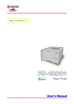
Page Printer
User’s Manual
Caution
NO LIABILITY IS ASSUMED FOR ANY DAMAGE CAUSED BY IMPROPER INSTALLATION.
Notice on Software
SOFTWARE USED WITH THIS PRINTER MUST SUPPORT THE PRINTER'S EMULATION MODE. The printer is factory-set to
emulate the PCL. The emulation mode can be changed by following the procedures described in Chapter 1.
Notice
The information in this manual is subject to change without notification. Additional pages may be inserted in future editions. The user
is asked to excuse any technical inaccuracies or typographical errors in the present edition.
No responsibility is assumed if accidents occur while the user is following the instructions in this manual. No responsibility is assumed
for defects in the printer's firmware (contents of its read-only memory).
This manual, any copyrightable subject matter sold or provided with or in connection with the sale of the page printer, are protected by
copyright. All rights are reserved. Copying or other reproduction of all or part of this manual, any copyrightable subject matter without
the prior written consent of Kyocera Corporation is prohibited. Any copies made of all or part of this manual, any copyrightable subject
must contain the same copyright notice as the material from which the copying is done.
Regarding Tradenames
PRESCRIBE is a registered trademark of Kyocera Corporation. PRESCRIBE 2e, KPDL, and KIR (Kyocera Image Refinement) are
trademarks of Kyocera Corporation.
Diablo 630 is a product of Xerox Corporation. IBM Proprinter X24E is a product of International Business Machines Corporation. Epson
LQ-850 is a product of Seiko Epson Corporation.
Hewlett-Packard, PCL, and PJL are registered trademarks of Hewlett-Packard Company. Centronics is a trade name of Centronics
Data Computer Corp. PostScript is a registered trademark of Adobe Systems Incorporated. Macintosh is a registered trademark of
Apple computer, Inc. Microsoft, Windows, and Windows NT are registered trademarks of Microsoft Corporation. PowerPC is a trademark of International Business Machines Corporation. ENERGY STAR is a U.S. registered mark. All other brand and product names
are registered trademarks or trademarks of their respective companies.
This Kyocera page printer uses PeerlessPrintXL to provide the HP LaserJet compatible PCL6 language emulation. PeerlessPrintXL
is a trademark of The Peerless Group, Redondo Beach, CA 90278, U.S.A.
This product was developed using the Tornado™ Real Time Operating System and Tools from Wind River Systems.
Contains UFST™ and MicroType® from Agfa Corporation.
© 2000 by Kyocera Corporation. All rights reserved, Revision 1.0., April 2000
i
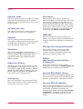
IBM PROGRAM LICENSE AGREEMENT
THE DEVICE YOU HAVE PURCHASED CONTAINS ONE OR MORE SOFTWARE PROGRAMS ("PROGRAMS") WHICH BELONG
TO INTERNATIONAL BUSINESS MACHINES CORPORATION ("IBM"). THIS DOCUMENT DEFINES THE TERMS AND CONDITIONS UNDER WHICH THE SOFTWARE IS BEING LICENSED TO YOU BY IBM. IF YOU DO NOT AGREE WITH THE TERMS
AND CONDITIONS OF THIS LICENSE, THEN WITHIN 14 DAYS AFTER YOUR ACQUISITION OF THE DEVICE YOU MAY
RETURN THE DEVICE FOR A FULL REFUND. IF YOU DO NOT SO RETURN THE DEVICE WITHIN THE 14 DAYS, THEN YOU
WILL BE ASSUMED TO HAVE AGREED TO THESE TERMS AND CONDITIONS.
The Programs are licensed not sold. IBM, or the applicable IBM country organization, grants you a license for the Programs only in the
country where you acquired the Programs. You obtain no rights other than those granted you under this license.
The term "Programs" means the original and all whole or partial copies of it, including modified copies or portions merged into other
programs. IBM retains title to the Programs. IBM owns, or has licensed from the owner, copyrights in the Programs.
1. License
Under this license, you may use the Programs only with the device on which they are installed and transfer possession of the Programs
and the device to another party.
If you transfer the Programs, you must transfer a copy of this license and any other documentation to the other party. Your license is
then terminated. The other party agrees to these terms and conditions by its first use of the Program.
You may not:
1) use, copy, modify, merge, or transfer copies of the Program except as provided in this license;
2) reverse assemble or reverse compile the Program; or
3) sublicense, rent, lease, or assign the Program.
2. Limited Warranty
The Programs are provided "AS IS."
THERE ARE NO OTHER WARRANTIES COVERING THE PROGRAMS (OR CONDITIONS), EXPRESS OR IMPLIED, INCLUDING, BUT NOT LIMITED TO, THE IMPLIED WARRANTIES OF MERCHANTABILITY AND FITNESS FOR A PARTICULAR PURPOSE.
Some jurisdictions do not allow the exclusion of implied warranties, so the above exclusion may not apply to you.
SUPPLEMENT TO AGREEMENT FOR SOFTWARE BUNDLING AND DISTRIBUTION FOR ALDC
3. Limitation of Remedies
IBM's entire liability under this license is the following;
1) For any claim (including fundamental breach), in any form, related in any way to this license, IBM's liability will be for actual
damages only and will be limited to the greater of:
a) the equivalent of U.S.$25,000 in your local currency; or
b) IBM's then generally available license fee for the Program
This limitation will not apply to claims for bodily injury or damages to real or tangible personal property for which IBM is legally liable.
IBM will not be liable for any lost profits, lost savings, or any incidental damages or other economic consequential damages, even if
IBM, or its authorized supplier, has been advised of the possibility of such damages. IBM will not be liable for any damages claimed by
you based on any third party claim. This limitation of remedies also applies to any developer of Programs supplied to IBM. IBM's and
the developer's limitations of remedies are not cumulative. Such developer is an intended beneficiary of this Section. Some jurisdictions
do not allow these limitations or exclusions, so they may not apply to you.
4. General
You may terminate your license at any time. IBM may terminate your license if you fail to comply with the terms and conditions of this
license. In either event, you must destroy all your copies of the Program. You are responsible for payment of any taxes, including
personal property taxes, resulting from this license. Neither party may bring an action, regardless of form, more than two years after
the cause of action arose. If you acquired the Program in the United States, this license is governed by the laws of the State of New York.
If you acquired the Program in Canada, this license is governed by the laws of the Province of Ontario. Otherwise, this license is
governed by the laws of the country in which you acquired the Program.
ii
Typeface Trademark Acknowledgement
All resident fonts in this printer are licensed from Agfa Corporation.
Helvetica, Palatino and Times are registered trademarks of Linotype-Hell AG.
ITC Avant Garde Gothic, ITC Bookman, ITC ZapfChancery and ITC Zapf Dingbats are registered trademarks of International Typeface Corporation.
Agfa Japan License Agreement Guidelines
1. “Software” shall mean the digitally encoded, machine readable, scalable outline data as encoded in a special format as well as the
UFST Software.
2. You agree to accept a non-exclusive license to use the Software to reproduce and display weights, styles and versions of letters,
numerals, characters and symbols (“Typefaces”) solely for your own customary business. Agfa Japan retains all rights, title and
interest to the Software and Typefaces and no rights are granted to you other than a License to use the Software on the terms
expressly set forth in this Agreement.
3. To protect proprietary rights of Agfa Japan, you agree to maintain the Software and other proprietary information concerning the
Typefaces in strict confidence and to establish reasonable procedures regulating access to and use of the Software and Typefaces.
4. You agree not to duplicate or copy the Software or Typefaces, except that you may make one backup copy.
5. This License shall continue until the last use of the Software and Typefaces, unless sooner terminated. This License may be
terminated by Agfa Japan if you fail to comply with the terms of this License and such failure is not remedied within thirty (30)
days after notice from Agfa Japan. When this License expires or is terminated, you shall either return to Agfa Japan or destroy all
copies of the Software and Typefaces and documentation as requested.
6. You agree that you will not modify, alter, disassemble, decrypt, reverse engineer or decompile the Software.
7. Agfa Japan warrants that for ninety (90) days after delivery, the Software will perform in accordance with Agfa Japan-published
specifications, Agfa Japan does not warrant that the Software is free from all bugs, errors and omissions.
THE PARTIES AGREE THAT ALL OTHER WARRANTIES, EXPRESSED OR IMPLIED, INCLUDING WARRANTIES OF FITNESS FOR A PARTICULAR PURPOSE AND MERCHANTABILITY, ARE EXCLUDED.
8. Your exclusive remedy and the sole liability of Agfa Japan in connection with the Software and Typefaces is repair or replacement
of defective parts, upon their return to Agfa Japan.
IN NO EVENT WILL AGFA JAPAN BE LIABLE FOR LOST PROFITS, LOST DATA, OR ANY OTHER INCIDENTAL OR CONSEQUENTIAL DAMAGES, OR ANY DAMAGES CAUSED BY ABUSE OR MISAPPLICATION OF THE SOFTWARE AND TYPEFACES.
9. New York, U.S.A. law governs this Agreement.
10. You shall not sublicense, sell, lease, or otherwise transfer the Software and/or Typefaces without the prior written consent of Agfa
Japan.
11. Use, duplication or disclosure by the Government is subject to restrictions as set forth in the Rights in Technical Data and Computer
Software clause at FAR 252-227-7013, subdivision (b)(3)(ii) or subparagraph (c)(1)(ii), as appropriate. Further use, duplication or
disclosure is subject to restrictions applicable to restricted rights software as set forth in FAR 52.227-19 (c)(2).
12. YOU ACKNOWLEDGE THAT YOU HAVE READ THIS AGREEMENT, UNDERSTAND IT, AND AGREE TO BE BOUND BY ITS
TERMS AND CONDITIONS. NEITHER PARTY SHALL BE BOUND BY ANY STATEMENT OR REPRESENTATION NOT
CONTAINED IN THIS AGREEMENT. NO CHANGE IN THIS AGREEMENT IS EFFECTIVE UNLESS WRITTEN AND
SIGNED BY PROPERLY AUTHORIZED REPRESENTATIVES OF EACH PARTY.
iii
Contents
Contents
Introduction ................................................................................................vii
Features ........................................................................................................................................................ viii
Options ............................................................................................................................................................. x
Guide to the Manuals ..................................................................................................................................... xi
Guide to the User's Manual .......................................................................................................................... xii
Chapter 1
Basic Settings and Operations............................................... 1-1
1.1 Operator Panel ....................................................................................................................................... 1-2
1.1.1 Indicators...................................................................................................................................... 1-3
1.1.2 Keys............................................................................................................................................... 1-3
1.2 Remote Operation Panel Utility ........................................................................................................... 1-6
1.2.1 Requirements ............................................................................................................................... 1-6
1.2.2 Installing the Remote Operation Panel ...................................................................................... 1-6
1.3 Configuring the Printer ....................................................................................................................... 1-10
1.3.1 Basic Settings for the Remote Operation Panel ....................................................................... 1-10
1.3.2 Connecting the Remote Operation Panel Utility to the Printer .............................................. 1-13
1.3.3 Menu Items................................................................................................................................. 1-14
1.4 Paper..................................................................................................................................................... 1-15
1.4.1 Number of Copies to be Printed ................................................................................................ 1-15
1.4.2 Page Orientation ........................................................................................................................ 1-16
1.4.3 Paper Source............................................................................................................................... 1-17
1.4.4 Paper Size ................................................................................................................................... 1-18
1.4.5 Paper Type Settings for Paper Sources ..................................................................................... 1-20
1.4.6 Paper Source Properties ............................................................................................................ 1-22
1.5 Printer Environment ........................................................................................................................... 1-23
1.5.1 Print Density .............................................................................................................................. 1-23
1.5.2 KIR.............................................................................................................................................. 1-25
1.5.3 Ecoprint ...................................................................................................................................... 1-26
1.5.4 Resolution ................................................................................................................................... 1-27
1.5.5 Form Feed Timeout .................................................................................................................... 1-28
1.5.6 Sleep Timer ................................................................................................................................ 1-29
1.5.7 Emulation ................................................................................................................................... 1-30
1.5.8 Serial Interface Parameters ...................................................................................................... 1-32
1.5.9 Network Board Properties ......................................................................................................... 1-34
1.5.10 RAM disk .................................................................................................................................. 1-35
1.5.11 Remote Operation Panel Display Language........................................................................... 1-37
iv
Contents
1.6 Other Settings..................................................................................................................................... 1-39
1.6.1 Printer Properties ...................................................................................................................... 1-39
1.6.2 Password for the Printer............................................................................................................ 1-41
1.6.3 Printer Memory Status .............................................................................................................. 1-44
1.6.4 Host buffer.................................................................................................................................. 1-45
1.6.5 Adding a Name and Description to the Printer........................................................................ 1-47
1.6.6 Displaying the Resource List..................................................................................................... 1-48
1.6.7 Sending PRESCRIBE Commands to the Printer .................................................................... 1-49
Chapter 2
Printer Driver........................................................................... 2-1
2.1 Installing the Printer Driver for Windows 95/98 ................................................................................. 2-2
2.1.1 Installing the Printer Driver ....................................................................................................... 2-2
2.2 Printing From Applications................................................................................................................... 2-3
2.2.1 Feeding from the MP tray............................................................................................................ 2-5
2.2.2 Custom Size Settings ................................................................................................................... 2-6
Chapter 3
Maintenance ........................................................................... 3-1
3.1 Toner Container Replacement .............................................................................................................. 3-2
3.1.1 Toner Container Replacement Interval ...................................................................................... 3-2
3.1.2 Replenishing Toner ...................................................................................................................... 3-3
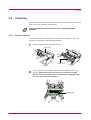
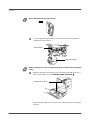
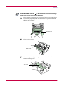
3.2 Cleaning ................................................................................................................................................. 3-6
3.2.1 Printer Interior............................................................................................................................. 3-6
Chapter 4
Troubleshooting ...................................................................... 4-1
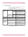
4.1 General Guide ........................................................................................................................................ 4-2
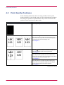
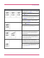
4.2 Print Quality Problems ......................................................................................................................... 4-3
4.3 Indicators ............................................................................................................................................... 4-5
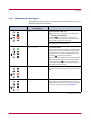
4.3.1 Maintenance Messages ................................................................................................................ 4-6
4.3.2 Errors Requiring Service Personnel Attention........................................................................... 4-8
4.3.3 Error Messages........................................................................................................................... 4-11
4.3.4 Normal Indicator Display .......................................................................................................... 4-12
4.4 Correcting a Paper Jam....................................................................................................................... 4-13
4.4.1 Jam at the Face-down and Face-up Trays ................................................................................ 4-13
4.4.2 Jam at the Paper Cassette......................................................................................................... 4-14
4.4.3 Jam Inside the Printer............................................................................................................... 4-14
v
Contents
Chapter 5
Paper Selection....................................................................... 5-1
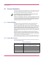
5.1 General Guidelines ................................................................................................................................ 5-2
5.1.1 Paper Availability......................................................................................................................... 5-2
5.1.2 Paper Specifications ..................................................................................................................... 5-2
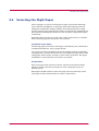
5.2 Selecting the Right Paper...................................................................................................................... 5-3
5.3 Special Paper.......................................................................................................................................... 5-7
5.3.1 Transparency (overhead projection film) .................................................................................... 5-7
5.3.2 Adhesive-Backed Labels .............................................................................................................. 5-8
Appendix A
Fonts ....................................................................................... A-1
A.1 Internal Fonts........................................................................................................................................A-2
A.2 List of Fonts ...........................................................................................................................................A-3
A.2.1 Internal Scalable and Bitmap Fonts ..........................................................................................A-3
Appendix B
Expansion Memory Installation .............................................. B-1
Appendix C
Host Computer Interface........................................................ C-1
C.1 Parallel Interface...................................................................................................................................C-2
C.1.1 Parallel Interface Communication Modes ..................................................................................C-2
C.1.2 Interface Signals..........................................................................................................................C-2
C.2 Serial Interface (Option) .......................................................................................................................C-6
C.2.1 RS-232C Interface .......................................................................................................................C-6
C.2.2 RS-422A Interface .......................................................................................................................C-7
C.3 RS-232C/RS-422A Protocol ...................................................................................................................C-9
C.3.1 PRESCRIBE FRPO D0 Command ...........................................................................................C-10
C.4 RS-232C Cable Connection.................................................................................................................C-11
C.4.1 Obtain a Suitable RS-232C Cable ............................................................................................C-11
C.4.2 Connecting the Printer to the Computer .................................................................................C-11
Appendix D
Printer Specifications ............................................................. D-1
Appendix E
Glossary .................................................................................. E-1
Index .................................................................................................. Index-1
vi
Introduction
The Kyocera Mita page printer has many extremely desirable features. It was designed to
make a contribution to a cleaner environment as well as to represent the latest generation of
page printer technology.
This section explains the following topics:
•
•
•
•
Features
Options
Guide to the Manuals
Guide to the User's Manual
vii
Features
Long Life Modules
The main modules in this laser printer such as the drum, developer unit,
and fuser unit have been designed for long life.
Environmentally Benign Waste Parts
The toner container is made out of a benign, flammable material. (Be sure
to dispose of containers according to local laws and regulations.)
Sleep Mode
Conserves energy during the printer's idle periods.
Ecoprint
Extends the toner yield by reducing the amount of toner used on the page.
Standard Bi-directional Parallel Interface
Supports high-speed data exchange with the computer.
Wide Variety of Available Fonts
The printer comes with 45 PCL-compatible fonts and a line printer bitmap
font installed.
PRESCRIBE Command Language
PRESCRIBE provides features including advanced graphics capabilities
that allow you to print any conceivable outline shape or solid form. Also
provided are a variety of special effects, such as patterned fills, gray-scale
shading, a user-accessible print image model, and multiple page
orientations and print directions within the same page.
PDF417 Two-dimensional Bar Code
The printer includes a capability that allows the user to implement twodimensional stacked bar code symbology PDF417 (Portable Data File 417).
Simple Network Management Protocol (SNMP) Compliance
The printer supports SNMP and can be used as a network printer.
Kyocera Mita PrintMonitor Utility
Provides network wide management of the printers. Refer to the readme
file located in the Kyocera Mita Digital Library CD-ROM (supplied with
the printer) for details.
viii
Remote Operation Panel Utility
This software displays a virtual operator panel on the computer connected
to the printer either locally (through a parallel or serial interface) or over a
network. You can use this utility to monitor the printer's basic settings and
conditions on Windows 95/98 or Windows NT 4.0 operating systems. The
Remote Operation Panel utility is provided on the Kyocera Mita Digital
Library CD-ROM supplied with the printer.
ix
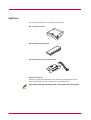
Options
The following options are available for the printer:
PF-17 Paper Feeder
PK-6 KPDL2 Upgrade Kit
IB-10E Serial Interface Board Kit
Network Boards
Contact your Kyocera Mita dealer for purchasing information on the
network board that is best suited for use with this printer.
Only network boards operating on DC 3.3V can be used in this printer.
Caution
x
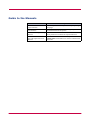
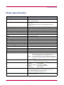
Guide to the Manuals
Item
Description
Installation Manual
(paper manual)
Describes procedures from printer setup to printing a
test page.
User's Manual
(this manual)
Guides you through topics concerning the operations
and maintenance of the printer.
PRESCRIBE Programming
Manual
Describes how to use the PRESCRIBE commands and
their parameters in detail for experienced users.
PDF417 Two-Dimensional
Bar Code Implementation
Manual
Includes a PDF417 overview and explains
PRESCRIBE commands for use with two-dimensional
barcodes.
xi
Guide to the User's Manual
This User's Manual guides you through the following topics:
Chapter 1
Basic Settings and Operations
This chapter describes the names and functions of the keys and indicators
on top of the printer. Further, it explains how to make printer settings
using the Remote Operation Panel utility contained on the Kyocera Mita
Digital Library CD-ROM supplied with the printer.
Chapter 2
Printer Driver
This chapter explains how to install the printer driver, and how to print
from applications.
Chapter 3
Maintenance
This chapter explains how to replace the toner container and how to care
for your printer.
Chapter 4
Troubleshooting
This chapter explains how to handle printer problems that may occur, such
as paper jams.
Chapter 5
Paper Selection
This chapter explains the types of paper that can be used with the printer.
Appendix A
Fonts
This appendix explains about and lists the printer's internal fonts.
Appendix B
Expansion Memory Installation
This appendix explains how to expand the printer's memory.
Appendix C
Host Computer Interface
This appendix describes the pin assignment and specifications for the
printer's parallel interface and optional serial interface.
Appendix D
Printer Specifications
This appendix lists the printer's specifications.
Appendix E Glossary
This appendix explains the terminology used in this manual.
xii
Chapter 1
Basic Settings and
Operations
1
This chapter explains the following topics:
•
•
•
•
•
•
Operator Panel
Remote Operation Panel Utility
Configuring the Printer
Paper
Printer Environment
Other Settings
1-1
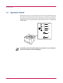
Operator Panel
1.1
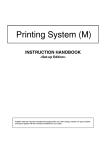
Operator Panel
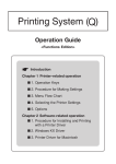
The operator panel on top of the printer consists of four indicators and two
keys. The four indicators light, flash, and go off in combination, indicating
the printer's status. The keys perform operations, such as canceling data,
switching the printer mode between online and offline status, and printing
status pages.
1
2
3
4
5
6
The numbers used in the above figure are referred to in the "Reference"
column of the table on the following page.
Note
1-2
Operator Panel
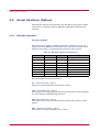
1.1.1
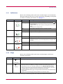
Indicators
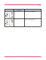
Refer to the following table for the name and description of each indicator.
The same indicator can have a variety of meanings, depending on the speed
at which it is flashing. For details, see Chapter 4.
Reference
Name
1
Online
indicator
Status
Lit
Indicates online status (printing is possible).
Flashing
• An error has occurred, but printing resumes when the
key is pressed.
• Offline status. You cannot print, but the printer can receive
data.
• The printer is in sleep mode.
Off
Printing has stopped because an error has occurred.
Lit
The printer is processing data.
Flashing
The printer is receiving data.
(Green)
2
Data
indicator
Meaning
(Green)
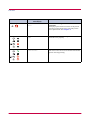
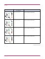
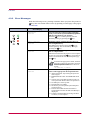
3
4
Attention
indicator
Lit
The printer cover is open.
Flashing
• A paper jam has occurred.
• The paper cassette is not inserted properly or the paper has
run out.
(Red)
Off
The printer status is normal.
Toner
indicator
Lit
The printer has stopped because the toner is exhausted.
Flashing
The toner is running low.
(Red)
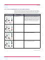
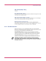
1.1.2
Keys
Refer to the following table for the name and description of the basic
functions of each key.
Reference
5
Name
Function
key
Cancels printing in progress when pressed for 1 second or more.
(Cancel key)
6
key
(Go key)
• Switches between online and offline when pressed for less than 3 seconds.
• Switches between the MP tray and paper cassette when the paper runs out.
• Depending on the error message displayed on the Remote Operation Panel,
there are cases where operation will continue after pressing this key. If such a
message appears, operation resumes when this key is pressed.
• Prints a standard status page* when pressed for 3 seconds or more and less than
10 seconds.
• Prints a service status page when pressed for 10 seconds or more.
*: For a full description of the standard status page, see the next page. The service status page is used for service purposes.
1-3
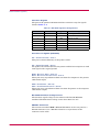
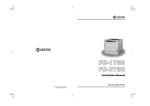
Operator Panel
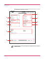
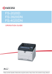
The following is the printout of a typical standard status page. Its contents
are explained in detail on the next page.
1
2
4
3
5
7
6
8
9
Items and values on the status page may vary depending on the printer's
firmware version.
Note
1-4
Operator Panel
1 — Software Version
This information shows the software (firmware) version and date of issue
of the printer.
2 — Hardware Information
This information shows the currently selected paper source (indicated by
an asterisk), paper size, and various other printer settings.
3 — Page Information
This information shows the currently selected resolution, number of copies
printed to date, and the total page count.
4 — Memory
This information shows the amount of total memory installed in the
printer, the amount of currently available memory, and the current status
of the RAM disk (see page 1-35).
5 — Installation Options
This shows the option(s) currently installed in the printer.
6 — Emulation
This shows all available emulations and the currently selected emulation
(marked with an asterisk). The printer is shipped from the factory with
PCL 6 emulation selected.
7 — Error Log
This displays the last three instances of the following four types of errors,
listing them in the order of their occurrence: KPDL Error Press GO;
Memory overflow Press GO; Print overrun Press GO; RAM DISK
err Press GO. The most recent error is displayed on the top line of the
Error Log. For error remedies, see section 4.3.3. Error information is
cleared when the printer's power is turned off.
8 — Interface Information
This information shows all interfaces installed in the printer and the
currently selected interface (marked with an asterisk).
The Font section shows the font that is automatically selected when the
printer starts up (default font). It is possible to set different default fonts
for each interface.
9 — KIR Test Pattern
This shows the KIR test pattern. You can confirm whether KIR is on or off.
1-5
Remote Operation Panel Utility
1.2
Remote Operation Panel Utility
The Remote Operation Panel utility is provided on the Kyocera Mita
Digital Library CD-ROM supplied with the printer. You can install the
Remote Operation Panel on a computer that runs under Windows 95/98 or
Windows NT 4.0 operating systems, and use it to change basic printer
settings, monitor the current printer status, and display error messages
(such as paper jam warnings) on the computer screen.
1.2.1
Requirements
The Remote Operation Panel utility is designed to run under Windows 95/98
or Windows NT 4.0 operating systems. With Windows 95/98 it can be used
with either local (parallel or serial) or network (TCP/IP or IPX/SPX)
connection. With Windows NT 4.0 it can only be used over a network.
Note
1.2.2
•
The Remote Operation Panel utility does not run under any other
operating systems.
•
The Remote Operation Panel utility provided on the Kyocera Mita
Digital Library CD-ROM supplied with the printer is for use only with
the Kyocera Mita FS-1000+ XL printer driver. Printing problems may
occur if it is used in combination with any other printer driver.
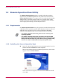
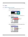
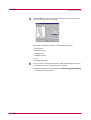
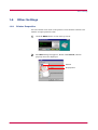
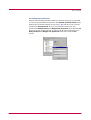
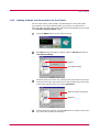
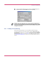
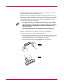
Installing the Remote Operation Panel
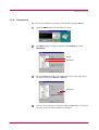
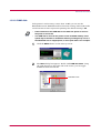
1
Insert the Kyocera Mita Digital Library CD-ROM supplied with the
printer into the CD-ROM drive of the computer.
After a few moments, the Kyocera Mita Digital Library main menu
appears. Click on Printer Utilities.
If this screen does not appear, click the Windows Start button and
select Run.
1-6
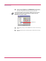
Remote Operation Panel Utility
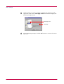
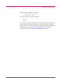
Enter the following:
[CD drive letter]:\setup
Click the OK button. The Kyocera Mita Digital Library main menu
appears.
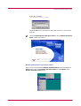
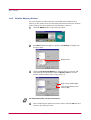
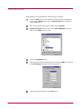
2
Click on Install Remote Operation Panel to start Remote Operation
Panel utility installation.
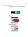
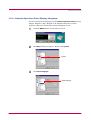
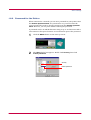
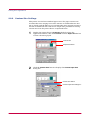
Starting the Remote Operation Panel
Once you have installed the Remote Operation Panel, click the Windows
Start button, then click Remote Operation Panel from Programs. The
Remote Operation Panel starts.
1-7
Remote Operation Panel Utility
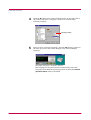
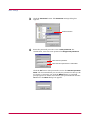
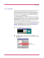
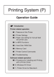
Remote Operation Panel Start-up Screen
6
7
1
2
8
3
4
5
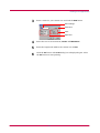
Functions of the Remote Operation Panel Utility
The following table explains the names and function of the parts of the
Remote Operation Panel utility.
Note
Reference
1
The numbers appearing in the figure are referred to in the "Number"
column of the table below.
•
The explanations of messages appearing in this manual are based on
the premise that the printer is used over a network. Accordingly, the
explanations include some messages that do not appear when the
printer is used locally.
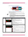
Name
Function
Message display
The printer status is displayed on the upper line (1) and the following
information is displayed on the lower lines.
(2) Active interface
PAR: Standard bi-directional parallel interface
SER: Optional serial interface (RS-232C/422A)
OPT: Optional network interface
(3) Resolution
300: 300 dpi
600: 600 dpi (default)
(4) Paper size of the currently selected paper cassette
(5) Number of copies to be printed
When an error occurs, details of the error are displayed on the upper
and lower lines.
(1)
(2)
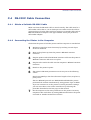
2
•
(3) (4) (5)
Displays a suitable icon according to the printer's status.
: The printer is ready to print.
: The paper is exhausted or the cassette is not installed
properly. Load more paper or close the cassette properly.
: A paper jam has occurred. Refer to section 4.4 and remove the
jammed paper.
: Toner is running low or is exhausted. Replace with a new
toner container. See section 3.1
: An error has occurred. Refer to the message displayed. See
section 4.3
(Continued on next page)
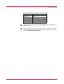
1-8
Remote Operation Panel Utility
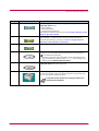
Number
Name
Function
3
SET UP button
This allows you to make the following basic settings for the Remote
Operation Panel utility:
• Status polling
• Error notification
• Virtual printer animation
For details on these settings, see section 1.3.1 Basic Settings for the
Remote Operation Panel.
4
CONNECT button
This allows you to select the type of connection between the printer and
the computer — either local (via serial or parallel interface) or
network. For details, see section 1.3.2 Connecting the Remote
Operation Panel Utility to the Printer.
5
HELP button
Displays help messages.
6
GO button
This button appears only when the printer is connected to the
computer via a network. It has the same function as the printer's
key and does the following:
• Switches the printer online and offline, prints and feeds out one
page, and continues printing when Press GO error messages are
displayed on the Remote Operation Panel.
7
MENU button
This is used to change various printer settings from the Remote
Operation Panel utility. See page 1-14.
8
Printer image
This virtual printer animation graphically indicates the printer's
status. For example, when you open the printer's top cover, the top
cover on the printer image also opens.
It may take several minutes for a change in status to be
reflected in the animation.
Note
1-9
Configuring the Printer
1.3
Configuring the Printer
This section explains how to set and confirm the printer's configuration
from the Remote Operation Panel utility. The value set from the Remote
Operation Panel utility becomes the printer's default setting. However,
when printing, the printer may automatically switch to another setting,
depending on the application software or printer driver settings.
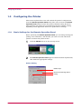
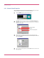
1.3.1
Basic Settings for the Remote Operation Panel
Before operating the Remote Operation Panel, you can change settings for
polling, error notification, and whether you want to use the 3D virtual
printer to monitor the printer status.
1
Click the SETUP button on the start-up screen.
2
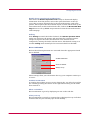
The Remote Operation Panel appears. Read the follow explanations,
then make the appropriate settings.
Status Polling
Enable Traps
Browse NIC Web Page button
Polling
1-10
Configuring the Printer
Enable Traps (unsolicited notifications)
This allows the Remote Operation Panel utility to obtain and display
information about the printer, such as the open/closed state of the top
cover, that is output automatically by the network interface card in the
printer. This requires that the network output of status information by the
network interface card be enabled. To do this, click on the Browse NIC Web
Page button to call up SNMP trap notification from the network interface
card homepage.
Polling
With Polling activated (check box checked), the Remote Operation Panel
utility logs itself onto the printer and automatically recognizes printer
changes at regular intervals. This duration of the interval can be
configured by moving the slider with the mouse. The default setting is 15
seconds. Polling must normally be left activated (check box checked).
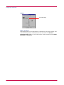
Error notification
Each of the following functions are activated when the appropriate check
box is checked.
Audible Notification
Show on Taskbar
Always on top
These settings allow you to determine the way your computer notifies you
of errors:
Audible Notification
A sound is played when an error occurs. Specify the .wav file to be used for
the sound by pressing the button on the right and browsing for the folder
that contains it.
Show on Taskbar
Error notification is given by displaying an icon on the task bar.
Always on top
Error notification is given by a message that is displayed on top of all other
windows that may be currently open on the desktop.
1-11
Configuring the Printer
Image
Show 3D image
Show 3D image
This displays the 3D virtual printer for monitoring the printer status. You
can select the position of the animation in reference to the Remote
Operation Panel utility, as well as the motion of the animation from Static,
Rotating, and Random.
1-12
Configuring the Printer
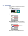
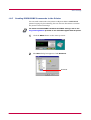
1.3.2
Connecting the Remote Operation Panel Utility to the Printer
The Remote Operation Panel utility can be used whenever the printer is
connected to the computer via the parallel or serial interface or through a
network interface (TCP/IP or IPX/SPX). To establish the connection to the
printer, proceed as follows:
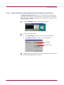
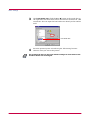
1
Click the CONNECT button on the start-up screen.
2
On the connection wizard:
a. Click Local Printer to connect to a locally attached printer.
b. Click Network Printer to connect to a network printer.
Local Printer
Network Printer
3
Depending on the connection type you have chosen above, follow the
instructions displayed by the wizard.
1-13
Configuring the Printer
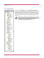
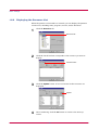
1.3.3
Menu Items
When you click the MENU button on the Remote Operation Panel
utility, the printer menu as shown on the left appears. (This screen is an
example only, and the entire menu is not actually displayed.) You can
display current settings by clicking each item. The contents displayed
will vary depending on the optional devices installed and whether the
connection is through a network or local (through a parallel or serial
interface).
Note
If you have set a password for the Remote Operation Panel
utility, a password prompt appears. Enter your password and
click the OK button. The Menu dialog box appears.
For details on passwords, see page 1-41.
1-14
Paper
1.4
Paper
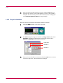
1.4.1
Number of Copies to be Printed
This sets the number of copies to be printed. The value set becomes the
default for the current interface. The default setting is 1.
1
Click the MENU button on the start-up screen.
2
The Menu dialog box is displayed. Double click Page control, then
click Copy count.
Page control
Copy count
3
Click the ! or " button in the combo box on the right, or directly
input the number of copies you want to set in the combo box. You can
make settings up to 999.
Copy count
1-15
Paper
4
1.4.2
After you have input the number of copies, click the OK button to
return to the start-up screen. The number of copies to be printed is
changed. After the setting is made, the number you set is displayed
on the Remote Operation Panel's message display.
Page Orientation
This sets the page orientation. The default setting is Portrait.
1
Click the MENU button on the start-up screen.
2
The Menu dialog box appears. Double click Page control, then click
Orientation. Using the radio buttons on the right, select either
Portrait or Landscape as the page orientation.
Page control
Orientation
Orientation
3
After you have selected the orientation, click the OK button to return
to the start-up screen. The orientation is changed.
1-16
Paper
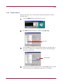
1.4.3
Paper Source
This sets the paper source. The default setting is the printer's cassette
(Internal Tray).
1
Click the MENU button on the start-up screen.
2
The Menu dialog box appears. Double click Input Tray.
Input Tray
3
Click the " button next to the pull-down menu on the right side of
the screen to display the available paper sources. Select the paper
source you want to set.
Current Feeder
4
After you have selected a paper source, click the OK button to return
to the start-up screen. The default paper source is changed.
1-17
Paper
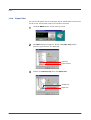
1.4.4
Paper Size
You can set the paper size for each paper source. The default is Letter size
for the U.S.A. and Canada, and A4 for all other countries.
1
Click the MENU button on the start-up screen.
2
The Menu dialog box appears. Double click Input Tray and the
printer's paper sources are displayed.
Input Tray
Paper Sources
3
Double click Internal Tray, then click Paper Size.
Internal Tray
Paper Size
1-18
Paper
4
Click the " button next to the pull-down menu on the right side of
the screen to display the available paper sizes. Select the paper size
you want to set. For paper sizes that can be fed from the printer, see
Chapter 5.
Paper Size
5
To set the paper size for the MP Tray, double click MP Tray and
repeat the above procedure.
6
After you have selected a paper size, click the OK button to return to
the start-up screen. The new paper size is set for the paper source.
1-19
Paper
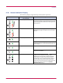
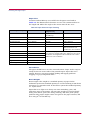
1.4.5
Paper Type Settings for Paper Sources
You can select the paper type (thickness) of thick, normal, or thin for each
paper source. The default setting is normal.
1
Click the MENU button on the start-up screen.
2
The Menu dialog box appears. Double click Input Tray and the
printer's paper source is displayed.
Input Tray
Paper Sources
3
Double click Internal Tray and Detail in that order, then click Paper
Type.
Internal Tray
Detail
Paper Type
1-20
Paper
4
Click the " button next to the pull-down menu on the right side of
the screen. Select a paper thickness from Normal, Thick, and Thin.
Paper type
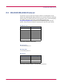
Refer to the following table for standard paper weight settings:
Paper thickness setting
Corresponding paper weight
Thin
Less than 64 g/m2
Normal (default setting)
64 to 90 g/m2 Transparency
(MP Tray only)
Thick
Greater than 90 g/m2
Envelope (64 to 90 g/m2) [MP Tray only]
5
To make the paper thickness settings for the MP Tray, double click
MP Tray and repeat the above procedure.
6
After you have selected a paper thickness, click the OK button to
return to the start-up screen. The paper source paper thickness
settings are changed.
1-21
Paper
1.4.6
Paper Source Properties
You can display information about the paper source, such as whether paper
is loaded and the maximum paper capacity.
1
Click the MENU button on the start-up screen.
2
The Menu dialog box appears. Double click Input Tray. The printer's
paper sources are displayed. If the optional paper feeder is installed,
PF-17 is displayed under Internal Tray.
Input Tray
Paper Sources
3
Click the paper source whose properties you wish to confirm.
Indicates whether the paper
source is empty or not.
The maximum number of pages
the paper source can
accommodate.
1-22
Printer Environment
1.5
Printer Environment
1.5.1
Print Density
You can set the print density for each paper source. You can choose between
five levels of density where 1 is the lightest and 5 is the darkest. The
default setting is 3.
1
Click the MENU button on the start-up screen.
2
The Menu dialog box appears. Double click Input Tray and the
printer's paper source is displayed.
Input Tray
1-23
Printer Environment
3
Double click Internal Tray and Detail in that order, then click Density.
Use the mouse to move the slider on the right side of the screen to
the left (light) and right (dark).
Internal Tray
Slider
Light
Dark
Density
Detail
4
To set the density for the MP Tray, double click MP Tray and repeat
the above procedure.
5
After you have selected the density, click the OK button to return to
the start-up screen. The paper source print density setting is
changed.
1-24
Printer Environment
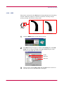
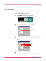
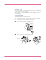
1.5.2
KIR
This printer incorporates the KIR (Kyocera Image Refinement) smoothing
function. KIR uses software to enhance resolution, resulting in highquality printing. The default setting is On.
Q
With KIR Off
With KIR On
1
Click the MENU button on the start-up screen.
2
The Menu dialog box appears. Double click Quality, then click KIR
mode. You can toggle the KIR mode On and Off using the radio
buttons on the right side of the screen.
Quality
KIR mode
KIR mode
3
After you have selected On or Off, click the OK button to return to
the start-up screen. The KIR mode is changed.
1-25
Printer Environment
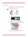
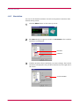
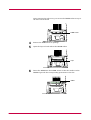
1.5.3
Ecoprint
Ecoprint allows you to reduce the amount of toner used, so that you can
save on printing costs. You can set Ecoprint mode On as follows. The
default setting is Off.
Ecoprint does not effect printing speed.
Note
With Ecoprint Off
(default)
With Ecoprint On
1
Click the MENU button on the start-up screen.
2
The Menu dialog box appears. Double click Quality, then click
Ecoprint. You can toggle the Ecoprint mode On and Off using the
radio buttons on the right side of the screen.
Quality
Ecoprint
Ecoprint
3
After you have selected On or Off, click the OK button to return to
the start-up screen. The Ecoprint mode is changed.
1-26
Printer Environment
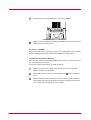
1.5.4
Resolution
You can set the resolution for printing. The default setting is 600 dpi.
1
Click the MENU button on the start-up screen.
2
The Menu dialog box appears. Double click Quality, then click
Resolution.
Quality
Resolution
3
Press the " button next to the pull-down menu on the right side of
the screen, and select 600 dpi or 300 dpi.
Resolution
4
After you have selected a resolution, click the OK button to return to
the start-up screen. The resolution is changed.
1-27
Printer Environment
1.5.5
Form Feed Timeout
You can set the amount of time before the last page automatically prints
when print data ends without end of page information. The default setting
is 30 seconds.
1
Click the MENU button on the start-up screen.
2
The Menu dialog box appears. Double click System.
System
3
Click Form feed timeout. Use the mouse to move the slider on the
right side of the screen to the left or right. You can set the time in 5second intervals from 0 to 495 seconds. To disable form feed timeout,
set the time to 0.
Form feed timeout
Slider
4
After you have set a time, click on the OK button to return to the
start-up screen. The form feed timeout time is changed.
1-28
Printer Environment
1.5.6
Sleep Timer
The printer has a sleep timer to conserve power when the printer is not
printing, processing, or receiving data. You can adjust the timer value; that
is, the amount of time before the printer enters sleep mode in the absence
of data. The default setting is 5 minutes.
1
Click the MENU button on the start-up screen.
2
The Menu dialog box appears. Double click System.
System
3
Click Sleep time. Use the mouse to move the slider on the right side
of the screen to the left or right. You can set the time in 5-minute
intervals from 0 to 120 minutes. To turn the sleep timer off, set the
time to 0.
Sleep time
Slider
4
After you have set the time, click the OK button to return to the
start-up screen. The time interval for the sleep timer is changed.
1-29
Printer Environment
1.5.7
Emulation
You can set the default emulation for each of the printer's interfaces. The
default setting is PCL.
1
Click the MENU button on the start-up screen.
2
The Menu dialog box appears. Double click Emulation. The available
interfaces are displayed.
Emulation
Interfaces
3
Click the interface whose emulation you want to change. The current
emulation is displayed in the pull-down menu box on the right side of
the screen.
Current emulation
1-30
Printer Environment
4
Click the " button next to the pull-down menu on the right side of
the screen, and select an emulation.
The printer emulates operation of the following printers:
• Line printer
• IBM Proprinter
• DIABLO 630
• EPSON LQ-850
• PCL
• KPDL2 (Optional*)
5
After you have selected an emulation, click the OK button to return
to the start-up screen. The emulation is changed.
*:KPDL2 is displayed only if the optional KPDL2 Upgrade Kit [PK-6]
is installed on your printer.
1-31
Printer Environment
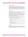
1.5.8
Serial Interface Parameters
This setting is only available if you have the optional Serial Interface Kit
(IB-10E) installed on your printer. You can change the baud rate, data bits,
stop bit, parity, and flow control for the serial interface. If these settings
are changed, you must also change the serial interface parameters on your
computer.
1
Click the MENU button on the start-up screen.
2
The Menu dialog box appears. Double click Interface settings and
Serial in that order. The serial interface items are displayed on the
screen.
Interface settings
Serial
Serial interface items
3
Click the item you want to change, then select the value you want to
set from the pull-down menu.
Baud rate
1-32
Printer Environment
The following table contains default value settings:
Parameter
Default value
Baud rate
9600
Data bits
8
Stop bit
1
Parity
None
Flow control
DTR, positive, and XON
4
After you have made settings, click the OK button to return to the
start-up screen.
5
After making the above changes, change the corresponding settings
for the serial interface on the computer. Once changes are complete,
start the Remote Operation Panel.
1-33
Printer Environment
1.5.9
Network Board Properties
You can display information about the network board, such as its version
and serial number, model name, and network addresses.
1
Click the MENU button on the start-up screen.
2
The Menu dialog box appears. Double click Interface settings and
Network in that order. The network board properties are displayed
as shown in the figure.
Interface settings
Network
Network board properties
3
Click on an item to display its contents on the right side of the
screen. The example below shows the screen that appears when you
click on IP address.
4
After confirming the properties, click the OK button to return to the
start-up screen.
1-34
Printer Environment
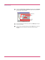
1.5.10 RAM disk
If the printer's total memory is more than 12 MB, you can use the
RAM disk function. RAM disk enables electronic sorting, which reduces the
overall amount of time required for printing. The default setting is Off.
Note
•
Data contained on the RAM disk is lost when the printer is reset or
the power is turned off.
•
The RAM disk is set from the printer's user available memory. Print
speed may be slowed or insufficient memory warnings may occur, if
the RAM disk size is inappropriate, or if the print data is too complex.
1
Click the MENU button on the start-up screen.
2
The Menu dialog box appears. Double click RAM disk mode. Using
the radio buttons on the right side of the screen, you can toggle
RAM disk mode On and Off.
RAM disk mode
1-35
Printer Environment
3
Note
Set the size of the RAM disk. Click RAM disk size. Set the size by
clicking the ! and " buttons in the combo box on the right side of
the screen, or input the value directly into the combo box.
The maximum RAM disk value should be 9 MB less than the printer's
total memory. (If the printer's total memory is 21 MB or more, the
RAM disk size is fixed to 12 MB.)
RAM disk size
4
After making settings, click the OK button to return to the start-up
screen.
5
Turn the printer's power off and on again to make the new setting
effective.
1-36
Printer Environment
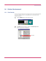
1.5.11 Remote Operation Panel Display Language
You can select from six languages for the Remote Operation Panel message
display: English (U.S.A), English (U.K), English (Australia), French,
German, and Italian. The default setting is English (U.S.A).
1
Click the MENU button on the start-up screen.
2
The Menu dialog box appears. Double click System.
System
3
Click Panel language.
Panel language
1-37
Printer Environment
4
Click the " button next to the pull-down menu on the right side of
the screen, and select a language. (German is selected in the
following example.)
Message display
5
After you have selected a language, click the OK button to return to
the start-up screen. The screen changes to the selected display
language.
The display language is changed to German.
The language on the panel buttons automatically reflect the
language of the Windows operating system on which the Remote
Operation Panel utility is installed.
1-38
Other Settings
1.6
1.6.1
Other Settings
Printer Properties
You can confirm items such as the printer's serial number and the total
number of copies printed to date.
1
Click the MENU button on the start-up screen.
2
The Menu dialog box appears. Double click General, and the
property items are displayed.
General
Property items
1-39
Other Settings
3
Click the item you want to confirm to display the contents on the
right side of the screen. Total page count was clicked to display the
following sample screen.
Total page count
Total page
4
After confirming settings, click the OK button to return to the startup screen.
1-40
Other Settings
1.6.2
Password for the Printer
When connected to a network, you can set a password for your printer from
the Remote Operation Panel. If a password is set, you must enter the
correct password in order to change settings from the Remote Operation
Panel. However, you can print without entering the password.
A password can be an ASCII character string of up to 15 characters and is
case-sensitive. The space character is not allowed as part of the password.
1
Click the MENU button on the start-up screen.
2
The Menu dialog box appears. Double click Security, then click
Printer password.
Security
Printer password
1-41
Other Settings
3
Click the Password button. The Password settings dialog box
appears.
Password button
4
Enter the password you want to set in New password. For
confirmation, enter the same password in Retype new password.
Enter the new password.
Enter the same password for confirmation.
Click the OK button. The password is set for the Remote Operation
Panel. We recommend that you record your password so that you do
not forget it. Next time you click the MENU button, a password
prompt appears as shown below. Enter your password and click the
OK button. The Menu dialog box appears.
1-42
Other Settings
To Change the Password
Perform the following procedure when you want to change your password
or remove the password function from the Remote Operation Panel utility.
Display the password settings screen (page 1-42) and enter your current
password in Old password. To set a new password, enter your new
password in New password and Retype new password, then click the OK
button to set the new password. To remove the password function, leave
New password and Retype new password blank, then click the OK
button.
1-43
Other Settings
1.6.3
Printer Memory Status
You can confirm how much memory is installed and available as free
memory in the printer. You can also obtain information about the number
of the memory slot in the printer (for the FS-1000+, this is 1).
1
Click the MENU button on the start-up screen.
2
The Menu dialog box appears. Double click Memory to display the
memory items.
Memory items
3
Click on Free and Total Memory to confirm the free memory and
total memory for the printer. Click on Memory slots to see the
number of the memory slots in the printer (1).
Total memory installed (MB)
Free memory within the total
memory (MB)
For Host buffer items, see the next section.
Note
4
After confirming the printer's memory status, click the OK button to
return to the start-up screen.
1-44
Other Settings
1.6.4
Host buffer
Host buffer is the shared memory area in the printer's main memory that
temporarily stores print data sent from the host computer for each
interface. The printer has two host buffers—buffer #1 and buffer #2—to
simultaneously handle the print data on two interfaces. The way the host
buffers receive data can be changed by selecting Host buffer mode as
described below. The size shared for the host buffers can be adjusted by
changing the value for Host buffer size.
When Host buffer mode is set to Auto, the print data arriving from the
computer is stored in whichever of the two buffers is empty. As data begins
arriving at the other interface, it is stored in the other host buffer. When
Host buffer mode is set to Fix, buffer #1 only stores data arriving at the
parallel interface; and buffer #2 only stores data arriving at the option
interface (if installed). The default setting is Auto.
The size of each host buffer can be changed by using Host buffer size. The
factory setting is 60 kB for the total size of both buffers and can be changed
using the PRESCRIBE FRPO H8 command (See the Programming
Manual on the CD-ROM for details). The total host buffer size can be
between 5 kB and the printer's free memory size.
1
Click the MENU button on the start-up screen.
2
The Menu dialog box is displayed. Double click Memory, then click
Host buffer mode. Using the radio buttons on the right, select either
Fix or Auto.
Memory
Host buffer mode
1-45
Other Settings
3
Click Host buffer size. Click the ! or " button in the combo box on
the right. The total host buffer size is increased or decreased in 1 kB
increments. You can input the host buffer size directly in the number
field.
Host buffer size
4
Turn the printer's power off and on again. The setting becomes
effective when you restart the printer.
We recommend that you leave the default settings for Host buffer mode
and Host buffer size unchanged.
Note
1-46
Other Settings
1.6.5
Adding a Name and Description to the Printer
You can add a name, asset number, and description to the printer. The
asset number can only be defined when your printer is connected to a
network, and is stored by the printer. The name and explanation are stored
in the Remote Operation Panel utility.
1
Click the MENU button on the start-up screen.
2
The Menu dialog box appears. Double click on General and then on
User defined setting.
General
User defined setting
3
Click the item you want to set, and enter the text for that item in the
text box on the right side of the screen. The example below shows the
screen that appears when you click on Nickname.
Type in the name of the printer.
Nickname
4
After making the settings, click the OK button to return to the startup screen. The settings are changed.
1-47
Other Settings
1.6.6
Displaying the Resource List
When the printer is connected to a network, you can display the printer's
resource list, including fonts, programs, macros, and/or host data.
1
Click the Resource tab.
Resource tab
2
Click the check box that corresponds to the resource you want to
display.
Font check box
3
Click the Update button. A list of all items for that resource are
displayed.
Update
4
After confirming, click the OK button to return to the start-up
screen.
1-48
Other Settings
1.6.7
Sending PRESCRIBE Commands to the Printer
You can send commands to the printer in Kyocera Mita's PRESCRIBE
printer language by broadcasting. You can also use this menu to confirm
the printer's internal settings.
For details on PRESCRIBE commands and FRPO settings, refer to the
Programming Manual provided on the CD-ROM supplied with the printer.
Note
1
Click the MENU button on the start-up screen.
2
The Menu dialog box appears. Click Broadcast.
Broadcast
1-49
Other Settings
3
Click Broadcast to display the dialog box shown below.
Broadcast
FRPO
Broadcast
To send PRESCRIBE commands to the printer, enter the command in the
Broadcast text box. The maximum length for a command sequence is 26
characters. Then click the SEND button to send the command to the
printer.
FRPO
FRPO is a PRESCRIBE command that permanently changes the printer's
internal parameters. Each parameter is represented by two letters, such as
R4 for default paper source, succeeded by FRPO, then followed by a value.
For example, FRPO R4, 1; means that the default paper source (R4) is the
printer's cassette (1).
To confirm the current value for an FRPO parameter:
1
Enter the parameter (for example R4) in FRPO.
2
Click on GET. The current value is shown in Value.
To change the value for an FRPO parameter:
1
Follow the above procedure to display the current value in Value.
2
Erase the current value and enter the new value. For example, to
change the default paper source to the MP Tray in the above
example, enter 0 instead of 1 in Value.
3
Click SET. The value is changed.
1-50
Chapter 2
Printer Driver
2
This chapter describes how to perform basic print operations using the printer driver, such
as setting the paper size and selecting a paper source.
About the printer driver
The Kyocera Mita Digital Library CD-ROM supplied with this printer contains the printer
drivers for Windows and Macintosh computers. By installing this printer driver on your
computer, you can print from Windows and Macintosh applications.
This chapter explains the following topics:
•
•
Installing the Printer Driver for Windows 95/98
Printing From Applications
2-1
Installing the Printer Driver for Windows 95/98
2.1
Installing the Printer Driver for Windows 95/98
When you insert the Kyocera Mita Digital Library CD-ROM supplied with
the printer into your computer, the setup screen is automatically displayed.
To install the printer driver, follow the on-screen instructions.
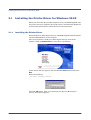
2.1.1
Installing the Printer Driver
Insert the Kyocera Mita Digital Library CD-ROM supplied with the printer
into the CD-ROM drive of the computer.
After a few moments, the Kyocera Mita Digital Library main menu
appears. Click on Install Drivers to start dirver installation.
If this screen does not appear, click the Windows Start button and select
Run.
Enter the following:
[CD drive letter]:\setup
Click the OK button. After a few moments, the Kyocera Mita Digital
Library main menu appears.
2-2
Printing From Applications
2.2
Printing From Applications
This section uses a document created using Microsoft Word as an example
of how to print from applications.
Note
When feeding from the paper cassette, do not insert paper into the MP
tray. Because the MP tray default setting is set to first mode (priority
printing from the MP tray), if there is paper inserted in the MP tray, the
first paper will always feed from there. To change the MP tray's first mode
setting, send the PRESCRIBE FRPO T0 command to the printer from the
Remote Operation Panel utility. (See section 1.6.7.) For FRPO commands,
refer to the Programming Manual provided on the CD-ROM supplied with
the printer.
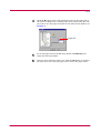
1
Set paper of the size specified for the document in the application
into the printer's paper cassette. (For details on how to set paper
sizes, refer to the Installation Manual.)
2
Set the paper size inserted into the paper cassette in the Remote
Operation Panel utility (see page 1-18). If paper size settings are not
the same, print may be incorrectly positioned.
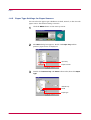
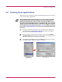
3
Create the print document, then click File from the menu bar. Next,
click Print, and the Print dialog box will appear.
Application
drop-down menu
2-3
Print dialog box
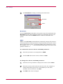
Printing From Applications
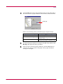
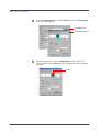
4
Click the Properties button in the Print dialog box. The Properties
dialog box is displayed.
Properties button
Properties dialog box
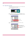
5
Click the paper size icon in the Paper Size list box so that it is
greyed, then click the OK button. A5 was selected for the following
example.
A5 size
2-4
Printing From Applications
6
Note
2.2.1
Once you finish making paper size settings, the Print dialog box is
displayed again. Click the OK button to start printing.
Settings made from applications are not saved when the application is
closed, and default settings are restored when the application is opened
the next time. To change the printer driver default settings, make printer
settings from Windows.
Feeding from the MP tray
First mode (priority printing) is set in the MP tray default settings.
To change the MP tray's first mode setting, send the PRESCRIBE FRPO
T0 command (!R! FRPO T0, 0; EXIT;) to the printer from the Remote
Operation Panel utility (see section 1.6.7). For FRPO commands, refer to
the Programming Manual provided on the CD-ROM supplied with the
printer.
2-5
Printing From Applications
2.2.2
Custom Size Settings
This printer can feed non-standard paper sizes. The paper cassette can
accommodate sizes ranging from 148 to 216 mm in width and 216 to 297
mm in length, and the MP tray can accommodate sizes ranging from 80 to
216 mm in width and 148 to 297 mm in length. The procedure for setting
custom sizes from the printer driver is explained below.
1
Display the printer driver's Properties dialog box from the
application software, then click Custom from the Paper Size list box
so that it becomes greyed.
Custom size
Paper Size list box
2
Click the Custom Size button to display the Custom Paper Size
dialog box.
Custom Size button
Custom Paper Size dialog box
2-6
Printing From Applications
3
Enter a name for your custom size and click the Add button.
Name settings
Add button
Units
Paper size
4
Select the unit or measurement, Inches and Millimeters.
5
Enter the height and width of the custom size in Size.
6
Click the OK button. The Print dialog box is displayed again. Click
the OK button to start printing.
2-7
Chapter 3
Maintenance
3
This chapter explains how to replace the toner container and how to clean parts such as the
registration roller and charger wire.
This chapter explains the following topics:
•
•
Toner Container Replacement
Cleaning
3-1
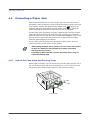
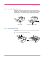
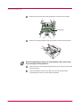
Toner Container Replacement
3.1
Toner Container Replacement
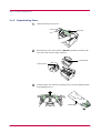
When the printer runs low on toner, the
(toner) indicator flashes on the
operator panel. Be sure to promptly replace the toner container and clean
the inside of the printer when this message appears.
If the printer stops printing while the
toner container to continue printing.
3.1.1
(toner) indicator is lit, replace the
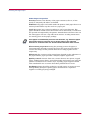
Toner Container Replacement Interval
Assuming an average toner coverage of 5%, with Ecoprint mode turned off
the toner container will need replacing approximately once every 6,000*
printed copies.
* In the case of a new printer in which a toner kit has been installed for
the first time, the number of copies that can be printed will be
approximately 3,000.
Toner Kit to be Used
Name:
TK-17
Description: Toner container
Wiper cloth
Plastic bag
User's manual
(The kit supplied with the printer only contains the toner
container and wiper cloth.)
Note
•
Be sure to distance items such as floppy disks during toner container
replacement.
•
Be sure to clean the inside of the printer when replacing the toner
container. For details, see 3.2 Cleaning.
•
Use of original Kyocera Mita toner kits is highly recommended to
prevent printer trouble and ensure the long life of the printer.
3-2
Toner Container Replacement
3.1.2
Replenishing Toner
1
Open the printer's top cover.
Top Cover
2
Pull lock lever #1 to the release (UNLOCK) position, then pull lock
lever #2 to the release (right) position.
Lock Lever #2
Lock Lever #1
3
Gently remove the old toner container. Put it in the supplied plastic
bag and dispose of it.
Plastic Bag
3-3
Toner Container Replacement
4
Take the toner container from the bag. Hold it with the protective
seal (orange-colored) facing up. Shake the toner container
horizontally at least 5 times. This ensures that the toner is evenly
distributed inside.
New Toner Container
5
Carefully remove the protective seal (orange-colored).
Protective Seal
6
Install the new toner container in the printer. Push firmly on the top
of the container at the positions marked PUSH HERE until you hear
it click in place.
3-4
Toner Container Replacement
7
While pushing down on the toner container, push lock lever #1 to the
lock (LOCK) position. (Lock lever #2 is automatically locked.)
UNLOCK
LOCK
UNLOCK
LOCK
Lock Lever #1
Note
If the toner low indication flashes or remains lit after installing the new
toner container, take the toner container out once, shake it well, then
install again.
3-5
Cleaning
3.2
Cleaning
To avoid print quality problems, the interior of the printer must be cleaned
with every toner container replacement.
Cleaning should be done from time to time to avoid print quality
problems.
Note
3.2.1
Printer Interior
To avoid print quality problems due to paper dust and debris, clean the
interior of the printer in the following manner.
1
Open the printer's top and front covers.
Top Cover
Front Cover
2
Lift the process unit together with the toner container out of the
printer. The drum in the process unit is sensitive to light.
Never expose the drum even to normal office lighting (500
lux) for more than five minutes.
Process Unit
3-6
Cleaning
Never stand the process unit on end.
NO
Note
3
Use the supplied wiper cloth to clean dust and dirt away from the
registration roller (metal).
Transfer Roller
Registration Roller
While cleaning, be careful to avoid touching the transfer roller (the black
roller).
Note
4
Slide the charger cleaner knob (green-colored) back and forth 2 to 3
times, then return it to its CLEANER HOME POSITION
.
Charger Cleaner Knob
After cleaning, make sure you restore the charger cleaner to its home
position.
3-7
Cleaning
Note
If the charger cleaner knob is not restored to its home position (marked
CLEANER HOME POSITION
), a black band will print along the length
of the page the next time you use the printer.
5
After cleaning is done, put the process unit back in the printer. To do
so, carefully align the guides at both ends of the process unit with
the slots in the printer.
Process Unit
6
Close the front cover.
Front Cover
7
Close the top cover by pressing down on the front left and right
corners of the top cover.
Top Cover
3-8
Chapter 4
Troubleshooting
4
This chapter explains how to handle printer problems that may occur. If a problem cannot be
corrected, contact your Kyocera Mita dealer.
This chapter explains the following topics:
•
•
•
•
General Guide
Print Quality Problems
Indicators
Correcting a Paper Jam
4-1
General Guide
4.1
General Guide
There are quite a few printer problems which may be corrected by the user.
This section explains how to correct these problems.
If some kind of printer problem should occur, check the following before
concluding the printer is broken.
Symptom
The printer will not
print from the
computer.
Check Items
Check the
indicator.
Check if status page can
be printed.
Corrective Action
Off
Look through the items below and check
anything that seems appropriate.
Flashing
Rapid flashing: An error has occurred. For
details on error warnings and remedies, see
section 4.3 Indicators.
Flickering: The printer is offline. Pressing the
key switches the printer to online status.
Lit
See the appropriate item below.
Status page
can be
printed.
There may be a problem with the computer's
connection to the network. Also, look through
the items below and check anything that
seems relevant.
Print quality is not good.
See section 4.2 Print Quality Problems.
Paper is jammed.
See section 4.4 Correcting a Paper Jam.
Nothing lights on the
operator panel even
when power is turned
on and the fan makes
no noise.
Check that the power cord is properly
plugged into the power outlet.
The printer prints a
status page, but data
from the computer is
not being printed
normally.
Check the interface cable.
Connect both ends of the interface cable
securely. Try replacing the printer cable. For
details on the parallel interface for this
printer, see Appendix C.
Check program files and application
software.
Try printing another file or using another
print command. If the problem occurs only
with a specific file or application, check the
printer settings for that application.
Turn off the printer's power, plug in the power
cord securely, and try turning on the printer's
power again.
Check that the power switch is really in the ON ( ❘ ) position.
If you still cannot correct a printer problem even after checking the above,
please contact your Kyocera Mita dealer.
4-2
Print Quality Problems
4.2
Print Quality Problems
As the following table shows, there are many possible causes of print
quality problems, such as blank output as. The troubleshooting procedure
for each type of problem is explained below. If you still can not solve the
problem, contact your Kyocera Mita dealer.
Printed Results
Corrective Action
All-black printout
Contact your Kyocera Mita dealer.
Dropouts, horizontal streaks, stray dots
Clean the charger wire.
Open the printer's top and front covers. Remove the
process unit from the printer and slide the charger knob
back and forth to clean the charger wire.
(See Chapter 3)
Black or white vertical streaks
Check the operator panel.
When the
(toner) indicator is flashes, install a new
toner kit. Clean the printer after replacement.
(See Chapter 3)
Clean the charger wire.
Open the printer's top and front covers. Remove the
process unit from the printer and slide the charger knob
back and forth to clean the charger wire.
(See Chapter 3)
Check the position of the charger cleaner knob
Open the printer's top and front covers. Remove the
process unit from the printer. Make sure the charger
cleaner knob is restored to its home position.
(See Chapter 3)
(Continued on next page)
4-3
Print Quality Problems
Printed Results
Corrective Action
Faint or blurred printing
Check the Ecoprint setting. (See Chapter 1)
When this setting is On, switch it to Off on the Remote
Operation Panel. (See Chapter 1)
Confirm the
(toner) indicator.
If the
(toner) indicator flashes, install a new toner
kit. (See Chapter 3)
Clean the charger wire.
Open the printer's top and front covers. Remove the
process unit from the printer and slide the charger knob
back and forth to clean the charger wire.
(See Chapter 3)
Try setting the thin paper mode.
Set the paper type to Thin in the Remote Operation
Panel utility. (See Chapter 1)
Grey background.
Check the operator panel.
When the
(toner) indicator is flashes, install a new
toner kit. (See Chapter 3)
Check the process unit.
Open the printer's top cover and front cover, then check
that the process unit is properly installed.
Dirt on the top edge or back of the paper
Check the transfer roller.
Open the printer's top and front covers. Remove the
process unit from the printer and check whether the
transfer roller is dirty. If so, print several pages to
eliminate the dirt.
Check the registration roller.
Open the printer's top and front covers. Remove the
process unit from the printer and check whether the
registration roller is soiled with toner. If so, wipe it clean
using the supplied wiper cloth.
Characters out of position.
Check the file or program.
Check whether the problem is being caused by a
PRESCRIBE command error. If the problem occurs only
with a specific file or program, the most likely cause is an
error in a parameter to a command or command syntax.
Check the paper size setting.
Check that the paper size set in the paper source and the
paper size set on the Remote Operation Panel are the
same. (See section 1.4.4 )
4-4
Indicators
4.3
Indicators
There are four indicators on the printer's operator panel. These light, flash,
and turn off in combination to indicate the printer's current status. This
section explains the indicators on the operator panel and the appropriate
corrective action to take in each case.
Indicator displays can be classified into three categories: maintenance,
errors, and normal. In the following table, indicators are shown to be lit,
flashing, or off. Further, flashing is divided into two speeds, fast and slow.
Lit
Red/Green
Fast Flashing
Red/Green
Slow flashing
Red/Green
Off
Grey
By using the Remote Operation Panel utility, you can monitor the printer's
status from the computer. When a printer error occurs, the error message
is displayed on the computer's screen. The Remote Operation Panel's
display is described in the following tables.
4-5
Indicators
4.3.1
Maintenance Messages
The following table lists error messages that can be dealt with by the user.
Read the explanations carefully.
Indicator
Remote Operation
Panel display
Add paper <paper source>
<size>
Corrective Action
The paper has run out. Add paper to the
paper cassette or MP tray.
The paper source and paper size are displayed in
the Remote Operation Panel.
Press the
key to switch, the paper source
between the MP tray, the paper cassette, and the
paper feeder (optional) in that order.
The paper cassette is not closed securely.
Close the paper cassette properly.
The cassette paper size and data paper size
are not the same.
The printer feeds from the MP Tray when the page
in the paper cassette is a different size than that
specified in the print data. Set paper of the size
specified in the print data into the MP tray, then
Load MP tray
<paper size>
press the
key to resume printing.
When you want to feed from a source other than the
MP tray, make sure there is no paper in the MP
tray, then press the
key to switch the paper
source. The printer prints on the paper size set in
that particular paper source.
Paper jam
Open the printer and clear the paper jam.
For details on how to clear paper jams, see section
4.4 .
Replace Toner
TK-17
There is no more toner in the toner container.
The printer has stopped because there is no more
toner. Replace with a new toner kit. After replacing,
be sure to clean the printer. (See Chapter 4)
(Continued on next page)
4-6
Indicators
Indicator
Remote Operation
Panel display
Corrective Action
Toner low
TK-17
There is not enough toner inside the toner
container.
Promptly replace with a new toner as the printer
will stop printing before long. Clean the printer
after replacement. (See Chapter 4)
Top cover
Open
The top or front cover is open.
Close the cover properly.
Warning Waste
toner bottle
The waste toner reservoir is almost full.
The waste toner reservoir will become full and the
printer will stop printing.
4-7
Indicators
4.3.2
Errors Requiring Service Personnel Attention
When the following errors occur, turn off your printer, remove the plug
from the AC outlet, and contact your Kyocera Mita dealer. The indicators
are shown in two different states, according to the way they alternate.
Indicator
Remote Operation
Panel display
Corrective Action
Call service
personD9:0123456
The waste toner reservoir is full (D9 error)
Turn off the printer's power and remove the process
unit from the printer. Gently shake the process unit
horizontally a few times, then reinstall it into the
printer. Turn on the printer's power. If this error
message does not disappear, contact your Kyocera
Mita dealer (less than 100,000 pages printing).
Call service
personDA:0123456
The waste toner reservoir is full (DA error)
Same as above (100,000 pages printing or more).
Call service
personE1:0123456
Main motor error (E1 error)
Contact your Kyocera Mita dealer.
Call service
personE2:0123456
Scanner motor error (E2 error)
Contact your Kyocera Mita dealer.
0123456: Total number of pages printed.
(Continued on next page)
4-8
Indicators
Indicator
Remote Operation
Panel display
Corrective Action
Call service
personE3:0123456
Scanner pin-photo error (E3 error)
Contact your Kyocera Mita dealer.
Call service
personE4:0123456
Fuser error (E4 error)
Contact your Kyocera Mita dealer.
Call service
personE5:0123456
Eraser error (E5 error)
Contact your Kyocera Mita dealer.
Call service
personF1:0123456
Controller check sum error (F1 error)
Contact your Kyocera Mita dealer.
0123456: Total number of pages printed.
(Continued on next page)
4-9
Indicators
Indicator
Remote Operation
Panel display
Corrective Action
Call service
personF2:0123456
Controller RAM read/write error (F2 error)
Contact your Kyocera Mita dealer.
Call service
personF3:0123456
Controller system error (F3 error)
Contact your Kyocera Mita dealer.
0123456: Total number of pages printed.
4-10
Indicators
4.3.3
Error Messages
With the following errors, printing continues when you press the printer's
key. You can confirm these errors by printing a status page. (See pages
1-4 and 1-5.)
Indicator
Remote Operation
Panel display
Corrective Action
KPDL Error
Press GO
Current print processing cannot continue.
(Only occurs if the optional KPDL2 Upgrade kit
[PK-6] is installed on your printer.)
Press the
key to resume printing. You can
abandon printing by pressing the
key.
Memory overflow
Press GO
Printing cannot continue because there is
not enough memory.
Try adding more memory. Press the
key to
resume printing. You can abandon printing by
pressing the
key.
Print overrun
Press GO
Current print processing cannot continue
due to complex data.
The data transferred to the printer was too complex
to print on a page. Press the
key to print data as
far as it was stored. You can abandon printing by
the
key.
Note
To release the page protect mode, send the
following command to the printer from the
Remote Operation Panel after this error
occurs:
!R! FRPO R5, 1; EXIT;
Check the error code displayed in ## and
refer to the appropriate description below.
01: Abnormal format. Try turning the power off
and on again.
02: RAM disk mode is Off. Turn RAM disk mode
On.
03: Cannot write to the disk system because it is
write protected. Remove the write protection.
04: No disk space. Clean up files.
05: Specified file not on disk.
06: No memory for use by disk system. Expand
printer memory.
10: Cannot format disk because host data is
spooled there. Format the disk after Ready is
displayed.
98: Unable to read files during sorting (file does
not exist, or is corrupted).
RAM DISK err ##
Press GO
4-11
Indicators
4.3.4
Normal Indicator Display
The following displays appear during normal printer operation.
Indicator
Remote Operation
Panel display
Description
Cancelling data
Data inside the printer is being canceled.
The indicators light in sequence from the top, then
go off in sequence from the bottom. This process is
repeated twice.
Please wait
The printer is warming up and is not ready to print.
The indicators light in sequence twice from top to
bottom.
Processing
The printer is receiving data.
The printer is processing data, or the printer is
waiting for a code or command signalling that the
job is finished.
The printer is ready to print.
Ready
The printer is offline. The printer stores but does
not print received data.
The printer is in sleep mode. The
indicator
flashes at 5-second intervals and all other
indicators go off. The printer wakes from Sleep
mode whenever a key on the operator panel is
pressed, the cover is opened or closed, or data is
received. The printer then warms up and goes
online. (You can set the amount of time before the
printer enters sleep mode from the Remote
Operation Panel utility.)
Sleeping
4-12
Correcting a Paper Jam
4.4
Correcting a Paper Jam
This section describes how to remove paper when it jams in the printer.
The printer will stop whenever paper jams in the printer or paper is not fed
from a paper cassette. The printer will go offline and
(paper jam)
indicator will light in the operator panel. When a jam occurs, check the
points indicated in the following and clear the jam as indicated.
If paper jams occur frequently, try using a different type of paper, replace
with paper from another ream, turn the stack of paper over, or turn the
paper the other way around. Read the information in Chapter 5. Also, look
for tiny pieces of paper that may have been torn apart and overlooked
when the jammed paper was removed.
If you cannot solve the problem by changing the paper, there may be a
problem with the printer. Call a service person.
•
When pulling the paper, pull it gently so as not to tear it. Torn pieces
of paper are difficult to remove and may be easily overlooked,
deterring the jam recovery.
•
Depending on where the jam occurred, the printer may or may not
reprint the jammed page.
Note
4.4.1
Jam at the Face-down and Face-up Trays
When paper is fed part way out into the tray, pull the paper out the rest of
the way by hand. Open and close the printer's top cover to clear the error.
The printer then automatically warms up and resumes printing.
Face-up Tray
4-13
Correcting a Paper Jam
4.4.2
Jam at the Paper Cassette
Pull out the paper cassette and remove any partially fed paper, then reclose the paper cassette. Open and close the printer's top cover to clear the
error. The printer then automatically warms up and resumes printing.
Follow the same steps for clearing the jammed paper at the option paper
feeder's paper cassette.
Paper Feeder
(Option)
Paper Cassette
4.4.3
Paper Feeder's Paper Cassette
Jam Inside the Printer
When a paper jam occurs inside the printer, clear it using the following
procedure.
1
Open the printer's top and front covers.
Top Cover
Front Cover
4-14
Correcting a Paper Jam
2
Remove the process unit from the printer as shown in the figure.
Process Unit
3
Remove the jammed paper from the printer as shown in the figure.
When the jammed paper appears to be pinched by rollers, pull it along
the normal paper running direction.
Note
4
After you have removed the jammed paper, put the process unit back
into the printer.
5
Close the printer's front cover and top cover. The printer then
automatically warms up and resumes printing.
4-15
Chapter 5
Paper Selection
5
This chapter explains the following topics:
•
•
•
General Guidelines
Selecting the Right Paper
Special Paper
5-1
General Guidelines
5.1
General Guidelines
The printer is designed to print on high-quality copier bond paper (the kind
used in ordinary dry copier machines), but it can also accept a variety of
other types of paper within the limits specified below.
The manufacturer assumes no liability for problems that occur when
paper not satisfying these requirements is used.
Note
5.1.1
Selection of the right paper is important. Using the wrong paper can result
in paper jams, misfeeding, curling, poor print quality, and paper waste, and
in extreme cases can damage the printer. The guidelines given below will
increase the productivity of your office by ensuring efficient, trouble-free
printing and reducing wear and tear on the printer.
Paper Availability
Most types of paper are compatible with a variety of machines. Paper
intended for xerographic copiers can also be used with the printer.
There are three general grades of paper: economy, standard, and premium.
The most significant difference between grades is the ease with which they
pass through the printer. This is affected by the smoothness, size, and
moisture content of the paper, and the way in which the paper is cut. The
higher the grade of paper you use, the less risk there will be of paper jams
and other problems, and the higher the level of quality your printed output
will reflect.
Differences between paper from different suppliers can also affect the
printer's performance. A high-quality printer cannot produce high-quality
results when the wrong paper is used. Low-priced paper is not economical
in the long run if it causes printing problems.
Paper in each grade is available in a range of basis weights (defined later).
The traditional standard weights are 16, 20, and 28 pounds (60 to 105 g/m2).
5.1.2
Paper Specifications
The following table summarizes the basic paper specifications. Details are
given on the following pages.
Table 5.1 Specifications
Item
Specification
Weight
Cassette : 60 to 105 g/m2 (16 to 28 lb/ream)
MP tray : 60 to 163 g/m2 (16 to 43 lb/ream)
Thickness
0.086 to 0.110 mm (3.4 to 4.3 mils)
Dimensional accuracy
±0.7 mm (±0.0276 inches)
Squareness of corners
90° ±0.2°
Moisture content
4% to 6%
Direction of grain
Long grain
Pulp content
80% or more
5-2
Selecting the Right Paper
5.2
Selecting the Right Paper
Laser printing is a process involving laser light, electrostatic discharge,
toner, and heat. In addition, as the paper passes through the printer it
undergoes considerable sliding, bending, and twisting motions. A highquality printing paper matching the printer's requirements withstands all
these stresses, enabling the printer to turn out clean, crisp printed copies
consistently.
Remember that all paper is not the same. Some of the factors to consider
when selecting paper for the printer are as follows:
Condition of the Paper
Avoid using paper that is bent at the edges, curled, dirty, torn, embossed, or
contaminated with lint, clay, or paper shreds.
Use of paper in these conditions can lead to illegible printing, misfeeding,
and paper jams, and can shorten the life of the printer. In particular, avoid
using paper with a surface coating or other surface treatment. The paper
should have as smooth and even a surface as possible.
Composition
Do not use paper that has been coated or surface-treated and contains
plastic or carbon. The heat of fusing can cause such paper to give off
harmful fumes.
Bond paper should contain at least 80% pulp. Not more than 20% of the
total paper content should consist of cotton or other fibers.
5-3
Selecting the Right Paper
Paper Size
Cassettes and an MP tray are available for the paper sizes listed in
Table 5.2. The dimensional tolerances are ±0.7 mm (±0.0276 inches) for
the length and width. The angle at the corners must be 90° ±0.2°.
Table 5.2 Paper Sizes for Paper Feeding
Multi-Purpose tray
Size
Cassette or multipurpose tray
Size
Monarch
3-7/8 × 7-1/2 inches
Legal (Not available with
the MP tray)
8-1/2 × 14 inches
Business
4-1/8 × 9-1/2 inches
Letter
8-1/2 × 11 inches
International DL
11 × 22 cm
ISO A4
210 × 297 mm
International C5
16.2 × 22.9 cm
ISO A5
148 × 210 mm
International B5
17.6 × 25 cm
JIS B5
182 × 257 mm
Executive
7-1/4 × 10-1/2 inches
Custom
148 to 216 mm × 210 to 297
mm (5-13/16 to 8-1/2
inches × 8-1/4 to 14 inches)
Commercial 9
3-7/8 × 8-7/8 inches
Commercial 6-3/4
3-5/8 × 6-1/2 inches
ISO A6
105 × 148 mm
Other sizes of paper can be fed manually. The minimum
size paper for manual feed is 80 × 148 mm (3-1/8 × 5-13/
16 inches), fed lengthwise. The maximum size is 216 ×
356 mm (8-1/2 × 14 inches).
JIS B6
128 × 182 mm
Hagaki
100 × 148 mm
Ofuku-Hagaki
148 × 200 mm
Smoothness
The paper should have a smooth, uncoated surface. Paper with a rough or
sandy surface can cause voids in the printed output. Paper that is too
smooth, however, can cause multiple feeding and fogging problems.
(Fogging is a gray background effect.)
Basis Weight
Basis weight is the weight of a standard quantity of paper. In the
traditional system the standard quantity is a ream consisting of 500 sheets
measuring 17 × 22 inches each. In the metric system the standard quantity
is 1 square meter.
Paper that is too light or too heavy can cause misfeeding, jams, and
premature wear of the printer. Uneven paper weight can cause multiple
feeds, print defects, poor toner fusing, blurring, and other print quality
problems. The proper weight is 60 to 105 g/m2 for the paper cassette, and
60 to 163 g/m2 for the MP tray.
5-4
Selecting the Right Paper
Thickness (Caliper)
Thick paper is referred to as high-caliper paper and thin paper as lowcaliper paper. The paper used with the printer should be neither extremely
thick nor extremely thin. If you are having problems with paper jams,
multiple feeds, and faint printing, the paper you are using may be too thin.
If you are having problems with paper jams and blurred printing the paper
may be too thick. The proper thickness is 0.086 to 0.110 mm (3.4 to 4.3
mils).
Moisture Content
Moisture content is defined as the percent ratio of moisture to the dry mass
of the paper. Moisture can affect the paper's appearance, feedability, curl,
electrostatic properties, and toner fusing characteristics.
The moisture content of the paper varies with the relative humidity in the
room. When the relative humidity is high and the paper absorbs moisture,
the paper edges expand, becoming wavy in appearance. When the relative
humidity is low and the paper loses moisture, the edges shrink and
tighten, and print contrast may suffer.
Wavy or tight edges can cause misfeeding and alignment anomalies. The
moisture content of the paper should be 4 to 6%.
To ensure the proper moisture content it is important to store the paper in
a controlled environment. Some tips on moisture control are:
•
Store paper in a cool, dry location.
•
Keep the paper in its wrapping as long as possible. Rewrap paper that
is not in use.
•
Store paper in its original carton. Place a pallet etc. under the carton to
separate it from the floor.
•
After removing paper from storage, let it stand in the same room as the
printer for 48 hours before use.
•
Avoid leaving paper where it is exposed to heat, sunlight, or damp.
Paper Grain
When paper is manufactured, it is cut into sheets with the grain running
parallel to the length (long grain) or parallel to the width (short grain).
Short grain paper can cause feeding problems in the printer. All paper used
in the printer should be long grain.
5-5
Selecting the Right Paper
Other Paper Properties
Porosity: Refers to the density of the paper structure; that is, to how
openly or compactly the fibers are bonded.
Stiffness: Limp paper can buckle inside the printer, while paper that is too
stiff may bind. Either way the result is a paper jam.
Curl: Most paper has a natural tendency to curl in one direction. The
paper should be loaded so that the natural curl is downward, to counteract
the upward curl imparted by the printer. Printed sheets will then come out
flat. Most paper also has a top and bottom surface. Loading instructions
are usually given on the paper package.
Note
If the paper is considerably curled in one direction, e.g. when the paper
was used to print on one side, try to roll the paper in the opposite
direction to counteract the curl. Printed sheets will then come out flat.
Electrostatic properties: During the printing process the paper is
electrostatically charged to attract the toner. The paper must be able to
release this charge so that printed sheets do not cling together in the
output tray.
Whiteness: The contrast of the printed page depends on the whiteness of
the paper. Whiter paper provides a sharper, brighter appearance.
Quality control: Uneven sheet size, corners that are not square, ragged
edges, welded (uncut) sheets, and crushed edges and corners can cause the
printer to malfunction in various ways. A quality paper supplier should
take considerable care to ensure that these problems do not occur.
Packaging: Paper should be packed in a sturdy carton to protect it from
damage during transport. Quality paper obtained from a reputable
supplier is usually properly packaged.
5-6
Special Paper
5.3
Special Paper
The following types of special paper can be used:
•
Transparency (overhead projection film)
•
Adhesive-backed label paper
•
Envelopes
•
Colored paper
•
Preprinted paper
•
Recycled paper
Use paper that is sold specifically for use with copiers (heat-fusing type).
transparency, label paper, and envelopes should not be placed in the paper
cassette; they must be fed from the MP tray and delivered in the face up
stack.
Since the composition and quality of special paper vary considerably,
special paper is more likely than white bond paper to give trouble during
printing. No liability will be assumed if moisture and so forth given off
during printing on special paper causes harm to the machine or operator.
Before purchasing any type of special paper, test a sample on the printer
and check that printing quality is satisfactory.
Note
Specifications for each type of special paper are given below.
5.3.1
Transparency (overhead projection film)
Transparency must be able to withstand the heat of fusing during the
printing process. It should satisfy the conditions in Table 5.3.
Table 5.3 Transparency Specifications
Item
Specification
Tolerance of heat
Must tolerate at least 190°C (374°F)
Thickness
0.100 to 0.110 mm (3.9 to 4.3 mils)
Material
Polyester
Dimensional accuracy
±0.7 mm (±0.0276 in)
Squareness of corners
90° ± 0.2°
To avoid trouble, transparency must be delivered face-up.
If transparency jams frequently, pull the top of the sheet very gently as it
leaves the printer.
5-7
Special Paper
5.3.2
Adhesive-Backed Labels
The basic rule for printing on adhesive labels is that the adhesive must
never come into contact with any part of the printer. Adhesive paper
sticking to the drum or rollers will damage the printer.
Label paper must be manually fed.
Label paper has a structure comprising three layers, as shown in
Table 5.1. The top sheet is printed on. The adhesive layer consists of
pressure-sensitive adhesives. The carrier sheet (also called the linear or
backing sheet) holds the labels until use. Due to the complexity of its
composition, adhesive-backed label paper is particularly likely to give
trouble in printing.
Top sheet (white bond paper)
Adhesive
Carrier sheet
Figure 5.1 Adhesive-back label
Adhesive label paper must be entirely covered by its top sheet, with no
spaces between the individual labels. Labels with spaces in between are
apt to peel off, causing serious paper jam problems.
Some label paper is manufactured with an extra margin of top sheet
around the edge. Do not remove the extra top sheet from the carrier sheet
until after printing is finished.
Acceptable
Unacceptable
Top sheet
Carrier sheet
Figure 5.2 Label arrangement
5-8
Special Paper
Table 5.4 lists the specifications for adhesive label paper.
Table 5.4 Adhesive Label Specifications
Item
Specification
Weight of top sheet
44 to 74 g/m2 (12 to 20 lb/ream)
Composite weight
104 to 151 g/m2 (28 to 40 lb/ream)
Thickness of top sheet
0.086 to 0.107 mm (3.9 to 4.2 mils)
Composite thickness
0.115 to 0.145 mm (4.5 to 5.7 mils)
Moisture content
4 to 6% (composite)
Envelopes
The printer can print on envelopes using paper with a basis weight of 60 to
79 g/m2 (16 to 21 lb/ream). Envelopes must be manually fed.
An envelope is a more complex object than a single sheet of paper. For this
reason, it may not be possible to obtain consistent printing quality over the
entire envelope surface.
Many envelopes have a diagonal grain orientation. (See Paper Grain
above.) This orientation is more likely to wrinkle and crease on its way
through the printer. Before purchasing envelopes for use with the printer,
test a sample to verify the envelope's suitability.
Do not use envelopes that have an encapsulated liquid adhesive.
Avoid long printing runs consisting of envelopes only. Extensive envelope
printing can cause premature printer wear.
To avoid jamming due to curled envelopes, do not leave more than
approximately 10 printed envelopes stacked in the paper trays during
multiple envelope printing.
Colored Paper
Colored paper should satisfy the same conditions as white bond paper,
listed in Table 5.1 on page 5-2. In addition, the pigments used in the paper
must be able to withstand the heat of fusing during the printing process
(up to 200°C or 392°F).
Preprinted Paper
Preprinted paper should have a bond paper base. The preprinted ink must
be able to withstand the heat of fusing during the printing process, and
must not be affected by silicone oil.
Do not use paper with any kind of surface treatment, such as the type of
paper commonly used for calendars.
5-9
Special Paper
Recycled Paper
Select recycled paper that meets the same specifications as the white bond
paper (see Table 5.1 on page 5-2) except whiteness.
Before purchasing recycled paper, test a sample on the printer and check
that the printing quality is satisfactory.
Note
5-10
Appendix A
Fonts
A
This chapter describes the types of fonts you can use with the printer, including the printer's
internal fonts.
This appendix explains the following topics:
•
•
Internal Fonts
List of Fonts
A-1
Internal Fonts
A.1
Internal Fonts
A font is a set of characters of a particular design. The design is referred to
as a typeface. Several characteristics identify a font. These include the code
set (for details on code sets, please read the Programming Manual
provided on the CD-ROM supplied with the printer), spacing, pitch, height,
style, stroke weight, and typeface family.
The printer comes with 45 preinstalled PCL compatible fonts and a line
printer bitmap font. Fonts may also be downloaded to the printer's memory.
These are referred to as downloadable or soft fonts. The printer accepts as
many downloadable fonts as its user available memory permits.
A-2
List of Fonts
A.2
List of Fonts
This section contains a full list of the printer's internal fonts. Fonts marked
with an asterisk can only be used if the optional KPDL2 Upgrade Kit (PK-6)
is installed on your printer.
A.2.1 Internal Scalable and Bitmap Fonts
Font
number
Font samples
0
1
2
3
4
5
6
7
8
9
10
11
12
13
14
15
16
17
18
19
20
21
22
23
24
25
26
27
28
29
30
A-3
List of Fonts
Font
number
Font samples
31
32
33
34
35
36
37
*
38
*
39
*
40
*
41
*
42
*
43
*
44
*
45
*
46
*
47
*
48
*
49
*
50
*
51
*
52
*
53
*
54
*
55
*
56
*
57
*
58
*
59
*
60
*
61
*
62
*
63
*
64
*
65
*
66
67
*
68
69
*
A-4
List of Fonts
Font
number
Font samples
70
71
72
73
74
75
76
*
77
*
78
*
79
*
80
A-5
Appendix B
Expansion Memory
Installation
B
This appendix explains how to expand the printer's memory. Expanded printer memory
enables you to print more complex pages, download more fonts, and define more macros.
B-1
This appendix begins by explaining how to install a DIMM (dual in-line
memory module) on the main circuit board.
The FS-1000+ comes supplied with 4 MB of memory installed. A slot is
provided for expanding the memory in your printer so that more complex
printing can be done, as well as increasing the printing speed. By installing
optional DIMM into your printer, the memory in the FS-1000+ can be
increased to a maximum of 132 MB.
•
The expansion memory should be installed only by a Kyocera Mita
authorized dealer or Kyocera Mita certified technician. Kyocera Mita
shall not be liable for damage due to improper installation of the
expansion memory.
•
The following instructions are intended for the technician only.
Note
Notes on Handling the Main Circuit Board and DIMM
Protect the electronics by taking these precautions:
•
Before touching a DIMM, touch a water pipe or other large metal object
to discharge yourself of static electricity. While doing the work, it is
recommended that you wear an antistatic wrist strap.
•
Touch the main circuit board and DIMM only by the edges.
YES
NO
B-2
DIMM to be used
See your Kyocera Mita dealer for purchasing information of the DIMM that
are best suited for use with this printer.
Either an 8 MB, 16 MB, 32 MB, 64 MB, or 128 MB DIMM can be used for
memory expansion.
Installing the DIMM
Insert the DIMM into the socket as follows:
1
Turn the printer's power off, then unplug the printer's power cable
and disconnect the printer from the host computer.
2
Remove the screw from the rear of the printer.
3
Remove the side cover as shown in the figure.
Side Cover
B-3
After removing the side cover, you can see the DIMM socket on top of
the main circuit board.
DIMM socket
4
5
Remove the DIMM from its package.
Open the clips on both ends of the DIMM socket.
Clips
6
Insert the DIMM into the DIMM socket so that the notches on the
DIMM align with the corresponding protrusions in the slot.
DIMM
B-4
7
Close the clips on the DIMM slot to secure the DIMM.
8
When you have finished installing the DIMM, replace the side cover
and fasten it with the screw.
To remove a DIMM:
Remove the side cover as shown in steps 1 to 3 on page B-3, then carefully
pull the end clips outwards and pull the DIMM out of the socket.
Testing the Expansion Memory
After you have finished installing DIMM in the printer, test the printer to
see if installation succeeded.
To test the expansion memory, proceed as follows:
1
Make sure the power switch is off. Plug the power cord into the
printer and turn on the power.
2
When the printer is online, press and hold the
more.
3
If the installation succeeded, the amount of memory shown on the
status page will correspond with the amount of expansion memory.
(The factory installed memory size is 4 MB.)
B-5
key 3 seconds or
Appendix C
Host Computer
Interface
C
This appendix describes the signals used in the laser printer's parallel and RS-232C/RS422A interfaces. It also lists pin assignments, signal functions, timings, connector
specifications, and voltage levels. The RS-232C/RS-422A protocols are also covered. Finally,
it explains how to use the printer in a multi-computer environment.
This appendix explains the following topics:
•
•
•
•
Parallel Interface
Serial Interface (Option)
RS-232C/RS-422A Protocol
RS-232C Cable Connection
C-1
Parallel Interface
C.1
Parallel Interface
C.1.1
Parallel Interface Communication Modes
The printer features fast data transmission on the parallel interface. The
parallel interface mode can be activated from the Remote Operation Panel
utility contained on the Kyocera Mita Digital Library CD-ROM supplied
with the printer as follows:
Use a parallel printer cable that complies with the IEEE1284 standard.
Note
Auto [default]
The printer automatically changes its communication mode to the one the
host computer is currently using. Ordinarily, you should leave this setting
unchanged.
Nibble (high)
High speed data communication is used in compliance with the IEEE 1284
standard.
Normal
The printer uses the standard communication method prescribed for
Centronics interfaces.
High-speed
This mode enables faster data transmission between the printer and the
host computer.
(Select this mode if printing problems occur when the printer is connected
to a workstation.)
C.1.2
Interface Signals
The pins of the parallel interface connector carry the signals listed in
Table C. 1. Asterisks in the table indicate signals that are active low. The
table also indicates whether each signal is incoming or outgoing with
respect to the printer.
-2
Parallel Interface
Table C. 1 Parallel Connector Pin Assignment
Pin
In/out
Description
1
In
Strobe* [nStrobe]
2
In
Data 0 [Data 1]
3
In
Data 1 [Data 2]
4
In
Data 2 [Data 3]
5
In
Data 3 [Data 4]
6
In
Data 4 [Data 5]
7
In
Data 5 [Data 6]
8
In
Data 6 [Data 7]
Data 7 [Data 8]
9
In
10
Out
Acknowledge* [nAck]
11
Out
Busy [Busy]
12
Out
Paper Empty [PError]
13
Out
14
In
15
-
Not connected
16
-
0V DC
17
-
Chassis GND
18
-
+5V DC
19
-
Ground return
20
-
Ground return
21
-
Ground return
22
-
Ground return
23
-
Ground return
24
-
Ground return
25
-
Ground return
26
-
Ground return
27
-
Ground return
28
-
Ground return
29
-
Ground return
30
-
Ground return
31
In
32
Out
33
-
-
34
-
Not connected
35
Out
Power Ready
36
In
Online (Select) [Select]
Ignored [nAutoFd]
Reset [nInit]
Error*, returns error status if FRPO O2=2 [nFault]
Select In [nSelectIn]
[ ]: Signal names in the Auto mode and Nibble (high) mode (IEEE 1284). In the Auto mode and
Nibble (high) mode, these signals are bi-directional.
C-3
Parallel Interface
Detailed descriptions of the signals follow.
Strobe* [nStrobe] (Pin 1)
A negative-going Strobe* pulse causes the printer to read and latch the
data on the Data 0 [1] to Data 7 [8] signal lines.
Data 0 [1] to Data 7 [8] (Pins 2 to 9)
These eight signals form the data byte sent from the host computer to the
printer. Data 7 [8] is the most significant bit.
Acknowledge* [nAck] (Pin 10)
This negative-going pulse acknowledges the previous character received by
the printer.
Busy [Busy] (Pin 11)
This signal is high when the printer is busy and low when it is able to
accept more data.
Paper Empty [PError] (Pin 12)
This signal goes high when the printer runs out of paper.
Online [Select] (Pin 13)
This signal is high when the printer is online and low when the printer is
offline. It goes low when the upper unit is raised, or when the
key is
pressed to set the printer offline.
The Paper Empty and Online signals are not used unless enabled by the
FRPO command (O2 parameter).
Note
+5V DC (pin 18)
This line is connected to the printer's +5V DC line (+5 V ±0.5 V, maximum
400 mA, fused.)
Reset [nInit] (Pin 31)
This signal is used in the standard Centronics interface to enable the
computer to reset the printer.
Error* [nFault] (Pin 32)
When the high-speed parallel line control is on (FRPO O2=2), this line
returns error status.
Auxiliary output 1 (Pin 33)
This signal line is not used.
C-4
Parallel Interface
Power Ready (Pin 35)
This signal is high when the printer's power is on.
Select In [nSelectIn] (Pin 36)
This signal is used in some versions of the Centronics interface to enable
the computer to force the printer online.
C-5
Serial Interface (Option)
C.2
Serial Interface (Option)
Installing the optional serial interface kit (IB-10E) in the printer enables
connection to a computer with an RS-232C or RS-422A standard serial
interface.
C.2.1
RS-232C Interface
Interface Signals
The pins of the printer's RS-232C interface connector carry the
signals listed in Table C. 2. The table also indicates whether each
signal is incoming or outgoing with respect to the printer.
Table C.2 RS-232C Signal Pin Assignments
Pin
In/out
Signal
Description
1
-
FG
2
Out
TXD
Transmit Data
3
In
RXD
Receive Data
4
Out
RTS
Request To Send
5
In
CTS
Clear To Send
6
In
DSR
Data Set Ready
7
-
SG
Signal Ground
20
Out
DTR
Frame ground
Data Terminal Ready
Brief descriptions of the signals follow.
FG - Frame Ground - (Pin 1)
This pin is connected directly to the printer frame.
TXD - Transmit Data - (Pin 2)
This output carries asynchronous data sent by the printer to the computer.
It is used mainly in handshaking protocols.
RXD - Receive Data - (Pin 3)
This input carries serial asynchronous data sent by the computer to the
printer.
RTS - Request To Send - (Pin 4)
This output is always held high (above 3 volts).
C-6
Serial Interface (Option)
CTS - Clear To Send - (Pin 5)
DSR - Data Set Ready - (Pin 6)
Unused.
SG - Signal Ground - (Pin 7)
All signals can transmit between the printer and the host computer to send
each signal with a signal ground.
DTR - Data Terminal Ready - (Pin 20)
This output is used as a buffer nearly-full handshake line. It is held high
(above 3 volts) when the buffer can accept more data.
RS-232C Interface Voltage Levels
The voltage levels of the interface signals conform to EIA RS-232C
specifications. SPACE is from 3 volts to 15 volts. MARK is from -3 volts to 15 volts. Voltages between -3 volts and 3 volts are undefined.
C.2.2
RS-422A Interface
The serial interface is set to the RS-232C mode as the factory default.
However, by changing the jumper connector on the IB-10E interface board,
the interface can be changed to the RS-422A mode.
In the RS-232C mode, the printer can be connected to a personal
computer (or similar device) equipped with an RS-232C serial interface.
(The serial interface is set to the RS-232C mode as the factory default.)
In the RS-422A mode, the printer can be connected to a personal
computer (or similar device) equipped with an RS-422A serial interface.
Note
Changing of the jumper connector should be carried out only by a
Kyocera Mita authorized dealer or Kyocera Mita certified technician.
Kyocera Mita shall not be liable for damage due to improper changing of
the jumper connector.
-7
Serial Interface (Option)
Interface Signals
The pins in the printer's RS-422A interface connector carry the signals
listed in Table C. 3.
Table C.3 RS-422A Signal Pin Assignments
Pin
In/out
Signal
1
-
FG
3
In
RDA
Description
Frame ground
Receive data Inverted
7
-
SG
9
Out
SDA
Signal ground
Send data Inverted
10
Out
SDB
Send data
11
-
-
18
In
RDB
+5V DC
Receive data
Overview of Signals (RS-422A)
FG - Frame Ground - (Pin 1)
This pin is connected directly to the printer frame.
SG - Signal Ground - (Pin 7)
All signals can transmit between the printer and the host computer to send
each signal with a signal ground.
RDB - Receive Data - (Pin 18)
RDA - Receive Data Inverted - (Pin 3)
These pins carry asynchronous data sent from the computer to the printer.
(differential input)
SDB - Send Data - (Pin 10)
SDA - Send Data Inverted - (Pin 9)
These pins carry asynchronous data sent from the printer to the computer.
(differential output)
RS-422A Interface Voltage Levels
The interface signal voltage levels conform with the EIA RS-422A
standard. The differential voltage varies from 200 mV to 6 V.
SERIAL Connector
The connector marked "IOIOI" (RS-232C/RS-422A) on the rear panel is a
DB-25S connector. Use a DB-25P connector (or equivalent) for the
connector on the cable.
C-8
RS-232C/RS-422A Protocol
C.3
RS-232C/RS-422A Protocol
A protocol is a set of rules the computer follows in sending data to the
printer. The RS-232C/RS-422A parameters are stored in battery backed-up
memory. They are indicated on the status printout. They can be changed by
the FRPO (firmware reprogram) command described in the
Programming Manual provided on the CD-ROM supplied with the
printer. The parameters and their identification codes are given below.
H1: Baud rate
Parameter value
Baud rate
12
1200
24
2400
48
4800
96
9600
19
19200
38
38400
57
57600
11
115200
The factory setting is 9600 baud.
H2: Data bits
7 or 8, factory-set to 8.
H3: Stop bits
1 or 2, factory-set to 1.
H4: Parity
Parameter value
Meaning
0
None
1
Odd
2
Even
3
Ignore
The factory setting is "None" (0 on the status printout).
C-9
RS-232C/RS-422A Protocol
H5: Protocol logic
Parameter value
Meaning
0
Combination of 1 and 3 below
1
DTR/DSR, positive logic
2
DTR/DSR, negative logic
3
XON/XOFF
4
ETX/ACK
5
XON/XOFF recognized only as protocol
The factory setting is 0.
H6: Buffer nearly-full threshold
This is a percentage from 0 to 99. The factory setting is 90.
H7: Buffer nearly-empty threshold
This is a percentage from 0 to 99. The factory setting is 70.
The factory settings of the buffer nearly-full and nearly-empty thresholds
(H6 and H7) are subject to change without notification.
The gap between the nearly-full and nearly-empty thresholds allows the
computer to send a fairly large amount of data in a continuous stream.
H8: Received-data buffer size
This is the size of the input buffer, specified in units of 10 Kbytes. The
factory-set value is 6, meaning 60 Kbytes.
Note
C.3.1
Since DTR/DSR protocol is not used with the RS-422A standard, select a
parameter value other than 0, 1, or 2 for the H5 setting when using the
RS-422A interface.
PRESCRIBE FRPO D0 Command
The PRESCRIBE FRPO D0 command provides control over XON/XOFF
operation when an error occurs on the serial interface. The following table
summarizes the error status corresponding to different D0 values.
Serial interface error
error not handled
Timing of XON transfer to
host while Ready or Waiting
error handled
XON sent every 3-5 seconds
D0=0 (default)
D0=1
XON not sent
D0=10
D0=11
C-10
RS-232C Cable Connection
C.4
RS-232C Cable Connection
C.4.1
Obtain a Suitable RS-232C Cable
Make sure that the RS-232C cable is wired correctly. The cable must be a
null modem cable; that is, one in which pin 2 on either end of the cable is
connected to pin 3 on the other end. You cannot use a straight cable such as
IBM communication adapter cable type 1502067 unless you purchase a
null modem adapter.
C.4.2
Connecting the Printer to the Computer
Check that the power of both the printer and the computer is switched off.
1
Discharge yourself of static electricity by touching a metal object
such as a doorknob.
2
Remove the plastic cap from the printer's RS-232C interface
connector.
3
Plug the printer end of the RS-232C interface cable into the printer's
RS-232C connector and screw it in place.
4
Plug the other end of the cable into the computer's RS-232C interface
connector.
5
6
Switch on the printer's power.
The printer's RS-232C parameters are factory-set to the following
values:
Baud rate=9600 bps, data bits (character length)=8 bits, stop bits=1,
parity=none
The two RS-232C protocols are XON/XOFF and DTR. The printer
performs both of them simultaneously, using positive logic for DTR.
If you are uncertain as to the printer's current parameter settings,
you can reset them to the values listed above by following the
procedure described on the last page in this manual.
7
Set the computer to the same parameters as the printer. On many
computers this can be done by setting DIP switches before the power
is turned on. Another method is as follows:
C-11
RS-232C Cable Connection
With Windows 95 or Windows 98, make settings as follows:
1
Click on Start button in the Windows 95/98 Task Bar and align the
cursor with Settings, then click on Control Panel from among the
items displayed.
2
3
The control panel folder opens. Double click on System.
4
5
Click on Properties button.
6
System Properties opens. Click on the Device Manager tab, then
click on the COM port to be used.
The Properties sheet is displayed for the selected COM port. Click on
the Port Settings tab and set the port properties.
After setting the properties, click OK button.
C-12
RS-232C Cable Connection
In DOS, enter the following commands:
C:\>MODE COM1:96,N,8,1,P
C:\>MODE LPT1:=COM1
To test the interface, enter the following:
CTRL P
C:\>DIR
CTRL P
The software settings made using the above procedures are temporary. On
most computers, permanent settings must be made with DIP switches.
If you want to use a different baud rate or change any of the other RS-232C
parameters, you can use the printer's FRPO (firmware reprogram)
command. Refer to the Programming Manual for details.
C-13
Appendix D
Printer Specifications
D
D-1
Printer Specifications
Printer Specifications
Item
Description
Printing method
Electrophotography, laser scan
Printing speed
12 copies/minute (A4 or letter-size paper, when printing multiple
copies of the same page)
Resolution
600 dpi (vertical and horizontal) with KIR (Kyocera Image
Refinement)
300 dpi (vertical and horizontal) with KIR (Kyocera Image
Refinement)
First print
Approx. 15 seconds (A4 or letter size), depends on input data
Warm-up time
Approx. 25 seconds (at 23°C, 120 or 220 V)
Controller
PowerPC 75 MHz RISC Processor
Main memory
4 MB, expandable up to 132 MB
Self test
Performed at power-up
Maximum duty cycle
8,000 copies/month
Drum
Organic Photoconductor
Developer
Mono-component dry developer
Main charger
Positive scorotron charger
Transferring
Negative charger roller
Separation
Curvature separation
Drum cleaning
Blade cleaner
Drum discharging
Illumination by eraser LED array
Fuser
Heat roller and pressure roller
Toner saving
Ecoprint mode
Paper
Plain paper (See Chapter 5)
Waste toner capacity
More than 100,000 copies (with 5% print coverage)
Paper feed trays
Cassette: Legal size and A5 to A4/letter universal cassette 148 to
210 mm (5-13/16 to 8-1/2") × 216 to 297 mm (8-1/4 to 1111/16"). Holds 250 sheets of thickness 0.11 mm
MP tray: 80 to 216 mm (3-1/8 to 8-1/2") × 148 to 297 mm (8-1/2 to
11-11/16") (see page 5-4). Holds 50 sheets of thickness
0.11 mm
Capacity of output trays
Face-down tray150 sheets of thickness 0.11 mm
Face-up tray30 sheets of thickness 0.11 mm
Ambient conditions
Temperature:
Humidity:
Optimum conditions:
Altitude:
Illumination:
Power requirements
120 V, 60 Hz, max. 4.4 A (U.S.A./Canada)
220 to 240 V, 50 Hz/60 Hz, max. 2.2 A (European countries)
Max. allowable voltage fluctuation: ±10%
Max. allowable frequency fluctuation: ±2%
Power consumption
Max.: 569 W
During sleep mode: 5 W
D-2
10 to 32.5°C
20 to 80% RH
23°C (68°F), 60% RH
Max. 2000 m (6500 feet)
Max. 1500 lux
Printer Specifications
Item
Description
Operating noise (in accordance with ISO
7779 [Bystander Position, sound
pressure level at the front])
During printing:
During standby:
During sleep mode:
Dimensions
378 (14-7/8) wide × 222 (8-3/4) high × 375 mm (14-3/4") deep
(Excl. the paper tray)
Weight
9.5 kg (20-15/16 lb)
D-3
LpA=48 dB (A)
LpA=28 dB (A)
Immeasurably low
Appendix E
Glossary
E
E-1
Glossary
Cassette mode
First mode
This is an operation mode for the MP tray. When
this mode is used, approximately 50 sheets of
plain paper can be fed continuously, the same as
for the cassette.
This is an operation mode for the MP tray.
Because the MP tray default setting is set to first
mode (priority printing from the MP tray), if
there is paper inserted in the MP tray, the first
paper will always feed from there even if another
paper source is selected. First mode is specified
as the factory default, but you can change this
setting from the Remote Operation Panel.
dpi (dots per inch)
This indicates the number of dots printed per
inch, and is the unit of printer resolution.
IEEE1284
This is a standard used when connecting a
printer to a computer, and was established by the
Institute of Electrical and Electronic Engineers
in 1994.
Ecoprint
This is a printing mode that controls toner
consumption. Pages printed in the Ecoprint mode
are lighter than pages printed in the normal
mode. The default setting is Off.
KIR (Kyocera Image Refinement)
This is Kyocera Mita's original smoothing
function. It uses software to enhance the
printer's resolution and produce high-quality
printing. The default setting is Off.
Emulation
This refers to emulation of manufacturers'
printers. The FS-1000+ emulates operation of the
following printers: PCL, Line printer, IBM
Proprinter, DIABLO 630, EPSON LQ-850,
KPDL2 (option).
KPDL2
(Kyocera Printer Description
Language 2)
Expansion memory
This is Kyocera Mita's version of Adobe
PostScript 2. To use this, the KPDL2 Upgrade Kit
(PK-6) must be installed on your printer.
This option is used to increase printer memory.
The FS-1000+ has one expansion slot, and you
can install a 16 MB, 32 MB, 64 MB, or 128 MB
DIMM (Dual Inline Memory Module). See your
Kyocera dealer to purchase the DIMM that is
best suited for use with this printer.
Kyocera Mita Digital Library
Face-up tray
This is contained on the CD-ROM supplied with
the printer. The contents of the CD-ROM include
manuals, printer drivers, and various utilities.
This is located at the rear of the printer. Select
paper output to the face-up tray when printing
on postcards, envelopes, or labels.
Kyocera Mita PrintMonitor
This is a network management tool that can be
used with the Kyocera FS series. You can view
information for printers connected to the
network using SNMP commands. Kyocera Mita
PrintMonitor is contained on the Kyocera Mita
Digital Library CD-ROM supplied with the
printer.
E-2
Glossary
MB (mega byte)
Parallel interface
This unit is used to express data quantities and
memory capacities. 1 MB is equivalent to
1024 kB, or 1,048,576 bytes.
With this interface, data transfer between the
printer and the computer takes place on 8-bit
chunks. The FS-1000+ can perform IEEE1284
compatible bi-directional communications.
MP tray
PRESCRIBE commands
This is an abbreviation for Multi-Purpose tray.
The MP tray is used instead of the cassette when
printing on envelopes, postcards, transparency
sheets, and labels.
This is the Kyocera Mita page printer control
language installed on Kyocera Mita printers.
PRESCRIBE commands enable most print
settings necessary for pagination, and are easy to
understand because they are written in text
format, allowing you to do programming yourself.
For information on the commands and how to use
them, refer to the Programming Manual
contained on the CD-ROM supplied with the
printer.
Offline
The printer can receive data, but cannot print.
Turn the printer online if you want to print.
Online
Printer driver
The printer can output received data.
The printer driver makes it possible for you to
print data created using application software.
The printer driver for the FS-1000+ is contained
on the Kyocera Mita Digital Library CD-ROM
supplied with the printer. Install the printer
driver on the computer connected to the printer.
Operator panel
This is located on the top right side of the printer.
The panel consists of four indicators and two
keys. The four indicators light, flash, and go off
in combination to indicate the printer's status.
Press the keys when you want to switch the
printer between online and offline status, or to
cancel printing.
Process unit
This is the printer's main module and contains
the photosensitive drum and developer unit.
Outline font
RAM disk
With outline fonts, characters outlines are
represented by numerical expressions, and fonts
can be enlarged, reduced, or painted in different
ways by changing the numeric values of those
expressions. Printing remains clear even if you
enlarge fonts, since the letters are defined by an
outline. You can specify font size in steps of 0.25
points up to 999.75 points.
This is a virtual disk drive that uses part of the
printer's memory. With RAM disk you can set
any memory size arbitrarily, and use electronic
sorting (to reduce print time).
E-3
Glossary
Remote Operation Panel
This is a utility that displays a virtual printer
operation panel on your computer screen. You
can make various settings from the Remote
Operation Panel, such as the current paper
source and paper size. The Remote Operation
Panel is contained on the Kyocera Mita Digital
Library CD-ROM supplied with the printer.
Simple Network Management
Protocol (SNMP)
This is a protocol for the management of
networks that use TCP/IP (Transmission Control
Protocol/Internet Protocol).
Sleep mode
This mode is activated after a specified amount
of time elapses. The printer goes into economy
mode and a minimum amount of power is
consumed. You can change the amount of time
before the printer goes into sleep mode from the
Remote Operation Panel. The default setting is 5
minutes.
Status page
This lists printer conditions, such as the printer's
memory, the total number of copies printed, and
paper source settings. You can print the status
page by pressing the
key for 3 seconds or
more.
E-4
Index
Index-1
Index
A
Adhesive label
K
5-8
C
Call service person ## 4-8
Charger wire 4-3, 4-4
Cleaner home position 3-7
Cleaning 3-6
Custom Size 2-6
D
DIMM
installing B-3
removing B-5
socket B-4
test B-5
Downloadable font A-2
E
Keys 1-3
KIR 1-25, E-2
KPDL2 x, E-2
Kyocera Mita Digital Library
CD-ROM E-2
Kyocera Mita PrintMonitor E-2
L
Lock lever
3-3
M
Main circuit board B-4
Maintenance messages 4-6
Memory expansion B-1, E-2
Message display 1-8
MP tray
cassette mode 2-3
first mode 2-3, 2-5
O
Ecopower (sleep) mode E-4
Ecoprint mode 1-26, E-2
Emulation 1-30, E-2
Envelope 5-9
Error messages 4-8
Expansion memory B-1, E-2
Online/Offline E-3
Operator panel 1-2, E-3
Optional network
interface 1-34
F
P
Face-up Tray 4-13, E-2
Feed selection 1-5, 2-3
Font
characteristics A-2
definition A-2
identifying A-3
Form feed timeout 1-28
Front cover 3-6
Paper
adhesive label 5-8
colored paper 5-9
condition 5-3
envelope 5-9
grain 5-5
preprinted paper 5-9
recycled paper 5-10
selection 5-1
size 2-3, 5-4
special paper 5-7
specifications 5-2
thickness 5-5
transparencies 5-7
type 1-20
weight 5-4
Paper cassette 4-14
Paper jam 4-6, 4-13
Parallel interface
I
IB-10E x, C-6
Indicators 1-3
Interface C-1
Internal font A-2
Index-2
communication modes C-2
pin assignment C-3
transmission mode C-2
PDF417 viii, xi
Power requirements D-2
PRESCRIBE
command 1-49, C-10, E-3
Print density 1-23
Print quality 4-3
Printer driver 2-1, E-3
Process unit
charger wire 4-3, 4-4
cleaner home position 3-7
Protocol C-9
R
RAM disk 1-35, E-3
Ready indicator 1-8
Recycled paper 5-10
Registration roller 3-7, 4-4
Remote Operation Panel utility
broadcast 1-49
display language 1-37
Ecoprint 1-26, E-2
emulation 1-30, E-2
firmware version 1-5
form feed timeout 1-28
interface C-1
KIR mode 1-25, E-2
memory status 1-5
number of copies 1-15
page orientation 1-16
paper source 1-17, 1-22
printer password 1-41
RAM disk 1-35, E-3
resolution 1-27
resource 1-48
sleep timer 1-29
Resolution 1-27
RS-232C C-6, C-9, C-11
RS-422A C-7, C-9
S
Serial interface
protocol C-9
RS-232C mode C-6
RS-422A mode C-7
Serial Interface Kit
(IB-10E) 1-32
Index
Setup 1-10
Side cover B-3
Simple Network Management
Protocol (SNMP) E-4
Sleep mode E-4
Sleep timer 1-29
Specifications D-1
Status page 1-4, E-4
T
Toner kit (TK-17)
installing 3-3
plastic bag 3-3
protective seal 3-4
replacement 3-3, 4-6
toner container 3-2
wiper cloth 3-7
Top cover 3-3, 4-7
Transfer roller 3-7
Transparencies 5-7
Troubleshooting
error messages 4-11
guidelines 4-2
indicators 4-5
interface 4-2
maintenance messages 4-6
quality problems 4-2, 4-3
Two-dimensional bar code
(PDF417) viii, xi
Typeface A-1
W
Windows
C-12
Index-3
1000PS