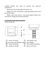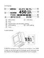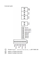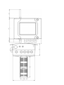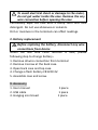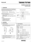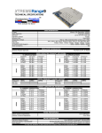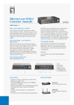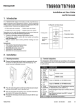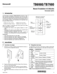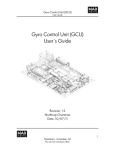
1
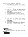
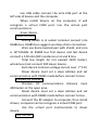
VAT series controller
and transmitter
Manual
1.
General describe
…………………..
2.
Notice for use
…………………..
3.
Panel & connection
…………………..
1
1
2
introduce
4.
Operate introduce
…………………..
5.
Application introduce
………………….
6.
Communication
………………….
7.
Specification
…………………..
8.
Maintenance
…………………..
9.
Accessory
…………………..
7
12
15
15
16
17
1. General describe
This is a measure temperature, relative humidity,
Carbon dioxide(CO2), Volatile organic compounds
gas(VOC) reading and make it to monitor, control, output
device.
Device is use for indoor flue pipe install. It can choose
LCD display or LED indicate model.
Every measure function can set alarm limit by user. 3
relay can be set to difference alarm action. Analogy
output can choose 4~20mA or 0~5V/0~10V function.
Communication can choose USB, RS485, RF, LAN
connection, all communication use same Modbus
protocol. Power supply can use 12VDC, 24VAC/DC or
110/220VAC.
2. Notice for use
Please follow the manual guide to use device.
Please use the type of power supply that like the mark
on device. Do not connection wrong type power to the
power input terminal. Make sure the power is on the rate
of voltage. Power lead in the disturb can make the
measurement unstable.
Do not operate the device around explosive gas, vapor,
or dust and water.
Do not operate the device when part of case removed.
Disconnect all the wire before open the case.
Make sure the rated voltage and rated current is
suitable before use relay to connect the external
equipment.
Please finish wiring before live wire is on.
Make sure the connection is good between wire and
terminal socket.
When real time clock is not work please follow the
manual to change the memory battery.
3. Panel & Connection Introduce
Panel Introduce:
① Screw of casing
② LCD display area
③ Touch key pad: MENU; ENTER; UP; DOWN;
④ Screw of casing
⑤ Wire output bushing
⑥ Hang iron broad
⑦ Sensor terminal.
LCD display:
①
③
④
⑤
⑦
Menu state
② VOC state
Date
Temperature and Humidity reading
CO2 reading
⑥ VOC reading
Time
Install method:
Install the hanging iron broad on the flue pipe. Then make
a hole on the flue pipe for through sensor terminal. Put
the device into hanging iron broad and turn to upright.
Connect port:
①
②
③
Power input:12V DC/ 24V ACDC / 110V~220V AC
Relay 1 output terminal
Relay 2 output terminal
④
⑤
⑥
⑦
⑧
⑨
⑩
⑪
⑫
⑬
Relay 3 output terminal
LAN port
Ground
Analogy output 1 (Humidity 0~100%RH)
Analogy output 2 (Temperature 0~50°C)
Analogy output 3 (CO2 0~3000ppm)
RS485 B port
RS485 A port
RS485 B port
RS485 A port
4. Operation introduce
When touch "MENU" key, it will enter system setup
menu.
System setup list including: MODE, UNIT, TIME,
Backlight(BLED).
MODE setup list including: CAL, ALAR, SW1, SW2,
SW3, OUT.
|-CAL meaning calibrate function.
|-ALAR meaning alarm function setting.
|-SW1 meaning Relay 1 function setting.
|-SW2 meaning Relay 2 function setting.
|-SW3 meaning Relay 3 function setting.
|-OUT meaning Analogy output function
setting.
UNIT setup can set temperature unit to
Fahrenheit degree or Celsius degree.
TIME setup can set the Date and Time for real
time clock.
BLED setup can set the backlight ON or OFF.
CO2 Buzzer alarm setting:
1、 Press "MENU" key to enter system setting,
Press "UP" or "DOWN" key make it display
"MENU-MODE"
2、 Press "ENTER" key
3、 Press "UP" or "DOWN" key make it display
"MODE-ALAR".
4、 Press "ENTER" key, it display "ALAR--SET"
5、 Press "UP" or "DOWN" key to adjust the alarm
limit.
6、 Press "MENU" several until quit system setting
mode.
CO2 calibration:
1、 Press "MENU" key to enter system setting,
Press "UP" or "DOWN" key make it display
"MENU-MODE"
2、 Press "ENTER" key
3、 Press "UP" or "DOWN" key make it display
"MODE-CAL"
4、 Press "ENTER" key
5、 Press "UP" or "DOWN" key make it display
"CAL-CO2"
6、 Press "ENTER" key, it display "CO2-SET"
7、 Press "UP" or "DOWN" key to adjust the
calibrate current CO2 reading
8、 Press "MENU" several until quit system setting
mode
Temperature calibration:
1、 Press "MENU" key to enter system setting,
Press "UP" or "DOWN" key make it display
"MENU-MODE"
2、 Press "ENTER" key
3、 Press "UP" or "DOWN" key make it display
"MODE-CAL"
4、 Press "ENTER" key
5、 Press "UP" or "DOWN" key make it display
"CAL-TEMP"
6、 Press "ENTER" key, it display "TEMP-SET"
7、 Press "UP" or "DOWN" key to adjust the
calibrate current temperature reading
8、 Press "MENU" several until quit system setting
mode
Humidity calibration:
1、 Press "MENU" key to enter system setting,
Press "UP" or "DOWN" key make it display
"MENU-MODE"
2、 Press "ENTER" key
3、 Press "UP" or "DOWN" key make it display
"MODE-CAL"
4、 Press "ENTER" key
5、 Press "UP" or "DOWN" key make it display
"CAL-RH"
6、 Press "ENTER" key, it display "RH-SET"
7、 Press "UP" or "DOWN" key to adjust the
calibrate current humidity reading
8、 Press "MENU" several until quit system setting
mode
VOC calibration:
1、 Press "MENU" key to enter system setting,
Press "UP" or "DOWN" key make it display
"MENU-MODE"
2、 Press "ENTER" key
3、 Press "UP" or "DOWN" key make it display
"MODE-CAL"
4、 Press "ENTER" key
5、 Press "UP" or "DOWN" key make it display
"CAL-VOC"
6、 Press "ENTER" key to calibrate current VOC
reading to lowest.
7、 Press "MENU" several until quit system setting
mode
Analogy output select: (move the jumper on the PCB at
the same time)
1、 Press "MENU" key to enter system setting,
Press "UP" or "DOWN" key make it display
"MENU-MODE"
2、 Press "ENTER" key
3、 Press "UP" or "DOWN" key make it display
"MODE-OUT"
4、 Press "ENTER" key
5、 Press "UP" or "DOWN" key to choose voltage
output display "OUT-V", or current output
display "OUT-A"
6、 Press "MENU" several until quit system setting
mode
Relay control setting: Relay 1 (SW1), Relay 2 (SW2), Relay
3(SW3)
(Normally limit is meaning up limit, menu is only set
to up limit. If need to use low limit setting, please via
communication to setting.)
1、 Press "MENU" key to enter system setting,
Press "UP" or "DOWN" key make it display
"MENU-MODE"
2、 Press "ENTER" key
3、 Press "UP" or "DOWN" key make it display
"MODE-SWx". (x is meaning 1, 2, 3)
4、 Press "ENTER" key
5、 Press "UP" or "DOWN" key make it display
"SWx-XX". (XX is meaning temperature, RH,
CO2, VOC)
6、 Press "ENTER" key, it display "XX-SET"
7、 Press "UP" or "DOWN" key to adjust the limit
value.
8、 Press "MENU" several until quit system setting
mode
Unit setting:Fahrenheit degree (F) or Celsius degree(C)
1、 Press "MENU" key to enter system setting,
Press "UP" or "DOWN" key make it display
"MENU-UNIT"
2、 Press "ENTER" key
3、 Press "UP" or "DOWN" key to choose
Fahrenheit degree unit display "UNIT-F" or
Celsius degree unit display "UNIT-C"
4、 Press "MENU" several until quit system setting
mode
TIME setting:YEAR, MON, DATE, HOUR, MIN
1、 Press "MENU" key to enter system setting,
Press "UP" or "DOWN" key make it display
"MENU-TIME"
2、 Press "ENTER" key
3、 Press "UP" or "DOWN" key make it display
"TIME-XX". (XX is meaning YEAR, MON, DATE,
HOUR, MIN)
4、 Press "ENTER" key, it display "XX-SET"
5、 Press "UP" or "DOWN" key to adjust the value.
6、 Press "MENU" several until quit system setting
mode
Backlight setting:
1、 Press "MENU" key to enter system setting,
Press "UP" or "DOWN" key make it display
"MENU-BLED"
2、 Press "ENTER" key
3、 Press "UP" or "DOWN" key to set ON display
"BLED-ON" or
OFF display "BLED-OFF"
4、 Press "MENU" several until quit system setting
mode
5. Application:
Power connection
Connect the power on the rated, wire use
16~22AWG.
USB connect
Use USB cable connect the mini-USB port at the
left side of device and the computer.
When install drivers on the computer, it will
recognize a virtual COM port. Use the virtual port
communicate to
slaver device.
RS485 connect
Wiring RS485 A, B socket terminal connect into
RS485 bus. RS485 bus suggest use daisy chain connection.
Wire use 4core twisted-pair with shield, and core
is 18~22AGW. At RS485 bus first device and last device
connect a 120 ohm/1W resistance on A and B line.
Total bus length do not exceed 1200 meters,
whole bus most connect 200 slaver device.
Each device common voltage cannot over -7~12V.
Slaver device must set a slave address and set
communication with RS485 mode before connect to bus.
Wireless RF connect
Wireless RF communication distance most
400meters at the open area.
Slaver device must set a slave address and set
communication with RS485 mode before connect to bus.
Connect the RF adapter to computer, then install
drivers, computer can be recognize a virtual COM port.
Use the virtual port communicate to slaver
device.
LAN connect
Slaver device must set a slave address/IP and
MAC address and set communication with LAN mode
before connect to bus. Then connect the LAN
with LAN socket terminal.
Host can link with TCP protocol 1200 port to slave
device.
Relay output connection and setting
There are 3 channel independent relays. Relay is
dry contact common open type.
Rated voltage max 220VAC, rated current max
10A.
It can be set the relay function and control limit
at t he system setting menu.
When device state is catch the control limit, then
relay will action.
Relay can be set to control by host with
communication command.
Analogy output connection and setting
There are 3 channel of analogy output, first
channel is Humidity output, second channel is
temperature output, third channel is CO2 output.
Analogy output can set to voltage output or
current output, voltage output is 0~10V, current output is
4~20mA.
Temperature: 0℃ is zero scale,50℃ is full scale;
Humidity: 0%RH is zero scale, 100%RH is full
scale.
CO2: 0ppm is zero scale, 3000ppm is full scale
6. Communication protocol
Communication protocol use ModBus, support
LAN, RF(433MHz), RS485, USB.
More detail please read appendix: VAT series
communication protocol.
7. Specification
MODEL
DISPLAY
Operation
Measurement
Accuracy
Sensor
Respond time
USB port
VAT930
VAT830
dot array LCD
Touch key pad set
VAT630
LED indicate
Communicate
set
Temperature: -30 ~ 70℃
Humidity: 0 ~ 100%
CO2: 0 ~ 3000ppm
VOC: 0 ~ 30ppm (analogy bar)
Temperature:
+/0.5℃;
Humidity:+/- 3%RH; CO2:+/- (50ppm
+ 3%)
Humidity: capacitance type; CO2:
Dual channel NDIR sensor
CO2: (T90) < 60s; Temperature and
humidity: 1/e(63%)< 10s, 2m/s flow;
2
VOC:
20m
Indoor,
10ppm
alcohol<1min, smoke <5min
Support
Communication
Option
A:RS485 B:LAN
Analogy output
Option
X:4-20mA Y:0-10V
C:RF
Power supply
Limit set
Option 1:100-220VAC
3:12VDC
User setting
Relay
3 channel
Protocol
RTU-MODBUS/TCP-MODBUS
Power
5W(Max) 3.5W(Average)
Warm-up
2min( first use for 2hours)
Use condition
Store condition
-10~50℃;
0 ~ 95 % (without
condensation)
-40 – 70℃ 0 – 95%RH
Protect level
IP40
Size
135 * 91 * 36 mm
Z:0-5V
2:24VDC/AC
8. Maintenance
This is information of basic maintenance, include
change fuse and battery.
Do not try to repair or calibrate device, except you
have experience at repair or calibrate professional
equipment.
1. Normal clean
To avoid electrical shock or damage to the meter,
do not get water inside the case. Remove the any
wire connection before opening the case
Periodically wipe the case with a damp cloth and mild
detergent. Do not use abrasives or solvents.
Dirt or moisture in the terminals can affect readings.
2. Battery replacement
Before replacing the battery, disconnect any wire
connections from device
When the real time clock function is fault, please
following step to change battery:
1. Remove all wire connection from terminal
2. Remove 4 screw at the back case.
3. Open back case and top case.
4. Change a flesh battery CR1220 3V.
5. Assemble case and screw.
9. Accessory
1. User manual
2. USB cable
3. Hanging iron broad
1 piece
1 piece
1 piece