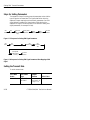
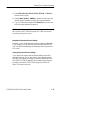
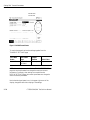
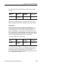
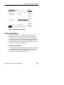
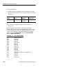
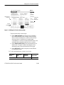
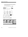
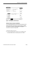
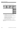
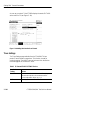
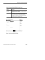
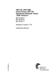
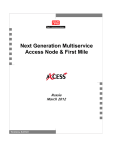
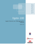
1
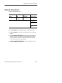
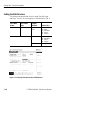
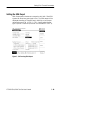
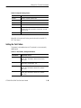
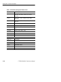
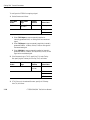
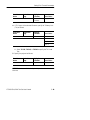
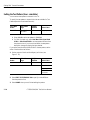
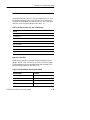
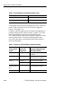
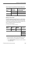
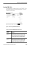
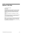
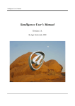
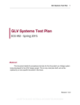
Setting SDH Transmit Parameters
This section describes how to set the transmit rate, specify the AU
under test, set the payload mapping and content, and set the overhead
bytes for SDH signals.
The CTS850 SDH/PDH Test Set contains independent transmitter
and receiver modules. One set of parameters controls the transmitter
module and another set controls the receiver module. You can set the
parameters that control the transmitter independently or you can
choose to link the parameters to the receiver settings.
Figure 3 26:Transmit Settings Menu
CTS850 SDH/PDH Test Set User Manual
3 71
Setting SDH Transmit Parameters
Steps for Setting Parameters
The sequence of steps for setting transmit parameters varies with the
type of signal to be transmitted. The figures that follow show the
sequence of steps required to set the transmit parameters of an SDH
signal without a mapped PDH signal and an SDH signal with a
mapped PDH signal. See the next section for details on setting PDH
signal parameters (for example 2 Mb/s).
Set
Rate
Set Level
(STM 0/1E
only)
Set
Clock
Specify SDH
Structure
Set
Structure
Set
Payload
Set Test
Pattern
Figure 3 27:Sequence for Setting SDH Signal Parameters
Set
Rate
Set
Clock
Set Payload
and Payload
Framing
Set
SDH Structure
Set
TU under
Test
Set Test
Pattern
Figure 3 28:Sequence for Setting SDH Signal Parameters When Mapping a PDH
Signal
Setting the Transmit Rate
To set the transmit rate:
3 72
Press Menu
Button
Select Menu
Page
Highlight
Parameter
TRANSMIT
TRANSMIT
SETTINGS
Transmit Rate
(see Figure 3 29
on page 3 74)
Select Choice
as appropriate
CTS850 SDH/PDH Test Set User Manual
Setting SDH Transmit Parameters
H Select STM-1E or 0E, STM-1, STM-4, STM-0E, or STM-0 to
transmit an SDH signal.
H Select 2 Mb/s, 34 Mb/s, 140Mb/s to transmit a PDH signal. See
the next section for details on setting PDH signal parameters.
H If your CTS 850 test set supports the 45 Mb/s option, there is also
a 45 Mb/s signal available for selection.
NOTE. Even though there are output connectors for both SDH and
PDH signals on the CTS850 front panel, the CTS850 can transmit
only one type of signal at a time.
Independent Transmit and Receive Settings
Generally, you can set the transmit and receive settings independently. For example, you can receive an electrical signal at the STM-1E
or 0E rate while simultaneously transmitting an optical signal at the
STM-4 rate.
Coupling Transmit and Receive Settings
If your application requires that the transmit settings and receive
settings be identical, you can save time by coupling them together.
After they are coupled, any change you make to a parameter on the
TRANSMIT SETTINGS page will also be made to the corresponding setting in the RECEIVE SETTINGS page of the RECEIVE
menu. The inverse is also true.
CTS850 SDH/PDH Test Set User Manual
3 73
Setting SDH Transmit Parameters
Available SDH
transmit rates
Figure 3 29:SDH Transmit Rates
To couple the transmit and receive settings together from the
TRANSMIT SETTINGS page:
Press Menu
Button
Select Menu
Page
Highlight
Parameter
Select Choice
TRANSMIT
TRANSMIT
SETTINGS
Tx/Rx Setup
Coupled
NOTE. When settings are coupled from the TRANSMIT SETTINGS
page, the receive parameters are changed to match the transmit
parameters. Conversely, when settings are coupled from the
RECEIVE SETTINGS page, the transmit parameters are changed to
match the receive parameters.
Notice that the signal status icons, in the upper-right corner of the
display, changed to reflect the coupling of the settings.
3 74
CTS850 SDH/PDH Test Set User Manual
Setting SDH Transmit Parameters
To change transmit and receive settings so that they are no longer
coupled:
Press Menu
Button
Select Menu
Page
Highlight
Parameter
Select Choice
TRANSMIT
TRANSMIT
SETTINGS
Tx/Rx Setup
Independent
Notice that the signal status icons, in the upper-right corner of the
display, changed to indicate that the settings are no longer coupled.
Through Mode
Use Through Mode to monitor a signal without changing it. In
Through Mode, the rate and content of the transmitted signal is that
of the received signal. You cannot make changes to pointers or
timing, overhead bytes, or insert alarms or errors when the CTS850
is in Through Mode. Through Mode does not perform clock recovery
before retransmitting the recovered signal. Through Mode is used for
nonintrusive performance monitoring of the active signal.
To put the CTS850 into Through Mode:
Press Menu
Button
Select Menu
Page
Highlight
Parameter
Select Choice
TRANSMIT
TRANSMIT
SETTINGS
Tx/Rx Setup
Through Mode
To indicate when the CTS850 is in Through Mode, the transmit and
receive icons at the upper-right corner of the display have an arrow
linking them together and the parameters on the TRANSMIT
SETTINGS page are replaced by a message stating that the CTS850
is in Through Mode (see Figure 3 30).
CTS850 SDH/PDH Test Set User Manual
3 75
Setting SDH Transmit Parameters
To take the CTS850 out of Through Mode:
Press Menu
Button
Select Menu
Page
Highlight
Parameter
Select Choice
TRANSMIT
TRANSMIT
SETTINGS
Tx/Rx Setup
Independent
Through Mode icon
Figure 3 30:CTS850 in Through Mode
3 76
CTS850 SDH/PDH Test Set User Manual
Setting SDH Transmit Parameters
Setting the Transmit Clock
To specify the transmit clock:
Press Menu
Button
Select Menu
Page
Highlight
Parameter
Select Choice
TRANSMIT
TRANSMIT
SETTINGS
Transmit Clock
Internal
Recovered
External 2 Mb/s 2
MHz
External 1.5 Mb/s
BITS
H Select Internal to set the transmit clock to the internal clock.
H Select Recovered to use the clock recovered from an incoming
signal.
H Select External 2 Mb/s 2 MHz to use the clock signal from an
external clock input (2 Mb/s or 2 MHz) data timing reference.
Attach an external 2 Mb/s or 2 MHz reference to the External
Clock Input connector on the rear panel.
H Select External 1.5 Mb/s BITS to use the clock signal from an
external 1.5 Mb/s BITS reference.
CTS850 SDH/PDH Test Set User Manual
3 77
Setting SDH Transmit Parameters
Setting the Line Clock Offset
Line Clock offset is used for setting PDH Transmit Parameters.
Range is +100 ppm.
Press Menu
Button
Select Menu
Page
Highlight
Parameter
Select Choice
TRANSMIT
Transmit Settings
Line Clock Offset
Max: +100 ppm
Stress: +20 ppm
Stress 20ppm
Default 0 ppm
User Defined
Setting the value through the front panel knob will change to support
setting the full valid range.
Setting the Transmit Level
Transmit Level is an option for STM 1E and STM 0E. Transmit
Level will not be displayed for other rates.
Press Menu
Button
Select Menu
Page
Highlight
Parameter
Select Choice
TRANSMIT
TRANSMIT
SETTINGS
Transmit Level
0 dB
6dB
H Select 0 dB to set the line level to high.
H Select 6 dB to set the line level to the cross-connect level.
3 78
CTS850 SDH/PDH Test Set User Manual
Setting SDH Transmit Parameters
Specifying the AU to Test
AU under test is only displayed when the input rate is STM 4 and
the signal structure is 1 x AU 4. To designate which AU to test:
Press Menu
Button
Select Menu
Page
Highlight
Parameter
Select Choice
TRANSMIT
TRANSMIT
SETTINGS
AU Under Test
1, 2, 3, 4
CTS850 SDH/PDH Test Set User Manual
3 79
Setting SDH Transmit Parameters
Setting the SDH Structure
This selection sets the structure of the AU under Test (SDH input
rates only). The VC4 4c choice requires a Transmit Rate of STM 4.
Press Menu
Button
Select Menu
Page
Highlight
Parameter
TRANSMIT
Transmit Settings
Structure
STM 4
VC4 4cBulk
AU 4Bulk
AU 4140 Mb/s
TU 3Async
TU 12Async
STM 1
AU
AU
TU
TU
STM 0
AU 3Bulk
Select Choice
4Bulk
4140 Mb/s
3Async
12Async
Figure 3 31:Chosing TU Under Test from SDH Structure
3 80
CTS850 SDH/PDH Test Set User Manual
Setting SDH Transmit Parameters
Figure 3 32:Chosing VC 4cfrom SDH Structure
CTS850 SDH/PDH Test Set User Manual
3 81
Setting SDH Transmit Parameters
TU Under Test
When STM 1 is chosen as the Transmit Rate, and TU 12 or TU 3
chosen as the Structure, the TU under test selection permits the
choice of the following (Selections are mutually exclusive):
exclusive.
TU 12:
TUG3: TUG3:1, TUG3:2, TUG3:3
TUG2: 1,2,3,4,5,6,7
TU 12: 1,2,3
TU 3:
TU 3: 1,2,3
TU3:1, TU3:2, TU3:3
Setting the TU Background Fill
When STM 1 is chosen at the Transmit Rate, and TU 12 or TU 3
chosen as the SDH Structure, the TU Background Fill permits the
user to select the pattern inserted into the inactive TU 12s.
Supported values for TU 12 are PRBS 2^15 1 or IDLE. TU 3
background channels are always filled with the idle pattern.
3 82
CTS850 SDH/PDH Test Set User Manual
Setting SDH Transmit Parameters
Setting the SDH Ouput
SDH Output permits the test set to transmit a valid, bulk filled SDH
signal when the primary test signal is PDH. The SDH output will be
displayed whenever the Transmit Rate is 140 Mb/s or less. Output
rate selections are STM 4, STM 1, STM 0 and Disabled. Output
type is Optical or Electrical (Electrical is not available for STM 4).
Figure 3 33:Choosing SDH Output
CTS850 SDH/PDH Test Set User Manual
3 83
Setting SDH Transmit Parameters
Setting the Payload Structure
Payload sets the signal generation base rate. Because of the number
of selections available, the rate and framing parameters have been
split. If the payload rate is not the same as the mapping (SDH) or
transmit (PDH) rate, then multiplexing is implied.
Table 3 7:TX Rates and Structures
TX Rate
TX Structure
Multiplexing combinations
STM 4
STM 1
VC4 4c(only for STM 4)
AU 4
TU 12
TU 3
140 Mb/s
Bulkfill (Equipped or Unequipped
only)
2Mb/s, 64k
34Mb/s, 8Mb/s, 2Mb/s, 64k
140, 34, 8, 2 Mb/s, 64k
STM 0
AU 3
Bulk Equipped& Unequipped
140 Mb/s
Not Applicable
34Mb/s, 8Mb/s, 2Mb/s, 64k
34 Mb/s
45 Mb/s
Not Applicable
34 Mb/s, 8Mb/s, 2 Mb/s, 64k
2 Mb/s
Not Applicable
2Mb/s, 64k
Bulk fill of a TU 12, TU 3 or VC4 4c is not supported.
To set the payload:
3 84
Press Menu
Button
Select Menu
Page
Highlight
Parameter
Select Choice
TRANSMIT
TRANSMIT
SETTINGS
Payload
As appropriate
CTS850 SDH/PDH Test Set User Manual
Setting SDH Transmit Parameters
Table 3 8:Payload Framing/ Source
Payload
Allowable choices
140 Mb/s
Framed, Unframed, External Add
34 Mb/s
Framed, Unframed, External Add
45 Mb/s
C Bit,M13, Unframed
8 Mb/s
Framed, Unframed
2 MB/s
Unframed, External Add Balanced, External Add
Unbalanced, PCM 30 CAS/CRC, PCM31 CRC, PCM 30
CAS, PCM 31
64k
PCM 30 CAS/CRC, PCM31 CRC, PCM 30 CAS, PCM 31
When 64k is the payload, framing can also be set from the 64k Tx
SETTING menu.
Setting the Test Pattern
Test pattern is selectable when the TX payload is not an externally
added signal.
Table 3 9:Test Patterns, Background Patterns
Test Patterns
Applicable choices
PRBS 2^9 1
STM 4;STM 1;STM 0;140Mb/s; 34 Mb/s; 8Mb/s;
2 Mb/s; 64k. Test Patterns: Normal (ITU); Inverted
(Non ITU)
PRBS 2^11 1
140Mb/s; 34 Mb/s; 8Mb/s; 2 Mb/s; 64k. Test Patterns:
Normal (ITU); Inverted (Non ITU)
PRBS 2^15 1
STM 4;STM 1;STM 0;140Mb/s; 34 Mb/s; 8Mb/s;
2 Mb/s; 64k. Test Patterns: Normal (ITU); Inverted
(Non ITU)
PRBS 2^20 1
STM 4;STM 1;STM 0;140Mb/s; 34 Mb/s; 8Mb/s
2 Mb/s; 64k, Test Patterns: Normal (ITU); Inverted
(Non ITU)
CTS850 SDH/PDH Test Set User Manual
3 85
Setting SDH Transmit Parameters
Table 3 9:Test Patterns, Background Patterns (Cont.)
Test Patterns
Applicable choices
PRBS 2^23 1
STM 4;STM 1;STM 0;140Mb/s; 34 Mb/s; 8Mb/s;
2 Mb/s; 64k, Test Patterns: Normal (ITU); Inverted
(Non ITU)
All Ones
STM 4;STM 1;STM 0;140Mb/s; 34 Mb/s; 8Mb/s;
2 Mb/s; 64k
All Zeros
STM 4;STM 1;STM 0;140Mb/s; 34 Mb/s; 8Mb/s;
2 Mb/s; 64k
10101010
140Mb/s; 34 Mb/s; 8Mb/s; 2 Mb/s; 64k
1 in 8
140Mb/s; 34 Mb/s; 8Mb/s; 2 Mb/s
8 bitfixed
STM 4;STM 1;STM 0;140Mb/s; 34 Mb/s; 8Mb/s;
2 Mb/s
16 bitfixed
140Mb/s; 34 Mb/s; 8Mb/s; 2 Mb/s
24 bitfixed
140Mb/s; 34 Mb/s; 8Mb/s; 2 Mb/s
TS Idle
64k
1020 Hz 0 dBm
64k
Background Patterns
3 86
PRBS 2^23 1
34Mb/s; 8Mb/s
PRBS 2^20 1
34Mb/s; 8Mb/s
PRBS 2^15 1
34Mb/s; 8Mb/s; 2 Mb/s
All Ones
34Mb/s; 8Mb/s; 2 Mb/s
All Zeros
34Mb/s; 8Mb/s; 2 Mb/s
10101010
34Mb/s; 8Mb/s; 2 Mb/s
CTS850 SDH/PDH Test Set User Manual
Setting SDH Transmit Parameters
Selecting the Tx/Rx Setup
Tx/Rx Setup permits the operator to couple Transmit and Receive
settings, or select Through Mode. When coupled mode is selected,
from the Transmit Setting menu, applicable Transmit Settings are
copied to the Receive side of the tester.
Mapping a PDH Signal
To map a tributary signal, you first set the SDH Structure to the
appropriate PDH mapping (as described in the previous section).
When mapping a signal, you must also specify the payload. The
payload can be either an external signal connected to the appropriate
IN connector on the front panel or an internally generated signal.
When you use the TU12 Floating Async or TU3 Floating Async
mapping, you must also specify the tributary unit under test and
payload (see next Figure).
Figure 3 34:Mapping a Tributary Signal
CTS850 SDH/PDH Test Set User Manual
3 87
Setting SDH Transmit Parameters
To configure the CTS850 for mapping a signal:
1. Set the Structure as follows:
Press Menu
Button
Select Menu
Page
Highlight
Parameter
Select Choice
TRANSMIT
TRANSMIT
SETTINGS
Structure
TU12 Async
TU3 Async
140 Mb/s
H Select TU12 Async to map an externally supplied or
internally generated 2 Mb/s or 64k signal to the transmitted
signal.
H Select TU3 Async to map an externally supplied or internally
generated 34 Mb/s, 45 Mb/s, 8 Mb/s, 2 Mb/s or 64k signal to
the transmitted signal.
H Select 140 Mb/s to map an externally supplied or internally
generated 140Mb/s, 34 Mb/s, 45 Mb/s, 8 Mb/s, 2 Mb/s, or 64k
signal to the transmitted signal.
2. If the Structure is set to TU-12, specify the TU Under Test by
first specifying the Tributary Unit Group (TUG) as follows:
Press Menu
Button
Select Menu
Page
Highlight
Parameter
TU Under Test
(TUG3 #n)
Select Choice
TUG3 #1
TUG3 #2
TUG3 #3
All TU12s
3. If TU12 Async is the selected Structure, specify the Tributary
Unit (TU) as follows:
3 88
CTS850 SDH/PDH Test Set User Manual
Setting SDH Transmit Parameters
Press Menu
Button
Select Menu
Page
Highlight
Parameter
TU Under Test
(TU12 #n)
Select Choice
as appropriate
4. If TU3 Async is the selected Structure, specify the Tributary Unit
(TU) as follows:
Press Menu
Button
Select Menu
Page
Highlight
Parameter
Select Choice
TU3
TU3 #1
TU3 #2
TU3 #3
All TU 3
H Select TU3 #1, TU3 #2, or TU3 #3 to specify the TU Under
Test.
5. Specify the payload as follows:
Press Menu
Button
Select Menu
Page
Highlight
Parameter
Select Choice
Payload
as appropriate
NOTE. The choices available for Payload depend on the selected
Structure.
CTS850 SDH/PDH Test Set User Manual
3 89
Setting SDH Transmit Parameters
Setting the Test Pattern (User selectable)
You can select a test pattern to transmit in the TU.
To specify the test pattern to transmit (the choices available for Test
Pattern depend on the selected Structure):
Press Menu
Button
Select Menu
Page
Highlight
Parameter
Select Choice
TRANSMIT
TRANSMIT
SETTINGS
Test Pattern
as appropriate
H Select 1 in 8 to set the test pattern to 10000000.
H For PDH Payloads only, select User Word 8 bit, User Word
16 bit, or User Word 24 bit to set a test pattern different from
the preset choices. If you choose User Word, the test pattern
description changes to display the byte selected.
If you select User Word 8 bit/16 bit/24 bit for the test pattern, set the
value of the User Word as follows:
1. Set the contents of the User Word Byte(s) as follows (see
Figure 3 35):
Press Menu
Button
Select Menu
Page
Highlight
Parameter
Select Choice
Test Pattern
Set to 00000000
Set to 11111111
Default 10101010
EDIT BYTE/
Edit XX bits
2. Select EDIT BYTE/Edit XX bits to specify a value different
from the preset choices.
3. Select DONE when you are finished editing the pattern.
3 90
CTS850 SDH/PDH Test Set User Manual
Setting SDH Transmit Parameters
Figure 3 35:Editing the User Word Byte
Setting Overhead Bytes
To stress test a network, you sometimes need to simulate errors or
alarms. Use the controls on the Defects & Anomalies page of the
TRANSMIT menu to simulate errors or alarms. As an alternative,
you can edit the transport overhead and path overhead bytes directly
to simulate errors, alarms, and create other stress conditions. This
section describes how to use the SECTION OVERHEAD and PATH
OVERHEAD pages to edit overhead bytes.
How to Edit an Overhead Byte
The following procedure applies to editing either section overhead or
path overhead bytes. However, when editing path overhead bytes,
you must specify which overhead you want to edit (VC4, VC3, or
VC12) before you can edit the overhead bytes.
CTS850 SDH/PDH Test Set User Manual
3 91
Setting SDH Transmit Parameters
To edit overhead bytes:
1. Display the section overhead as follows, then select the columns
you wish to edit. Press MORE 2 of 2 to see the Section Overhead
Page choice.
Press Menu
Button
Select Menu
Page
TRANSMIT
Section Overhead Showing
Overhead for
Highlight
Parameter
Select Choice
as appropriate
2. Turn the knob to highlight the byte you want to edit. See
Figure 3 36.
When editing the S1 byte (shown in next figure), entering the
following bits will result in the corresponding label in the line on the
Section Overhead menu called Sync. Status Message (shown in next
figure). This message line, showing the assignment of bit patterns,
appears in both the Transmit menu and, and the Receive menu
under the Section Overhead tab.
S1 bits b5 b8
Sync. Status Message
0000
0001
0010
0011
0100
0101
0110
0111
1000
1001
1010
1011
Quality Unknown
Reserved
G.811 PRC
Reserved
G.812 transit
Reserved
Reserved
Reserved
G.812 local
Reserved
Reserved
G.813 SETS
(Synchronous Equipment Timing Source)
Reserved
Reserved
Reserved
Do not use
1100
1101
1110
1111
3 92
CTS850 SDH/PDH Test Set User Manual
Setting SDH Transmit Parameters
Bytes you can
never edit
Cannot edit
because
alarm is set
S1 byte
selected to
edit
Figure 3 36:Editing the S1 Section Overhead Byte
There are several ways to edit the byte:
H Select Reset Overhead to set all bytes in the overhead to
their individual default values. However, Reset Overhead
does not remove simulated error conditions that have been
set using controls in the Defects & Anomalies page.
A simulated error condition overrides the default value of the
overhead byte that signals that particular error condition.
H Select Default (XXXXXXXX) to set the selected byte to its
default value. The specific default value depends on the
selected byte and on the rate and structure of the signal.
H Select EDIT BYTE to define the byte as a value different
from the preset choices.
3. To edit the selected byte to a value of your choice:
Press Menu
Button
Select Menu
Page
Highlight
Parameter
Select Choice
EDIT BYTE
CTS850 SDH/PDH Test Set User Manual
3 93
Setting SDH Transmit Parameters
H Define your own byte with the buttons next to 1 and 0. Use
the left and right arrow buttons to move the cursor from one
bit to the next. See Figure 3 37.
H When you finish editing the byte, select DONE.
Figure 3 37:Editing an Overhead Byte
Editing the VC4, VC3, and VC12 Overhead Bytes
To edit the VC4, VC3 or VC12 overhead bytes:
Press Menu
Button
Select Menu
Page
Highlight
Parameter
Select Choice
RECEIVE
PATH
OVERHEAD
Overhead View
VC4 Overhead
VC3 Overhead
VC12 Overhead
3 94
CTS850 SDH/PDH Test Set User Manual
Setting SDH Transmit Parameters
NOTE. The choices available depend on the signal Structure.
If the signal Structure is set to TU-12, you can edit the V5, N2, and
K4 bytes after displaying the VC12 Overhead. The J2 trace byte is
fixed and cannot be edited. Note that only bits 5, 6, and 7 (the signal
label bits) of the V5 byte are editable. See Table 3 10.
Table 3 10:Choices for Bits 5, 6, and 7 of the V5 Byte
Choice
Unequip (000)
Equipped (001)
Async (010)
Bit Sync(011)
Byte Sync(100)
Reserved (101)
TSS4 (110)
VC AIS
Bytes You Cannot Edit
Certain bytes in the section overhead and path overhead cannot be
edited in the SECTION OVERHEAD or PATH OVERHEAD pages.
These uneditable bytes have calculated values that are based on the
payload and signal structure (see Table 3 11).
Table 3 11: Overhead Bytes That Cannot Be Edited
Overhead Byte
Function
B1
Section level parity byte
B2
MS level parity byte
B3
Path level parity byte
G1
Path status
CTS850 SDH/PDH Test Set User Manual
3 95
Setting SDH Transmit Parameters
Table 3 11: Overhead Bytes That Cannot Be Edited (Cont.)
Overhead Byte
Function
H1, H2, H3
Identify location of payload
H4
Multiframe indicator
The bytes that cannot be edited are marked with a line of asterisks on
the SECTION OVERHEAD or PATH OVERHEAD pages (see
Figure 3 36 on page 3 93).
In addition, there are bytes you may not be able to edit depending on
parameter settings in the CTS850. As shown in Figure 3 36, a short
text string replaces the binary values in the byte field of the
SECTION OVERHEAD and PATH OVERHEAD pages when a byte
cannot be edited. Table 3 12 shows the affected bytes, the text
string, and a description of the parameter setting that prevents the
byte from being edited.
Table 3 12:Bytes You Cannot Edit Due to Parameter Settings
3 96
Section and
Path Overhead
Byte(s)
Text String that
Replaces the
Binary Values
A1, A2
LOF SET
Loss of Frame Failure is being
simulated
D1, D2, D3
EXT ADD
RS Data Communication Channel External Add is enabled
K1, K2
MS AIS SET
MS AIS is being simulated
RDI SET
MS RDI is being simulated
D4, D5, D6, D7,
D8, D9, D10, D11,
D12
EXT ADD
MS Data Communication Channel External Add is enabled
S1
REI SET
MS REI is being simulated
Parameter Setting Affecting
Byte-Edit Capability
CTS850 SDH/PDH Test Set User Manual
Setting SDH Transmit Parameters
Table 3 12:Bytes You Cannot Edit Due to Parameter Settings (Cont.)
Section and
Path Overhead
Byte(s)
Text String that
Replaces the
Binary Values
Parameter Setting Affecting
Byte-Edit Capability
G1
HP RDI SET
HP RDI is being simulated
HP REI SET
HP REI is being simulated
AU AIS SET
AU AIS is being simulated
All path overhead
bytes set to ones
Editing the J1 Path Trace Byte
The J1 Path Trace Byte carries a fixed-length, 16 or 64-byte string
intended for sending user messages. The Path Trace Byte is a string
consisting of ASCII characters (rather than the ones and zeros used
to edit the other overhead bytes); the 16 byte format includes a CRC
byte. 16 byte and 64 byte are two different formats.
To edit the J1 Path Trace Byte:
1. Display the Path Trace Byte as follows:
Press Menu
Button
Select Menu
Page
Highlight
Parameter
Select Choice
TRANSMIT
PATH
OVERHEAD
J1 byte
Reset Overhead
64 byte Format
16 byte Format
Edit Trace
Default Trace
The text string USER is shown in place of the actual byte value.
There are five ways you can change the Path Trace message.
H Select Reset Overhead to set all bytes in the path overhead to
their default values.
CTS850 SDH/PDH Test Set User Manual
3 97
Setting SDH Transmit Parameters
NOTE. Reset Overhead does not remove simulated error conditions
that have been set using controls in the Defects & Anomalies page.
H Select Null Trace to set all the J1 bytes in the string to the
null character.
H Select Default Trace to set the J1 byte string to the default
string “Tektronix CTS 850 SDH Test Set, hello, bonjour,
guten tag.”
H Select Default 64 Byte to set the J1 byte string to the default
string “Tektronix CTS 850 SDH Test Set, hello, bonjour,
guten tag.”
H Select User Trace to set the J1 byte string to a string you can
enter using the EDIT TRACE function.
H Select Default 16 Byte to set the J1 byte string to the string
“Tek CTS 750” padded with spaces and ending with a
carriage return/line feed.
H Select EDIT TRACE to define your own text string.
2. Select EDIT TRACE to edit the path trace message (see
Figure 3 38).
The string can contain a maximum of 64 characters, including
spaces.
3. Select DONE when you have completed entering the string.
3 98
CTS850 SDH/PDH Test Set User Manual
Setting SDH Transmit Parameters
Figure 3 38:Editing the J1 Path Trace Byte
Adding DCC and User Channel Overhead Bytes
You can add data generated by an external protocol analyzer into the
Data Communication Channel (DCC) and User Channel. The data
from the protocol analyzer is added through the Overhead Add/Drop
Port located on the rear panel. See Appendix G for detailed
information on the port pin assignments.
To add external data into the DCC:
1. Connect an external protocol analyzer to the CTS850 using the
Overhead Add/Drop Port on the rear panel of the CTS850.
CTS850 SDH/PDH Test Set User Manual
3 99
Setting SDH Transmit Parameters
2. To configure the CTS850 to add the external data bytes:
Press Menu
Button
Select Menu
Page
Highlight
Parameter
Select Choice
TRANSMIT
SECTION
OVERHEAD
External Add
None
D1 D3
D4 D12
F1
E1
E2
E1 from Handset
E2 from Handset
H Select None if you do not want to add external data.
H Select D1 D3 to add data, generated by an external protocol
analyzer, to the D1 D3 bytes of the DCC.
H Select D4 D12 to add data, generated by an external protocol
analyzer, to the D4 D12 bytes of the DCC.
H Select F1 to add data, generated by an external protocol
analyzer, to the F1 byte of the DCC.
As soon as you select which bytes to add data to, the CTS850
displays the words EXT ADD as the value for the selected bytes (see
Figure 3 39).
3 100
CTS850 SDH/PDH Test Set User Manual
Setting SDH Transmit Parameters
Figure 3 39:Adding Data into the DCC
To add external data into the User Channel:
1. Connect an external protocol analyzer to the CTS850 using the
Overhead Add/Drop Port on the rear panel of the CTS850.
2. To configure the CTS850 to add the external data byte:
Press Menu
Button
Select Menu
Page
Highlight
Parameter
Select Choice
TRANSMIT
PATH
OVERHEAD
External Add
None
F2
NOTE. The F2 byte cannot be externally generated for VC3
Overhead. However, the F2 byte can be edited from the PATH
OVERHEAD page.
H Select None if you do not want to add external data.
H Select F2 to add data, generated by an external protocol
analyzer, to the User Channel.
CTS850 SDH/PDH Test Set User Manual
3 101
Setting SDH Transmit Parameters
As soon as you select F2, the CTS850 displays the words EXT ADD
as the value for F2 (see Figure 3 40).
Figure 3 40:Adding Data into the User Channel
Trace Settings
The Trace Settings page available from the TRANSMIT Menu
permits Trace Mismatch comparisons. This function is used for
continuity testing. The J0 RS Trace can be chosen from the Section
Overhead page of the TRANSMIT menu.
Table 3 13:Transmit TRACE SETTINGS Choices
Overhead
Testing
3 102
Choices
Trace Select
Selects the trace for which information will be displayed.
Valid selections depend on the current transmit and
receive configurations. Values: J0, J1, J2
TX Trace
This displays the current TX trace.
CTS850 SDH/PDH Test Set User Manual
Setting SDH Transmit Parameters
Table 3 13:Transmit TRACE SETTINGS Choices (Cont.)
Overhead
Testing
RX Trace
Expected Trace
Choices
This displays the current RX trace. The display will be be
updated as new data is received.
This field displays the trace value used for trace mismatch
comparisions. The user may edit the expected value trace,
or copy the value from the value being transmitted or
received. The J0 RS Trace can be chosen in the Section
Overhead page of the TRANSMIT menu.
Figure 3 41:Choosing TRACE SETTINGS
CTS850 SDH/PDH Test Set User Manual
3 103
Setting SDH Transmit Parameters
Signal Labels
The Signal Labels page available from the TRANSMIT Menu
permits selection of the C2 HP Signal Label. The different Signal
Label settings have a dependance on the menus accessible from
TRANSMIT, Transmit Setting, SDH Structure choices (STM 4:
VC4 4c Bulk, AU 4 Bulk, AU 4 140 Mb/s, TU 3 Async 34 Mb/s,
TU 12 Async 2 Mb/s) and the TRANSMIT, Path Overhead, C2
Signal Label choices (Unequipped; Equipped; TUG; TU n; 34
Mb/s; 140 Mb/s; ATM; MAN (DQDB); FDDI; O.181; VC AIS).
The C2 HP Signal Label choice (VC4 Overhead) is enabled when the
HP Signal Label Mismatch Detection choice enabled at the
RECEIVE, Analysis Config page. The C2 LP Signal Label choice
(VC3 Overhead, TU3 Mapped) is enabled when the LP Signal Label
Mismatch Detection choice enabled at the RECEIVE, Analysis
Config page. The C2 V5 Signal Label choice (VC12 Overhead,
TU12 Mapped) is enabled when the LP Signal Label Mismatch
Detection choice enabled at the RECEIVE, Analysis Config page.
Figure 3 42:Choosing SIGNAL LABELS
3 104
CTS850 SDH/PDH Test Set User Manual
Setting SDH Transmit Parameters
Overhead PRBS Test
The Overhead PRBS Test page available from the TRANSMIT Menu
permits PRBS insertion into a selected overhead byte. This function
is used for continuity testing.
Figure 3 43:Choosing OVERHEAD PRBS TEST
Table 3 14:Transmit OVERHEAD PRBS TEST Choices
Overhead
Testing
Choices
TX Overhead
PRBS Test
Sets up PRBS insertion into a selected overhead byte for
continuity testing. Three fields select the byte, PRBS
pattern, and pattern inversion. Byte selections: None,
D1 D3,D4 D12,E1, E2, F1, F2. Patterns: PRBS15,
PRBS20, PRBS23. Inversion: Standard, Inverted.
RX Overhead
PRBS Test
Sets up PRBS insertion into a selected overhead byte for
continuity testing. Three fields select the byte, PRBS
pattern, and pattern inversion. Byte selections: None,
D1 D3,D4 D12,E1, E2, F1, F2. Patterns: PRBS15,
PRBS20, PRBS23. Inversion: Standard, Inverted.
CTS850 SDH/PDH Test Set User Manual
3 105
Setting SDH Transmit Parameters
3 106
CTS850 SDH/PDH Test Set User Manual