1
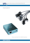
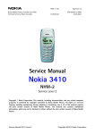
1 (30)
FPS-8
Flashing
User Guide
2 (30)
Contents
Introduction ...........................................................................................................................................................3
Glossary..................................................................................................................................................................4
1
Overview ........................................................................................................................................................5
2
Contents of the Sales package ......................................................................................................................6
3
Minimum PC hardware requirements ........................................................................................................7
4
FPS-8 Usage ...................................................................................................................................................8
4.1 SW Installations ....................................................................................................................................8
4.2 FPS-8 Activation...................................................................................................................................8
4.3 FPS-8 Deactivation ...............................................................................................................................9
4.4 FPS-8 Maintenance with Phoenix.........................................................................................................9
4.5 Phone programming with Phoenix......................................................................................................10
4.5.1 Programming “Dead-Phone” ..................................................................................................11
5
FPS-8 DCT3 setup.......................................................................................................................................12
6
FPS-8 DCT4 setup.......................................................................................................................................15
7
FPS-8 hardware...........................................................................................................................................16
7.1 FPS-8 Front panel ...............................................................................................................................16
7.2 FPS-8 rear panel (Without DCT3 power supply module ACS-10) ....................................................17
7.3 FPS-8 main board................................................................................................................................18
7.3.1 Memory modules....................................................................................................................19
7.4 DCT3 power supply module ACS-10 .................................................................................................23
7.4.1 DCT3 power supply module ACS-10 installation instructions ..............................................24
8
Troubleshooting...........................................................................................................................................28
8.1 Flash programming problems .............................................................................................................28
8.2 Other problems in operation ...............................................................................................................28
8.3 Meaning of the LEDs in the front panel during startup ......................................................................29
8.4 What to do with malfunctioning FPS-8 devices .................................................................................30
3 (30)
Introduction
This is a user guide for installing service sw and phone programming in FPS-8 environment. This
guide will help you with the installation and with the basic problem solving.
NOTE! Pictures in this document may differ from the actual.
4 (30)
Glossary
Algorithm code
Flash programming algorithm code. This code runs in the target system and it
must support used Flash type and phone hw. The prommer box can contain
several algorithm codes; each code supports one or more different Flash
devices. E.g. u_intel.fia supports a number of Intel flash chips.
Application code
Software which FPS-8 prommer box MCU runs.
Asic-Boot
See Bootstrap code
Bootstrap code
Code that resides in target hardware, usually in ASIC ROM or in MCU internal
ROM. Bootstrap code loads secondary bootstrap code into target RAM.
DCT3
Third generation Digital Core Technology.
DCT4
Fourth generation Digital Core Technology.
FLASH
Nonvolatile electronically erasable memory. Both phone and prommer hw
have Flash memory (See prommer main board).
FPS-8
The name of the FLASH prommer
IR
Infrared
TSS4
Test and Service Software 4th Generation
Secondary bootstrap
Second bootstrap code, loads algorithm code into target RAM. Executed in
target hardware. E.g. u_2nd.fia
SRAM
Random access memory, data is lost when power is lost. FPS-8
prommer box can have 64 MB of SRAM (See picture of FPS-8
main board).
WinTesla
Service Software for DCT-3 generation phones
Phoenix
Service Software for DCT-4 generation phones
5 (30)
1
Overview
FPS-8 is a programming device for DCT4 phones. When equipped with power
supply module ACS-10 it can also be used for programming latest DCT-3 phones.
Software for FPS-8 Prommer is delivered in one installation package file. When the new
installation package is installed to the control PC, the Phoenix (or WinTesla) updates the new files
to the FPS-8.
The PCSW controlling the FPS-8 is integrated in the Phoenix (DCT-4 phones) or
WinTesla (DCT-3 phones)
To be able to update the Prommer SW when using WinTesla, a separate prommer
support module (dll) must be installed.
FPS-8 can be equipped with extra memory modules to increase its memory
capacity.
NOTE!
When opening the prommer box or installing power / memory modules
all work Should be done in an ESD – safe environment!
6 (30)
2
Contents of the Sales package
FPS-8 Sales package (0080321) contains following items:
o
FPS-8 FLASH prommer (0750123)
o
Power supply ACF-8 (0680032)
o
CDROM (contains user guide and install sw) (0774271)
o
FPS-8 activation sheet (9359289)
o
Cables:
AXS-4 Serial Cable (connects to PC COM port) (0730090)
Centronics Cable (connects to PC parallel port) (073F000)
Pic 1 Contents of a FPS-8 sales package
7 (30)
3
Minimum PC hardware requirements
o
Processor Pentium 233 Mhz
o
RAM 64 MB
o
Needed disk space 50 - 100 MB
o
Supported Operating Systems:
Windows 95
Windows 98
Windows NT 4.0
Windows 2000
8 (30)
4
FPS-8 Usage
For successful use of FPS-8 also pc sw is needed. All needed sw modules are supplied with the
Phoenix software (Official service software for DCT-4) and with WinTesla sw (official service
software for DCT3 phones).
4.1
SW Installations
Before anything can be done, some installations must be made:
1. Install latest Phoenix software
2. Install latest data package for the phone.
3. Install latest Flash update package.
In the following instructions it is assumed that all these steps are already made.
Flash update package flash_update_01_00_048a.exe and phone sw files nhm75503.010/
nhm75503.01a are used only as an example in the following instructions.
4.2
FPS-8 Activation
Before FPS-8 can be successfully used for phone programming, it must be first activated. Fill in first
“FPS-8 activation request” sheet, which came with FPS-8 sales package and follow the instructions in
the sheet.
When activation file is received (e.g. 71007.in), copy it to BoxActivation –subdirectory under the
Phoenix directory. Start BoxActivation.exe and follow the instructions in the screen.
NOTE! Phoenix should be closed before running BoxActivation.exe.
Pic 2 BoxActivation Welcome screen
9 (30)
4.3
FPS-8 Deactivation
If there is a need to send FPS-8 box to somewhere e.g. for repair, box must be first deactivated.
FPS-8 can be deactivated with BoxActivation sw. Just select Deactivate when asked to choose
function.
Pic 3 Deactivation
4.4
FPS-8 Maintenance with Phoenix
Select”FPS-8 / FPS-8C maintenance” from ”Flashing” menu
If new FPS-8 update package is installed to computer you get a notice:
Pic 4 FPS-8 sw update dialog
Select ”Yes” to update FPS-8 sw.
FPS-8 sw can also be updated by pressing ”Update” button and selecting appropriate fps8upd.ini file.
10 (30)
All files can also be loaded separately to FPS-8. To do this, just press right mouse button in ”Flash box
files” window and select file type to be loaded.
Pic 5 FPS-8 maintenance UI
More information and help can be found from dialogs help (press F1 or Help –button).
4.5
Phone programming with Phoenix
Phone is programmed by selecting “FPS-8 flash” from “Flashing” -menu
11 (30)
Pic 6 FPS-8 flash UI
Press ”Flash” button to start flashing.
It tries first to read phone type and product code to automatically determinate flash files. If reading
fails or appropriate files are not found, ”Flash File Selection” dialog is opened.
Pic 7 Flash file selection dialog
Flash files can be selected by using “Product” and “Product Code” combo boxes or by selecting “Set”
button.
When flash files are set, programming starts when ”OK” button is pressed.
More information and help can be found from dialogs help (press F1 or Help –button).
4.5.1
Programming “Dead-Phone”
Difference in a “Dead-Phone” programming comparing to normal programming is that none of the
needed information can be read automatically. So product and product code must be set manually. See
Pic 7 Flash file selection dialog.
12 (30)
5
FPS-8 DCT3 setup
Needed devices for DCT3 phone programming:
o
PC with WinTesla Service SW (Diskette Code 0774046)
equipped with product specific support dlls.
o
FPS-8 FLASH prommer box (0750123)
o
DCT3 power supply module ACS-10 (0770340)
o
Power Supply ACF-8 (0680032)
o
Cables:
AXS-4 Serial Cable (Connects to PC COM port
(0730090)
Centronics Cable (Connects to PC parallel port)
(073F000)
Product specific cables and adapters, please refer to
service manual for instructions.
Pic 8 FPS-8 DCT3 environment (front)
13 (30)
Pic 9 FPS-8 DCT3 environment (rear)
14 (30)
Pic 10 FPS-8 DCT3 Communicator environment (front)
Pic 11 FPS-8 DCT3 Communicator environment (rear)
15 (30)
6
FPS-8 DCT4 setup
Needed devices for DCT4 phone programming:
o
PC with Phoenix Service SW CD ROM Code (0775311)
o
Product specific data package
o
FPS-8 FLASH prommer box (0750123)
o
Power supply ACF-8 (0680032)
o
Cables:
AXS-4 Serial Cable (Connects to PC COM port)
(0730090)
Centronics Cable (Connects to PC parallel port)
(073F000)
Product specific cables and adapters, please refer to
service manual for instructions.
Pic 12 FPS-8 DCT4 environment
16 (30)
7
7.1
FPS-8 hardware
FPS-8 Front panel
FPS-8 front panel and LEDs are shown like they are when prommer is in normal mode. If
everything is OK, prommer should be in this state after power is connected.
Connectors:
Phone service cable connector
DCT-4 power output connectors for DCT-4 service battery
Main fuse (check if no leds are lit on)
Smart card connector (Not used!)
Infra Red module connector
17 (30)
7.2
FPS-8 rear panel (Without DCT3 power supply module ACS-10)
Connectors:
Parallel input (Centronics)
Phone connector
Serial input (RS232)
PWR (power connector)
Pic 13 FPS-8 rear panel
18 (30)
7.3
FPS-8 main board
Prommer main board has 8 MB SRAM and 16 MB Flash memory for MCU file storing.
The mainboard has a socket for add-on memory modules:
SRAM module SF12 (8 MBytes), 0080346
FLASH module SF13 (64 MBytes), 0080347
The mainboard has also a socket (Pic 24 DCT3 power supply module (ACS-10) connector) for DCT3
power supply module ACS-10.
Pic 14 FPS-8 mainboard
19 (30)
7.3.1
Memory modules
Additional Memory modules are needed when bigger than 8MB files are needed program to the phone
(more SRAM needed) or there is need to store several MCU files in to the FPS-8 (more flash memory
needed). (SRAM module (8MB) SF12, 0080346 and FLASH module (64MB) SF13, 0080347)
Additional SRAM and Flash modules can be plugged into the FPS-8 mother board to extend the
storage capability. The SRAM memory can be expanded up to 64MBytes (8 SF12 cards stacked to the
connector). The FLASH memory can be expanded up to 512MBytes (8 SF13 cards stacked to the
connector). Size of SF12 SRAM add-on module is 8 MBytes and SF13 FLASH module 64 MBytes.
NOTE! Enclosure of FPS-8 limits the number of pieces to 5.
Figure 1 Example of possible memory combinations
Pic 15 SRAM memory module (8MB) (SF12, 0080346)
Pic 16 Flash memory module (64MB) (SF13, 0080347)
20 (30)
7.3.1.1 Memory module installation instructions
NOTE!
When opening the prommer box or installing power / memory modules all
work should be done in an ESD – safe environment!
Step1: power off FPS-8. FPS-8 has to be powered off when mounting memory modules or DCT-3
power supply ACS-10 module. Mounting modules with power supply connected may cause permanent
damages!
Step2: open four crosshead screws (Phillips screws) from rear side of the FPS-8 box.
Step3: carefully remove rear panel (Pic 13 FPS-8 rear panel) and the cover .
Step4: take out SF12 or SF13 from the package (Pic 21 SRAM & FLASH memory sales packages)
and attach it to (Pic 17 Memory extension connector) memory extension connector. Make sure that
memory card screw holes are positioned along with screws on the board correctly (Pic 18 Mounting
memory module). Press directly downwards as far as memory card can go. Make sure that memory
card connector is attached properly with main board memory extension connector!
Step5: Take two plastic screws that came along the add-on memory package and drive them in to the
two other screws.
Step6: put cover and rear panel back and close four crosshead screws (Phillips screws)
Pic 17 Memory extension connector
21 (30)
Pic 18 Mounting memory module
Pic 19 SRAM memory module installed.
22 (30)
Pic 20 FLASH memory card installed above SRAM memory card.
Pic 21 SRAM & FLASH memory sales packages
23 (30)
7.4
DCT3 power supply module ACS-10
If FPS-8 prommer box is wanted to be used for programming DCT3 phones, additional DCT3 power
supply module ACS-10 is needed to provide correct current and voltage levels. FPS-8 add-on rear
panel
Pic 22 DCT3 power supply module ACS-10 from inside
Pic 23 DCT3 power supply module ACS-10 outside
24 (30)
7.4.1
DCT3 power supply module ACS-10 installation instructions
DCT3 power supply module ACS-10 will replace original rear panel.
Step1: power off FPS-8. FPS-8 has to be powered off when mounting memory modules or DCT-3
power supply ACS-10 module. Mounting modules with power supply connected may cause permanent
damages!
Step2: open four crosshead screws (Phillips screws) from rear side of the FPS-8 box.
Step3: carefully remove original rear panel (Pic 13 FPS-8 rear panel).
Step4: Connect wire from ACS-10 panel to the FPS-8 connector (Pic 24 DCT3 power supply module
(ACS-10) connector and Pic 25 DCT3 power supply module (ACS-10) wire connection).
Step5: Slide ACS-10 panel in to the socket like in Pic 26 DCT3 power supply module (ACS-10)
installation 1and Pic 27 DCT3 power supply module (ACS-10) installation 2.
Step6: close four crosshead screws (Phillips screws).
Pic 24 DCT3 power supply module (ACS-10) connector
25 (30)
Pic 25 DCT3 power supply module (ACS-10) wire connection
26 (30)
Pic 26 DCT3 power supply module (ACS-10) installation 1
27 (30)
Pic 27 DCT3 power supply module (ACS-10) installation 2
28 (30)
8
8.1
Troubleshooting
Flash programming problems
Symptoms: Flashing fails when proper cables are not used between FPS-8 and phone.
Possible error codes: many different errors during flash programming.
Cure: Use only shielded cable between FPS-8 and phone (e.g. XCS-4, code 0730178)
Symptoms: The phone does not go to flash mode and the flashing does not start at all.
Possible error codes: error C102 or error 0x8004C102.
Cure:
- Use the newest available FPS-8 Application and Algorithm files. Check the cables and connectors between FPS-8
and phone.
Symptoms: The flashing attempt fails with error code A407 or 0x8004A407. This error can mean that:
-FPS-8 is not activated
-FPS-8 is activated with a wrong activation file
-FPS-8 is not powered off / on after activation
-the activation process has failed for some reason
Cure: Check that you have a right activation file. The number in the file name must match with the serial number
of FPS-8.
- Check that the Phoenix is not running when you run the activation program.
- Disconnect the power plug from FPS-8 for a while after the activation is completed.
8.2
Other problems in operation
Symptoms: Although all cables are connected, FPS-8 seems not to be ON.
Cure: Check main fuse (front panel) or AC adapter.
Symptoms: FPS-8 does not respond when the user opens new connection from the Phoenix. Error window " Open
connection failed...." is displayed.
Cure:
- The COM port you are using may be open already or used by another program e.g. PC suite or another Phoenix.
So close that program first and try again.
- If above did not help, then the COM port may be broken, try another PC.
-If any above did not help, contact FPS-8 service!
Symptoms: The loading of files to FPS-8 fails. FPS-8 or/and Phoenix freezes in the middle of file transfer.
Cure: Check that you use a proper Centronics cable between PC and FPS-8. The proper cable has text "... 12841994 compliant". The Centronics cables shipped with the old FPS-4 devices have no text at all.
NOTE! Do not use FPS-4 Centronics cables with FPS-8.
29 (30)
8.3
Meaning of the LEDs in the front panel during startup
Disconnect all cables from FPS-8. Connect power plug to "POWER 5.5 - 8VDC" connector. Inspect the mode leds
while FPS-8 is starting. The leds in the front panel should flash as follows:
ON
PWR
+----------------------------------------------------------|
OFF --+
ON
MODE1
OFF ------------------------------------------------------------ON
MODE2
+--------+
+--------+
| 2.5s | 1.5s | 3.5s |
OFF --------+
+--------+
+-------------------------
ON
+---+
+-----------------------OUTPUT 4V
|
|
|
OFF -------------+
+------------------+
|
1
|
2
|
3
|
4
|
5
Events:
1) Power plug is connected to FPS-8
2) FPS-8 starts running the code from the Boot flash
3) FPS-8 has executed the startup self tests and starts running the
Application code
4) FPS-8 is now running the code from the Application flash
and starts to load the code to the FPGA chip
5) FPGA is now successfully loaded and FPS-8 is waiting for commands
from the PC
30 (30)
8.4
What to do with malfunctioning FPS-8 devices
If trouble shooting does not help then fill in Repair Request Note, which comes with the sales package.
NOTE! Deactivate box before sending. See 4.3 FPS-8 Deactivation.