1
Next Generation Multiservice
Access Node & First Mile
Russia
March 2012
TECHNICAL SUPPORT
Contents
Chapter 1 Introduction 1.1 Abstract .................................................................................................................... 1-1 1.2 Tasks ........................................................................................................................ 1-1 1.3 Products ................................................................................................................... 1-2 Chapter 2 Management Configuration 2.1 Management Topology .................................................................................................1 2.2 Configuring Local MP-4100 (CL.2) Management...........................................................2 2.3 Configuring Remote MP-4100 (CL.1) Management .......................................................4 2.4 Configuring Remote ASMi-54L Management ................................................................6 2.5 Configuring OP-108 Management ..............................................................................11 Chapter 3 Ethernet over SDH 3.1 ETH Flow Structure ......................................................................................................1 3.2 Physical Connections ....................................................................................................1 3.3 Configuring MP-4100 CL.1 ...........................................................................................2 3.4 Configuring MP-4100 CL.2 ...........................................................................................3 3.5 Configuring ASMi-54L ..................................................................................................4 3.6 Checking the network utilization ..................................................................................5 Chapter 4 Voice over PSN 4.1 Application flow structure .............................................................................................1 4.2 Physical Connections ....................................................................................................1 4.3 Configuring MP-4100 CL.1 ...........................................................................................2 4.4 MP-4100 CL.2 configuration steps ................................................................................4 Chapter 5 Voice over SDH 5.1 Application flow structure .............................................................................................1 5.2 Physical Connections ....................................................................................................1 5.3 MP-4100 CL.1 configuration steps ................................................................................1 5.4 Configuring MP-4100 CL.2 ...........................................................................................2 5.5 Summary ......................................................................................................................2 MAP Workshop
i
Technical Seminar
ii
MAP Workshop
Chapter 1
Introduction
1.1 Abstract
Welcome to the Next Generation Multiservice Access Node & First Mile
workshop. By the end of this workshop you will know how to set up a TDM Access
network to carry different services over different infrastructures using a dumb
terminal or Telnet. You will gain the knowledge of how to prepare, install and
configure a TDM/PSN application based on the multiservice access node MP4100.
Two different phases of MP-4100 will be used in this workshop: Phase 2
(MP-4100 CL.1), which can be controlled by means of menu accessible through
ASCII terminal or Telnet; and Phase 3 (MP-4100 CL.2), which has a completely
different management approach – Telnet or ASCII terminal using RAD Command
Line Interface (CLI). Since this concept is relatively new on the RAD products,
please refer to the CLI explanation in the end of this chapter before starting
configuration. For a deeper explanation you can refer to the User Manual,
“Command Tree” section (page 3-12).
1.2 Tasks
In the table below you will find the different tasks ahead of you.
Chapter
Tasks
Participating Devices
2
Management Configuration
via Terminal
MP-4100; ASMi-54L; OP-108
Task 2
3
ETH over SDH
MP-4100; ASMi-54L; OP-108
Task 3
4
Voice over PSN
MP-4100
Task 4
5
Voice over SDH
MP-4100
Task 5
6
STM-4 Ring Application
MP-4100
Task 1
MAP Workshop
1-1
Technical Seminar
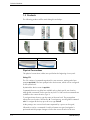
1.3 Products
The following products will be used during this workshop:
Megaplex-4100
OP-108C
ASMi-54
CL.1 / CL.2
ASMi-54C
M8E1
VC-8/FXS
MPW-1
Ringer-2100
OP-108
Physical Connections
The physical connections (cables) are specified at the beginning of every task.
Using CLI
The CLI consists of commands organized in a tree structure, starting at the base
prompt mp4100#. The base prompt is the device name, which can be configured
on the system level.
By default the device name is mp4100.
Commands that are not global are available only at their specific tree location,
while global commands can be typed at any level. To find out what commands are
available at the current location, type ?.
To navigate down the tree, type the name of the next level. The prompt then
reflects the new location, followed by #. To navigate up, use the global command
exit. To navigate all the way up to the root, type exit all.
At the prompt, one or more level names separated by a space can be typed,
followed (or not) by a command. If only level names are typed, navigation is
performed and the prompt changes to reflect the current location in the tree.
1-2
MAP Workshop
Technical Seminar
If the level names are followed by a command, the command is executed, but no
navigation is performed and the prompt remains unchanged.
To use show commands without navigating, type show followed by the level
name(s) followed by the rest of the show command.
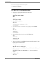
In the example below the levels and command were typed together and therefore
no navigation was performed, so the prompt has not changed.
mp4100# configure port ppp 5/1 bind e1 5/1
mp4100# configure port ppp 5/2 bind e1 5/2
mp4100# configure port ppp 5/3 bind e1 5/3
mp4100# configure port ppp 5/4 bind e1 5/4
mp4100# exit all
In the following example, the levels were typed separately and the navigation is
reflected by the changing prompt.
mp4100#
mp4100# configure
mp4100>config# port
mp4100>config>port# ppp 5/1
mp4100>config>port# ppp(5/1)# bind e1 5/1
mp4100>config>port# ppp(5/1)#
You can type only as many letters of the level or command as required by the
system to identify the level or command, for example you can enter config manag
to navigate to the management level.
In addition to being the default prompt, the # symbol also indicates a static or
already configured entity. The $ symbol indicates a new dynamic entity that takes
several commands to configure. After the configuration is completed, it must be
activated by using the no shutdown command, as shown in the following
example.
mp4100# configure port logical-mac 5/1
mp4100>config>port>log-mac(5/1)$ bind mlppp 5/1
mp4100>config>port>log-mac(5/1)$ no shutdown
mp4100>config>port>log-mac(5/1)$ commit
The shutdown command disables a hardware element (such as a port), while no
shutdown enables/activates it.
The commit command updates the candidate database to the running database
without saving it.
The save command is used to save the user configuration.
CLI commands have the following basic format:
MAP Workshop
1-3
Technical Seminar
command [parameter]{value1 | value2 | … | valuen} [optional parameter
<value>]
where:
{} Indicates that one of the values must be selected
[] Indicates an optional parameter
<> Indicates a value to be replaced by user text
The following keys are available at any time:
? Lists all commands available at the current level
<Tab> Command autocomplete
<Ctrl-E> Logs out
<Ctrl-U> Erases the line
↑
Displays the previous command
↓ Displays the next command
<Backspace> Deletes character
<Ctrl-C> Interrupts current command
<Ctrl-Z> Returns to the device prompt (root)
The following commands are available at any time and at any level:
echo [<text-to-echo>] Echoes the specified text
exec <file-name> [echo] Executes a file, optionally echoing the commands
help [hotkeys] [globals] Displays general help, or optionally just the
hotkeys and/or global commands
history Displays the command history for the current session (by default the
history contains the last 10 commands)
info [detail] Displays information on the current configuration
tree [detail] Displays all lower command levels and commands accessible from the
current context level
CLI commands can be gathered into text files called scripts. They can be created
using a text editor, by recording the user commands or by saving the current
configuration. The scripts can be imported from and exported to RAD devices via
file transfer protocols.
Although scripts can be created using a text editor, it is recommended to save the
configuration file and then edit it rather than write a script from scratch. The
sequence of the commands is very important and if a script fails during startup at a
certain command, the entire configuration file is discarded.
1-4
MAP Workshop
Chapter 2
Management Configuration
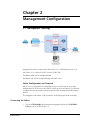
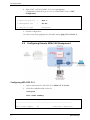
2.1 Management Topology
Management station is connected to MP-4100 CL.2 via ETH-MNG port of CL-A.
MP-4100 CL.1 is reached via DCC over the STM-1 link.
Standalone ASMi-54L is managed inband.
Standalone OP-108 is managed through OP-108C menu.
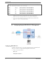
Hosts Configuration via Terminal
Before you can get started on configuring services you will need to set up Host
Management on all devices. In this task you will log on to each device via Terminal,
configure the Host parameters and open up necessary management links between
devices.
The Megaplex-4100 Phase 3 will provide the clock during this whole workshop.
Connecting the Cables
1. Connect ETH Straight cable between Management Station and CONTROLETH port on CL-A, MP-4100 CL.2.
MAP Workshop
1
Technical Seminar
2. Connect LC-LC Fiber cable between SDH port #1 on CL-A, MP-4100 CL.2 and
LINK port #1 on CL-A, MP-4100 CL.1.
3. Connect CH-1 of CBL-DB26-8SHDSL cable (MP-4100CL.2) to the SHDSL port
of the ASMi-54L.
4. Connect SC-LC Fiber cable between OP-108C, Link #1 (MP-4100 CL.1) and
OP-108 standalone unit, Link A.
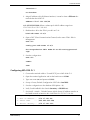
Configuring the Management Station
The Management station is pre-configured with the following IP address:
IP =
172.17.191.90
Mask =
255.255.255.248
Default Gateway = 172.17.191.93
Mask 255.255.255.248 defines a subnet pool with IP address range from
172.17.191.89 to 172.17.191.94.
Overview
When approaching a device for initial configuration it is recommended to set the
devices to default configuration.
2.2
Configuring Local MP-4100 (CL.2) Management
Management access
1. Connect the terminal cable to “Control DCE” port.
2. Open the terminal application and set the baud-rate to 9600.
3. Type the user name (su) and password (1234).
2
MAP Workshop
Technical Seminar
Configuring MP-4100 CL.2
( Reminder: MP-4100 CL.2 configuration is done by CLI
1. Factory Default setup:
file delete startup-config
admin reboot
2. Type yes to confirm the reboot. Wait until you get the prompt again.
3. View the default setting of the router Interface:
configure router 1
info detail
interface
<default interface for host IP ONLY!>
9999
address
0.0.0.1/0
name
"Put your string here"
bind
svi
<the default Service Virtual Interface that connects
router interface # 9999 to bridge port # 9999>
9999
no vlan
no shutdown
<indicates that the interface is in open state by default>
exit
arp-timeout
1200
4. Set the Host IP that will be used to access the local device via IP:
Interface 9999
address 172.17.191.93/29 (the same sub-network as the Management
PC).
5. Add a general Static route to reach the MNG station:
exit
static-route 0.0.0.0/0 address 172.17.191.90
6. Save the configuration :
exit all
commit (updates the configuration changes to the running database)
The following messages must appear:
MAP Workshop
3
Technical Seminar
Result : Warning
<installed modules are not yet configured
in the database, hence the warning>
Slot
CL-B
(W102)MODULE TYPE MISMATCH
Slot
01
(W102)MODULE TYPE MISMATCH
Slot
02
(W102)MODULE TYPE MISMATCH
Slot
03
(W102)MODULE TYPE MISMATCH
save (copies the running configuration to the startup configuration)
7. Verify connectivity (ping/telnet) between the MNG station and MP-4100
(ping 172.17.191.93 –t from MNG station)
2.3
Configuring Remote MP-4100 (CL.1) Management
Configuring MP-4100 CL.2
In order to reach MP-4100 CL.1 from the management station connected to MP4100 CL.2 we have to arrange inband management channel (DCC).
1. Create a new router interface:
exit all
configure router 1
4
MAP Workshop
Technical Seminar
interface 1
no shutdown
2. Assign IP address to this RI (Router Interface). It must be from a different subnetwork than the HOST IP:
address 172.17.191.100/29
Mask 255.255.255.248 defines a subnet pool with IP address range from
172.17.191.97 to 172.17.191.102
3. Bind Interface #1 to the STM-1 port #1 on CL-A:
bind sdh-sonet cl-a/1
4. Open a DCC (Data Communication Channel) on the same STM-1 link for
Management:
exit all
config port sdh-sonet cl-a/1
dcc encapsulation hdlc mode d1-to-d3 routing-protocol
rip2
5. Save the configuration:
exit all
commit
save
Configuring MP-4100 CL.1
1. Connect the terminal cable to “Control DCE” port of MP-4100 CL.1.
2. Open the terminal application and set the baud-rate to 115200.
3. Type user name (su) and password (1234).
4. Set up a Factory Default (Configuration>DB Tools>Load HW)
5. Save the configuration to the database (DB Update - %).
6. Verify Cards installed in the chassis (Inventory > SW/HW rev).
7. Set Host IP + Mask + Default Gateway (Quick Setup). IP address must be on
the SAME network as Interface #1 of MP-4100 CL.2 (172.17.191.99):
Configuration>Quick Setup
1. Host IP Address... (172.17.191.99)
2. Subnet Mask
... (255.255.255.248)
3. Default Gateway... (172.17.191.100)
MAP Workshop
5
Technical Seminar
8. Open a DCC on STM-1 link #1 of CL-A for Management
(Configuration>Physical Layer>CL>CL-A>SDH/SONET>Link 1>DCC
Configuration):
1. In Band Management>
(HDLC)
2. Routing Protocol
>
(RIP 2)
3. Management DCC
>
(D1-D3)
4. Deviation Type
(Standard)
9. Save the configuration.
10. Verify connectivity (ping/telnet) to the MNG station (ping 172.17.191.99 –t).
2.4
Configuring Remote ASMi-54L Management
Configuring MP-4100 CL.2
1.
Open a telnet session to MP-4100 CL.2 (telnet 172.17.191.93).
2.
Verify the installed module in slot #1:
configure
show cards-summary
Slot
Family
Type
HW Ver
SW Ver
---------------------------------------------------------PS-A
6
Power Supply
ps
Undefined
Undefined
MAP Workshop
Technical Seminar
PS-B
Not Installed
--
Undefined
Undefined
CL-A
CL
CL2 622GbE
0.0/ 0.0
3.00B07/ 0
Undefined
Undefined
CL-B Not Installed
--
1
ASMI54C
-
DSL
1
2.73
- - - - - - - - - - - - - - - - - - - - - - - - - - - -
SW versions may be different from the above.
3.
Define the card type in the relevant slot:
slot 1
card-type dsl asmi54c
4.
Open one SHDSL port:
exit
port shdsl 1/1
<refers to slot #1 / port #1 >
no shutdown
5.
Open a PCS (Physical Coding Sublayer) port and bind it to the above SHDSL
port:
exit
pcs 1/1
bind shdsl 1/1
no shutdown
6.
Add an SVI (virtual interface that connects PCS entity to the management
interface)
exit
svi 3
no shutdown
7.
Verify the current Bridge port settings on default Bridge #1:
exit all
configure bridge 1
info detail
MAP Workshop
7
Technical Seminar
# Bridge Port Configuration
port
9997 <Default bridge port for MNG-ETH port of CL-A>
name
" Bridge port 9997"
bind
mng-ethernet
cl-a/1
no shutdown
exit
# Bridge Port Configuration
port
9999 <Default bridge port for the Host IP interface>
name
" Bridge port 9999"
bind
svi
9999
no shutdown
8.
Create a new bridge port in default Bridge #1:
port 3
no shutdown
9.
Bind the new SVI #3 to the new bridge port #3:
bind svi 3
10. Define a classifier profile named “all” that allows all traffic type (classifier
profiles specify the criteria for flows):
exit all
configure flows
classifier-profile all match-all
match all
11. Define a classifier profile named “v100” that allows only traffic tagged with
Vlan 100:
exit
classifier-profile v100 match-all
match vlan 100
8
MAP Workshop
Technical Seminar
12. Define a flow named “mng_to_asmi”, forwarding management traffic from
the MP-4100 to the ASMi-54L:
exit
flow mng_to_asmi
classifier all <Accepts all incoming traffic>
vlan-tag push vlan 100 p-bit fixed 0 <Tag traffic with Vlan
100>
ingress-port svi 3 <Entry point of the Flow>
egress-port pcs 1/1 <Exit point of the Flow>
no shutdown
13. Define a flow named “mng_from_asmi”, forwarding untagged traffic from the
ASMi-54L to the MP-4100:
exit
flow mng_from_asmi
classifier v100
vlan-tag pop vlan
<Accepts only incoming traffic tagged with Vlan
100>
<Untag Vlan 100 from incoming traffic>
ingress-port pcs 1/1
egress-port svi 3
no shutdown
14. Save the configuration:
MAP Workshop
9
Technical Seminar
exit all
commit
save
Configuring ASMi-54L
1.
Connect the terminal cable to “Control DCE” port of ASMi-54L.
2.
Open the terminal application, and set the baud-rate to 115200.
3.
Type the user name (su) and password (1234).
4.
Perform Factory Default (Configuration>System>Factory Defaults).
5.
Set bridge to Aware (Configuration>Applications>Bridge> Vlan Mode).
6.
Press “S” to Save.
7.
Define Host IP (172.17.191.94) and Mask (255.255.255.248)
(Configuration>System>Management>Host).
8.
Tag the Host traffic with Vlan 100
(Configuration>System>Management>Host>Encapsulation):
1. Host Tagging
2. Host VLAN ID [1 - 4094]
(Tagged)
...
3. Host Priority Tag [0 - 7]...
9.
(100)
(0)
Press “S” to Save.
10. Press “Esc”.
11. Press “S” to Save.
Allocating ASMi-54L Bridge Ports
10
MAP Workshop
Technical Seminar
12. Configure a Vlan membership rule, sending traffic tagged with Vlan 100
towards the DSL uplink (port #6), and untagged traffic toward the unit’s Host
(port #1) (Configuration>Applications>Bridge>Vlan Membership):
Use A (ADD) option to configure port tagging
1. Vlan Id[1 - 4094]
...
(100)
2. Egress Tagged Ports
>
(6)
3. Egress Untagged Ports >
(1)
4. Egress Unmodified Port>
(-)
13. Press “S” to Save.
14. Verify connectivity to the MNG station (ping –t 172.17.191.94).
2.5
Configuring OP-108 Management
Configuration steps in MP-4100 CL.1
MAP Workshop
1.
Verify you DON’T have info about the remote OP-108 unit
(Monitoring>Physical Layer>IO>I/O-2 (OP108C)>Remote).
2.
Define the “far end type” as OP108/ETH (Configuration>Physical
Layer>IO>I/O-2 (OP108C)).
3.
Open the local fiber link (Configuration>Physical Layer>IO>I/O-2
(OP108C)>Local>Link).
4.
Save the configuration (DB Update).
11
Technical Seminar
5.
12
Verify you have access to the remote OP-108 unit (Monitoring>Physical
Layer>IO>I/O-2 (OP108C)>Remote):
Device Type
>
(OP108/ETH)
Active Link
>
(Link 1)
Redundancy Status
>
(Not Available)
PS1 Type
>
(ACDC)
PS1 Status
>
(OK)
PS2 Type
>
(None)
PS2 Status
>
(Not Mounted)
Alarm Indication
>
(Normal )
Test Indication
>
(OFF)
MAP Workshop
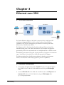
Chapter 3
Ethernet over SDH
3.1 ETH Flow Structure
The Packet (Ethernet) Engine of MP-4100 is a state-of-the-art, multi-port GbE
switching and aggregating block, which enables hardware-based Ethernet
capabilities, such as traffic management, performance monitoring and OAM,
between any of the Ethernet entities.
This Ethernet traffic is flow-based and in this workshop will be terminated by
Internal Ethernet ports of OP-108C and ASMi-54C I/O modules carrying traffic
generated by CPE devices and transferred over multiplexed fiber or SHDSL circuits.
SDH/SONET ports transfer ETH traffic by using Virtual or Contiguous concatenation
(up to 32 VCG per CL.2) with GFP or LAPS and optional LCAS support.
The Ethernet engine flow classification mechanism is based on port (unaware
mode) or VLAN (aware mode with pop/push or preserve capabilities).
3.2 Physical Connections
1. Connect the management PC station Second ETH port (192.168.100.@0) to
the USER-ETH port of the OP-108 standalone unit, using an ETH Straight
cable.
2. Connect ETH Link #1 of the ASMi-54L standalone unit to the ETH port of the
Customer PC station (192.168.100.@1), using an ETH Straight cable.
@ = your group number.
MAP Workshop
1
Technical Seminar
3.3 Configuring MP-4100 CL.1
Since you have IP connectivity to all the units, you should use Telnet for any further
configurations.
1. Set Internal ETH #1 on OP-108C (Configuration>Physical Layer>IO>I/O-2
(OP108C)>Local>Internal>Int-ETH) administrative status to UP.
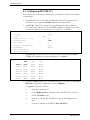
2. Set VCG #1 (Virtual Concatenated Group) administrative status to UP. The
VCG controls the utilization of the bandwidth available on the link to the SDH
network. (Configuration>Logical Layer>CL>VCAT>CL-A>VCG 1).
1.
2.
3.
4.
5.
6.
7.
8.
9.
10.
Admin Status
VC type
LCAS
Number of VCs [1 - 63]
Encapsulation
User Name
Virtual Concatenation
Redundancy
LVC Configuration
GFP Configuration
>
(No)
...
>
...
(Up)
(VC12)
(1)
(GFP)
()
(Yes)
(None)
3. Map VCG #1 to Link #1 of CL-A. The exact location should be TU1/TUG21/TUG3-1 (Configuration>System>Mapping>CL-A>Link 1):
TUG2-1
TUG2-2
TUG2-3
TUG2-4
TUG2-5
TUG2-6
TUG2-7
TU1
VCG1
None
None
None
None
None
None
TU2
None
None
None
None
None
None
None
TUG3-1
TU3
None
None
None
None
None
None
None
4. Configure a Flow between VCG-1 and INT ETH port of OP-108C, including SPVLAN 10 (Configuration>Applications>Flows>Mapping>).
Configuration steps are as follows:
3-2
a.
Press “A” to add flow #1
b.
Go to “Bridge Port List”, and press “A” to add BP 351 (CL-A, VCG 1).
c.
Set the “SP-VLAN” to 10.
d.
Press “S” to save the BP, and “Esc” to return to the Bridge Port List
view.
e.
Press “A” to add the second BP 36 (IO-2, Int-ETH 1).
MAP Workshop
Technical Seminar
f.
BP
351
36
Press “S” to save the BP, and “Esc” to return to the Bridge Port List
view. You should get the following table:
C-VLAN Type C-VLAN ID SP-VLAN Slot Port
Rate BP Name
Unaware
0
10
CL-A VCG 1
2.1Mbps
Unaware
0
0
IO-2 Int-ETH 1 100Mbps
5. Save the configuration.
3.4 Configuring MP-4100 CL.2
1. Configure a VCG and bind/map the relevant VC’s to it:
exit all
configure port vcg cl-a/1
bind
<the first VCG out of 32 possible>
cl-a/1/1/1/1/1 <This path refers to: Common Logic
in Slot A/SDH Port 1/STM-1 Number 1/TUG 3 Number
1 /TUG 2 Number 1/VC-12 Number 1>
vc-vt
no shutdown
2. Configure a GFP (Generic Framing Procedure) and bind the VCG to it:
exit
<the first gfp out of 32 possible>
gfp cl-a/1
bind
vcg
cl-a/1
no shutdown
3. Configure a Logical MAC and bind the GFP to it:
exit
logical-mac cl-a/1
bind
gfp
<the first logical MAC out of 32 possible>
cl-a/1
no shutdown
4. Configure a classifier named “v10” that accepts traffic with Vlan 10 only:
exit all
configure flows classifier-profile v10 match-all
match vlan 10
5. Configure a flow named “data_to_asmi” between the Logical MAC and the
PCS 1/1:
exit
flow
data_to_asmi
classifier
ingress-port
MAP Workshop
v10
logical-mac
cl-a/1
3-3
Technical Seminar
egress-port
pcs
1/1
no shutdown
6. Configure a flow named “data_from_asmi” between the PCS and the Logical
MAC:
exit
flow
data_from_asmi
classifier
v10
ingress-port
egress-port
pcs
1/1
logical-mac
cl-a/1
no shutdown
7. Save the configuration :
commit
save
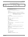
3.5 Configuring ASMi-54L
1. For this configuration use Telnet connection (172.17.191.94)
2. Configure bridge port #2 (connected to ETH port #1) to add Vlan 10 on all
incoming packets (Configuration>Applications>Bridge>Bridge Port):
1.
2.
3.
4.
5.
6.
7.
8.
Bridge Port[2 - 6]
Bind
Egress Tag Handling
Activation
Ingress Filtering
Accept Frame Type
Port VID/Stacking VID[1 - 4094]
Copy Original Priority
Default Priority Tag[0 - 7]
Ingress Tag Handling
TPID (Ether Type)[0 - ffff]
...
>
>
>
(2)
(ETH 1)
(None)
(Enable)
(Disable)
(All)
... (10)
(Disable)
... (0)
>
(None)
... (8100)
3. Press “S” to save.
4. Add a Vlan membership rule, sending traffic tagged with vlan 10 toward the
DSL uplink (port #6), and untagged traffic toward ETH port #1 (port #2)
(Configuration>applications>Bridge>Vlan Membership):
1.
2.
3.
4.
Vlan Id[1 - 4094]
...
Egress Tagged Ports
>
Egress Untagged Ports >
Egress Unmodified Port>
(10)
(6)
(2)
(-)
5. Press “S” to save.
3-4
MAP Workshop
Technical Seminar
6.
Verify connectivity (ping/telnet) between the 2 customer PC’s (IP’s are
192.168.100.@0 and 192.168.100.@1). @ is your workstation number.
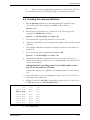
3.6 Checking the network utilization
a.
Run the iperf.exe application on the Management PC second ETH port
(192.168.100.@0) and configure it to Server mode as follows:
iperf.exe –s -u
b.
Run the iperf.exe application on Customer PC (192.168.100.@1) and
configure it to Client mode as follows:
iperf.exe -c 192.168.100.@1 –u –b 2m –t 30
c.
The stream above is producing 2M traffic for 30 seconds.
d.
Check the “Networking” tab on windows task manager, and verify the network
utilization.
e.
Wait till iperf finished the transmission and make sure that a report shows 0%
packets loss.
f.
Now, increase the iperf transmitting bandwidth to 4M:
iperf.exe -c 192.168.100.@1 –u –b 4m –t 30
g.
Wait till iperf finished the transmission and check its report. This time you
should see around 50% packet loss. Try to understand the reason before you’ll
read an answer below:
Although ASMi-54L is providing around 5.7M of SHDSL uplink, we have
only one VC (2M) under our VCG entity.
Increase BW capacity of our application by adding another VC to the existing
VCG
1. On the MP-4100 CL.1 go to (Configuration>Logical Layer>CL>VCAT>CL-A)
and change VCs number to 2.
2. Add the second VC to VCG #1 (Configuration>Logical Layer>CL>VCAT>CLA>VCG 1) and map it to TU1/TUG2-2/TUG3-1:
TUG2-1
TUG2-2
TUG2-3
TUG2-4
TUG2-5
TUG2-6
TUG2-7
TU1
VCG1
VCG1
None
None
None
None
None
TUG3-1
TU2
TU3
None
None
None
None
None
None
None
None
None
None
None
None
None
None
3. Save configuration
MAP Workshop
3-5
Technical Seminar
4. On MP-4100 CL.2, add the same VC to the existing VCG:
configure port vcg cl-a/1
bind
vc-vt
cl-a/1/1/1/2/1
5. Save configuration
6. Run the 4M iperf stream, and make sure the BW utilization is OK.
After this task completion set Factory Default in Megaplex-4100 (CL.2):
file delete starup-config
admin reboot
Type yes to confirm the reboot. Wait until you get the prompt again.
Please take into consideration that this operation will remove the inband
management path and the next tasks configuration should be done with the hyper
terminal.
3-6
MAP Workshop
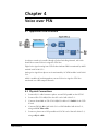
Chapter 4
Voice over PSN
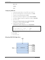
4.1 Application flow structure
In order to transfer voice traffic through a Packet Switching Network, MP-4100
should first convert PCM voice signal to ETH flow.
Digital voice signal coming from FCD-IP that simulates PBX is terminated by M8E1
module in MP-4100 CL.1.
Analog voice signal from phone set is terminated by VC-8FXS module in MP-4100
CL.2.
MPW-1 modules in both Megaplexes convert PCM voice signal to ETH flow
transferred over GBE transport network.
4.2 Physical Connections
MAP Workshop
1.
Connect RJ-11 cable between a phone set and FXS port #1 on the FCD-IP.
2.
Connect CBL-G703-8/RJ45/X to the 8E1 card of MP-4100 CL.1.
3.
Connect channel #1 of CBL-G703-8/RJ45/X cable to E1 Link #1 of the FCDIP unit.
4.
Connect GbE link #1 of MP-4100 CL.1 to GbE link #1 of MP-4100 CL.2,
using an LC-LC fiber cable.
5.
Connect a phone set to FXS port #1 on VC8-FXS card of the MP-4100 CL.2,
using an RJ-11 cable.
1
Technical Seminar
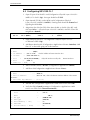
4.3 Configuring MP-4100 CL.1
1. Open E1 port #1 of the 8E1 card (Configuration>Physical Layer>IO>I/O-1
(M8E1)>E1>Link 1 (Up)). Line type should be G.732S.
2. Open Internal DS1 #1 on the MPW card (Configuration>Physical
Layer>IO>I/O-3 (MPW1)>Int-DS1). Framing mode should be Framed and
Signaling should be Yes.
3. Assign time slot #1 of Int-DS1 #1 to time slot #1 on Link 1 of the 8E1 card,
with type Voice (...>Physical Layer>IO>I/O-3 (MPW1)>Int-DS1>Time Slot
Assignment>Manual):
Ts#
TS 01
Slot
IO-1 (M8E1)
Port
Link 1
Ts
1
Type
VOICE
4. Open GbE port #1 on CL.1 (Configuration>Physical Layer>CL>CLA>Ethernet>GBE 1(Up)).
5. Add Router Interface #1 (Configuration>Applications>Router>Interface). Add
Vlan “5” to the traffic going out of this interface:
1. Number[1 - 100]
2. Name
... (1)
... (RI#1)
3. IP Address ... (30.0.0.20) <local IP address of Router Interface #1>
4. IP Mask
... (255.255.255.0)
5. Slot
>
(CL-A(CL1/155GbE))
6. Port
>
(GbE 1)
7. VLAN ID[1 - 4094] ... (5)
<Physical interface used by this
Router Interface>
6. Add a Default Gateway 30.0.0.1 (Configuration>Applications>Router).
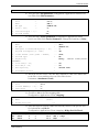
7. Add Peer #1 (Configuration>Applications>Router>Peers):
1. Peer Number[1 - 100]
2. Name
... (1)
... (Peer-1)
3. Peer IP Address
... (30.0.0.10)<this is the Router Interface address of the remote
MP-4100>
4. Peer Next Hop Address ... (0.0.0.0)
8. Add PW #1 (Configuration>Applications>Multi service over PSN>PW).
9. Verify the PW’s General parameters (Configuration>Applications>Multi
service over PSN>PW>General Parameters):
PW Number[1 - 640]
...
Slot
>
Name
...
1. PW Type
>
2. PSN Type
3. Peer Number[1 - 100]
...
4. OAM Mode
5. Out PW Label[1 - 8063]
...
2
(1)
(IO-3)
(PW-1)
(TDMoIP CE)
(UDP/IP)
(1)
(Disabled)
(1)
MAP Workshop
Technical Seminar
6. In
PW Label[1 - 8063]
...
(1)
10. Verify the PW’s PSN parameters (Configuration>Applications>Multi service
over PSN>PW>PSN Parameters):
PW Number[1 - 640] ...
Slot
>
Name
...
PW Type
>
1. TOS[0 - 255]
...
2. Vlan Priority[0 - 7]...
3. Payload Format
(1)
(IO-3)
(PW-1)
(TDMoIP CE)
(0)
(0)
(V2)
11. Verify the PW’s Service parameters (Configuration>Applications>Multi
service over PSN>PW>Service Parameters). Change the Sensitivity to Delay:
PW Number[1 - 640]
Name
PW Type
1. TDM Bytes In Frame(x48 Bytes)[1 - 30]
Payload Size(Bytes)[4 - 1440]
2. Jitter Buffer [usec][2500 - 200000]
3. Far End Type
4. Sensitivity
voice traffic>
5. Voice OOS[0 - ff]
6. Data OOS[0 - ff]
7. OOS Signaling
8. Attachment Circuit
...
...
>
...
...
...
>
(1)
(PW-1)
(TDMoIP CE)
(1)
(48)
(2500)
(E1)
(Delay)
<Relevant for delay sensitive
... (00)
... (00)
>
(Forced Idle)
>
12. Attach the relevant circuit (Time slot #1 of Internal DS1 #1 of the MPW card)
to the PW (...tions>Multi service over PSN>PW>Service
Parameters>Attachment Circuit):
PW Number[1 - 640]
... (1)
1. Slot
>
(IO-3)
2. Int-DS1 Number[1 - 8]... (1)
3. Time Slots
>
(1)
13. Check flow #2 on the Flow mapping table
(Configuration>Applications>Flows>Mapping):
1. Flow
[1 - 250] ...
2. Name
...
3. Bridge Port List
(2)
(RI#1)
[]>
14. Note that this flow has been added automatically between GbE port #1 and
IO-3 (the MPW card) RI #1
(Configuration>Applications>Flows>Mapping>Bridge Port List-Flow2):
BP
359
501
C-VLAN Type C-VLAN ID SP-VLAN
Aware
5
0
CL-A
Aware
5
0
IO-3
MAP Workshop
Slot
Port
Rate
GbE 1 1Gbps
RI#1
---------
3
Technical Seminar
This screen may appear after data base update.
15. Update the configuration.
4.4 MP-4100 CL.2 configuration steps
1. Define the VC-8/FXS and the MPW cards in the system:
configure slot 2
card-type voice vc8fxs
exit
slot 3
card-type pw mpw1
2. Open GbE #1 on the CL-A:
exit all
configure port ethernet cl-a/1
no shutdown
3. Open Internal DS1 #1 on the MPW card. Signaling should be enabled:
exit
ds1 3/1
signaling
no shutdown
4. Open analog port #1 on the voice card, with CAS signaling:
exit
voice 2/1
signaling cas
no shutdown
5. Add a cross connection on the DS0 level between the MPW internal DS1 time
slot #1 to the VC8 analog port #1 :
exit all
configure cross-connect
ds0 ds1 3/1 ts 1 voice 2/1
6. Add a cross connection on the PW level between PW #1 to the MPW internal
DS1 time slot #1:
pw-tdm pw 1 ds1 3/1 time-slots 1
circuit>
<This is the attachment
7. Configure a PW:
exit all
4
MAP Workshop
Technical Seminar
configure pwe
pw 1 type tdmoip-v2 psn udp-over-ip
sensitivity
<PW behavior is now delay sensitive>
peer 1
no shutdown
8. Create Peer #1:
exit all
configure peer 1 ip 30.0.0.20 <this is the Router Interface
address of the remote MP-4100>
9. Configure a new SVI port #5:
exit all
configure port svi 5
no shutdown
10. Configure a Default Gateway on Router #2:
exit all
configure router 2
static-route 0.0.0.0/0 address 30.0.0.1
11. Create Interface #1 on Router #2:
interface 1
address 30.0.0.10/24
12. Bind the new RI to SVI #5:
bind svi 5
13. Add a classifier profile named “v5”, accepting only traffic tagged with Vlan 5:
exit all
configure flows
classifier-profile v5 match-all
match vlan 5
14. Add flow named “voice_to_GbE”, forwarding traffic tagged with Vlan 5 from
SVI #5 to the GbE interface:
exit
flow voice_to_GbE
classifier v5
ingress-port svi 5
egress-port ethernet cl-a/1
no shutdown
MAP Workshop
5
Technical Seminar
15. Add flow named “voice_from_GbE”, forwarding traffic tagged with Vlan 5 from
the GbE interface to SVI #5:
exit
flow voice_from_GbE
classifier v5
ingress-port ethernet cl-a/1
egress-port svi 5
no shutdown
16. Save the configuration:
exit all
commit
save
17. Verify voice connectivity between the 2 phone sets.
6
MAP Workshop
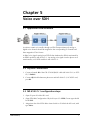
Chapter 5
Voice over SDH
5.1 Application flow structure
In order to transfer voice traffic through an SDH Transport Network, analog or
digital voice channels should be assigned to the corresponding E1 channels and
then mapped to STM-1 frame.
A digital voice signal coming from FCD-IP that simulates the PBX is terminated by
an M8E1 module in MP-4100 CL.1. An analog voice signal from the phone set is
terminated by a VC-8FXS module in MP-4100 CL.2.
5.2 Physical Connections
1. Connect channel #2 of the CBL-G703-8/RJ45/X cable (MP-4100 CL.1) to FCDIP, E1 Link #1.
2. Connect RJ-11 cable between phone set and MP-4100 CL.2, VC-8/FXS card,
port #2.
5.3 MP-4100 CL.1 configuration steps
1. Open E1 port #2 of the 8E1 card.
2. Open PDH #1 (Configuration>Physical Layer>CL>PDH). Frame type should
be G.732S.
3. Assign time slot #1 of PDH #1 to time slot #1 on E1 #2 of the 8E1 card, with
type Voice.
MAP Workshop
1
Technical Seminar
4. Map PDH #1 to TUG3-1/TUG2-1/TU2 on STM-1 link #1.
5. Save the configuration.
5.4 Configuring MP-4100 CL.2
1. Open analog port #2 on the voice card, with CAS signaling.
2. Open E1-i #1 (PDH #1) on CL-A
configure port e1-i cl-a/1
no shutdown
3. Add a cross connection on the DS0 level between E1-i #1 time slot #1 to the
VC8 analog port #2
exit all
configure cross-connect
ds0 e1-i cl-a/1 ts 1 voice 2/2
4. Map E1-i #1 to TUG3-1/TUG2-1/TU2 on STM-1 link #1 (prompting: use cross
connect on the SDH-SONET level between the relevant vc12-vt2 and the E1-i)
sdh-sonet vc12-vt2 cl-a/1/1/1/1/2 e1-i cl-a/1
5. Save the configuration.
6. Verify voice connectivity between the 2 phone sets.
5.5 Summary
You have just completed the Next Generation MAP & First Mile workshop. Now
you are able to prepare and install access applications with data and voice services
extension over GBE and SDH transport networks.
You’ve learnt how to control MAP equipment supported menu or CLI configuration
options by ASCII Terminal or Telnet.
We hope this new knowledge will help you in your daily work.
2
MAP Workshop