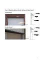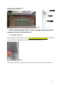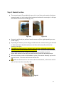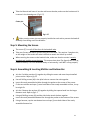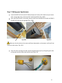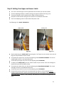
1
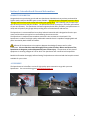
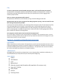
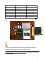
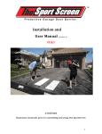
Installation and User Manual (Versi on 1 ) For P309, P312 and P316 ATTENTION Read these materials prior to assembling and using The SportScreen 1 Table of Contents Section 1 ..................................................Introduction & General Information Product Information…………………………………………………………………………………………..3 Accessories………………………………………………………………………………………………………..3 FAQ……………………………………………………………………………………………………………………4 Section 2 .................................................Assembly and Installation Instructions Disclaimer……………………………………………………………………………………….……………....….5 Preparation……………………………………………………………………………………………………..…..5 Tools Needed…………………………………………………………………………………………………….….5 Assembly…………………………………………………………………………………………….………..…5-16 Section 3 .................................................……………..User Warning Information User Warning Information……………………………………………………………………………………………...17 Section 4 .................................................…Care and Maintenance Instructions Cold Weather Protection…………………………………………………………………………………..18 Replacement Parts………………………………………………………………………………………….…18 Safety Checklist/Rules……………………………………………………………………………………….18 Section 5 .................................................……………………Warranty Information Warranty Information……………………………………………………………………………………………………...19 2 Section 1: Introduction & General Information PRODUCT INFORMATION Congratulations on purchasing your brand new SportScreen! We believe that you have purchased the highest quality and most durable sports screen available. The SportScreen is designed to prevent dents, damage, and noise from pucks and/or balls hitting your garage door, while allowing you to improve the skills of both yourselves and your children. The SportScreen allows you to play in the safety and comfort of your own driveway. The SportScreen has been engineered with safety, durability, and performance in mind, and will protect your garage while providing hours of entertainment and exercise. The SportScreen is constructed from heavy-duty industrial materials and is designed to function yearround, and thus does not need to be removed during the winter months. The SportScreen is made of flame-retardant mesh that is also resistant to UV and mold. The SportScreen is made of such high quality and durable materials that it is capable of stopping balls and pucks launched by both children and adults. Safe use of The SportScreen also requires adequate knowledge of setup as well as a few precautions. Please read this manual thoroughly for key points of safety. Misuse and abuse of The SportScreen is dangerous, and could potentially cause serious injury. The purchaser of this piece of equipment is assuming a degree of risk for which The SportScreen Ltd. cannot be held responsible. Read this information thoroughly before allowing The SportScreen to be used and also keep this manual available for your review. ACCESSORIES The SportScreen Ltd. also offers a series of high-quality sports accessories to go with your new SportScreen. For a current listing go to www.thesportscreen.ca 3 FAQ If I leave my SportScreen mounted outside during the winter, will it be affected by the weather? The SportScreen is designed to be able to withstand harsh weather and temperatures. However, we recommend removing snow buildup from the top of your SportScreen to prevent sagging and to maintain proper function. How can I clean my SportScreen and/or valance? All SportScreens and valances can be cleaned up using a mild dish detergent and water. My Sportscreen does not cover my entire 16 foot wide garage door opening. How do I install it for the best coverage and protection possible? A center point should be marked on your mounting surface so that you center The Sportscreen correctly with your garage door when mounting. If your Sportscreen is 16 feet wide that gives you 5 feet of protection on either side of a regulation hockey net and will be plenty of protection when shooting pucks or throwing balls. By design The Sportscreen is made to fit within a 16 foot garage door frame to give it flexibility for different mounting options Can I program a second remote control to work with my Sportscreen? Yes, you can order a second or even a third remote on our website in our accessories section. You can have up to 4 working remotes with one Sportscreen if you want the convenience of having them in your vehicle when you pull in to your driveway. Section 2: Assembly and Installation Instructions DISCLAIMER While it is possible to install and mount The SportScreen yourself, we recommend that customers hire a professional garage door specialist or a general handyman to complete the installation to ensure proper installation and best possible operation of your SportScreen. The SportScreen Ltd. assumes no liability for incorrect installation by customers or third party installers. PREPARATION We suggest that you assemble your SportScreen in your driveway before installation. Additionally, it is recommended that you sweep and clean your driveway before beginning. TOOLS NEEDED Ladders Tape Measure Level Marker/Pencil Robertson (square head) Screwdriver Bit (supplied to US customers only) Power Drill / Drill Bits Safety Glasses Hammer Fastening Screws 4 ASSEMBLY Step 1: Lay Out All Materials Head Roll Assembly B D A G E F C H Middle & Bottom Bar Assembly I K J L PART DESCRIPTION QUANTITY A HEAD ROLL TUBE – MOTOR END 1 B B MOTOR END BRACKET (STAR BRACKET) 1 C C MOTOR END COTTOR PIN 1 D HEAD ROLL TUBE JOINER 1 E HEAD ROLL TUBE – IDLER END 1 F IDLER END 1 G IDLER END BRACKET 1 H IDLER END COTTOR PIN AND HARDWARE 1 I BOTTOM BAR END CAP 2 J MIDDLE BAR END CAP 2 K BOTTOM BAR 2 L MIDDLE BAR 2 5 M SELF DRILLING SCREW 1 N 1 O REMOTE, BATTERY AND REMOTE HOLDER WALL PLUG P MEASURING WIRE 1 Q LIMIT ADJUSTING WAND 1 R WARNING LABEL 1 S MANUAL 1 T SCREEN 1 1 Other N R M T P O Q S Fig 1.2 *** NOTE - WOOD MOUNTING SCREW AND OTHER FASTENERS ARE NOT PROVIDED. FASTENERS CAN BE PURCHASED AT ANY LOCAL HARDWARE STORE. IT IS THE CUSTOMERS RESPONSIBILITY TO ENSURE THE SPORT SCREEN MOUNTING BRACKETS ARE PROPERLY FASTENED TO THE MOUNTING SURFACE. PLEASE CONSULT A PROFFESSIONAL INSTALLER IF NEEDED. 6 Step 2: Mounting Options (Inside, Surface or Under Eaves) Inside Mount Fig 1.9 Surface Mount Fig 1.10 7 Under Eaves Mount *** Fig 1.11 *** Ensure mounting height is 8’10” or lower. For higher mountings, contact customer service for a custom build unit. A) Inside Mount (Fig 1.9) The inside mount can be used for screens that fit inside the garage door opening. The brackets are mounted to the garage door frame at the upper corners (Fig 1.12). Fig 1.12 The wall mount bracket is mounted directly to the wood door frame using 4 woodscrews. 8 B) Surface Mount (1.10) The Surface Mount is used for screens that are mounted directly on the surface of the building (Figure 1.10 & 1.13). Fig 1.13 *** NOTE - WOOD MOUNTING SCREW AND OTHER FASTENERS ARE NOT PROVIDED. FASTENERS CAN BE PURCHASED AT ANY LOCAL HARDWARE STORE. IT IS THE CUSTOMERS RESPONSIBILITY TO ENSURE THE SPORT SCREEN MOUNTING BRACKETS ARE PROPERLY FASTENED TO THE MOUNTING SURFACE. PLEASE CONSULT A PROFFESSIONAL INSTALLER IF NEEDED. Step 3: Head roll Tube Assembly Lay out on a flat surface the head roll tube components (A and E) with (D) being the middle piece. The head roll tube idle end (E), middle section (D) and motor end (A) are supposed to be a tight fit with each other. Connect the pieces of tube, ensuring that the Velcro lines up with each piece (Fig 1.14). Fig 1.14 When the joiner is completely inserted into the tube(s) the assembled tube should be checked to ensure it is straight. This can be done by rolling the tube on a flat surface like the garage floor or the driveway. Once the assembly is straight the tube(s) are attached to the joiners using the self tapping screws that are provided. The tube has pre-marked holes and a power drill is required to install the screws. Tip the head roll tube towards the idler end to empty out any aluminum shavings. Fasten the idler end to the head roll tube with the self tapping screws. The tube has premarked holes. 9 Step 4: Bracket location The measuring wire (P) provided with your unit is a tool that can be used to eliminate a measuring tape. It is to be hooked from bracket-to-bracket with a cotter pin. It will span the distance of the head roll tube (fig 1.15). Fig 1.15.1 Fig 1.15.2 Determine which end you prefer to have the motor at (left or right depending on your power supply) Depending on whether you are doing an inside mount or a surface mount, you will need to fasten the drop-in bracket hardware to the idler end bracket (G) such that the opening is facing up. Provided the measuring wire is relatively level, mark the outside edge location of the brackets as well as hole locations for the fasteners. Note: Ensure that in this area there are no obstructions as this is where the headroll will eventually be mounted. Attach both brackets to the wall, but leave them fairly loose for adjustments later. With one installer at each end and ladders in place, lift the entire assembly up into the desired location. The motor end must be inserted first. Make sure that the wire on the motor end faces downwards, so that water and ice will not funnel into the motor (Fig 1.16). Fig 1.16 10 Take the idle end and insert it into the wall mount bracket, and move the bracket until it is secure in the slotted grove. (Fig 1.17). Cotter pin Fig 1.17 Make sure the cotter pins are properly installed at each end to prevent the headroll assembly from falling out of the brackets. Step 5: Mounting the Screen The screen (T) is to roll off the front of the headroll tube. Take your Screen and loop it up over the front of the tube. This requires 2 people to do, as the weight of the screen will make it difficult to attach the Velcro by oneself. When securing the screen to the headroll tube, make sure that the curtain is evenly attached and straight across the tube. This ensures that when The SportScreen rolls up, it does so evenly. If it is not attached evenly or horizontally, it will NOT roll up properly. Step 6: Assembling & Inserting Mid Bar and Bottom Bar Join the 2 mid bar sections (L) together by sliding the outer rods over the preinstalled joiner section. Refer to fig 1.5 Use self drilling screws (M) in the pilot holes to connect the rods together Insert this newly assembled mid bar through the pocket at the center of the screen. Fit the two mid bar end caps (J) onto both sides of the newly assembled mid bar, it may be a tight fit. Join the 2 bottom bar sections (K) together by sliding the tapered ends into the larger diameter ends. Refer to fig 1.5 Using self drilling screws (M) and the pilot holes attach the bars together Insert this newly assembled bottom bar through the pocket at the bottom of the screen. Using a hammer, tap the two bottom bar end caps (I) onto both sides of the newly assembled bottom bar. 11 Step 7: Wiring your Sportscreen If you would like to have your wire fed through your house, drill a hole into your house from your garage using a minimum 3/8” clearance drill bit (Fig 1.18.2). Once your SportScreen is mounted, take the cord from the end of the motor and feed it through the hole into your garage (Fig 1.18.2). Fig 1.18.1 Fig 1.18.2 Make sure that the wire on the motor end faces downwards, so that water and ice will not funnel into the motor. Fig 1.18.1 Once the wire is through the wall, attach the yellow plug cap (O), wiring the green wire to the green and the other two to either end (Fig 1.19). 12 Fig 1.19 Step 8: Programming your Remote Control Your Sportscreen remote control is already pre-programmed with your Sportscreen motor. Simply install the battery into the back of your remote (Fig 1.20). If you want to add a second, third or fourth remote visit www.thesportscreen.ca Fig 1.20 **If for some reason your remote is not programmed, follow these steps: 1) Unplug unit 2) Hold Up button (5 seconds) 3) Plug unit back in while still holding up button 4) Listen for beeping from motor 5) As motor is beeping, rapidly press up button 13 Step 9: Setting Your Upper and Lower Limits The “limit” sets how high or low the SportScreen will roll when you use the remotes. The limit adjusting wand (P) is used for setting your upper and lower limits (Fig 1.21) The pictures below are the underside of the head roll tube looking up. the power cord should be coming out of the motor on the bottom of the tube There is an adjusting screw on either side of the power cord. The following is for a RIGHT SIDE MOTOR Upper Limit Lower Limit Fig 1.21.1 Fig 1.21.2 Start by adjusting your UPPER LIMIT. By pressing the “up” button on your remote. Your unit will begin to wrap around the head roll tube. To increase your upper limit, turn the limit adjusting wand COUNTER-CLOCKWISE. The screen should begin to travel in the upward direction. To decrease your upper limit, turn the limit adjusting wand CLOCKWISE. To adjust your LOWER LIMIT, press the “down” button on your remote. Your unit will begin to release the screen off the head roll tube. To increase your lower limit, turn the limit adjusting wand COUNTER-CLOCKWISE. The screen will begin to travel in the downward direction. To decrease your lower limit, turn the limit adjusting wand CLOCKWISE. Continue this process until the net is at the desired level. When it is fully lowered, the net should be tight and the bar almost touching the ground, but low enough to stop a hockey puck from sliding under. When it is fully raised up, the bottom bar should be tucked right below the tube. 14 The following is for a LEFT SIDE MOUNT Upper Limit Fig 1.22.1 Lower Limit Fig 1.22.2 Start by adjusting your UPPER LIMIT. By pressing the “up” button on your remote. Your unit will begin to wrap around the head roll tube. To increase your upper limit, turn the limit adjusting wand CLOCKWISE. The screen should begin to travel in the upward direction. To decrease your upper limit, turn the limit adjusting wand COUNTER-CLOCKWISE. To adjust your LOWER LIMIT, press the “down” button on your remote. Your unit will begin to release the screen off the head roll tube. To increase your lower limit, turn the limit adjusting wand CLOCKWISE. The screen will begin to travel in the downward direction. To decrease your lower limit, turn the limit adjusting wand COUNTER-CLOCKWISE. Continue this process until the net is at the desired level. When it is fully lowered, the net should be tight and the bar almost touching the ground, but low enough to stop a hockey puck from sliding under. When it is fully raised up, the bottom bar should be tucked right below the tube. 15 Step 10: Display Warnings Display the warning information sign either inside or near your garage to ensure users remain safe and are aware of any dangers. Section 3: User Warning Information When shooting pucks, please ensure that everyone in the area is wearing a hockey helmet and cage to prevent serious injuries to the head or face. Many users of The SportScreen are children and therefore need some supervision when using it, especially during the lowering and raising processes. Due to the danger of children chasing rebounding balls and pucks into the street, we strongly urge that you purchase The SportCurb to protect users and contain balls/pucks in the driveway. Make sure to supervise your children during use. When lowering or raising The SportScreen, ensure that no one is touching or holding onto it. There is the chance that fingers or other appendages could get caught or pinched in the SportScreen if they interfere with the process. Users should ensure that no person or objects are hanging or suspended from The SportScreen. Although the brackets are rated to 300 lbs, if children or adults hang from The SportScreen, it could damage the product and cause possible harm to users. Be careful when shooting pucks/balls at The SportScreen when other people are present. Do not shoot pucks or balls if anyone is standing less than 2 feet behind the screen. This is simply a precaution since someone could be seriously injured if they are standing directly behind The SportScreen and are hit with a puck/ball. When shooting pucks or other hard objects at The SportScreen, ensure that no one is standing in the immediate vicinity as they could be seriously injured by stray balls/pucks. The SportScreen Ltd. assumes no liability for improper installation or any injuries that result. When rolling down The SportScreen, make sure that your automobile is not directly under it, as it can cause damage and scrapes to the vehicle. Ensure that those shooting pucks are aware of their surroundings and understand that shooting pucks can cause serious injuries to people/pets. Be careful of rebounding pucks off of metal nets, as these pucks can cause damage to property and vehicles, as well as people or pets. This is why we recommend that in tight spaces you use duct tape to outline nets and targets. 16 Section 4: Care and Maintenance The SportScreen is made using heavy-duty materials and is finely-crafted to provide you and your family with many years of enjoyment and service. Proper maintenance and care will help to prolong the life of your SportScreen. Cold Weather Protection The SportScreen is designed for year-round outdoor use. However, in climates of cold weather where snow and ice are common, we recommend that any built-up snow and/or ice be removed before use to ensure it does not interfere with lowering or raising The SportScreen. Do not use a sharp object (such as a shovel, hoe, garden rake, etc.) to remove ice or snow as this may damage The SportScreen or interfere with proper operation. Replacement Parts Although The SportScreen is made of extremely heavy-duty and durable components, some parts may eventually need to be replaced. All replacements should be ordered through The Sport Screen Ltd. Call 1-855-727-3360 if you need replacement parts, or have any questions. If any warning signs or labels become unreadable for whatever reason, call The SportScreen Ltd. for replacements as well. Safety Checklist/Rules It is the responsibility of the owner to become familiar with the safety rules and to convey these rules to all users Ensure that no one is below The SportScreen as it is being lowered. Make sure no one is hanging onto The SportScreen as it is being raised or lowered. Do not shoot balls or pucks at anyone standing behind The SportScreen. Check to make sure that there are no holes or tears in The SportScreen prior to use. Section 5: Warranty Information This SportScreen product is guaranteed for 2 years from the date of original retail purchase against defects in materials and workmanship. Subject to limitations and conditions described below, this product, if returned to us with proof of purchase within the stated warranty period and if covered under this warranty will be repaired or replaced at our option. We will bear the cost of any repair or replacement and any costs of labor relating thereto. The warranty is subject to the following limitations and conditions: a) A bill of sale verifying the purchase and purchase date must be provided; 17 b) This warranty will not apply to any product or part thereof which is not working or broken or which has become inoperative due to abuse, misuse, accidental damage, neglect or lack of proper installation, operation or maintenance (as outlined in the applicable owner’s manual or operating instructions) or which is being used for industrial, professional, commercial, or rental purposes; c) This warranty will not apply to normal wear and tear or to expendable parts or accessories that may be supplied with the product that are expected to become inoperative or unusable after a reasonable period of use; d) This warranty will not apply to routine maintenance such as setting the limits or programming of the remote controls without following the “Setting Your Upper and Lower Limits” and the “Programming Your Remote Control” sections of our Installation guide. e) This warranty will not apply where damage is caused by repairs made or attempted by others (ie. persons not authorized by the manufacturer); f) This warranty will not apply to any product that was sold to the original purchaser as a reconditioned or refurbished product (unless otherwise specified in writing); g) This warranty will not apply to any product or part thereof if any part from another manufacturer is installed therein or any repairs or alterations have been made or attempted by unauthorized persons h) This warranty will not apply to normal deterioration of the exterior finish, such as but not limited to, scratches, dents, paint chips, or to any corrosion or discolouring by heat, abrasive and chemical cleaners; and i) This warranty will not apply to component parts sold by and identified as the product of another company, which shall be covered under the product manufacturer’s warranty, if any. Additional Limitations This warranty applies only to the original purchaser and may not be transferred. Neither the retailer nor the manufacturer shall be liable for any other expense, loss, or damage, including, without limitation, any indirect, incidental, consequential, or exemplary damages arising in connection with the sale, use, or inability to use this product. Notice to Consumer This warranty gives you specific legal rights, and you may have other rights, which may vary from province to province. The provisions contained in this warranty are not intended to limit, modify, take away from, disclaim, or exclude any statutory warranties set forth in any applicable provincial or federal legislation. 18