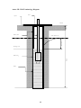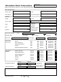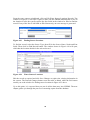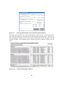
1
Somalia Water Sources Information Management System (SWIMS) Technical Report No. W-06 Vol. I – Field Data Collection August 2006 (Revised - July 2010) Somalia Water and Land Information Management Ngecha Road, Lake View. P.O Box 30470-00100, Nairobi, Kenya. Tel +254 020 4000300 - Fax +254 020 4000333, 1 http//www.faoswalim.org. Email: [email protected] Website: Funded by the European Union and implemented by the Food and Agriculture Organization of the United Nations Disclaimer The designations employed and the presentation of material in this information product do not imply the expression of any opinion whatsoever on the part of the Food and Agriculture Organization of the United Nations and the SWALIM Project concerning the legal status of any country, territory, city or area of its authorities, or concerning the delimitation of its frontiers or boundaries. This document should be cited as follows: Cody J. (2006), Somalia Water Sources Information Management System (SWIMS). Technical Report No W-06, Volume I–Field Data Collection, FAO-SWALIM, Nairobi, Kenya. i Table of Contents 1.0 1.1 1.2 2.0 INTRODUCTION TO SWIMS ..................................................................1 Description of SWIMS and its Components..................................................1 Purpose of this Manual ..................................................................................2 FIELD DATA COLLECTION...................................................................3 2.1 Water Characteristics .....................................................................................3 2.1.1 Electrical conductivity (EC) ......................................................................3 2.1.2 Hydrogen ion (pH).....................................................................................4 2.1.3 Colour ........................................................................................................4 2.1.4 Taste and Smell..........................................................................................5 2.2 Location Details .............................................................................................5 2.2.1 GPS handsets .............................................................................................5 2.2.2 Thuraya satellite phones ............................................................................6 2.2.3 Humanitarian Reference Grid (HRG) maps ..............................................6 2.3 Length and Height..........................................................................................7 3.0 STRUCTURE OF THE FIELD DATA FORMS......................................8 3.1 Completing the Field Data Forms..................................................................8 3.1.1 Data management.......................................................................................9 3.1.2 Location .....................................................................................................9 3.1.3 Function and use ......................................................................................10 3.1.4 Water characteristics................................................................................11 3.1.5 Supply and distribution ............................................................................11 3.1.6 Source management .................................................................................12 3.1.7 Physical parameters: Berkad....................................................................13 3.1.8 Physical parameters: Dam........................................................................14 3.1.9 Physical parameters: Borehole.................................................................15 3.1.10 Physical parameters: Dug well.................................................................17 3.1.11 Physical parameters: Spring.....................................................................18 3.1.12 Physical parameters: Other ......................................................................19 ANNEXES ..................................................................................................................20 Annex I: Glossary and Definitions...........................................................................21 Annex II: SWIMS Field Equipment List .................................................................24 Annex III: Well Terminology Diagram ....................................................................25 Annex IV: SWIMS Drop Down Fields .....................................................................26 Annex IV: SWIMS Field Data Collection Forms .....................................................28 ii 1.0 INTRODUCTION TO SWIMS The Somalia Water Sources Information Management System (SWIMS) was developed to provide a mechanism for constructing and maintaining an inventory of water sources in Somalia. It provides suitable planning level information for actors in the water sector in Somalia to support coordination, decision making and monitoring. In the design phases of SWIMS, the following objectives for the system were identified: 1. To provide a tool for non-GIS Specialists to manage and maintain spatial data and associated attributes on water sources. 2. To provide a tool to allow easy translation of data collected in the field to a centralised, national database. 3. To provide a tool that would assist users in managing water sources information in a systematic and standardised way. In designing a tool to meet these objectives, SWALIM produced an information management tool for water sources professionals in Somalia that includes; spatial data management capabilities; time-series management capabilities; past, current and future interventions information management; metadata management in accordance with ISO 19115; automated validation and verification of data; user management capabilities; and automated reporting functions. In addition, because SWIMS provides a means of reporting and managing spatial data, it is part of a national water sources Geographical Information System (GIS), which enables SWALIM and other users to produce and update maps at national, regional and district level. 1.1 Description of SWIMS and its Components In its broadest form SWIMS consists of: • Standard data collection methodologies to provide consistency across and between various data sets (standardized SWIMS data collection forms) • A software application to ensure that the data collected is stored correctly and consistently in the database (SWIMS data base application) • The personnel using the standard data collection and reporting formats. The data contained in the SWIMS standard formats is categorised as follows: • • • • • • Data Management Functioning and Use Physical Parameters Water Characteristics Supply and Distribution Source Management 1 The data can be further classified as quantitative and qualitative. This distinction is important in using SWIMS, in understanding the system set up, and in understanding the type of information that can be extracted from the system. For the purposes of this manual and SWIMS, we define quantitative data as data in numerical form that is collected in a replicable, objective way (e.g. GPS coordinates, EC and pH values, measurements of length, temperature, dates etc.). Qualitative data is defined as data, often non-numerical in form, which is collected in a way that may not be replicable and is subjective (e.g. number of users or livestock using a source, general condition of a source, smell, taste etc.). It should be noted that this definition of qualitative data also includes photographs, sketches, sound recordings, electronic files, all of which the SWIMS application can be used to manage. In many ways the definitions given above are an arbitrary distinction. To some extent all quantitative data is based upon qualitative judgments; and all qualitative data can be described and manipulated numerically. By using the SWIMS information sheets and software, multiple users can collect and manage water sources data in a systematic way. The SWIMS system is designed to restrict the type of descriptions of qualitative data that a user can employ so that the multiple data sets in the system will be comparable and facilitates these comparisons to be made in a systematic and replicable manner. Further, because SWIMS can maintain histories of both quantitative and qualitative data, it allows users to compare and monitor water sources on a temporal and spatial basis. 1.2 Purpose of this Manual The purpose of this field guide is to ensure a common approach to collecting data in the field is employed by all users of SWIMS. This is the critical first step to ensuring data quality and consistency both across and within the data sets housed in SWIMS. While the SWIMS information sheets can be used by non-technical staff as a means of monitoring water projects, it is recommended that the Physical Parameters and Water Characteristics sections should be completed by well trained technicians. This manual is primarily intended for use by the technicians within the water sector in Somalia as a reference for SWIMS data collection. The manual provides guidance on equipment, field monitoring techniques, and filling the SWIMS field data forms. The data forms provide a crucial link between fieldwork and the database, allowing for flexibility in data entry and a means of verification of the data that is entered on the database. 2 2.0 FIELD DATA COLLECTION SWIMS is a tool designed to build an inventory of water sources in Somalia that will allow a basic characterization of the sources in terms of physical, socio-economic and management practices. The attributes measured for SWIMS reflect an attempt to balance the water sources database information requirements with ease of deployment and reduced complexity. 2.1 Water Characteristics Samples taken from a body of water are representative of the water body only at the time and place of sampling. The sample should be taken directly from the source, not from delivery pipes or storage containers. The tests required on water characteristics for SWIMS have been chosen to provide a basic characterization of the water chemistry, and are not intended to be used to monitor water quality or enforce standards. Tests of water quality for the purposes of setting or enforcing regulatory standards should be carried out in a recognised professional laboratory. Such detailed analysis programmes are outside the scope of SWIMS, and hence this manual. However, where full chemical analysis is available for the water sources, such information can be integrated within SWIMS1. 2.1.1 Electrical conductivity (EC) Salts, acids and bases, when dissolved in water, conduct electricity owing to the motion of positive (cations) and negatively charged (anions) through the liquid. Liquids that conduct electricity in this way are called electrolytes. The specific current carrying ability of an electrolyte is called its electrical conductivity and has the units S m-1 (Siemens per metre), or micro Siemens per centimetre (μS cm-1), as used in SWIMS. The electrical conductivity is an indirect measure of the ions present in the water and depends on: 1. 2. 3. 4. the concentration of the ions present; the nature of the ions; the temperature of the solution; and the viscosity of the solution. Thus measurement of EC determines the concentration of dissolved ionic species in water. As EC varies with temperature, comparisons between EC measurements made at different temperatures are meaningless. It is imperative that all EC measurements be reported at the 25° Celcius reference temperature. Many of the modern EC meters however have an automatic temperature correction facility. The EC meters should be well calibrated according to the manufacturer’s instructions. If such reports are available electronically they can be managed within the SWIMS application using the Attach Files Wizard, which will file the documents using the date, location and metadata. 1 3 The procedure for measuring EC varies depending on the type of EC meter being used. It is recommended that the field technicians be familiar with the equipment before going to the field to avoid making wrong measurements. 2.1.2 Hydrogen ion (pH) pH is a measure of the activity of the hydrogen ion (H+) in water and is reported as the reciprocal of the logarithm of the hydrogen ion activity. The pH scale ranges from 0 to 14. 0 7 14 Acidic Neutral Basic Pure water has a neutral pH of 7; water with a pH < 7 is considered acidic, soft and corrosive; while water with a pH > 7 is considered basic and hard. The normal range for pH in surface water systems is 6.5 to 8.5 and for groundwater systems 6 to 8.5. For pH meters used with SWIMS, it is recommended that calibration be carried out as per the manufacturer’s instructions. Calibration is also required after the electrodes have been replaced, or if the electrodes have been stored and have been allowed to dry out. Periodic cleaning and inspection of the electrodes is also required, as contaminants at the electrode junctions can affect the measurements obtained. In general, the manufacturer’s instructions for storage care and maintenance for both the electrodes and the meter should be followed. As with the measurement of EC, the procedure for measuring pH varies depending on the type of pH meter being used, and the field enumerators should be familiar with the equipment to avoid mistakes. 2.1.3 Colour Within SWIMS, colour is regarded as a qualitative attribute due to the subjectivity to the interpretation of colour. The colour attribute is included because it is an important determinant of the acceptability of water for different purposes. Colour may also indicate the presence of dissolved or suspended substances in the water. For example blue-green colour can indicate the presence of algae, the presence of which can cause the formation of organochlorines when chlorine is used as a disinfectant, making the treated water unpalatable. Similarly, a reddish/brown colour may indicate the presence of iron and manganese. The general procedure for testing and reporting colour in SWIMS is as follows: (i) (ii) (iii) (iv) Fill a clear, clean glass jar or test tube with water from the source; Standing with your back to the sun, hold the jar with water sample at eye level with outstretched arm. Allow sample to settle for about 60 seconds to allow trapped air, which may impart cloudy appearance to water, to clear. Hold a sheet of clean, white paper or card behind the sample and note colour. 4 2.1.4 Taste and Smell Within SWIMS, taste and smell are also regarded as qualitative attributes. These attributes are included because they are important determinants of the acceptability of water for different purposes. For example, taste and smell can indicate the presence of contaminants in water, creating the necessity for further investigations to determine the level of contaminant concentration. 2.2 Location Details The location details of water sources are highly ranked in SWIMS, as all other parameters are attached to the location. The water source location is described in terms of administrative units (region, district, village/settlement), as well as the X-Y coordinates which are crucial for mapping the water sources. The coordinates of a water source can be obtained through the following: 2.2.1 GPS handsets The Global Positioning System (GPS) consists of 24 satellites orbiting the earth at about 19 000 km. These satellites emit a low powered radio signal which is received by GPS receivers on the line of sight. The GPS receiver receives two types of information on these radio waves; • Almanac data which lets the receiver know the approximate position of the satellites and is valid for about 6 hours. • Ephemeris data which is constantly updated and contains corrections to the almanac data. GPS operates on a time of arrival basis. Put simply this means that the velocity (VS) of the received signal is multiplied by the travel time (T) to give the distance (D) from a satellite to the receiver VS ×T = D The GPS receiver calculates it’s position on the earths surface by carrying out this calculation for all the satellites in it’s line of sight and triangulating the distance form each. Three satellites allow the GPS to calculate its two-dimensional position (Latitude and Longitude). Four satellites allow the GPS to calculate its three-dimensional position (Latitude, Longitude and Altitude). When using a GPS handset to collect data for SWIMS, the following settings should be ensured: Time Zone: GMT + 3.00 Units: Metric Datumn: WGS 84 North Reference: True Position Format: Decimal 5 The GPS coordinates should be collected as waypoints, and saved in the GPS handset as well as recorded on the field data forms. 2.2.2 Thuraya satellite phones Thuraya satellite phones can provide GPS co-ordinates in decimal degree format to an accuracy of less than 100m. The datum used is WGS 84. The procedure for obtaining the coordinates using the Thuraya phone is outlined below: (i) Go To "Menu" (ii) Select "GPS Manager" (iii) Select "Current Position" (iv) Upon reading the GPS Coordinates, press "Options" (v) Select "Save" (vi) Select an empty location from the list, Press "select" (vii) Enter a new name for your point (viii) Press "Save" Just like the GPS handsets, satellite phones only operate outdoors, and away from buildings, trees and other obstacles. 2.2.3 Humanitarian Reference Grid (HRG) maps Humanitarian Reference Grid (HRG) maps have been adopted by the organizations working in Somalia to locate positions in situations where the use of GPS is not possible. The grid divides Somali into 404 rectangular blocks (like the one shown in the figure below), each corresponding to the internationally recognized topographic map file. 6 The rectangular blocks are given a unique alpha-numeric reference number e.g. NA38-067. Each of these rectangles is then sub-divided in to 88 square cells: 11 across and 8 down. Each square cell is approximately 5 km by 5 km, representing an area of 25 km2. The square cells are referenced from A to K horizontally and from 1 to 8 vertically. To report the position of a water source: - Locate the square cell on the map where the source lays, using estimated distance and direction from a known point such as a clinic, school or settlements as a guide. - Note the alpha-numeric rectangle code (e.g. NA-38-067) - Note the numeric reference of the square cell where the source is located (e.g 2) - Note the alphabetic reference of the square cell where the source is located (e.g D) - Report the location for the water source by quoting the full grid reference as follows: alpha-numeric rectangle code – cell numeric reference – cell alphabetic reference (i.e NA-38-067-2D). 2.3 Length and Height SWIMS requires that a number of distance parameters be reported. In general these are; • Length/ Radius. • Width • Depth/Height In addition, the following parameters, derived from length measurements are also required; • Area • Volume All distance measurements for SWIMS should be done in metric units. It is important that a local datum be clearly established for depth/height measurements. This local datum should be marked on the source with an X, either with red paint or by inscription. The position of the datum should be clearly identified on a sketch of the water source, and if possible, on a digital photograph. Note also that in SWIMS the local coordinate2 system used has the positive z-axis pointing directly downwards towards the centre of the earth. In establishing a datum it is best if a permanent point at or close to ground level is chosen so that all depth measurements are reported using positive numbers, and all elevation or height measurements are made using a negative value. This should not be confused with the Global Coordinate System used for the GPS. This uses the Global Datum of WGS 84, so elevations above sea level on the GPS are reported as a positive number. 2 7 3.0 STRUCTURE OF THE FIELD DATA FORMS The SWIMS field data collection forms are divided into six categories based on the common water source types in Somalia: boreholes, dug wells, dams, springs, berkads and others. In each of these categories, the parameters monitored have been categorised into detailed and essential information. In the previous versions, data collection forms for the detailed and essential information were separate, but in the current version the two forms have been merged into one. In the merged data forms, the fields considered essential are marked bold to differentiate them from the rest of the parameters. The essential information contains a limited number of fields detailed information. It represents the minimum data required source in the database and maintain the integrity of the records. minimum information required to complete the inventory of Somalia. extracted from the to include a point This represents the water sources for The detailed information represent the data required to carry out the characterisation and analysis functions of the data base. It includes information on various categories that will allow statistical and spatial analysis in terms of socio-economic parameters, water quality, operation and management of the water sources. The attributes on the SWIMS data forms are broken down into a series of categories/headings, listed in Section 1.1. All of these categories except the Physical Parameters are exactly the same. The approach used in the manual is to describe the common sections first, and then to discuss the Physical Parameters under a series of sub-headings relating to each source type. 3.1 Completing the Field Data Forms In general, when in the field, black/blue ink should be used to complete the information sheets so as to ensure the quality and legibility of photocopies and scans. Ball point pens should be used in preference to fountain pens or felt-tip pens so as to prevent smearing and running. Ball-point ink is also more resistant to water. The fields should be completed carefully in neat, legible block capitals as the attribute is measured. Making a fair copy from field notes is not recommended due to the possibility of error when copying to the sheets. When filling in the ‘check-boxes’ the 9 symbol should be used. If a check box is ticked with the 9 symbol by mistake, this symbol should be converted to an 8 symbol. In this case the 4 points of the 8 should extend outside the check box. In general, the SWIMS data collection forms have been designed to provide as complete an inventory as possible under the prevailing circumstances in Somalia. It is recognised that in many circumstances it will not be possible for the enumerator to complete the detailed information sheets in their entirety. If the information is not available, the field should be left blank. Where a field on the forms is left blank, it will be assumed that this indicates a ‘don’t know’ answer. This is similar to the procedure adopted in the SWIMS application, where a ‘Null’ value in a database field is assumed to indicate a ‘don’t know’. 8 In reading the descriptions in the following sections note that where the term ‘precision’ is used it is used in the information technology context and is not meant as to represent the resolution to which a measurement is reported. 3.1.1 Data management The data management section of the sheets is critical in maintaining the data integrity of SWIMS datasets. It contains 5 fields in the header section of the form. • Metadata Reference: a unique reference to a metadata record. • Date: the date the location was visited and the form filled in. • Inspected By: the name of the person who physically collected the data. • Entry Agency: the name of the agency who entered the data on the SWIMS software • Inspecting Agency: the name of the agency responsible for physically collecting the data 3.1.2 • • • • • • • • • • • • Location Region: the administrative region that the source is in. District: the administrative district that the source is in. Source Name: the local name for the source / where the source is located. Where there are a number of sources with the same name in an area, then each individual source should be given a numeral label (e.g. SOURCE1, SOURCE2). North: the latitude (x) coordinate of the source, reported to a precision of 6 decimal places. East: the longitude (y) coordinate of the source, reported to a precision of 6 decimal places. GPS Make and Model: the make and model of the equipment used to establish position coordinates. If humanitarian reference grid maps are used, the map reference should be reported here. Positional Accuracy3: the positional accuracy indicated by the GPS, reported to a maximum precision of 1m. Elevation: the elevation of the source in meters above sea level, reported to a maximum precision of 1m. Nearest Settlement Name: the name of permanent settlement nearest to the water source. Nearest Settlement Distance: the distance in km, reported to a maximum precision of 100 m (0.1 km) to the nearest permanent settlement, as indicated by the odometer on a car or motor bike4. Users: describe the predominant users of the source as rural, urban or nomadic, or all three. Municipal Code: a description of the location for the sources. Because a GPS can give different accuracies depending on it’s type (recreational, surveying etc), this attribute will be used in determining which GPS coordinates to use in the national database in the case where there are discrepancies in reported coordinates. In such cases, the coordinates with the lowest value of Positional Accuracy will be used. 3 Where the source is located within the boundaries of the Settlement, this field should be completed with a ‘zero’. If the field is left blank a ‘don’t know’ answer will be assumed. 4 9 3.1.3 • • • • • • • • • • • • • 1 Function and use Functioning: the current operational status of the water source (if abandoned an explanatory note should be included in the notes box to the right of the functioning question. Operator: does the water source have a trained, permanent operator? Permanent Use: is the water source used throughout the year? Humans; Sheep/Goats; Camel; Cattle; Irrigated Area: this section is included so an estimate of the user numbers can be provided. These fields represent qualitative estimates of the number of users for any given season. It is recognised that estimates will vary in time due to population movements, climate variables and other factors. Estimates will also vary depending on who collected the data and how the estimates were conducted. In general, as many of the sources user’s as possible should be questioned and the enumerator’s best judgement should be used to provide indicative figures for users under each of the categories. Distance to Nearest Permanent Source: SWIMS defines a permanent source as a water source such as a borehole, spring, dam or stream that, in a normal year, provides water at all times throughout the year. Description of Nearest Permanent Source: a description of the nearest permanent source. GPS coordinates should be included if possible in the notes section. Number of Other Water Sources in the Area: this is, to a large extent, an example of qualitative data given the subjectivity inherent in defining the term ‘Area’. As a general rule of thumb, SWIMS defines the Area in question as all other water sources that are within one days return walk of the water source. Settlements Served by the Source: a common definition of settlements served poses some difficulties, both in terms of time and distance. Similarly to the user estimates, the more of the users questioned the better. If there is an operator or a management committee they should be questioned, especially if water trucking is practised. General Condition: the enumerator’s opinion of the general condition of the source as good, fair or poor. Sanitary Condition: the enumerator’s opinion of the sanitary condition of the source as good, fair or poor. Environmental Condition: the enumerator’s opinion of the environmental condition of the source as good, fair or poor. Intervention Required: the enumerator’s opinion of type intervention required on the source as develop, improve or rehabilitate (if none required leave unchecked). Last Intervention: the name of the agency, if any, which carried out a physical intervention at the source, and the date (mmyyyy format) of the intervention. (a general description of the intervention should be included in the notes box if possible). Source Established: the name of the agency that established the source, and the date (mmyyyy format) that the source was established. (if the source was established by a community or individual, please indicate). 10 3.1.4 • • • • • • • • • • • • • Water characteristics EC @ 25° C: the electrical conductivity of a sample from the source, corrected to the reference standard of 25° Celsius. EC Meter Make and Model: the name of the manufacturer of the EC meter and the manufacturer’s model number. Calibration Date: the date that the EC meter was last calibrated. pH: the pH of a sample from the source reported to a maximum precision of 0.1. pH Meter Make and Model: the name of the manufacturer of the pH meter and the manufacturer’s model number. Calibration Date: the date that the pH meter was last calibrated. Temperature: the temperature, reported to a maximum precision of 0.5° Celsius, at which the pH measurement was made. Turbidity: if available, reported in NTU. E.Coli: if available, reported in MPN. Colour: the colour of a water sample from the source Smell: the smell of a water sample from the source Taste: the taste of a water sample from the source Full Chemical Analysis Available: analysis such as major ion chemistry, bacteriological screens etc. 3.1.5 Supply and distribution • • • • • • • • • • Supply System Condition: the condition of a distribution network, including animal troughs, if applicable. Engine Room Condition: the condition of the engine room, if applicable Storage Tank Condition: the condition of a storage tank, including valves and connections, if applicable. Storage Tank Capacity: the usable volume, i.e. the volume calculated between the tank outlet and tank overflow, for the storage tank in cubic meters, reported to a maximum precision of 1 litre (0.001 m3) Pipeline Delivery Length: the complete length of the main delivery pipeline in metres, including branches, reported to a precision of 1m Taps / Outlets: the number of user outlets attached to the source distribution system, if applicable. If none enter ‘0’. Kiosks: the number of public vending points associated with the source, if applicable. If none enter ‘0’. Animal Troughs: the number of animal watering troughs associated with the source and it’s distribution system, if applicable. If none enter ‘0’. Tankering Points: the number of points associated with the source and it’s distribution system where water is drawn for distribution by tanker (mechanical or animal traction). If none enter ‘0’. Water Lifting Technology: indicate the type of water lifting technology at the source (multiple choices are valid) 11 • • • • • • • • • • • • • • • • • 3.1.6 • • • Pump Make5: the name of the pump manufacturer Pump Model6: the pump manufacturers model number Pump Serial Number: the pump manufacturer’s serial number. Date Installed: the date, in mmyyyy format, that the pump was installed. Delivery: the flow rate, reported to a precision of 1 ls-1 (0.001m3/s), of the pump. Head: the delivery head of the pump, reported to a precision of 100 mm (0.1 m), at which the flow rate is achieved. Prime Mover: indicate the type of power source at the source (multiple choices are valid). Engine Make: the name of the generator manufacturer. Engine Model: the engine manufacturer’s model number. Engine Serial: the engine manufacturer’s serial number. Date Installed: the date, in mmyyyy format, that the engine was installed. Engine Output7: the engine output, reported to a precision of 1 Watt. Generator Make: the name of the generator manufacturer. Generator Model: the generator manufacturer’s model number. Generator Serial Number: the generator manufacturer’s serial number. Date Installed: the date, in mmyyyy format, that the generator was installed. Generator Output: the generator output, reported to a precision of 100 Voltampere (0.1kVA) of the generator. Source management Owner: indicate whether the source is privately owned, community owned or other. Water Selling Price: the cost of water per specified unit(s) in dollars. Management Committee: indicate whether the source is managed by a management committee or not. Many pump, engine and generator manufacturers provide electronic versions of their technical literature available via the World Wide Web. The Add Files Wizard within the SWIMS application can be used to attach this documentation, if available to a specific source. 5 6 Pump, engine and generator manufacturers place this information on metal plates that are riveted to the housing/bodies of their assemblies. This plate should be checked each time the source is visited. It is particularly important to check the serial number of equipment at each visit. 7 If the engine has been de-rated, this details should be included in the Notes box in Function and Use Section. 12 3.1.7 • • • • • • • • • • • Physical parameters: Berkad No. of Berkad in Cluster: indicate the number of berkads available in the same cluster with the source (berkad). Catchment area: an estimate of the catchment area, reported to a precision of 1 m2, of the berkad. Reservoir Capacity: the usable volume of the berkad, reported to a maximum precision of 1 m3. Reservoir Dimensions, Depth: the vertical distance, reported to a maximum precision of 100 mm, (0.1m) from the chosen datum to the deepest part of the reservoir. Reservoir Dimensions, Length/Radius: the length, reported to a maximum precision of 100 mm (0.1m), of the reservoirs first dimension (if prismatic) or radius (if spherical) Reservoir Dimensions; Width: the length, reported to a maximum precision of 100 mm (0.1m), of the reservoirs shortest or second dimension (if prismatic). Silt Trap: does the Berkad have a functional silt trap? Roof: is the surface area of the Berkad covered? Supply Chamber: does the Berkad construction include a separate chamber from which water is drawn? Filter: does the berkad have a water filter? Fencing: is access to the Berkad restricted around it’s entire perimeter? 13 3.1.8 • • • • • • • • • • • • • • Physical parameters: Dam Type of Dam: choose a description for the type of dam. Number of Dams in Cluster: The number of dams in a single cluster. Silt Trap: does the Dam have a functional silt trap? Reservoir Capacity: the usable volume, reported to a maximum precision of 1 m3 of the reservoir. Reservoir Dimensions, Depth: the average vertical distance, reported to a maximum precision of 1m from the chosen datum to the deepest part of the reservoir Reservoir Dimensions, Length/Radius: the length, reported to a maximum precision of 1m, of the reservoirs first dimension (if prismatic) or radius (if spheroid) Reservoir Dimensions; Width: the length, reported to a maximum precision of 1m, of the reservoirs shortest or second dimension (if prismatic). Bund Wall Height; the vertical distance, reported to a maximum precision of 1m from the chosen datum to the deepest part of the reservoir (use negative number if above datum) Bund Wall Material; choose a description of the main material used in the dams construction. Catchment Area; an estimate of the catchment area of the dam, reported to a maximum precision of 1m2. Spillway: does the Dam construction incorporate a functional spillway? In-flow channel: is there an inflow channel connected to the dam? Fencing: is access to the Dam restricted around it’s entire perimeter? Well: does the dam have a well associated with it? 14 3.1.9 • • • • • • • • • • • • • • • • • • • • • • • Physical parameters: Borehole Type of Well: choose a description for the borehole type. No. of Wells in Cluster: the number of boreholes in a single cluster. Depth: the vertical distance, reported to a maximum precision of 100mm (0.1 m), from the chosen datum to the bottom of the well shaft. Static Water Level: the vertical distance, reported to a maximum precision of 100mm (0.1 m), from the chosen datum to the potentiometric surface of the aquifer. Pump Test Type: the type of pump test that was carried out on the well Pump Test Source: please write the name/address/e-mail address where the pump test data is available, if known.8 Tested Max. Yield: yield from the well, reported to a maximum precision of 0.1m3 hr-1 as determined by the pump test Tested Max Drawdown: the maximum vertical distance, reported to a maximum precision of 100mm (0.1 m), from the chosen datum to the water level in the well shaft developed during the pump test. Recovery Time: the time that was recorded in the well test. This should be rounded to the nearest 30 minutes (½ hour). Specific Capacity: the quantity of water that a borehole can produce per unit of drawdown, reported to a maximum precision of 0.1m3 hr-1 m-1. Operating Yield: the extraction rate from the well, reported to a maximum precision of 0.1m3 hr-1 under normal operating conditions. Operating Drawdown: the vertical distance, reported to a maximum precision of 100mm (0.1 m), from the chosen datum to the water level in the shaft under normal operating conditions. Operating Hours: the number of hours the well is operated in a day, rounded to the nearest 30 minutes (½ hour). Pump Casing Type: what material is the pump casing constructed from? Pump Casing Size: the internal bore of the pump casing, reported to a maximum precision of 1mm. Riser Type: what material is the riser constructed from? Riser Size: the internal bore, reported to a maximum precision of 1mm, of the riser. Cut Off Electrode: is there a functioning cut-off electrode on the system? Screen Depth: the vertical distance, reported to a maximum precision of 100 mm (0.1 m), from the chosen datum to the start of the screen section; & the vertical distance, reported to a precision of 1 mm (0.1 m), from the chosen datum to the end of a screen section. Screen Type: the screen construction and material. Well Head Protected: does the well have a sanitary seal? Pump level: the vertical distance, reported to a maximum precision of 100mm (0.1 m), from the chosen datum to the water pump. Hydraulic Conductivity: the ease with which water can move through pore spaces or fractures of a soil. Note that if the pump test documentation is available it can be scanned and stored within the SWIMS application using the Attach Files Wizard. 8 15 • • • • Transmissivity: the rate at which a water of a prevailing density and viscosity is transmitted through a unit width of an aquifer or confining bed under a unit hydraulic gradient. Piezometric Level: the vertical distance, reported to a maximum precision of 100mm (0.1 m), from the datum to the level of water in the aquifer. Lithology Known: is the lithology of the aquifer for the source known from geophysical logs etc. Lithology Source: provide contact details for the source of Lithological data if available. 16 3.1.10 Physical parameters: Dug well • • • • • • • • • • • • • • • • • • Type of Dug Well: please choose a description for the type of dug well No. of Wells in Cluster: the number of dug wells in a single cluster. Depth: the vertical distance, reported to a maximum precision of 1mm (0.001 m), from the chosen datum to the bottom of the well shaft. Static Water Level: the vertical distance, reported to a maximum precision of 100mm (0.1 m), from the chosen datum to the potentiometric surface of the aquifer. Lining Material: what type of material is the well lining made of? Shaft Diameter: what is the diameter of the well shaft? Apron: does the well have an apron? Soakaway: does waste water from the well drain into a soak away pit? Infiltration Gallery: does the well have an infiltration gallery? Pump Test: has the well been pump tested? Tested Yield: what is the maximum volumetric flow rate, reported to a maximum precision of 0.1 m3 hr-1, achieved during the pump test? Operating Yield: what is the extraction rate from the well, reported to a maximum precision of 0.1 m3 hr-1, under normal operating conditions? Operating Drawdown: the vertical distance, reported to a maximum precision of 100 mm (0.1 m), from the chosen datum to the water level in the shaft under normal operating conditions? Operating Hours: for how many hours a day is the well operated, rounded to the nearest 30 minutes (½ hour). Recharge Rate: describe the rate, as either good, fair or poor, at which the water level in the well returns to the static water level after normal operational extraction. Pump Level: the vertical distance, reported to a maximum precision of 100mm (0.1 m), from the chosen datum to the water pump. Riser Size: the internal bore, reported to a maximum precision of 1mm, of the riser. Well Head Protected: does the well have a sanitary seal? 17 3.1.11 Physical parameters: Spring • • • • • • • Type of Spring: the hydrogeological classification of the spring No. of Discharge Points: how many distinct ‘eyes’ does the spring have? Cumulative Discharge Rate: the total volumetric flow rate, reported to a maximum precision of 0.1 l s-1 of the spring Seasonal Deviation in Discharge: the magnitude of fluctuation in the volumetric flow rate of the spring between wet and dry seasons. Rate Test Type: a description of the type of rate test carried out. Rate Test Source: provide contact details for the source of rate test data if available. Source Protected: has the source been protected from contamination? 18 3.1.12 Physical parameters: Other • • • • • • • • • • • • Type of Source: provide a description of the source type. Water Category: classification of the primary source of the water. Source Capacity: an estimate of the volume of water, reported to a maximum precision of 100 l (0.1 m3), of the sources usable storage capacity. Source Yield: the yield of the source, reported to a precision of 1 l s-1 (0.001 m3s-1) Source Dimensions, Depth: the vertical distance, reported to a maximum precision of 100 mm, (0.1m) from the chosen datum to the deepest part of the reservoir Source Dimensions, Length/Radius: the length, reported to a maximum precision of 100mm (0.1m), of the reservoirs first dimension (if prismatic) or radius (if spherical) Source Dimensions; Width: the length, reported to a maximum precision of 100mm (0.1m), of the reservoirs shortest or second dimension (if prismatic). Aquifer: a subsurface zone of porous rock, unconsolidated gravel, fractured rock or cavernous limestone, that yields economically important amounts of water to wells. Watershed: the area contributing to flow into the water source. Tugga: seasonal stream connected to the source Source Protected: has the source been protected from contamination? Pump Level: the vertical distance, reported to a maximum precision of 100mm (0.1 m), from the chosen datum to the water pump. 19 ANNEXES 20 Annex I: Glossary and Definitions Aquifuge An absolutely impermeable lithologic layer that will not transmit any water. Aquitard (A.k.a. Aquiclude) a lithologic layer of low permeability that is incapable of storing or transmitting groundwater in sufficient quantities for exploitation. Aquitards may be important on a large scale by virtue of their area. Catchment area The area that can supply water to a point (generally the inlet of a source is SWIMS) under the action of drainage by gravity. Confined Aquifer (A.k.a. Artesian) an aquifer that is overlain by a confining layer that allows recharge in an area where the aquifer outcrops or from downward percolation of water through the confining layer. Contact spring A spring formed at a lithologic contact where a more permeable layer overlies a less permeable layer Datum A known and constant surface relative to which position measurements are made. Depression spring A spring formed when the water table reaches a land surface because of a change in topography Develop Enumerator advises that a new source is required e.g due to permanent expansion of population) or an alternative source is required (e.g. due to salinity problems in the water or other user concerns) Drawdown The reduction in the Static Water Level within the well resulting from abstraction. Embankment dam An impermeable obstruction in a river channel or narrow valley constructed for the purpose of impounding water in the channel or valley upstream of the dam. Environmental Condition The Enumerator’s assessment of the area the area surrounding the water source. For example are there latrines within a 20m radius of the source? Is the area well drained? Is the source freely accessible to all users? Fault Spring A spring formed by the movement of two rock units on a fault General Condition The Enumerator’s assessment of the general operation and structural condition of the source. Are all masonry or concrete elements sound? Is the pump working efficiently? Are fences well maintained? Improve Enumerator advises that improvements to the source are required (e.g. capping an open spring, installing a pump on an open well, erecting a roof over a berkad etc.) Infiltration gallery An infiltration gallery comprises a trench backfilled with gravel media, in which is placed a slotted, drilled, open jointed pipe or purpose made well screen, for the purpose of supplying water 21 filtered to a collector well from a surface source. May be constructed on the bank or in the bed. Infiltration well Joint/Fracture spring A point source well constructed in the stream/river bed using a porous ring that collects filtered surface water through infiltration through the stream bed. The top ring is normally extended above the flood level or sealed (see Infiltration Gallery) A spring formed by fracture or jointing of an individual rock unit. Owner Indicate whether the source is privately owned, community owned or other. Other could include a well in a hospital or a school which, while not open to the community at large, is still a public amenity. Perched Aquifer A layer of saturated soil or sediment formed by a lens of low permeability formed in more permeable materials. Potentiometric Level (A.k.a. Piezometric level:) the level of an imaginary surface in m to which the water level rises. In a confined aquifer it is the height to which the water would rise by virtue of the pressure in the aquifer. (see also standing water level). Well Casing (A.k.a. Casing, pump casing): a tube used as a permanent lining for the well shaft. Rehabilitate Enumerator advises that restoring the source to it’s previous condition is required (e.g. replacing a pump or generator in a drilled well, repairing a damaged storage tank etc.) Riser A pipe carrying water from within a well to a point of discharge Riverside well A well dug adjacent to a surface water source that collects filtered surface water through infiltration through permeable banks. Sand dam A dam, built up over several years, built by accumulating sediments by means of an obstruction across a Tugga. Sand storage dam A retaining wall constructed to accumulate sediment so as to retain and store water in those sediments. Normally found in Tuggas Sanitary Condition The Enumerator’s assessment of the sanitary condition of the source. Does the source have a sanitary seal? Is the source protected from contamination from surface run-off and seepage? Does the source have adequate drainage? Is the water lifting method employed at the source sanitary? If the source is used to water animals, are troughs provided? Semi-confined Aquifer: (a.k.a) A confined aquifer that is bounded above or below by an aquitard. Silt-trap A low level obstruction in an inlet channel constructed so as to restrict water velocity, allowing silt to settle from the water and desilted water to enter a reservoir by overflowing the obstruction. Sinkhole spring A spring created by groundwater flowing from a sinkhole in a karstic terrain 22 Soak-away An excavation with a stable, porous lining with it’s upper edge sealed constructed so as to receive wastewater and allow it to drain away through the sides of the excavation. May be backfilled with stones to support the roof and sides. Specific capacity The rate of discharge of water from a well per unit of drawdown Static Water Level (a.k.a Specific Head) the height, relative to an arbitrary datum, of a column of water that can be supported by the static pressure in the well. Sub-surface dam A dam constructed below ground level that prevents the passage of groundwater in the sand bed of a Tugga. Un-confined Aquifer: (A.k.a. Water table aquifer) an aquifer that is overlain by continuous layers of high intrinsic permeability materials that allow recharge through downward seepage through the unsaturated zone. Recharge can also occur through ground water movement or upward seepage. Usable volume The volume of water between the highest point on a reservoir and the lowest point on a reservoir that can supply water (e.g. the distance between reservoir overflow and reservoir supply ouflow) Yield The rate at which water is pumped from the source. 23 Annex II: SWIMS Field Equipment List pH, EC multimeter; with automatic temperature correction to 250 Celsius. Deep meter; length 250 – 450m Measuring tape; length 100m Manilla rope; 250m Sinking weight GPS handset / Humanitarian Reference Grid maps Digital camera Maps of survey areas Plastic beaker; capacity of 1 litre Stationery: plastic folders, clipboards, ball point pens, permanent markers, data collection forms First aid kit 24 Annex III: Well Terminology Diagram Apron Riser Datum z Sanitary Seal Drawdown Static Water Level Pumping Level Depth Well Casing Screen 25 Annex IV: SWIMS Drop Down Fields Location Borehole Physical Parameters Dam Physical Parameters Berkad Balli/War Driven/Tube Dam Sub-surface Jetted Well Drilled Well Dam Type Sand Dam Borehole Type Borewell Source Type Dug Well Check Dam Rotary Spring Embankment dam Percussion Earth Step-Drawdown Concrete Constant Discharge Masonry, brick Constant Discharge & recovery Other Don’t Know Material IDP Camp Municpal Code Pump test type Constant Drawdown Masonry, stone Large Pop. Centre (>10,000) Constant Drawdown & recovery Medium Pop. Centre( <10,000) Spring Slug/Bailer test Small Pop. Centre (<1,000) Don’t know Nomadic Settlement Don’t know Depression Rural Blank SpringType Contact Slotted Pipe Fault Screen type Bridge Slot Sinkhole Continuous Slot Joint/Fracture Louvred Bucket and stop watch Rate test type Don’t know Wier PVC Other PE Riser type ABS Stainless Steel Galvanised Steel 26 Water characteristics Dug Well Physical Parameters Aquifer Pungent/Alkaline Confined Hand Dug Pungent/Acidic Unconfined Collector Chlroine Perched Faecal/Nauseating Don’t know Dug well Type Riverside Aquifer Smell Infiltration Other Aquifuge None Concrete Aquitard/Aquiclude Confining State Steel Fresh None Masonry Brakish Don’t Know Lining Material Wood Taste Saline Other None Cloudy/Milky Other Physical Parameters Red/Brown River Colour Blue/Green Tugga Source Type Clear Canal Other Roof catchment None Ground catchment Surface Subsurface Water Type Run-off Mixed 27 Annex V: SWIMS Field Data Collection Forms 28 Metadata reference Detailed Information Sheet: Borehole Definition: A well developed by mechanical means. Typically drilled, with limited bore diameter and of significant depth. May also be called, drilled well, tubewell. etc. Data Management Date Inspected by Entry Agency Inspecting Agency Location Region District Source name GPS Make and Model North ° Positional accuracy East ° Distance to nearest settlement masl Nearest settlement name Elevation Users Urban Rural ± m km Municipal Code Nomadic Function and Use Functioning Yes No Abandoned Operator Yes No Don’t Know Yes No Don’t Know Permanent Use Notes: general condition, repairs required etc. Humans Gu Number Hagaa Number Deyr Number Jilaal Number Sheep/goats Gu Number Hagaa Number Deyr Number Jilaal Number Camel Gu Number Hagaa Number Deyr Number Jilaal Number Cattle Gu Number Hagaa Number Deyr Number Jilaal Number Irrigated area Gu ha Hagaa Distance to nearest permanent source Description of nearest permanent source km e.g. name, coordinates, source type, etc. Number of other Water Sources in the Area Berkad Number Dam Dug Well ha Deyr ha Jilaal ha General condition Good Fair Poor Sanitary Condition Good Fair Poor Environmental condition Good Fair Poor Borehole Number Number Spring Number Number Other Number Last intervention? Agency Number of settlements served by source? Number Source Established? Agency Intervention required? Develop Improve Rehab Date Date None Physical parameters No. of wells in cluster Type of well Depth m Pump test type Static Water Level (SWL) m3/hr Test max drawdown Recovery time hr Specific capacity Operating hours hr Operating Yield Operating drawdown m Pump casing type Pump casing size mm Riser type Riser size mm Cut-off electrode? Well-head Protected ? m Pump test source Test max. yield Screen depth: Ground level to SWL From m To Yes m m3/hr/m m3/hr No Yes Screen type Pump level No m Ground level to the pump inlet m If possible a sketch of the well design should be included in the space provided showing positions of pump housing, riser (production casing), blind and open screens. Hydraulic conductivity m/d m Piezometric Level Lithology known? m2/d Transmissivity No Yes Lithology source Water Characteristic EC @ 25°C ± µS/cm pH Temperature °C E.Coli MPN/100ml Make and model Calibration date pH meter Make and model Calibration date Turbidity Colour Taste Smell Additional chemical analysis available? EC meter Yes No Analysis source NTU Supply & distribution Supply system condition? None Good Fair Poor Engine Room condition? None Good Fair Poor Storage tank capacity m3 Taps/outlets Number Animal troughs Number Water lifting technology Storage tank condition? None Poor m Number Number Tankering points Surface Fair Pipeline delivery length Kiosks Submersible Good Mono Handpump Bucket & Windlass Rated Delivery Pump Model Number Make Prime Mover Petrol Serial Number Diesel Electric Delivery Date installed m3/s Solar panel Make Model Number Serial Number Date installed Engine output Generator Make Model Number Serial Number Date installed Generator output Owner? m Wind turbine Engine Source Management Head W kVA Cost per unit Private Management Committee? Additional notes & Sketches Yes Community No Tanker $/m3 Camel $/100 Jerican $/l Cattle $/100 Drum $/l Sheep/goat $/100 Other Metadata reference Detailed Information Sheet: Dug Well 1.1 Definition: Any source that taps groundwater that has been developed by non-mechanical means. The descriptor name may therefore be in Somali (eg. Beeyo, buq, laas, ceel) or English (eg. Collector well, hand dug well, traditional well, farm well, etc.). Data Management Date Inspected by Entry Agency Inspecting Agency Location Region District Source name GPS Make and Model North ° Positional accuracy East ° Distance to nearest settlement masl Nearest settlement name Elevation Users Rural Urban Nomadic ± m km Municipal Code Function and Use Functioning Yes No Abandoned Operator Yes No Don’t Know Yes No Don’t Know Permanent Use Notes: general condition, repairs required etc. Humans Gu Number Hagaa Number Deyr Number Jilaal Number Sheep/goats Gu Number Hagaa Number Deyr Number Jilaal Number Camel Gu Number Hagaa Number Deyr Number Jilaal Number Cattle Gu Number Hagaa Number Deyr Number Jilaal Number Irrigated area Gu ha Hagaa Distance to the nearest permanent source Description of nearest permanent source km e.g. name, coordinates, source type, etc. Number of other Water Sources in the Area Berkad Number Dam Dug Well ha Deyr ha Jilaal ha General condition Good Fair Poor Sanitary Condition Good Fair Poor Environmental condition Good Fair Poor Borehole Number Number Spring Number Number Other Number Last intervention? Agency Number of settlements served by source? Number Source Established? Agency Intervention required? Develop Improve Rehab Date Date None Physical parameters Type of dug well Depth m Yes Static Water Level (SWL) Ground level to SWL m m Operating yield No m3/hr Tested yield Operating drawdown Pump level Number Shaft diameter Lining Material Pump test No. of dug wells in cluster m Ground level to the pump inlet m3/hr Operating hours hr Riser size mm m Well-head protected ? Yes No Apron Yes No Soak away Yes No Soak away dimensions Depth Infiltration gallery Yes No Infiltration gallery dimensions Depth Recharge rate Apron dimensions Good Fair Length/Radius m m m Poor Width Length/Radius Width Length/Radius Width m m m m m Water Characteristic EC @ 25°C ± µS/cm pH Temperature °C E.Coli MPN/100ml EC meter Make and model Calibration date pH meter Make and model Calibration date Turbidity NTU Colour Taste Smell Additional chemical analysis available? Analysis source No Yes Supply & distribution Supply system condition? Engine Room condition? None Good Fair Poor None Good Fair Poor Storage tank capacity m3 Taps/outlets Number Animal troughs Number Storage tank condition? None Pipeline delivery length Kiosks Tankering points Good Fair Poor m Number Number Supply & distribution continued Water lifting technology Submersible Surface Mono Handpump Bucket & Windlass Rated Delivery Pump Make Prime Mover Model Number Petrol Serial Number Diesel Electric Delivery Date installed m3/s Solar panel Make Model Number Serial Number Date installed Engine output Generator Make Model Number Serial Number Date installed Generator output W kVA Cost per unit Tanker Owner? m Wind turbine Engine Source Management Head Private Management Committee? Additional notes & Sketches Yes Community No $/m3 Camel $/100 Jerrican $/l Cattle $/100 Drum $/l Sheep/goat $/100 Other Metadata reference Detailed Information Sheet: Dam A dam acts as a barrier to impound water. The most typical dams are Balli or War type, open ponds with a bund wall to impound surface runoff. Sub-surface and sand dams are also encountered. Data Management Date Inspected by Entry Agency Inspecting Agency Location Region District Source name GPS Make and Model North ° Positional accuracy East ° Distance to nearest settlement masl Nearest settlement name Elevation Users Rural Urban ± m km Municipal Code Nomadic Function and Use Functioning Yes No Abandoned Operator Yes No Don’t Know Yes No Don’t Know Permanent Use Notes: general condition, repairs required etc. Humans Gu Number Hagaa Number Deyr Number Jilaal Number Sheep/goats Gu Number Hagaa Number Deyr Number Jilaal Number Camel Gu Number Hagaa Number Deyr Number Jilaal Number Cattle Gu Number Hagaa Number Deyr Number Jilaal Number Irrigated area Gu ha Hagaa Distance to nearest permanent source ha Deyr ha Jilaal ha General condition Good Fair Poor e.g. name, coordinates, source type, etc. Description of nearest permanent source Sanitary Condition Good Fair Poor Number of other Water Sources in the Area Environmental condition Good Fair Poor Berkad Number km Borehole Number Dam Number Spring Number Dug Well Number Other Number Last intervention? Agency Number Source Established? Agency Number of settlements served by source? Intervention required? Develop Improve Rehab Date Date None Physical parameters Type of dam Number of dams in cluster Reservoir Capacity m3 Bund wall material Depth Reservoir dimensions m Length/Radius Width m Bund wall height m2 Catchment area m m Silt trap? Yes No Spillway? Yes No In-flow channel? Yes No Fencing? Yes No Well? Yes No Synthetic lining? Yes No Water Characteristic EC @ 25°C ± µS/cm pH Temperature °C E.Coli MPN/100ml EC meter Make and model Calibration date pH meter Make and model Calibration date Turbidity NTU Colour Taste Smell Additional chemical analysis available? Yes Analysis source No Supply & distribution Supply system condition? None Good Fair Poor Engine Room condition? None Good Fair Poor Storage tank capacity m3 Taps/outlets Number Animal troughs Number Water lifting technology Submersible Storage tank condition? None Fair Poor Pipeline delivery length m Number Kiosks Number Tankering points Surface Good Mono Handpump Bucket & Windlass Rated Delivery Pump Make Prime Mover Model Number Petrol Serial Number Diesel Electric Delivery Date installed m3/s Solar panel Make Model Number Serial Number Date installed Engine output Generator Make Model Number Serial Number Date installed Generator output W kVA Cost per unit Source Management Management Committee? m Wind turbine Engine Owner? Head Private Yes Community No Tanker $/m3 Camel $/100 Jerican $/l Cattle $/100 Drum $/l Sheep/goat $/100 Other Metadata reference Detailed Information Sheet: Spring 1.2 Any source of water naturally flowing from the ground to or across its surface. The descriptor may be in Somali (isha, laas) or English (artesian spring, spring well, etc.). Data Management Date Inspected by Entry Agency Inspecting Agency Location Region District Source name GPS Make and Model North ° Positional accuracy East ° Distance to nearest settlement masl Nearest settlement name Elevation Users Rural Urban Nomadic ± m km Municipal Code Function and Use Functioning Yes No Abandoned Operator Yes No Don’t know Yes No Don’t know Permanent Use Notes: general condition, repairs required etc. Humans Gu Number Hagaa Number Deyr Number Jilaal Number Sheep/goats Gu Number Hagaa Number Deyr Number Jilaal Number Camel Gu Number Hagaa Number Deyr Number Jilaal Number Cattle Gu Number Hagaa Number Deyr Number Jilaal Number Irrigated area Gu ha Hagaa Distance to the nearest permanent source Description of nearest permanent source km Berkad Deyr ha Jilaal ha General condition Good Fair Poor Sanitary Condition Good Fair Poor Environmental condition Good Fair Poor e.g. name, coordinates, source type, etc. Number of other Water Sources in the Area Number ha Borehole Number Dam Number Spring Number Dug Well Number Other Number Last intervention? Agency Number of settlements served by source? Number Source Established? Agency Intervention required? Develop Improve Rehab Date Date None Physical parameters Type of spring No. of discharge points Rate test type Rate test source Cumulative discharge rate l/s Yes Protected? Seasonal deviation in discharge rate Great None Small No Water Characteristic EC @ 25°C ± µS/cm pH Temperature Make and model Calibration date pH meter Make and model Calibration date Turbidity °C E.Coli EC meter NTU Colour MPN/100ml Taste Smell Additional chemical analysis available? Analysis source No Yes Supply & distribution Supply system condition? None Good Fair Poor Engine Room condition? None Good Fair Poor Storage tank capacity Storage tank condition? Number Animal troughs Number Water lifting technology Poor Number Tankering points Surface Fair m Kiosks Submersible Good Pipeline delivery length m3 Taps/outlets None Mono Number Handpump Bucket & Windlass Rated Delivery Pump Make Prime Mover Model Number Petrol Serial Number Diesel Electric Delivery Date installed m3/s Solar panel Make Model Number Serial Number Date installed Engine output Generator Make Model Number Serial Number Date installed Generator output Owner? Management Committee? m Wind turbine Engine Source Management Head W kVA Cost per unit Tanker Private Yes Community No $/m3 Camel $/100 Jerrican $/l Cattle $/100 Drum $/l Sheep/goat $/100 Other Metadata reference Detailed Information Sheet: Berkad Definition: A berkad is a manmade cistern to store run off water. Typically it is sunk into the ground and made of stone/brick wall and plastered to minimize water leakage. Data Management Date Inspected by Entry Agency Inspecting Agency Location Region District Source name GPS Make and Model ° Positional accuracy ° Distance to nearest settlement masl Nearest settlement name North East Elevation Users Urban Rural ± m k Municipal Code Nomadic Function and Use Notes: general condition, repairs required etc. Functioning Yes No Abandoned Operator Yes No Don’t know Yes No Don’t know Permanent Use Humans Gu Number Hagaa Number Deyr Number Jilaal Number Sheep/goats Gu Number Hagaa Number Deyr Number Jilaal Number Camel Gu Number Hagaa Number Deyr Number Jilaal Number Cattle Gu Number Hagaa Number Deyr Number Jilaal Number Irrigated area Gu ha Hagaa ha Distance to nearest permanent source km Description of nearest permanent source e.g. name, coordinates, source type, etc. Number of other Water Sources in the Area Berkad Number Deyr ha ha General condition Good Fair Poor Sanitary Condition Good Fair Poor Environmental condition Good Fair Poor Borehole Number Dam Number Spring Number Dug Well Number Other Number Last intervention? Agency Number Source Established? Agency Number of settlements served by source? Jilaal Intervention required? Develop Improve Rehab Date Date None Physical parameters No. of berkads in cluster Catchment area Reservoir Capacity m2 Reservoir dimensions m3 Depth m Length/Radius Width m Silt trap? Yes No Filter? Yes No Supply chamber? Yes No Fencing? Yes No Roof? Yes No m Water Characteristic EC @ 25°C ± µS/cm pH Temperature Calibration date Make and model pH meter Calibration date Make and model NTU Turbidity °C E.Coli EC meter MPN/100ml Colour Taste Smell Additional chemical analysis available? Yes No Analysis source? Supply & distribution Supply system condition? Engine room condition? None Good Fair Poor None Good Fair Poor Storage tank capacity Storage tank condition? Number Animal troughs Number Water lifting technology Submersible Fair Poor m Number Kiosks Number Tankering points Surface Good Pipeline delivery length m3 Taps/outlets None Mono Handpump Bucket & Windlass Rated Delivery Pump Model Number Make Prime Mover Petrol Serial Number Diesel Electric Delivery Date installed m3/s Solar panel Make Model Number Serial Number Date installed Engine output Generator Make Model Number Serial Number Date installed Generator output Management Committee? W kVA Cost per unit Tanker Owner? m Wind turbine Engine Source Management Head Private Yes Community No $/m3 Camel $/100 Jerrican $/l Cattle $/100 Drum $/l Sheep/goat $/100 Other Metadata reference Detailed Information Sheet: Other Should be used where the definition is not immediately clear, or does not fit the above division of surface and groundwater sources. Surface water abstractions from rivers, streams and swamps should be recorded here Data Management Date Inspected by Entry Agency Inspecting Agency Location Region District Source name GPS Make and Model North ° Positional accuracy East ° Distance to nearest settlement masl Nearest settlement name Elevation Users Rural Urban Nomadic ± m km Municipal Code Function and Use Functioning Yes No Abandoned Operator Yes No Don’t Know Permanent Use Yes Notes: general condition, repairs required etc. Don’t Know No Humans Gu Number Hagaa Number Deyr Number Jilaal Number Sheep/goats Gu Number Hagaa Number Deyr Number Jilaal Number Camel Gu Number Hagaa Number Deyr Number Jilaal Number Cattle Gu Number Hagaa Number Deyr Number Jilaal Number Irrigated area Gu ha Hagaa Distance to nearest permanent source ha Deyr ha Jilaal ha General condition Good Fair Poor e.g. name, coordinates, source type, etc. Description of nearest permanent source Sanitary Condition Good Fair Poor Number of other Water Sources in the Area Environmental condition Good Fair Poor Berkad Number km Borehole Number Dam Number Spring Number Dug Well Number Other Number Last intervention? Agency Number of settlements served by source? Number Source Established? Agency Intervention required? Develop Improve Rehab Date Date None Physical parameters Water category Type of source Source yield Source dimensions m3/hr Source capacity Depth m Length/Radius Width m m Aquifer m3 Watershed Tugga Source protected ? Yes Ground level to the pump inlet Pump level No m Water Characteristic EC @ 25°C ± µS/cm pH Temperature Make and model Calibration date pH meter Make and model Calibration date Turbidity °C E.Coli EC meter NTU Colour MPN/100ml Taste Smell Additional chemical analysis available? No Yes Analysis source Supply & distribution Supply system condition? Engine Room condition? None Good Fair Poor None Good Fair Poor Storage tank capacity Storage tank condition? Number Animal troughs Number Water lifting technology Submersible Fair Poor m Number Kiosks Tankering points Surface Good Pipeline delivery length m3 Taps/outlets None Mono Number Handpump Bucket & Windlass Rated Delivery Pump Model Number Make Prime Mover Petrol Serial Number Diesel Electric Delivery Date installed m3/s Solar panel Make Model Number Serial Number Date installed Engine output Generator Make Model Number Serial Number Date installed Generator output W kVA Cost per unit Source Management Tanker Management Committee? m Wind turbine Engine Owner? Head Private Yes Community No $/m3 Camel $/100 Jerrican $/l Cattle $/100 Drum $/l Sheep/goat $/100 Other Information Sheet: Interventions Metadata reference Please use this sheet to report on current and planned activities. Data Management Source Type Date Entry Agency Intervention Agency Location Region District GPS Make and Model Source name North ° Positional accuracy East ° Nearest settlement name Intervention funding km Donor Proposal Status In progress Accepted Rejected Star t Date Grant Code Intervention Components Intervention Activities Finish Date Grant Dates Source New Improve Rehabilitate Source Protection New Improve Rehabilitate Water Lifting System New Improve Rehabilitate Storage New Improve Rehabilitate Supply & Distribution System New Improve Rehabilitate System Operation Physical Training Education System Maintenance Physical Training Education System Management Physical Training Education Water Treatment Physical Training Education Physical Physical Training Education Training Education Sanitary Hygiene Star t Date Finish Date Planned Intervention? Lead Agency Star t Date Finish Date Actual Intervention? Partner Agency Partner Agency Please Provide a brief Descriptio n of the intervention in not more than 500 word Intervention Active m Nearest settlement distance masl Elevation ± Yes No SWIMS Metadata Record Metadata Tag Metadata Stamp Date Language Title Abstract Start Date Finish Date Close Record? Citation Online Resources Credits Key Words Contact Person Contact Agency Contact Address Somalia Water Sources Information Management System (SWIMS) Technical Report No. W-06 Vol. II – Software Guide August 2006 (Revised - July 2010) Somalia Water and Land Information Management Ngecha Road, Lake View. P.O Box 30470-00100, Nairobi, Kenya. Tel +254 020 4000300 - Fax +254 020 4000333, 1 Email: [email protected] Website: http//www.faoswalim.org. Funded by the European Union and implemented by the Food and Agriculture Organization of the United Nations Disclaimer The designations employed and the presentation of material in this information product do not imply the expression of any opinion whatsoever on the part of the Food and Agriculture Organization of the United Nations and the SWALIM Project concerning the legal status of any country, territory, city or area of its authorities, or concerning the delimitation of its frontiers or boundaries. This document should be cited as follows: Muthusi F.M., Cody J., Njeru L.G. and Koton A.K. (2006), Somalia Water Sources Information Management System (SWIMS). Technical Report No W-06, Volume II – Software Guide, FAO-SWALIM, Nairobi, Kenya. ii Table of Contents 1.0 INTRODUCTION TO SWIMS………………………………………… 1 1.1 SWIMS Modules…………………………………………………….. 1 1.2 SWIMS Data Fields………………………………………………….. 3 1.3 SWIMS Database and User Access Levels………………………….. 3 2.0 SWIMS INSTALLATION, REGISTRATION AND ACTIVATION PROCESS……………………………………………... 2.1 Software Installation and Registration Process……………………… 2.2 System Activation Process…………………………………………... 2.3 System Login Process……………………………………………….. 5 5 12 13 3.1 3.2 3.3 3.4 3.5 DATABASE MANAGEMENT………………………………………... User Management……………………………………………………. Database Backup and Restore……………………………………….. Data Import and Export……………………………………………… Deleting Imported Records ....…………………………………. Adding and Editing SWIMS Documents…………………………….. 15 15 19 22 26 26 4.1 4.2 4.3 4.4 WATER SOURCES…………………………………………………….. Adding and Editing Metadata Records………………………………. Adding and Editing Water Sources Records…………………………. Adding and Editing Interventions Records…………………………… Editing Water Source Locations Records……………………………. 28 28 34 41 43 3.0 4.0 5.0 REPORTS……………………………………………………………….. 45 5.1 Water Sources Reports……………………………………………….. 45 5.1.1 Detailed Information Reports……………………………………. 46 5.1.2 Essential Information Reports……………………………………. 49 5.1.3 Intervention Reports……………………………………………… 51 5.1.4 Source History Reports…………………………………………… 52 5.2 Meta Data Reports…………………………………………………….. 54 5.3 Information Management Reports…………………………………….. 54 6.0 SWIMS DOCUMENTATION…………………………………………. 56 iii List of Figures Figure 1.1 SWIMS 2.0 Component Modules and Functionality .....................................2 Figure 2.1 Figure 2.2 Figure 2.3 Figure 2.4 Figure 2.5 Figure 2.6 Figure 2.7 Figure 2.8 Figure 2.9 Figure 2.10 Figure 2.11 Figure 2.12 Figure 2.13 Figure 2.14 Figure 2.15 Figure 2.16 Figure 2.17 Figure 2.18 Installation Components.................................................................................5 Introduction to SWIMS Installation Wizard ..................................................6 License Agreement.........................................................................................6 System Identification Information..................................................................7 License Alert ..................................................................................................7 Start of the Installation Process ......................................................................8 SWIMS Installation Wizard ...........................................................................8 System Identification Information..................................................................9 Destination Folder for SWIMS Installation ...................................................9 Start of Actual SWIMS Installation .............................................................10 Installation Status ........................................................................................10 Confirmation Message for Successful Installation of SWIMS ...................11 Alerting Message for SWIMS Activation ...................................................11 System Activation Window.........................................................................12 Confirmation Message after Successful Activation of SWIMS...................12 SWIMS Cover Screen ..................................................................................13 SWIMS Login Screen ..................................................................................14 SWIMS Front Screen ...................................................................................14 Figure 3.1 Figure 3.2 Figure 3.3 Figure 3.4 Figure 3.5 Figure 3.6 Figure 3.7 Figure 3.8 Figure 3.9 Figure 3.10 Figure 3.11 Figure 3.12 Figure 3.13 Figure 3.14 Figure 3.15 Figure 3.16 Figure 3.17 Figure 3.18 Figure 3.19 Figure 3.20 Figure 3.21 Figure 3.22 Figure 3.23 Figure 3.24 Database Management Switch Board...........................................................15 User Management Menu ..............................................................................16 User Profile Table ........................................................................................16 Creating New User Profile window .............................................................17 Pop up Message Confirming Successful Creation of New User Account ...17 Editing User Profile......................................................................................18 Message Confirming Successful Updates ....................................................18 Changing Passwords.....................................................................................19 Backup and Restore Wizard Window ..........................................................20 Database Backup Wizard .............................................................................20 Pop up Message Confirming Successful Backup Process............................21 Restore Database Wizard .............................................................................21 Alert Message Before Overwriting Database...............................................22 Confirmation Message for Successful Restore of Database ........................22 Update Database Wizard ..............................................................................23 Data Import Wizard......................................................................................23 Data Import Status........................................................................................24 Confirmation Message for Successful Data Import .....................................24 Pop up Message for Exiting Data Import Wizard ........................................24 Data Export Wizard......................................................................................25 Location for SWALIM Master Database Update files.................................25 Deleting Imported Records ..........................................................................26 List of SWIMS Documents ..........................................................................27 Adding SWIMS Documents.........................................................................27 Figure 4.1 Figure 4.2 SWIMS Water Sources Switch Board..........................................................28 Metadata Records Table ...............................................................................29 iv Figure 4.3 Figure 4.4 Figure 4.5 Figure 4.6 Figure 4.7 Figure 4.8 Figure 4.9 Figure 4.10 Figure 4.11 Figure 4.12 Figure 4.13 Figure 4.14 Figure 4.15 Figure 4.16 Figure 4.17 Figure 4.18 Figure 4.19 Figure 4.20 Figure 4.21 Figure 4.22 Figure 4.23 Figure 4.24 Creating a Metadata Tag ..............................................................................30 Alert Message Before Accepting Metadata Tag ..........................................30 Creating a Metadata Record .........................................................................31 Creating a Master Metadata Record.............................................................32 Alert Message for Selecting Metadata Sub Records ....................................32 Selecting Master Metadata Sub Records......................................................33 List of Selected Sub-records for Attaching to Master Metadata ..................33 Water Sources Locations..............................................................................34 Adding Water Sources Locations.................................................................35 Required Information to Save a Record .......................................................36 Data Management Tab of the Water Source Information ............................36 Message Confirming that Data Management Record has been saved .........37 Functioning and Use Tab Showing Data Entry Options ..............................37 Attach Files Tab ...........................................................................................39 Step 1 of Attach Files Wizard ......................................................................39 Step 2 of Attach Files Wizard ......................................................................40 Source History Table....................................................................................40 Selecting Metadata .......................................................................................41 Interventions Records...................................................................................42 Interventions Tab........................................................................................43 Finding Source Locations ..........................................................................44 Water Sources Locations............................................................................44 Figure 5.1 Figure 5.2 Figure 5.3 Figure 5.4 Figure 5.5 Figure 5.6 Figure 5.7 Figure 5.8 Figure 5.9 Figure 5.10 Figure 5.11 Figure 5.12 Figure 5.13 Figure 5.14 Figure 5.15 Figure 5.16 Figure 5.17 Reports Switch Board...................................................................................45 Types of Water Sources Reports ..................................................................46 Selecting Information for a Detailed Information Report ............................46 Progress in Reports Generation....................................................................47 Detailed Information Report ........................................................................48 Water Sources Location Map in MapWindow.............................................49 Selecting Information for Essential Information Report ..............................50 Essential Information Reports ......................................................................50 Selecting Information for Interventions Reports..........................................51 Interventions Report .....................................................................................52 Selecting Information for Source History Reports.......................................52 Source History Records in SWIMS..............................................................53 Source History Report ..................................................................................53 Selecting Information for Metadata Report..................................................54 Metadata Report ...........................................................................................54 Selection of Information Management Reports ...........................................55 Information Management Report .................................................................55 Figure 6.1 List of SWIMS Documents ..........................................................................56 v 1.0 INTRODUCTION TO SWIMS The Somalia Water Sources Information Management System (SWIMS) is a data management software developed by SWALIM for the agencies working in the Somali water sector. It enables the agencies working in different parts of the country contribute to the national database of water sources. 1.1 SWIMS Modules The SWIMS Database is a large application designed to store and manage a wide variety of data. The application is made up of three modules: (i) The Source Location Module. (ii) The Source Records Module. (iii) The Source Interventions Module. The three SWIMS modules are arranged in a ‘data’ hierarchy. The Source Locations Module occupies the top level of the hierarchy. The system is designed so that all the records in the Source Records Module and Source Interventions Module must be linked to an individual record in the Source Location Module (Figure 1.1). This design partially reflects the original concept of the Somalia water sources database as a tool for storing spatial information to allow mapping of water sources in Somalia. During the development of SWIMS, it became clear to the design team that the collection of spatial data alone would not be sufficient to allow the application meet user’s expectations. The mobility of the Somali population, rapidly changing access conditions and the extremes of the hydrological cycle in Somalia create a dynamic working environment within the water sector. For SWIMS to be used as a tool to support coordination it required the capability to store and manage data on a temporal and spatial basis. To track the changes in a particular source functional status, its users and management, physical parameters and its water quality characteristics over time the Source Records Module was designed to provide a historical record. A source history is built up based on the redesigned Detailed Information Sheets every time a source is visited. Once entered into the SWIMS database, these records can be accessed in the user interface. The most current data for each of a source’s attributes is accessible in an EXCEL spreadsheet. In addition, SWIMS allows users to maintain a history of source visits for each individual entered in the database. 1 Source Location Module Contains Spatial data on: -Source Type -Location Source Records Module Contains temporal data on individual Sources: -Functioning & Users; -Physical Parameters; -Water Characteristics; -Supply & Distribution; -Source Management Location Maps, Basic Inventory (Report), & Historical Baselines (Reports & Thematic Maps) Source Interventions Module Contains temporal data on Interventions on individual sources: -Intervention Agency or Agencies; -Donors & Funding; -Intervention Components; -Intervention Activities Thematic Water Source Maps, Current Detailed Inventory (Report) & Current Baselines (Reports & Thematic Maps) Information Support to planning & coordination Figure 1.1 Thematic Coverage Maps & Activity Matrix (Report) Trend Analysis Source Coverage Agency Coverage Gap Analysis SWIMS 2.0 Component Modules and Functionality 2 The Source Records Module allows users to produce a series of snap shots of a sources condition and use over time, but does not include any information about work carried out on the source. In order to provide program managers and planners with the means to answer questions about what work was done on a source, when and by whom, the Source Interventions Module was developed. This module gives users the ability to record summary information on their interventions and program activities. Similar to the source records module, SWIMS allows users to extract a history of interventions for a particular source or group of sources through its user interface and reporting routines. An important component of the source interventions module is that it also allows users to store information on their planned activities for a source, and update each intervention record throughout the project cycle. On their own, each of the individual modules provides limited functionality. However, by incorporating the three modules in a single application as shown in Figure 1.1, SWIMS becomes a powerful tool for maintaining a history of activities for each source location on the system. It is a potentially powerful tool for supporting planning and coordination within the water sector. 1.2 SWIMS Data Fields Data entry to SWIMS is simplified to accommodate users with different levels of computer and GIS knowledge. The data fields are arranged in the same format as the SWALIM field data sheets to facilitate easy and fast means of transferring data to the system. The system requires that information for the water source identification and spatial analysis is provided before the attributes data entries are done. SWIMS field data sheets are specifically designed for each source type, in order to capture all the relevant information regarding the water source. The water sources are classified into six taxonomies: berkads, boreholes, dug wells, springs, dams and other sources. The source information is divided into seven sections: location, data management, functioning and use, physical parameters, water characteristics, supply and distribution and source management. The grouping of data into sections makes handling easy and saves on time. 1.3 SWIMS Database and User Access Levels There are two levels of database for SWIMS, client and master. The client database is created and managed within a SWIMS instance, while the master database is managed from SWALIM office in Nairobi. The master database constitutes datasets from different SWIMS instances. Clients licensed to use SWIMS are encouraged to regularly update the master database with new information they have in their databases. The updates to the master database are done through the internet, or by burning the data in a CD ROM and sending it to SWALIM. Within a SWIMS instance, there are three access levels: Administrator, User and Guest. The person signed in during installation becomes an administrator by default, and can create other users within the same instance with any of the three access levels. The rights to the system are different for each access level: 3 (i) A SWIMS administrator has full access to all menus. (ii) - - (iii) A user is limited in access to SWIMS menus: In the database management switchboard, a user is allowed to change password, but not add new users to the system or change profile of existing users. In the water sources switchboard, a user can access most of the menus. However, the “user” is denied the rights to edit water source location records, or create a master metadata. Full access is allowed to reports and SWIMS documentation. A guest has access to reports and SWIMS documentation, but cannot access the database management and water sources switchboards. The SWIMS administrator for a particular SWIMS instance is responsible for updating the local database, and sending the updates to SWALIM for the master database. There are two ways of accessing SWIMS menus: clicking on the menu using the mouse or by use of hot keys. In each menu you will find one letter underlined, which is the hot key. Type that letter while holding the Alt key in the computer keyboard to access the menu. 4 2.0 SWIMS INSTALLATION, REGISTRATION AND ACTIVATION PROCESS 2.1 Software Installation and Registration Process SWIMS software is distributed to the clients in a CD ROM. The CD has three programs, all of which should be installed for the system to run smoothly. The three programs are SWIMS, which is the main program; DotNet Framework and Mapwindow, both of which are used in the generation of maps within the report module of the system. To install SWIMS, it is required that the computer operating system should be a Windows98 or higher version. The CD auto-runs when loaded to the computer opening the window shown in Figure 2.1, with four active links:- three for installation and one for exiting the window. It is recommended to install the programs in the order in which they are listed: DotNet Framework, Mapwindow and then SWIMS. To do the installation, click on any of the three installation links. This opens a wizard which guides through the installation process and copies the application user resources i.e. documentation, data forms, etc. to the respective folders. The installation stops if the necessary minimum requirements for the system are not met. Installation for DotNet Framework and Mapwindow is straight; you only need to click on Next to proceed to the next step until the installation process is complete. Clicking on Exit button takes you out of the installer window. Figure 2.1 Installation Components To open the SWIMS installation wizard, click on Install SWIMS button. The SWIMS setup wizard opens with a welcoming window shown in Figure 2.2. It is recommended that all running Windows programs be closed before the installation is done. 5 Figure 2.2 Introduction to SWIMS Installation Wizard Read the instructions in the window, and click Next to continue. A window pops up (Figure 2.3) showing the SWIMS end user license agreement. Note that you cannot continue with the installation unless you go through the agreement and accept the terms. Scroll down this window to read the agreement terms to the end. If you agree with the terms, click on the button I Accept at the bottom. The Next button becomes active for you to proceed with the installation. Figure 2.3 License Agreement Click Next, and the window shown in Figure 2.4 will pop up. The system requires the user organization and location details to identify the installation. Fill in the required information e.g. SWALIM for the agency name and NAIROBI for the location. 6 Figure 2.4 System Identification Information After filling the user information click on Next, and a pop up appears (Figure 2.5), indicating that a license has been created and placed on your desktop. You are required to send this file to SWALIM with the subject “REGISTRATION” written in block letters, using the email address [email protected]. This license is used to generate the activation key for your system, which is send back to you via email. Figure 2.5 License Alert Click Ok, and the window shown in Figure 2.6 will pop up, indicating the start of the actual installation process. 7 Figure 2.6 Start of the Installation Process To start the installation, click Next.. The window shown in Figure 2.7 pops up. Figure 2.7 SWIMS Installation Wizard It is assumed that you closed all the windows programs at the start of the installation. If not, close them now and click Next to proceed. The window in Figure 2.8 will open, which requires you to enter the details to personalize the installation. At the bottom of the window you are required to choose either to allow anyone who uses the computer to access the application, or limit access yourself. It is recommended you allow access to anyone using the computer. 8 Figure 2.8 System Identification Information Fill in the details and click Next. The window in Figure 2.9 will appear, showing the destination folder for the installation. At the bottom of the window is a message showing the minimum hard disk space required for SWIMS. In case you do not have enough space in your computer you will be required to create the 100MB before continuing with the installation. Figure 2.9 Destination Folder for SWIMS Installation 9 The system installs in C:/Program Files/Swims2.0/ by default. Click Next to proceed. The actual installation starts at this point. If you need to change the installation information already entered, click on the Back button, otherwise click Next (Figure 2.10) to start the installation. Figure 2.10 Start of Actual SWIMS Installation Once the system starts installing into your computer, a thick blue line will display on the screen (Figure 2.11) showing the status of the installation. Figure 2.11 Installation Status 10 Allow the system enough time to complete the process. Once complete, the message shown in Figure 2.12 will be displayed. Note that the installation is not complete until you get this message. If you get a different message, close the window, and start the installation process a fresh. Figure 2.12 Confirmation Message for Successful Installation of SWIMS Click on Finish to close the installation wizard. At this point the SWIMS software has been fully installed into your computer. A shortcut , is also created and posted to the desktop. However, the application to the application, cannot be used yet, since it has not been activated. When you double click on the shortcut to open SWIMS, the message shown in Figure 2.13 will open, reminding you that you need to activate the system. You should have already sent the license file to SWALIM as instructed earlier. Figure 2.13 Alerting Message for SWIMS Activation Click No to close the window, and wait for the activation key to be sent back to you from SWALIM. 11 2.2 System Activation Process After receiving the activation key from SWALIM, download it to your computer. Then double click the shortcut to SWIMS for the window in Figure 2.13 above to pop up. Click Yes and the window shown in Figure 2.14 will open. Figure 2.14 System Activation Window Using the browse button, find the location where the activation key file from SWALIM was downloaded to, and click open to load the file into the system. Then fill in the Post Office Box and Email Address, and other database manager details as required. The fields marked with asteriks (*) must be filled before the system is activated. For the password, it is advisable that you avoid using the obvious names, which someone can easily guess to log into your system and interfere with your database. At the same time, avoid using words which you cannot easily remember, since you will not be able to log into the system once you have forgotten your password. After filling the fields click on Activate. The SWIMS system becomes active, which is confirmed by the message displayed in Figure 2.15. Figure 2.15 Confirmation Message after Successful Activation of SWIMS Click Ok to close the window and exit to Windows. 12 2.3 System Login Process By double clicking the shortcut to SWIMS in the desktop, the window shown in Figure 2.16 will display. This is the cover screen for SWIMS. Under the section “Product Licensed to” are the details you entered into the system during registration and activation process i.e. the name of your agency, box number and the email address. At the bottom there is the SWALIM email address, which you will use to send data and any other communication to SWALIM regarding SWIMS. Also in this window are the end user license agreement and a document about SWIMS, which are accessed by clicking on the View buttons. Figure 2.16 SWIMS Cover Screen It should be noted that the person registered during installation of the software becomes an administrator by default. The type of user for any other person registered to use the application in the same SWIMS instance is specified when adding a new user. To log into the system click Continue, and fill in the user name and password in the window shown in Figure 2.17. The user name is administrator, while the password is that you entered during installation. Then click Login. 13 Figure 2.17 SWIMS Login Screen The window shown in Figure 2.18 will display, showing SWIMS front screen. The screen contains the Main Switch Board and the logos for SWALIM, FAO, EU and UNICEF. The SWALIM project is implemented by FAO under the funding of EU (95%) and UNICEF (5%). Figure 2.18 SWIMS Front Screen At this point you have successfully installed and activated SWIMS. The proceeding chapters describe the application of the software. 14 3.0 DATABASE MANAGEMENT SWIMS main switch board (Figure 2.18) consists of four menus: Database Management Switchboard, Water Sources Switchboard, Reports Switchboard and the SWIMS Documentation. Each of these menus contains several components, which are accessed by clicking on them from the switch board. The SWIMS database management components are shown in Figure 3.1. This menu allows the management of users’ information, backup and restoration of database, importing and exporting of SWIMS database and addition/editing of SWIMS documents. Figure 3.1 Database Management Switch Board Only the privileged have access to the database management menu. An administrator has access to all the database management menus in Figure 3.1, while a user can only access the user management menu. 3.1 User Management The user management menu is used to create user profiles and changing of passwords. From the Database Management Switch Board, click on the User Management button to open User Management menu in Figure 3.2. In this menu there are options for adding/editing user profiles and changing passwords. Both administrators and users have the rights to change their passwords. However, only an administrator has the rights to add and edit user profiles. 15 Figure 3.2 User Management Menu To view, add or edit user profiles, click on the Add/Edit User Profiles from the User Management menu. The table shown in Figure 3.3 will open, which has a list of users already in the system. Figure 3.3 User Profile Table At the bottom of the window is the Add New User button, used to add new users to the system. Click on it to open the window shown in Figure 3.4. 16 Figure 3.4 Creating New User Profile window This window is used to fill in details for the new user. The fields marked with asterisks must be filled before the information is saved. The access level field has the three options described earlier. The administrator creating the user profile should allocate the new user one of the access levels, depending on the intended use of the system by the new user. The administrator is also expected to provide additional information about the new user by ticking the applicable box(s) at the bottom of this window i.e. say whether the new user is still active with the organization and whether s/he has received SWALIM training in field data collection and the use of the application. The password should contain at least six (6) characters. Click on the Save button to add this information to your system. A message will pop up, confirming that the record has been successfully saved, and ask whether you want to create another user account (Figure 3.5). If you want to add another user, then click on Yes. The fields in Figure 3.4 above are reset to blank. Follow the same procedure to add another user and save. If no other user is being added then click on No to return to the User Profile table in Figure 3.3 above. Figure 3.5 Pop up Message Confirming Successful Creation of New User Account To edit user profile or change password, you need to select a current user from the list displayed in Figure 3.3 by clicking on it. The selected user becomes highlighted in blue, 17 and the Edit and Change Password buttons at the bottom of the window become active. Clicking on the Edit button opens the left window in Figure 3.6, which has the same fields as the window for adding new profile. However, the password section is slightly different, in that instead of adding a new password you are required to change the existing one. The rest of the fields are filled in the same way explained above. Figure 3.6 Editing User Profile To change password from the current, click on the Change Password button. The window in the right of Figure 3.6 will open. The user name automatically fills from the database. The required fields are the new password and a confirmation of the new password (to make sure the right password is typed before the information is saved). Click on the Save button to add this information to the database. The message in Figure 3.7 will pop up confirming the updates. Click Ok to return to the User Profile table. Figure 3.7 Message Confirming Successful Updates Users logged into the system either as “SWIMS Administrator” or “User” can also change their passwords directly from the User Management menu (Figure 3.2) by clicking on the button Change Password . The window in Figure 3.8 opens. 18 Figure 3.8 Changing Passwords The user name is automatically filled from the database. What you are required to do is to fill in your current and new password, and a confirmation of the new password. Then click on Save. The same confirmation message in Figure 3.7 will pop up. Click Ok to return to the User Management menu. 3.2 Database Backup and Restore The backup/ restore wizard allows the user of the application to update the database through a back up process, or restore the database to a previous version. Regular backups are necessary to ensure that in case the system crashes or becomes in-operational for any other reason, the database can be recovered. There are two types of backups in SWIMS: Manual and Auto back up. The manual backup is done using the Backup/Restore wizard, accessed from the Database Management Switch Board shown in Figure 3.1 above. The backup is incremental, with new information being added to the information already in the system. It is recommended that a manual backup is done once every day. If manual backups are not done for a full month, the system does an auto backup. In the auto back up, the existing backup database is replaced by the current system database. For a manual backup, click the Back Up button from the Database Management Switchboard in Figure 3.1 above. The window in Figure 3.9 will open, giving the system user an option to choose either to backup or restore the database. 19 Figure 3.9 Backup and Restore Wizard Window The Next button is not active until one of the two options is selected. Click on the Back Up Database option, then Next.. The window shown in Figure 3.10 will pop up, giving the default location for the SWIMS backup folder. If you want to do the backup in a different folder, use the Browse button to locate the targeted folder. The system also has a default backup name, which has the name of your agency, location and date of the backup. You can choose to retain the same name, or name it differently. Figure 3.10 Database Backup Wizard Clicking on the Back button takes you one step back to the Backup/Restore Wizard (Figure 3.9) while the Cancel button returns you to the Database Management Switchboard (Figure 3.1 above). After selecting the backup folder and giving the backup name, click Finish. The system will perform a back up and once complete a message (Figure 3.11) will pop up confirming the process was successful. 20 Figure 3.11 Pop up Message Confirming Successful Backup Process Click Ok to return to the Database Management Switch Board (Figure 3.1 above). Restore database function is used when the current database is found to be erroneous, such as deletion of some records or undesired information entered into the system. Performing a restore function returns a previous database before error occurred into the database. From the Backup/Restore Wizard in Figure 3.9, select the Restore Database option and click Next. The window in Figure 3.12 will open, with the message that the database will be restored to its original location. The system has the backup file as the default restore file. However, you may wish to restore the database from a different location, especially if you have been backing up your database to a different location. Use the browse button to find the location for the restore file. Figure 3.12 Restore Database Wizard Then click on Finish. A message will pop up (Figure 3.13) asking you whether you are sure you want to overwrite your database. The system asks you this to confirm that you indeed want to replace the database, and it did not happen by mistake. 21 Figure 3.13 Alert Message Before Overwriting Database In case you did not intent to restore the database, or wish to change the database to restore from, click No. The system takes you back to the window in Figure 3.13 to select the database. To proceed with the restoration process click Yes. Allow the system enough time to finish the task, upon which a confirmation message (Figure 3.14) will pop up. Figure 3.14 Confirmation Message for Successful Restore of Database Click Ok to return to the Database Management Switch Board. Note that these two operations affect the database, and are therefore restricted only to SWIMS administrators. 3.3 Data Import and Export The application provides a means of importing and exporting data through the Import/Export Wizard. Only users logged into the system as administrators have the rights to update the database. The Import Wizard is used when importing data to a SWIMS instance from outside the database. The function adds data to the existing data tables, and differs from the restore operation where the entire database is replaced. However, the imported records are orphaned, such that they cannot be edited. SWIMS allows records to be edited only by the parent system. Such records are referred to as “Child” to the system. The Child-Orphan concept allows sharing of data/information amongst partner agencies while maintaining data integrity. If an error is noticed in a record, the agency responsible for the data entry into SWIMS has to be contacted to edit the data from the parent system. From the Database Management Switchboard in Figure 3.1 above, click on Import/Export Wizard. The window in Figure 3.15 will open. 22 Figure 3.15 Update Database Wizard To import data into SWIMS (updating the local database), click on the Import Data to SWIMS button, followed by Next.. The window in the left of Figure 3.16 will open, with the application asking you to choose the database file you want to update from. Use the Browse button to locate the file. The Import button which was initially inactive becomes active. When you click on it the pop up message displayed in the right window of Figure 3.16 will appear, asking you to confirm if you are sure you want to import data to the local database. Selecting No closes the popup message, and gives you another chance of selecting the file to import from the left window of Figure 3.16. When you choose Yes, the system starts the data importation process. Figure 3.16 Data Import Wizard The system will display the message that it is in the process of importing data, and ask you to please wait. A status icon, , will also start moving to show the process is on (Figure 3.17). Allow the system enough time to complete the data import. 23 Figure 3.17 Data Import Status Once the process is over the status icon will disappear, and a pop up message display (Figure 3.18) saying the data import was successfully completed. Figure 3.18 Confirmation Message for Successful Data Import Click Ok, then Cancel to exit the Data Import Wizard. The message in Figure 3.19 will pop up, asking you to confirm the Exit. Figure 3.19 Pop up Message for Exiting Data Import Wizard Click Yes. The System returns to the Database Management Switchboard. The Export data to SWIMS operation is used when sharing out data to another SWIMS instance or for the master database updates. Select the Export Data to SWIMS from Figure 3.16 above, then click on Next. The window shown in Figure 3.20 will open. 24 Figure 3.20 Data Export Wizard Click on Finish to start the data export process. During the data export process, the system checks all records against the system identifier. All records which have the same identity as the originating (parent) SWIMS system are considered Child to that system. Such records are packaged in the export file. All other records which have a different identifier from the system being used to export are considered Orphan, and are not included in the export file. Once complete the message in Figure 3.21 is displayed, saying that the backup file has been created, which need to be send to SWALIM for the master database updates. Figure 3.21 Location for SWALIM Master Database Update files This .dat file generated is required for the SWALIM master database updates. The file contains water sources data and the license information. In the master database import, the system checks the license information to determine whether the SWIMS instance from which the data originates has been licensed. If not, the data is rejected. When you click Ok from Figure 3.21, the pop up message disappears, and the system opens the folder where the file is saved. By default, the system stores the export files in the folder C:\Program Files\Swims\Update\. You are required to copy the file and send to SWALIM via email, using the address [email protected], or burn it into a CD and send to SWALIM. The same file is used to share data between the SWIMS client applications. 25 To return to the Database Management Switchboard from the Data Export Wizard click Exit. A message will open asking whether you are sure you want to exit the Data Export Wizard. Say Yes and the system takes you back to the Data Management Switch Board. 3.4 Deleting Imported Records SWIMS provides users a means of removing records which have been imported to the system from another application. To delete the records, click on Delete Imported Records menu from Figure 3.1 above. The window in Figure 3.22 will open. Figure 3.22 Deleting Imported Records Select the metadata where the records to be deleted are attached, and then click on Delete Records button. All records attached to that particular metadata would be deleted. Repeat the process if there are more records to be deleted. When done, click on the Back button to return to the Database Management switchboard. 3.5 Adding and Editing SWIMS Documents The Add/Edit SWIMS documents menu lists all the SWIMS related documents in the system and provides a means of adding more documents. These documents include the field data collection sheets, system user manual and the field data collection manual. All the documents are in .pdf format. Most of these documents are available from the SWALIM website: www.faoswalim.org. However for those using the SWIMS software they have been incorporated into the system for easy access. SWIMS administrators have the rights to add more documents to the system. From the database management switch board (Figure 3.1 above), click on Add/Edit SWIMS Documents button. The window in Figure 3.23 will open. In the window is a list of all the documents incorporated into SWIMS. 26 Figure 3.23 List of SWIMS Documents To add new documents, click on Add New Document button. The window in Figure 3.24 will open. Figure 3.24 Adding SWIMS Documents Fill in the name of the document in the provided space, then use the Browse button to located the .pdf document to be added. Once found, open the document. The path is displayed in the space next to the browse button. Next click on the Add Record button. The document is added to SWIMS, and a confirmation message pops up. Click Ok, and follow the same procedure to add more documents to the system. When the process is over, click Exit to return to the database management switchboard. 27 4.0 WATER SOURCES The Water Sources Section of SWIMS forms the main component for data entry into the system. The menus available in the water sources switch board are for adding and editing of metadata, water sources records, interventions and location records. The access to each of these menus depends on the access level of the user: SWIMS Administrators have full access to the water sources switch board; Users have access to metadata records, water source records and interventions, but do not have rights to edit water source location records; Guests have no access to the water sources switch board. The Water Sources Switchboard is accessed from the Main Switchboard shown in Figure 3.1 above. Click on the Water Sources menu to open the window shown in Figure 4.1. Figure 4.1 SWIMS Water Sources Switch Board This switchboard provides a means of transferring data from the field data sheets to SWIMS. The menus in this switchboard have been designed that the interface tabs follow the same format as the SWIMS field data sheets. 4.1 Adding and Editing Metadata Records This menu allows for the creation and edition of the metadata records into the system and is accessible to users with both user and administrative rights. Metadata provides summary information about the dataset such as the title of the dataset, the purpose for which it was created, who owns the datasets, methods used to create the data set, etc. It helps the data 28 manager to maintain and easily manage datasets, while for the data users metadata assists to find relevant data and use it efficiently. To add or edit a metadata record click on the Add/Edit Metadata Records button. The metadata records table in Figure 4.2 will open. For a SWIMS administrator, all the four options at the bottom of the window will be active. However, for those logged in as “User” the “Create Master Metadata Record” button will not be active since a “User” does not have the rights to create a master metadata. Figure 4.2 Metadata Records Table To add a new metadata record, click on Add Metadata Record button. The window in Figure 4.3 below will open. The Agency Name and Location will be automatically filled from the database. The start date automatically picks the current date. The only field required to be filled is the Data Set Name. The system allows the user to type in a name of up to fifty characters, which best suits their organization’s requirements. A metadata tag is then generated comprising of all the fields in this window. 29 Figure 4.3 Creating a Metadata Tag After filling the dataset name click on Accept Tag button to save the information. The message in Figure 4.4 pops up, informing that the metadata is the primary reference to the metadata and records associated with it, and cannot be edited after acceptance. If you are content with the metadata tag click Yes. If there are changes to make click No and change the dataset name from Figure 4.3 above. Figure 4.4 Alert Message Before Accepting Metadata Tag Accepting the metadata tag opens the window shown in Figure 4.5, for creating metadata records. The metadata tag you created is automatically filled. You are required to fill all the other fields. However, none of the fields is mandatory. The system is flexible and allows the user to fill only available information. If wrong information is filled, the information can be deleted by clicking on the Discard Changes button, which re-sets all the fields to blank. The filling of the metadata fields can then be started afresh. Once satisfied with the filling of the metadata, save the records into the system by clicking on the Save Record button at the bottom of the window. 30 Figure 4.5 Creating a Metadata Record Upon clicking the Save Record Button, a popup message opens asking whether you want to go ahead and save the metadata. Click Yes to save. When the “No” option is selected, the pop message is closed and focus returned to the metadata record window in Figure 4.5 above. To edit metadata, select the record from the table shown in Figure 4.2 above by clicking on the record. The selected record becomes highlighted in blue. Next, click on the Edit button. The window in Figure 4.5 above will open, with the previously filled information. Make the required changes and save the record as explained above. For SWIMS administrators with rights to create a master metadata, the same procedure for adding a metadata is followed. Click on the Create Master Metadata Record button in Figure 4.2 above. The window for adding a metadata tag (Figure 4.3) will open. Fill in the data set name, followed by Accept Tag. The window shown in Figure 3.6 will open. Note that in addition to the three buttons available for a normal metadata, the master metadata has an extra button for attaching sub-records since a master metadata combines many metadata into one. 31 Figure 4.6 Creating a Master Metadata Record However, the Attach Sub-Records button is not initially active. Fill in the metadata form, then click on Save Record. The message in the left window of Figure 4.7 will pop up, reminding you that you need to attach sub-records to the master metadata. Click Yes. The message on the right window of Figure 4.7 will pop up asking you to choose the metadata sub records to attach to the master. Figure 4.7 Alert Message for Selecting Metadata Sub Records Click Ok and the table in Figure 4.8 will open listing all the metadata records in the database. Tick the boxes next to the metadata records you want to attach to the master. If a table is selected by mistake you can unselect by clicking on the ticked box. The tick disappears. If many metadata boxes are ticked by mistake, then click on Discard Changes to reset all the selections and start a fresh. 32 Figure 4.8 Selecting Master Metadata Sub Records Next, click on Attach Sub-Records. A list of the selected sub records is displayed as shown in Figure 4.9. Figure 4.9 List of Selected Sub-records for Attaching to Master Metadata This window is meant to allow the system user to confirm the records to ensure that no wrong records are attached. If there are changes to make, click on Cancel to return to the window for creating metadata. If you are in agreement with the list click Proceed. The records are saved, and the system returns to the metadata records table in Figure 4.2 above. You will notice that the entries of the normal and master metadata in the table are 33 the same. However, the first column of the table differentiates the two by indicating whether a metadata is master or not. At this point you have created the metadata records, and are ready to add the water sources records. Click Exit from the metadata record table in Figure 4.2 to return to the Water Sources Switchboard. 4.2 Adding and Editing Water Sources Records The Add/Edit Water Sources Records menu is designed in the same format as the field data collection sheets to allow a fast means of transferring data into SWIMS. Click on the Add/Edit Water Sources Records menu from the Water Sources Switch Board. The window shown in Figure 4.10 will open. The top part of the window provides the user with a means of selecting a particular record through filtering process. The lower window lists the water source records in the database. Figure 4.10 Water Sources Locations To select a particular record from the list, you need to know the source type, the metadata tag, or the location details. Apart from the coordinates and the source name which are unique for every source type, filtering by the other options is likely to give more than one 34 record for a large database. To be very specific on a particular record therefore requires filtering be done by combining more than one selection fields. Click on the Filter button after selecting. The filtered record will display in the lower window. A record can also be selected by scrawling down the displayed list, and clicking on the record from the lower window in Figure 4.10. You can then view the metadata record and source history of the selected record by clicking on the View Metadata Record and View Source History buttons respectively. The View Metadata Record displays the window shown in Figure 4.5 above, with the initially filled records. To add new location information to the system, click on the Add New Location button. The window shown in Figure 4.11 will open. The required information here is for defining the location of the water source. As explained in the introduction section, all source records and source interventions are linked to a particular source location. The source location records are therefore ranked higher than the other records, and edits are allowed to only database managers. Figure 4.11 Adding Water Sources Locations There are five mandatory fields in this window, which must be filled before the records are saved. These are the Source Type, Metadata Tag, Source Name, North and East coordinates. Attempting to add the record without filling these fields brings an error message. Consult the field data collection manual to get the specifications for these fields. The Discard Changes button resets the table fields to blank, while the Exit button returns you back to the water source switchboard in Figure 4.1 above. To save the records click on Add Record button. The message in Figure 4.12 pops up, notifying of the required information before the source location records are added to the system. The required information is about the data inspecting person and agency, as well as the date and agency responsible for the data entry into SWIMS. This information is important for future follow up if some clarification on the data is required. 35 Figure 4.12 Required Information to Save a Record Click Ok to continue. The window shown in Figure 4.13 will display. You will notice that it is only the data management tab which is active. The four fields mentioned in Figure 4.12 must be filled and saved before the other tabs are activated. Select the data inspection date from the calendar. All other fields are filled by selecting from the provided drop down lists. Figure 4.13 Data Management Tab of the Water Source Information After filling the four fields use the Save Changes button to add this information into the database. All the other tabs become active, which is confirmed by a pop up message in Figure 4.14. 36 Figure 4.14 Message Confirming that Data Management Record has been saved Click Ok to continue. Figure 4.15 show the activated water sources tabs. You are required to fill in information for each tab and save before proceeding to the next tab. As earlier mentioned, the structure of the tabs is the same as that of the field data collection sheets. The open tab in Figure 4.15 is for Functioning and Use. Radio Button Figure 4.15 Text Box Drop Down List Functioning and Use Tab Showing Data Entry Options 37 Calendar Each tab contains different information. However, the mode of data entry is the same for all the tabs. The entries are done in four ways: ticking radio buttons, typing in text boxes, selecting from drop down lists, and in the case of dates selecting from a calendar. Radio Buttons: the radio buttons are provided for fields where several options are available. To select an entry using a radio button click inside the button. A black mark will appear at the centre of the radio button to show it is selected. In case you select a button by mistake you can reset the selection using the clear button. Note that where radio buttons exist you can only select one option. Text Boxes: data is typed in the provided space in the text box. Text boxes are formatted to accept either numericals or alphabeticals and in some cases both, depending the type of data required in that field. Drop Down Lists: the system has several drop down lists from which entries can be selected from. To find a particular entry, click on the scroll down button, . A list of stored records will appear. Scroll down to find the entry you want, then click on it to enter it as a record. Alternatively, type in the first letters of the entry you are looking for, and it will display. Then click on it to register as an entry. Calendar: date entries into SWIMS are done by selecting the required date from a calendar. The calendar is activated by clicking on the scroll down button at the date’s field. Years are selected by scrolling vertically , and months by scrolling horizontally . After getting the year and month, select the date by clicking inside the calendar. The selected date is displayed and the box on the left of the date field is automatically ticked. Check Boxes are also provided in filling the location details. A check box is selected by clicking inside, in which a tick appears. To uncheck a box already ticked you need to click again on it. Unlike the radio buttons where only one option can be selected, with check boxes a multiple of options can be selected. The Attach Files tab is different from the other tabs. It is used when there is some information about the source which could not be accommodated within the other tabs, but is necessary to include it into the system. This could be scanned documents, photographs etc. Click on the Attach Files button to open the window shown in Figure 4.16. 38 Figure 4.16 Attach Files Tab To open the wizard for attaching files, click on the Attach File button from Figure 4.16. The window shown in Figure 4.17 will open. Figure 4.17 Step 1 of Attach Files Wizard 39 Choose the type of file you want to attach by clicking on the radio button next to it. Then use the browse button to locate the file to be attached, and open the file. Note that the Next button is not active until you select the file you want to attach. In the lower window, give a brief description of the attached file. Then click Next to get to step two of the attach file process (Figure 4.18). Figure 4.18 Step 2 of Attach Files Wizard Select the first option if you have only one file to attach. If you have multiple files select the second option. Then click on Next, for the selected file(s) to be attached to your system. After the process is complete the wizard will close and the system returns to the attach files tab in Figure 4.16 above. The path for the attached file and description will display in the window. This completes data entry for one source record. Click Exit to go back to the Source History table shown in Figure 4.19. Figure 4.19 Source History Table 40 From this window you are able to view metadata record, add new location, add source record and edit existing records. The Add New Location option is used when new source location is being added to the system. The way of adding a new source has been described earlier in this manual. However, there are cases where more than one source records need to be added to a source location already existing in the system. In such a case, the Add Source Record option is used. To add a new source record to a location, select the record from Figure 4.19, then click on the Add Source Record button. The window shown in Figure 4.20 will open, which requires you to select the metadata tag for this record. Use the scroll button to select the Metadata Tag. Note also that in the event where a metadata has not been created before, the Add Metadata button can be used to create a metadata in the same way explained above. Figure 4.20 Selecting Metadata Select the metadata tag, followed by Next. The message in Figure 4.12 above will display. Click Ok to open the window shown in Figure 4.13 above, and follow the same procedure explained into adding source record. To edit a record, select the record from Figure 4.19, then click on Edit. The window in Figure 4.13 above will open with the previously filled data. Do the required edits, saving the changes for every tab as earlier explained. The existing information is overwritten. To exit to the water sources switch board click Exit. 4.3 Adding and Editing Interventions Records Interventions occur when an existing water source is visited with aim of improving or replacing the existing facilities. The intervening agency is not necessarily the establishing agency. SWIMS provides a means of incorporating the intervention information into the system through the Add/Edit Interventions menu in the Water Sources Switch Board. Click on the menu from Figure 4.1 above to open the window in Figure 4.21. 41 Figure 4.21 Interventions Records The upper section of the window provides a means of filtering records as earlier explained. The View Metadata Record and View History Records have the same functions explained earlier in the Water Source Records section. To add a new intervention record, select the associated location record either by filtering, or by clicking from the lower window. Then click on Add New Intervention button. The window in Figure 4.20 above will open, asking you to choose a metadata tag. Choose the tag and click Next. The window in Figure 4.22 will open. The upper window has the location information for the source you selected. Fill in the data for the interventions as explained for the water source records. Again, the structure of the interventions tab is the same as the field data sheets for interventions, making the data entry easy. 42 Figure 4.22 Interventions Tab To save the entries made, click on the Save Changes button. The Discard Changes button resets the table to blank, while the Exit button returns you to the Interventions Records window in Figure 4.21 above. When the records are saved, a message pops up to confirm. When you click Ok, the pop up message disappears, and the system returns to the Interventions Records window in Figure 4.21. At this point you have successfully added intervention record to the system. Follow the same procedure to add other records to the system. Once done, click Exit to return to the water sources switch board. 4.4 Editing Water Source Locations Records As mentioned in the introduction, all source records and interventions in SWIMS are linked to a location record. Messing up with the location data therefore affects all data entries related to the location. For this reason, the system prohibits any edits to location records other than by database managers. 43 From the water sources switchboard, click on Edit Water Source Locations Records. The window in Figure 4.23 will open. Again, to make sure the SWIMS administrator is sure of the location to edit, the system requires the four fields in the window be filled to find the record. If any of the four is left blank or filled incorrectly, an error message is generated. Figure 4.23 Finding Source Locations To find the record, select the Source Type, then fill in the Source Name, North and East fields. Then click on Find Record button. The window shown in Figure 4.24 will open, which has the location details for the selected record. Figure 4.24 Water Sources Locations Edit the record as required and click Save Changes to replace the existing information in the system. The Discard Changes button resets the table to blank, while the Exit button returns you to the window for finding source locations in Figure 4.23 above. Up to this point, it is expected that you can do all the data entry into SWIMS. The next chapter guides you through the process of extracting reports from the database. 44 5.0 REPORTS SWIMS provides a way of extracting information from the database in form of reports. The reports are generated in MS Excel to allow users do analysis that suits their needs. Mapping of the sources is also done in the reporting module of SWIMS to allow users see the geographical location of a source(s) within Somalia. The Reports Switch Board (Figure 5.1) is accessed from the Main Switch Board, and has three components: Water Source Reports, Metadata Reports and Information Management Reports. Figure 5.1 5.1 Reports Switch Board Water Sources Reports There are various types of reports available in the water source reports menu. Click on the Water Source Reports button to display the window shown in Figure 5.2. Each of these reports give information on a different aspect of the water sources, ranging from detailed information, essential information, interventions, source history and water source records. 45 Figure 5.2 5.1.1 Types of Water Sources Reports Detailed Information Reports A detailed information report constitutes information of all the six taxonomies and different sections of the water sources. Open the window (Figure 5.3) for selecting information to be included in the report by clicking on the Detailed Information Report menu. Figure 5.3 Selecting Information for a Detailed Information Report 46 The window is divided into seven sections, from which selections can be done for the report. The user can select the range of dates for the reports, or choose all dates. A choice can also be made for a particular region and a district within the region or all regions/districts. Several districts from different regions can also be selected by selecting a region, then district, and clicking on the Add button. The selected districts will be listed in the provided space. The other available choices are for metadata, source types and information categories. Selection is done by ticking the box adjacent to the options or using the drop down list in the case of regions and districts. The selection criteria allow the system users to choose only what they require rather than giving them the whole set of information in the database. Initially, the Preview Report and Preview Map buttons are not active. However, they are activated as the selections are done. The preview report option generates an Excel fact sheet with the selected data, while the preview map option generates a Map of Somalia showing the location of the selected sources. The other function in this window “Preview Summary Report” gives a summary of the database in terms of number of sources, different source types, users e.t.c. Select the information you need to extract from Figure 5.3, and click on Print Report button. Figure 5.4 Progress in Reports Generation 47 The computer starts generating the reports with an icon at the bottom of the window in Figure 5.4 showing some progress. The process may take some time if the report is large. Allow the computer enough time to finish. When the reports are fully generated, the message at the bottom of the window changes from “Generating report……. Please wait” to “Ready”. The Excel work book in Figure 5.5 is also opened, which contains the report. Figure 5.5 Detailed Information Report There are six worksheets in the report, each having data for a different section of the water sources. However, the first six columns (Latitude, Longitude, Source Type, Region Name, District and Source Name) are common to all sheets, making mapping of reports for each section possible. To see a map of the water sources, make selections from Figure 5.3 and click on Preview Map button. The computer starts processing the information, and a progress bar is displayed at the bottom. Allow the computer some time to finish the process. Once complete, a map showing the location of the sources (Figure 5.6) will display. The location map opens in MapWindow, which allows some interaction such as switching on and off layers, zooming in and out, adding labels, e.t.c. 48 Figure 5.6 Water Sources Location Map in MapWindow The Print button at the bottom of the window allows the users to either print out a hard copy map, or convert it to pdf format for incorporation into reports. 5.1.2 Essential Information Reports The same procedure is followed when extracting reports for the essential information. The window for selecting reports details is however different from that of detailed information report. From the water sources reports menu in Figure 5.2 above, click on Essential Information Report. The window shown in Figure 5.7 will open. 49 Figure 5.7 Selecting Information for Essential Information Report Selection of the reports for the essential information is done by dates, region or the source type. After the selection is done, the Preview Report button becomes active. Click on it to start generating the reports. As the system starts extracting the reports, the status icon and message in Figure 5.4 will display. Once complete, the Excel workbook in Figure 5.8 will open. Figure 5.8 Essential Information Reports 50 For the essential information report, there are only two worksheets, one containing the location details, and the other contains the essential information. The essential information sheet contains information required to map the water sources plus all other entries done on the essential information tab of the water sources menu. 5.1.3 Intervention Reports To generate the interventions report, click on the Intervention Report menu from Figure 5.2. The window in Figure 5.9 will open. The additional fields for selection from the detailed information report are the metadata and whether the intervention is active or not. Use the same process to select the fields, and click on Preview Report. Figure 5.9 Selecting Information for Interventions Reports After a short while the reports are generated, and open in Excel. A sample of the interventions report is shown in Figure 5.10. 51 Figure 5.10 5.1.4 Interventions Report Source History Reports The other water sources reports are for source history. To access this report, click on the Source History Report from the reports menu in Figure 5.2. The window in Figure 5.11 opens, from which the user can filter information to get a particular water source. The filtering process is done as earlier explained. The user is therefore expected to know details of at least one of the provided options: the coordinates (Northings and Eastings), the metadata tag, location details or the source type. Knowing details of more than one filter options makes the selection more specific. Figure 5.11 Selecting Information for Source History Reports 52 To view a record after filtering, click on it from the lower window. The record becomes highlighted in blue. Then click on the View Source History. The window in Figure 5.12 will open. Figure 5.12 Source History Records in SWIMS The window has the water sources tabs, each having information filled in during data entry. At the bottom of the window there are the options for selecting reports by each of the sections. When the window is opened, all the sections are ticked. A report generated is there inclusive of all the sections. However, the user can choose to include only a section of the water sources. Uncheck the sections which are not included in the report. To generate a source history report, click on Preview History button, and allow the system enough time to generate the reports. Once done, the Excel report in Figure 5.13 will open. Figure 5.13 Source History Report 53 5.2 Meta Data Reports Metadata report gives a list of all metadata records in the system. To open the reports, click on Metadata Listing. The window in Figure 5.14 will open, which the user can select the reports to print by master metadata or/and date. Figure 5.14 Selecting Information for Metadata Report When you do the selection, the Preview Report button becomes active. Click on it, and allow the computer some time to generate the report. The generated report is as shown in Figure 5.15. Figure 5.15 5.3 Metadata Report Information Management Reports The other form of reports generated by SWIMS is for information management. There are two sets of these reports, one set for the master database and the other for the client database. For the client database, the set of reports include: new records added from an 54 update session; number of edited records; number of updated records; records not imported due to errors and user list and status. Figure 5.16 Selection of Information Management Reports The client application of SWIMS cannot access the master database reports. To access the client database reports, click on the button next to the option in the window. A list of the above mentioned reports display. Select the type of report you want from the list by clicking on it. Then select the range of dates for the report, or select all dates. Next, click on Preview Report. After a short while the report is generated in Excel, as shown in Figure 5.17. Figure 5.17 Information Management Report To view the other reports, follow the same procedure; select the report from the list followed by the dates. Then click on Preview Report to generate the reports in Excel. 55 6.0 SWIMS DOCUMENTATION The SWIMS documentation switch board allows the user to access the various documents associated with the system. The documents include manuals for system use and field data collection, and the field data collection sheets. The documents are in .pdf format. To access the documents, click on SWIMS Documentation from the Main Switch Board (Figure 3.1 above). The window shown in Figure 6.1 will open. By clicking on the scroll down arrow, a list of the system documents is displayed. Scroll down to identify the document you are interested in, and click on it to have its name displayed in the box written “SWIMS Documents (pdf)”. Figure 6.1 List of SWIMS Documents The Preview button becomes active once the selected document displays in the box. Click on the button to open the document. 56