1
Slope stability analysis and analysis of soil nailing
and reinforced earth walls to DIN 4084 and EC 7
GGU-STABILITY
VERSION 11
Last revision:
June 2015
Prof. Dr. Johann Buß
Copyright:
Technical implementation and sales: Civilserve GmbH, Steinfeld
Content:
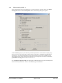
1 Preface .................................................................................................................................. 9
2 Capabilities......................................................................................................................... 10
3 Licence protection and installation .................................................................................. 11
4 Language selection............................................................................................................. 11
5 Starting the program ......................................................................................................... 12
6 Worked example 1: Data input with mouse .................................................................... 13
6.1 System description (Ex. 1) ............................................................................................. 13
6.2 Step 1: Select analysis options (Ex. 1) ........................................................................... 14
6.3 Step 2: Adjust page coordinates (Ex. 1)......................................................................... 15
6.4 Step 3: Define array (Ex. 1) ........................................................................................... 15
6.5 Step 4: Enter surface and pore water pressure points (Ex. 1)......................................... 16
6.6 Step 5: Enter soil layers (Ex. 1)...................................................................................... 17
6.7 Step 6: Enter water levels and loads (Ex. 1)................................................................... 19
6.8 Step 7: Enter soil properties (Ex. 1) ............................................................................... 20
6.9 Step 8: Define reinforced earth wall preferences (Ex. 1) ............................................... 21
6.10 Step 9: Generate geosynthetics (Ex. 1) .......................................................................... 22
6.11 Step 10: Generate slip surfaces (Ex. 1) ......................................................................... 23
6.12 Step 11: Analyse the slope (Ex. 1) ................................................................................. 24
6.13 Step 12: Optimise geosynthetics (Ex. 1) ........................................................................ 25
6.14 Step 13: Evaluate and visualise the results (Ex. 1)......................................................... 26
7 Worked example 2: Data input via editor ....................................................................... 27
7.1 Step 1: Select analysis options (Ex. 2) ........................................................................... 27
7.2 Step 2: Enter system parameters (Ex. 2) ........................................................................ 28
7.2.1 Central dialog box.................................................................................................. 28
7.2.2 Surface points (Ex. 2) ............................................................................................ 29
7.2.3 Soil properties (Ex. 2)............................................................................................ 30
7.2.4 Soil layers (Ex. 2) .................................................................................................. 31
7.2.5 Pore water pressure (Ex. 2).................................................................................... 32
7.3 Step 3: Check and save system (Ex. 2) .......................................................................... 33
7.4 Step 4: Define slip circles (Ex. 2) .................................................................................. 34
7.4.1 Define centre-points (Ex. 2) .................................................................................. 34
7.4.2 Define search grid (Ex. 2)...................................................................................... 35
7.5 Step 5: Analyse slope with circular slip surfaces (Ex. 2) ............................................... 38
7.6 Step 6: Evaluate and visualise the results (Ex. 2)........................................................... 39
7.7 Step 7: Define polygonal slip surfaces (Ex. 2)............................................................... 40
7.7.1 Select analysis method........................................................................................... 40
7.7.2 Define slip bodies using the mouse (Ex. 2) ........................................................... 41
7.7.3 Define slip bodies via editor (Ex. 2) ...................................................................... 41
7.8 Step 8: Analyse slope with polygonal slip surfaces (Ex. 2) ........................................... 42
8 Theoretical principles ........................................................................................................ 43
8.1 DIN 4084:2009 and GGU-STABILITY ........................................................................ 43
8.2 General information on Janbu and Bishop ..................................................................... 47
8.3 General information on General wedge method and Vertical slice method................... 49
GGU-STABILITY User Manual
Page 2 of 172
June 2015
8.4
8.5
8.6
8.7
8.8
Consolidation theory ...................................................................................................... 51
Safety factor definitions ................................................................................................. 53
Passive earth pressure .................................................................................................... 54
Several slip bodies.......................................................................................................... 54
Nail wall or reinforced earth wall .................................................................................. 55
8.8.1 General notes on nail wall analysis........................................................................ 55
8.8.2 Terms ..................................................................................................................... 55
8.8.3 Verification of inner stability................................................................................. 56
8.8.4 Verification of sliding safety ................................................................................. 56
8.8.5 Verification of overturning safety.......................................................................... 57
8.8.6 Verification of bearing capacity safety .................................................................. 58
8.8.7 Verification of general stability ............................................................................. 58
8.8.8 Verification of the concrete shell........................................................................... 58
8.8.9 Maximum nail forces and verification of punching............................................... 60
8.8.10 Construction conditions ......................................................................................... 60
8.9 General notes on analysis with fibre cohesion ............................................................... 61
9 Description of menu items................................................................................................. 63
9.1 File menu........................................................................................................................ 63
9.1.1 "New" menu item................................................................................................... 63
9.1.2 "Load" menu item.................................................................................................. 63
9.1.3 "Save" menu item .................................................................................................. 63
9.1.4 "Save as" menu item .............................................................................................. 63
9.1.5 "Load centre-points"/"Load slip body data" menu items....................................... 63
9.1.6 "Save centre-points"/"Save slip body data" menu items........................................ 63
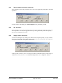
9.1.7 "Printer preferences" menu item............................................................................ 63
9.1.8 "Print and export" menu item ................................................................................ 64
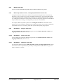
9.1.9 "Batch print" menu item ........................................................................................ 66
9.1.10 "Print output table" menu item............................................................................... 67
9.1.10.1 Selecting the output format ........................................................................... 67
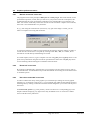
9.1.10.2 Button "Output as graphics".......................................................................... 68
9.1.10.3 Button "Output as ASCII"............................................................................. 70
9.1.11 "Exit" menu item.................................................................................................... 71
9.1.12 "1, 2, 3, 4" menu items........................................................................................... 71
9.2 Editor 1 menu................................................................................................................. 71
9.2.1 "Analysis options" menu item................................................................................ 71
9.2.2 "Enter system parameters" menu item ................................................................... 73
9.2.2.1 "Surface points" button ................................................................................. 74
9.2.2.2 "Soil properties" button ................................................................................. 75
9.2.2.3 "Soil layers" button ....................................................................................... 76
9.2.2.4 "Pore water pressure" button ......................................................................... 77
9.2.2.5 "Permanent loads + live loads" button .......................................................... 78
9.2.2.6 "Point loads" button....................................................................................... 78
9.2.2.7 "Anchors" button........................................................................................... 79
9.2.2.8 "Artesian" button........................................................................................... 80
9.2.2.9 "Earthquake" button ...................................................................................... 80
9.2.2.10 "Dowels" button ............................................................................................ 81
GGU-STABILITY User Manual
Page 3 of 172
June 2015
9.2.2.11 "Soil nails" button ......................................................................................... 82
9.2.2.12 "Geosynthetics" button.................................................................................. 84
9.2.2.13 "Tension members" button ............................................................................ 87
9.2.2.14 "Hor. distributed loads" button...................................................................... 89
9.2.3 "Consolidation layers" menu item ......................................................................... 90
9.2.4 "Structural elements/Encased columns" menu item............................................... 91
9.2.4.1 Structural elements definition........................................................................ 92
9.2.4.2 Encased columns definition........................................................................... 93
9.2.5 "Partial factors, ..." menu item............................................................................... 94
9.2.6 "Project identification" menu item......................................................................... 95
9.2.7 "Geosynthetics table values" menu item................................................................ 95
9.2.8 "Test system" menu item ....................................................................................... 96
9.2.9 "Mirror system" menu item.................................................................................... 96
9.2.10 "Common systems" menu item.............................................................................. 97
9.2.11 "Graphics output preferences" menu item ............................................................. 98
9.2.12 "General legend" menu item.................................................................................. 99
9.2.13 "Soil properties legend" menu item ..................................................................... 100
9.2.14 "Reference staff" menu item................................................................................ 101
9.2.15 "Move objects" menu item................................................................................... 102
9.2.16 "Footing" menu item............................................................................................ 102
9.3 Editor 2 menu............................................................................................................... 103
9.3.1 "Array" menu item............................................................................................... 103
9.3.2 "Surface" menu item ............................................................................................ 103
9.3.3 "Pore water pressure" menu item......................................................................... 103
9.3.4 "Layers" menu item ............................................................................................. 103
9.3.5 "Loads/point loads" menu item............................................................................ 104
9.3.6 "Anchors/dowels/nails/geosynthetics/TM" menu item........................................ 104
9.3.7 "Artesian" menu item........................................................................................... 104
9.3.8 "Water levels" menu item .................................................................................... 105
9.3.9 "Consolidation layers" menu item ....................................................................... 105
9.3.10 "Structural elements/Encased columns" menu item............................................. 105
9.3.11 "Inclinations" menu item ..................................................................................... 105
9.3.12 "Coordinates" menu item..................................................................................... 106
9.3.13 "Stresses" menu item ........................................................................................... 106
9.3.14 "Undo" menu item ............................................................................................... 106
9.3.15 "Restore" menu item ............................................................................................ 106
9.3.16 "Preferences" menu item...................................................................................... 106
9.4 Pwp mesh (pore water pressure mesh) menu ............................................................... 107
9.4.1 Principles ............................................................................................................. 107
9.4.2 "ASCII file" menu item ....................................................................................... 108
9.4.3 "Points to mesh" menu item................................................................................. 109
9.4.4 "Contours" menu item.......................................................................................... 109
9.4.5 "Determine pwp" menu item................................................................................ 109
9.4.6 "Define nodes" menu item ................................................................................... 109
9.4.7 "Change" menu item ............................................................................................ 110
9.4.8 "Move" menu item............................................................................................... 110
GGU-STABILITY User Manual
Page 4 of 172
June 2015
9.4.9 "Edit" menu item.................................................................................................. 110
9.4.10 "Manual meshing" menu item.............................................................................. 111
9.4.11 "Automatic meshing" menu item......................................................................... 111
9.4.12 "Round off" menu item........................................................................................ 111
9.4.13 "Delete" menu item.............................................................................................. 111
9.4.14 "Refine individually" menu item ......................................................................... 112
9.4.15 "Section" menu item ............................................................................................ 113
9.4.16 "All" menu item ................................................................................................... 113
9.5 Centre-points menu (for slip circles only).................................................................... 114
9.5.1 "Define in quadrilateral" menu item .................................................................... 114
9.5.2 "In rectangle" menu item ..................................................................................... 114
9.5.3 "Individually (graphically)" menu item ............................................................... 114
9.5.4 "Individually (editor)" menu item........................................................................ 114
9.5.5 "Refine" menu item.............................................................................................. 114
9.5.6 "Info" menu item ................................................................................................. 114
9.5.7 "Define search grid" menu item........................................................................... 115
9.5.8 "Semi-automatic" menu item ............................................................................... 122
9.5.9 "Delete individually" menu item.......................................................................... 122
9.5.10 "Delete all" menu item......................................................................................... 122
9.5.11 "Display" menu item............................................................................................ 122
9.6 Slip body menu (for polygonal slip surfaces only) ...................................................... 123
9.6.1 "Info" menu item ................................................................................................. 123
9.6.2 "Define new" menu item...................................................................................... 123
9.6.3 "Edit old" menu item ........................................................................................... 124
9.6.4 "Duplicate" menu item......................................................................................... 124
9.6.5 "Edit" menu item.................................................................................................. 124
9.6.6 "Display" menu item............................................................................................ 124
9.6.7 "Delete individually" menu item.......................................................................... 125
9.6.8 "Delete all" menu item......................................................................................... 125
9.6.9 "Logarithmic spiral" menu item........................................................................... 125
9.6.10 "Animation" menu item (General wedge method and
Vertical slice method only).................................................................................. 126
9.6.11 "Move slip body" menu item (General wedge method and
Vertical slice method only).................................................................................. 126
9.7 Safety/Utilisation factors menu (for slip circles only).................................................. 127
9.7.1 General notes ....................................................................................................... 127
9.7.2 "Analyse" menu item ........................................................................................... 127
9.7.3 "Display/details" menu item ................................................................................ 127
9.7.4 "Preferences" menu item...................................................................................... 128
9.7.5 "Show most unfavourable slip circle" menu item................................................ 128
9.7.6 "Specific" menu item ........................................................................................... 128
9.7.7 "All" menu item ................................................................................................... 129
9.7.8 "Contours" menu item.......................................................................................... 130
9.7.9 "Coloured" menu item ......................................................................................... 131
9.8 Safety/Utilisation factors menu (for polygonal slip surfaces only) .............................. 132
9.8.1 General notes ....................................................................................................... 132
9.8.2 "Analyse slip bodies" menu item ......................................................................... 132
GGU-STABILITY User Manual
Page 5 of 172
June 2015
9.8.3
9.8.4
9.8.5
9.8.6
9.8.7
9.8.8
9.8.9
9.8.10
9.8.11
9.8.12
9.8.13
"Show individual slip bodies" menu item............................................................ 133
"All" menu item ................................................................................................... 133
"Display results" menu item ................................................................................ 133
"Analyse intermediate slip bodies" menu item .................................................... 134
"Show" menu item ............................................................................................... 135
"Define slip bodies via lines, rectangles/quadrilaterals" menu item .................... 135
"Slip bodies ... analyse" menu item ..................................................................... 135
"Slip bodies ... show" menu item......................................................................... 135
"Slip bodies ... load/save" menu item .................................................................. 135
"Preferences" menu item...................................................................................... 136
"Force polygon" menu item (General wedge method and
Vertical slice method only).................................................................................. 136
9.8.14 "Displacement diagram" menu item (General wedge method only).................... 136
9.9 Graphics preferences menu .......................................................................................... 137
9.9.1 "Refresh and zoom" menu item ........................................................................... 137
9.9.2 "Zoom info" menu item ....................................................................................... 137
9.9.3 "Pen colour and width" menu item ...................................................................... 137
9.9.4 "Legend font selection" menu item...................................................................... 138
9.9.5 "Mini-CAD toolbar" and "Header toolbar" menu items ...................................... 138
9.9.6 "Toolbar preferences" menu item ........................................................................ 138
9.9.7 "Dimension lines" menu item .............................................................................. 140
9.9.8 "Save graphics preferences" menu item............................................................... 141
9.9.9 "Load graphics preferences" menu item .............................................................. 141
9.10 Page size + margins menu ............................................................................................ 141
9.10.1 "Auto-resize" menu item...................................................................................... 141
9.10.2 "Manual resize (editor)" menu item..................................................................... 141
9.10.3 "Zoom" menu item............................................................................................... 141
9.10.4 "Manual resize (mouse)" menu item.................................................................... 141
9.10.5 "Save coordinates" menu item ............................................................................. 142
9.10.6 "Load coordinates" menu item............................................................................. 142
9.10.7 "Page size and margins" menu item..................................................................... 142
9.10.8 "Font size selection" menu item........................................................................... 142
9.11 Nail wall menu ............................................................................................................. 143
9.11.1 General notes on nail wall input .......................................................................... 143
9.11.2 "Preferences" menu item...................................................................................... 143
9.11.3 "Graphics" menu item.......................................................................................... 145
9.11.4 "Verifications/Safety" menu item ........................................................................ 146
9.11.5 "Nail wall legend" menu item.............................................................................. 147
9.11.6 "Nail force legend" menu item............................................................................. 148
9.11.7 "Enter nails manually" menu item ....................................................................... 148
9.11.8 "Generate" menu item.......................................................................................... 149
9.11.9 "Modify" menu item ............................................................................................ 150
9.11.10 "Optimise" menu item ...................................................................................... 151
9.11.11 "Generate slip surfaces" menu item.................................................................. 151
9.11.12 "Sliding, overturning, bearing failure" menu item ........................................... 152
9.11.13 "Maximum nail forces" menu item................................................................... 152
9.11.14 "Maximum nail forces + punching" menu item................................................ 153
GGU-STABILITY User Manual
Page 6 of 172
June 2015
9.11.15 "Calculate earth pressure + weight" menu item................................................ 155
9.11.16 "Export to GGU-SLAB" menu item................................................................. 156
9.11.17 "Active earth pressure after Culmann" menu item ........................................... 159
9.11.18 "Passive earth pressure after Culmann" menu item.......................................... 160
9.12 ? menu .......................................................................................................................... 161
9.12.1 "Copyright" menu item ........................................................................................ 161
9.12.2 "Help" menu item ................................................................................................ 161
9.12.3 "GGU on the web" menu item ............................................................................. 161
9.12.4 "GGU support" menu item................................................................................... 161
9.12.5 "What's new?" menu item.................................................................................... 161
9.12.6 "Language preferences" menu item ..................................................................... 161
9.12.7 "Kölsch method preferences" menu item............................................................. 161
9.12.8 "Test vibrodisplacement compaction" menu item ............................................... 162
10 Tips and tricks.................................................................................................................. 163
10.1 Keyboard and mouse.................................................................................................... 163
10.2 Function keys ............................................................................................................... 164
10.3 "Copy/print area" icon.................................................................................................. 165
11 Literature.......................................................................................................................... 166
12 Index.................................................................................................................................. 167
List of Tables:
Table 1 Surface points of worked example 1 .................................................................................16
Table 2 Soil properties input screen (examples from GDA recommendation R 2-35 and
Collins et al., 1997) ..........................................................................................................62
List of Figures:
Figure 1 System of worked example 1............................................................................................13
Figure 2 Surface points visualisation (worked example 1)............................................................16
Figure 3 Pore water pressure visualisation (worked example 1) ..................................................17
Figure 4 Layers and soil numbering..............................................................................................17
Figure 5 Soil layers visualisation (worked example 1)..................................................................18
Figure 6 Permanent load visualisation (worked example 1) .........................................................19
Figure 7 Reinforced face (worked example 1) ...............................................................................21
Figure 8 Slip surfaces in system (worked example 1)....................................................................24
Figure 9 Slip bodies with the lowest FOS (worked example 1) .....................................................25
Figure 10 Result after optimisation (worked example 1)...............................................................26
Figure 11 Search grid slip circle radii via start and end radius ...................................................36
Figure 12 Search grid slip circle radii via horizontal tangents.....................................................36
Figure 13 Validity of a tension member (after Figure 2 in DIN 4084:2009) ................................44
GGU-STABILITY User Manual
Page 7 of 172
June 2015
Figure 14 Intermediate slip surface and principle slip surfaces....................................................49
Figure 15 Consolidation layer .......................................................................................................51
Figure 16 Vertical drains...............................................................................................................52
Figure 17 Passive earth pressure wedge .......................................................................................54
Figure 18 Equivalent system for weight calculation......................................................................56
Figure 19 Vertical section for earth pressure determination.........................................................57
Figure 20 Soil dowels ....................................................................................................................81
Figure 21 Soil nails........................................................................................................................82
Figure 22 Geosynthetic ..................................................................................................................84
Figure 23 Geosynthetics with two intersections ............................................................................84
Figure 24 Encased columns - angle input......................................................................................93
Figure 25 Potential lines..............................................................................................................107
Figure 26 Example system for defining the search grid ..............................................................115
Figure 27 Centre-point array 1 ...................................................................................................115
Figure 28 Selected search grid ....................................................................................................117
Figure 29 Results for centre-point array 1 ..................................................................................117
Figure 30 Results for centre-point array 2 ..................................................................................118
Figure 31 Centre-point array 3 ...................................................................................................119
Figure 32 Results for centre-point array 3 ..................................................................................120
Figure 33 Cantilever Wall ...........................................................................................................121
Figure 34 Search grid for cantilever wall....................................................................................121
Figure 35 Result for cantilever wall ............................................................................................122
Figure 36 Face numbering (face 2 and face 4 are nailed) ..........................................................144
Figure 37 Structural system for a solid slab ................................................................................157
Figure 38 Structural system for a horizontally continuous slab ..................................................158
Figure 39 Structural system for a "solo" slab..............................................................................158
GGU-STABILITY User Manual
Page 8 of 172
June 2015
1 Preface
The GGU-STABILITY program system allows slope failure investigations according to German
Standard DIN 4084, DIN 4084:1996 and DIN 4084:2009, using circular slip surfaces (Bishop)
and polygonal slip surfaces (Janbu, General Wedge method and Vertical slice method). Furthermore it is possible to investigate soil nailing and reinforced earth walls. The formulas and relationships given in DIN 4084 are used (see "Theoretical principles" in Section 8).
The fundamentals of analysis using partial factors are given in EC 7/DIN 1054:2010. DIN 4084
contains the calculation procedures (Bishop, Janbu, General wedge method, etc.).
For bending design of the concrete shell according to EC 2, it is possible to export data to the
GGU-SLAB program. Verification of punching according to EC 2 is implemented in the program
module.
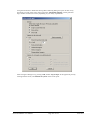
As a speciality, pore water pressure can be entered using not only the usual pore water pressure
line, but also using a pore water pressure mesh. With a pore water pressure mesh, complicated
flow conditions in a slope can be exactly modelled, and taken into consideration for stability calculations. An interface to the groundwater program GGU-SS-FLOW2D is provided.
In 1996 Kölsch developed a constitutive equation for the analysis of slopes in waste materials (see
'The impact of fibrous constituents on the shear strength of domestic waste', Memoranda of the
Leichtweiß Institute for Hydraulic Engineering at the TU Braunschweig, Bulletin 133/96 (Der
Einfluss der Faserbestandteile auf die Scherfestigkeit von Siedlungsabfall). Mitteilungen des
Leichtweiß-Instituts für Wasserbau der TU Braunschweig, Heft 133/96)). This constitutive equation is implemented in GGU-STABILITY as the "Kölsch method" and can be activated for the
corresponding analysis. The theoretical principles are described in the section "General notes on
analysis with fibre cohesion" (see Section 8.9), further literature can be found in Section 11.
The influence of vibrodisplacement compaction after Priebe can be investigated.
The program system allows comfortable data input, which can be carried out almost completely
with the mouse on the screen. A variety of graphical presentation possibilities, to a high standard
of quality, allow you to present the calculation results according to your wishes. Graphic output
supports the true-type fonts supplied with WINDOWS, so that excellent layout is guaranteed.
Colour output and any graphics (e.g. files in formats BMP, JPG, PSP, etc.) are supported. DXF
files can also be imported by means of the integrated Mini-CAD module (see the "Mini-CAD"
manual).
The program has been thoroughly tested. No faults have been found. Nevertheless, liability for
completeness and correctness of the program and the manual, and for any damage resulting from
incompleteness or incorrectness, cannot be accepted.
GGU-STABILITY User Manual
Page 9 of 172
June 2015
2 Capabilities
The GGU-STABILITY program has the following capabilities:
Surface line with a maximum of 100 surface points
100 pore water pressure points
100 layers (no layer polygon input necessary !!!)
50 anchors
50 soil dowels
50 soil nails
50 geosynthetics
150 tension members
50 soils
50 point loads
40 permanent and/or live loads
50 horizontal distributed loads
1000 slices
5000 slip circle centre-points with any amount of radii
2500 polygonal slip bodies with a maximum of 200 polygon course points
Polygonal slip surfaces after Janbu, General wedge method and Vertical slice method
Safety statement after the principle of virtual movements for General wedge method (Goldscheider and Gudehus)
Variation between two boundary slip bodies for polygonal slip bodies
Exact consideration of pore water pressures via a pore water pressure mesh possible (optional)
Interface to the groundwater modeller GGU-SS-FLOW2D for automatic import of pore
water pressure mesh
ASCII interface for automatic import of a pore water pressure mesh from third-party
groundwater modellers
Complete input and correction of system geometry possible using the mouse
Consideration of passive earth pressure wedge (optional)
Consideration of structural elements
Consideration of vibrodisplacement compaction after Priebe
Use of any true-type fonts, guaranteeing an excellent layout
Colour presentation of almost all system geometry. The colours can be freely specified by
the user. In particular, the soil layers can be colour-filled. The colours can also be specified
in accordance with DIN 4022 conventions.
Zoom function
"Mini-CAD" system (additional labelling, lines, rectangles, circles, graphics etc.)
DXF import via "Mini-CAD"
GGU-STABILITY User Manual
Page 10 of 172
June 2015
The program works on the principle of What you see is what you get. This means that the
screen presentation represents, on the whole, that which you will see on your printer. It also
means that you can have the current screen contents sent to the printer at any stage during
processing.
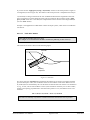
3 Licence protection and installation
In order to guarantee a high degree of quality, a hardware-based copy protection system is used
for the GGU-STABILITY program.
The GGU software protected by the CodeMeter copy protection system is only available in
conjunction with the CodeMeter stick copy protection component (hardware for connection to the
PC, "CM stick"). Because of the way the system is configured, the protected software can only be
operated with the corresponding CM stick. This creates a fixed link between the software licence
and the CM stick copy protection hardware; the licence as such is thus represented by the CM
stick. The correct Runtime Kit for the CodeMeter stick must be installed on your PC.
Upon start-up and during running, the GGU-STABILITY program checks that a CM stick is
connected. If it has been removed, the program can no longer be executed.
For installation of GGU software and the CodeMeter software please refer to the information in
the Installation notes for GGU Software International, which are supplied with the program.
4 Language selection
GGU-STABILITY is a multilingual program. The program always starts with the language setting applicable when it was last ended.
The language preferences can be changed at any time in the "?" menu, using the menu item "Language preferences" (in German: "Spracheinstellung", in Spanish: "Configuración de idioma").
GGU-STABILITY User Manual
Page 11 of 172
June 2015
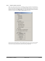
5 Starting the program
After starting the program, you will see two menus at the top of the window:
File
?
After clicking the "File" menu, either an existing file can be loaded by means of the "Load" menu
item, or a new system can be created using "New".
The program allows simple system input by moving directly to the "Editor 1/Common systems"
menu item after "New" is clicked (see Section 9.2.10). The dialog box in this case is expanded
somewhat to allow you to select the applicable standard and the required analysis method ("Bishop", etc.).
If you do not want to work with the "Common systems" dialog box, click "No" in the query box
or "Cancel" in the subsequent boxes. You will then return to the home screen. The program default standard is "EC 7" and the analysis method used employs circular slip surfaces after
"Bishop". You then see ten menus in the menu bar:
File
Editor 1
Editor 2
Pwp mesh
Centre-points/Slip body
Safety factors/Utilisation factors
Graphics preferences
Page size + margins
Nail wall
?
After clicking one of these menus, the so-called menu items roll down, allowing you access to all
program functions.
The program works on the principle of What you see is what you get. This means that the screen
presentation represents, overall, what you will see on your printer. In the last consequence, this
would mean that the screen presentation would have to be refreshed after every alteration you
make. For reasons of efficiency and as this can take several seconds for complex screen contents,
the GGU-STABILITY screen is not refreshed after every alteration.
If you would like to refresh the screen contents, press either [F2] or [Esc]. The [Esc] key additionally sets the screen presentation back to your current zoom, which has the default value 1.0,
corresponding to an A3 format sheet.
GGU-STABILITY User Manual
Page 12 of 172
June 2015
6 Worked example 1: Data input with mouse
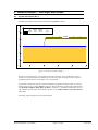
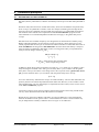
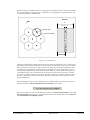
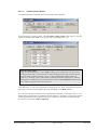
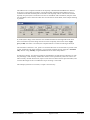
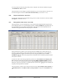
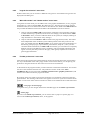
6.1
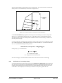
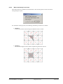
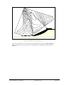
System description (Ex. 1)
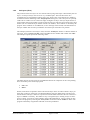
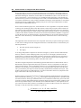
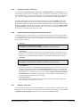
The following simple slope shall be calculated using Janbu's method:
15
Soil
10
,k
[°]
30.00
35.00
c,k
[kN/m²]
0.00
0.00
,k
[kN/m³]
20.00
19.00
Designation
Silt
Sand
ps ps==5.00
5.00
5
0
-5
-10
-15
-10
0
10
20
30
Figure 1 System of worked example 1
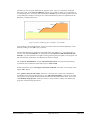
We have a 6.0 m high slope, to be reinforced with geosynthetics. The groundwater level is at
surface level. The system has two differing soils. The soil properties are given in the legend. A
permanent load of 5 kN/m² on the slope is to be considered.
In principle, system input can be carried out manually using direct numerical input, or with the
mouse on the screen, or with a mixture of the two. Direct numerical system input is described in
the "Worked example 2: Data input via editor" in Section 7. All further explanations concerning numerical system input can be found in Section 9.2.2 ("Editor 1/Enter system parameters"
menu item).
Following, input with the mouse will be described.
GGU-STABILITY User Manual
Page 13 of 172
June 2015
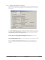
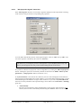
6.2
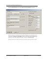
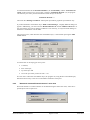
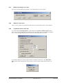
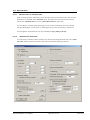
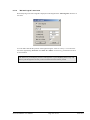
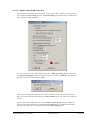
Step 1: Select analysis options (Ex. 1)
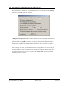
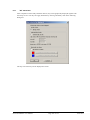
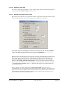
After starting the program the logo is at first displayed. Select the menu item "File/New" and leave
the dialog box "Common systems" with "No". The "Analysis options" dialog box, which can
also be accessed via the "Editor 1" menu, opens for input.
The default setting is the "EC 7" standard and the "Bishop (circles/slices)" calculation method.
For the example select "Janbu (polygons/slices)" as the calculation method.
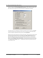
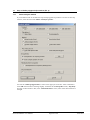
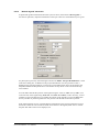
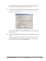
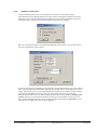
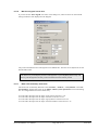
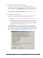
After confirming with "OK" you will see a dialog box, in which you can enter the partial safety
factors (see also Section 9.2.5). Using the "To DIN 1054:2010" button in the "Default values"
group box, you can accept the partial factors for the various load cases. The partial factors for
DS-P are used in this example.
GGU-STABILITY User Manual
Page 14 of 172
June 2015
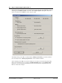
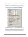
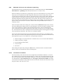
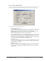
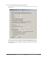
6.3
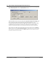
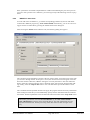
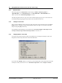
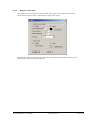
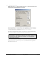
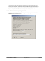
Step 2: Adjust page coordinates (Ex. 1)
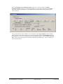
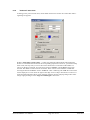
The program default coordinates do not fit the system and must be altered. Select the menu item
"Manual resize (editor)" from the "Page size + margins" menu.
Enter the values from the above dialog box.
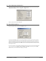
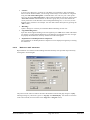
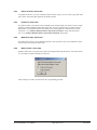
6.4
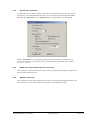
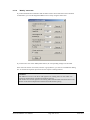
Step 3: Define array (Ex. 1)
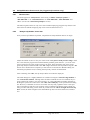
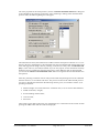
Select the "Array" menu item from the "Editor 2" menu.
Activate the "Use array" check box. This ensures that the cross hairs snap onto these points during the following input with the mouse. This makes input of slope geometry easier. If you have a
geometry which does not lend itself to being forced into such an array, do without activating the
check box. Leave the dialog box with "OK". The array will be displayed after selecting one of the
following menu items.
If you own a scanner you can produce a bitmap file of the system to be processed. This bitmap file
can be imported using "Graphics preferences/Mini-CAD toolbar" menu item (see the "MiniCAD" manual). You can thus further simplify system input.
GGU-STABILITY User Manual
Page 15 of 172
June 2015
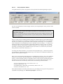
6.5
Step 4: Enter surface and pore water pressure points (Ex. 1)
Select the "Surface" menu item from the "Editor 2" menu. You will first see an info box with
possible ways of entering surface geometry. Then click on the surface line coordinates with the
left mouse button. They will be continuously numbered from left to right. Erroneous input can be
corrected by clicking with the right mouse button, or be undone by using the [Backspace]-key.
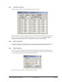
For this example, click on the following four coordinate pairs:
x [m]
y [m]
-15.0
0.0
0.0
0.0
15.0
6.0
30.0
6.0
Table 1 Surface points of worked example 1
Figure 2 Surface points visualisation (worked example 1)
GGU-STABILITY User Manual
Page 16 of 172
June 2015
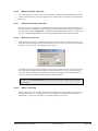
Select the "Pore water pressure" menu item from the "Editor 2" menu. Enter the pore water
pressure line in analogy to the surface line. From the difference between a slice toe and the height
position above this toe point of the pore water pressure line, the program later calculates the pore
water pressure on the slice.
For this example, select a horizontal pore water pressure line at 0.0 m, which begins at x = -15 m
and ends at x = +30 m and thus consists of two points only.
Figure 3 Pore water pressure visualisation (worked example 1)
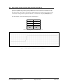
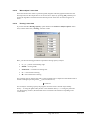
6.6
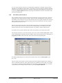
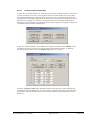
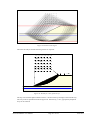
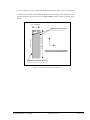
Step 5: Enter soil layers (Ex. 1)
Select the "Layers" menu item from the "Editor 2" menu. A layer always consists of two coordinate pairs. Unlike many other programs, with GGU-STABILITY it is not necessary to enter a
polygon course across the whole width of the system. Each layer has a soil number which is used
to describe the soil properties (see second dialog box in Section 6.8). These soil properties are
valid above the two coordinate pairs, as far as the surface line, or as far up as the base of a further
layer. After input the layers are sorted automatically by depth and numbered. The soil number
assigned to a layer is unaffected by the layer numbering (see Figure 4).
Figure 4 Layers and soil numbering
GGU-STABILITY User Manual
Page 17 of 172
June 2015
During input, observe that the layer boundaries may not cross. Nor are they allowed to intersect
the surface. Both of these conditions are checked by the program immediately after layer input.
Erroneous input is corrected or rejected and an error message displayed.
For this example, select two layers with the coordinates:
Layer 1 with soil number 1
x/y (left) = 0.0/0.0
x/y (right) = 30.0/0.0
Layer 2 with soil number 2
x/y (left) = -15.0/-12.0
x/y (right) = 30.0/-12.0
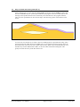
Figure 5 Soil layers visualisation (worked example 1)
GGU-STABILITY User Manual
Page 18 of 172
June 2015
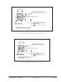
6.7
Step 6: Enter water levels and loads (Ex. 1)
For calculation of the horizontal and the vertical water pressure above slope areas, the program
also requires the water levels at the front left and front right of the slope. When the program starts
the default values are 0.0 m (see first dialog box in Section 6.8). Water levels can be defined using
the left or right mouse button after pointing to "Editor 2/Water levels" menu item. The example
contains a slope without dammed water, so these values need not be altered.
The permanent load of 5 kN/m² for the example system is defined with the mouse in analogy to
the previous input, using the menu item "Editor 2/Loads/point loads". First select the type of
load from the dialog box. Click the "Permanent loads" button for the example used here. You
will then see information on implementation; click the upper left and right slope points. Enter
5 kN/m² as the load for both sides in the following dialog box.
Figure 6 Permanent load visualisation (worked example 1)
GGU-STABILITY User Manual
Page 19 of 172
June 2015
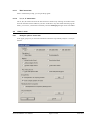
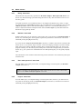
6.8
Step 7: Enter soil properties (Ex. 1)
The slope geometry has now been described. Now, you only need to enter the soil properties.
Select the "Enter system parameters" menu item from the "Editor 1" menu. You will see a dialog box for manual input of the system parameters. The values in brackets following the respective
item show how many points, layers, etc. have been defined.
Select the "Soil properties [x]" button and click on the "1 soil(s) to edit" button in the dialog box.
Enter the value "2" into the dialog box and confirm with "OK". Enter the soil properties given in
the following dialog box.
When complete, leave this box and the box above using the "Done" button.
GGU-STABILITY User Manual
Page 20 of 172
June 2015
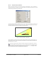
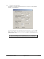
6.9
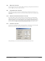
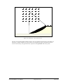
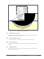
Step 8: Define reinforced earth wall preferences (Ex. 1)
Select the "Nail wall/Preferences" menu item and activate the "Calculate wall" check box. In the
"Wall consists of:" group box select "Geosynthetics" as the nailing element.
The faces are sections of the defined terrain polygon course. They are continuously numbered
from left to right. By assigning the (face) number you define which section of the terrain polygon
course is the reinforced slope face (also see Figure 36 in Section 9.11.2). Assign the number 2 for
"Face 1" because this is the reinforced face in the worked example. Confirm the remaining defaults with "OK".
Figure 7 Reinforced face (worked example 1)
GGU-STABILITY User Manual
Page 21 of 172
June 2015
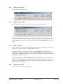
6.10 Step 9: Generate geosynthetics (Ex. 1)
Go to the "Nail wall/Generate" menu item. You will see the following dialog box. If geosynthetics have already been generated, activate the "Delete current geosynthetics" check box.
Enter the values shown in the dialog box and confirm with "OK". Six new geosynthetics are generated. After confirming the corresponding message box, a new prompt appears immediately. If
you answer the "Generate new slip surfaces?" query with "No", the new geosynthetics are represented in the system and the defined values listed in a table in the "Nail force legend".
Normally and thus for the example, answer the query for the slip surface generation with "Yes".
GGU-STABILITY User Manual
Page 22 of 172
June 2015
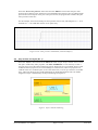
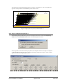
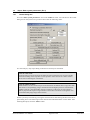
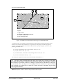
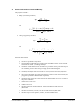
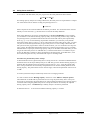
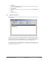
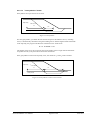
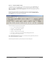
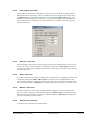
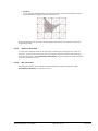
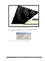
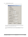
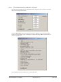
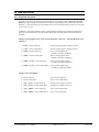
6.11 Step 10: Generate slip surfaces (Ex. 1)
After answering the "Generate new slip surfaces?" query with "Yes" a dialog box opens, which
can also be reached via the "Nail wall/Generate slip surfaces" menu item (see Section 9.11.11).
Slip surfaces with 2 polygonal sections are generated (two-wedge failure mechanism).
In the upper group box of the dialog box, define the inclinations of the rear slip line, responsible
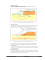
for the active earth pressure acting on the system. The two inclinations given are used as limit
values. The number of subdivisions used is given by "No. of subdivisions".
Define the location of the front slip line in the lower group box. The lowest slip lines always begin
at the base of the wall and end at the tips of the nails. If the "Only of lowest nail" check box is
deactivated, additional slip lines are also generated from the soil nails above. These lines will
begin at the head of the respective nails or at a given distance below this; you can specify this
distance with "Starting point under nail head [m]". The slip lines end at the nail foot if the slip
line has a positive inclination, otherwise the slip line is rejected (except for the lowest nail). If the
"No. of intersections with nail" value is > 0, additional slip surfaces are generated, which intersect the respective nail.
GGU-STABILITY User Manual
Page 23 of 172
June 2015
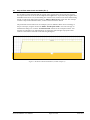
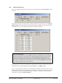
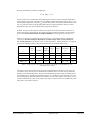
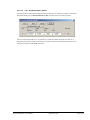
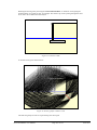
The number of newly generated slip surfaces is shown in a message box. After closing the message box the slip surfaces are immediately shown on the screen.
218
217
216
215
214
213
212
211
210
209
208
207
206
205
204
203
255
254
253
252
251
250
249
248
247
246
245
244
243
242
241
240
239
238
237
236
235
234
233
232
231
230
229
228
227
226
225
224
223
222
221
220
219
373
372
371
370
369
368
367
366
365
364
363
362
361
360
359
358
357
356
355
354
353
352
351
275
274
273
272
350
349
348
347
271
270
269
268
346
345
344
343
267
266
265
264
342
341
340
339
263
262
261
260
338
337
336
335
259
258
257
256
287
39
202
20
201
38
286
19
285
36
284
200
37
16
199
35
198
18
283
15
282
32
281
280
197
34
12
196
31
195
17
14
194
279
11
278
28
33
277
276
193
30
8192
191
27
13
10
190
24
29
7118
26
4 117
23
96 44
25
3 22
150
149
96
300
299
59
95
148
58
94
147
93
298
297
55
296
146
92
57
144
145
54
91
143
89
295
294
51
56
293
142
292
88
53
90
140
141
50
87
139
85
291
290
47
52
289
138
288
84
49
86
136
137
46
83
135
81
43
48
134
80
45
82
133
42
79
41
78
40
334
333
189
188
332
331
330
187
329
185
186
184
328
327
326
183
325
181
182
180
324
323
322
179
321
177
178
176
320
319
318
175
317
173
174
172
171
170
316
169
116
168
315
314
313
167
115
166
114
112
165
312
311
310
164
111
309
113
162
163
110
108
161
308
307
306
160
107
305
109
158
159
106
104
157
304
303
302
156
103
301
105
154
155
102
100
153
152
99
101
151
98
97 52 21
132
77
76
131
130
75
129
74
128
73
127
71
126
70
72
124
125
69
123
67
122
66
68
120
121
65
119
63
62
64
61
60
373
370
371
372
366
367
368
369
362
363
364
365
358
359
360
361
354
355
356
357
351
352
353
347
348
349
350
343
344
345
346
339
340
341
342
335
336
337
338
287
284
285
286
280
281
282
283
276Geos 6/µ:0.90/R,d:14.5
277
278
279
299
300
296
297
298
292
293
294
295
288
289
290
291
333
334
329
330
331
332
325
326
327
328
321
322
323
324
317
318
319
320
316
313
314
315
309
310
311
312
305
306
307
308
301
302
303
304
1
ps = 5.00
354
355
356
357
358
359
360
361
362
363
364
365
366
367
368
369
370
371
372
373
218
253
254
255
235
236
272
273
274
275
215
216
217
249
250
251
252
231
232
233
234
268
269
270
271
202
201
214
211
212
213
245
246
247
248
227
228
229
230
264
265
266
267
198
199
200
207
208
209
210
241
242
243
244
223
224
225
226
263
260
261
262
194
195
196
197
203
204
205
206
237
238
239
240
219Geos 5/µ:0.90/R,d:14.5
220
221
222
256
257
258
259
193
190
191
192
256
257
258
259
260
261
262
263
264
265
266
267
268
269
270
271
272
273
274
275
335
336
337
338
339
340
341
342
343
344
345
346
347
348
349
350
351
352
353
149
150
186
187
188
189
167
168
169
132
145
146
147
148
182
183
184
185
166
163
164
165
129
130
131
141
142
143
144
178
179
180
181
159
160
161
162
128
125
126
127
137
138
139
140
177
174
175
176
155
156
157
158
121
122
123
124
133
134
135
136
170
171
172
173
151Geos 4/µ:0.90/R,d:14.5
152
153
154
120
117
118
119
170
171
172
173
174
175
176
177
178
179
180
181
182
183
184
185
186
187
188
189
237
238
239
240
241
242
243
244
245
246
247
248
249
250
251
252
253
254
255
317
318
319
320
321
322
323
324
325
326
327
328
329
330
331
332
333
334
94
95
96
116
113
114
115
76
77
90
91
92
93
112
109
110
111
72
73
74
75
86
87
88
89
108
105
106
107
68
69
70
71
82
83
84
85
104
101
102
103
64
65
66
67
78
79
80
81
100
97Geos 3/µ:0.90/R,d:14.5
98
99
60
61
62
63
37
38
39
59
56
57
58
36
33
34
35
52
53
54
55
29
30
31
32
51
48
49
50
25
26
27
28
47
44
45
46
24
21
22
23
40 Geos 2/µ:0.90/R,d:14.5
41
42
43
5
6
7
8
1 Geos 1/µ:0.90/R,d:14.5
2
3
4
100
101
102
103
104
105
106
107
108
109
110
111
112
113
114
115
116
151
152
153
154
155
156
157
158
159
160
161
162
163
164
165
166
167
168
169
219
220
221
222
223
224
225
226
227
228
229
230
231
232
233
234
235
236
301
302
303
304
305
306
307
308
309
310
311
312
313
314
315
316
97
98
99
133
134
135
136
137
138
139
140
141
142
143
144
145
146
147
148
149
150
203
204
205
206
207
208
209
210
211
212
213
214
215
216
217
218
288
289
290
291
292
293
294
295
296
297
298
299
300
40
41
42
43
44
45
46
47
48
49
50
51
52
53
54
55
56
57
58
59
78
79
80
81
82
83
84
85
86
87
88
89
90
91
92
93
94
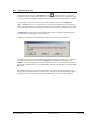
95
96
17
18
19
20
13
14
15
16
10
11
12
9
117
118
119
120
121
122
123
124
125
126
127
128
129
130
131
132
190
191
192
193
194
195
196
197
198
199
200
201
202
276
277
278
279
280
281
282
283
284
285
286
287
10
11
12
13
14
15
16
17
18
19
20
21
22
23
24
25
26
27
28
29
30
31
32
33
34
35
36
37
38
39
60
61
62
63
64
65
66
67
68
69
70
71
72
73
74
75
76
77
1
2
3
4
5
6
7
8
9
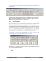
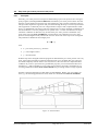
Figure 8 Slip surfaces in system (worked example 1)
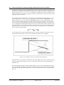
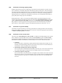
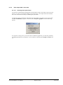
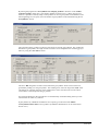
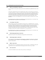
6.12 Step 11: Analyse the slope (Ex. 1)
After defining the slip bodies the system can be analysed. Select the menu item "Analyse slip
bodies" from the "Utilisation factors" menu. The following note is shown:
If the slip surface coincides with the geosynthetics, the tangent of the friction angle is multiplied
by the geosynthetics reduction factor µ and correspondingly adopted for analysis. After confirming the note the following dialog box opens:
GGU-STABILITY User Manual
Page 24 of 172
June 2015
Adjust the number of slices to suit your wishes. If the "Test passive earth pressure wedge" check
box is activated, the program will examine whether gradients greater than 45° - /2 occur in the
passive earth pressure region of the respective slip body. These slip bodies will not be investigated. Slip body movement should to the "left". Begin calculation of all slip bodies using the "All"
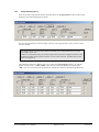
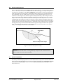
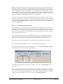
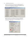
button. Once calculations are complete you will be shown some statistics.
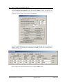
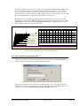
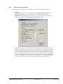
Beside stability, the maximum geosynthetics forces resulting from slip body variation are determined. After confirming with "OK", the slip body with the lowest FOS is displayed. In the "Utilisation factors" menu, point at the "Show individual slip bodies" or "All" menu items in order to
display other slip bodies or, indeed, all slip bodies.
Geosynthetics
Geos 6/µ:0.90/R,d:14.5
Geos 5/µ:0.90/R,d:14.5/F:0.0
5/µ:0.90/R,d:14.5
Geos 4/µ:0.90/R,d:14.5
4/µ:0.90/R,d:14.5/F:14.5
R0
[kN/m]
EN,d
[kN/m]
[-]
SB no.
[-]
EE,d
[kN/m]
max E d
[kN/m]
Rd
[kN/m]
µG
[-]
Geos.
0.00
14.65
0.99
198
-
14.65
14.52
1.01
Fortrac
35/20-20 T
0.90
0.00
15.27
0.95
277
-
15.27
14.52
1.05
Fortrac
35/20-20 T
6.00
0.90
0.00
15.48
0.94
192
-
15.48
14.52
1.07
Fortrac
35/20-20 T
2.50
6.00
0.90
0.00
15.48
0.94
192
-
15.48
14.52
1.07
Fortrac
35/20-20 T
2
1.50
6.00
0.90
0.00
15.48
0.94
192
-
15.48
14.52
1.07
Fortrac
35/20-20 T
1
0.50
6.00
0.90
0.00
15.48
0.94
192
-
15.48
14.52
1.07
Fortrac
35/20-20 T
Nr.
Depth
[m]
L
[m]
6
5.50
5
4.50
6.00
4
3.50
3
[-]
6.00
ps
= 5.000.90
Geos 3/µ:0.90/R,d:14.5/F:14.5
3/µ:0.90/R,d:14.5
Geos 2/µ:0.90/R,d:14.5/F:14.5
2/µ:0.90/R,d:14.5
Geos 1/µ:0.90/R,d:14.5
1/µ:0.90/R,d:14.5/F:14.5
EE,d = force on outer skin from earth pressure
EN,d = force from failure mechanism (divided by ). ( = 1 / µ)
f = · tan( ) · ' (Standard: EC 7 / Geo = 1.40)
Figure 9 Slip bodies with the lowest FOS (worked example 1)
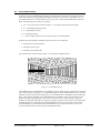
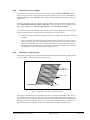
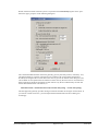
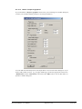
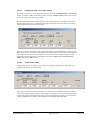
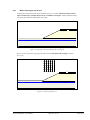
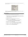
6.13 Step 12: Optimise geosynthetics (Ex. 1)
The used geosynthetics will lead to an unstable slope. Use the menu item "Nail wall/optimise" to
find the optimum geosynthetics. The following dialog box opens:
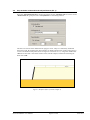
Adopt the preferences and start optimisation of all geosynthetics. The result with optimum geosynthetics will be shown in a message box. Adopt the new geosynthetics with "OK". Then, restart
the slope analysis using "Utilisation factors/Analyse slip bodies" menu item.
GGU-STABILITY User Manual
Page 25 of 172
June 2015
Geosynthetics
Geos 6/µ:0.90/R,d:23.0
Geos 5/µ:0.90/R,d:23.0
Geos 4/µ:0.90/R,d:23.0/F:0.0
4/µ:0.90/R,d:23.0
R0
[kN/m]
EN,d
[kN/m]
[-]
SB no.
[-]
EE,d
[kN/m]
max Ed
[kN/m]
Rd
[kN/m]
µG
[-]
Geos.
0.00
18.32
1.26
284
-
18.32
23.02
0.80
Fortrac
55/30-20 T
0.90
0.00
20.80
1.11
277
-
20.80
23.02
0.90
Fortrac
55/30-20 T
6.00
0.90
0.00
21.54
1.07
192
-
21.54
23.02
0.94
Fortrac
55/30-20 T
2.50
6.00
0.90
0.00
21.77
1.06
118
-
21.77
23.02
0.95
Fortrac
55/30-20 T
2
1.50
6.00
0.90
0.00
21.77
1.06
118
-
21.77
23.02
0.95
Fortrac
55/30-20 T
1
0.50
6.00
0.90
0.00
21.77
1.06
118
-
21.77
23.02
0.95
Fortrac
55/30-20 T
Nr.
Depth
[m]
L
[m]
6
5.50
5
4.50
6.00
4
3.50
3
[-]
6.00
ps
= 5.000.90
Geos 3/µ:0.90/R,d:23.0/F:23.0
3/µ:0.90/R,d:23.0
Geos 2/µ:0.90/R,d:23.0/F:23.0
2/µ:0.90/R,d:23.0
Geos 1/µ:0.90/R,d:23.0/F:23.0
1/µ:0.90/R,d:23.0
EE,d = force on outer skin from earth pressure
EN,d = force from failure mechanism (divided by ). ( = 1 / µ)
f = · tan() · ' (Standard: EC 7 / Geo = 1.40)
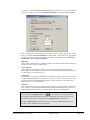
Figure 10 Result after optimisation (worked example 1)
Using the new geosynthetics an adequate utilisation factor can be achieved.
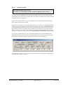
6.14 Step 13: Evaluate and visualise the results (Ex. 1)
If you wish, you can now calculate safety against sliding, overturning and bearing capacity failure
(menu item "Nail wall/Sliding, overturning, bearing failure", see Section 9.11.12). The active
earth pressure on the reinforced earth wall, which is required for the three verifications, is then
calculated with cohesion.
A further evaluation can be carried out using the menu items "Nail wall/Maximum nail forces"
(Section 9.11.13) or "Nail wall/Maximum nail forces + punching" (Section 9.11.14) and "Nail
wall/Calculate earth pressure + weight" (Section 9.11.15).
All principal data and results will be displayed in legends on the output sheet. Position the legends
to suit your taste using the menu item "Editor 1/Move objects" (Section 9.2.15) or using the
mouse after pressing [F11]. The legends can be most easily edited and modified by doubleclicking with the left mouse button and then entering your preferences into the editor boxes.
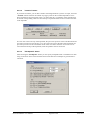
Enter a company letterhead. To do this, activate the Mini-CAD system by pointing to "Graphics
preferences/Header toolbar" and load the example file "GGU-STABILITY-e.kpf" using the
smart icon in the pop-up menu. If desired, save the file to your hard drive (menu item
"Load"
"File/Save as", Section 9.1.4).
GGU-STABILITY User Manual
Page 26 of 172
June 2015
7 Worked example 2: Data input via editor
7.1
Step 1: Select analysis options (Ex. 2)
Experience has shown that data input via editor is generally only used to correct geometry entered
using the mouse. Nonetheless, this input method shall be demonstrated on a somewhat more complicated example. To improve understanding, you should follow the explanation in parallel on
your computer.
After starting the program the logo is at first displayed. Select the menu item "File/New" and leave
the dialog box "Common systems" with "No". The "Analysis options" dialog box, which can
also be accessed via the "Editor 1" menu, opens for input. The default setting is the "EC 7" standard and the "Bishop (circles/slices)" calculation method.
After confirming with "OK" you will see a dialog box, in which you can enter the partial safety
factors. Using the "To DIN 1054:210" button in the "Default values" group box, you can accept
the partial factors given in the EC 7 for the various load cases. The partial factors for load case
DS-P are used in this example.
If you have already worked with the program check and, where necessary, activate the mentioned
switches in the "Editor 1/Analysis options" menu item.
GGU-STABILITY User Manual
Page 27 of 172
June 2015
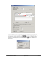
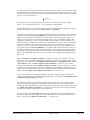
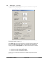
7.2
7.2.1
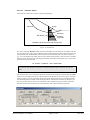
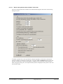
Step 2: Enter system parameters (Ex. 2)
Central dialog box
Go to the "Enter system parameters" item in the "Editor 1" menu. You will then see the central
dialog box for the system to be processed. Now enter the following values.
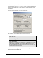
For wall analyses, only slopes failing to the left can currently be considered.
Note on water levels:
From the water levels the program calculates the water load in the area of a slice and the
horizontal loading of the slope due to water pressure. If the water level is below surface
level it has no meaning for calculations.
Note on number of slices:
Small numbers of slices mean low precision and shorter calculation times. Large slice numbers mean a correspondingly longer calculation time and higher precision. The minimum
number of slices is also dependent upon the complexity of the slope. A slope which is
heavily layered will require a larger number of slices than one which is homogenous. We
recommend analysing using at least 50 slices.
Further system input is made by pressing the relevant buttons and entering the data in the subsequent dialog boxes. The following sections describe the individual buttons in more detail. After
finishing data input, select the "Done" button.
GGU-STABILITY User Manual
Page 28 of 172
June 2015
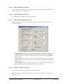
7.2.2
Surface points (Ex. 2)
Next, the coordinates of the surface points must be specified. Select the "Surface points" button
to do this.
The example system has 8 surface points. To edit the number of surface points, select "0 surface
point(s) to edit". Then enter 8 as new number and confirm with "OK". You can now enter the 8
coordinate pairs (x/y). The example requires input of the following values:
Note on surface points:
After leaving the dialog box (via the "Done" button), the coordinate pairs will be sorted according to increasing x-values. This allows simple deleting and inserting of surface points.
You can delete a point by entering a "large" x-value and then reducing the number of
points by 1. Inserting a point is achieved by increasing the number of points by 1 and then
entering the coordinate pair at the end of the table. You can edit superfluous surface points
even simpler using the mouse (see Section 6.5).
In the dialog box, 32 value pairs maximum are displayed at once. If the system has more than 32
value pairs, you can move through the table with the "Forw." and "Back" buttons.
It is even easier to import surface points via the Windows clipboard. For example, if the x/y coordinates of the surface points are available in an Excel table, it is possible to copy the two columns
containing the data into the clipboard ("Edit/Copy") and then to paste them into the dialog box
shown above by pressing "Import clipboard".
GGU-STABILITY User Manual
Page 29 of 172
June 2015
7.2.3
Soil properties (Ex. 2)
Next, the system soil properties must be specified. Press the "Soil properties" button in the central
dialog box. The following dialog box opens:
For each soil information on friction angle, cohesion, unit weight and pore water pressure coefficient are needed.
In saturated zones you enter unit weight of saturated soil. In unsaturated zones you enter
unit weight of wet soil.
Under no circumstances may, for the unit weight, the buoyant unit weight be entered, as the
program considers vertical water pressures via pore water pressures, and thus achieves the
most exact approach.
The example system has 3 differing soils. First, select the "Soil properties" button. To edit the
number of soils, select "x soil(s) to edit". Then enter 3 as the new number and confirm with
"OK". You can now enter the soil properties for example 2 as shown in the following dialog box:
GGU-STABILITY User Manual
Page 30 of 172
June 2015
7.2.4
Soil layers (Ex. 2)
The positions of the soils layers are now entered. The layering of the slope is described by the soil
layers. A soil layer always consists of two x/y coordinate pairs. The area above these two
coordinate pairs is assigned the properties of the soil, which is also to be entered (as a number in
accordance with the numbering in the "Soil properties" dialog box). The soil layers are upwardly
valid as far as surface level or to the lower edge of a higher soil layer. Soil layer input must be in
such a manner that in all possible vertical sections the soil layer which is above has the lower layer
number (do not confuse the layer number with the soil number!). This condition is checked by the
program. If this condition is not adhered to, an error message will be issued, with information on
the layer number and correction possibilities. Erroneous input is therefore not possible.
The example system has 10 soil layers. First, select the "Soil layers" button. To edit the number of
soil layers, select "x layer(s) to edit". Then enter 10 as the new number and confirm with "OK".
The example requires input of the following values:
The dialog box for the soil layers has two additional buttons in comparison to the corresponding
boxes for surface points and soil properties
"Cut" and
"Paste".
Further, small boxes are placed in front of each of the layer values. In order to delete a layer you
must click on the box of the layer to be deleted and then select the "Cut" button. The layer will
then be deleted. The layer values are copied to an internal buffer and used as the new values for a
layer if a "Paste" is necessary. This makes it easy to reorganise layers. Pasting of layer is analogous to cutting. A new layer will be pasted in front of the marked layer. Correct sorting can also
be left to the program by selecting the "Test system" menu item from the "Editor 1" menu. The
program will find any irregularities and offer correction possibilities.
GGU-STABILITY User Manual
Page 31 of 172
June 2015
It is even easier to import soil layers via the Windows clipboard. For example, if the soil strata
information is available in an Excel table, it is possible to copy the respective columns containing
the data into the clipboard ("Edit/Copy") and then to paste them into the dialog box shown above
by pressing "Import clipboard". Before importing the information, select the soil number of the
strata layer being pasted.
7.2.5
Pore water pressure (Ex. 2)
The coordinates of the pore water pressure line are entered as a polygon course. The x-values of
the polygon course must increase from left to right. From the vertical distance between the slice
foot and the point on the pore water pressure line above this, the program calculates the valid pore
water pressure (u) for the slice. If the pore water pressure line lies below the slice foot, the pore
water pressure will be set to zero.
The pore water pressure line must cover the whole of the area to be investigated in the calculations. If no pore water pressures are present you can simply define a pore water pressure line
which consists of two points, and which runs below any possible y-values of the slice feet.
If a phreatic line is present within the slope, this line is generally a pore water pressure line.
The example system has 5 pore water pressure points. First, select the "Pore water press." button
in the central dialog box and then, alter the number of pore water pressure points to 5 using the "x
pwp point(s) to edit" button. Enter the values shown in the following dialog box:
For deleting and pasting of pore water pressure points see the note in "Surface points" (Section 7.2.2).
The pore water pressure points can also be imported via the Windows clipboard. For example, if
the x/y coordinates of the pore water pressure points are available in an Excel table, it is possible
to copy the two columns containing the data into the Windows clipboard ("Edit/Copy") and then
to paste them into the dialog box shown above by pressing "Import clipboard".
GGU-STABILITY User Manual
Page 32 of 172
June 2015
7.3
Step 3: Check and save system (Ex. 2)
After finishing input, you can select the "Test system" menu item from the "Editor 1" menu and
have the correctness of your system input checked by the program. If errors are detected, an error
message will be produced with a note on the faulty area of the data set. The program will then
offer correction possibilities for all erroneous input. The following system will be shown on the
screen:
You can now save the data set, in order to have it available again for a possible later sitting. Then
select the menu item "Save as" from the "File" menu. A file requester box then appears: Enter the
desired file name. If you do not enter a suffix when saving, ".boe" will be used automatically. You
should always use the default suffix ".boe", as this is the filter used when loading files. This
greatly increases the clarity of the file selector box.
GGU-STABILITY User Manual
Page 33 of 172
June 2015
7.4
7.4.1
Step 4: Define slip circles (Ex. 2)
Define centre-points (Ex. 2)
As the system input is complete, you must now describe the geometry of the slip circles. First, you
have to define the centre-points. For this, the following menu items of the "Centre-points" menu
are provided:
"Define in quadrilateral"
You click on the four corners of a quadrilateral with the mouse. You can then select an array subdivision. The centre-points will be set in accordance with the size of the quadrilateral (see also Section 9.5.1).
"In rectangle"
You click on two diametrically opposed points of a rectangle and enter an array subdivision. The centre-points will be set in accordance with the size of the rectangle (see also
Section 9.5.2).
"Individually (graphically)"
You define the coordinates of individual centre-points by clicking with the left mouse button (see also Section 9.5.3).
"Individually (editor)"
You enter the centre-point coordinates directly using the keyboard (see also Section 9.5.4).
A current array can be supplemented and refined at any time. You can also swap between the
above described methods. A total of 5000 slip circle centre-points can be entered.
The area above the slope which is clickable with the mouse is somewhat small. Select the "Zoom"
menu item from the "Page size + margins" menu. Confirm the default zoom factor of 0.8 with
"OK". Now select the "Individually (graphically)" menu item from the "Centre-points" menu
and then click on some centre-points in front of the slope with the left mouse button. It is now up
to you to try using one of the other methods for centre-point definition.
GGU-STABILITY User Manual
Page 34 of 172
June 2015
7.4.2
Define search grid (Ex. 2)
After completing the centre-point definition, a search grid must be specified. Select the "Define
search grid" item from the "Centre-points" menu. The following dialog box appears:
In the "General" group box you can alter presentation preferences. In the other two input group
boxes you can vary the search grid by means of slip circle radii or rectangular and quadrilateral
search boxes. Activate the "Use" button in the required variation group box. In addition to the
following discussion, further examples for defining the search grid can be found in the "Centrepoints/Define search grid" menu item in Section 9.5.7.
For "Variation of slip circle radii" the search grid is characterised by two points A and B, which
must be clicked by the mouse. There are four different types of definition:
GGU-STABILITY User Manual
Page 35 of 172
June 2015
"Start and end radius"
All radii pass through point A and point B. Subdivisions between these two are in
accordance with the user-defined number of radii.
Figure 11 Search grid slip circle radii via start and end radius
"Horizontal tangents"
All radii touch a horizontal tangent, which is defined by the points A and B. Subdivisions
between these two are in accordance with the user-specified number of radii.
Figure 12 Search grid slip circle radii via horizontal tangents
If the location of the governing search grid cannot be unequivocally identified from the
system, it makes sense to define Top of slope and Base of system as points A and B.
"Vertical tangents"
All radii touch a vertical tangent, which is defined by the points A and B. Subdivisions between these two are in accordance with the user-specified number of radii. This method is
of only minor importance.
"Perpendicular tangents"
All radii touch a tangent, the rise of which is specified as being normal to a line connecting
points A and B. Subdivisions between these two are in accordance with the user-specified
number of radii. This method is of only minor importance.
GGU-STABILITY User Manual
Page 36 of 172
June 2015
After confirming with "OK", click on two points (A and B) within the slope. The boundary radii
will then be displayed. If you are not satisfied with your choice, you can then immediately click on
two new points.
Note:
For bearing capacity analysis with a footing within the slope, definition of a search grid is
not necessary. The search grid will be set automatically. The left or right footing edge will
be defined as search radius depending on slip body movement.
For "Variation of rectangular or quadrilateral grids" you also have the option of selecting
between a number of methods. After selecting the method to be adopted and entering the subdivisions in a dialog box, the selected element (line, rectangular search box, etc.) is displayed on the
screen. In this manner you have an example for application of the individual procedures and, in
analogy, can subsequently try out your own definitions.
For example, select "Rectangular search box". The number and spacing of the slip circles is
varied according to the defined array subdivision and the size of the search box subsequently represented on the screen. The search grid is restricted to the array used in the line or search box. To
facilitate better understanding, try a gradual increase in subdivisions in x and y directions from 1
upwards.
If, in the above dialog box, you activate the "Snap to current line ends" check box, a small
square is displayed around the mouse points. The mouse pointer then locks on to the end points of
surface lines, etc., that lie within this square when clicked.
If, in the dialog box above, the "Show circles" and "Show radii" check boxes are deactivated, the
limit radii will not be displayed when defining the search area. This generally only makes sense
for very slow computers. This is similar to the "Show first and last circle only" check box, which
allows only the limit radii of the first and last centre-points to be displayed. The configuration of
these check boxes does not influence subsequent analysis evaluation.
GGU-STABILITY User Manual
Page 37 of 172
June 2015
7.5
Step 5: Analyse slope with circular slip surfaces (Ex. 2)
When the definition is according to your wishes, calculations can be started. Select the "Analyse"
menu item from the "Utilisation factors" menu. You can also initiate the analysis using the [F5]
function key and see the same start dialog box.
Adjust the number of slices to suit your wishes. Slip body movement should be to the "left". The
"With passive earth pressure" check box should remain activated. This enables consideration of
a passive earth pressure wedge in those areas in which the slip surface is steeper than 45° - /2.
Confirm your input with "OK". Computation will then be performed using the data provided. If
you chose to view the graphical representation during computation you will now see the course of
the calculations, together with safety factor data, on the screen. Once calculations are complete
you will be shown some statistics.
After confirming with "OK", the minimum safety factors corresponding to each centre-point will
be displayed. The slip circle with the lowest safety will also be graphically displayed. If the most
unfavourable slip circle centre-point is at the edge of all defined centre-points, and you would like
to determine the position more precisely, go back to the "Centre-points" menu and supplement
the centre-point array as desired.
GGU-STABILITY User Manual
Page 38 of 172
June 2015
7.6
Step 6: Evaluate and visualise the results (Ex. 2)
When everything is according to your wishes, you have a variety of evaluation possibilities.
If you have defined and calculated more than three slip circle centre-points, you can create
contour graphics using the menu item "Utilisation factors/Contours" or "Utilisation factors/Coloured".
Besides the most unfavourable slip circles, you can also have further slip circles displayed
(menu item "Utilisation factors/Specific").
You can have all slip circles displayed (menu item "Utilisation factors/All").
You can have the pore water pressure course on the slip surface displayed (menu item
"Utilisation factors/Preferences")
You can have numerical values from calculations displayed for every slip circle using the
menu item "Utilisation factors/Display/Details".
You can have a complete calculation protocol sent to the printer (menu item "File/Print
output table". The output can also be sent to a file, in order to be imported into, e.g., a
word processor.
The graphics can be supplemented with "Mini-CAD", and explanations added.
You can save your work to a file. Select the menu item "File/Save as" to do this.
The What you see is what you get principle provides the possibility of sending the current
screen contents to the printer at any time during processing (including during input). Select
the menu item "File/Print and export" and specify your output preferences for page format and presentation.
GGU-STABILITY User Manual
Page 39 of 172
June 2015
7.7
7.7.1
Step 7: Define polygonal slip surfaces (Ex. 2)
Select analysis method
If you would now like to calculate the slope with polygonal slip surfaces as well as circular slip
surfaces, select the menu item "Editor 1/Analysis options":
Activate the "Janbu (polygons/slices)" switch in the upper part of the box. After confirmation
with "OK" the menu bar will change slightly. Instead of the "Centre-points" menu, "Slip body"
becomes visible. Further to this, in the "Utilisation factors" menu, some of the menu items have
changed.
GGU-STABILITY User Manual
Page 40 of 172
June 2015
7.7.2
Define slip bodies using the mouse (Ex. 2)
To enter a slip body polygon go to "Define new" in the "Slip body" menu (also see Section 9.6.2).
Now click on the points of a slip body. If you have executed a wrong mouse click, which has
"ruined" your slip body, simply press the [Backspace] key and you will return to the previous
condition.
After entering the final slip body point you must press [Return], in order to indicate to the
program the slip body input is complete.
You can then immediately commence input of the next slip body. To do this you can also use the
"Slip body/Duplicate" menu item to reproduce current slip bodies and then edit selected slip body
points. The actions described can also be performed on previously analysed slip bodies.
To ensure an intersection with the surface is achieved, you can place the first and the last slip body
point slightly above surface level. The program automatically generates the appropriate intersections once [Return] has been pressed. It is difficult to cleanly position slip body points on layer
boundaries. To simplify this, you can also move the mouse pointer using the arrow keys. Pressing
the left and right mouse buttons can also be carried out using the keyboard:
[Home] key = press left mouse button
[End] key = press right mouse button
If you cannot precisely determine which soil properties are valid at the mouse pointer, press
[Shift] and the [F4] function key. The information will be presented in a dialog box. If you need
to determine the inclination of slip body lines, press [Shift] and the [F5] function key. A further
simplification of precise slip body point input can be had by activating the zoom function
("Graphics preferences/Zoom info" menu item).
7.7.3
Define slip bodies via editor (Ex. 2)
Beside slip body input using the mouse you can also define a slip body be entering values into a
table. Go to "Edit" in the "Slip body" menu.
First, click the "New" button in the combo box that opens and enter the required number of polygon points. You can then enter the slip body coordinates directly into the dialog box.
GGU-STABILITY User Manual
Page 41 of 172
June 2015
7.8
Step 8: Analyse slope with polygonal slip surfaces (Ex. 2)
After defining the slip bodies the system can be analysed (see also Section 9.8.2). Select the menu
item "Analyse slip bodies" from the "Utilisation factors" menu.
Adjust the number of slices to suit your wishes. If the "Test passive earth pressure wedge" check
box is activated, the program will examine whether gradients greater than 45° - /2 occur in the
passive earth pressure region of the respective slip body. These slip bodies will not be
investigated. Slip body movement should to the "left". Begin calculation of all slip bodies using
the "All" button. Once calculations are complete you will be shown some statistics. Beside
stability, the maximum geosynthetics forces resulting from slip body variation are determined.
After confirming with "OK", the slip body with the lowest FOS is displayed. In the "Utilisation
factors" menu, point at the "Show individual slip bodies" or "All" menu items in order to display
other slip bodies or all slip bodies. Point at the "Display results" menu item to display the principal analysis parameters and to print them.
GGU-STABILITY User Manual
Page 42 of 172
June 2015
8 Theoretical principles
8.1
DIN 4084:2009 and GGU-STABILITY
DIN 4084 (January 2009 edition) is differs considerably from the previous DIN 4084 published in
1981.
DIN 4084-100 (referred to below as DIN 4084:1996!), which also included the new partial safety
factor concept, was published as a draft in 1996. New analysis methods (general wedge mechanism and vertical slice methods) were described using examples in an unpublished supplement to
this standard. These methods were implemented in the GGU-STABILITY program in 1996.
These methods are not standard-dependent and therefore also apply to the global safety factor
concept.
DIN 4084:1996 also included completely new designations for determination of stability using
Bishop and Janbu methods (circular and non-circular slip surfaces). These equations were not
initially implemented and were put on hold until the official introduction of the DIN 4084:1996. In
GGU-STABILITY the designation "DIN 4084:1996" therefore means that stability is analysed
using the equations published in DIN 4084 in 1981, but using partial safety concept definitions.
Analysis uses the design variables φd and cd.
tan φd = tan φk / γφ
cd = ck / γc
φk and ck = characteristic shear strength values
φd and cd = shear strength design values
In addition, partial factors must be applied to live loads (e.g. 1.3 in Load Case 1). Stability is then
analysed using the modified values. This gives the safety factor η in accordance with the global
safety factor concept, but relative to the design values. The reciprocal of this "global safety factor
ηd" gives the utilisation factor µ in accordance with the partial safety factor concept:
µ = 1 / ηd
It was not until January 2009 that this concept was made mandatory. The new DIN 4084:2009 was
primarily based on the relationships defined in DIN 4084:1996. However, it also includes considerable modifications. All new relationships are implemented in their entirety in the current version
of the GGU-STABILITY program.
Comparative analyses using existing examples found in the literature and existing standards indicate very minor deviations between the old and the new standards.
Beside the new equations for Bishop and Janbu, one principal difference to the old standard is
found in the definition of the passive anchor. It states that the force from a tension member may
only be adopted if the boundary conditions shown in Figure 13 are adhered to.
GGU-STABILITY User Manual
Page 43 of 172
June 2015
Excerpt from DIN 4084:2009:
2
1
4
3
A
F
A
A
Legend:
Legende:
11. Slip
Gleitlinie
surface
22. Direction
Bewegungsrichtung
des Gleitkörpers
of slip body movement.
33. Tension
Zuggliedachse
member axis
44. Non-moving
nicht bewegter
Boden
ground
Figure 13 Validity of a tension member (after Figure 2 in DIN 4084:2009)
"A tension member is regarded as self-tensioning if the slip body in which the head of the tension
member is located move approximately as a rigid body on a slip surface and the angle ψA between the tension member axis and the most unfavourable slip surface (Figure 13) achieves the
following maximum values:
for loose, cohesionless soils or soft, cohesive soils: ψA = 75°;
for firm, cohesive soils: ψA = 80°;
for medium-dense, cohesionless soils and stiff, cohesive soils: ψA = 85°;
for dense, cohesionless soils: ψA = 90°.
The tensile force of passive anchors must be determined to DIN 4084 7.2.1.
7.2.1
For analyses using this standard, the design values of the resisting forces exercised by tension members, dowels, piles and struts are acquired from the characteristic values for either the pull-out resistances,
dowel resistances or penetration resistances, by dividing by the partial factors to DIN 1054 or the design values for allowable stresses according to the corresponding construction standards. The respectively smaller
value is adopted. The acceptable forces on dead men or anchor slabs must be determined using the design
values for ground resistances.
NOTE: Non-passive anchors, which are not prestressed, have no effect.
GGU-STABILITY User Manual
Page 44 of 172
June 2015
Where a wall is supported by tension members with angles ψA greater than the boundary values
given in 7.2.3.4, a tension member may be taken into consideration at any angle if the wall can
only rotate around a vertically and horizontally immoveable point at the base of the wall because
of the support situation around the toe area. In this case the force necessary to accept the design
values for earth and water pressures must be adopted as the tensile force for analysing sufficient
global stability."
The settings described can be modified in the lower group box of the "Editor 1/Partial factors,
…" dialog box and apply to all types of tension members definable in GGU-STABILITY.
If the "Wall toe is immoveable" check box is activated in GGU-STABILITY the information to
DIN 4084:2009 in Figure 13 is ignored.
Implementation of the new standard was carried out with great care over a period of approx. two
months. Competent examination of the implementation was not possible due to the lack of eligible
examples available. The examples relating to the new DIN 4084:2009 are to be published by the
standardisation committee in 2013.
GGU-STABILITY User Manual
Page 45 of 172
June 2015
Seven examples are available for DIN 4084:1996; however, they were never published. These
examples are provided as GGU-STABILITY files with the program.
"DIN 4084-100-1996 Bsp 1.boe"
to
"DIN 4084-100-1996 Bsp 7.boe"
The partial factors defined at that time envisaged different values for friction angle and cohesion:
E.g. for Load Case 1
γφ = 1.25 and
γc = 1.60
Accordingly, the examples also include these different partial factors. The partial factors for friction angle and cohesion are the same in the new DIN 4084:2009.
E.g. for Load Case 1
γφ = 1.25 and
γc = 1.25
The utilisation factors µ computed in the examples therefore do not correspond to those in the
current version of the standard.
A comparison of the results in the examples (DIN 4084:1996) with those given by GGUSTABILITY displays an excellent correlation.
GGU-STABILITY User Manual
Page 46 of 172
June 2015
8.2
General information on Janbu and Bishop
The program is based on:
Bishop (circular slip surfaces)
Ti M S
r Gi sin i M
r
with
Ti
Gi ui ui bi tan ci bi
cosi
1
tan i sin i
Janbu (polygonal slip surfaces)
Ti
H
S
G i tan i
H
with
Ti
Gi ui ui bi tan i ci bi
1
cos 2 i 1 tan i tan i
from DIN 4084. Where:
terrain or slope failure safety factor
Gi
self weight of an individual slice in kN/m with consideration of the soil unit weight
estimates from Table 1, including surcharges
M
moments of loads and forces not included in Gi around the centre-point of the slip circle in kNm/m, positive when acting excitingly (H for Janbu analogous)
MS moments around the centre-point of the slip circle in kNm/m from forces after Section 6e (DIN4084), which are not considered in Ti (HS for Janbu analogous)
Ti
the resisting tangential force of the soil at the slip surface for each slice in kN/m (for
polygonal slip surfaces the horizontal component)
i
tangential angle of the slice to the horizontal in degrees, which for circles is equal to
the polar coordinates
r
radius of slip circle in m
bi
width of slice in m
i
the decisive friction angle, in degrees, for the individual slice after Section 8
(DIN 4084)
ci
the decisive cohesion, in kN/m², for the slice after Section 8 (DIN 4084)
ui
the decisive pore water pressure, in kN/m², for the individual slice
GGU-STABILITY User Manual
Page 47 of 172
June 2015
ui the decisive pore water pressure for the slice, in kN/m², as a result of soil consolidation. In the GGU-STABILITY program, ui is calculated by multiplying the pore
water pressure coefficient and the effective vertical stresses. Alternatively, you have
the possibility of defining so-called consolidation layers. Using the required input
data, the program carries out a one-dimensional consolidation calculation.
The relationships are described in detail in DIN 4084 and DIN 4084:2009. We need therefore only
deal with a few special cases here. Partial factors are used in DIN 4084:2009. The safety factors
are thus already incorporated in the soil properties, loads, etc. The term "safety factor" is thus
already allocated. Instead of "", then, "µ" must be adopted in the above relationships, known as
the "utilisation factor".
For pre-stressed tension members the friction force activated by the normal component may be
considered, in accordance with DIN 4084 and DIN 4084:2009 (Section 7.2.3.3). This is implemented for tension members in GGU-STABILITY.
In DIN 4084:2009, Section 7.2.3 the term self-tensioning is defined. The angle ψA between the
tension member axis and the slip surface is decisive for this (see Figure 2 in DIN 4084:2009). This
condition is calculated by the program (only when DIN 4084:2009 or EC 7 is specified). The
value for ψA can be entered for each soil in the menu item "Editor 1/Partial factors...".
In DIN 4084:2009, Section 6.2.3 it is proposed that for pre-stressed tension members which are
not self-tensioning, but which act favourably, the fixing force of the tension member and not the
design value of the tension member is to be used into the calculation. If you design according to
DIN 4084:2009, the program checks for non-self-tensioning and favourable, and then multiplies
the design value of the tension member with a factor, which can be entered globally for all tension
members in the menu item "Editor 1/Partial factors…".
For analysis according to DIN 4084:2009 the design values are to be entered for soil dowels, geosynthetics and tension members. For the soil properties you enter the characteristic values, from
which the program calculates the design values using the partial factors.
During input, partial factors must be differentiated for drained and undrained soils. Correspondingly, a "drained" check box is provided for input of soil properties - except for analysis using the
global factors to DIN 4084 (old) - so that the program can calculate the correct design value for
each soil.
GGU-STABILITY User Manual
Page 48 of 172
June 2015
8.3
General information on General wedge method and Vertical slice method
Calculations according to General wedge method or the Vertical slice method are explained in the
DIN 4084:1996. With these procedures force polygons are constructed. The force polygon is only
closed in special cases ( = 1.0 or 1/f = 1,0). Otherwise, an additional force dT is required to close
the polygon. If this force dT acts excitingly, the safety is larger than 1.0. If the force dT acts resistingly, the safety is less than 1.0.
For calculations with partial factors it is sufficient for verification that the safety factor is > 1.0 or
the utilisation factor < 1.0. However, one is generally also interested in the safe distance to the
failure condition. In order to calculate this safe distance and/or to carry out a quantitative comparison of various failure bodies, the force dT could, in principle, be brought in. The size of this
force is, however, mainly dependent upon the size of the investigated slip body. A comparison of
two very differently sized slip bodies using the force dT can easily lead to a false impression. The
program therefore not only calculates the force dT, but reduces or increases the friction angle and
cohesion as long as is necessary to close the force polygon. The safety factor or the utilisation
factor 1/f is then calculated from
or µ = tan pres./tan eq.
For calculations after General wedge method or the Vertical slice method, as opposed to the procedure after Janbu, the shear forces in the intermediate slip surfaces are considered.
Figure 14 Intermediate slip surface and principle slip surfaces
This means that, in comparison to calculations after Janbu, higher safety factors are achieved. The
program also offers the possibility, however, of setting the shear forces in the intermediate slip
surfaces to "0".
When calculating according to General wedge method, if several soils are defined within a principle or intermediate slip surface, the program calculates with averaged values for the friction angle
and cohesion. If an intermediate slip surface is vertical, the shear forces will not be considered in
any case.
GGU-STABILITY User Manual
Page 49 of 172
June 2015
When calculating with the Vertical slice method, the intermediate slip surfaces are vertical and
earth pressure forces in the slice flanks are considered, the inclination of which results from the
pressure line. According to DIN 4084:1996, the pressure line may run between the centre and the
lower third of the slice flank. The program therefore calculates the pressure line at a height h to:
h = 0,416 · H = H · (0.5 + 0,333)/2
H = height of slice flank
If the inclination of the pressure line, and thus the inclination of the earth pressure force, is larger
than the average friction angle in the corresponding slice flank, the average friction angle will be
used for calculations. In the examples in the DIN 4084:1996 the friction angle is averaged using
the earth pressure coefficients. The program does this simply via soil thickness.
GGU-STABILITY User Manual
Page 50 of 172
June 2015
8.4
Consolidation theory
If cohesive layers are loaded faster than they can release their pore water, excess pore water pressures result, which are only gradually dissipated. This process is known as consolidation. For a
one-dimensional case a closed solution exists (see e.g. Das; Advanced Soil Mechanics; McGraw
Hill). The following input values are required:
u = excess pore water pressure at time t = 0 (constant for the whole layer depth)
Es = constrained modulus of layer
k = permeability of layer
d = thickness of layer
t = time at which the excess pore water pressure is to be determined.
Further to this, the drainage conditions of the layer are to be considered:
draining to the top and bottom
draining to the top only
draining to the bottom only
The program allows input of these values via so-called consolidation layers.
Consolidation layer
Figure 15 Consolidation layer
Consolidation layers are defined by two boundary polygons. Each polygon point must be assigned
a pore water pressure. In Figure 15, a consolidation layer is shown which can drain to the top and
the bottom. Due to the non-horizontal position, a two-dimensional consolidation will actually take
place. The program calculates with one-dimensional consolidation in the vertical direction with
sufficient precision and generally on the safe side. If a slice foot is within the layer, the layer
thickness is determined from the two polygons. Together with the vertical position within the layer
and the other decisive quantities, the program determines the excess pore water pressure at the
user-defined time. If you calculate with consolidation layers, it may be necessary to carry out
several calculations for the same system, using different times.
GGU-STABILITY User Manual
Page 51 of 172
June 2015
Besides classical consolidation theory, the program also commands cases in which the consolidation is accelerated by vertical drains (e.g. sand drains). The principles are explained in Das; Advanced Soil Mechanics; McGraw Hill.
Section
Plan
de
dw = 2 · rw
Vertical drain
de
Area of influence
re
Figure 16 Vertical drains
The honeycomb structure around a drain can be converted to an equivalent circle, so that an axissymmetrical consolidation calculation can be carried out for each drain. In this case, according to
theory, dissipation of excess pore water pressure only takes place horizontal to the drains (axissymmetrical), so the drainage conditions at the top and base of the layer need not be given. Instead, the drained distance (de) to one another and the radius (rw) of the drains must be given. In
consolidation layers with vertical drains the excess pore water pressure at any time is constant
across the layer depth. The excess pore water pressure is, however, variable as a function of the
distance re from the axis of the vertical drain. The program determines the average pore water
pressure distribution.
The calculated pore water pressure distribution can be made visible very nicely, if you activate,
from the menu item "Safety/Utilisation factors/Preferences", the switch
However, this does not work for calculations according to "General wedge method" or the "Vertical slice method". In these cases, you can take the values from the data protocol in "Safety factors (Utilisation factors)/Display results".
GGU-STABILITY User Manual
Page 52 of 172
June 2015
8.5
Safety factor definitions
In accordance with DIN 4084 (old), the program uses the safety definition after Fellenius:
= tan work./ tan req.
For bearing capacity analysis according to DIN 4017, the safety factor is acquired from a comparison of the failure load Vb and the working strip footing load Vwork.:
= Vb/Vwork.
Other comparisons are usual for different calculation procedures. For verification of the external
stability of a soil nail wall, e.g., the nail forces are used in the safety definition.
Such safety definitions can also be created indirectly with GGU-STABILITY. If, for example,
you would like to calculate the bearing capacity safety of a strip footing within a slope, enter the
strip footing load as a permanent load and increase the actual load value by the required safety
factor (e.g. = 2.0). For the following slope failure calculation, you need only verify that the
slope failure safety factor is above 1.0. If you interested in the actual safety factor value, you must
vary the size of the load by hand until you get a safety factor of 1.0 according to DIN 4084. For
this special case the program has a routine to do this work for you. For verification of a strip footing in a slope, the DIN 4084 (Supplement; Section 4) contains an appropriate, but very carefully
formulated note. In principle, for bearing capacity analysis on the basis of the DIN 4084, you will
not get the same safety factors as with DIN 4017, as the theoretical basis is not identical. In particular, the DIN 4017 assumes no shear strength above the footing base. In the DIN 4017, areas
above the footing base are only considered with respect to surcharge loads.
Procedure for partial safety factor concept
As described above for the global safety factor concept, the forces V and H are modified until the
utilisation factor for the slope stability analysis is "1.0" This gives the ultimate bearing capacity Vb
and from this the utilisation factor for bearing capacity analysis = V/Vb. Using the partial safety
factor concept loads must be increased by the partial factors for actions and the partial factor for
bearing capacity. The partial factors for the friction angle, cohesion and permanent actions are set
to "1.0".
In certain systems the analysis method may lead to non-converging solutions.
It is safer to deactivate the "Bearing capacity" check box in the "Editor 1/Analysis options".
Then define the V and H loads as permanent actions. Using the partial safety factor concept actions must be increased by the partial factors for actions and the partial factor for bearing capacity
increased. When using the global safety factor concept the loads are increased by the required
bearing capacity factor. A traditional slope stability analysis can then be performed.
If utilisation factors ≤ 1.0 are achieved sufficient bearing capacity is verified.
GGU-STABILITY User Manual
Page 53 of 172
June 2015
8.6
Passive earth pressure
If the circular slip surfaces in the resistance area are steeper than 45° - /2, the passive earth pressure is to be used, in accordance with DIN 4084. The DIN 4084 suggest a simple earth pressure
calculation for consideration. The GGU-STABILITY program takes a much more flexible path.
In the appropriate areas, the geometry of the failure body is altered, in line with the demand 45 /2 as maximum. The slice width is kept. If necessary, the user-defined number of slices is increased. If a soil change occurs within the passive earth pressure body, with a change in friction
angle, the geometry will be adjusted accordingly. During numerical evaluation of such a failure
body the slice relationships used in the DIN formula are kept. Additionally, however, it is to be
considered that the normal force in the slice foot now creates a moment around the centre-point,
which is not the case for pure slip circles. For changes in the friction angle within the slip body, a
change in the lever arm of the tangential force Ti around the centre-point must also be considered.
This program concept is much more flexible than the approach using a substitute earth pressure
force, as complicated slope geometries can be much better assessed. Slip bodies with a passive
earth pressure wedge are shown with a third radius.
"third radius"
Passive earth pressure wedge
Figure 17 Passive earth pressure wedge
Remark:
The demand of the DIN 4084 to incline passive slip body areas with a maximum of 45° /2, is strictly only correct for level surface.
8.7
Several slip bodies
For heavily structured slope geometries, several intersections of a slip circle with the surface can
occur. In such cases the program will calculate all possible slip bodies (see "Investigate all circle
intersections (recommended)" check box in the "Safety/Utilisation factors/Analyse" menu
item, Section 7.5).
GGU-STABILITY User Manual
Page 54 of 172
June 2015
8.8
8.8.1
Nail wall or reinforced earth wall
General notes on nail wall analysis
Generally, a nail wall consists of soil nails, grouted from the nail head to the tip. However, in high
slopes the soil nails can become very long, the grouted section in the region of the concrete shell is
then frequently superfluous. In such cases, anchors with limited grout sections are usually more
economical. To facilitate consideration of both cases, it is possible to define a free length for tension members. In addition, the nails can also consist of geosynthetics, allowing analysis of reinforced earth walls.
Soil nail analyses are not codified in (German) regulations. However, permits containing notes on
analysis have been issued by the German Institute for Construction Technology for soil nailing
systems offered by a number of companies.
Analysis of soil nailing generally requires six separate verifications:
Verification of inner stability via slip body investigations, generally with a failure mechanism consisting of two bodies. The verification can be carried out using the Fellenius Rule
= tan(cal )/tan(req ), which is realised in the program.
Verification of sliding safety;
Verification of overturning stability;
Resultant must intersect the base surface in the 1st core dimension (= b/6).
Verification of bearing capacity safety;
Verification of general stability ;
Verification of the concrete shell.
8.8.2
Terms
The following simplified term definitions are used in the manual and the program:
Nail
= geosynthetic or tension member
Nail wall/wall
= monolithic soil prism, created by nailing,
or reinforced earth wall with geosynthetics
Rear face of wall
= rear face of nail wall or reinforced earth wall
GGU-STABILITY User Manual
Page 55 of 172
June 2015
8.8.3
Verification of inner stability
Verification of inner stability can be performed using the original GGU-STABILITY method.
However, the generation of slip surfaces remains time-consuming. This process is simplified by
additional functions in the "Nail wall" menu, which substantial quickens generation of nails in a
regular array.
Following generation of the slip surfaces, the inner stability can be investigated using the menu
item "Safety/Utilisation factors/Analyse slip bodies". The slip surfaces can be analysed according to either "Janbu", the "General wedge method" or the "Vertical slice method".
In accordance with current standards, the governing verification for nail design is the one producing the greatest nail forces. The following investigations are necessary for this:
Load components in the nails arising from slip body investigation for final and construction
condition
Load components in the nails arising from earth pressure on the concrete shell or exterior
skin. The earth pressure from the nailed earth prism acting on the concrete shell or exterior
skin may be adopted at 0.85 x active earth pressure value, but without applying cohesion.
The earth pressure distribution may be adopted in a rectangular configuration, including in
stratified ground. The wall friction angle is adopted at = 0.
8.8.4
Verification of sliding safety
Sliding safety verification is performed with the assistance of equivalent systems. Weight calculation is according to the information in the figure below.
2nd point
for rear face
≤ 45 + /2
for x
for y
Figure 18 Equivalent system for weight calculation
The weight of the hatched area is determined. The lower right point of the body is taken as the x
value of the lower end of the nail, and the y value as the lower edge of the concrete shell or exterior skin. The rear face is taken as a line running to the end of the uppermost nail (independent of
the length of any other nails between these two points). The inclination of the rear wall face cannot be steeper than the inclination of the active earth pressure wedge (see further down).
GGU-STABILITY User Manual
Page 56 of 172
June 2015
The horizontal loading is taken from the active earth pressure. The vertical section for which the
earth pressure is to be determined, is shown in the figure below.
H = imaginary
H =height
ideelle Höhe
Earth
pressure
Erddruck
H/3
H/3
Figure 19 Vertical section for earth pressure determination
As the GGU-STABILITY program also allows input of inclined layers, as well as many other
features (e.g. consolidation, artesian water, etc.), which do not allow a classical earth pressure
calculation via kah values, the earth pressure calculation will be carried out using a variation of
the earth pressure wedge.
In order to take into consideration any inclination of the rear face of the wall, a reduction is carried
out via the earth pressure coefficients kah for both a vertical rear face ( = 0) and an inclined rear
face ( ≠ 0), after determining the earth pressure:
reduction factor (earth pressure) = kah()/kah( = 0)
Sliding safety G is calculated thus:
G = Gk · tan /Hd
Gk = characteristic weight
Hd = design value of horizontal force
The friction angle is obtained from the mean of the soils in the base of the wall footing.
8.8.5
Verification of overturning safety
Using the information provided in the section on "Verification of sliding safety" the moment and
the vertical force in the base are calculated and the eccentricity e determined from the result. The
moment resulting from the horizontal earth pressure is determined according to Figure 19 in the
section above. For example, the eccentricity in Load case 1 may not be greater than b/6.
GGU-STABILITY User Manual
Page 57 of 172
June 2015
8.8.6
Verification of bearing capacity safety
With the input from the section on slide safety, the moment, the horizontal force and the vertical
force in the base is calculated, and with this the bearing capacity safety factor. The friction angle,
the cohesion and the weight below the base 2 are taken as the mean of the soils in the foundation
joint of the wall. If several layers are present, the increases or reductions in bearing capacity resulting from this are not taken into consideration. If necessary you can determine the bearing capacity safety factor using slip circle calculation.
With regard to the 2 value, you can specify whether analysis is performed using the wet unit
weight or the buoyant unit weight by going to the menu item "Nail wall/Preferences" and activating the "gam2 as buoyant unit weight" check box in the "Bearing capacity and sliding analysis" group box. If the soil properties in the ground deviate from the automatically determined
mean values, it is also possible to employ user-defined soil properties (see Section 9.11.2).
8.8.7
Verification of general stability
Verification of general stability can be simply performed by switching from the nail wall analysis
back to slope stability analysis with slip circles. To do this, activate the appropriate option buttons
in "Editor 1/Analysis options" menu item.
8.8.8
Verification of the concrete shell
The menu item "Nail wall/Export to GGU-SLAB" is available for bending design of the concrete
shell. A dataset is exported which can be read by the GGU-SLAB program. The GGU-SLAB
program allows analysis and design of slabs using finite-element methods. In principle, there are
three different methods of manufacture, and thus analysis, for concrete shells for nail walls.
Solid slab
The concrete shell is continuously reinforced and acts horizontally and vertically as a continuously solid slab. Bending moments arise between the soil nails in vertical and horizontal directions, and are accepted by the reinforcement.
Horizontally continuous face-plate for single nail
The concrete shell is manufactured horizontally continuous only. In the centre line between
two vertical nails a gap is created in which no bending moments can be transmitted.
Isolated face-plate for single nail
The concrete shell is only reinforced in a rectangular area around the nail. In the centre line
between two vertical or two horizontal nails a gap is created in which no bending moments
can be transmitted. A face-plate is created for each nail, which acts as an individual structural unit.
GGU-STABILITY User Manual
Page 58 of 172
June 2015
Which of the three listed structural systems is exported to the GGU-SLAB program can be specified in the upper group box of the following dialog box.
The constant distributed load on the slab is generally given by the earth pressure, reduced by 15%,
calculated without any cohesion components in accordance with current permits and which is
divided by the length of the concrete shell. This value is given at the bottom of the dialog box and
can be edited. In some publications the reduction of this value by the factor 0.85 is not mentioned.
Other publications divide the maximum possible nail force by the area influenced by the nail and
use this distributed load for calculations, i.e.
Distributed load = maximum nail force/(horizontal nail spacing · vertical nail spacing)
The final approach generally provides the largest moments and thus the strongest reinforcement. If
you need to consider such cases, you must adjust the distributed load in the above dialog box
accordingly.
GGU-STABILITY User Manual
Page 59 of 172
June 2015
8.8.9
Maximum nail forces and verification of punching
The maximum nail forces and punching safety factor are determined using the "Nail wall/Maximum nail forces + punching" menu item (see Sections 9.11.13 and 9.11.14).
Whilst calculating slip surfaces the program keeps a protocol of maximum forces per nail position.
These forces are compared to the load components which arise from the earth pressure on the
concrete shell. The largest value is decisive. The earth pressure on the concrete shell is determined
without cohesion, in accordance with current permits. 0,85 times the earth pressure value is distributed rectangularly along the length of the concrete shell. The earth pressure reduction by a
factor of 0,85 may not be carried out for surcharge loads. Correspondingly, the calculation of earth
pressure on the concrete shell is carried out with the values from permanent and live loads, increased by 1/0.85.
After selecting this menu item a dialog box is shown with the distributed earth pressure value e,d.
The value suggested for earth pressure e,d in this dialog box will also be used for punching verification. After confirming or editing of the calculated earth pressure value, the maximum nail
forces, determined in accordance with the above description, are shown in a list in another dialog
box. The maximum nail value is multiplied with the horizontal separation and suggested as design
value for punching verification. This value can, if wished, be edited.
The pressure under the punching area will be subtracted from the nail force, in accordance with
EC 2. The pressure is taken as the reduced earth pressure (see above). Besides this information the
following must be given, in accordance EC 2, for punching verification:
Effective height of concrete shell in the verification area, as % of concrete shell thickness;
Width of nail slab (= height);
Present bending reinforcement;
Concrete used;
Steel used.
After making the inputs and pressing the "OK" button, verification will be carried out and all
decisive values for verification are shown in a dialog box.
8.8.10
Construction conditions
The inner stability of the wall must also be investigated for intermediate conditions. A construction condition exists if excavation has taken place to, or below, the level of the nail(s) but the nail
has not yet been placed. These intermediate conditions can be easily calculated with the program,
if in the dialog box "Nail wall/Preferences" the "Investigate construction condition" check box
is activated. For calculation of slip bodies the action of each first nail above the intersection of the
polygon with the wall will be set to "0".
GGU-STABILITY User Manual
Page 60 of 172
June 2015
8.9
General notes on analysis with fibre cohesion
Wastes dissimilar to soil such as untreated residual waste, for example, exhibit shear behaviour
considerably different to that of soil and soil-like wastes (excavated soils, sieved MBT fractions
(Mechanical Biological Treatment). In their GDA recommendations (GDA - Geotechnik der Deponien und Altlasten - Geotechnical Aspects of Landfill and Brownfield Sites), the German Geotechnical Society (Deutsche Gesellschaft für Geotechnik) recommends different analysis methods
to suit these classifications. Using common installation techniques, waste dissimilar to soil leads to
stratified, anisotropic landfill masses. Stability analyses for anisotropic landfill masses are dealt
with in GDA recommendation R 2-29.
From a waste mechanics perspective, waste dissimilar to soil is regarded as a composite material,
consisting of an underlying matrix and a fibre matrix, based on the principles of fibre-reinforced
soils. Based on the model describing the interactions of tensile and friction forces in a composite
material, superimposing the two shear strength components generally produces a non-linear failure
condition. Such failure conditions are known from reinforced earth masses (EBGEO - Empfehlungen für Bewehrungen aus Geokunststoffen - Recommendations for Geosynthetic Reinforcements).
The cause of the non-linearity is the limited dependence of the normal stress on the reinforcing
effect.
The magnitude of the allowable tensile forces depends on the fibre properties and the grain matrix,
as well as the surcharge load. The strength characteristics of the fibre matrix are described by two
material parameters:
The fibre-specific tensile strength zmax
The angle ζ
A surcharge-independent component of the tensile strength (z0), which cannot be differentiated
from any cohesion c of the underlying matrix, may also occur. The angle ζ describes how the
normal stress is a function of the reinforcing effect. The transfer of tensile forces by the fibres is
limited by the fibre-specific tensile strength zmax. When the fibre-specific tensile strength is reached the fibres tear, the load-bearing effect of the fibre matrix fails.
The shear strength components of the underlying and the fibre matrix are determined in order to
determine the shear strength of the anisotropic waste mass. The two components are then superimposed in the analysis. The so-called fibre cohesion (z) is calculated from the tensile forces in
the fibres. One peculiarity of waste dissimilar to soil containing fibres and films is that the material is pressed flat by the compactor and horizontally stratified when installed in thin layers. This
produces the anisotropic strength behaviour. Activation of the fibre cohesion (z) depends on the
angle between the fibre layer and the shear joint.
Stability analyses can be performed using the material parameters differentiated for the underlying
matrix and the fibre matrix (GM, cGM, , zmax). By using this separate approach it is possible on the
one hand to take the anisotropy of the fibre matrix into consideration numerically, and on the other
to employ surcharge-independent material parameters despite the non-linear failure condition. The
basis for slope failure analysis is the method of slices (DIN 4084:2002-11). The equation for analysis of the slice base shear resistance is extended by a term for the fibre cohesion as a function of
the angle . The slice base shear resistance T is given by:
T
GGU-STABILITY User Manual
G tan GM cGM b G tan sin(1,5 )
sin tan GM cos
Page 61 of 172
June 2015
Whereby the following condition is adhered to:
G / b tan z max
It must be taken into consideration when adopting the cohesion cGM that surcharge-independent
shear strength components resulting from the surcharge-independent tensile stresses may occur in
both the underlying matrix (cohesion cGM) and the fibre matrix (surcharge-independent fibre cohesion (z0). Because these surcharge-independent shear strength components cannot be exactly
differentiated, they may not be simultaneously adopted for analyses.
With the exception of the equation extension for analysis of the slice base shear resistance, no
further changes have been made to the program's underlying analysis methods. The description
given in the "General information on Janbu and Bishop" section applies (see Section 8.2).
Input of soil properties is described using an example for conventional analysis without fibre
cohesion in "Worked example 2: Data input via editor/Step 2: Enter system parameters
(Ex. 2)/Soil properties" (see Section 7.2.3). As described above, further parameters are required
for analysis with fibre cohesion; they are entered in the corresponding input screen.
Friction
angle
Cohesion
Unit
weight
PW
coeff.
Traction
angle
Degree of
activation
Tensile
strength
[°]
[kN/m2]
[kN/m3]
[-]
[°]
[-]
[kN/m2]
Residual waste
25
10
9
35
0.7 - (1.0)
210
Old waste
30
15
11
20
0.7 - (1.0)
110
MBT
35
15
12
14
0.7 - (1.0)
75
MBT < 60
35
15
13
7
0.7 - (1.0)
35
Soil
Table 2 Soil properties input screen (examples from GDA recommendation R 2-35
and Collins et al., 1997)
The degree of activation parameter describes the bonding behaviour when the tensile forces are
converted to fibre cohesion. Fibre redistribution and similar effects are taken into consideration
globally, beside the bonding effect. With good bonding (homogeneous mixing of underlying matrix and fibre matrix, high-friction underlying matrix, etc.) the degree of activation may be 1. Because knowledge of the bonding behaviour is limited, a conservative degree of activation of 0.7 is
recommended (Kölsch, 1996). In the analysis, the degree of activation acts as an additional partial
safety factor on the fibre cohesion.
GGU-STABILITY User Manual
Page 62 of 172
June 2015
9 Description of menu items
9.1
9.1.1
File menu
"New" menu item
After a security request, you can delete all previous input and thus enter a new system (see menu
item "Editor 1/Analysis options", Section 9.2.1).
9.1.2
"Load" menu item
You can load a file with system data, which was created and saved at a previous sitting, and then
edit the system or investigate different centre-points or slip bodies.
9.1.3
"Save" menu item
You can save data entered or edited during program use to a file, in order to have them available at
a later date, or to archive them. The data is saved without prompting with the name of the current
file. The file contains all system information (including slip circle centre-points and polygonal slip
bodies). Loading again later creates exactly the same presentation as was present at the time of
saving.
9.1.4
"Save as" menu item
You can save data entered during program use to an existing file or to a new file, i.e. using a new
file name. For reasons of clarity, it makes sense to use ".boe" as file suffix, as this is the suffix
used in the file requester box for the menu item "File/Load". If you choose not to enter an extension when saving, ".boe" will be used automatically.
9.1.5
"Load centre-points"/"Load slip body data" menu items
You can load a file with a centre-point array or polygonal slip bodies, which was saved at a previous sitting (suffix ".rst" or ".gkp").
9.1.6
"Save centre-points"/"Save slip body data" menu items
You can create a file (suffix ".rst" or ".gkp"), which contains the current data for the centre-point
array or polygonal slip bodies. As this information is also saved in the main file a separate saving
of failure body geometry only makes sense if you would like to import the geometry into a different slope system.
9.1.7
"Printer preferences" menu item
You can edit printer preferences (e.g. swap between portrait and landscape) or change the printer
in accordance with WINDOWS conventions.
GGU-STABILITY User Manual
Page 63 of 172
June 2015
9.1.8
"Print and export" menu item
You can select your output format in a dialog box. You have the following possibilities:
"Printer"
allows graphic output of the current screen contents (graphical representation) to the
WINDOWS default printer or to any other printer selected using the menu item
"File/Printer preferences". But you may also select a different printer in the following
dialog box by pressing the "Printer prefs./change printer" button.
In the upper group box, the maximum dimensions which the printer can accept are given.
Below this, the dimensions of the image to be printed are given. If the image is larger than
the output format of the printer, the image will be printed to several pages (in the above example, 4). In order to facilitate better re-connection of the images, the possibility of entering an overlap for each page, in x and y direction, is given. Alternatively, you also have the
possibility of selecting a smaller zoom factor, ensuring output to one page ("Fit to page"
button). Following this, you can enlarge to the original format on a copying machine, to ensure true scaling. Furthermore, you may enter the number of copies to be printed.
GGU-STABILITY User Manual
Page 64 of 172
June 2015
If you have activated the tabular representation on the screen, you will see a different dialog box for output by means of the "File/Print and export" menu item button "Printer".
Here, you can select the table pages to be printed. In order to achieve output with a zoom
factor of 1 (button "Fit in automatically" is deactivated), you must adjust the page format
to suit the size format of the output device. To do this, use the dialog box in "File/Print
output table" button "Output as graphics".
"DXF file"
allows output of the graphics to a DXF file. DXF is a common file format for transferring
graphics between a variety of applications.
"GGUCAD file"
allows output of the graphics to a file, in order to enable further processing with the
GGUCAD program. Compared to output as a DXF file this has the advantage that no loss
of colour quality occurs during export.
"Clipboard"
The graphics are copied to the WINDOWS clipboard. From there, they can be imported into other WINDOWS programs for further processing, e.g. into a word processor. In order
to import into any other WINDOWS program you must generally use the "Edit/Paste"
function of the respective application.
"Metafile"
allows output of the graphics to a file in order to be further processed with third party software. Output is in the standardised EMF format (Enhanced Metafile format). Use of the
Metafile format guarantees the best possible quality when transferring graphics.
If you select the "Copy/print area" tool
from the toolbar, you can copy parts of
the graphics to the clipboard or save them to an EMF file. Alternatively you can send
the marked area directly to your printer (see "Tips and tricks", Section 10.3).
Using the "Mini-CAD" program module you can also import EMF files generated using other GGU applications into your graphics.
GGU-STABILITY User Manual
Page 65 of 172
June 2015
"MiniCAD"
allows export of the graphics to a file in order to enable importing to different GGU applications with the Mini-CAD module.
"GGUMiniCAD"
allows export of the graphics to a file in order to enable processing in the GGUMiniCAD
program.
"Cancel"
Printing is cancelled.
9.1.9
"Batch print" menu item
If you would like to print several appendices at once, select this menu item. You will see the following dialog box:
Create a list of files for printing using "Add" and selecting the desired files. The number of files is
displayed in the dialog box header. Using "Delete" you can mark and delete selected individual
files from the list. After selecting the "Delete all" button, you can compile a new list. Selection of
the desired printer and printer preferences is achieved by pressing the "Printer" button.
You then start printing by using the "Print" button. In the dialog box which then appears you can
select further preferences for printer output such as, e.g., the number of copies. These preferences
will be applied to all files in the list.
GGU-STABILITY User Manual
Page 66 of 172
June 2015
9.1.10
"Print output table" menu item
9.1.10.1
Selecting the output format
You can have a table printed containing the current analysis results. The results can be sent to the
printer or to a file (e.g. for further editing in a word processor). The output contains all information on the current state of analysis, including the system data.
You have the option of designing and printing the output table as an annex to your report within
the GGU-STABILITY program. To do this, select "Output as graphics" from the following
options.
If you prefer to easily print or process the data in a different application, you have the possibility
of sending them directly to the printer or to save them to a file using the "Output as ASCII" button.
GGU-STABILITY User Manual
Page 67 of 172
June 2015
9.1.10.2
Button "Output as graphics"
If you selected the "Output as graphics" button in the previous dialog box a further dialog box,
in which you can define further preferences for result presentation.
You can define the desired layout for the output table in various areas of the dialog box. If you
need to add a header or footer (e.g. for page numbering), activate the appropriate check boxes
"With headers" and/or "With footers" and click on the "Edit" button. You can then edit as required in a further dialog box.
GGU-STABILITY User Manual
Page 68 of 172
June 2015
Automatic pagination can also be employed here if you work with the placeholders as described.
After closing the dialog box using "OK" the output table is shown page by page on the screen. To
navigate between the pages, use the arrow tools
in the toolbar. If you need to jump to a
given page or back to the graphical representation, click on the
following box:
GGU-STABILITY User Manual
Page 69 of 172
tool. You will then see the
June 2015
9.1.10.3
Button "Output as ASCII"
You can have your calculation data sent to the printer, without further work on the layout, or save
it to a file for further processing using a different program, e.g. a word processing application.
In the dialog box you can define output preferences.
"Printer preferences" group box
Using the "Edit" button the current printer preferences can be changed or a different printer
selected. Using the "Save" button, all preferences from this dialog box can be saved to a
file in order to have them available for a later session. If you select "GGUSTABILITY.drk" as file name and save the file in the program folder (default), the file
will be automatically loaded the next time you start the program.
Using the "Page format" button you can define, amongst other things, the size of the left
margin and the number of lines per page. The "Header/footer" button allows you to enter a
header and footer text for each page. If the "#" symbol appears within the text, the current
page number will be entered during printing (e.g. "Page #"). The text size is given in "Pts".
You can also change between "Portrait" and "Landscape" formats.
"Print pages" group box
If you do not wish pagination to begin with "1" you can add an offset number to the check
box. This offset will be added to the current page number. The output range is defined using "From page no." "to page no.".
"Output to:" group box
Start output by clicking on "Printer" or "File". The file name can then be selected from or
entered into the box. If you select the "Window" button the results are sent to a separate
window. Further text editing options are available in this window, as well as loading, saving and printing.
GGU-STABILITY User Manual
Page 70 of 172
June 2015
9.1.11
"Exit" menu item
After a confirmation prompt, you can quit the program.
9.1.12
"1, 2, 3, 4" menu items
The "1, 2, 3, 4" menu items show the last four files worked on. By selecting one of these menu
items the listed file will be loaded. If you have saved files in any other folder than the program
folder, you can save yourself the occasionally onerous rummaging through various sub-folders.
9.2
9.2.1
Editor 1 menu
"Analysis options" menu item
In the upper group box you select the standard to which the slope stability analysis is to be performed.
GGU-STABILITY User Manual
Page 71 of 172
June 2015
You can then specify whether slope stability (default) or bearing capacity is to be analysed. Additional information on a strip footing is required for bearing capacity analysis (see Section 9.2.16).
The safety is then acquired from a comparison of the failure load Vb and the working strip footing
load Vwork. (also see Section 8.5):
= Vb/Vwork.
For an analysis of bearing capacity the program varies the load Vb until the slope stability
FOS = 1.0 or the utilisation factor µ = 1.0 in accordance with DIN 4084.
In the middle group box you select the method to be adopted. The menu bar changes according to
the choice made here, showing either "Centre-points" or "Slip body".
Generally, pore water pressures in slopes are defined using a pore water pressure line. Geotechnical applications (including GGU-STABILITY) compute the pore water pressure at the slice toe
from the vertical distance between the slice toe and the pore water pressure line lying above it.
Implicit in this procedure is the assumption that the slope is only percolated horizontally. This
assumption is sufficiently precise for a large number of slopes. However, this assumption is no
longer justified for complex flow conditions (e.g. embankment with exterior seal). Consideration
of artesian conditions is also only helpful in a few special cases. Complex flow conditions can
therefore only be correctly taken into consideration if the pore water pressure is defined at every
point of the slope. With GGU-STABILITY it is possible to define these pressures by means of a
pore water pressure mesh (triangular mesh), which must cover the whole area of the slope under
investigation. The appropriate mode is activated using the "Pore water pressure mesh" option
button. The "Pwp mesh" menu, with a total of 15 menu items, is available for defining the triangular mesh.
If the "Geosythetics via company products" check box is activated, it is possible to select the
products of various geosynthetics manufacturers from a list stored in the program when entering
geosynthetics (see menu item "Nail wall/Enter nails manually" or "Nail wall/Generate" and the
"Geosynthetics" button in "Editor 1/Enter system parameters", Section 9.2.2.12). We also
recommend activating the "Store company products in record" check box. Otherwise, if the file
is opened on a computer that does not have the ".ggu-geo" files installed, the originally selected
products are deleted. The product lists of the various geosynthetics manufacturers can be selected
in the menu item "Editor 1/Geosynthetics table values" (see Section 9.2.7).
Activate vibrodisplacement compaction adoption after Priebe (Heinz J. Priebe, Die Bemessung
von Rüttelstopfverdichtung, Ground Engineering, December 1995) using the "Vibrodisplacement
compaction (Priebe) present" check box.
The literature provides several examples which divide the force of the tension member of soil
dowels (e.g. DIN 4084, Example 1), geosynthetics and soil nails by the current FOS and then
consider this value in the numerator of the relationships after Bishop or Janbu. Normally the check
box "Divide activated force with FOS" can be deactivated. The forces from structural elements
are then incorporated into the equation without reductions.
If you have selected the partial safety factor concept to DIN 4084:1996 or DIN 4084:2009 and
then exit the dialog box using "OK", you first get the dialog box for defining the partial safety
factors (see menu item "Editor 1/Partial factors, ...", Section 9.2.5).
GGU-STABILITY User Manual
Page 72 of 172
June 2015
9.2.2
"Enter system parameters" menu item
Using this menu item system input can be carried out manually using direct numerical input. Experience has shown that data input via editor is usually only used to correct geometry entered
using the mouse.
You will see the central dialog box for the system to be processed:
For wall analyses, only slopes failing to the left can currently be considered.
Note on water levels:
From the water levels the program calculates the water load in the area of a slice and the
horizontal loading of the slope due to water pressure. If the water level is below surface
level it has no meaning for calculations.
Note on number of slices:
Small numbers of slices mean low precision and shorter calculation times. Large slice numbers mean a correspondingly longer calculation time and higher precision. The minimum
number of slices is also dependent upon the complexity of the slope. A slope which is
heavily layered will require a larger number of slices than one which is homogenous. We
recommend analysing using at least 50 slices.
Further system input is made by pressing the relevant buttons and entering the data in the subsequent dialog boxes. The following sections describe the individual buttons in more detail. After
finishing data input, select the "Done" button.
GGU-STABILITY User Manual
Page 73 of 172
June 2015
9.2.2.1
"Surface points" button
Using this button the coordinates of the surface points can be specified.
To edit the number of surface points, select "0 surface point(s) to edit". Then enter e.g. 4 as new
number and confirm with "OK". You can now enter 4 coordinate pairs (x/y):
Note on surface points:
After leaving the dialog box (via the "Done" button), the coordinate pairs will be sorted according to increasing x-values. This allows simple deleting and inserting of surface points.
You can delete a point by entering a "large" x-value and then reducing the number of
points by 1. Inserting a point is achieved by increasing the number of points by 1 and then
entering the coordinate pair at the end of the table. You can edit superfluous surface points
even simpler using the mouse (see Section 6.5).
In the dialog box, 32 value pairs maximum are displayed at once. If the system has more than 32
value pairs, you can move through the table with the "Forw." and "Back" buttons.
It is even easier to import surface points via the Windows clipboard. For example, if the x/y coordinates of the surface points are available in an Excel table, it is possible to copy the two columns
containing the data into the clipboard ("Edit/Copy") and then to paste them into the dialog box
shown above by pressing "Import clipboard".
GGU-STABILITY User Manual
Page 74 of 172
June 2015
9.2.2.2
"Soil properties" button
Using this button the system soil properties can be specified. The following dialog box opens:
For each soil information on friction angle, cohesion, unit weight and pore water pressure coefficient are needed.
In saturated zones you enter unit weight of saturated soil. In unsaturated zones you enter
unit weight of wet soil.
Under no circumstances may, for the unit weight, the buoyant unit weight be entered, as the
program considers vertical water pressures via pore water pressures, and thus achieves the
most exact approach.
The pore water pressure coefficient has been taken into the data input because the DIN 4084 provides for this possibility of considering consolidation processes. This method is now regarded as
obsolete, as it is known to give erroneous results, especially for flat slopes. A very much more
exact consideration of consolidation processes is possible via the so-called u = 0 - analysis. For
the shear parameters, the soil properties in the initial condition (UU-test) u and cu are used in
calculations. The pore water pressure coefficient is then set to zero. Alternatively, you have the
possibility of calculating with consolidation layers (see Section 8.4). In this case you enter the
shear parameters of the final condition (', c').
If working with tension members, you can enter the soil parameter qs,k (= skin friction) into the
above dialog box. Otherwise the soil parameter qs,k is not taken into consideration and does not
appear in the soil properties legend.
Max. psi(A) can be entered in the dialog box as an additional soil property, but is only adopted if
analyses are performed to DIN 4084:2009/EC 7. DIN 4084:2009 introduces the term 'passive
anchor'. A tension member (anchor) is regarded as passive if the slip body containing the head of
the anchor moves approximately like a rigid body on a slip surface and the angle max. psi(A)
between the anchor axis and the slip surface achieve the following maximum values:
- for loose, cohesionless soils or soft, cohesive soils = 75°
- for firm, cohesive soils = 80°
- for medium dense, cohesionless soils and stiff, cohesive soils = 85°
- for dense, cohesionless soils = 90°
If the Kölsch method is activated (see Section 9.12.7), the dialog box for input of soil properties is
expanded correspondingly (see "Theoretical principles", Section 8.9).
GGU-STABILITY User Manual
Page 75 of 172
June 2015
If you are working with vibrodisplacement compaction the following dialog box opens after clicking this menu item:
Define the soil layer improved by vibrodisplacement compaction by activating the "VDC" check
box. Enter the corresponding parameters for this layer (see "Info" button). The ratio of the areas
"A(C)/A" can be determined and adopted in the table by pressing the far right button. The ratio
"E(C)/E(B)" should not be greater than 15 to a maximum of 20.
9.2.2.3
"Soil layers" button
The positions of the soils layers are now entered. The layering of the slope is described by the soil
layers. A soil layer always consists of two x/y coordinate pairs. The area above these two
coordinate pairs is assigned the properties of the soil, which is also to be entered (as a number in
accordance with the numbering in the "Soil properties" dialog box). The soil layers are upwardly
valid as far as surface level or to the lower edge of a higher soil layer. Soil layer input must be in
such a manner that in all possible vertical sections the soil layer which is above has the lower layer
number (do not confuse the layer number with the soil number!). This condition is checked by the
program. If this condition is not adhered to, an error message will be issued, with information on
the layer number and correction possibilities. Erroneous input is therefore not possible.
To edit the number of soil layers, select "x layer(s) to edit". Then enter 2 as the new number and
confirm with "OK". Enter the coordinates and soil numbers of your layers.
The dialog box for the soil layers has two additional buttons in comparison to the corresponding
boxes for surface points and soil properties
"Cut" and
"Paste".
GGU-STABILITY User Manual
Page 76 of 172
June 2015
Further, small boxes are placed in front of each of the layer values. In order to delete a layer you
must click on the box of the layer to be deleted and then select the "Cut" button. The layer will
then be deleted. The layer values are copied to an internal buffer and used as the new values for a
layer if a "Paste" is necessary. This makes it easy to reorganise layers. Pasting of layer is analogous to cutting. A new layer will be pasted in front of the marked layer. Correct sorting can also
be left to the program by selecting the "Test system" menu item from the "Editor 1" menu. The
program will find any irregularities and offer correction possibilities.
It is even easier to import soil layers via the Windows clipboard. For example, if the soil strata
information is available in an Excel table, it is possible to copy the respective columns containing
the data into the clipboard ("Edit/Copy") and then to paste them into the dialog box shown above
by pressing "Import clipboard". Before importing the information, select the soil number of the
strata layer being pasted.
9.2.2.4
"Pore water pressure" button
The coordinates of the pore water pressure line are entered as a polygon course. The x-values of
the polygon course must increase from left to right. From the vertical distance between the slice
foot and the point on the pore water pressure line above this, the program calculates the valid pore
water pressure (u) for the slice. If the pore water pressure line lies below the slice foot, the pore
water pressure will be set to zero.
The pore water pressure line must cover the whole of the area to be investigated in the calculations. If no pore water pressures are present you can simply define a pore water pressure line
which consists of two points, and which runs below any possible y-values of the slice feet.
If a phreatic line is present within the slope, this line is generally a pore water pressure line.
First, select the "Pore water press." button in the central dialog box and then, of
To enter pore water pressure points alter the number to 2 e.g. using the "x pwp point(s) to edit"
button and enter the values in the following dialog box:
For deleting and pasting of pore water pressure points see the note in "Surface points" (Section 9.2.2.1).
The pore water pressure points can also be imported via the Windows clipboard. For example, if
the x/y coordinates of the pore water pressure points are available in an Excel table, it is possible
to copy the two columns containing the data into the Windows clipboard ("Edit/Copy") and then
to paste them into the dialog box shown above by pressing "Import clipboard".
GGU-STABILITY User Manual
Page 77 of 172
June 2015
9.2.2.5
"Permanent loads + live loads" button
If you have a system e.g. with a permanent load, first, select the "Permanent loads + Live loads"
button. To edit the number of permanent loads, select the "x load(s) to edit" button. Then enter 1
as the new number and confirm with "OK".
For the load definition the size of the load (as a line load) and the two x coordinates of the load
must be entered. The value "y" designates the height of the point where the load acts. For the example the following values are to be entered:
Input of live loads is analogous to that of permanent loads; you must additionally activate the "As
live" check box. In contrast to the permanent loads to DIN 4084, the live loads are only adopted if
the resultant friction force at the foot of the slice does not possess a resisting component. If the
mobilising component is always to be adopted, activate the "Adopt 'very' conservative live
loads" (also see the "Info" button).
9.2.2.6
"Point loads" button
Using this button you can enter any point loads. For input alter the number of point loads in accordance with the previous descriptions.
Then, the size of the point load (horizontal force, vertical force and moment) and the coordinates
of the point of acting must be entered. The horizontal components of point loads and the moments
will naturally only be considered if the point of acting lies within the slip body. The vertical component is handled corresponding to the permanent or changeable distributed loads.
GGU-STABILITY User Manual
Page 78 of 172
June 2015
9.2.2.7
"Anchors" button
This element should no longer be used!
It is simpler to work with tension members instead (see following section 9.2.2.13).
For input, select the "Anchors" button and enter the number of anchors in accordance with the
previous description. Then, the size of the anchor force and the coordinates of the anchor head and
the anchor foot must be specified.
Anchor forces will naturally only then be considered, when the anchor head lies within the slip
body, and the anchor foot lies outside.
Apart from the possibility of entering pre-stressed anchors, it is possible to use non-pre-stressed
anchors (e.g. for geosynthetic layers, but see also the section on soil nails) . The difference is that,
for pre-stressed anchors in the area of the intersection with the slice, the friction force due to the
pre-stressing will also be considered. Specify whether or not an anchor is pre-stressed with the
check box in front of each anchor. For calculations according to DIN 4084:2009 or EC 7 the procedure is as in Sections 8.1 and 8.2 (key words: self-tensioning, act favourably and pre-stressed).
If you specify a grouted section L (Gr) > 0.0 and the grouted section is intersected during the
following calculations, the anchor force will be distributed evenly along the grouted section and
only that force component which lies outside of the slip body will be considered.
The inclination is from the x axis, positive in clockwise direction. The example 1 in Supplement 2
of the DIN 4084 contains an anchor.
GGU-STABILITY User Manual
Page 79 of 172
June 2015
9.2.2.8
"Artesian" button
If you enter an artesian, you can thus consider confined groundwater systems. For input, select the
"Artesian" button and enter the number of polygon points for the confined aquiclude in accordance with the previous description. Then, you must enter the x coordinates of the confined aquifer and the corresponding values for base and top of aquiclude and the water level below the base
of the aquiclude.
If a slice foot is above the top of the aquiclude, the pore water pressure will be calculated from the
pore water pressure line (see Section 7.2.5). If a slice foot is below the base of the aquiclude, the
pore water pressure will be calculated from the water level below the base. If a slice foot is between the base and top of the aquiclude, linear interpolation will be carried out.
9.2.2.9
"Earthquake" button
After selecting the "Earthquake" button you can specify earthquake loads. Consideration is done
using acceleration values in the horizontal and vertical direction in multiples of gravitational acceleration.
GGU-STABILITY User Manual
Page 80 of 172
June 2015
9.2.2.10
"Dowels" button
The action of soil dowels is shown in the following figure:
E (top)
Slip circle
E (bottom)
Soil dowel
Resisting
component
Resultant is at the intersection with the slip circle
Figure 20 Soil dowels
For input, select the "Dowels" button and enter the number of soil dowels in accordance with the
previous description. Then, the coordinates of the soil dowel and the values of the earth pressures
e1,d and e2,d to be transmitted by the soil dowel must be entered. If the soil dowel consists of,
e.g., a 0.75 m diameter pile which can activate a lateral earth pressure e,d of 25 kN/m² constantly
along its length, and has a pile spacing perpendicular to the observation plane of 2.1 m, the earth
pressure force to be entered is
25 · 0,75/2,1 = 8,9 kN/m² · m/m = 8,9 kN/m/m
Soil dowels will naturally only then be considered when the dowel intersects the slip surface.
The earth pressure force component which lies outside of the slip body is determined, and added
to the lever arm of the intersection of the soil dowel with the slip circle centre-point. For polygonal slip surfaces, only the horizontal component of the earth pressure force is considered. If the
start and end points lie outside of the slip body and two intersections with the slip body are present, the soil dowel force will not be considered. After calculations, that part of the soil dowel
which was taken into account will be colour-filled, so that simple checking is possible.
GGU-STABILITY User Manual
Page 81 of 172
June 2015
If you activate the "Apply query E(top) < E(bottom)" check box the earth pressures ranges are
investigated (see above Figure 20). The smaller of the earth pressures is adopted for the analysis.
e1,d and e2,d are design values from the new standard and describe the magnitude of the axial
forces in kN/m/m. E,d is the design force that can be accepted by the soil dowel. If the "Apply
query to E,d" check box is activated, the computed dowel force cannot become larger than E,d
(see also "Info" button).
Example 1 of Supplement 2 of DIN 4084 contains an H pile system, which can be considered as
soil dowels.
9.2.2.11
"Soil nails" button
This element should no longer be used!
It is simpler to work with tension members instead (see following section 9.2.2.13).
The action of soil nails is shown in the following figure:
Soil nail
Slip circle
Resisting
component
Figure 21 Soil nails
For input, select the "Soil nail" button and enter the number of soil nails in accordance with the
previous description. Then, the coordinates of the soil nail and the values of the adhesive forces
f1,d and f2,d to be transmitted by the soil nail must be entered. If the soil nail has a circumference
of, e.g., 0.10 m, can activate an adhesive stress f,d of 100 kN/m² constantly over its skin surface,
and has a nail spacing perpendicular to the observation plane of 1.5 m, the adhesive force to be
entered is
100 · 0,10/1,5 = 6,7 kN/m² · m/m = 6,7 kN/m/m
Soil nails will naturally only then be considered when the nail intersects the slip surface.
GGU-STABILITY User Manual
Page 82 of 172
June 2015
The adhesive force component outside of the slip body is determined and added to the effective
lever arm. For polygonal slip surfaces, only the horizontal component of the adhesive force is
considered. If the start and end points lie outside of the slip body and two intersections with the
slip body are present, the soil nail force will not be considered. After calculations, that part of the
soil nail adhesive force which was taken into account will be colour-filled, so that simple checking
is possible.
f1,d and f2,d are design values from the new standard and describe the magnitude of the axial
forces in kN/m/m. R,d is the design force that can be accepted by the soil nail. If the "Apply
query to R,d" check box is activated, the computed nail force cannot become larger than R,d.
The inclination is from the x axis, positive in clockwise direction. If several nails are present in the
system, and all have the same separation, you can greatly simplify input by using the "Automatically" button. Using "Modify", length and adhesive force can be easily edited.
In contrast to anchors, pre-stressing cannot be considered for soil nail input (see Section 8.2). The
only advantage is that a linearly variable skin friction can be specified. If you do not wish to consider a linearly variable skin friction, input of a soil nail as an anchor has an equivalent effect, and
even has advantages as far as consideration of pre-stressing is concerned.
The example system has no soil nails, so input is not necessary.
GGU-STABILITY User Manual
Page 83 of 172
June 2015
9.2.2.12
"Geosynthetics" button
Geosynthetics are a special case of soil nails.
Slip body
L1
L2
Geosynthetic
Figure 22 Geosynthetic
For each geosynthetic, you define the start and the end point. The adhesive stress (= bonding
stress) is automatically calculated. Using this bonding stress t and the lengths within and outside
of the slip body, the program calculates the resultant forces F1 and F2 from:
F1 = f · L1 and F2 = f · L2
The smaller of the two is the governing value. If the smaller value is larger than the maximum
acceptable force R,d, only this will be used in the calculations.
If the geosynthetics intersect the slip body twice, the values for L1 and L2 result as follows:
Slip body
L1
L2
Geosynthetic
Figure 23 Geosynthetics with two intersections
GGU-STABILITY User Manual
Page 84 of 172
June 2015
By starting the program the "Geosynthetics via company products" check box in the "Editor
1/Analysis options" dialog box is activated by default (see Section 9.2.1). When using geosynthetics it is possible to directly adopt certain products of various geosynthetics manufacturers. The
following dialog box will open, where the number of geosynthetics must be defined using the "0
Geosynthetics" button.
The required company product can then be selected for each of the geosynthetics. The coefficients
defined for a geosynthetic, the length and the inclination can be adopted for the remaining geosynthetics by using the "For others" button.
The force "R0" designates an anchor at the head of the geosynthetic which can for instance be
generated by folding over the geosynthetic. The resulting force cannot be larger than "R,d". After
calculations are complete, that part of the resultant force which was taken into account will be
colour-filled, so that simple checking is possible.
On exiting the dialog box the geosynthetics are automatically sorted descending from top to bottom based on the values of y entered.
If geosynthetics by a different manufacturer are required, go to the menu item "Editor
1/Geosynthetics table values". Here, products by different manufacturers can be selected (see
Section 9.2.7).
GGU-STABILITY User Manual
Page 85 of 172
June 2015
If the "Geosynthetics via company products" check box is not activated in the "Editor
1/Analysis options" dialog box, the following dialog box opens after clicking the "Geosynthetics" button in the central dialog box. The "Info" button provides additional information on the
forces involved.
The required number of geosynthetics can be specified via the "0 geosynthetics" button and then
the appropriate values entered. The process can be simplified using the "Automatically" button. A
further dialog box opens for automatically generating the geosynthetics. If the "Values from slope
face" button is used, the program automatically determines and adopts the x- and y-coordinates of
the required slope face.
GGU-STABILITY User Manual
Page 86 of 172
June 2015
9.2.2.13
"Tension members" button
To emphasise the universal usefulness of this structural element the original "Injection pile" designation was changed to "Tension member". You can modify designation at will (e.g. to "Soil
nails") in the "Editor 1/Tension member designations" menu item to make program output more
legible to third parties.
When defining tension members, the acceptable friction forces are determined using the shaft
friction qs,k defined for each soil. The following example can be found as "Example manual tension member.boe" file in the program's example folder.
The following data are required for tension members:
x1, y1 = tension member head coordinates
Inclination = tension member inclination
Length = tension member length
Diameter = diameter D of tension member
Free length = length from tension member head excluding grouted section
R,d = design value of material resistance
If the "Adopt friction at slice toe" check box is activated, the friction generated by the friction
force in the corresponding slice is adopted.
The following tension member is given by the input in the above dialog box:
GGU-STABILITY User Manual
Page 87 of 172
June 2015
,k
[°]
32.50
32.50
27.50
,k
[kN/m³]
20.00
19.00
20.00
qs,k
[kN/m²]
100.00
50.00
50.00
Designation
S
S
U
0.0
c ,k
[kN/m²]
0.00
0.50
5.00
TM 1/R,d:100.0/D:0.10/F:54.7
1/D:0.10/R,d:100.0
11
.2
11
.2
11
.2
11
.2
11
.2
11
.2
11
.2
22
.4
11
.2
11
.2
11
.2
22
.4
22
.4
0 .0
0.0
0 .0
0.0
Soil
A characteristic shaft friction qs,k of 100.0 kN/m² has been entered for Soil 1 and 50.0 kN/m² for
Soil 2. The program computes the bonding stress τ using:
τ = qs,k · π · D / γN
D = diameter = 0.2 m
γN = 1.40 = pull-out resistance partial factor
(entered in "Editor 1/Partial factors, …", see Section 9.2.5)
τ (Soil 1) = 22.4 kN / m²
τ (Soil 2) = 11.2 kN / m²
This allows the pull-out forces to be computed by integration, see the blackened region in the
above graphics. If the integral value becomes greater than R,d integration is aborted.
GGU-STABILITY User Manual
Page 88 of 172
June 2015
9.2.2.14
"Hor. distributed loads" button
This button allows horizontal distributed loads to be defined. To change the number of horizontal
distributed loads press "x distributed loads to edit" and enter the new number required.
The size of the load and the two x-coordinates are required to define the load. The value in "y"
designates the elevation of the point where the load acts. If the horizontal distributed load is a live
load, also activate the "Live load" check box.
GGU-STABILITY User Manual
Page 89 of 172
June 2015
9.2.3
"Consolidation layers" menu item
The program can calculate excess pore water pressures due to consolidation processes in accordance with classical consolidation theory (one-dimensional) (see "Theoretical principles", Section 8.4). A layer can also be equipped with vertical drains. Input of consolidation layers is almost
completely analogous to that of artesian water. Consolidation layers are independent of the layers
entered using the menu item "Editor 1/Enter system parameters".
A total of 30 consolidation layers can be defined. You must first enter the "Consolidation time
[days]", for which the excess pore water pressures are to be determined. You then select the
"Layer x" button. The number in brackets after the layer name indicates how many polygon
course points have been defined for this layer. If the "With vertical drainage" check box is not
activated, the following dialog box opens:
GGU-STABILITY User Manual
Page 90 of 172
June 2015
You must then define the "Constrained modulus", the "Permeability" and the "Settlement duration" of the respective layer. If you enter a value for "Settlement duration" ≠ 0, the program
calculates the pore water pressure distribution within the layer at the time:
Settlement duration + t .
Then enter the "Drainage conditions". Subsequent input affects graphical representation only.
If you have defined a consolidation layer "With vertical drainage", a slightly different dialog box
appears. Additionally, you must enter the "Drained distance de" and the "Radius of drain rw" of
the vertical drain. An input of drainage conditions is not necessary, as only horizontal drainage to
the drains is assumed for vertical drains.
The polygon course, which describes the consolidation layer, is entered after pressing the "Edit
course" button.
You must enter for each polygon course point:
x-ordinate,
base of the layer,
top of the layer and
excess the pore water pressure at time t = 0.0
If a slice foot is within the consolidation layer, the program can, using the above described input,
determine all necessary values for a consolidation calculation at his point.
9.2.4
"Structural elements/Encased columns" menu item
Structural elements or encased columns can be defined using this menu item. First, select the required object from an option box:
GGU-STABILITY User Manual
Page 91 of 172
June 2015
9.2.4.1
Structural elements definition
In some cases, structural elements are within the slope, the shear strength of which is so great that
no safety calculation is necessary, if the slip body cuts the structural element. In principle, help
can be had by defining layers with high cohesion. However, it is more elegant to define the structural element as an enveloping polygon course. Structural elements have no material properties (in
particular no unit weight !!!). If, however, a polygonal section of the structural element has an
intersection with the currently investigated slip body, this slip body will be assigned a safety factor
of 20 000.0 and no calculation will take place.
A total of 6 structural elements can be defined. The numbers in brackets on the "Element x" buttons indicate how many polygon course points each structural element contains. To define an
enveloping polygon course, select the "Element 1 (0)" button, for example.
Using the "x point(s) to edit" button, define the number of polygon course points and enter the
coordinates for the individual points. You do not need to close the polygon; the program does this
automatically. The pen width and colour of the structural element can be edited at the top of the
dialog box.
GGU-STABILITY User Manual
Page 92 of 172
June 2015
9.2.4.2
Encased columns definition
Define soil columns analogous to the system soil strata by specifying the x- and y-coordinates of
the base and entering a soil number. The required number of soil columns (but at least two) can be
simultaneously generated using the dialog box.
A separate number should be awarded for each new soil to allow the generated soil columns to be
better differentiated from other soil types by their colours. The angle corresponds to the increase
in elevation of the bases of the soil columns (see drawing below):
Angle
Figure 24 Encased columns - angle input
After confirming your input a message is shown with the number of newly generated strata. It is
then possible to test the system. Soil columns protruding into overlying strata are identified and,
following a query, corrected.
If it is necessary to delete the last created soil columns, simply use the undo function. Click the
icon in the toolbar (also see Section 9.9.6). The soil columns generated are added to the list
of soil strata and can also be edited or deleted via the list (see Section 7.2.4, "Example 2: Data
input via editor/Step 2: Enter system parameters/Soil layers").
GGU-STABILITY User Manual
Page 93 of 172
June 2015
9.2.5
"Partial factors, ..." menu item
If, using the "Editor 1/Analysis options" menu item, you have selected "EC 7" as applicable
standard, the following dialog box appears:
Here you enter the partial factors, the values for psi(A) and the factor for the lock-off force of
anchors/tension members (see Section 8.1).
In the "Default values" group box the partial factors for the various load cases and subsoil conditions given in the DIN 1054:2010 and in the EC 7 can be selected by means of the dialog box
reached by clicking the "To DIN 1054:2010" button. The load case designations were altered for
the EC 7 partial safety factor concept:
Load Case 1 is now DS-P: Persistent Design Situation
Load Case 2 is now DS-T: Transient Design Situation
Load Case 3 is now DS-A: Accidental Design Situation
In addition, there is a seismic design situation (DS-E). In the DS-E design situation all partial
factors = '1,0'.
GGU-STABILITY User Manual
Page 94 of 172
June 2015
It is also possible to select the partial safety factors compliant with Austrian standards using the
"To ÖNORM EN 1997-1" button.
The partial factors for the design of structural elements (e.g. the concrete shell of a nail wall ) can
be entered using the menu item "Nail wall/Verifications/Safety" (see Section 9.11.4).
9.2.6
"Project identification" menu item
You can enter a description of the problem being processed, which will then be used in the "General legend" (see Section 9.2.12).
9.2.7
"Geosynthetics table values" menu item
The geosynthetics of various manufacturers can be imported and supplemented using this menu
item. Editing the data is not recommended! In general, in GGU-STABILITY importable files can
be requested from the geosynthetics manufacturers. Data files from various manufacturers are
installed in the program folder when the program is installed.
Other manufacturer's products can be imported using the "Load" button. When importing it is
possible to specify whether to import the products of only one manufacturer or the products of
several manufacturers together in one list. If you store your geosynthetics list in a "GGUSTABILITY.ggu_geo" file on the program level, the product list is automatically imported when
the program is started.
In order to be able to select the geosynthetics products, the "Geosynthetics via company products" check box must first be activated in the menu item "Editor 1/Analysis options" (see Section 9.2.1). We also recommend activating the "Store company products in record" check box.
Otherwise, if the file is opened on a computer that does not have the ".ggu-geo" files installed, the
originally selected products are deleted.
The geosynthetics products can be selected in the menu item "Nail wall/Enter nails manually" or
"Nail wall/Generate" and "Editor 1/Enter system parameters" using the "Geosynthetics" button.
GGU-STABILITY User Manual
Page 95 of 172
June 2015
9.2.8
"Test system" menu item
After data input via mouse or by hand you can have the program check your input using this menu
item. For almost all (!!!?) erroneous input, the program offers correction possibilities, which you
may also reject. You should, nevertheless, critically check your system after making corrections.
This check will ALWAYS be carried out, even if you don't select this menu item, when
you start calculations. If the program recognises erroneous input, calculation of safety factors will be refused.
9.2.9
"Mirror system" menu item
You can have the data mirrored around the vertical axis.
GGU-STABILITY User Manual
Page 96 of 172
June 2015
9.2.10
"Common systems" menu item
Often, only a simple system needs to be investigated. A variety of systems can be generated in a
matter of seconds using this menu item. If the "Common systems" dialog box is selected directly
after the program starts, the dialog box shown below opens. If this menu item is opened you immediately see only the lower "Which system?" area. The standard and procedure to be used have
already been selected using the "Editor 1/Analysis options" menu item.
After input of the required data the system is displayed on the screen. You now need only define
the soil properties, the centre-point array and search grid or polygonal slip body. You may, of
course, also use this generated systems as the basis for further refinements.
GGU-STABILITY User Manual
Page 97 of 172
June 2015
9.2.11
"Graphics output preferences" menu item
With this menu item you can specify in which form the system is to be presented on the screen, in
order to carry out an optical check of the details. The corresponding dialog box is, on the whole,
self-explanatory.
Use the "System coloured" combo box to activate coloured system visualisation, i.e. the soil colours defined in "Editor 1/Soil properties" are adopted for use in the soil properties legend and in
system visualisation. It is also possible to define hatching for the various soil types, or turn off
colour and hatching completely (see also Section 9.2.13).
Using the upper two check boxes the borders and page margins can be switched off (also see
menu item "Page size + margins/Page size and margins", Section 9.10.7).
With the "System coordinates" button you can call up a dialog box, in which output of coordinate
values in the graphics can be specified.
With the "Anchors/dowels/nails/geosynthetics/TM" button you can call up a dialog box, in
which you can influence the presentation of these slope elements (presentation width, height,
labelling).
GGU-STABILITY User Manual
Page 98 of 172
June 2015
9.2.12
"General legend" menu item
A legend with general information about the system is shown, if the button "Show legend" is
activated. In particular, important information on the input values for consolidation layers is given.
Any description previously entered using the menu item "Editor 1/Project identification" is used
in the above dialog box. In addition to the project identification it is also possible to enter a
heading for the general legend here. Activate the corresponding check boxes to also display the
adopted standards and the partial factors. The number of slip circles can be entered for the slip
circle method.
You can define and edit the position of the legend using the values "x value" and "y value". You
control the size of the legend using "Font size" and "Max. no. of lines"; where necessary, several
columns are used. The fastest way to modify the position of the legend is to press the [F11] function key and then to pull the legend to the new position with the left mouse button pressed.
In the general legend you can, if wished, display information on the program (name and version)
and on the current file. The current file name can be shown in the legend, either with or without
the path. Date and/or time can be displayed, too.
GGU-STABILITY User Manual
Page 99 of 172
June 2015
9.2.13
"Soil properties legend" menu item
If the "Show legend" check box is activated, a legend is displayed on the output sheet consisting
of the current soil layers and the corresponding soil properties.
You can define and edit the position of the legend using the values "x value" and "y value". The
size of the legend is controlled by the values for "Font size".
The fastest way to modify the position of the legend is to press the [F11] function key and
then to pull the legend to the new position while holding the left mouse button.
It is possible to edit the soil properties in the soil legend box by clicking the "Edit soil properties"
button. A dialog box opens; this is normally reached via the menu item "Editor 1/Enter system
parameters", "Soil properties" button (see Section 7.2.3).
If "System coloured" is activated in the combo box, the soils will be displayed coloured both in
the soil properties legend and in the system graphics. You can also define either hatching or colour
fill and hatching for the different soil types in the combo box. If you select "System without all",
the soils are merely numbered. The required settings can be made in the "Soil colours + hatching"
group box:
"Automatically"
The soils are assigned soils colours automatically by the program. If the check box is not
selected, the soil colours individually defined using the "Colours" button will be adopted.
GGU-STABILITY User Manual
Page 100 of 172
June 2015
"Colours"
You will see a dialog box, in which you can define your preferences. After clicking the
button with the desired number you can assign each soil layer a new number or reorganise
using the "Soil colours/Reorganise" command button. You can save your colour preferences to a file with "Soil colours/Save" and use them for different systems by means of the
"Soil colours/Load" command button. In the lower group box you can also transfer the
colour preferences to the Windows colour management dialog box, or vice versa, as userdefined colour preferences for example. You can read a further description by pressing the
"Info" button.
"Hatching"
Opens a dialog box in which you can define different hatching for each soil.
"Legend hatching factor"
Input here allows tighter hatching in the soil legend. Input < 1.00 can be useful if the hatching spacing is so large that the differences in the hatching of individual soils can no longer
be properly discerned in the relatively small boxes used in the legend.
"Explanation of vibrodisplacement compaction"
The explanation of vibrodisplacement compaction can be displayed in legend by activating
this check box.
9.2.14
"Reference staff" menu item
Representation of a reference staff including horizontal auxiliary lines provides improved clarity
with regard to terrain heights.
The position of the reference staff is entered as the distance from the left page margin in "x[m]".
The height range in y-direction is given as "Top [m]" and "Bottom [m]". All values are in metres
in the scale selected (see menu items in the "Page size + margins" menu).
GGU-STABILITY User Manual
Page 101 of 172
June 2015
9.2.15
"Move objects" menu item
Select this menu item in order to position legends, diagrams and other graphical elements at the
desired position on the output sheet. You can also move objects by pressing [F11] and then positioning the legend box with the left mouse button pressed. In that case an info-box appears no
more.
9.2.16
"Footing" menu item
If you activated the "Bearing capacity" option button in the "Editor 1/Analysis options" menu
item, a further menu item, "Footing", becomes visible.
Here, you enter the footing parameters required for bearing capacity analysis.
"x", "y" = position of left footing edge
"Width" = footing width
"Inclination" = inclination of footing base
"V" = vertical load on footing
"H" = horizontal load on footing
For a bearing capacity analysis the safety is then acquired from a comparison of the failure load Vb
and the working strip footing load Vwork. (also see Section 8.5):
= Vb/Vwork.
For an analysis of bearing capacity the program varies the load Vb until the slope stability
FOS = 1.0 using the global safety factors or the utilisation factor µ = 1.0 using the partial factors. When using variation, the horizontal load is increased or decreased corresponding to the
vertical load.
GGU-STABILITY User Manual
Page 102 of 172
June 2015
9.3
9.3.1
Editor 2 menu
"Array" menu item
This menu item was previously explained in "Worked example 1: Data input with mouse" (see
Section 6.4). When entering system data using the mouse it may often be useful to lock on to certain array points.
Using this menu item you can define the array to be adopted. The default array colour is a light
grey which does not overwhelm the graphics. If you would prefer to use a different colour, use the
"Edit array colour" button. When the "Use array" check box is activated the defined array is
used in conjunction with the subsequent menu items for mouse input of system data and for the
definition of polygonal slip bodies.
9.3.2
"Surface" menu item
With this menu item you can enter the system surface line via the mouse (see Worked example 1,
Section 6.5). The dialog box which appears explains the possibilities. This function can also be
initialized pressing the [F3] function key.
If you activate the "Snap to current line ends" check box, crosshairs will be shown instead of the
mouse cursor or, if you prefer, large crosshairs with an enveloping rectangle. If you have already
made some input or Mini-CAD data (including those created with DXF import) are present, the
program will snap on to the nearest point (if the point is within the rectangle) when you click the
mouse. If, e.g., the system to be calculated exists as a DXF planning file, you can greatly simplify
input.
This information is also valid for all the following sections which are concerned with system input
with the mouse.
9.3.3
"Pore water pressure" menu item
You can define a pore water pressure line, in complete analogy to surface points (see Worked
example 1, Section 6.5).
Input is rejected if you selected the pore water pressure mesh for pore water pressure definition in the "Editor 1/Analysis options" menu item.
9.3.4
"Layers" menu item
You can define layers, in complete analogy to surface points. Here, however, you must click on
two points for each layer points (see Worked example 1, Section 6.6). This function can also be
initialized pressing the [F6] function key.
GGU-STABILITY User Manual
Page 103 of 172
June 2015
9.3.5
"Loads/point loads" menu item
You can define "Permanent loads", "Live loads", "Distributed loads" or "Point loads", in complete analogy to surface points. After input of two x-coordinates via the mouse, you must specify
the size of the load (e.g. in kN/m²) in a dialog box. For point loads, only input of the single force
(e.g. in kN/m) is required. The direction of action is clearly marked in the following graphics.
Permanent loads and live loads can be edited in a dialog box by pressing [Shift] and the right
mouse button simultaneously in the centre of the load. These loads can be deleted by pressing
[Ctrl] and the right mouse button. Point loads and distributed loads are edited by double-clicking
the loads. The dialog boxes for these elements, which are otherwise accessed via "Editor 1/Enter
system parameters", then open (see Sections 9.2.2.5 and 9.2.2.6). If these loads need to be deleted, specify the number in the dialog box as "0".
9.3.6
"Anchors/dowels/nails/geosynthetics/TM" menu item
In complete analogy to surface points, you can define the locations of soil dowels, geosynthetics
or tension members. First, select the required element from the dialog box. After defining two x/y-coordinates with the mouse you will see a dialog box in which you can enter further parameters
for the respective element.
"Anchors"
This element should no longer be used!
It is simpler to work with tension members instead (see section 9.2.2.13).
"Soil dowels"
You specify the acceptable earth pressure e,d (acts perpendicular to dowel axis; also see
Section 9.2.2.10) at the two points clicked (in kN/m/m). The direction of action is clearly
indicated in the subsequent graphics. Negative values must be entered where required.
"Soil nails"
This element should no longer be used!
It is simpler to work with tension members instead (see section 9.2.2.13).
"Geosynthetics"
Enter the force that can be transmitted by the geosynthetics (also see Section 9.2.2.12). Depending on the preferences defined in "Nail wall/Preferences" you will see a dialog box
containing different input boxes. The force R0 designates an anchorage at the head of the
geosynthetics, e.g. in a gabion wall. If you have selected "Specify L0 and determine R0
automatically" enter the fold-over length L0 here. The program will then automatically
calculate the force R0 from the fold-over length.
"Tension members"
Enter the design value of material resistance R,d, the diameter and the free length of the
tension member (also see Section 9.2.2.13).
9.3.7
"Artesian" menu item
You can define the position of an artesian aquiclude, in complete analogy to surface points. After
entering an x and y coordinate pair via the mouse, you must specify the thickness of the aquiclude
("Thickness of the aquiclude") and the artesian water pressure ("Water level").
GGU-STABILITY User Manual
Page 104 of 172
June 2015
9.3.8
"Water levels" menu item
You can specify the water level at the front "left" of the slope by pressing the left mouse button, at
the front "right" by pressing the right mouse button.
9.3.9
"Consolidation layers" menu item
Consolidation layer input is carried out in complete analogy to artesian input (see Section 9.3.7).
After selecting this menu item, however, you must first enter the number of the consolidation layer
to be edited.
9.3.10
"Structural elements/Encased columns" menu item
First, decide whether to define structural elements or encased columns. For structural element
input first enter the number of the structural element to be edited. Then define your points using
the left mouse button. For a soil column, define the x- and y-coordinates of the base of the soil
columns using mouse clicks. The same dialog box opens for generating encased columns opens as
that in the menu item "Editor 1/Structural elements/Encased columns" (see Section 9.2.4.2).
9.3.11
"Inclinations" menu item
In some cases it is desirable to be able to edit slope geometry via inclinations. After selecting this
menu item, click in the centre of the surface line (layer line, etc.) to be edited.
Among other things, you can edit the inclination in the dialog box that opens here.
GGU-STABILITY User Manual
Page 105 of 172
June 2015
9.3.12
"Coordinates" menu item
System input via the mouse is comfortable. You can ease your work further by getting hold of a
Bitmap file of the system using a scanner. This Bitmap file can be displayed on the screen using
the "Mini-CAD" program module (see Section 9.9.5 and supplied "Mini-CAD" manual). You
need then only click on decisive system points. As the exact scale adjustment of the Bitmap file
can be somewhat time-consuming, you can edit and move the coordinates of the slope geometry
using this menu item.
9.3.13
"Stresses" menu item
After selecting this menu item you can have the governing stresses displayed at any point in your
system. You will see an information box containing the values and a "Soil properties" button. If
you then click on this button, a further information box containing the soil property values for that
location is displayed.
9.3.14
"Undo" menu item
If you have carried out any changes to dialog boxes or moved objects to a different position on the
screen after selecting the "Editor 1/Move objects" menu item or using the [F11] function key,
this menu item will allow you to undo the movements. This function can also be reached by using
the key combination [Alt] + [Backspace] or the appropriate tool in the toolbar (see Section 9.9.6).
9.3.15
"Restore" menu item
When this menu item is selected the last change made in a dialog box or the last change in the
position of objects, which you undid using the menu item "Editor 2/Undo" will be restored. This
function can also be reached by using the key combination [Ctrl] + [Backspace] or the appropriate tool in the toolbar (see Section 9.9.6).
9.3.16
"Preferences" menu item
You can activate or deactivate the undo functions.
GGU-STABILITY User Manual
Page 106 of 172
June 2015
9.4
9.4.1
Pwp mesh (pore water pressure mesh) menu
Principles
Generally, pore water pressures in slopes are defined using a pore water pressure line. The appropriate programs (including GGU-STABILITY) calculate the pore water pressure at the slice foot
from the vertical distance between the slice foot and the pore water pressure line directly above it.
This procedure implies the supposition that percolation through the slope is exclusively horizontal.
This supposition is sufficiently exact for a large number of slopes. With complicated flow conditions (e.g. embankment with exterior seal), this supposition is no longer justified. Consideration of
artesian conditions is also only helpful in a few special cases. A correct consideration of complicated flow conditions can therefore only be done if the pore water pressure is defined at every
point of the slope. The GGU-STABILITY program allows such a definition via a pore water
pressure mesh (triangular mesh), which must cover the whole area of the slope to be investigated.
The potential h is defined at each triangle point
h = u/w + y
with
u = pore water pressure, e.g. in kN/m²
w = unit weight of water
y = elevation head
With the help of this triangular mesh the program can determine the pore water pressure u at every
point, using linear interpolation within the triangular mesh. You can define this pore water pressure mesh completely with the mouse. This can, however, take some time for complicated flow
conditions. If you are in possession of a groundwater program, you can read-in these data as an
ASCII file (x, y and h). Reading-in a pore water pressure mesh is especially comfortable if you
own the groundwater modeller GGU-SS-FLOW2D. Post-processing is then no longer required.
Example 2 from the Supplement to DIN 4084 (see file DIN4084_Bishop_pwp_02-e.BOE) contains, e.g., the following potential line mesh, which was calculated with GGU-SS-FLOW2D:
Figure 25 Potential lines
GGU-STABILITY User Manual
Page 107 of 172
June 2015
If the system does not include complicated flow conditions and defining the pore water pressure
via a pore water pressure line is sufficient, you can forego study of the following sections on pwp
mesh.
9.4.2
"ASCII file" menu item
You can read-in the coordinates (x, y) and the corresponding potentials (h) from an ASCII file
created with a different program (e.g. GGU-SS-FLOW2D). Alternatively, you can save an existing pw mesh as an ASCII file by pressing the "Save" button in the dialog box.
After selecting the "Read" button and then a file, the following dialog box appears:
The current line of the ASCII file is shown at the top of the window. Using the arrows at the right
you can move through the file. If all input is correct, the result for this line will appear in the box
below the columns. Otherwise, "Error" will appear. You may then have to alter the column delimiter. If the file contains invalid as well as valid lines, these will be simply skipped when reading. Finally, select the "Import data" button. You can then further process the read-in coordinates.
The coordinates and the potential alone do not supply the program with the necessary information.
After loading an ASCII file you must additionally specify how the individual nodes are linked to
one another. Further explanations can be found in the other menu items of the "Pwp mesh" menu.
ASCII files generated for use with GGU-STABILITY by the GGU-SS-FLOW2D or
GGU-3D-SSFLOW programs can be imported directly. The node relationships are also
imported with these files. Further processing within this menu are then no longer necessary.
GGU-STABILITY User Manual
Page 108 of 172
June 2015
9.4.3
"Points to mesh" menu item
Using this menu item, if you have already entered a slope system, you can create a pwp mesh from
this system, which must then generally be further refined.
9.4.4
"Contours" menu item
If you have read-in a pwp mesh or have defined a pwp mesh by hand, you can have lines of equal
potential (contours) displayed using this menu item. It is also possible to have normal contours
displayed or colour-filled contours. The dialog boxes which appear are described more closely
in Section 9.7.8 ("Safety/Utilisation factors (slip circles)/Contours" menu item) and in Section 9.7.9 ("Safety/Utilisation factors (slip circles)/Coloured" menu item).
9.4.5
"Determine pwp" menu item
For better input control you can determine the pore water pressure at any point within the system
with a mouse click using this menu item.
9.4.6
"Define nodes" menu item
With this menu item you specify the position of triangle nodes using the mouse. Use of the mouse
is in accordance with the description in the box.
After clicking on a node you must enter the corresponding potential.
GGU-STABILITY User Manual
Page 109 of 172
June 2015
9.4.7
"Change" menu item
After clicking on this menu item the following dialog box appears:
Within this box it is possible to change the x and y coordinates and the potential via the keyboard.
The use of the buttons corresponds to the explanations in Section 7.2.2 ("Worked example 2:
Data input via editor/Step 2: Enter System parameters (Ex. 2)/Surface points").
9.4.8
"Move" menu item
Using this menu item it is possible to displace current triangle nodes with the mouse and thus alter
the x and y coordinates. Use of the mouse is in accordance with the description in the box.
9.4.9
"Edit" menu item
This menu item allows editing of coordinates and potentials of the individual triangle nodes. Use
is in accordance with the description in the box. Double-clicking with the mouse on node number
12 of an example pwp mesh would call up the following box:
Here you can edit the x and y coordinates and the potential h.
GGU-STABILITY User Manual
Page 110 of 172
June 2015
9.4.10
"Manual meshing" menu item
You can create the pore water pressure mesh manually. Triangulation (amalgamation of 3 mesh
nodes to a triangle) of the pore water mesh nodes by hand must be carried out as instructed in the
dialog box.
9.4.11
"Automatic meshing" menu item
This menu item runs a program controlled mesh generation routine (Delauney triangulation). You
have the possibility of deleting or supplementing a current triangular mesh. Only in exceptional
cases should you select "Supplement", as Delauney triangulation follows certain laws which may
not allow sensible complementing of a current partial grid which has been entered by hand.
9.4.12
"Round off" menu item
With Delauney triangulation a triangular mesh is created which envelopes all nodes. In this way
triangular elements can occur which, in the boundary areas, can be very acutely angled. Using this
menu item you can remove such triangles from the mesh.
The radius ratio describes the relationship between exterior radius and interior radius of a triangle.
For an equilateral triangle this ratio equals 2.0 (optimum). Before you arrive at the dialog box
above, the maximum and the average radius ratio of the mesh appear. In the example above, all
exterior triangles with a radius ratio larger than 37 will be removed.
In order to avoid interpolation holes in the triangle system only triangles at the boundaries
are deleted.
9.4.13
"Delete" menu item
With this menu item you can delete selected system triangles. You must click on four points in an
anti-clockwise direction. All triangles with a centroid within the quadrilateral will be deleted.
Alternatively, you have the possibility of completely deleting a pwp mesh.
GGU-STABILITY User Manual
Page 111 of 172
June 2015
9.4.14
"Refine individually" menu item
Three menu items are available for mesh refinement. After selecting this first menu item the following dialog box opens:
For refinement of the pwp mesh, three differing refinement procedures are available:
Method 1:
In the centroid of the selected triangle an additional node is created.
Method 2:
The selected triangular element and the neighbouring element are halved.
GGU-STABILITY User Manual
Page 112 of 172
June 2015
Method 3:
A new triangular element will be inserted at the median of the clicked triangular element.
The neighbouring triangular elements will be halved.
When refining the mesh, new nodes are assigned potential, which result from the values of the
neighbouring nodes.
9.4.15
"Section" menu item
A region of the triangular mesh can be selected for refinement by clicking the four points of a
polygon in an anti-clockwise direction, thus enclosing the region to be refined. The refinement
procedures described in "Pwp mesh/Refine individually" are also available for mesh refinement
in section (see Section 9.4.14).
9.4.16
"All" menu item
All triangular elements can be refined using the refinement procedures described in "Pwp
mesh/Refine individually" (see Section 9.4.14).
GGU-STABILITY User Manual
Page 113 of 172
June 2015
9.5
9.5.1
Centre-points menu (for slip circles only)
"Define in quadrilateral" menu item
You can define the centre-points of the slip circles to be calculated via a quadrilateral array on the
screen.
The system is displayed on the screen. With the mouse pointer you can specify the corner points
of a centre-point array. To do this, you must give the four corner points of a quadrilateral. The first
corner point is set with the left mouse button. Then, position the mouse at the second point and
press the left mouse button a second time. If the first corner point is not according to your wishes,
you can set it again after pressing the right mouse button (press the left mouse button). After
specifying the corners of the quadrilateral, you must enter the number of subdivisions (in x and y
direction).
By repeating the above procedure you can define several centre-points arrays. You can also carry
out this action after centre-points have been calculated.
9.5.2
"In rectangle" menu item
The proceeding corresponds to the definition of centre-points via a quadrilateral array. You must
give the two diametrically opposed corners of a rectangle. The first corner point is set with the left
mouse button. Then, position the mouse at the second point and press the left mouse button a
second time. If the first corner point is not according to your wishes, you can set it again after
pressing the right mouse button (press the left mouse button). After specifying the corners of the
rectangle, you must enter the number of subdivisions (in x and y direction).
By repeating the above procedure you can define several centre-points arrays. You can also carry
out this action after centre-points have been calculated.
9.5.3
"Individually (graphically)" menu item
Individual centre-points can be defined by clicking with the left mouse button.
9.5.4
"Individually (editor)" menu item
You can define individual centre-points entering the x/y coordinates in an editor box. This menu
item is useful if, e.g., you would like to check a third party bank for correct static using specific
slip circle centre-points.
9.5.5
"Refine" menu item
The program carries out a triangulation with the current centre-points. An additional centre-point
is placed at the centre of the thus determined triangles and the current array is refined.
9.5.6
"Info" menu item
You will see information on the current centre-point array in a dialog box.
GGU-STABILITY User Manual
Page 114 of 172
June 2015
9.5.7
"Define search grid" menu item
A description of this menu item can be found in Section 7.4.2 under "Worked example 2: Data
input via editor/Step 4: Define slip circles (Ex. 2)/Define search grid". Further examples below
will clarify procedure for defining the search grid.
pv = 10.00
Figure 26 Example system for defining the search grid
Select a centre-point array by going to the menu item "Centre-points/In rectangle" (see Section 9.5.2).
pv = 10.00
Figure 27 Centre-point array 1
GGU-STABILITY User Manual
Page 115 of 172
June 2015
Using this menu item to define the search grid the following dialog box opens. If there is any
uncertainty in terms of the search, always select the "Horizontal tangents" search grid and a
larger number of radii (40 or more), depending on your safety requirements.
After leaving the dialog box by pressing "OK", define "Top of slope" as the uppermost point by
clicking with the mouse, and "Bottom of system" as the lowest point.
GGU-STABILITY User Manual
Page 116 of 172
June 2015
Figure 28 Selected search grid
Then start the analysis and the following results are acquired:
0.76
0.75
0.73
0.69
0.60
0.49
0.75
0.75
0.74
0.71
0.66
0.53
0.72
0.74
0.73
0.72
0.69
0.59
0.71
0.71
0.72
0.72
0.71
0.66
0.69
0.68
0.68
0.69
0.70
0.69
0.67
0.66
0.65
0.63
0.64
0.66
pv = 10.00
Figure 29 Results for centre-point array 1
The slip circle with the highest utilisation factor is located at the top left edge of the selected array.
The array must be expanded towards the upper left. Alternatively, a new, appropriately displaced
array can be selected.
GGU-STABILITY User Manual
Page 117 of 172
June 2015
0.58
0.70
0.76
0.73
0.65
0.51
0.45
0.66
0.77
0.74
0.69
0.55
0.37
0.60
0.75
0.75
0.72
0.61
0.35
0.49
0.72
0.75
0.73
0.67
0.33
0.46
0.70
0.73
0.73
0.70
0.31
0.43
0.67
0.69
0.70
0.71
Figure 30 Results for centre-point array 2
The slip circle with the highest utilisation factor now lies within the selected array. The stability of
the slope is verified. Further arrays may need to be investigated for slopes with numerous layers.
In case of uncertainty, the region above the slope face can be plastered with centre-points.
GGU-STABILITY User Manual
Page 118 of 172
June 2015
pv = 10.00
Figure 31 Centre-point array 3
Centre-point array 3 was generated using the menu item "Centre-points/Define in quadrilateral". The following array subdivisions were selected:
The following result is acquired using the selected centre-point array 3:
GGU-STABILITY User Manual
Page 119 of 172
June 2015
0.77
0.15
0.20
0.70
0.
05
0 .650
0.6
0.5 5 .50
0
0.35
0. 40
0.30
0.25
0.10
0.10
0. 05
0.15
0.25
0.20
0.30
0.40
0.35
0.5 0
5
0 .45
5
0.5
0
0 .6
5
0 .6
0. 45
0 .7
pv = 10.00
Figure 32 Results for centre-point array 3
The result confirms the previous investigations. Defining the search grid using "Horizontal tangents" works almost every time. However, computation may be optimised by using a different
definition.
GGU-STABILITY User Manual
Page 120 of 172
June 2015
Defining the search grid by selecting the "Start and end radius" is useful for investigating the
global stability of a cantilever wall, for example. This allows slip circles passing through the cantilever wall to be excluded from the analysis.
Figure 33 Cantilever Wall
A rational search grid is shown below:
Figure 34 Search grid for cantilever wall
The following analysis result is acquired using this search grid.
GGU-STABILITY User Manual
Page 121 of 172
June 2015
0.5 0
0.52
0.56
0.54
0.5 8
0.66
0.64
0. 62
0.6 0
0 .6
0.68
0.62
0. 66
0.60
4
0.72
0 .7
0
0. 60
Figure 35 Result for cantilever wall
9.5.8
"Semi-automatic" menu item
You can enter the centre-points of the slip circles to be analysed via the keyboard by entering the
start and end coordinates, and the maximum radius.
9.5.9
"Delete individually" menu item
You can delete individual centre-points by clicking on them with the left mouse button.
9.5.10
"Delete all" menu item
After a security request all specified centre-points and any calculated safety/utilisation factors will
be deleted.
9.5.11
"Display" menu item
All current centre-points can be displayed. If you have already defined a search grid, you can also
display the boundary search radii.
GGU-STABILITY User Manual
Page 122 of 172
June 2015
9.6
9.6.1
Slip body menu (for polygonal slip surfaces only)
"Info" menu item
You will see information on input and editing of slip bodies.
9.6.2
"Define new" menu item
You can define the positions of the individual slip body polygon points with the left mouse button.
After selecting this menu item you can activate a dialog box with [Shift] and the [F4] function
key, which will inform you as to the position of the mouse pointer (x and y coordinates; soil type.
[Shift] and the [F5] function key open a dialog box which offers information, amongst other
things, on the inclination of the nearest slip line. If the shape of the slip body is according to your
wishes, you must press the [Return] key to accept. You can then, if so wished, define further slip
bodies.
You can also carry out this action after slip bodies have been calculated.
If you have mistakenly carried out a wrong mouse click, which has ruined your slip body, simply
press the [Backspace] key and you will return to the old condition.
If you have selected "Vertical slice method" as calculation procedure, input is completely analogous. You may even switch to the "Vertical slice method" after having specified polygonal slip
bodies after "Janbu" in the menu item "Editor 1/Analysis options", and carry out the calculations
immediately after.
If you have selected "General wedge method" as calculation procedure, input is completely
analogous, except that then vertical intermediate slip surfaces will be assumed. Therefore, a dialog
box appears at the upper left of the program window:
Activate the "Principal slip body" switch if you would like to define the main slip surfaces of the
failure body. You then proceed in complete analogy to the above described actions. For each new
main slip body point, the program automatically assign a vertical intermediate slip surface. Then
activate the "Intermediate slip lines" switch in order to define the position of the intermediate
slip line with the mouse.
You may even, after having specified polygonal slip bodies after "General wedge method",
switch to the "Vertical slice method" or "Janbu" in the menu item "Editor 1/Analysis options",
and carry out the calculations immediately after. The defined intermediate slip lines will then
simply not be considered.
GGU-STABILITY User Manual
Page 123 of 172
June 2015
9.6.3
"Edit old" menu item
You can edit an existing slip body.
9.6.4
"Duplicate" menu item
You can duplicate an existing slip body, in order to use it as the basis for editing.
Click on the button of the slip body to be duplicated. The slip body is then represented in the system and can be modified to suit your needs by moving the polygon points using the mouse. Then
press the [Return] key to accept the new slip body and confirm the "Use slip body?" query with
"Yes".
9.6.5
"Edit" menu item
You can define new slip bodies or edit existing ones by entering the coordinates. Accordingly, you
should click on either the "New" or the "Old" button in the box.
If you selected "New", you must now specify the "No. of polygon points". In the following
coordinate input box the number of polygon points can be edited again by pressing the "x point(s)
to edit" button. If "Old" was selected, open the coordinates input box by clicking the button with
the appropriate slip body number.
If you are calculating with "General wedge method" you must additionally enter the intersection
of the intermediate slip surface with the surface as "xzw" and "yzw". You need not hit the intersection exactly, as the correct intersection is calculated by the program automatically before calculating the safety of the slip body.
9.6.6
"Display" menu item
You can select the slip bodies to be displayed.
GGU-STABILITY User Manual
Page 124 of 172
June 2015
9.6.7
"Delete individually" menu item
Previously specified individual slip bodies can be deleted after a security request.
9.6.8
"Delete all" menu item
After a security request all specified slip bodies and any calculated safety factors will be deleted.
9.6.9
"Logarithmic spiral" menu item
If you activated the "Bearing capacity" option button in the "Editor 1/Analysis options" menu
item, you can generate polygonal slip surfaces for the strip footing which, in accordance with DIN
4017, consist of a logarithmic spiral in the central area and straight lines at the ends.
You must first define two friction angles and then a number of subdivisions. The "Determine
dphi" buttons allows determination of the increase in friction angle resulting from the three values.
GGU-STABILITY User Manual
Page 125 of 172
June 2015
The "No. of points log. spiral" specifies the number of points with which the logarithmic spiral is
generated. After confirming with "OK" the polygonal slip surfaces are generated in accordance
with your preferences. You can then analyse these polygonal slip surfaces.
9.6.10
"Animation" menu item (General wedge method and Vertical slice method only)
If you investigate with the above-named procedures, you can have the failure mechanism for a
selected slip body displayed as a cartoon.
First select the "Max. displacement". With "No. of subdivisions" you can specify the resolution
with which the film is to be shown. All further preferences are self-explanatory. After pressing
"OK" the cartoon will run.
9.6.11
"Move slip body" menu item (General wedge method and Vertical slice method
only)
As impressive as the animation of the slip body is, there is no possibility of getting this across to
the client within the framework of a geotechnical report. In order to offer some assistance, this
menu item was introduced in the program. You can thus display and print individual frames. Usage is similar to that described in Section "Slip body/Animation".
GGU-STABILITY User Manual
Page 126 of 172
June 2015
9.7
9.7.1
Safety/Utilisation factors menu (for slip circles only)
General notes
This menu appears as "Safety factors" if the setting in "Editor 1/Analysis options" is
"DIN 4084 1981" or as "Utilisation factors" for "DIN 4084:1996", "DIN 4084:2009" and
"EC 7" (see also the "Theoretical principles" section).
The following menu items are only active with a method employing slip circles. The menu items
for methods employing polygonal slip surfaces can be found in Section 9.8.
9.7.2
"Analyse" menu item
Once you have defined a centre-point array and a search grid (see the description for the "Centrepoints" menu), computation of the safety/utilisation factors can begin. You can also initiate the
analysis using the [F5] function key.
An explanation of the dialog box can be found in the "Worked example 2: Data input via editor/Step 5: Analyse slope with circular slip surfaces" in Section 7.5.
9.7.3
"Display/details" menu item
You click on the centre-point for which you would like to see all important analysis results. The
designations used correspond to those used in the DIN 4084.
If you select the "Details" button, you will see a precise output table of the selected slip circle with
all analysis results (see Section 9.1.10.3 "File/Print output table" button "Output as ASCII").
GGU-STABILITY User Manual
Page 127 of 172
June 2015
9.7.4
"Preferences" menu item
In a dialog box you can specify whether, besides the most unfavourable and a specific slip circle,
the other slip circles and safety/utilisation factors are to be displayed, and whether "Pore water
pressure", the "Shear stress" or the "Normal stress" on the slip surface is to be displayed.
With the "Scale factor" you specify the graphical presentation length for the shear stress etc.
A value of 0.02 means e.g., that a shear stress of 120 kN/m² will be presented with a length of
120 · 0.02 = 2.4 m (!).
9.7.5
"Show most unfavourable slip circle" menu item
After computation of the safety/utilisation factors, they can be graphically displayed together with
the most unfavourable slip circle.
9.7.6
"Specific" menu item
After computation of the safety/utilisation factors, they can be graphically displayed together with
a specific slip circle. Just click the desired centre-point with the left mouse button.
GGU-STABILITY User Manual
Page 128 of 172
June 2015
9.7.7
"All" menu item
After computation of the safety/utilisation factors, they can be graphically displayed together with
the all slip circles. You may also apply limitations by entering a boundary value in the following
dialog box:
The slip circle lines may also be displayed in colour.
GGU-STABILITY User Manual
Page 129 of 172
June 2015
9.7.8
"Contours" menu item
If safety/utilisation factors have been calculated you can have a contour plan of equal
safety/utilisation factors displayed above the slope. For this, the program triangulates the calculated centre-points. The thus determined triangular mesh serves as an interpolation mesh for the
presentation. After selecting this menu item the following dialog box appears:
Here you can determine what is to be displayed additional to the contours. You can then specify
the type of presentation of the contours.
At the top the minimum (rounded down) and maximum safety/utilisation factors are shown. Below
this is a contour separation calculated by the program. All three values can be edited to suit your
wishes. Further down still, you can select from three smoothing out procedures, whereby method
2 generates the roundest contour lines but, on the other hand, cannot exactly model the
safety/utilisation factor course for abrupt safety/utilisation factor jumps. With the "Further preferences" button you can set further preferences for the type of presentation. If you have previously selected this menu item you can restore the old values with the button "Old values". If you
leave the box via "OK", the contours will be displayed.
GGU-STABILITY User Manual
Page 130 of 172
June 2015
9.7.9
"Coloured" menu item
In analogy to the previous menu item, colour-filled contour lines can also be created. The following dialog box appears:
With the "Determine extreme values ..." button, the minimum and maximum safety/utilisation
factors are calculated and entered into the corresponding input boxes. However, you need not keep
these values, but may enter your own. The colour subdivision is controlled via the number of
colours. In the above example 16 colour steps, between "Colour 1" and "Colour 2" have been
selected. The default course runs from red to blue. These colours can be edited as wished after
selecting the buttons "Colour 1" and/or "Colour 2". After confirming with "OK" the contour lines
will be displayed. A colour bar at the right screen edge serves to help in allocation of a colour to a
particular safety/utilisation factor value. If this bar is drawn into the right page margin then select
a larger right plot margin in the "Page size and margins" menu item.
GGU-STABILITY User Manual
Page 131 of 172
June 2015
9.8
9.8.1
Safety/Utilisation factors menu (for polygonal slip surfaces only)
General notes
This menu appears as "Safety factors" if the setting in "Editor 1/Analysis options" is
"DIN 4084 1981" or as "Utilisation factors" for "DIN 4084:1996", "DIN 4084:2009" and
"EC 7" (see also the "Theoretical principles" section).
The following menu items are only active with a method employing polygonal slip surfaces. The
menu items for methods employing slip circles can be found in Section 9.7.
9.8.2
"Analyse slip bodies" menu item
Once you have specified the slip bodies, computation of safety/utilisation factors can begin.
Adjust the number of slices to suit your wishes. If the "Test passive earth pressure wedge" check
box is activated, the program will examine whether gradients greater than 45° - /2 occur in the
passive earth pressure region of the respective slip body. These slip bodies will not be investigated. Slip body movement should to the "left". Begin calculation of all slip bodies using the "All"
button. Once calculations are complete you will be shown some statistics. Beside stability, the
maximum geosynthetics forces resulting from slip body variation are determined.
After confirming with "OK", the slip body with the lowest FOS is displayed.
The initial dialog box is slightly different for calculations using the "General wedge method" or
the "Vertical slice method". Although these calculation methods are not slice methods, the program computes the weights, pore water pressures, etc. of the individual slip bodies internally by
dividing the system into vertical slices. The "Max. slice width [m]" can be specified in the dialog
box. However, a minimum of 10 slices is used for each slip body, regardless of the value specified. A maximum of 500 slices per slip body will be considered. The default value of "0.2" normally provides sufficiently precise results. If you deactivate the "Shear strength on interm. slip
lines" switch, the shear strengths on the intermediate slip lines will not be taken into consideration.
GGU-STABILITY User Manual
Page 132 of 172
June 2015
9.8.3
"Show individual slip bodies" menu item
After computation of the safety/utilisation factors, they can be graphically displayed for individual
slip bodies.
You can search for and display the "Critical slip body" using the button provided.
9.8.4
"All" menu item
After computation of the safety/utilisation factors, they can be graphically displayed together with
the all slip bodies. You may also apply limitations by entering a boundary value. The slip body
lines may also be displayed in colour.
9.8.5
"Display results" menu item
You will see a dialog box. By clicking on the button for the required slip body you open a further
dialog box containing all the principal analysis results for the selected slip body. The designations
correspond to those used in the equation in DIN 4084.
In this slip body result box you can view and print a table of individual slip body results using the
"Table" button (see Section 9.1.10.3 "File/Print output table" button "Output as ASCII").
GGU-STABILITY User Manual
Page 133 of 172
June 2015
9.8.6
"Analyse intermediate slip bodies" menu item
If you have defined a minimum of two polygonal slip bodies, you can have further slip bodies
(intermediate slip bodies) calculated from these. The only condition is that both slip bodies have
the same amount of slip body points.
You must first specify the number of intermediate points and the number of both slip bodies for
which intermediate slip bodies are to be calculated. Using this value, the positions of intermediate
points between the x and y coordinates of both boundary slip bodies are determined. The higher
this value is, the more intermediate slip bodies will be calculated. If both points of the boundary
slip bodies concerned are equal, the program reacts intelligently and sensibly reduces the number
of intermediate slip bodies. After pressing the "OK" button calculations will begin. During calculations you will see the slip body which is currently being calculated. You can also prematurely
cancel a calculation by pressing the "Cancel" button in the dialog box which appears after calculations have commenced. The lowest safety factor which has been calculated at the time of cancellation, and the number of slip bodies calculated so far will be displayed. After calculations are complete you have transfer the slip body with the lowest safety factor to the list of current slip bodies.
When analysing using the "General wedge method" and the "Vertical slice method", the shear
strengths on the intermediate slip lines may be taken into consideration.
The following procedure, e.g., is sensible:
Define a slip body with, e.g., extremely steep inclinations in the active and passive earth
pressure areas.
Then duplicate this slip body and change the inclinations to extremely flat. If necessary, alter the positions of slip body points. Confirm the alterations to the duplicated slip body
with the [Return] key.
By duplicating the first slip body you ensure that slip body points which are the same for
both slip body really are the same and the program therefore does not carry out a variation
for such points.
Now select the "Analyse intermediate slip bodies" menu item.
GGU-STABILITY User Manual
Page 134 of 172
June 2015
9.8.7
"Show" menu item
You can view the intermediate slip bodies and, if wished, send them to the printer.
9.8.8
"Define slip bodies via lines, rectangles/quadrilaterals" menu item
Using this menu item a family of slip bodies can be generated using the mouse, with relatively
little effort. You can select from a variety of methods in a dialog box. After selecting the method
to be adopted and entering the subdivisions in a dialog box, the selected element (line, rectangle,
etc.) is displayed on the screen. In this manner you have an example for application of the individual procedures and, in analogy, can subsequently try out your own definitions.
For example, define slip bodies by means of "1 rectangular search box". The number of the
polygons is varied according to the defined array subdivision and the size of the box subsequently
represented on the screen. The array points then represent the slip body polygon points.
9.8.9
"Slip bodies ... analyse" menu item
You can analyse the slip bodies defined using the menu item "Define slip bodies via lines, rectangles/quadrilaterals" (Section 9.8.8).
9.8.10
"Slip bodies ... show" menu item
You can display the slip bodies defined using the menu item "Define slip bodies via lines, rectangles/quadrilaterals" (Section 9.8.8).
9.8.11
"Slip bodies ... load/save" menu item
The slip bodies defined using the "Define slip bodies via lines, rectangles/quadrilaterals" menu
item can be saved to a separate file, or previously saved slip bodies loaded. In this way you can
analyse a number of variants.
GGU-STABILITY User Manual
Page 135 of 172
June 2015
9.8.12
"Preferences" menu item
You can specify the method of display of certain stresses, etc. on the slip surfaces. You will see
differing dialog boxes, depending on the method.
Janbu:
You can select a representation including the pore water pressure, the shear stress or the normal
stress, etc. on the slip surfaces.
General wedge method and vertical slice method:
Among other things, you can specify which forces of the force polygon are displayed in the graphics. Using "Forces factor" you enter the scale factor for force representation. A value of 0.02
means, for example, that a force of 120 kN/m is represented with a length of 120 · 0.02 = 2.4 m
(!). The forces can be equipped with arrow points, which can be colour-filled ("Colour" button)
and may also be framed in the standard colour. The force arrows can be labelled (e.g. with the
letter "C" only, for cohesion force). Additionally, the force value can be shown. Experiment with
the preferences to discover your own ideal layout. Furthermore, the pressure line can be displayed
when working with the vertical slice method.
9.8.13
"Force polygon" menu item (General wedge method and Vertical slice method
only)
After calculating a slip body you have the failure body force polygon displayed.
9.8.14
"Displacement diagram" menu item (General wedge method only)
After calculating a slip body you can have the displacement diagram for a failure body displayed.
GGU-STABILITY User Manual
Page 136 of 172
June 2015
9.9
9.9.1
Graphics preferences menu
"Refresh and zoom" menu item
The program works on the principle of What you see is what you get. This means that the screen
presentation represents, overall, what you will see on your printer. In the last consequence, this
would mean that the screen presentation would have to be refreshed after every alteration you
make. For reasons of efficiency and as this can take several seconds for complex screen contents,
the screen is not refreshed after every alteration.
If, e.g., after using the zoom function (see below), only part of the image is visible, you can
achieve a complete view using this menu item.
A zoom factor between 0.4 and 8.0 can be entered in the input box. By then clicking on "Use" to
exit the box the current factor is accepted. By clicking on the "0.4", "0.6", etc. buttons, the selected factor is used directly and the dialog box closed.
It is much simpler, however, to get a complete overview using [Esc]. Pressing [Esc] allows a complete screen presentation using the zoom factor specified in this menu item. The [F2] key allows
screen refreshing without altering the coordinates and zoom factor.
9.9.2
"Zoom info" menu item
By clicking two diametrically opposed points you can enlarge a section of the screen in order to
view details better. An information box provides information on activating the zoom function and
on available options.
9.9.3
"Pen colour and width" menu item
In order to enhance the clarity of the graphics you can edit the pen settings for various graphic
elements (e.g. ground line, soil layers etc.). You can edit the pen widths for the elements shown in
the dialog box; by clicking on the button with the element designation you can also edit the pen or
fill colours.
On monochrome printers (e.g. laser printers), colours are shown in a corresponding grey scale.
Graphic elements employing very light colours may be difficult to see. In such cases it makes
sense to edit the colour preferences.
GGU-STABILITY User Manual
Page 137 of 172
June 2015
9.9.4
"Legend font selection" menu item
With this menu item you can switch to a different true-type font. All available true-type fonts are
displayed in the dialog box.
9.9.5
"Mini-CAD toolbar" and "Header toolbar" menu items
Using these two menu items you can add free text to the graphics and add lines, circles, polygons
and graphics (e.g. files in formats BMP, JPG, PSP, TIF, etc.). The same pop-up menu opens for
both menu items, the icons and functions used are described in more detail in the Mini-CAD manual provided. The differences between the Mini-CAD and Header CAD are as follows:
Objects created with Mini-CAD are based on the coordinate system (generally in metres),
in which the drawing is produced, and are shown accordingly. You should use the "MiniCAD toolbar" when you wish to add information to the system (for example, labelling of
slope inclinations or the location of any footings).
Objects created with the Header CAD are based on the page format (in mm). This makes
them independent of the coordinate system and keeps them in the same position on the
page. You should select the "Header toolbar" if you wish to place general information on
the drawing (company logo, report numbers, plan numbers, stamp etc.). Once you have
saved the header information (see Mini-CAD user manual), you can load it into completely
different systems (with different system coordinates). The saved header information will
appear in exactly the same position on the page, which greatly simplifies the creation of
general page information.
9.9.6
"Toolbar preferences" menu item
After starting the program a horizontal toolbar for menu items appears below the program menu
bar. If you would rather work with a popup window with several columns, you can specify your
preferences using this menu item. The smart icons can also be switched off.
At the bottom of the program window you find a status bar with further information. You can also
activate or switch off the status bar here. The preferences will be saved in the "GGUSTABILITY.alg" file (see menu item "Graphics preferences/Save graphics preferences") and
will be active at the next time the program is started.
By clicking on the tools (smart icons) for the menu items you can directly reach most of the program functions. The meaning of the smart icons appears as a text box if you hover with the mouse
pointer over the tools. Some of the tool functions cannot be activated from the normal menu items.
"Next page"/"Previous page"
Using these tools, you can navigate between the individual pages in the tabular representation.
"Select page"
If you are in the tabular representation, you can use this tool to jump to a specific page or to
return to the normal representation, that is, to the graphics.
GGU-STABILITY User Manual
Page 138 of 172
June 2015
"Zoom out"
If you have previously zoomed in, this tool returns to a full screen display.
"Zoom (-)"/"Zoom (+)"
With the zoom functions you can zoom in or out of parts of the image, by clicking the left mouse
button.
"Colour on/off"
If you need to remove the colour from the system presentation, to create a black and white printout, for example, use this on/off switch.
"Copy/print area"
Use this tool to copy only parts of the graphics in order to paste them, e.g. to a report. You will see
information on this function and can then mark an area, which is copied to the clipboard or can be
saved in a file. Alternatively you can send the marked area directly to your printer (see "Tips and
tricks", Section 10.3).
"Change method"
By clicking on this tool you switch to the next method (Janbu, General wedge method, etc.). The
method and selected standard are displayed at the right of the status bar (lower screen boundary).
"Undo move object"
By clicking this tool, the last alteration in your system or the last performed movement of graphical elements made using the [F11] function key or the menu item "Editor 1/Move objects" can be
undone. This only works if the undo function is activated in the menu item "Editor
2/Preferences".
"Restore move object"
By clicking this tool, the last alteration in your system or object movement undo carried out using
"Undo move object" can be restored. This only works if the undo function is activated in the
menu item "Editor 2/Preferences".
GGU-STABILITY User Manual
Page 139 of 172
June 2015
9.9.7
"Dimension lines" menu item
You can define a vertical and/or horizontal dimension line for the graphics in order to emphasise
and clarify the system dimensions.
The distance to the surface points is defined by means of "y" (horizontal), "x" (vertical) and "Distance" (parallel). Negative values define a position below or to the left of the surface points. All
values are in metres in the scale selected (see the menu item "Page size + margins/Manual resize
(editor)" in Section 9.10.2).
The fastest way to modify the position of the dimension line is to press the [F11] function
key and then to pull the legend to the new position with the left mouse button pressed.
GGU-STABILITY User Manual
Page 140 of 172
June 2015
9.9.8
"Save graphics preferences" menu item
Some of the preferences you made with the menu items of the "Graphics preferences" menu can
be saved to a file. If you select "GGU-STABILITY.alg" as file name, and save the file on the
same level as the program, the data will be automatically loaded the next time the program is started and need not be entered again.
If you do not go to "File/New" upon starting the program, but open a previously saved file
instead, the preferences used at the time of saving are shown. If subsequent changes in the
general preferences are to be used for existing files, these preferences must be imported using the menu item "Graphics preferences/Load graphics preferences".
9.9.9
"Load graphics preferences" menu item
You can reload a graphics preferences file into the program, which was saved using the "Graphics preferences/Save graphics preferences" menu item. Only the corresponding data will be
refreshed.
9.10 Page size + margins menu
9.10.1
"Auto-resize" menu item
This menu item provides a to-scale visualisation, in both x and y coordinates, of the system and
result graphics. If you have previously altered the image coordinates using the mouse or via editor,
you can quickly achieve a complete view using this menu item. This function can also be accessed
using the [F9] function key.
9.10.2
"Manual resize (editor)" menu item
You can alter the image coordinates by direct numerical input in a dialog box. This allows precise
scale input. The coordinates refer to the drawing area. This can be defined in the "Page size and
margins" menu item by means of the plot margins (see Section 9.10.7).
9.10.3
"Zoom" menu item
You can linearly enlarge or reduce the image coordinates. This menu item is useful for specifying
a centre-points array which lies outside of the current screen section.
9.10.4
"Manual resize (mouse)" menu item
You can use the coordinates of a section of the visualisation as the new image coordinates by
marking the desired area with the mouse, pressing the left mouse button and holding the [Ctrl]
and [Shift] keys. The scales of the x- and y-axes are adjusted accordingly. If the previous proportions (scale x-direction/scale y-direction) need to be retained, the "Proportional section" check
box must be activated.
Alternatively, you can simply "Redefine origin" of the visualisation. The previous scale preferences are not affected by this.
GGU-STABILITY User Manual
Page 141 of 172
June 2015
9.10.5
"Save coordinates" menu item
The current image coordinates can be saved in a file with the extension ".bxy" and be reloaded
later for the same file or for different files
9.10.6
"Load coordinates" menu item
You can reload the coordinates which you saved earlier.
9.10.7
"Page size and margins" menu item
The default page set-up is A3 when the program is started. You can edit the page format in the
following dialog box.
"Page in general" defines the size of the output sheet. The A3 format is set as default. The
program automatically draws thin cutting borders around the page, which are required
when using a plotter on paper rolls. The borders can be switched off using the "With borders" check box.
"Page margin" defines the position of a frame as a distance to the margins. This frame encloses the subsequent diagram. You can switch off the frame deactivating the "With margins" check box.
The "Plot margin" define a set distance between the page margin and the actual drawing
area in which the graphical evaluation of your input is presented.
9.10.8
"Font size selection" menu item
You can edit font sizes for labelling the various drawing elements.
The font sizes of text within legends are edited in the respective legend editor. Just double-click in
a legend to do this.
GGU-STABILITY User Manual
Page 142 of 172
June 2015
9.11 Nail wall menu
9.11.1
General notes on nail wall input
Input of system geometry follows the course described in the previous menu items. The nail wall
preferences are specified in the "Nail wall" menu. The menu items can only be selected if you
activate the "Calculate wall" box in the "Nail wall/Preferences" menu item.
For the analysis, you must specify the polygon course section in which the nail wall is located.
The specified polygon course section (= nailed slope face) governs all necessary verifications.
An investigation of nail walls can only be performed for slopes failing to the left.
9.11.2
"Preferences" menu item
You can specify a number of basic preferences for the nail wall using this menu item. The "Calculate wall" check box must be activated. Then select the elements making up the wall.
GGU-STABILITY User Manual
Page 143 of 172
June 2015
The faces are sections of the defined terrain polygon course. They are continuously numbered
from left to right. In the GGU-STABILITY program it is possible to define up to a maximum of
six nailed slope faces. To do this, enter the number of nailed slope faces and assign these faces the
corresponding face numbers (see Figure 36). The thus defined slope faces are emphasised in the
diagram by a slightly thicker line.
Figure 36 Face numbering (face 2 and face 4 are nailed)
Corresponding to the selected element various input areas will be activated. Explanations can be
found by clicking on the "Info" and "?" buttons.
The force R0 designates an anchorage at the head of the geosynthetics, e.g. in a gabion wall. If
you have selected "Geosynthetics" as nailing element and "Specify L0 and determine R0 automatically" you enter the fold-over length L0 when generating the geosynthetics. The program will
then automatically calculate the force R0 from the fold-over length.
The "Concrete shell thickness" and the "Horizontal nail centres" are important for punching
verification, tension members and for data export to GGU-SLAB.
Further information on the "Investigate construction condition" check box can be read by clicking the "Info" button.
If the "gam2 as buoyant unit weight" check box is activated, this is taken into consideration
accordingly when verifying bearing capacity (see "Theoretical principles", Section 8.8.6). If the
soil properties in the ground deviate from the automatically determined mean values, activate the
"User-defined soil properties" check box. Then, it is also possible to employ user-defined soil
properties in the following input boxes.
GGU-STABILITY User Manual
Page 144 of 172
June 2015
9.11.3
"Graphics" menu item
The appearance of the earth pressure wedge and the gravity body can be edited. This menu item
cannot be selected if more than 1 nailed slope face exists in the system.
The dialog box inputs are self-explanatory and without meaning for the calculation results. Try out
the possibilities which the dialog box presents.
GGU-STABILITY User Manual
Page 145 of 172
June 2015
9.11.4
"Verifications/Safety" menu item
With this menu item you can influence entries in the legend and in the print output table.
If, e.g., you do not wish to calculate bearing capacity with the simplified procedure, but would
rather do an exact calculation using polygonal or circular slip surfaces, you may stop output of
bearing capacity with the simplified procedure completely.
By pressing the "Default values" button the partial factors given in DIN 1054:2010 and EC 7 for
the various load cases can be adopted (see menu item "Editor 1/Partial factors, …", Section
9.2.5).
GGU-STABILITY User Manual
Page 146 of 172
June 2015
9.11.5
"Nail wall legend" menu item
When analysing a nail wall a legend is displayed in the diagram if the "Show legend" check box is
activated.
You can define and edit the position of the legend using the values "x" and "y". You control the
size of the legend using "Font size" and "Max. no. of lines". If necessary, presentation will be in
several columns.
The fastest way to modify the position of the legend is to press the [F11] function key and
then to pull the legend to the new position with the left mouse button pressed.
GGU-STABILITY User Manual
Page 147 of 172
June 2015
9.11.6
"Nail force legend" menu item
If you activate the "Show legend" check box in the dialog box, a table of forces for the selected
nailing elements will be displayed in the diagram.
The position and dimensions of the legend can be defined here. The font size is adjusted to suit the
defined table width.
The fastest way to modify the position of the legend is to press the [F11] function key and
then to pull the legend to the new position with the left mouse button pressed
9.11.7
"Enter nails manually" menu item
This menu item is absolutely identical to the "Soil nails", "Anchors", "Geosynthetics" and "Tension members" buttons that appear in the "Editor 1/Enter system parameters" menu item dialog
box. It is integrated here for users comfort only.
You can find a description for the input of soil nails in Section 9.2.2.11.
You can find a description for the input of anchors in Section 9.2.2.7.
You can find a description for the input of geosynthetics in Section 9.2.2.12.
You can find a description for the input of tension members in Section 9.2.2.13.
GGU-STABILITY User Manual
Page 148 of 172
June 2015
9.11.8
"Generate" menu item
With this menu item you can define all the nails in a wall with very little input. If the wall consists
of tension members, the following dialog box will appear:
After leaving the dialog box the tension members will be displayed. If the position and length of
the tension members still do not meet your wishes, select this menu item once again, activate the
"Current tension members to be deleted" check box, and correct your input.
If the nail wall consists of soil nails, anchors or geosynthetics, you will see a generation dialog
box. It contains the requisite input boxes for the respective nailing element.
Attention:
When generating soil nails or anchors the adhesive force to be entered is with regard to one
running metre of wall width. The anchor force of an anchor results from multiplication
with the horizontal anchor spacing.
Directly after soil nails, anchors, geosynthetics or tension members generation a dialog box opens
in which you can initiate regeneration of slip surfaces (see "Nail wall/Generate slip surfaces"
menu item in Section 9.11.11).
GGU-STABILITY User Manual
Page 149 of 172
June 2015
9.11.9
"Modify" menu item
If you have defined tension members and calculations have shown that other tension members
would suffice, you can edit length and adhesive force easily using this menu item.
If you then select one of the "Carry out" buttons, the corresponding changes will be made.
If the nail wall consists of soil nails, anchors or geosynthetics, you will see a modification dialog
box. It contains the requisite input boxes for the respective nailing element.
Attention:
The adhesive force of a soil nail is with regard to one running metre of wall width. It results from multiplication with the horizontal nail spacing.
The anchor force is with regard to one running metre of wall width. The anchor force of an
anchor results from multiplication with the horizontal anchor spacing.
GGU-STABILITY User Manual
Page 150 of 172
June 2015
9.11.10 "Optimise" menu item
If you are working with geosynthetics, you can let the program search for the optimum product for
your nail wall (see Worked example 1, Section 6.13).
9.11.11 "Generate slip surfaces" menu item
By entering only a little data you can generate a number of slip surfaces using this menu item. Slip
surfaces with 2 polygonal sections are generated (two-wedge failure mechanism).
In the upper group box of the dialog box, define the inclinations of the rear slip line, responsible
for the active earth pressure acting on the system. The two inclinations given are used as limit
values. The number of subdivisions used is given by "No. of subdivisions".
Define the location of the front slip line in the lower group box. The lowest slip lines always begin
at the base of the wall and end at the tips of the nails. If the "only of lowest nail" check box is
deactivated, additional slip lines are also generated from the soil nails above. These lines will
begin at the head of the respective nails or at a given distance below this; you can specify this
distance with "Starting point under nail head [m]". The slip lines end at the nail foot if the slip
line has a positive inclination, otherwise the slip line is rejected (except for the lowest nail). If the
"No. of intersections with nail" value is > 0, additional slip surfaces are generated, which intersect the respective nail.
Strictly speaking, an analysis utilising the "General wedge method" must also vary the
intermediate slip line. The inclination of the intermediate slip line is adopted by the program at the
same value as the rear principal slip line but with the opposite sign. Generally, this is not the most
unfavourable location for the intermediate slip line only for highly variable stratification in the
region of the intermediate and principal slip lines.
GGU-STABILITY User Manual
Page 151 of 172
June 2015
9.11.12 "Sliding, overturning, bearing failure" menu item
Verification is in accordance with the notes in the "Theoretical principles" section. You will see
the results in message boxes. After exiting the message boxes, the principal design values are
displayed on the screen in the "Nail wall legend" (see Section 9.11.5), if the corresponding check
boxes are activated in the "Nail wall/Verifications/Safety" menu item (see Section 9.11.4).
This function can also be accessed by pressing the [F7] function key. This menu item cannot be
selected if more than 1 nailed slope face exists in the system.
9.11.13 "Maximum nail forces" menu item
In accordance with current standards, the governing verification for design of the nails is the one
producing the greatest nail forces. The following investigations are necessary for this:
Load components in the nails arising from slip body investigation for final and construction
conditions
Load components in the nails arising from earth pressure on the concrete shell or exterior
skin. The earth pressure from the nailed earth prism acting on the concrete shell or exterior
skin may be adopted at 0.85 x active earth pressure value, but without applying cohesion.
The earth pressure distribution may be adopted in a rectangular configuration, including in
stratified ground. The wall friction angle is adopted at = 0.
The "Maximum nail forces" menu item can only be selected if slip body investigations have
already been carried out. In the course of analysis the program has, among other things, also determined the maximum nail forces involved. After selecting this menu item the program computes
the active earth pressure on the nailed earth wall. The earth pressure, without cohesion, is adopted
at 0.85 x its value and is distributed rectangularly along the length of the concrete shell or external
skin. You then see the following dialog box with the distributed earth pressure value e,d.
GGU-STABILITY User Manual
Page 152 of 172
June 2015
This earth pressure value will be suggested for calculation of nail load components due to earth
pressure and can, if necessary, be edited. After selecting the "OK" button, the load components on
the nails will be determined. If the calculated load component in a nail is larger than the load component from the slip body investigation, this value will be used for the following design. Once the
analysis is complete the maximum nail forces are displayed in a message box.
9.11.14 "Maximum nail forces + punching" menu item
Calculation of the maximum nail forces is in analogy to the description given in the "Maximum
nail forces" menu item in Section 9.11.13.
GGU-STABILITY User Manual
Page 153 of 172
June 2015
The value proposed for the earth pressure e,d in the "Calculate maximum nail forces" dialog box
is also adopted for the punching verification. After confirming or editing of the calculated earth
pressure value, the following dialog box will appear:
The maximum nail forces, determined in accordance with the descriptions of Section 9.11.13, are
shown in the list in the dialog box. The maximum nail value is multiplied with the horizontal separation and suggested as design value for punching verification (see entry after "Verification with
[kN]:"). This value can, if wished, be edited. If you are carrying out several calculations with slip
bodies but want to calculate the punching safety factor with a different value to that suggested,
you can use the "Retrieve old verification value" button to bring back the last entered value into
the input box.
After this, punching verification is done. The pressure under the punching area will be subtracted
from the nail force, in accordance with EC 2. The pressure is taken as the reduced earth pressure
(see above). Besides this information the following must be given, in accordance with EC 2, for
punching verification:
Effective height of concrete shell in the verification area, as % of concrete shell thickness;
Width of nail slab (= height):
Present bending reinforcement;
Concrete used;
Steel used.
These inputs can be made in the lower part of the dialog box. Verification will be carried out after
pressing the "OK" button and the results are displayed.
GGU-STABILITY User Manual
Page 154 of 172
June 2015
The dialog box contains all decisive values for verification. Using the "Again" button, you can
repeat the verification with new input values.
If, in the menu item "Nail wall/Verifications", you have activated the "Punching verification"
check box, the most important design values will be presented in the "Nail wall legend" on the
screen.
9.11.15 "Calculate earth pressure + weight" menu item
You can calculate earth pressure and weight independent of previous menu items. The results are
shown in dialog boxes.
GGU-STABILITY User Manual
Page 155 of 172
June 2015
9.11.16 "Export to GGU-SLAB" menu item
This menu item is available for bending design of the concrete shell. A dataset is exported which
can be read by the GGU-SLAB program. The GGU-SLAB program allows analysis and design of
slabs using finite-element methods.
For more information on the upper dialogue group box, "What type of face plate?" please refer
to "Theoretical principles" (Section 8.8.8). If you have not selected a "Solid slab" the following
dialog box opens after confirming with "OK":
The program calculates the maximum value from the existing vertical nail centres and proposes
this as the value for the equivalent plate for the GGU-SLAB analysis. This value can be edited by
the user.
The two values in the middle group box of the "Export to GGU-SLAB" dialog box define the
fineness of the finite-element array exported to GGU-SLAB. However, refinement of the finiteelement array can also be very easily performed in the GGU-SLAB program.
GGU-STABILITY User Manual
Page 156 of 172
June 2015
For more information on the constant distributed load on the slab please refer to Section 8.8.8.
The structural system exported to GGU-SLAB utilises the symmetry of soil nailing. The three
possible structural systems for export to the GGU-SLAB program are shown in the following
figures.
0.5 * nail spacing
Rotation around y-axis = 0.0
y
Length of concrete shell
Symmetry axis
Slab
x
Slab is freely supported at top and bottom
Support points at this edge with nails
Figure 37 Structural system for a solid slab
GGU-STABILITY User Manual
Page 157 of 172
June 2015
0.5 * nail spacing
Symmetry axis
Rotation around y-axis = 0.0
Slab
half distance between 2 nails
y
Rotation around x-axis and
symmetry axis
Nail support point
x
Slab is freely supported at top
Figure 38 Structural system for a horizontally continuous slab
0.5 * nail spacing
Symmetry axis
Rotation around y-axis = 0.0
Slab
half distance between 2 nails
y
Nail support point
Rotation around x-axis = 0.0
and symmetry axis
x
Slab is freely supported at
top and right
Figure 39 Structural system for a "solo" slab
GGU-STABILITY User Manual
Page 158 of 172
June 2015
9.11.17 "Active earth pressure after Culmann" menu item
The active earth pressure after Culmann can be determined using this menu item. The following
dialog box opens:
A number of preferences can be specified for subsequent graphical visualisation. The analysis
results are initially presented in a message box. Using the "Copy to clipboard" button in the message box the data can be copied to the Windows clipboard, e.g. to paste into a Word document.
After exiting the message box, the computed earth pressure is displayed in the system in line with
the selected settings.
GGU-STABILITY User Manual
Page 159 of 172
June 2015
9.11.18 "Passive earth pressure after Culmann" menu item
The passive earth pressure after Culmann can be determined using this menu item. The following
dialog box opens:
A number of preferences can be specified for subsequent graphical visualisation. The analysis
results are initially presented in a message box. Using the "Copy to clipboard" button in the message box the data can be copied to the Windows clipboard, e.g. to paste into a Word document.
After exiting the message box, the computed earth pressure is displayed in the system in line with
the selected settings.
GGU-STABILITY User Manual
Page 160 of 172
June 2015
9.12 ? menu
9.12.1
"Copyright" menu item
You will see a copyright message and information on the program version number.
The "System" button shows information on your computer configuration and the folders used by
GGU-STABILITY.
9.12.2
"Help" menu item
The GGU-STABILITY manual is opened as a PDF document. The help function can also be
accessed using the [F1] function key.
9.12.3
"GGU on the web" menu item
Using this menu item you can access the GGU Software website: www.ggu-software.com.
Keep in touch with new program versions and the regular download offers.
If you would like to be automatically notified about program innovations, please register for the
Newsletter in our Knowledge Base. Go to the following website: http://kbase.civilserve.com.
9.12.4
"GGU support" menu item
This menu item takes to the GGU-Software Support area at www.ggu-software.com.
9.12.5
"What's new?" menu item
You will see information on program improvements in comparison to older versions.
9.12.6
"Language preferences" menu item
This menu item allows you to switch the menus and graphics from German to English or Spanish
and vice versa. The program always starts with the language setting applicable when it was last
ended.
9.12.7
"Kölsch method preferences" menu item
Kölsch developed a constitutive equation for the analysis of waste slopes in 1996 (see 'Der Einfluss der Faserbestandteile auf die Scherfestigkeit von Siedlungsabfall'. Mitteilungen des Leichtweiß-Institutes für Wasserbau der TU Braunschweig, Bulletin 133/96). This constitutive equation
is implemented in GGU-STABILITY as the "Kölsch method" and can be activated for the corresponding analysis using this menu item. The data columns required to perform the analysis are
then included in the soil properties dialog box (see Section 9.2.2).
The theoretical principles are described in the "General notes on analysis with fibre cohesion"
section (see Section 8.9), further literature can be found in Section 11.
GGU-STABILITY User Manual
Page 161 of 172
June 2015
9.12.8
"Test vibrodisplacement compaction" menu item
The improvement brought about by vibrodisplacement compaction can be tested by varying the
soil properties using this menu item.
Using the "Determine" button the column/cell area ratio "A(C)/A" can be determined using a
variety of array procedures. After confirming your input values using "OK", the results are presented in a message box:
Click "Cancel" in the above dialog box to end the menu item
GGU-STABILITY User Manual
Page 162 of 172
June 2015
10 Tips and tricks
10.1 Keyboard and mouse
You can scroll the screen with the keyboard using the cursor keys and the [Page up] and [Page
down] keys. By clicking and pulling with the mouse, with [Ctrl] pressed, you activate the zoom
function, i.e. the selected section will fill the screen. Use the mouse wheel to zoom in or out of the
screen view or to pan.
In addition, scale and coordinates of the system graphics (drawing area within the plotting margins) can be altered directly using the mouse wheel. The following mouse wheel functions are
available:
Change system graphics (new values can be checked in "Page size + margins/Manual resize
(editor)"):
[Ctrl] + mouse wheel up
= enlarge system graphics (change of scale)
[Ctrl] + mouse wheel down
= shrink system graphics (change of scale)
[Shift] + mouse wheel up
= move system graphics up
(change in system coordinates)
[Shift] + mouse wheel down
= move system graphics down
(change in system coordinates)
[Shift] + [Ctrl] + mouse wheel up
= move system graphics right
(change in system coordinates)
[Shift] + [Ctrl] + mouse wheel down = move system graphics left
(change in system coordinates)
Change screen coordinates:
Mouse wheel up
= move screen image up
Mouse wheel down
= move screen image down
[Alt] + [Ctrl] + mouse wheel up
= enlarge screen image (zoom in)
[Alt] + [Ctrl] + mouse wheel down
= shrink screen image (zoom out)
[Alt] + [Shift] + mouse wheel up
= move screen image right
[Alt] + [Shift] + mouse wheel down = move screen image left
GGU-STABILITY User Manual
Page 163 of 172
June 2015
If you click the right mouse button anywhere on the screen a context menu containing the principal menu items opens.
By double-clicking the left mouse button on legends or Mini-CAD objects, the editor for the selected object immediately opens, allowing it to be edited.
10.2 Function keys
Some of the function keys are assigned program functions. The allocations are noted after the
corresponding menu items. The individual function key allocations are:
[Esc] refreshes the screen contents and sets the screen back to the given format. This is
useful if, for example, you have used the zoom function to display parts of the screen and
would like to quickly return to a complete overview.
[F1] opens the manual file.
[F2] refreshes the screen without altering the current magnification.
[F3] opens the menu item "Editor 2/Surface".
[F5] opens the menu items "Safety/Utilisation factors (slip circles)/Analyse"
or "Safety/Utilisation factors (polygonal)/Analyse slip bodies".
[F6] opens the menu item "Editor 2/Layers".
[F7] opens the menu item "Nail wall/Sliding, overturning, bearing failure".
[F8] opens the menu item "Safety/Utilisation factors (slip circles)/Specific".
[F9] opens the menu item "Page size + margins/Auto-resize".
[F11] activates the menu item "Editor 1/Move objects".
GGU-STABILITY User Manual
Page 164 of 172
June 2015
10.3 "Copy/print area" icon
A dialog box opens when the "Copy/print area" icon
in the menu toolbar is clicked, describing the options available for this function. For example, using this icon it is possible to either
copy areas of the screen graphics and paste them into the report, or send them directly to a printer.
In the dialog box, first select where the copied area should be transferred to: "Clipboard",
"File" or "Printer". The cursor is displayed as a cross after leaving the dialog box and, keeping
the left mouse button pressed, the required area may be enclosed. If the marked area does not suit
your requirements, abort the subsequent boxes and restart the function by clicking the icon again.
If "Clipboard" was selected, move to the MS Word document (for example) after marking the
area and paste the copied graphics using "Edit/Paste".
If "File" was selected, the following dialog box opens once the area has been defined:
The default location of the file is the folder from which the program is started and, if several files
are created, the file is given the file name "Image0.emf" with sequential numbering. If the
"Rename" button in the dialog box is clicked, a file selector box opens and the copied area can be
saved under a different name in a user-defined folder. Saving can be aborted by pressing the "Delete" button.
If the "Printer" button was pressed in the first dialog box, a dialog box for defining the printer
settings opens after marking the area. Following this, a dialog box for defining the image output
settings opens. After confirming the settings the defined area is output to the selected printer.
GGU-STABILITY User Manual
Page 165 of 172
June 2015
11 Literature
Collins, Kölsch, Ziehmann (1997): Veränderung des Tragverhaltens und der mechanischen Eigenschaften von Abfällen durch Alterung und Abbau. DFG final report. Ref no. Co 76/26-1 to -5.
Leichtweiß Institute for Hydraulic Engineering, Technical University of Braunschweig
Kölsch (1996): Der Einfluss der Faserbestandteile auf die Scherfestigkeit von Siedlungsabfall.
Mitteilungen des Leichtweiß-Institutes für Wasserbau der TU Braunschweig, Bulletin 133/96.
Deutsche Gesellschaft für Geotechnik (1997): Empfehlungen der Arbeitskreise zur 'Geotechnik
der Deponien und Altlasten' GDA, (Recommendations of the Working Group on 'Geotechnical
Aspects of Landfill and Brownfield Sites', GDA), Berlin: Ernst, ISBN 3-433-01318-7
GGU-STABILITY User Manual
Page 166 of 172
June 2015
12 Index
A
C
Acceleration value, earthquake......................... 80
Active earth pressure, activate for analysis ...... 38
Active earth pressure, calculate after
Culmann............................................. 159, 160
Adhesive force, consideration .......................... 83
Adhesive force, edit subsequently .................. 150
Adhesive stress, calculation using
geosynthetics................................................ 84
Adhesive stress, soil nail .................................. 82
Analysis method, select in dialog box .............. 72
Analysis method, select using symbol............ 139
Analysis, start using slip bodies.............. 132, 135
Analysis, start using slip circles ............... 38, 127
Anchor force, edit subsequently ..................... 150
Anchors, define inclination............................... 79
Anchors, define via editor ................................ 79
Anchors, pre-stressed/non-pre-stressed ............ 79
Animation, failure mechanism........................ 126
Aquiclude, define base/top ............................... 80
Array, define colour........................................ 103
Array, define for centre-points ....................... 114
Array, define for data input with mouse ........... 15
Array, refine for centre-points ........................ 114
Artesian, define via editor ................................ 80
Artesian, define with mouse ........................... 104
ASCII file, load/save for pwp mesh................ 108
Autoslope.......................................................... 97
Average, cohesion ............................................ 49
Average, friction angle ..................................... 50
Average, pore water pressure distribution ........ 52
Cartoon, failure mechanism............................ 126
Centre-points, define ........................................ 34
Centre-points, delete all.................................. 122
Centre-points, delete individual...................... 122
Centre-points, display..................................... 122
Centre-points, load/save ................................... 63
Centre-points, refine array .............................. 114
Centre-points, show number ........................... 114
Characteristic values, soils/actions ................... 48
Clipboard .......................................................... 65
CodeMeter stick................................................ 11
Cohesion, average............................................. 49
Cohesion, consider in analysis.................... 49, 58
Cohesion, enter ........................................... 30, 75
Colour bar, define for FOS/mu contours ........ 131
Colour, define for array .................................. 103
Colour, define for force arrows ...................... 136
Colour, define for slip body lines ................... 133
Colour, define for slip circle lines .................. 129
Colour/hatching, define for soils .................... 101
Colour/hatching, switch on/off ......... 98, 100, 139
Colour/pens, define for graphical elements .... 137
Company letterhead, add via Mini-CAD .. 26, 138
Concrete shell, bending design ....................... 156
Concrete shell, earth pressure calculation......... 60
Concrete shell, ep distribution on ................... 152
Concrete shell, verification............................... 58
Consolidation layers, define via editor ............. 90
Consolidation layers, define with mouse ........ 105
Consolidation process....................................... 51
Constrained modulus, enter for
consolidation layer ....................................... 91
Construction condition ..................................... 60
Context menu, open........................................ 164
Contours, display for FOS/mu as
colour-filled lines ....................................... 131
Contours, display for FOS/mu as
normal lines................................................ 130
Contours, display for potentials of
pwp mesh ................................................... 109
Coordinates, alter using an editor ................... 141
Coordinates, alter with mouse ........................ 141
Coordinates, edit for slip bodies ..................... 124
Coordinates, edit for slope geometry .............. 106
Coordinates, optimise ..................................... 141
Coordinates, save/load.................................... 142
Coordinates, zoom .......................................... 141
Copy/print area ................................. 65, 139, 165
Culmann ................................................. 159, 160
Cutting borders, switch on/off .................. 98, 142
B
Bearing capacity, define logarithmic spiral .... 125
Bearing capacity, display nail wall analysis
results in message box................................ 152
Bearing capacity, enter footing parameters .... 102
Bearing capacity, select for analysis................. 72
Bearing capacity, use gam2 as buoyant
unit weight in analysis................................ 144
Bearing capacity, verification for
strip footing .................................................. 53
Bearing capacity, verification principles
sing nail wall ................................................ 58
Bending design, concrete shell ....................... 156
Bending moments, between soil nails............... 58
Bishop, analysis principles ............................... 47
Bishop, select as analysis method..................... 72
Bitmap file, scale adjustment.......................... 106
Bonding stress, calculation using
geosynthetics................................................ 84
Bonding stress, calculation using tension
members ....................................................... 88
Boundary slip bodies, for calculation of
intermediate slip bodies.............................. 134
Buoyant unit weight, select for analysis ......... 144
GGU-STABILITY User Manual
D
Delauney triangulation ................................... 111
Delete, all centre-points.................................. 122
Delete, all slip bodies ..................................... 125
Delete, individual centre-points...................... 122
Delete, individual slip bodies ......................... 125
Page 167 of 172
June 2015
Delete, several pwp mesh elements ................ 111
Delete, soil layers ....................................... 31, 77
Delete, surface points ................................. 29, 74
Design values, input/calculation....................... 48
Dimension lines, define .................................. 140
DIN 1054............................................................ 9
DIN 4017.......................................................... 53
DIN 4084............................................................ 9
DIN 4084-2009................................................. 43
Displacement diagram, display for a
failure body ................................................ 136
Distributed load, on the slab ............................. 59
Distributed loads, define with mouse ............. 104
Dowels, consider in analysis ............................ 81
Dowels, define via editor.................................. 81
Dowels, define with mouse............................. 104
Drainage conditions, consider in analsyis......... 51
Drainage conditions, define for
consolidation layer ....................................... 91
Drawing area, define ...................................... 142
DXF file, export................................................ 65
DXF file, import ................................................. 9
Font size, define for nail force table ............... 148
Font size, define for nail wall legend.............. 147
Font size, define for reference staff ................ 101
Font size, define for soil properties legend..... 100
Font sizes, define for graphical elements........ 142
Footer, output table........................................... 68
Footing, define................................................ 102
Force arrows, edit display............................... 136
Force polygon, analysis principle ..................... 49
Force polygon, display for a failure body....... 136
Force polygon, edit display ............................ 136
Friction angle, average ..................................... 50
Friction angle, consider in analysis ............ 50, 58
Friction angle, enter.................................... 30, 75
Friction angle, reduction using
geosynthetics................................................ 24
Function keys ................................................. 164
G
E,d, acceptable design force for soil dowels..... 82
e1,d/e2,d, design earth pressure values
for soil dowels.............................................. 81
Earth pressure calculation, using earth
pressure wedge ............................................. 57
Earth pressure wedge, define appearance ....... 145
Earth pressure, calculate for nail wall............. 155
Earth quake, as design situation to EC 7 .......... 94
Earthquake load, define via editor .................... 80
EC 7, load cases description ............................. 94
Eccentricity, determine..................................... 57
Editor window, output table ............................. 70
EMF format ...................................................... 65
Encased columns, define via editor .................. 93
Encased columns, define with mouse ............. 105
Encased columns, edit/delete...................... 31, 76
Equivalent plate, for GGU-SLAB .................. 156
Equivalent system, for weight calculation........ 56
Examples, DIN 4084-100 ................................. 46
Excess pore water pressure, enter for
consolidation layer ....................................... 91
General page informations, add via
Mini-CAD .................................................. 138
General stability, verification ........................... 58
General wedge method, analysis principles...... 49
General wedge method, select as
analysis method............................................ 72
General wedge method, variation of
slip lines ..................................................... 151
Geosynthetics, activate selection via
company products ........................................ 72
Geosynthetics, define via editor ....................... 84
Geosynthetics, define with mouse .................. 104
Geosynthetics, edit subsequently.................... 150
Geosynthetics, friction angle reduction ............ 24
Geosynthetics, generate automatically ........... 149
Geosynthetics, manage company products ....... 95
Geosynthetics, select as company product ....... 85
German Institute for Construction
Technology .................................................. 55
GGUCAD file, export....................................... 65
GGUMiniCAD file, export ............................... 66
GGU-SLAB ...................................................... 58
Graphics, add via Mini-CAD.......................... 138
Gravity body, define appearance .................... 145
Groundwater, consider confined....................... 80
Grouted section, define..................................... 79
F
H
f1,d/f2,d, design adhesive forces for
soil nails ....................................................... 82
Face-plate, define for export to GGU-SLAB.... 58
Faces, numbering for nail wall analysis.......... 144
Failure body, define principal slip surfaces .... 123
Failure body, display displacement diagram .. 136
Failure body, display force polygon ............... 136
Failure body, geometry using passive
earth pressure ............................................... 54
Fellenius, safety definition ......................... 53, 55
File, display name in legend ............................. 99
File, load/save................................................... 63
Font selection ................................................. 138
Font size, define for dimension lines .............. 140
Font size, define for general legend.................. 99
Hatching, define for soils................................ 101
Hatching, switch on/off .................... 98, 100, 139
Header CAD, use............................................ 138
Header, output table.......................................... 68
Horizontal distributed loads, define
using editor................................................... 89
Horizontal force, for bearing capacity ........ 53, 58
Horizontal load, define for footing ................. 102
Horizontal load, from active earth pressure...... 57
E
GGU-STABILITY User Manual
I
Inclination, change for slopes ......................... 105
Inclination, define for anchors.......................... 79
Inclination, define for soil nails ........................ 83
Page 168 of 172
June 2015
Janbu, analysis principles ................................. 47
Janbu, select as analysis method....................... 72
Nail forces, maximum ...................................... 56
Nail wall, activate analysis ............................. 143
Nail wall, display dimensions in legend ......... 147
Nail wall, start earth pressure calculation....... 155
Nail wall, start weight calculation .................. 155
Nails, define inclination.................................... 83
Nails, define via editor...................................... 82
Nails, edit subsequently.................................. 150
Nails, generate automatically ......................... 149
Navigation, output table ................................. 138
Normal force, in slice foot ................................ 54
Normal stress, activate display using
slip bodies .................................................. 136
Normal stress, activate display using
slip circles .................................................. 128
K
O
Knowledge Base, access................................. 161
Kölsch method, activate ................................. 161
Kölsch method, enter soil properties ................ 75
Kölsch method, theoretical principles .............. 61
Krey, select as analysis method........................ 72
ÖNORM EN 1997-1, select partial
safety factors ................................................ 95
Output table, navigation ................................... 69
Output table, preferences for output
as ASCII....................................................... 70
Output table, preferences for output
as graphics.................................................... 68
Output table, select output format .................... 67
Output table, switch to system graphics ... 69, 138
Overturning safety, display results in
message box ............................................... 152
Overturning safety, verification
principles using nail wall.............................. 57
Inclination, rear wall face ................................. 56
Inner stability, construction condition .............. 60
Installation ........................................................ 11
Intermediate points, define ............................. 134
Intermediate slip bodies, analyse.................... 134
Intermediate slip line, variation using
General wedge method............................... 151
Intermediate slip surfaces, consider
shear forces .................................................. 49
Intermediate slip surfaces/-lines, define ......... 123
J
L
L0, input using geosynthetics ......................... 144
Language preferences ............................... 11, 161
Layer number, allocation criteria................ 31, 76
Layout, edit for output sheet........................... 142
Layout, edit for output table ............................. 68
Layout, output sheet ....................................... 102
Legend, move with mouse.............................. 102
Licence protection ............................................ 11
Limit radii, visualisation in search grid ............ 37
Live loads, consider in analysis........................ 78
Live loads, define distributed loads as.............. 89
Live loads, define via editor ............................. 78
Live loads, define with mouse ........................ 104
Load cases, adopt in accordance with
DIN 1054-2005/EC 7 ................................... 94
Lock-off force of anchors, enter factor............. 94
Logarithmic spiral, define............................... 125
M
Manual, open as PDF file ............................... 161
Max. psi(A), enter for passive anchors ............. 75
Maximum nail forces, analysis principles ........ 60
Maximum nail forces, start analysis ....... 152, 153
Metafile, export ................................................ 65
Mini-CAD file, export ...................................... 66
Mini-CAD, use ............................................... 138
Moment, around centre-point ........................... 54
Moment, for bearing capacity........................... 58
Moment, for eccentricity .................................. 57
Mouse click functions..................................... 164
Mouse pointer, handle via cursor keys/
keyboard....................................................... 41
Mouse wheel functions................................... 163
N
P
Page format, define......................................... 142
Page margins, define....................................... 142
Page margins, switch on/off ..................... 98, 142
Page section, copy/print.......................... 139, 165
Pagination, automatic ................................. 69, 70
Partial factors, define................................ 94, 146
Partial safety factors, select from
ÖNORM EN 1997-1 .................................... 95
Passive earth pressure wedge, test ...... 25, 38, 134
Passive earth pressure wedge, visualisation...... 54
Passive earth pressure, activate for analysis ..... 38
Passive earth pressure, consider in analysis...... 54
Pen preferences, edit for graphical elements .. 137
Permanent loads, define via editor.................... 78
Permanent loads, define with mouse ........ 19, 104
Permeability, enter for consolidation layer....... 91
Phreatic line ................................................ 32, 77
Plot margins, define........................................ 142
Point loads, consider in analysis....................... 78
Point loads, define via editor ............................ 78
Point loads, define with mouse ....................... 104
Pore water pressure coefficient, enter............... 75
Pore water pressure line, define points
with mouse ........................................... 17, 103
Pore water pressure line, define via
editor ...................................................... 32, 77
Pore water pressure line, select for analysis ..... 72
Pore water pressure mesh, define
elements with mouse .................................. 111
Nail forces, display in table ............................ 148
GGU-STABILITY User Manual
Page 169 of 172
June 2015
Pore water pressure mesh, define nodes
via editor .................................................... 110
Pore water pressure mesh, define nodes
with mouse ................................................. 109
Pore water pressure mesh, delete elements
automatically.............................................. 111
Pore water pressure mesh, delete selected/
all elements ................................................ 111
Pore water pressure mesh, display
potentials as contours ................................. 109
Pore water pressure mesh, edit individual
nodes .......................................................... 110
Pore water pressure mesh, generate
automatically.............................................. 111
Pore water pressure mesh, load/save as
ASCII file................................................... 108
Pore water pressure mesh, move nodes
with mouse ................................................. 110
Pore water pressure mesh, refine all
elements ..................................................... 113
Pore water pressure mesh, refine
individual elements .................................... 112
Pore water pressure mesh, refine several
elements ..................................................... 113
Pore water pressure mesh, select for
analysis......................................................... 72
Pore water pressure, activate display
using slip bodies......................................... 136
Pore water pressure, activate display
using slip circles......................................... 128
Pore water pressure, calculation
considering artesian...................................... 80
Pore water pressure, calculation for slice ... 32, 77
Pore water pressure, define in slopes.............. 107
Pore water pressure, determination from
pwp mesh ................................................... 107
Pore water pressure, determine at any point ... 109
Pore water pressure, import points via
Windows clipboard ................................ 32, 77
Pressure line, consider in analysis .................... 50
Principal slip surfaces/bodies, define.............. 123
Print, graphics................................................... 64
Print, output table ............................................. 65
Print, section..................................... 65, 139, 165
Print, several files ............................................. 66
Printer preferences................................ 63, 64, 70
Program, display name in legend...................... 99
Program, save/load preferences ...................... 141
Program, show improvements ........................ 161
Program, show information ............................ 161
Project data, add via Mini-CAD ..................... 138
Project identification, enter......................... 95, 99
Project identification, show .............................. 99
Pull-out force, calculation using
tension members........................................... 88
Punching verification, analysis principles ........ 60
Punching verification, display results
after nail wall analysis................................ 154
Punching verification, start analysis ............... 154
R
R,d, acceptable design force for
geosynthetics................................................ 85
GGU-STABILITY User Manual
R,d, acceptable design force for soil nails ........ 83
R0, force at head of geosynthetic ..................... 85
R0, input using geosynthetics ......................... 144
Radius ratio, pwp mesh elements ................... 111
Record description, enter.................................. 95
Reduction, earth pressure ................................. 57
Reference staff, define.................................... 101
Refinement procedures, pwp mesh ......... 112, 113
Result graphics, edit output preferences ... 98, 145
Result graphics, position................................. 102
S
Sand drains ....................................................... 52
Scale, alter with mouse................................... 141
Scale, define via editor ................................... 141
Scale, determine automatically....................... 141
Scroll the screen ............................................. 163
Search box, determine for slip bodies
definition .................................................... 135
Search box, determine for slip circles
definition ...................................................... 37
Search grid, define via rectangular/
quadrilateral boxes ....................................... 37
Search grid, define via start and end
radius.................................................... 36, 121
Search grid, define via tangents................ 36, 116
Settlement duration, enter for
consolidation layer ....................................... 91
Shear forces, consider in intermediate
slip surfaces.................................................. 49
Shear strength, consider on intermediate
slip lines ..................................................... 132
Shear stress, activate display using
slip bodies .................................................. 136
Shear stress, activate display using
slip circles .................................................. 128
Skin friction, enter for tension members........... 75
Slab, analysis and design ................................ 156
Slab, constant distributed load.......................... 59
Slices, effect of number on
calculation time ...................................... 28, 73
Slices, number of, using passive earth
pressure ........................................................ 54
Sliding safety, display results in
message box ............................................... 152
Sliding safety, verification principles
using nail wall .............................................. 56
Slip bodies, define family ............................... 135
Slip bodies, define with mouse ................. 41, 123
Slip bodies, define/edit via editor ................... 124
Slip bodies, delete all...................................... 125
Slip bodies, delete individual.......................... 125
Slip bodies, display................................. 124, 135
Slip bodies, display all/selected
after analysis .............................................. 133
Slip bodies, display individual/most
unfavourable after analysis......................... 133
Slip bodies, duplicate...................................... 124
Slip bodies, edit with mouse........................... 124
Slip bodies, load/save ............................... 63, 135
Slip bodies, print analysis results.................... 133
Slip bodies, start analysis........................ 132, 135
Slip circles, define centre-points....................... 34
Page 170 of 172
June 2015
Slip circles, define centre-points via
quadrilateral array ...................................... 114
Slip circles, define centre-points via
rectangular array ........................................ 114
Slip circles, define individual
centre-points via editor............................... 114
Slip circles, define individual
centre-points via mouse click..................... 114
Slip circles, define search grid.................. 35, 115
Slip circles, display all/selected after
analysis....................................................... 129
Slip circles, display individual after
analysis....................................................... 128
Slip circles, display most unfavourable
after analysis .............................................. 128
Slip circles, print analysis results ................... 127
Slip circles, start analysis ......................... 38, 127
Slip lines, define for slip bodies ............... 23, 151
Slope faces, nailed .......................................... 144
Slope geometry, calculation of
heavily structured slopes .............................. 54
Slope geometry, define via editor............... 29, 74
Slope geometry, define with mouse.......... 16, 103
Slope, edit coordinates.................................... 106
Slope, generate automatically........................... 97
Slopes in waste materials, calculate to
Kölsch method ............................................... 9
Smart icons, for menu items ........................... 138
Soil colours, activate display ............ 98, 100, 139
Soil colours/hatching, define .......................... 101
Soil dowels, consider in analysis ...................... 81
Soil dowels, define via editor ........................... 81
Soil dowels, define with mouse ...................... 104
Soil layers, define via editor ....................... 31, 76
Soil layers, define with mouse.................. 17, 103
Soil layers, entering conditions/numbering ...... 17
Soil layers, import via Windows
clipboard ................................................ 32, 77
Soil nails, consider in analysis.......................... 83
Soil nails, define inclination ............................. 83
Soil nails, define via editor ............................... 82
Soil nails, verifications for analysis.................. 55
Soil numbers, activate display ........................ 100
Soil numbers, assignment during
layer definition ................................. 17, 31, 76
Soil properties, define......................... 30, 75, 100
Soil properties, display in legend ................... 100
Soil properties, enter for Kölsch method .......... 75
Soil properties, initial/final condition ............... 75
Soils, drained/undrained ................................... 48
Solid slab, define for export to GGU-SLAB .... 58
Stability, inner .................................................. 56
Standard, display in legend............................... 99
Status bar main program, activate .................. 138
Stresses, display governing............................. 106
Structural elements, define via editor ............... 92
Structural elements, define with mouse .......... 105
Structural systems, for export to
GGU-SLAB ............................................... 157
Substitute earth pressure force.......................... 54
Surface points, define via editor ................. 29, 74
Surface points, define with mouse............ 16, 103
Surface points, import via Windows
clipboard ................................................ 29, 74
GGU-STABILITY User Manual
System coordinates, alter via editor................ 141
System coordinates, alter with mouse............. 141
System coordinates, optimise ......................... 141
System coordinates, save/load ........................ 142
System coordinates, zoom .............................. 141
System input, using bitmaps ............................. 15
System input, using DXF files........................ 103
System input, via editor .............................. 28, 73
System input, with mouse................................. 13
System properties, display in legend ................ 99
System, activate coloured/hatched
display .......................................... 98, 100, 139
System, edit graphics output preferences ......... 98
System, mirror .................................................. 96
System, show information .............................. 161
System, test....................................................... 96
T
Tension member, enter max psi(A) .................. 75
Tension members, analysis preferences............ 45
Tension members, define via editor.................. 87
Tension members, define with mouse ............ 104
Tension members, edit subsequently .............. 150
Tension members, enter factor for
lock-off force................................................ 94
Tension members, enter skin friction ............... 75
Tension members, favourable........................... 48
Tension members, fixing force ......................... 48
Tension members, generate automatically...... 149
Tension members, non-self-tensioning ............. 48
Tension members, pull-out force calculation.... 88
Tension members, self-tensioning .................... 48
Toolbar, edit for menu items .......................... 138
Translation, activate ....................................... 161
True-type font................................................. 138
Two-wedge failure mechanism................. 23, 151
U
Unit weight of soil, enter ............................ 30, 75
Unit weight of soil, for bearing capacity .......... 58
UU-test ............................................................. 75
V
Verifications, activate for nail wall analysis... 146
Version number, display in a message box..... 161
Version number, display in legend ................... 99
Vertical drains, define....................................... 90
Vertical drains, for consolidation analysis........ 52
Vertical force, for bearing capacity ............ 53, 58
Vertical force, for eccentricity.......................... 57
Vertical load, define for footing ..................... 102
Vertical slice method, analysis principles......... 49
Vertical slice method, select as analysis
method.......................................................... 72
Vibrodisplacement compaction, activate
adoption........................................................ 72
Vibrodisplacement compaction, activate
explanation in legend ................................. 101
Vibrodisplacement compaction, enter soil
properties...................................................... 76
Page 171 of 172
June 2015
W
What you see is what you get ......................... 137
Water levels, define via editor .................... 28, 73
Water levels, define with mouse............... 19, 105
Water load, calculation from water levels .. 28, 73
Water pressure, calculation horizontal/
vertical ......................................................... 19
Weight, calculate for nail wall........................ 155
Z
GGU-STABILITY User Manual
Zoom factor, define for full-screen display .... 137
Zoom function, activate.................. 137, 139, 163
Zoom, system coordinates .............................. 141
Page 172 of 172
June 2015