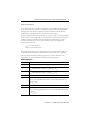
1
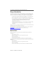
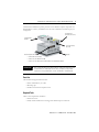
Installation Instructions
PanelView Plus and PanelView Plus Compact
400 and 600 Terminals
Catalog Numbers 2711P-x4xxxx, 2711P-x6xxxx, 2711PC-x4xxxx,
2711PC-x6xxxx
Topic
Page
Important User Information
2
Environment and Enclosure
3
Hazardous Locations
4
Wiring and Safety Guidelines
8
About the Product
8
Parts List
9
Install the Terminal
10
Remove and Install the Power Terminal Block
15
DC Power Connections
16
AC Power Connections
19
Troubleshooting
21
Battery Removal
25
Specifications
26
Additional Resources
28
About This Publication
This document provides instructions on how to install these devices in a panel:
•
•
•
•
PanelView Plus 400 keypad terminal or keypad and touch terminal
PanelView Plus 600 keypad, touch, or keypad and touch terminal
PanelView Plus Compact 400 keypad terminal or keypad and touch terminal
PanelView Plus Compact 600 touch terminal
For complete information on installing, wiring, and troubleshooting the terminals, refer to the
publications listed under Additional Resources.
2
PanelView Plus and PanelView Plus Compact 400 and 600 Terminals
Important User Information
Solid state equipment has operational characteristics differing from those of electromechanical equipment.
Safety Guidelines for the Application, Installation and Maintenance of Solid State Controls (Publication
SGI-1.1 available from your local Rockwell Automation sales office or online at
http://literature.rockwellautomation.com) describes some important differences between solid state
equipment and hard-wired electromechanical devices. Because of this difference, and also because of the
wide variety of uses for solid state equipment, all persons responsible for applying this equipment must
satisfy themselves that each intended application of this equipment is acceptable.
In no event will Rockwell Automation, Inc. be responsible or liable for indirect or consequential damages
resulting from the use or application of this equipment.
The examples and diagrams in this manual are included solely for illustrative purposes. Because of the many
variables and requirements associated with any particular installation, Rockwell Automation, Inc. cannot
assume responsibility or liability for actual use based on the examples and diagrams.
No patent liability is assumed by Rockwell Automation, Inc. with respect to use of information, circuits,
equipment, or software described in this manual.
Reproduction of the contents of this manual, in whole or in part, without written permission of Rockwell
Automation, Inc., is prohibited.
Throughout this manual, when necessary, we use notes to make you aware of safety considerations.
WARNING
IMPORTANT
ATTENTION
Identifies information about practices or circumstances that can cause an explosion in
a hazardous environment, which may lead to personal injury or death, property
damage, or economic loss.
Identifies information that is critical for successful application and understanding of
the product.
Identifies information about practices or circumstances that can lead to personal injury
or death, property damage, or economic loss. Attentions help you identify a hazard,
avoid a hazard and recognize the consequences.
SHOCK HAZARD
Labels may be on or inside the equipment (for example, a drive or motor) to alert
people that dangerous voltage may be present.
BURN HAZARD
Labels may be on or inside the equipment (for example, a drive or motor) to alert
people that surfaces may reach dangerous temperatures.
Publication 2711P-IN002G-EN-P - November 2009
PanelView Plus and PanelView Plus Compact 400 and 600 Terminals
3
Environment and Enclosure
ATTENTION
This equipment is intended for use in a Pollution Degree 2 industrial environment, in
overvoltage Category II applications (as defined in IEC 60664-1), at altitudes up to 2000 m
(6561 ft) without derating.
The terminals are intended for use with programmable logic controllers. Terminals that
are AC powered must also be connected to the secondary of an isolating transformer.
This equipment is considered Group 1, Class A industrial equipment according to
IEC/CISPR 11. Without appropriate precautions, there may be potential difficulties
ensuring electromagnetic compatibility in other environments due to conducted as well
as radiated disturbance.
Korean Radio Wave Suitability Registration - This equipment is registered for
Electromagnetic Conformity Registration as business equipment (A), not home
equipment. Sellers or users are required to take caution in this regard.
This equipment is supplied as open-type equipment. It must be mounted within an
enclosure that is suitably designed for those specific environmental conditions that will
be present and appropriately designed to prevent personal injury resulting from
accessibility to live parts. The interior of the enclosure must be accessible only by the use
of a tool. The terminals meet specified NEMA Type and IEC ratings only when mounted in
a panel or enclosure with the equivalent rating. Subsequent sections of this publication
may contain additional information regarding specific enclosure type ratings that are
required to comply with certain product safety certifications.
In addition to this publication, see:
• Industrial Automation Wiring and Grounding Guidelines, for additional installation
requirements, publication 1770-4.1.
• NEMA Standards publication 250 and IEC publication 60529, as applicable, for
explanations of the degrees of protection provided by different types of enclosure.
ControlNet Communication Ports
ATTENTION
PanelView Plus terminals with ControlNet communications ports include a Network
Applications Port (NAP). This port is for temporarily connecting programming terminals
to devices on a ControlNet network, and are not intended for continuous operation.
Publication 2711P-IN002G-EN-P - November 2009
4
PanelView Plus and PanelView Plus Compact 400 and 600 Terminals
Hazardous Locations
This equipment is suitable for these locations:
•
•
•
•
Class I, Division 2 Groups A, B, C, D
Class II, Division 2 Groups F, G
Class III
Ordinary non-hazardous locations only
The following statement applies to use in hazardous locations.
WARNING
Explosion Hazard
• Substitution of components may impair suitability for hazardous locations.
• Do not disconnect equipment unless power has been switched off and area is
known to be non-hazardous.
• Do not connect or disconnect components unless power has been switched off.
• All wiring must comply with N.E.C. articles 501, 502, 503, and/or C.E.C. section
18-1J2 as appropriate.
• Peripheral equipment must be suitable for the location in which it is used.
The terminals have a temperature code of T4 when operating in a 55 °C (131 °F) maximum
ambient temperature. Do not install the terminals in environments where atmospheric gases
have ignition temperatures less than 135 °C (275 °F).
Publication 2711P-IN002G-EN-P - November 2009
PanelView Plus and PanelView Plus Compact 400 and 600 Terminals
5
Environnements dangereux
Cet équipement ne peut être utilisé que dans les environnements suivants :
•
•
•
•
Classe I, Division 2, Groupes A, B, C, D ;
Classe II, Division 2, Groupes F, G ;
Classe III ;
ou environnements non-dangereux.
La mise en garde suivante s’applique à une utilisation en environnement dangereux.
WARNING
DANGER D’EXPLOSION
• La substitution de composants peut rendre cet équipement impropre à une
utilisation en environnement dangereux.
• Ne pas déconnecter l’équipement sans s’être assuré que l’alimentation est
coupée ou que l’environnement est classé non dangereux.
• Ne pas connecter ou déconnecter des composants sans s’être assuré que
l’alimentation est coupée.
• L’ensemble du câblage doit être conforme, selon le cas, aux articles 501-4(b),
502-4(b) et 503-3(b) du Code national de l’électricité des Etats-Unis.
• L’équipement périphérique doit être adapté à l’environnement dans lequel il
est utilisé.
Le code de température de fonctionnement des terminaux PanelView Plus est T4 pour une
température ambiante maximale de 55 °C. N’installez pas les terminaux dans des
environnements contenant des gaz atmosphériques inflammables à moins de 135 °C.
Publication 2711P-IN002G-EN-P - November 2009
6
PanelView Plus and PanelView Plus Compact 400 and 600 Terminals
USB Ports
The PanelView Plus and PanelView Plus Compact terminals contain a single, universal serial
bus (USB) port that comply with hazardous location environments. This section details the
field wiring compliance requirements and is provided in accordance with the National
Electrical Code, article 500.
400 and 600 Terminals Control Drawing
Associated Nonincendive Field Wiring Apparatus
Nonincendive Field
Wiring Apparatus
PanelView Plus 400/600 Host Product
Nonincendive Field Wiring
USB
Peripheral
Device
USB Port
Table 1 - 400 and 600 USB Port Circuit Parameters
400 and 600
Terminals
Voc
Isc
Ca
La
Groups A and B
Groups C and D
Series A and B 5.25V DC 1.68 A
10 µF
10 µF
15 µH
15 µH
Series C or
later
10 µF
10 µF
3.5 µH
15 µH
5.25V DC 1.68 A
Groups A and B Groups C and D
Selected nonincendive field wiring apparatus must have nonincendive circuit parameters
conforming with Table 2.
Table 2 - Required Circuit Parameters for the USB Peripheral Device
Vmax
≥
Voc
Imax
≥
Isc
Ci + Ccable
≤
Ca
Li + Lcable
≤
La
Publication 2711P-IN002G-EN-P - November 2009
PanelView Plus and PanelView Plus Compact 400 and 600 Terminals
7
Application Information
Per the National Electrical Code the circuit parameters of nonincendive field wiring apparatus
for use in hazardous locations shall be coordinated with the associated nonincendive field
wiring apparatus such that their combination remains nonincendive. The 400 and 600
terminals and the USB peripheral device shall be treated in this manner.
The circuit parameters of the 400 and 600 USB port are given in Table 1. The USB peripheral
device and its associated cabling shall have circuit parameters with the limits given in Table 2
for them to remain nonincendive when used with the 400 and 600 USB port. If cable
capacitance and inductance are not known the following values from ANSI/ISA-RP
12.06.01-2003 may be used:
Ccable = 197 µF/m (60 µF/ft)
Lcable = 0.7 µF/m (0.20 µH/ft)
Nonincendive field wiring must be wired and separated in accordance with 501.10(B)(3) of
the National Electrical Code (NEC) ANSI/NFPA 70 or other local codes as applicable.
This associated nonincendive field wiring apparatus has not been evaluated for use in
combination with another associated nonincendive field wiring apparatus.
Symbol Definitions
Voc
Open circuit voltage of the host USB port.
Isc
Maximum output current of the host USB port.
Vmax
Maximum applied voltage rating of the USB peripheral device.
Vmax shall be greater than or equal to Voc in Table 1 (Vmax ≥ Voc ).
Imax
Maximum current to which the USB peripheral device can be subjected.
Imax shall be greater than or equal to Isc in Table 1 (Imax ≥ Isc).
Ci
Maximum internal capacitance of the USB peripheral device.
Ca
Maximum allowed capacitance of the USB peripheral device and its associated cable. The
sum of Ci of the USB peripheral device and Ccable of the associated cable shall be less
than or equal to Ca
(Ci + Ccable ≤ Ca).
Li
Maximum internal inductance of the USB peripheral device.
La
Maximum allowed inductance of the USB peripheral device and its associated cable. The
sum of Li of the USB peripheral device and Lcable of the associated cable shall be less than
or equal to La
(Li + Lcable ≤ La).
Publication 2711P-IN002G-EN-P - November 2009
8
PanelView Plus and PanelView Plus Compact 400 and 600 Terminals
Wiring and Safety Guidelines
Use publication NFPA 70E, Electrical Safety Requirements for Employee Workplaces, IEC
60364 Electrical Installations in Buildings, or other applicable wiring safety requirements for
the country of installation when wiring the devices. In addition to the NFPA guidelines:
•
•
•
•
connect the device and other similar electronic equipment to its own branch circuit.
protect the input power by a fuse or circuit breaker rated at no more than 15 A.
route incoming power to the device by a separate path from the communication lines.
cross power and communication lines at right angles if they must cross.
Communication lines can be installed in the same conduit as low-level
DC I/O lines (less than 10V).
• shield and ground cables appropriately to avoid electromagnetic interference (EMI).
Grounding minimizes noise from EMI and is a safety measure in electrical
installations.
For more information on grounding recommendations, refer to the National Electrical Code
published by the National Fire Protection Association.
For more information on terminal wiring and grounding applications, refer to publication
2711P-TD001. You can find this publication in the Literature Library at
http://literature.rockwellautomation.com.
About the Product
The base configured unit of the PanelView Plus 400 and 600 terminals includes these
components:
• Power supply, AC or DC
• Display with keypad, touch screen, or keypad and touch screen
• Processor and memory
• RS-232 and USB ports only or
• RS-232, USB, and Ethernet ports with interface for communication module
The fixed configuration of the PanelView Plus Compact 400 and 600 terminals includes these
components:
• Power supply, DC
• Display with keypad, touch screen, or keypad and touch screen
• Processor and memory
• RS-232, USB, and Ethernet ports without interface for communication module
Publication 2711P-IN002G-EN-P - November 2009
PanelView Plus and PanelView Plus Compact 400 and 600 Terminals
9
Communication modules for specific protocols can be ordered as separate components for
field installation or factory assembled to base unit (with communication interface) per your
configuration.
Compact Flash
Card Slot (not shown)
Communication
Module
Power Connection,
AC or DC
Display
Base Configured Unit with:
• USB and RS-232 Ports Only
• USB, RS-232, and Ethernet Ports or
• USB, RS-232, and Ethernet Ports with Interface for Communication Module.
IMPORTANT
When using the DH-485 module, catalog number 2711P-RN3, with PanelView Plus 400
and 600 terminals, the cable length must not exceed 30 m (98 ft) to comply with CE
requirements. For longer cable lengths, use the 1761-NET-AIC or 1747-AIC module.
Parts List
The terminals are shipped with these items:
• Power terminal block, AC or DC
• Mounting clips
• Installation instructions and panel cutout
Required Tools
These tools are required for installation:
• Panel cutout tools
• Small, slotted screwdriver for securing power and RS-232 port connections
Publication 2711P-IN002G-EN-P - November 2009
10
PanelView Plus and PanelView Plus Compact 400 and 600 Terminals
Install the Terminal
Before installing the terminal in a panel, review these topics:
• Mounting clearances
• Panel cutout dimensions
• Product dimensions
Mounting Clearances
Allow adequate clearance around the terminal, inside the enclosure, for adequate ventilation.
Consider heat produced by other devices in the enclosure. The ambient temperature around
the terminals must be between 0…55 °C (32…131 °F).
Minimum clearances for ventilation are:
•
•
•
•
Top clearance: 51 mm (2 in.)
Bottom clearance: 102 mm (4 in.)
Side clearances: 25 mm (1 in.)
Back clearance: 0 mm (0 in.)
Minimum side clearance for insertion of memory card is 102 mm (4 in.).
Panel Cutout Dimensions
Use the full size template shipped with your terminal to mark the cutout dimensions.
Terminal Type
Height, mm (in.)
Width, mm (in.)
400 Keypad or Keypad and Touch
123 (4.86)
156 (6.15)
600 Keypad or Keypad and Touch
142 (5.61)
241 (9.50)
600 Touch
123 (4.86)
156 (6.15)
Mount the Terminal in a Panel
Mounting levers secure the terminal to the panel. The number of levers you use
(4 or 6) varies by terminal type.
ATTENTION
Disconnect all electrical power from the panel before making the panel cutout.
Make sure the area around the panel cutout is clear.
Take precautions so metal cuttings do not enter any components already installed in
the panel.
Failure to follow these instructions may result in personal injury or damage to panel
components.
Publication 2711P-IN002G-EN-P - November 2009
PanelView Plus and PanelView Plus Compact 400 and 600 Terminals
11
Follow these steps to mount the terminal in a panel.
1. Cut an opening in the panel using the panel cutout that shipped with the terminal.
2. If a communication module is ordered separately, attach the module to the base unit
before panel installation.
Refer to the instructions shipped with the module.
3. Make sure the terminal sealing gasket is properly positioned on the terminal.
This gasket forms a compression type seal. Do not use sealing compounds.
Sealing Gasket
4. Install legend strips before installing the terminal if you are using keypad legend strips
on 600 keypad terminals.
Be careful not to pinch legend strip during installation.
5. Place the terminal in the panel cutout.
If you are mounting the terminal in an existing 550 panel cutout, align the terminal
with the center of cutout for adequate gasket sealing.
6. Insert all mounting levers into the mounting slots on the terminal.
Slide each lever until the flat side of lever touches the surface of the panel.
Mounting Slots
Mounting Lever
Flat Side of Lever
Publication 2711P-IN002G-EN-P - November 2009
12
PanelView Plus and PanelView Plus Compact 400 and 600 Terminals
7. When all levers are in place, slide each lever an additional notch or two until you hear
a click.
8. Rotate each lever in the direction indicated until it is in the final latch position.
Follow the latching sequence for the optimum terminal fit.
1
4
4 Levers
Notch
6
3
1
Alignment Marks
Rotate until notch in lever
aligns with proper alignment
mark on terminal.
2
1
5
3
6 Levers
4
2
6
Use the table as a guide to provide an adequate gasket seal between the terminal and
the panel.
Terminal Markings
for Alignment
2 1
6 54 3
ATTENTION
Lever Position
Panel Thickness Range
Typical Gauge
1
1.52…2.01 mm (0.060…0.079 in.)
16
2
2.03…2.64 mm (0.080…0.104 in.)
14
3
2.67…3.15 mm (0.105…0.124 in.)
12
4
3.17…3.66 mm (0.125…0.144 in.)
10
5
3.68…4.16 mm (0.145…0.164 in.)
8/9
6
4.19…4.75 mm (0.165…0.187 in.)
7
Follow the instructions to provide a proper seal and to prevent potential
damage to the terminal. Rockwell Automation assumes no responsibility
for water or chemical damage to the terminal or other equipment within
the enclosure because of improper installation.
Publication 2711P-IN002G-EN-P - November 2009
PanelView Plus and PanelView Plus Compact 400 and 600 Terminals
13
Product Dimensions
The illustrations show approximate product dimensions for the PanelView Plus and
PanelView Plus Compact 400 and 600 terminals. Measurements are in mm (in.).
400 Terminal Dimensions
400 Keypad or
Keypad and Touch
152
(6.0)
185
(7.28)
60
(2.35)
90
(3.54)
71 (2.81)
154 (6.08)
Publication 2711P-IN002G-EN-P - November 2009
14
PanelView Plus and PanelView Plus Compact 400 and 600 Terminals
600 Terminal Dimensions
600 Keypad or
Keypad and Touch
167
(6.58)
266
(10.47)
68
(2.68)
98
(3.86)
71 (2.81)
154 (6.08)
600 Touch
152
(6.0)
185
(7.28)
68 (2.68)
98
(3.86)
71 (2.81)
154 (6.08)
Publication 2711P-IN002G-EN-P - November 2009
PanelView Plus and PanelView Plus Compact 400 and 600 Terminals
15
Remove and Install the Power Terminal Block
The terminals ship with a power block installed. You can remove the power terminal block
for ease of installation, wiring, and maintenance.
WARNING
Explosion Hazard
Substitution of components may impair suitability for hazardous locations.
Do not disconnect equipment unless power has been switched off and area is known to
be non-hazardous.
Do not connect or disconnect components unless power has been switched off.
All wiring must comply with N.E.C. articles 501, 502, 503, and/or C.E.C. section 18-1J2 as
appropriate.
Peripheral equipment must be suitable for the location in which it is used.
ATTENTION
Disconnect all power before installing or replacing components. Failure to disconnect
power may result in electrical shock or damage to the terminal.
Follow these steps to remove the terminal block.
1. Insert the tip of small, flat-blade, screw driver into terminal block access slot.
2. Gently pry terminal block away from terminal to release locking mechanism.
1
Follow these steps to replace the terminal block.
1. Press terminal block base in first with the block leaning outward.
2. Gently push the top of terminal block back to vertical position to snap in locking tab.
2
1
Publication 2711P-IN002G-EN-P - November 2009
16
PanelView Plus and PanelView Plus Compact 400 and 600 Terminals
DC Power Connections
PanelView Plus devices with an integrated, nonisolated, DC power supply have these power
ratings:
• 24V DC nom (18…30V DC)
• 25 W max (1.0 A at 24V DC)
The power supply is internally protected against reverse polarity of the DC+ and DCconnections. Connecting DC+ or DC- source to the functional earth terminal may damage
the device.
The input power terminal block is removable and supports these wire sizes.
Wire Specifications for DC Input Power Terminal Block
Wire Type
Stranded or solid
(1)
Cu 90 °C (194 °F)
Dual-wire Gauge (1)
Single-wire Gauge
Terminal
Screw Torque
0.33…1.31 mm2
(22…16 AWG)
0.33…2.08 mm2
(22…14 AWG)
0.45…0.56 N•m
(4…5 lb•in)
Two-wire maximum per terminal.
The non-isolated power supply does not provide galvanic isolation. A Class 2 Safety
Extra-Low Voltage (SELV) isolated power supply with a 24V DC nominal output voltage is
required to power the terminal.
External Power Supply
Use a single, 24V DC power supply to power each PanelView Plus terminal, such as catalog
number 2711P-RSACDIN. Using a separate, isolated, and ungrounded source to power each
terminal prevents ground loop currents from damaging the terminals.
The output on the power supply must be isolated from the input and not connected to earth
ground.
ATTENTION
Use a Class 2 or SELV power supply as required by local wiring codes for your
installation. These power supplies provide protection so that under normal and
single-fault conditions, the voltage between the conductors, and between conductors
and functional earth or protective earth does not exceed a safe value.
Publication 2711P-IN002G-EN-P - November 2009
PanelView Plus and PanelView Plus Compact 400 and 600 Terminals
17
Functional Earth Connection
PanelView Plus devices with a DC power input have a functional earth terminal that you must
connect to a low-impedance earth ground. The functional earth connection is on the power
input terminal block.
IMPORTANT
The functional earth connection to ground is mandatory. This connection is required for
noise immunity, reliability, and Electromagnetic Compliance (EMC) with the European
Union (EU) EMC directive for CE-mark conformance.
The functional earth terminal wiring requires a minimum wire gauge.
Functional Earth Wire Specifications for DC Power
Wire Type
Stranded or solid
Cu 90 °C (194 °F)
Wire Gauge
Terminal Screw Torque
2.08... 3.31 mm2
(14…12 AWG)
0.45…0.56 N•m (4…5 lb•in)
On most PanelView Plus devices, the functional earth terminal is internally connected to the
DC- terminal within the product.
ATTENTION
Damage or malfunction can occur when a voltage potential exists between two separate
ground points. Make sure the terminal does not serve as a conductive path between
ground points at different potentials.
The PanelView Plus devices have isolated and nonisolated communication ports.
For more information on wiring and grounding, refer to publication 2711P-TD001 available
at http://www.literature.rockwellautomation.com.
Publication 2711P-IN002G-EN-P - November 2009
18
PanelView Plus and PanelView Plus Compact 400 and 600 Terminals
Connect DC Power
WARNING
Explosion Hazard - Do not disconnect equipment unless power has been switched off and
area is known to be nonhazardous.
Disconnect all power before installing or replacing components. Failure to disconnect
power may result in electrical shock and/or damage to the terminal.
Follow these steps to connect DC power.
1. Disconnect power to the terminal.
2. Secure the DC power wires to the terminal block screws.
Follow the markings on terminal blocks and terminal for proper connections.
3. Secure the functional earth ground wire to the functional earth ground terminal screw
on the input power terminal block.
DC+
DC-
Functional
Earth Ground
to Ground Bus
4. Apply 24V DC power to the terminal.
Publication 2711P-IN002G-EN-P - November 2009
PanelView Plus and PanelView Plus Compact 400 and 600 Terminals
19
AC Power Connections
The 400 to 600 terminals with an integrated AC power supply have these power ratings:
• 85…264V AC (47…63 Hz)
• 60V A maximum
The input power terminal block is removable and supports these wire sizes.
Wire Specifications for AC Input Power Terminal Block
Wire Type
Stranded or solid
(1)
Cu 90 °C (194 °F)
Dual-wire Gauge (1)
Single-wire Gauge
Terminal Screw
Torque
0.33…1.31 mm2
22…16 AWG
0.33…2.08 mm2
22…14 AWG
0.45 …0.56 N•m
(4…5 lb•in)
Two-wire max. per terminal.
Protective Earth Connection
PanelView Plus AC terminals have a protective earth ground terminal that you must connect
to a low-impedance earth ground.
ATTENTION
The protective earth connection is required for both electrical safety and Electromagnetic
Compliance (EMC) with the EU (European Union) EMC directive for CE-mark conformance.
The terminals have the protective earth ground connection on the power input terminal
block. The protective earth terminal wiring requires a minimum wire gauge.
Protective Earth Wire Specifications for AC Power
Wire Type
Stranded or solid
Cu 90 °C (194 °F)
Wire Gauge
Terminal Screw Torque
2.08…3.31 mm2
(14…12 AWG)
0.45…0.56 N•m (4…5 lb•in)
Publication 2711P-IN002G-EN-P - November 2009
20
PanelView Plus and PanelView Plus Compact 400 and 600 Terminals
Connect AC Power
WARNING
Explosion Hazard - Do not disconnect equipment unless power has been switched off and
area is known to be nonhazardous.
Disconnect all power before installing or replacing components. Failure to disconnect
power may result in electrical shock and/or damage to the terminal.
ATTENTION
Improper wiring of power terminals may result in voltage at the communication
connector shells. Refer to the following figure when wiring.
Do not apply power to the terminal until all wiring connections have been made. Failure
to do so may result in electrical shock.
Follow these steps to connect AC power.
1. Disconnect power from the terminal.
2. Secure the AC power wires to the terminal block screws.
3. Secure the protective earth ground wire to the protective earth ground terminal screw
on the input terminal block.
L1
L2/Neutral
Protective Earth
to Ground Bus
4. Apply AC power to the terminal.
Publication 2711P-IN002G-EN-P - November 2009
PanelView Plus and PanelView Plus Compact 400 and 600 Terminals
21
Troubleshooting
If the terminal is not operating correctly, check the power, display settings, status indicators,
and review the system startup and error messages.
Check for Adequate Power
A terminal that does not receive adequate power could cause unpredictable behavior. Verify
the power requirements in the Specifications table.
Check the Status Indicators
The terminal has two status indicators to isolate operating problems.
• COMM indicator (green) for communications
• FAULT indicator (red) for hardware faults
COMM and Fault
Indicators
When the terminal starts up, the fault indicator should be off, except for a few brief flashes,
and the comm indicator on. If the indicators remain off, check the power cable.
After a successful startup, both indicators are off and controlled by the application running
on the terminal.
Publication 2711P-IN002G-EN-P - November 2009
22
PanelView Plus and PanelView Plus Compact 400 and 600 Terminals
The table shows indicator states if the terminal powers on and stops during startup.
Indicator States If the Terminal Stops During Startup
Fault (Red)
Indicator
Blinking(1)
On(2)
Comm (Green)
Indicator
Description
Off
Last firmware download failed.
Reload firmware using Firmware Upgrade Wizard (FUW) utility.
Blinking
EBC boot loader firmware failed or is missing.
Reload firmware using Firmware Upgrade Wizard (FUW) utility.
On
Windows CE OS firmware failed or is missing.
Reload firmware using Firmware Upgrade Wizard (FUW) utility.
Off
Fatal hardware error occurred.
Replace the terminal.
Blinking
Fatal hardware error in display.
Replace the terminal.
(1)
Blinking red indicates a recoverable error.
(2)
Solid red indicates a nonrecoverable or fatal error.
Publication 2711P-IN002G-EN-P - November 2009
PanelView Plus and PanelView Plus Compact 400 and 600 Terminals
23
Check the Display
If the terminal display is dim or unreadable:
• check the brightness setting. From terminal Configuration mode, choose Terminal
Settings>Display Intensity.
• check the contrast setting. From terminal Configuration mode, choose Terminal
Settings>Display Contrast.
• check the Screen Saver settings. The backlight may turn off or dim the display
unexpectedly. From terminal Configuration mode, choose Terminal
Settings>Display>Screen Saver.
Startup Information Messages
Startup information messages display in a specific sequence on the terminal screen during
startup and typically display for a few seconds. These messages do not require that you
perform any action.
Message #
Message
Description
30
Watchdog Test
Tests the watchdog circuitry to verify system integrity.
1
RAM Test
Tests the RAM memory.
2
Image Search
Checks for new OS firmware upgrade on the external compact flash
card and the serial port.
11
Downloading Image
Transfers a new OS firmware upgrade to internal RAM. Message may
remain on screen for several minutes.
20
Transfer Image
Programs the OS firmware just downloaded into RAM. Message may
remain on screen for several minutes.
24
CRC Check
Checks the integrity of the OS firmware.
27
Decompress System
Decompresses the compressed OS firmware into RAM.
28
Starting System
Launches the operating system (OS).
29
System Check ###
Internal file system integrity check (### is percent progress indicator).
29.1
System Check
Internal file system check disabled. Contact technical support.
Publication 2711P-IN002G-EN-P - November 2009
24
PanelView Plus and PanelView Plus Compact 400 and 600 Terminals
Startup Error Messages
When an error occurs, the terminal displays an error number with a text message. The word
ERROR! appears under the message in different languages.
# Displayed Message
ERROR! FEHLER! ERREUR! ERRORE!
Error #
Message
Description
Recommended Corrective Action
1
RAM Test
RAM test failure.
Reset the terminal. If error persists, replace the
terminal.
14
RAM Header
Check
OS firmware that is
downloading is not
compatible with
hardware.
Check that you are using the correct version and type
of firmware upgrade. Reset the terminal and upgrade
with the correct firmware version.
20
Transfer Image
Programming the
downloaded OS
firmware into Flash
failed.
Reset the terminal and attempt the firmware upgrade
again. If error persists, replace the terminal.
23
Download Task
OS firmware that is
downloading to the
terminal is too large.
Check that you are using the correct version and type
of firmware upgrade. Reset the terminal and upgrade
with the correct firmware version.
24
CRC Check
Checksum of the OS
firmware failed.
Reload the firmware. If error persists, replace the
terminal.
25
Invalid Prod
Family
OS firmware that is
downloading is not
compatible with
terminal.
Check that you are using the correct version and type
of firmware upgrade. Reset the terminal and upgrade
with the correct firmware version.
27
Decompress
System
Error decompressing
the OS firmware from
flash to RAM.
Reload the firmware. If error persists, replace the
terminal.
30
Watchdog Test
Watchdog test
failure.
Reload the firmware. If error persists, replace the
terminal.
31
Stuck Key
Function key failure.
Check that nothing is pressed against a key. Reset
the terminal without key presses. If error persists,
replace the terminal.
3a
Stuck Touch
Touch screen failure.
Check that nothing is pressed against the touch
screen. Reset the terminal without touch screen
presses. If error persists, replace the terminal.
40
EXE Check
System OS firmware
is missing or corrupt.
Reload the firmware. If error persists, replace the
terminal.
Publication 2711P-IN002G-EN-P - November 2009
PanelView Plus and PanelView Plus Compact 400 and 600 Terminals
25
Battery Removal
The 400 and 600 terminals contain a lithium battery that is permanently connected and
should be removed only by trained professionals.
This product contains a hermetically sealed lithium battery which may need to be
replaced during the life of the product.
At the end of its life, the battery contained in this product should be collected separately
from any unsorted municipal waste.
The collectioin and recyling of batteries helps protect the environment and contributes to
the conservation of natural resources as valuable materials are recovered.
Follow these steps to remove the battery on the 400 and 600 terminals.
1. Disconnect power from the terminal.
2. Place the terminal, display side down, on a flat stable surface.
3. Detach the communication module, if attached, from the logic module by removing
the three screws.
4. Unlatch the eight retaining tabs (two on each side) on the back cover and remove
cover.
5. Locate the yellow battery on the logic board.
6. Remove the battery.
Retaining tabs
Battery
Publication 2711P-IN002G-EN-P - November 2009
26
PanelView Plus and PanelView Plus Compact 400 and 600 Terminals
Specifications
PanelView Plus and PanelView Plus Compact 400 and 600 Terminals
Attribute
Value
Display
400 and 600 grayscale display
400 and 600 color display
Grayscale passive matrix, film compensated super-twist nematic
(FSTN) LCD technology
Color active matrix, thin film transistor (TFT) LCD technology
Display size, Approx., diagonal
400 grayscale display
400 color display
600 grayscale/color display
95 mm (3.7 in.)
89 mm (3.5 in.)
139 mm (5.5 in.)
Display area (WxH), Approx.
400 grayscale display
400 color display
600 grayscale/color display
77 x 58 mm (3.0 x 2.3 in.)
71 x 53 mm (2.8 x 2.1 in.)
112 x 84 mm (4.4 x 3.3 in.)
Display resolution
400 grayscale/color display
600 grayscale/color display
320 x 240
320 x 240
Backlight
400 grayscale/color display
600 grayscale/color display
LED
CCFL 50,000 hours life, min.
Touch Screen
Touch screen
Analog resistive
Actuating rating
1 million presses
Operating force
10…110 g
Keypad
Function keys
8 or 10 function, numeric and navigation keys
Actuation rating
1 million presses
Operating force
340 g
Electrical
Input voltage, DC
Power consumption, DC
24V DC nom (18… 30V DC)
25 W max (1.0 A @ 24V DC)
Input voltage, AC
Power consumption, AC
85…264V AC, 47…63 Hz
60V A max
Publication 2711P-IN002G-EN-P - November 2009
PanelView Plus and PanelView Plus Compact 400 and 600 Terminals
27
PanelView Plus and PanelView Plus Compact 400 and 600 Terminals
Dimensions (HxWxD), approx.
400 keypad, or keypad and touch
152 x 185 x 90 mm (6.0 x 7.28 x 3.54 in.)
600 keypad, or keypad and touch
167 x 266 x 98 mm (6.58 x 10.47 x 3.86 in.)
600 touch
152 x 185 x 98 mm (6.0 x 7.28 x 3.86 in.)
Weight, approx.
400 keypad (1), or keypad and touch
635 g (1.40 lb)
600 keypad, or keypad and touch (1)
930 g (2.05 lb)
600 touch (1)
789 g (1.74 lb)
General
Battery life
5 year min at 77 °F (25 °C)
Clock
Battery backup, + /- 2 minutes per month
Status indicators
COMM (Green), Fault (Red)
Application flash memory
20 MB
External compact flash storage
512 MB max
(1)
Add approximately 95 g (0.21 lb) for communication module.
Environmental Specifications
Attribute
Value
Temperature, operating
0…55 °C (32…131 °F)
Temperature, storage
-25…70 °C (-13…158 °F)
Heat dissipation
80 BTU/hr
Altitude, operating
2000 m (6561 ft)
Vibration
10… 57 Hz, 0.012 pk-pk displacement
57…500 Hz 2.0 g pk acceleration
Shock, operating
15 g at 11 ms
Shock, nonoperating
30 g at 11 ms
Relative humidity
5…95% without condensation
Enclosure ratings
NEMA Type 12, 13, 4X (indoor use only), IP54, IP65
Publication 2711P-IN002G-EN-P - November 2009
28
PanelView Plus and PanelView Plus Compact 400 and 600 Terminals
Certifications(1)
Certification
c-UL-us
UL Listed Industrial Control Equipment, certified for US and Canada. See
UL File E10314.
UL Listed Industrial Control Equipment for use in:
• Class I, Div 2, Group A, B, C, D
• Class II, Div 2 Groups F, G
• Class III Hazardous Locations
CE (EMC)
European Union 2004/108/EC EMC Directive, compliant with:
EN 61000-6-2; Industrial Immunity
EN 61000-6-4; Industrial Emissions
CE (LVD)
European Union 2006/95/EC Low Voltage Directive, compliant with:
EN 61131-2; Programmable Controllers
C-Tick
Australian Radiocommunications Act, compliant with:
AS/NZS CISPR 11; Industrial Emissions
(1)
See the Product Certification link on http://www.ab.com for declarations of conformity, certificates, and other certification
details.
Additional Resources
For additional information on these products, refer to these publications.
Resource
Description
PanelView Plus User Manual,
publication 2711P-UM001
Provides an overview of the PanelView Plus and PanelView
Plus CE terminals and gives information on how to install,
operate, configure, and troubleshoot these devices.
Wiring and Grounding Applications for
PanelView Plus devices Technical Data,
publication 2711P-TD001
Provides additional information on wiring and grounding the
PanelView Plus and PanelView Plus CE terminals.
You can view or download publications and translated versions of the installation instructions
at http://literature.rockwellautomation.com. To order paper copies of technical
documentation, contact your local Rockwell Automation distributor or sales representative.
Publication 2711P-IN002G-EN-P - November 2009
PanelView Plus and PanelView Plus Compact 400 and 600 Terminals
29
Publication 2711P-IN002G-EN-P - November 2009
30
PanelView Plus and PanelView Plus Compact 400 and 600 Terminals
Publication 2711P-IN002G-EN-P - November 2009
PanelView Plus and PanelView Plus Compact 400 and 600 Terminals
31
Publication 2711P-IN002G-EN-P - November 2009
Rockwell Automation Support
Rockwell Automation provides technical information on the Web to assist you in using its
products. At http://support.rockwellautomation.com, you can find technical manuals, a
knowledge base of FAQs, technical and application notes, sample code and links to software
service packs, and a MySupport feature that you can customize to make the best use of these
tools.
For an additional level of technical phone support for installation, configuration and
troubleshooting, we offer TechConnect support programs. For more information, contact
your local distributor or Rockwell Automation representative, or visit
http://support.rockwellautomation.com.
Installation Assistance
If you experience a problem within the first 24 hours of installation, please review the
information that's contained in this manual. You can also contact a special Customer Support
number for initial help in getting your product up and running.
United States
1.440.646.3434
Monday – Friday, 8 a.m. – 5 p.m. EST
Outside United
States
Please contact your local Rockwell Automation representative for any
technical support issues.
New Product Satisfaction Return
Rockwell Automation tests all of its products to ensure that they are fully operational when
shipped from the manufacturing facility. However, if your product is not functioning and
needs to be returned, follow these procedures.
United States
Contact your distributor. You must provide a Customer Support case number
(see phone number above to obtain one) to your distributor in order to
complete the return process.
Outside United
States
Please contact your local Rockwell Automation representative for the return
procedure.
Allen-Bradley, Rockwell Automation, and TechConnect are trademarks of Rockwell Automation, Inc.
Trademarks not belonging to Rockwell Automation are property of their respective companies.
Publication 2711P-IN002G-EN-P - November 2009
Supersedes Publication 2711P-IN002F-EN-P - March 2009
Copyright © 2009 Rockwell Automation, Inc. All rights reserved.Printed in the U.S.A.