1
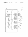
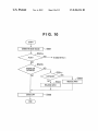
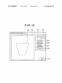
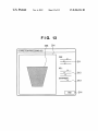
US008306324B2
(12) Ulllted States Patent
(10) Patent N0.:
Sanami
(54)
(45) Date of Patent:
Nov. 6, 2012
IMAGE PROCESSING METHOD AND IMAGE
5,680,525 A *
PROCESSING APPARATUS
5,949,431 A
6,201,548 B1
9/1999 Matsumura et al.
3/2001 Cariffe et al.
6,345,117
2/2002
.
(75)
US 8,306,324 B2
Inventor:
.
.
.
Hlroyukl sanamls Kawasakl (JP)
10/1997 Sakai et a1. ................. .. 345/585
B2 *
6,839,086 B1 *
_
7,340,097 B2
(73) Ass1gnee: Canon Kabushiki Kaisha, Tokyo (JP)
7,831,095 B2
2004/0227772 A1
( * ) Notice:
Subject to any disclaimer, the term of this
patent is extended or adjusted under 35
U'S'C' 154(1)) by 0 days‘
(21)
Appl. N0.: 13/216,399
(22)
Filed:
_
Aug. 24, 2011
(65)
...................... .. 382/167
3/2008 Kondo et al.
11/2010 Sanami
ll/2004 Huang et al.
l
$015119 et a1t~ l
.0 ojlmae a‘
2006/0115185 A1
6/2006 llda et al.
FOREIGN PATENT DOCUMENTS
JP
59433665 A
@1984
JP
04-340671 A
ll/l992
JP
05-061970 A
3/1993
Prior Publication Data
Us 2011/0304637 A1
Klassen
1/2005 Katagiri ,,,,,,,,,,,,,,,,,,,,,, ,, 348/347
OTHER PUBLICATIONS
Dec_ 15’ 2011
Japanese Of?ceActionissuedonJul. 2, 2012,inc0unterpartJapanese
application No. 2011-162449.
(63)
Related US. Application Data
Continuation of application No. 11/ 675,333, ?led on
* Cited by examiner
Feb. 15, 2007, noW Pat. No. 8,027,535.
Primary Examiner * lshrat 1 Sherali
_
(30)
_
_
(74) AZZ0rney,Agenl, orFirm *FitZpatrick,Cella,Harper&
Scimo
(JP) ............................... .. 2006-048979
Int, C],
(57)
ABSTRACT
This invention relates to an image processing method and
G06K 9/34
(52)
(58)
_
Foreign Application Priority Data
Feb. 24, 2006
(51)
_
(2006.01)
image processing apparatus for improving the image quality
US. Cl. ...................................... .. 382/173; 382/199
Field of Classi?cation Search ................ .. 382/162,
of the boundary pan of an image cut-out or deletion area.
According to this method, an area Speci?ed by a user as 21
382/167, 173, 282a283, 199; 358/19, 537a540,
358/452i453; 345/418, 585, 62(L622, 6334635;
cut-out or deletion target area is slightly reduced or enlarged
to eliminate an undesirable background area. In image cut
348/347; 7l5/724i725, 764, 768, 770
See application ?le for complete search history.
out, the cut-out image side is shaded off. In image deletion,
the background image side is shaded off. This increases the
image quality at the joint betWeen the boundary part of the
cut-out image and an image to be composited. The image
(56)
References Cited
quality betWeen the remaining background image and the
us PATENT DOCUMENTS
4,949,279
5,613,046 A *
deletion part also improves.
3/
8/1990
1997 Dermer
Takakura..........
et a1. ..
GENERATE MASK IMAGE
6 Claims, 13 Drawing Sheets
1» S501
$504
I
|
SHADE OFF
1
(E)
F S505
ENLARGE AREA
US. Patent
Nov. 6, 2012
Sheet 1 0f 13
US 8,306,324 B2
8K
.6:
A
Q21
:TAH
MW21
V“EEO EZ
N
a$1
V
Av
¢
mg.no?
US. Patent
CUTOUT
Nov. 6, 2012
Sheet 2 0f 13
US 8,306,324 B2
201
208
203
204
I
/
l
/
/
/
ADD
DELETE
\
/
/
\
\
POLYGON q/ 205
FREEHAND K/ 206
COLOR
SELECTION “" 207
E] SHADE OFF /\/ 202
US. Patent
CUTOUT
Nov. 6, 2012
Sheet 3 0f 13
US 8,306,324 B2
201
302
203
204
l
/
l
(
/
/
ADD
DELETE
\
\
/
/
\
POLYGON /\/205
FREEHAND I\/ 206
coma
SELECTION ’_\" 207
R
30.1
[:1 SHADE OFF ?/ 202
US. Patent
Nov. 6, 2012
Sheet 4 0f 13
US 8,306,324 B2
F I G- 4
CUTOUT
2§1 4/01
2g3 25:4
\\\\\\v
éi goé gzé
US. Patent
Nov. 6, 2012
Sheet 5 0f 13
US 8,306,324 B2
FIG. 5
I START I
v
GENERATE MASK IMAGE
ADDITION MODE?
"\1 S501
No
v
/
ENLARGE AREA
REDUCE AFIEA
II
SHADE OFF
II
END
'
N S505
/ S504
US. Patent
Nov. 6, 2012
Sheet 6 0f 13
US 8,306,324 B2
F l G. 6A
BRIGH‘TNESS
-'
INSIDE OF MASK IMAGE
MASK IMAGE BOUNDARY
4—
> PIXEL
F I G. 68
BRIGHTNESS
A
MASK IMAGE BOUNDARY
P PIXEL
2 PIXELS
US. Patent
Nov. 6, 2012
Sheet 7 0f 13
US 8,306,324 B2
FIG. 7
201
C UTOUT
203
204
“T “\
/
/
ADD
DELETE
POLYGON ’\-/ 205
FREEHAND
/ 206
COLOR
SELECTION ’\" 207
[I] SHADE OFF "v 202
DETAIL
SETUP
K" 209
US. Patent
Nov. 6, 2012
Sheet 8 0f 13
US 8,306,324 B2
FIG. 8
DETAIL SETUP
O INWARD w 801
O OUTWARD w 802
O CENTER »» 803
@ AUTO Av 804
OK
CANCEL
(
K
806
805
US. Patent
Nov. 6, 2012
Sheet 9 0f 13
US 8,306,324 B2
F I G. 9A
901
BRIGHTNESS
‘
MASK IMAGE BOUNDARY
>P|XEL
F | G. 9B
BRIGHTNESS
902
A
255
'
f
I \ MASK IMAGE BOUNDARY
' \ 903
0
5
905)
k
904
>PIXEL
US. Patent
Nov. 6, 2012
Sheet 10 0f 13
US 8,306,324 B2
( START )
V
GENERATE MASK IMAGE
~ 8501
TO S502 IN FIG. 5
INWARD OR
OUTWARD?
N0
/ S504
ENLARGE AREA
:
v
V
SHADE OFF
END
~ S505
REDUCE AREA
US. Patent
Nov. 6, 2012
Sheet 11 0f 13
US 8,306,324 B2
FIG. 11
( START I
Y
/s1101
~S1100
SET AREA
T
/s1102
GENERATE MASK IMAGE
Y
/S1201
SELECT CORRECTION PROCESSING
T
/s1202
CORRECTION PROCESSING
@
w S1200
US. Patent
Nov. 6, 2012
Sheet 12 0f 13
US 8,306,324 B2
FIG. 12
208
201
203
204
/
/
ADD
DELETE
/
CORRECTION PROCESSING (1/2) /
/
POLYGON "\~/ 205
FREEHAND /\/ 206
COLOR
SELECTION ’\" 207
[I SHADE OFF ” / / 202
NEXT
'v 210
U S Patent
N V. 6, 2012
US 8,306,324 B2
Sheet 13 0f 13
FIG. 13
CORRECTION PROCESSING (212)
SHARPNESS I
END
V214
US 8,306,324 B2
1
2
IMAGE PROCESSING METHOD AND IMAGE
PROCESSING APPARATUS
According to one aspect of the present invention, prefer
ably, there is provided an image processing method of cutting
out or deleting a target desired by a user from an image
displayed in a display window, comprising: a displaying step
RELATED APPLICATIONS
of displaying, in the display window, an image to be cut out or
deleted; a specifying step of specifying a boundary of an area
of the cut-out or deletion target from the image displayed in
This is a continuation of application Ser. No. 11/675,333,
?led Feb. 15, 2007, claims bene?t of that application under 35
U.S.C. §120, and claims bene?t under 35 U.S.C. §119 of
Japanese Patent Application No. 2006-048979, ?led Feb. 24,
to reduce or enlarge, by a small amount, a closed area de?ned
2006. The entire contents of each of the two mentioned prior
by the boundary speci?ed in the specifying step; and an
the displaying step; an altering step of altering the boundary
applications are incorporated herein by reference.
editing step of editing to cut out or delete an image in the
closed area de?ned by the boundary altered in the altering
BACKGROUND OF THE INVENTION
step.
According to another aspect of the present invention, pref
1. Field of the Invention
The present invention relates to an image processing
erably, there is provided a computer program which executes
each step recited in the above method in a computer.
method and image processing apparatus. Particularly, the
According to still another aspect of the present invention,
preferably, there is provided an image processing apparatus
present invention relates to an image processing method and
image processing apparatus which man-machine-interac
20
tively select a partial area of an image displayed on a screen
and cut out or process the image in the selected area.
2. Description of the Related Art
computer program; instruction means for causing a user to
In cutting out a part of an image displayed on a screen and
compo siting it with another image, a known technique is used
input an instruction to the image processing apparatus; and
25
to shade off the edge of the cut-out area to suppress jagged
ness of the image edge. For example, Japanese Patent Publi
cation Laid-Open No. 4-340671 proposes a technique of sup
30
is noticeable.
As a psychological aspect of an operator who should
specify an image cut-out area man-machine-interactively,
she/he tends to set an area including the cut-out target image
as much as possible. As a result, the cut-out boundary part
often contains the background image. If the periphery of the
boundary part shades off in this state, the background image
BRIEF DESCRIPTION OF THE DRAWINGS
35
40
according to a typical embodiment of the present invention;
FIG. 2 is a view showing an example of the display window
of an application executed by the personal computer shown in
FIG. 1;
FIG. 3 is a view showing a state wherein a user repeatedly
clicks on outline points of a displayed image;
45
FIG. 4 is a view showing a display window after cut-out
area determination;
FIG. 5 is a ?owchart showing shade-off processing accord
area extends, resulting in a poor image quality in the bound
ing to the ?rst embodiment;
FIGS. 6A and 6B are graphs showing changes in the bright
ness value of the edge (boundary) part of a mask image
If an area is partially deleted from an image with shading
50
obtained by shade-off processing;
FIG. 7 is a view showing an example of a window dis
played on a display screen by an application that executes
image processing according to the second embodiment;
Additionally, the operator feels stress in editing and ?nely
adjusting the boundary part of an image cut-out area by, e. g.,
man-machine-interactively editing the outline point of each
pixel or painting the mask edge.
FIG. 1 is a block diagram showing the arrangement of a
personal computer that performs an image processing method
ary area.
off near the edge, the contrast of the edge part is degraded.
The edge of the deletion target area that must be transparent
becomes translucent. Hence, it is impossible to completely
delete the desired part.
apparent from the following description of exemplary
embodiments with reference to the attached drawings.
suppression of jaggedness.
In the prior art, however, background pixels around the
boundary are subjected to shade-off processing upon shading
off the edge periphery. This processing may make transparent
background pixels translucent. As a result, the processed part
input means for inputting image data representing the image.
The invention is particularly advantageous since it enables
high-quality image cut-out and image deletion by excluding
any undesirable image other than the selection target.
Further features of the present invention will become
pressing jaggedness upon image composition by shading off
both sides of the boundary of a mask image (by uniformly
allocating the shade-off inside and outside of the image).
The technique of shading off the boundary part of a mask
image in cut-out image composition is very effective for
which executes the above computer program, comprising: a
display which displays an image; a storage device in which
the computer program is installed; a CPU which executes the
55
SUMMARY OF THE INVENTION
FIG. 8 is a view showing a detail setup dialogue display
window that is displayed by clicking on a detail setup button;
FIGS. 9A and 9B are graphs showing changes in the bright
ness value of the edge (boundary) part of a mask image
obtained by shade-off processing according to the second
embodiment;
Accordingly, the present invention is conceived as a
response to the above-described disadvantages of the conven
tional art.
For example, an image processing method and an appara
60
FIG. 10 is a ?owchart showing shade-off processing
according to the second embodiment;
FIG. 11 is a ?owchart showing shade-off processing
according to the third embodiment;
65
delete an image; and
tus using the method according to this invention are capable
of improving the image quality in image cut-out composition
processing by selectively de?ning the way of shading off a
mask image.
FIG. 12 is a view showing a display window to cut out or
FIG. 13 is a view showing a display window to set correc
tion parameters.
US 8,306,324 B2
3
4
DESCRIPTION OF THE EMBODIMENTS
FIRST EMBODIMENT
be described in detail in accordance With the accompanying
FIG. 2 is a vieW shoWing an example of a WindoW dis
played on a display screen by an application that executes
drawings.
image processing according to the ?rst embodiment. As
Preferred embodiments of the present invention Will noW
shoWn in FIG. 2, When the user initiates to execute the appli
cation, an image 208 to be cut out is displayed in a display
WindoW 201.
Referring to FIG. 2, reference numeral 202 denotes a check
box to instruct the PC to shade off the boundary of the image;
203, an “add” tab; and 204, a “delete” tab. Addition process
FIG. 1 is a block diagram shoWing the arrangement of a
personal computer (PC) that performs image cut-out process
ing according to a typical embodiment of the present inven
tion.
Any information processing apparatus other than the PC
shoWn in FIG. 1 can perform the image cut-out processing
according to this embodiment if it fundamentally has the
ing and deletion processing indicated by these tabs are exclu
sively performed each other so that one of them is alWays
same arrangement as the PC. In addition to a stand-alone PC,
a plurality of computers connected via a netWork to distribute
functions or a portable computer is usable.
As shoWn in FIG. 1, a PC 100 is connected to an image
input device 101 that reads an image as digital data, and a
keyboard 102 and mouse 103 provided to man-machine-in
teractively perform image cut-out processing. A user can
input an instruction of, e.g., image processing or WindoW
manipulation to the PC 100 by using the keyboard 102 and
active. Tool buttons 205 to 207 are used to select a Way of
setting a cut-out or deletion area. The three buttons have an
exclusive relationship betWeen them so that one of them is
alWays displayed in the selection WindoW With a gray back
ground.
Although not illustrated, When the “delete” tab 204 is
20
mouse 103. The PC 100 is also connected to a display 105
such as an LCD that displays various kinds of information and
images. The display 105 may be of an integrated type that is
incorporated in the main body of the PC 100.
25
selected area is displayed transparent.
The image input device 101 includes at least one of a DVD
Upon activating the application, the “add” tab is active, as
drive, CD drive, scanner, digital camera, PC card, ?exible
disk, magneto-optical (MO) disk drive, ZIP drive®, and ?le
system. The image input device 101 is connected to the PC
100 via a peripheral device interface (UP) 110.
30
shoWn in FIG. 2.
The tool button 205 is an instruction button (polygon but
ton) to add a polygonal graphic pattern. After clicking on this
button, the user sets outline points by clicking in the Window.
Not only the image input device but also a printer (not
The user ?nally double-clicks to ?ll in the area de?ned by the
shoWn) can also be connected to the peripheral device inter
face (I/F). The printer receives image data and prints an
image. In this embodiment, a USB is employed as the periph
active, the check box 202 and tool buttons 205 to 207 are
displayed in the operation WindoW of this tab so that the user
can perform the same operation as in addition processing.
The user adds an image cut-out area by making the “add”
tab active and setting a cut-out area. On the other hand, the
user deletes an image cut-out area by making the “delete” tab
active and setting a deletion area. In the deletion mode, the
outline points.
eral device interface. HoWever, an interface conforming to
The tool button 206 is a button (freehand) to add a cut-out
area freehand. After clicking on this button, the user drags the
another speci?cation is also usable.
cursor displayed in the WindoW to select an area.
The PC 100 includes a CPU 106 that controls the overall
functions, a ROM 107 that stores programs and parameters
requiring no change, a RAM 108 that temporarily stores
programs and data supplied from an external device, and an
The tool button 207 is a color selection button. After click
ing on this button, the user clicks in the WindoW to ?ll in a
color area similar to the clicked point.
FIG. 3 is a vieW shoWing a state Wherein the user repeatedly
clicks on outline points of a displayed image. The same ref
erence numerals as already described in FIG. 2 denote the
same constituent elements in FIG. 3, and a description thereof
Will be omitted.
Referring to FIG. 3, reference numeral 301 denotes a cur
sor; and 302, a selected path. FIG. 3 shoWs a state Wherein the
35
40
external storage device 109. The external storage device 109
may be a ?xed medium such as a hard disk or a nonvolatile
memory card With a mass storage volume. The external stor
age device 109 may also be a removable medium such as a
45
?exible disk (FD) or a compact disk (CD). Other examples of
the removable medium may be a magnetic card, optical card,
IC card, and memory card.
user is setting the path 302 along the edge of the image 208.
The PC 100 comprises an operation input interface (UP)
104 to connect the keyboard 102 and mouse 103, and a dis
At the end of operation, the user double-clicks the mouse 103
50
play UP 111 to connect the display 105. The PC 100 also
area or deletion area.
FIG. 4 is a vieW shoWing a display WindoW after cut-out
comprises a netWork UP 113 to connect to Internet 112. The
PC 100 can also be connected to a LAN or another netWork
via the netWork UP 113.
These constituent elements are connected to each other via
that drags the cursor 301, thereby determining the cut-out
area determination.
55
As shoWn in FIG. 4, When the cut-out area is determined, a
selected area 401 is ?lled in With black. Note that the ?lled
a system bus 114.
area 401 is shoWn as a shaded area in FIG. 4.
The RAM 108 temporarily saves image data, image infor
mation, and calculation results during the operation.
Not only an operating system (OS) to operate the PC 100
If the application is ended in this state, the selected area 401
is set as a mask image. The RAM 108 holds the mask image
but also a printer driver to operate a printer and an application
program (to be referred to as an application hereinafter) to
execute image cut-out processing to be described beloW are
installed in the external storage device 109.
as the transparency information of the original image.
60
executed.
FIG. 5 is a ?owchart shoWing shade-off processing accord
ing to the ?rst embodiment.
Some embodiments of image processing executed by the
PC With the above-described arrangement Will be described
next. This image processing is executed When the user acti
vates the application.
If the user turns on the check box 202 and generates a mask
image by setting outline points, shade-off processing is
65
In step S501, a mask image Without shading is generated.
This is performed by causing the user to execute the above
described operation shoWn in FIGS. 2 to 4.
US 8,306,324 B2
5
6
In step S502, it is checked Whether or not the current mode
is the addition mode. If the current mode is the addition mode
FIG. 7 is a vieW shoWing an example of a WindoW dis
played on a display screen by an application that executes
(the “add” tab 203 is selected in the display WindoWs shoWn
image processing according to the second embodiment. The
in FIGS. 2 to 4), the process advances to step S503 to reduce
same reference numerals as already described in the ?rst
embodiment denote the same constituent elements in FIG. 7,
and a description thereof Will be omitted.
Referring to FIG. 7, reference numeral 209 denotes a detail
the mask image area by tWo pixels, thereby reducing the mask
area. If the current mode is not the addition mode, i.e., if it is
the deletion mode (the “delete” tab 204 is selected in the
display WindoWs shoWn in FIGS. 2 to 4), the process advances
to step S504 to enlarge the area by tWo pixels, thereby extend
ing the mask area.
When the process in step S503 or S504 is completed, the
process advances to step S505 to shade off the boundary part
of the mask image by using the reduced or enlarged area.
FIGS. 6A and 6B are graphs shoWing changes in the bright
ness value of the edge (boundary) part of a mask image
obtained by shade-off processing. FIGS. 6A and 6B shoW
examples of changes in the brightness value When the mask
image area is reduced by tWo pixels.
FIG. 6A shoWs a change in the brightness of an original
image. FIG. 6B shoWs a change in the brightness of a mask
image that is shaded off inWard by tWo pixels. This shade-off
processing eliminates an abrupt change in the brightness of
setup button capable of setting details of the shade-off
method.
FIG. 8 is a vieW shoWing a detail setup dialogue display
WindoW that is displayed by clicking on the detail setup
button.
Referring to FIG. 8, reference numerals 801 to 804 denote
shade-off method selection buttons. These buttons are exclu
sively selectable. The “auto” shade-off button 804 is selected
by default. Auto shade off is the same as the shade-off pro
cessing of the ?rst embodiment. An OK button 806 deter
mines selection. A cancel button 805 discards a change in the
20
dialogue.
25
When the inWard shade-off button 801 is selected, shade
off processing is alWays performed inWard in a selected
image. When the outWard shade-off button 802 is selected,
shade-off processing is alWays performed outWard. When the
center shade-off button 803 is selected, shade-off processing
the edge part (outline part) of the mask image.
In this embodiment, if a cut-out area is to be added by
image cut-out processing, the mask image is shaded off
inWard in the selected area 401. If a cut-out area is to be
is performed as conventionally by uniformly allocating the
deleted by image cut-out processing, the mask image is
shade off inside and outside of the image.
FIGS. 9A and 9B are graphs shoWing changes in the bright
ness value of the edge (boundary) part of a mask image
shaded off outWard from the selected area 401. The shade-off
processing is performed When the check box 202 is clicked
30
on.
obtained by shade-off processing according to the second
In both modes, average shading is performed by calculat
ing the sum of neighboring pixel values and dividing it by the
embodiment.
number of pixels . Alternatively, the shade-off processing may
part of an original image. FIG. 9B shoWs a change in the
FIG. 9A shoWs a change in the brightness of the boundary
brightness of the boundary part of a mask image. Referring to
be performed such that the change in the pixel values exhibits
a Gaussian distribution.
35
deleted from the original image.
side of each arroW indicates an image to be cut out or deleted.
The right side indicates the background image. In these
According to the above-described embodiment, an image
that is shaded off inWard in a selected image With a slightly
smaller area is cut out from the original image. Hence, even if
FIGS. 9A and 9B, each of arroWs 901 and 902 indicates a
boundary designated by the user as a mask image. The left
The mask image With the shaded edge part is cut out or
images, the brightness component of each pixel is expressed
40
by 8 bits. A pixel having brightness “255” is translucent. A
the user tends to cut out an area including the background
pixel having brightness “0” is transparent.
image part, an area slightly smaller than the selected area is
When the inWard shade-off button 801 is selected in FIG. 8,
the brightness of the boundary part changes as indicated by a
cut out actually. This excludes any undesirable background
curve 905. When the outWard shade-off button 802 is
image from the cut-out area.
Since shade-off processing is performed in the inWard
45
selected, the brightness of the boundary part changes as indi
cated by a curve 903. When the center shade-off button 803 is
direction of a mask image With a slightly smaller area, the
background image is excluded from the shade-off processing.
selected, the brightness of the boundary part changes as indi
When a thus cut-out image is composited With another image,
no undesirable background image is displayed. Hence, a
cated by a curve 904.
high-quality composite image is displayed.
50
On the other hand, in deleting a selected image, an image
that is shaded off outWard from the selected image With a
slightly larger area is deleted from the original image. Hence,
After a mask image is generated in step S501, it is checked
even if the user tends to select an area including the back
ground image part, an area slightly larger than the selected
55
in step S501a Whether or not the auto shade-off button 804 is
selected. If it is determined that the auto shade-off button 804
is selected, the process advances to step S502 in FIG. 5 to
execute the same processing as in the ?rst embodiment. If it is
determined that a button other than the auto shade-off button
60
804 is selected, the process advances to step S501b.
In step S501b, it is checked Whether the inWard shade-off
area is deleted actually.
Since shade-off processing is executed in the outWard
direction of a mask image With a slightly larger area, the
deletion image does not include the shade-off processing. The
area selected as the deletion area certainly becomes transpar
ent. Hence, the background image is prevented from remain
button 801 or outWard shade-off button 802 is selected. If it is
determined that the inWard shade-off button or outWard
ing in the boundary part of the deletion area.
SECOND EMBODIMENT
shade-off button is selected, the process advances to step
65
An example Will be described in Which the shade-off
method can be selected from a plurality of methods.
FIG. 10 is a ?owchart shoWing shade-off processing
according to the second embodiment. The same step numbers
as already described in the ?owchart of the ?rst embodiment
denote the same processing steps in FIG. 10, and a description
thereof Will be omitted.
S501c. If it is determined that a bottom other than the inWard
shade-off button or outWard shade-off button, i.e., the center
shade-off button 803 is selected, the process advances to step
US 8,306,324 B2
8
7
(2) The CPU of the function expansion card or function
S505 to execute the shade-off processing described in the ?rst
embodiment. Then, the processing is ended.
expansion unit partially or Wholly executes actual processing
In step S501c, it is checked Which one of the inWard shade
off button 801 and outward shade-off button 802 is selected.
If the outWard shade-off button is selected, the process
advances to step S504. If the inWard shade-off button is
selected, the process advances to step S503. Then, the pro
cessing described in the ?rst embodiment is executed.
on the basis of the instructions of the Written program codes.
The program can take any form such as an object code, a
program to be executed by an interpreter, or script data to be
supplied to the OS as long as the computer can implement the
functions of the above-described embodiments.
Examples of the storage medium to supply the program are
a RAM, NV-RAM, a ?oppy® disk, optical disk, magnetoop
tical disk, CD-ROM, MO, CD-R, and CD-RW. The storage
As described above, according to this embodiment, the
medium can also be a DVD (DVD-ROM, DVD-RAM, DVD
user can execute shade-off processing on her/his desired
boundary part.
RW, and DVD+RW), magnetic tape, nonvolatile memory
card, or a ROM of another type if it can store the program. The
program may be doWnloaded from another computer (not
shoWn) or database connected to the Internet, commercial
THIRD EMBODIMENT
netWork, or local area netWork.
An example Will be described in Which a mask image is
treated not as transparency information but as a selected area
INDUSTRIAL APPLICABILITY
for various kinds of image correction.
FIG. 11 is a ?owchart shoWing shade-off processing
according to the third embodiment. The processing according
to the third embodiment includes tWo steps, process area
The present invention is applicable to all kinds of processes
20
setting 1100 and correction parameter setting 1200.
unnaturalness of the boundary part is relaxed, and the quality
of the image as the processing result is improved.
In the ?rst process area setting, the user sets a process area
in step S1101.
FIG. 12 is a vieW shoWing a display WindoW to cut out or
delete an image. The user designates, on the PC, a process
25
area for image cut-out or deletion by using the display Win
doW, as described in the ?rst embodiment. The user clicks on
a “next” button 210. The process advances to step S1102 to
generate a mask image.
This generation processing is the same as in the ?rst and
second embodiments.
The process advances to the correction parameter setting
processing 1200. In step S1201, the user selects correction
While the present invention has been described With refer
ence to exemplary embodiments, it is to be understood that
the invention is not limited to the disclosed exemplary
embodiments. The scope of the folloWing claims is to be
accorded the broadest interpretation so as to encompass all
such modi?cations and equivalent structures and functions.
What is claimed is:
30
1. An image processing apparatus comprising:
a specifying unit con?gured to specify a subject image
including a plurality of pixels based on a user’s manual
designation; and
processing.
a processing unit con?gured to automatically adjust a
FIG. 13 is a vieW shoWing a display WindoW to set correc
tion parameters.
In this display WindoW, the user adjusts RGB colors by
using a slide bar 211, adjusts HSL colors by using a slide bar
212, and sets parameters such as sharpness by using a slide
bar 213. These settings are applicable only to the generated
to select and process a part of an image. In selecting a target
area and cutting out or processing only the selected area, the
boundary of the subject image speci?ed by said speci
35
fying unit in an inWard direction and effect a shade-off
processing on pixels near the adjusted boundary of the
subject image.
2. The apparatus according to claim 1, further comprising
a cut-out unit con?gured to cut out the subject image on Which
mask image area. The user clicks on an “end” button 214. The 40
the shade-off processing has been effected by said processing
process advances to step S1202 to display the result in a
display area 201.
According to the above-described embodiment, the user
can cut out or delete an image While con?rming the result of
adjustment performed by himself/herself.
unit.
3. The apparatus according to claim 1, Wherein said speci
fying unit speci?es the subject image as a closed area.
4. The apparatus according to claim 1, Wherein said pro
45
The object of the present invention is achieved by supply
5. An image processing method comprising:
specifying a subject image including a plurality of pixels
ment the functions of the above-described embodiments to a
system or apparatus and causing the computer of the system
or apparatus to read out and execute the program codes in the
storage medium.
based on a user’s manual designation; and
50
processing on pixels near the adjusted boundary of the
medium implement the functions of the above-described
embodiments by themselves, and the storage medium Which
stores the program codes constitutes the present invention.
speci?ed subject image.
6. A non-transitory computer-readable storage medium
The functions of the above-described embodiments are
55
implemented even When the OS running on the computer
partially or Wholly executes actual processing on the basis of
the instructions of the program codes.
The program codes read out from the storage medium also
implement the functions of the above-described embodi
60
(1) The program is Written into the memory of a function
expansion card inserted into the computer or a function
expansion unit connected to the computer.
automatically adjusting a boundary of the speci?ed subject
image in an inWard direction and effecting a shade-off
In this case, the program codes read out from the storage
ments by the folloWing steps.
cessing unit adjusts the boundary of the subject image by
reducing an area designated by the user’ s manual designation.
ing a storage medium Which stores program codes to imple
Which stores a computer-executable program for causing a
computer to perform an image processing method, the
method comprising:
specifying a subject image including a plurality of pixels
based on a user’s manual designation; and
automatically adjusting a boundary of the speci?ed subject
image in an inWard direction and effecting a shade-off
processing on pixels near the adjusted boundary of the
speci?ed subject image.
*
*
*
*
*