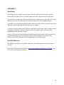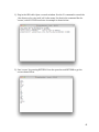
1
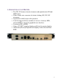
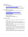
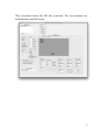
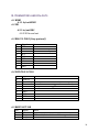
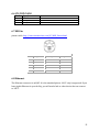
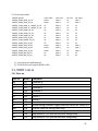
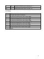
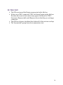
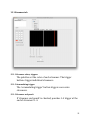
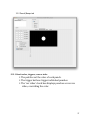
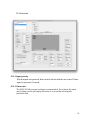
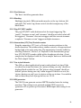
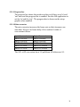
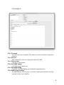
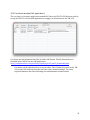
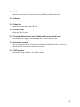
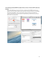
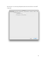
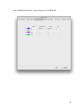
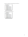
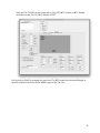
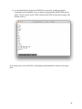
VM-‐15A Streamer V4.00.6 User’s Guide Endpoint Technology, LLC 26624 Ocean View Drive Malibu CA U.S. 90265 Technical Questions Contact: Jim Ketcham [email protected] Index to VM-‐15A Users Guide 1. Product Description 2. Quick Start 2.1 Install the FTDI USB driver 2.2 Get the GUI 2.3 Connect the VM-‐15A 2.4 Finding the version info 2.5 Buttons and indicators 2.6 Naming 3. Warranty and program updates 3.1 Warranty 3.2 Updates and how to install them 4. Installation 4.1 Power 4.2 Cooling 5. DVI/HDMI Setup 5.1 EDID 5.2 Distribution systems that block EDIDs 6. Connectors and pin-‐outs 6.1 HDMI 6.1.1 In/out HDMI 6.2 SDI 6.2.1 in/out BNC 6.3 RS422 9 PIN D 6.4 EVENTS IN 9 PIN D 6.5 BEEPS OUT XLR 6.6 LTC/POP IN XLR 6.7 MIDI in 6.8 Ethernet 7. Supported formats 7.1 SDI 7.1.1 SMPTE 259 7.1.2 SMPTE 274 7.1.3 SMPTE 295 7.1.4 SMPTE 296 7.2 HDMI 8. Operational features 8.1 Streamer 8.1.1 Streamer and end bar color 8.1.2 Width 8.1.3 Rate 8.1.4 Multiple streamers 8.1.5 Transparency 3 8.1.6 Stubby streamers 8.1.7 End punch 8.2 Punch/Beeps 8.2.1 Color 8.2.2 Reverse video 8.2.3 Size 8.2.4 Duration 8.2.5 Repeat count 8.2.6 Repeat seconds 8.2.7 Enables 8.3 Annunciator 8.4 LTC/MTC window 8.5 Picture only during cue 8.6 Picture when stopped 9. Triggering 9.1 Closures 9.2 MIDI 9.3 LTC 9.4 MTC 9.5 Pop 9.6 GUI 10. Conversions 10.1 SDI to HDMI 10.2 HDMI to SDI 10.3 Conversion table 11. MIDI tables 11.1 Note on 11.2 Velocity 11.3 Annunciator 11.4 Annunciator colors 12. Mac GUI 12.1 Streamer tab 12.1.1 Streamer colors, triggers 12.1.2 Accumulating trigger 12.1.3 Streamer end punch 12.1.4 Width/bottom/top/transparent sliders 12.1.5 Duration seconds 12.2 Punch/beeps tab 12.2.1 Punch colors, triggers, reverse video 12.2.2 Punch/beeps timing 12.2.3 Size 12.2.4 Positioning 12.3 Setup tab 12.3.1 Input priority 4 12.3.2 Frame rate 12.3.3 Test Patterns 12.3.4 Masking 12.3.5 Pop/LTC enables 12.3.6 Annunciator/LTC/Text 12.3.7 Cue in/out behavior 12.3.8 SDI generator 12.3.9 Progress bar 12.3.10 Rate converter 12.4 Debug tab 12.4.1 Transmit 12.4.2 Receive 12.4.3 Clear rx text 12.4.4 Get HDMI timing 12.4.5 Extended timing 12.4.6 Streamer fields 12.5 Cue sheet window (ALE application) 12.5.1 Add 12.5.2 Remove 12.5.3 Send text 12.5.4 Clear screen 12.5.5 ‘Include dialog in text’ and ‘include ID in text’ check boxes 12.5.6 Streamer seconds 12.5.7 MTC window 12.6 Setting up network MIDI to connect cue sheet to Protools MTC and the VM-‐15A 13. Application notes 13.1 MIDI test setup 13.2 ProTools 13.2.1 Network MIDI with cue sheet method 13.2.2 MIDI track method 13.2.3 Pop track method 5 14. Sony protocol commands 14.1 10.11 device type request 14.2 40.10 mark in 14.3 40.11 mark out 14.4 40.14 in preset 14.5 40.15 out preset 14.6 61.0c current time sense 14.7 61.20 status sense 6 1. DESCRIPTION OF THE VM-‐15A • The VM-‐15 Streamer inserts streamers and punches into SDI and HDMI video. • It has a frame rate converter for better looking 24P, 25P, 30P streamers. • It generates audio beeps on the punches. • It can be triggered from a number of sources-‐ closures, MIDI, network MIDI, or from the graphical user interface. • It converts SDI to HDMI. • It has a LTC/MTC window display and Protools counter display. • A Rehearse/Record/Playback text display can be selected from MIDI. 7 2. QUICK START 2.1 Install the FTDI USB driver § Get the USB driver for your Mac or Windows computer from http://www.ftdichip.com/Drivers/VCP.htm. § Install it. The USB port is used for setting up fixed IP addresses, and although it is not used in every day operation it is a useful setup tool. 2.2 Get the GUI and ALE application § Get the GUI and ALE application for your Intel Mac OS 10.6 or greater computer at http://endpointonline.com/products/styled/styled-‐ 2/vm15_downloads.html § The ALE application, a cue sheet for Mac, follows MTC from ProTools and sends cue text and in/outs to the streamer. § Unzip the executables. § Put them in a convenient location. § See APPENDIX A for fixed IP address setup. 2.3 Connect the VM-‐15A § The ‘universal’ AC supply accepts 120VAC-‐240VAC. Connect power, 12V DC. § Connect a HDMI or SDI monitor. A gray screen should display. § Connect a HDMI or SDI source. The ‘Status’ indicator should stop blinking. The input signal should appear on the display after a brief settling time as clocks lock. § Trigger a streamer with the ‘Trigger’ button. The ‘Status’ indicator flutters while the streamer is active. § Connect your Ma7 to the VM-‐15A with an Ethernet cable. The VM-‐ 15A supports 100-‐T or 10-‐T only. You will need a hub or other device to convert from 1000-‐T. If you do not have DHCP, see APPENDIX A for fixed IP address setup. When the VM-‐15A has an IP address, it will display briefly. § Run the GUI. Wait for the VM-‐15A to be found by Bonjour. It may be necessary to click the VM-‐15A off and then on in the Bonjour table. 8 This screenshot shows the VM-‐15A connected. The text windows are distributed around the screen. 9 This screenshot shows the VM-‐15A not connected. The text windows are piled in the lower left corner. In this state, click an empty row in the Bonjour selection window, then click on the VM-‐15A_streamer item. 10 2.4 Finding the version info § Select the Debug tab. § In the Transmit text box, enter ‘version’ (without the quotes) and hit RETURN. The versions of the 3 resident programs will print in the Receive text box. For example, the version set as of 9/16/13 is ‘version NE64:4.00.4 HCS08: 0101 LX45T: 4004’. 2.5 Buttons and indicators § Press the front panel ‘Trigger’ button quickly several times to trigger multiple streamers. § The ‘Status’ indicator blinks if there is no input, and goes steady if there is an input. 2.6 Naming The name that appears in the table in the upper left of the GUI can be changed. This is advised for installations where there are multiple streamers on the same network. The default name ends in 4 hex digits, the last 4 digits of the UUID. This is meant to avoid naming conflicts for multiple default-‐named units on the same network. Select the unit to be named in the table in the upper left of the GUI. Verify that it is the desired unit by triggering a streamer or punch from the GUI and observing either the video output or the flickering Status light on the unit. Go to the Debug tab. Type ‘name’ in the Transmit text box and press RETURN. The current name will print in the ‘Receive’ text box. For example, to change the name to ADR-‐5 type ‘name ADR-‐5’ and press RETURN. The VM-‐15A will go through the Bonjour announcement process and will re-‐appear in the table in the upper left of the GUI with the new name. The old name may stay there for a few minutes but will eventually go away. Select the new name to re-‐connect the GUI. 11 3. Warranty and program updates 3.1 Warranty The VM-‐15A warranty is 1-‐year parts and labor. Customer pays shipping. 3.2 Updates and how to install them Current GUI and updater programs are at http://endpointonline.com/products/styled/styled-‐ 2/vm15_downloads.html There is a separate updater as of 4.00.6. To update your VM-‐15A with the files built in to the updater, use the File/Update from defaults/Micro item first. Use the File/Update from defaults/Firmware item after the Micro update completes. DO NOT power down the unit at any time during the update, or click on any GUI buttons. Once Micro update 4.00.4 is installed, there is a recovery mode if power is lost during the firmware update. Hold the Trigger button while cycling the power. The unit will come up in a ‘minimum network service’ mode which will let you do the update over. As they are released, firmware and micro controller updates will be at our ftp site: • url: ftp://www.endpointonline.com • user name: VM-‐[email protected] • password: VM-‐15A 4. INSTALLATION 4.1 Power § The ‘universal’ 120-‐240 VAC supply has U.S. style pins. 4.2 Cooling The voltage regulators are heat sunk to the bottom of the case. ü Leave an air space below the unit for cooling. 12 5. DVI/HDMI SETUP 5.1 EDID The EDID table in the monitor describes the monitor’s capabilities. It is transmitted to the host on power up or connection. The VM-‐15A stores the last EDID in FLASH so that even if the monitor is not powered up the host gets the correct EDID. The VM-‐15A default EDID is from a Dell 24” 1920 x 1080 monitor. You may have to refresh the monitors on your computer (i.e. refresh the EDID) after changing monitors. 5.2 Distribution systems that block EDIDs If a monitor is detected but no EDID is returned after a timeout, HDMI output is turned on and the default EDID is used. § To set the default EDID, connect the VM-‐15A directly to the device that you wish to be the default. § Cycle the VM-‐15A power and wait for a stable image on the HDMI monitor. The device EDID has been stored in VM-‐15A FLASH. 13 6. CONNECTORS AND PIN-‐OUTS 6.1 HDMI 6.1.1 In/out HDMI 6.2 SDI 6.2.1 in/out BNC 4:2:2 SDI in and out. 6.3 RS422 9 PIN D (Sony protocol) Pin 1 2 3 4 5 6 7 8 9 Signal GND TX-‐ RX+ N/C N/C N/C TX+ RX-‐ GND Notes Pinned out as sony device (1:1 cable to editor) 6.4 EVENTS IN 9 PIN D Pin 1 2 3 4 5 6 7 8 9 Signal Punch 2 Punch 1 Streamer 2 Streamer 1 N/C GND GND GND GND Notes Immediate streamer trigger of streamer 2 only multiple streamer trigger 6.5 BEEPS OUT XLR Pin 1 2 3 Signal shield Beeps+ Beeps-‐ Notes Differential, but not balanced. Do not ground either side. 14 6.6 LTC/POP IN XLR Pin 1 2 3 Signal shield LTC/POP IN+ LTC/POP IN-‐ Notes 6.7 MIDI in pinout credit: http://www.interfacebus.com/PC_MIDI_Pinout.html MIDI Pin Out Pin No. IN Signal Name THRU Signal Name Out Signal Name 1 No Connect No Connect No Connect 2 No Connect Shield Shield 3 No Connect No Connect No Connect 4 IN+ +5v +5v 5 IN- IN IN 6.8 Ethernet The Ethernet connector is an RJ45. It is the standard pinout. 100-‐T only is supported. If you have gigabit Ethernet in your facility, you will need a hub or other device that can convert to 100-‐T. 15 7. SUPPORTED FORMATS 7.1 SDI 7.1.1 SMPTE 259 480i 29.97hz, 25hz 7.1.2 SMPTE 274 (1080p x1920) PsF 30, 25, 24 FPS 7.1.3 SMPTE 295 (1080i x 1920) 25 FPS 7.1.4 SMPTE 296 (720p x 1280) 60, 50, 30, 25, 24 FPS 7.2 HDMI The maximum HDMI resolution is 1920 x 1200 60P. 16 8. OPERATIONAL FEATURES 8.1 Streamer 8.1.1 Streamer and end bar color 8.1.2 Width 8.1.3 Rate § Use the palette to set the streamer and end bar colors. The GUI width slider on the streamer tab sets the width. The GUI rate up/down control on the streamer tab sets the streamer rate in seconds. 8.1.4 Multiple streamers Up to 4 streamers may be active at once. 8.1.5 Transparency The GUI transparency slider on the streamer tab sets the transparency of the streamer. 8.1.6 Stubby streamers The GUI top and bottom sliders on the streamer tab set the top and bottom of the streamer. Check the GUI ‘end punch’ check box to trigger a punch at the end of the streamer. Streamers 1-‐4 trigger punches 1-‐4. 8.1.7 End punch 8.2 Punch/Beeps 8.2.1 Color § Use the palette to set the punch colors. 8.2.2 Reverse video Punches may be done as reverse video rather than in color by checking the GUI check box. Set the punch size using the GUI ‘size’ slider. 8.2.3 Size 17 8.2.4 Duration Set the punch/beeps duration frames using the GUI ‘duration frames’ up/down control. 8.2.5 Repeat count Set the punch/beeps repeat count using the GUI ‘repeat count’ up/down control. For ADR the typical setting is 2 repeats. This is the number of punch/beeps after the initial punch/beep. 8.2.6 Repeat seconds Set the punch/beeps repeat seconds using the GUI ‘repeat seconds’ up/down control. For ADR the typical setting is .66 seconds. 8.2.7 Enables There are individual enable check boxes for punch and beeps. 8.3 Annunciator § § § Select one of the Rehearse/Record/Playback radio buttons to make the annunciator visible. Move the annunciator window in the GUI positioning graphic to position it. The size, foreground and background colors may be set in the GUI. The PLAYBACK annunciator inhibits streamers, punches, and text overlay. 8.4 LTC/MTC window Make a selection the ‘Display’ dropdown or move the LTC/MTC window in the GUI positioning graphic to make the LTC window visible. The size, foreground and background colors may be set in the GUI. 8.5 Picture only during cue ‘Picture only during cue’ outputs black when not in the cue. This checkbox works only when triggering from LTC lists, there is an ‘end’ timecode as the second entry in the cue, and the annunciator is selected to Rehearse, Record, or Playback. 8.6 Picture when stopped The ‘Picture when stopped’ checkbox defeats ‘Picture only during cue’ when stopped. 18 9. TRIGGERING 9.1 Closures Closures to GND on the Events connector trigger events, see the Events pinouts 6.4. § The streamer 1 closure is used to trigger multiple streamers. 9.2 MIDI MIDI notes trigger events. § See the MIDI tables 11.1,2 for the mapping of notes and velocities to events. § See the ProTools MIDI Application Note (see application notes, section 13) for more information about MIDI trigger tracks. 9.3 LTC The LTC reader can trigger events. § In/out times can be supplied from the MTC cue sheet § A Sony controller may provide the in/outs. § Set the GUI to LTC triggering 9.4 MTC The MTC reader can trigger events. § In/out times can be supplied from the MTC cue sheet § Set the GUI to MTC triggering 9.5 Pop Pops can trigger events. § Pops must be 300hz-‐3Khz and at least 10 cycles long. § Set the GUI to pop triggering 9.6 GUI The GUI is used to trigger events to check the setup. § Clicking the color boxes will trigger streamers or punch/beeps. § The streamer ‘trigger’ button triggers multiple streamers. 10. CONVERSIONS 10.1 SDI to HDMI See the conversion table below for currently supported conversions. 10.2 HDMI to SDI Proper conversion of HDMI to SDI (i.e. rate conversion to 148.5 or 148.352mhz) is not available in V4.00.0. 19 10.3 Conversion tables SMPTE formats hdmi->hdmi hdmi->sdi sdi->sdi sdi->hdmi SMPTE_260M_1035i_30_Hz Note 1 Note 2 ok Note 1 SMPTE_295M_1080i_25_Hz Note 1 Note 2 ok Note 1 SMPTE_274M_1080i_or_1080sF_30_Hz ok Note 2 ok ok SMPTE_274M_1080i_or_1080sF_25_Hz ok Note 2 ok ok SMPTE_274M_1080p_30_Hz ok Note 2 ok ok SMPTE_274M_1080p_25_Hz ok Note 2 ok ok SMPTE_274M_1080p_24_Hz ok Note 2 ok ok SMPTE_296M_720p_60_Hz ok Note 2 ok ok SMPTE_274M_1080sF_24_Hz ok Note 2 ok ok SMPTE_296M_720p_50_Hz ok Note 2 ok ok SMPTE_296M_720p_30_Hz Note 1 Note 2 ok Note 1 SMPTE_296M_720p_25_Hz Note 1 Note 2 ok Note 1 SMPTE_296M_720p_24_Hz Note 1 Note 2 ok Note 1 SMPTE_259M_480i_30_Hz ok Note 2 ok ok SMPTE_259M_480i_25_Hz ok Note 2 ok ok 1) conversion not implemented. 2) V4.00.00 does not support HDMI to SDI. 11. MIDI TABLES 11.1 Note on Note On G9 F#9 F9 E9 D#9 D9 C#9 C9 B8 A#8 A8 G8 F#8 Note # 127 126 125 124 123 122 121 120 119 118 117 116 115 Command Streamer 4 Streamer 3 Streamer 2 Streamer 1 Punch 4 Punch 3 Punch 2 Punch 1 accumulating streamer trigger (same as closure on ‘Events In’) End Bar (used for setting color only) Velocity selects annunciator message, see annunciator table Deprecated 3.33.3 (was annunciator background) Deprecated 3.33.3 (was annunciator foreground) 20 F8 E8 D#8 114 113 112 Playback annunciator colors, see table 11.4 Record annunciator colors, see table 11.4 Rehearse annunciator colors, see table 11.4 11.2 Velocity Velocity 0 1 2 3 4 5 6 7 8 9 All others Action No action (MIDI Note Off command) Set selected streamer/punch color to white, trigger Set selected streamer/punch color to yellow, trigger Set selected streamer/punch color to cyan, trigger Set selected streamer/punch color to green, trigger Set selected streamer/punch color to magenta, trigger Set selected streamer/punch color to red, trigger Set selected streamer/punch color to blue, trigger Set selected streamer/punch color to black, trigger Set selected punch color to reverse video, trigger Trigger 21 (11. MIDI TABLES , continued) 11.3 Annunciator Note that the PLAYBACK annunciator inhibits streamers, punches, and text overlay. Turn off the PLAYBACK annunciator if you want to do manual triggers. Velocity Annunciator message 0 1 2 3 4 No action (MIDI Note Off command) off ‘Rehearse’ ‘Record’ ‘Playback’ 11.4 Annunciator colors add the background color and foreground color values together, send as the velocity. ‘00’, white on white, is ignored because it is a MIDI Note Off command. Velocity Background color 0 8 16 32 48 64 80 96 112 white clear yellow cyan green magenta red blue black Velocity Foreground color 0 1 2 3 4 5 6 7 white yellow cyan green magenta red blue black 22 23 12. MAC GUI § The GUI version and the Bonjour name print in the title bar. § If there is no VM15 connected, ‘VM15 not found’ prints in the title bar. Recently disconnected streamers may appear briefly in the ‘VM15 Streamers’ Bonjour table until Bonjour detects that they are no longer connected. § The GUI has a bypass checkbox that defeats all of the various overlays. § The ‘Annunciator’ group box selects annunciator text. 24 12.1 Streamer tab 12.1.1 Streamer colors, triggers The palettes set the color of each streamer. The trigger buttons trigger individual streamers. 12.1.2 Accumulating trigger The ‘accumulating trigger’ button triggers successive streamers. 12.1.3 Streamer end punch If ‘streamer end punch’ is checked, punches 1-‐4 trigger at the end of streamers 1-‐4. 25 12.1.4 Width/bottom/top/transparent sliders The sliders set the width, bottom, top, and transparency of the streamers. 12.1.5 Duration seconds The ‘ up/down control has a range of 1-‐4 seconds. 26 12.2 Punch/Beeps tab 12.2.1 Punch colors, triggers, reverse video § The palettes set the color of each punch. § The trigger buttons trigger individual punches. § The ‘rev video’ check box displays punches as reverse video, overriding the color. 27 12.2.2 Punch/beeps timing § The ‘duration frames’ up/down control sets the duration of the punch/beep. § The ‘repeat count’ up/down control is the number of times the punch/beep repeats after the initial punch/beep. § The ‘repeat seconds’ up down control sets the repeat interval. § The ‘punch enable’ and ‘beep enable’ check boxes enable punches and beeps. 12.2.3 Size The ‘size’ slider sets the size of the punch. 12.2.4 Positioning The positioning graphic sets the punch position by dragging with the mouse. 28 12.3 Setup tab 12.3.1 Input priority If both inputs are present, this control selects which one is used. If one input is present, it is used. 12.3.2 Frame rate The VM-‐15A ‘follow input’ setting is recommended. If you know the input rate, locking can be sped up by fractions of a second by selecting the particular rate. 29 12.3.3 Test Patterns The ‘bars’ check box generates bars. 12.3.4 Masking Masking is in pixels. Different masks may be set for top, bottom, left and right. The ‘matte’ up/down control sets the transparency of the black mask. 12.3.5 Pop/LTC/MTC enables The pop/LTC/MTC radio buttons select the input triggering. The ‘punch’, ‘streamer accum’, and ‘streamer’ check boxes select what will be triggered. ‘Streamer’ does not retrigger until the current streamer completes. ‘Streamer accum’ triggers multiple streamers. 12.3.6 Annunciator/LTC/Text/Protools counter Drag the annuciator, LTC, text or Protools counter windows to the desired position. The windows have similar controls, a foreground and background color and a point size. The annunciator is made visible by selecting ‘Rehearse’, ‘Record’, or ‘Playback’ in the Annunciator group box. LTC/UB/MTC is made visible with a dropdown selection. A text sample may be displayed with the ‘Show sample’ button or hidden with the ‘Hide sample’ button. 12.3.7 Cue in/out behavior The ALE cue sheet application has an in and optional out time. If the cue sheet has in and out times, the ‘picture during cue only’ check box displays black outside the cue. The ‘picture when stopped’ check box defeats ‘picture during cue only’ when stopped. If there is no out, the ‘picture during cue only’ goes to picture at the cue in time. Cues with in and out times may have a progress bar, see 12.3.9. 12.3.8 SDI generator The VM-‐15A can generate various SMPTE standard rates for testing monitors. This setting is not retained and the VM15 reverts to ‘generator off’ on power up. Disconnect HDMI input when using it as a generator. 30 12.3.9 Progress bar The progress bar shows the position in the cue if there is an ‘in’ and ‘out’ time and the progress bar is enabled. Use the ALE application to set the ‘in’ and the ‘out’. The progress bar is shown on the setup graphic when enabled. 12.3.10 Rate converter The rate converter increases the frame rate so that streamers are smoother. It has a one frame delay if it is enabled. A table of conversions follows. Input frame rate Output frame rate SMPTE 296 24P SMPTE 296 60P SMPTE 296 25P SMPTE 296 50P SMPTE 296 30P SMPTE 296 60P SMPTE 274 24P SMPTE 274 24Psf SMPTE 274 30P SMPTE 274 30Psf The 24P-‐>60P conversion has a 3:2 pulldown. All others are 2:1. 31 12.4 Debug tab 12.4.1 Transmit The VM15 uses text commands. This window is used to send those commands manually. 12.4.2 Receive This window shows the text coming back from the VM15. 12.4.3 Clear rx text Clear the rx text window. 12.4.4 Get HDMI timing Get HDMI timing parameters. 12.4.5 Extended timing If checked, ‘get HDMI timing’ gets extended timing parameters. 12.4.6 Inhibit ping printing The GUI pings the VM-‐15A every 10 seconds. Checking this box hides the ping response in the receive window. 32 12.5 Cue sheet window (ALE application) The cue sheet is a separate application named ALE. Once the VM-‐15A GUI has been used to set up the VM-‐15A, use the ALE application to supply cue information to the VM-‐15A. Cue sheets are tab delineated text files in Avid’s ALE format. The file shown above is included in the .ZIP file for the ALE application. http://endpointonline.com/products/styled/styled-‐2/vm15_downloads.html Cue sheets can be edited on Excel or a text editor. The ‘Column’ key word in the ‘VM-‐ 15A_test.ale’ file indicates that the next line is the column headings. The ‘Data’ keyword indicates that lines following are tab delineated column entries. 33 12.5.1 Add Add a cue to the end. The cue can then be edited by clicking in the cells. 12.5.2 Remove Remove the selected cue. 12.5.3 Send text Send the current row to the VM-‐15A. 12.5.4 Clear screen Hide the VM-‐15A text. 12.5.5 ‘Include dialog in text’ and ‘include cue ID in text’ check boxes Uncheck both to trigger streamers from the cue sheet with no text. 12.5.6 Streamer seconds The cue is sent to the VM-‐15A one second plus this value before the cue. Set it to match the VM-‐15A streamer duration seconds. 12.5.7 MTC window Shows MTC from ProTools. See 12.8 for setup. 34 12.6 Setting up network MIDI to connect the cue sheet to Protools MTC and to the VM-‐15A Open Audio Midi Setup. Open the IAC driver window and the MIDI Network setup window. In the IAC Driver window, add a port (here shown as IAC Bus 1). In the MIDI Network setup window, create a session (here shown as Session 1). Enable the session. If the VM-‐15A is on the network it should show up in the Directory. Select it and connect it to the session. 35 Open Protools. Go to the Setup/Peripherals menu item. Select IAC Bus 1 as the MTC output port. 36 On the ‘MIDI Controllers’ tab, connect Session 1 to HUI MIDI #1. 37 Start the ALE application. Set the Input menu item to IAC Bus 1. Set the Output menu item to Session 1. 38 Start the VM-‐15A GUI. On the Setup tab, set Pop/LTC/MTC enables to MTC. Enable ‘streamer accum’. Set LTC/MTC display to MTC. Put Protools in PLAY by pressing the space bar. The MTC from Protools should display in the ALE window and on the SDI or HDMI output of the VM-‐15A. 39 13. APPLICATION NOTES 13.1 MIDI test setup MIDI was tested using ProTools 9 running under Windows 7 with an M-‐Audio ‘Midisport Uno’ 1x1 USB to MIDI converter. Note that the VM-‐15A supports ‘network MIDI’ also. § Plug your ‘out’ MIDI connector to the VM-‐15A MIDI input. Any program that generates MIDI notes and velocities can be used for this test. For Protools, the procedure is: o Add an instrument (called ‘streamer’ for this test) to the ProTools menu item ‘Setup/MIDI/MIDI Studio Setup’. o Select the Output Port to be your USB to MIDI interface. o Select Send Channel 1. o In the Mix window, select the MIDI track channel strip output to be ‘streamer’. o Open the MIDI Editor. o Enable ‘Play MIDI notes when editing’. The MIDI keyboard should trigger streamers and punches per the MIDI command table. 13.2 PROTOOLS 13.2.1 NETWORK MIDI with ALE cue sheet method: Refer to 12.6 for setup. Select a cue row in the ALE application. Press ‘send text’. The text should appear on the VM-‐15A SDI or HDMI output. If the text does not appear, check that the VM-‐15A is connected to a MIDI network session and that the ALE application output is to that session. If text does appear, run ProTools. MTC from Protools should display in the ALE application and step through the cue sheet. If MTC does not get to the ALE application, check that Protools MTC generator output is to the IAC Bus and that the IAC bus is selected as the input to the ALE application. Cues are sent to the VM-‐15A one second before the streamer starts. If streamers do not trigger, check the GUI setup tab to be sure that MTC is the trigger source and that a streamer trigger is checked. 13.2.2 MIDI track method: 40 credit: Derek Casari at Fox Studio provided this setup. 10. Setup\MIDI\Midi Studio 20. USB UNO [or otherwise] Interface if installed properly will be visible 30. Click "Add Device", name it "Streamer"" 40. Click on "OUT" arrow of UNO [or other MIDI interface] and drag it to "IN" arrow of "Streamer" device added in above step. Close AMS [Apple MIDI Setup] 50. In Pro Tools: Add "Track", "MIDI track" 60. Click on the MIDI track just created. 70. View\Edit Window Views\Real Time Properties 80. In the MIDI track o click on "DLY", o change to "-‐" [Advance], change timebase to "ms", o make the value 2000 [duration of streamer] 90. In bottom left time base select should be "samples" 100. To enter streamer values: o Locate to a point where a streamer is desired. o Change view to "notes". o On the keyboard, click on the note value B8, say at 59:30:00. (This becomes a template value.) o Switch back to "Regions" view. o Select the region where you have placed the streamer note above, hit CMD + C [copy], locate to next streamer point, and CMD + V [paste]. o Repeat for the multiple streamer points desired. 13.2.3 Pop track method This method is similar to the MIDI track method but uses an audio pop track. Pops must be 300hz-‐3Khz and at least 10 cycles long. See the Events connector table (section 6.4) for audio pop connections. 41 14. SONY PROTOCOL COMMANDS Sony protocol is 38400 baud, odd parity, one stop bit. 14.1 10 11 device type request Responses to device type request: Code type Device type 24 0x02b2 25 0x01b2 29.97/30 0x00b2 14.2 40.10 mark in • Use the current LTC reader position as the cue in point. 14.3 40.11 mark out • Use the current LTC reader position as the cue out point. 14.4 44.14 in preset • Set the cue in point from data. Send bytes: Byte 0 Value 0x44 1 0x14 2 Frames 3 Minutes 4 Seconds 5 Hours 3 Minutes 4 Seconds 5 Hours 14.5 44.15 out preset • Set the cue out point from data. Send bytes: Byte 0 Value 0x44 1 0x15 2 Frames 42 (14. Sony protocol commands, continued) 14.6 61.0c current time sense • Return the LTC reader position. Send bytes: Byte 0 Value 0x61 Receive bytes: Byte 0 Value 0x74 2 N/A 1 0x04 2 Frames 3 Minutes 4 Seconds 5 Hours 14.7 61.20 status sense Bit Byte 1 Byte 2 1 0x0c • Return status bytes. Only bytes 1 and 2 have data, all other bytes are zero. Unused bits are zero. ‘PLAY’ and ‘LOCK’ are set if the LTC reader has valid input, ‘STOP’ is set if not. 7 LOCK 6 5 STOP 4 3 2 1 0 PLAY 43 APPENDIX A Quick Start Assuming you have a DHCP server, continue with the quick start. If you don’t and have fixed addresses, please refer to ‘Fixed IP Addresses’ then continue with the quick start. Close ProTools. Connect the VM-‐15A to the network. Connect power to the VM-‐15A. The IP address of the VM-‐15A will display for a few seconds on the SDI and HDMI outputs. On the Mac, open the Network MIDI window. There should be a VM15_streamer item in the ‘Directory’ pane. It may take a few seconds for it to appear. If you do not have a MIDI session, add one to the ‘My Sessions’ pane. Call it ‘counter session’ for instance. Enable the session. Connect the VM15_streamer item to the session by highlighting it and pressing ‘Connect’. Open ProTools. In the Setup/Peripherals/MIDI Controller tab, enable a HUI controller. Set its input and output to be to the session you just created. When you close the Setup window, the VM-‐15A display should be displaying the ProTools counter. Fixed IP Addresses The USB port is used to set up fixed IP addresses. The following note uses the program ‘screen’. Install the FTDI VCP driver available at http://www.ftdichip.com/Drivers/VCP.htm if you do not have an FTDI driver installed. 44 1) Plug in the USB cable. Open a console window. Use the ‘ls’ command to search the /dev directory for a tty with ‘usb’ in the name. Use that in the command line for ‘screen’, with a 115200 baud rate. An example is shown below. 2) Start ‘screen’ by pressing RETURN. Press the space bar and RETURN to get the screen shown below. 45 3) set the fixed address (and turn off DHCP if you need to). Backspace/delete commands are not handled, so if you make a typing mistake hit RETURN and try again. To quit ‘screen’, press CTRL-‐A followed by CTRL-‐K to get the prompt at the bottom, select ‘y’. 4) cycle the power on the VM-‐15A. It will display the fixed address. Return to the quick start. 46 Using TELNET Open a console window. Close the GUI because it uses the telnet port also. If the address of the VM-‐15A is 192.168.1.41, the command telnet 192.168.1.41 will connect you to the counter for a serial session. Press space bar return to get the list of commands. Once you are done with setup, use the command bye to end the session. Telnet sessions time out in less than a minute if you do not disconnect. ****************************************************************************** If you have any questions or suggestions for additions or edits to the manual, please contact me at: [email protected] (Ignore the spam blocker message if you get one, I check the spam bin for legitimate emails often) Thank you, Jim Ketcham Endpoint Technology LLC 47 NOTES: 48