1
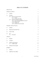
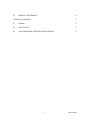
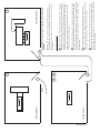
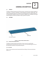
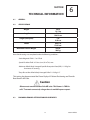
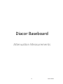
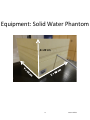
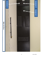
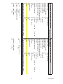
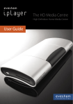
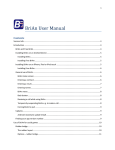
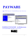
YR ZEPH Model XL User Manual DIACOR 2550 DECKER LAKE BLVD., SUITE 26, SALT LAKE CITY, UTAH 84119 800 342-2679 / 801 467-0050 / FAX: 801 487-3258 www.diacorinc.com [email protected] 800142 REV B This manual contains the latest information at the time of publication. Diacor, Inc. reserves the right to revise this manual without notice. INTENDED USE The Zephyr XL Patient Positioning and Transfer System is indicated to aid in the support, positioning, and transfer of a patient for procedures involving imaging, including MRI, and external beam radiation therapy treatment with electrons, photons or protons, as well as other procedures requiring transfer of a patient. The Zephyr XL is intended for use only by physicians qualified in imaging and/or experienced in patient set up for planning or treatment, or by therapists at the specific direction of such qualified physicians. Diacor, Inc. has appointed M. Devices Group as our EU Authorized Representative. Contact Information: M. Devices Group, Marlborough House, Riding Street, Southport, PR8 1EW, United Kingdom, Tel: +44 1704 544 944, Fax: +44 1704 544 050 Date of Publication: August 2014 ECO 50968 Zephyr is a trademark of Diacor, Inc. Diacor is a registered trademark of Diacor, Inc. Velcro is a registered trademark of Velcro Industries B.V. SANI-CLOTH® is a registered trademark of Professional Disposables International ©2012 Diacor, Inc. Printed in U.S.A. 800142 REV B Figure 1.1 Diacor Zephyr XL Patient Positioning and Transfer System Base Board 800142 REV B 800142 REV B TABLE OF CONTENTS INTRODUCTION1 GENERAL DESCRIPTION 5 2.1GENERAL 5 2.2FEATURES 2.2.1 Patient Transfer Base Board 2.2.1.1 Air Pads 2.2.1.2 Air Hose Connection 2.2.2 Zephyr XL Air Blower and Hose 2.2.2.1 Power Cord/Handheld Blower Control 2.2.2.2 ON/OFF Switch 2.2.2.3 Flexible Hose 2.2.2.4 Quick Turn Hose Connection 5 5 5 6 6 6 8 8 8 UNPACKING, INSTALLATION, USE 9 3.1GENERAL 9 3.2 9 UNPACKING AND INSPECTION 3.3INSTALLATION 9 3.4USE 3.4.1 Pinch Points 9 11 SERVICING13 4.1GENERAL 13 4.2CLEANING 13 4.3 PERIODIC MAINTENANCE 4.3.1 Air Blower Filter 13 13 4.4 HANDLING AND STORAGE 13 WARRANTY15 5.1GENERAL 15 5.2 15 WARRANTY DISCLAIMERS i 800142 REV B 5.3 WARRANTY PERFORMANCE 15 TECHNICAL INFORMATION 17 6.1GENERAL 17 6.2SPECIFICATIONS 17 6.3 17 DIACOR BASEBOARD ATTENUATION MEASUREMENTS ii 800142 REV B SECTION INTRODUCTION 1 The Zephyr XL Patient Positioning and Transfer System is used to aid in the support, positioning, and transfer of a patient for procedures involving Magnetic Resonance Imaging (MRI), Computed Tomography Imaging (CTI), Positron Emission Tomography (PET) imaging, Diagnostic Xray Imaging (DXI), Radiation Therapy (RT) treatment by Medical Linear Accelerator or Charged Particle Accelerator and other procedures requiring transfer of a patient. The Zephyr XL Patient Positioning and Transfer System consists of a rigid “MR Safe” Kevlar/Epoxy base board measuring 198.12cm x 53.01cm x 2.54cm (including pads). The underside of the base board has four perforated lift pads. The Zephyr XL Patient Positioning and Transfer System utilizes forced air as a low-friction bearing to transfer patients from one flat surface to another, eliminating the need to manually lift the patient. The forced air is provided by an accessory air blower through a 10 foot length of flexible hose connected to the base board. The air is then routed to the perforated lift pads on the underside of the base board. When being used in MR, an extended flexible hose of 30 feet is available upon request, to position the “MR Unsafe” blower unit outside an MR imaging room, and continue to remain connected. The base board is placed on a flat-surfaced wheeled stretcher (also available from Diacor). The base board is capable of attachment of various commercially available patient support and positioning accessories, utilized for imaging and treatment. The positioning aids, if required by the user, are placed upon and attached to the base board. The patient is then positioned on the base board with positioning aids, if applicable. The wheeled stretcher is then rolled to the procedure room and placed against the imaging or treatment table. The patient is transferred to the imaging or treatment table by activating the blower. As the blower supplies air to the lift pads, the pads generate a nominal lift of 1 centimeter to the base board. This lift enables the base board to be moved from one flat surface to another with ease by two persons. The medical staff guides the base board and the patient to the position desired. The base board is aligned with the index locations if available in the table. The blower is then deactivated and the base board settles on the flat supporting surface. The patient is then imaged or treated as required. During the procedure, the base board will function as an accessory to support and position the patient utilizing any non-Diacor positioning aids required by and supplied by the medical staff. After the procedure, the blower is activated and the base board and patient are transferred to the wheeled stretcher. The blower is then deactivated, and the wheeled stretcher is removed from the procedure room. 1 800142 REV B 2 800142 REV B 3 800142 REV B Set-Up Room Imaging Room Home 2 1 2 4 1 4 4 After treatment, the low-pressure blower is activated and the patient and the Zephyr base board are transferred back to the flat-topped stretcher and wheeled back to the Set-up room to be removed from the immobilization devices and the base board. 3 The patient is wheeled to the Treatment Room. The low-pressure blower is activated. While remaining on the Zephyr base board, the patient is transferred to the treatment couch where they are then treated. 2 Treatment Days 1 through n: In a Set-Up Room, the Zephyr base board is placed on a flat topped, “wheeled stretcher” (Device Product Code: FPO. Regulation Number 880.6910, Regulatory Class 1, 510(k) exempt). The patient is placed on the Zephyr and immobilized in the treatment position utilized during imaging. 1 First day in the clinic: The Zephyr base board is placed on an imaging table. The patient is placed on the Zephyr base board and immobilized in the treatment position. After the scanning/imaging takes place, the patient is removed from the immobilization devices and sent home until the first treatment day. In the meantime, the imaging data will be used to assist in radiation therapy treatment planning. The Common Workflow Benefit: Setup and disassembly of the patient’s immobilization and positioning devices can occur in a Set-Up Room. This decreases the time a patient occupies the Treatment Room and increases the time available to treat patients. Diacor Zephyr “x-series” Patient Positioning and Transfer System Workflow Treatment Room 3 4 800142 REV B SECTION GENERAL DESCRIPTION 2 2.1GENERAL The Zephyr XL Patient Positioning and Transfer System is used to aid in the support, positioning, and transfer of a patient for procedures involving Magnetic Resonance Imaging (MRI), Computed Tomography Imaging (CTI), Positron Emission Tomography (PET) imaging, Diagnostic Xray Imaging (DXI), Radiation Therapy (RT) treatment by Medical Linear Accelerator or Charged Particle Accelerator and other procedures requiring transfer of a patient. 2.2FEATURES Base Board Air Hose Connector Figure 2.1 Zephyr XL Base Board Features 2.2.1 Patient Transfer Base Board The Zephyr XL Patient Positioning and Transfer System consists of a rigid “MR Safe” Kevlar/Epoxy base board measuring 198.12cm x 53.01 cm x 2.54cm (including pads). The underside of the base board has four perforated lift pads. 2.2.1.1Air Pads Figure 2.2 shows the four air pads that provide lift to the Zephyr XL base board when the blower is on. 5 800142 REV B 2.2.1.2Air Hose Connection The hose connector accepts the mating connector on the air hose. To attach the hose, it is only necessary to insert and twist the hose connector a partial turn to lock the hose to the sled. To remove the hose, lift the collar to release the lock, then twist the entire connector and pull the hose out. 2.2.2 Zephyr XL Air Blower and Hose CAUTION Blower must remain outside of the MR Suite. This blower is “MR Unsafe”. To remain connected, a longer hose is available upon request. The Zephyr XL Patient Positioning and Transfer System utilizes forced air as a low friction bearing to transfer patients from one flat surface to another, eliminating the need to manually lift the patient. The forced air is provided by an accessory air blower through an extended length of flexible hose connected to the base board. The air is then routed to the perforated lift pads on the underside of the base board. A longer hose is available upon request to position the “MR Unsafe” blower unit outside an MR imaging room and continue to remain connected. Note: The blower has an internal filter that needs to be replaced annually or when visibly dirty. Figure 2.3 shows the air blower and hose as well as important features of the blower. 2.2.2.1Power Cord/Handheld Blower Control The blower is operated using the Rocker Switch on the connected pendant controller. When the blower is plugged in and turned on, the blue light on the Rocker Switch indicates the operating status: Light Signal Blinks Three Times Blinks Continuously No Light Signal Steady light, but rocker switch not activating blower Indication Recommended Action Ready for operation Use the rocker switch to activate the air lift when ready. Blower plugged in and turned Turn rocker switch to the OFF (down) on while rocker switch was in position. Wait five seconds. Use the activated position rocker switch to activate the air lift when ready. Blower not plugged in Verify that the blower is connected to a functioning outlet. Blower not powered on Verify that the button on top of the blower has been pressed to enable it. 6 800142 REV B Air Pads (4) Figure 2.2 Bottom View of Zephyr XL Base Board Support Hanger ON/OFF Switch Handheld Pendant Controller Flexible Hose Air Blower Power Cord Figure 2.3 Zephyr XL Air Blower and Hose 7 800142 REV B 2.2.2.2ON/OFF Switch The ON/OFF switch is a push to connect/push to disconnect power switch. The switch must be in the ON position to enable the Handheld Blower Control to control the power of the Zephyr XL blower. 2.2.2.3Flexible Hose A flexible hose carries the air from the Zephyr XL air blower to the base board. A ten (10) foot hose is supplied with the Zephyr XL blower. If requested a longer hose is available. A longer hose may be needed when used for MR imaging. 2.2.2.4Quick Turn Hose Connection A quick turn connector attached to each end of the flexible hose connects to both the air blower and the base board. 8 800142 REV B SECTION UNPACKING, INSTALLATION, USE 3 3.1GENERAL The Zephyr XL is designed ready for installation following removal from its packing container. 3.2 UNPACKING AND INSPECTION When the Zephyr XL arrives, inspect all shipping containers for evidence of physical damage. If there are any dents, scratches or other evidence of physical damage to the boxes, note the damage on the shipper’s copy of the bill of lading and file a claim against the shipper. In the case of shortages or malfunctions, notify Diacor immediately to arrange for replacement or repair. Refer to sections 5.3 for the discussion of replacement or repair of products under warranty. Save all packing containers and materials for the Zephyr XL in the event it needs to be returned to Diacor for replacement or repair. Caution Always use two people when lifting the base board to or from any flat surface. 3.3INSTALLATION Using two people, place the base board on a flat table top or stretcher(see above caution). The four air pads should be resting on the surface of the flat table top or stretcher. Connect the blower air hose to both the connector on the base board as well as the connector on the air blower. This requires only a partial turn clockwise. Plug the electrical cord from the air blower into a power outlet. Verify that the power switch is turned off and the Pendant Rocker Switch is turned off. 3.4USE WARNING Do not allow the sheet or pad to slide underneath the base board as it is important that the users know exactly where the base board is on the flat table top. Failure to control the sheet or pad may cause the base board to lift incorrectly or to catch the sheet or pad under the base board. Prior to each use the base board must be cleaned by the standard requirements of the user that fall under “any product that may come in contact with a patient.” Next, if applicable, cover the base board with a sheet or a sterile pad to protect the patient, following the standard setup for the procedure. Do not allow the sheet or pad to slide underneath the base board as it is impor- 9 800142 REV B tant that the users know exactly where the base board is on the flat table top. Failure to control the sheet or pad may cause the base board to lift incorrectly or to catch the sheet or pad under the base board. The base board is capable of attachment of various commercially available patient support and positioning accessories utilized for imaging and treatment. The base board is now ready for placement of positioning aids, if required, and ISO ready for the patient. The positioning aids, if required by the user, are placed upon and attached to the base board. The patient is then positioned on the base board and immobilized as per physician’s instructions. The patient is transferred to the required position by activating the blower. On the air blower, ensure that the power switch on. Flip the Pendant Rocker Switch toward the blue light to initiate the air flow. As the blower supplies air to the lift pads, the pads generate a nominal lift of 1 centimeter to the base board. This lift enables the base board to be moved from one flat surface to another with ease by two persons. Adjust the lift with the variable power control. The medical staff guides the base board and the patient to the position desired. The base board is aligned with the index locations if available in the table. The blower is then deactivated and the base board settles on the flat supporting surface. The patient is then imaged or treated as required. During the procedure, the base board will function as an accessory aid to support and position the patient, utilizing any non-Diacor positioning aids required by and supplied by the medical staff. After the procedure, the blower is activated and the base board and patient are transferred to the wheeled stretcher. The blower is deactivated and the wheeled stretcher is removed from the procedure room. Caution It is extremely easy to move a patient that has been lifted by the air pads. However, for safety purposes, two people must assist in moving the patient whenever the base is supported by the air pads. WARNING There are no stops at either end of the flat table top. It is important that the users control the base board as it is moved to the extreme ends of the flat table top and prevent it from extending over the flat table top. The patient should not be moved on the base board with the air pads inflated at the same time that the table is moving. 10 800142 REV B 3.4.1 Pinch Points Caution Prevent pinched fingers. Whenever the Zephyr XL base board is elevated by the air pads, it is possible for the users or the patient to allow their fingers to go underneath the base. When the blower is turned off, the base board will lose its lift and may pinch fingers that are beneath it. 11 800142 REV B 12 800142 REV B SECTION SERVICING 4 4.1GENERAL The Zephyr XL requires careful handling and cleaning following each use but generally requires minimal service. 4.2CLEANING The Zephyr XL makes noncritical patient contact, but these contact areas must be thoroughly cleaned following each use to prevent spread of infection by contact. 4.2.1 Cleaning Method After each use, wipe the surfaces of the base board with wipes containing a mild cleaning and disinfecting solution of 14% alcohol and active quaternary ammonium chlorides or a similar disinfecting solution. (One such solution is offered by Professional Disposables International with a trade name of SANI-CLOTH® PLUS). After the cleaning process is complete, let the cleaned surfaces air dry. Do not use water as either a cleaning or rinsing agent. Never use aerosol cleaning sprays, cleaning agents, solvents or abrasive detergents. 4.3 PERIODIC MAINTENANCE Diacor recommends inspecting the base board monthly for broken or non-functioning parts. Contact Diacor for replacement parts. See section 5.3. Replace the plastic hose cover as needed. 4.3.1 Air Blower Filter The filter in the Zephyr XL air blower should be cleaned or replaced annually or when visibly dirty. There are three screws that must be removed to separate the blower from the canister and allow access to the filter. The filter can be cleaned with water or replaced and the three screws returned to their original position. Filter replacements are available from Diacor. 4.4 HANDLING AND STORAGE Handle the Zephyr XL carefully to prevent damage. Store in a safe place when not in use. 4.5 AIR PADS Should an air pad be damaged, please contact Diacor for service. For contact information see section 5.3. 13 800142 REV B 14 800142 REV B SECTION WARRANTY 5 5.1GENERAL The Zephyr XL is warranted by Diacor for a period of one (1) year from the date of shipment. The Diacor warranty coverage is limited to defective materials or workmanship. The warranty is void if the Zephyr XL has been damaged by accident, unreasonable or improper use, neglect, or other causes not arising out of defects in material or workmanship. 5.2 WARRANTY DISCLAIMERS The express warranty provided herein is in lieu of any and all implied warranties arising out of the sale of the Zephyr XL, including but not limited to the implied warranties of merchantability and fitness for a particular purpose. Diacor shall not be liable for loss of use of the Zephyr XL or other incidental or consequential costs, expenses, or damages incurred by the customer or other users. 5.3 WARRANTY PERFORMANCE During the stated warranty period, the Zephyr XL will be repaired or replaced, at the option of Diacor, Inc., with a new or reconditioned Zephyr XL when the units are returned shipping prepaid to Diacor, Inc., 2550 Decker Lake Blvd., Suite 26, Salt Lake City, Utah 84119. Please contact Diacor, 800-342-2679 or 801-467-0050, for a Return Material Authorization (RMA) prior to sending the defective unit back. The replacement of a Zephyr XL will not extend the expressed warranty stated herein beyond the original warranty period. 15 800142 REV B 16 800142 REV B SECTION TECHNICAL INFORMATION 6 6.1GENERAL 6.2SPECIFICATIONS Weight 28 lb. 12.7 kg. 78 in. 198.12 cm. 1 in. 2.54 cm. 20.87 in. 53.01 cm. 450 lb. 204 kg. Length Height (with pads) Width Maximum Patient Weight Non-clinical testing was completed under the following conditions: -Static Magnetic Field: 1.5 to 3 Tesla -Spatial Gradient Field: 4.5 Gauss/cm (45 mT/m) max. -Maximum Whole Body Averaged Specific Absorption Rate (SAR): 1.1 W/kg for 10 minutes of scanning. -Temp Rise at Max. Whole Body Averaged SAR of 1.1 W/kg: 0 °C This testing has demonstrated the Diacor Zephyr XL Patient Positioning and Transfer Base Board is MR Safe. Caution Blower must remain outside of the MR suite. This blower is “MR Unsafe”. To remain connected, a longer hose is available upon request. 6.3 DIACOR BASEBOARD ATTENUATION MEASUREMENTS 17 800142 REV B Diacor Baseboard A.enua1on Measurements 18 800142 REV B Equipment: Solid Water Phantom Z= 20 cm 19 800142 REV B Equipment: Farmer Chamber 20 800142 REV B Equipment: Electrometer 21 800142 REV B General Setup in the Presence of the Diacor Baseboard 22 800142 REV B Location 3 Anterior View Location 1 Location 2 800142 REV B 23 Location 1 Location 2 Location 3 Posterior View 800142 REV B 24 Diacor Baseboard Attenuation Measurement: Static Diacor Baseboard Attenuation Measurement: Arc Location 3: Solid Board AF 1.4% Setup Parameter and Equipment Chamber Type Chamber Type FC65-G (Farmer) FC65-G (Farmer) Chamber Serial Number 730 Chamber Serial Number 730 Chamber Leakage Chamber Leakage 0 0 Chamber Calibration Chamber Calibration 28-Dec-10 28-Dec-10 Electrometer Type Electrometer Type Unidose-E Unidose-E Electrometer Serial Numbe 00499 Electrometer Serial Numbe 00499 Electrometer Calibration 3-Jan-11 Electrometer Calibration 3-Jan-11 Phantom Phantom Solid Water Solid Water Phantom Dimension Y = 30 cm Z = 20 cm Phantom Dimension Y = 30 cm Z = 20 cm X = 30 cm X = 30 cm SSD SSD 90 cm 90 cm Field Size Field Size 10 cm X 10 cm 10 cm X 10 cm Chamber Depth Chamber Depth 10 cm 10 cm MU MU 200 200 Energy Energy 10 MV 10 MV DR DR 600 600 Diacor Base Board on top of solid water phantom when needed Diacor Base Board on top of solid water phantom when needed Measurements Location 1: Bladder with Hole AF 3.0% Location 1: Bladder with Hole AF 0.5% Location 2: Bladder with no Hole AF 3.3% Location 3: Solid Board AF 1.7% 800142 REV B 25 Diacor Baseboard Attenuation Measurement: Static Diacor Baseboard Attenuation Measurement: Arc Setup Parameter and Equipment Location 1: Bladder with Hole AF 3.8% Chamber Type Chamber Type FC65-G (Farmer) FC65-G (Farmer) Chamber Serial Number Chamber Serial Number 730 730 Chamber Leakage Chamber Leakage 0 0 Chamber Calibration Chamber Calibration 28-Dec-10 28-Dec-10 Electrometer Type Electrometer Type Unidose-E Unidose-E Electrometer Serial Number 00499 Electrometer Serial Number 00499 Electrometer Calibration Electrometer Calibration 3-Jan-11 3-Jan-11 Phantom Phantom Solid Water Solid Water Phantom Dimension Y = 30 cm, Z = 20 cm Phantom Dimension Y = 30 cm, Z = 20 cm X = 30 cm X = 30 cm SSD SSD 90 cm 90 cm Field Size Field Size 10 cm X 10 cm 10 cm X 10 cm Chamber Depth Chamber Depth 10 cm 10 cm MU MU 200 200 Energy Energy 6 MV 6 MV DR DR 600 600 Diacor Base Board on top of solid water phantom when needed Diacor Base Board on top of solid water phantom when needed Measurements Location 1: Bladder with Hole AF 1.1% Location 2: Bladder with no Hole AF 4.4% 2.1% Location 3: Solid Board AF Location 3: Solid Board AF 1.7% 800142 REV B 26 Depth of Measurement in mm 1 2 3 5 7 9 11 13 15 16 17 19 21 23 24 25 PTW Advanced Markus Plane Parallel Chamber TN34045 0 Not Applicable Unidose-‐E 00499 3-‐Jan-‐11 Setup Parameter and Equipment Diacor Baseboard Build-‐up Measurement: Static Chamber Type Chamber Serial Number Chamber Leakage Chamber Calibration Electrometer Type Electrometer Serial Number Electrometer Calibration Raw Readings With Board 6 MV 10 MV 0.719 0.613 0.737 0.644 0.748 0.668 0.763 0.707 0.768 0.734 0.768 0.753 0.764 0.765 0.760 0.771 0.754 0.774 0.751 0.775 0.776 0.774 0.772 0.769 0.766 0.762 Dose Relative to Dmax With Board 6 MV With Board 10 MV With Board 93.7% 79.0% 96.0% 83.0% 97.4% 86.1% 99.3% 91.1% 100.0% 94.6% 100.0% 97.0% 99.5% 98.6% 99.0% 99.4% 98.2% 99.7% 97.7% 99.9% 100.0% 99.7% 99.5% 99.1% 98.7% 98.2% Date: 11/12/2012 Dose Relative to Dmax Without Board 6 MV Without Board 10 MV Without Board 48.2% 33.0% 64.2% 46.2% 73.9% 55.2% 86.9% 69.7% 93.9% 79.5% 97.6% 86.4% 99.2% 90.8% 100.0% 94.3% 100.0% 96.6% 99.6% 97.3% 99.6% 98.4% 99.3% 99.7% 100.0% 99.9% 99.7% Phantom Solid Water Phantom Dimension X = 30 cm Y = 30 cm Z = 20 cm SSD 100 Field Size 10 cm X 10 cm Chamber Depth Variable MU 100 Energy 6 MV and 10 MV DR 600 MU/Min Diacor Base Board on top of solid water phantom when needed Raw Readings Without Board 6 MV 10 MV 0.366 0.253 0.487 0.355 0.561 0.424 0.660 0.536 0.713 0.611 0.741 0.664 0.753 0.698 0.759 0.725 0.759 0.743 0.757 0.748 0.756 0.756 0.763 0.767 0.769 0.768 0.766 800142 REV B 27 Diacor Baseboard Build-‐up Measurement: Static Date: 11/12/2012 120.0% Depth Dose (%) 100.0% 80.0% 6 MV Without Board 10 MV Without Board 60.0% 6 MV With Board 10 MV With Board 40.0% 20.0% 0.0% 0 5 10 15 Depth of Measurement (mm) 20 25 Warning: Materials in the Zephyr XL have been measured and determined to be approximately 6mm tissue equivalent for both 6MV and 10MV. As these measurements are machine and energy dependent each site must make their own measurements before using. 28 800142 REV B 30