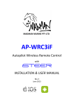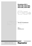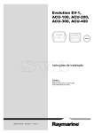
1
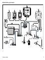
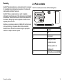
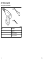
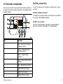
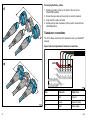
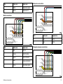
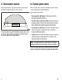
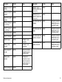
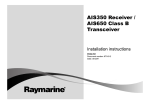
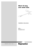
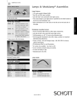
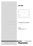
iTC -5
Ins ta lla tion ins tructions
ENGLIS H
Docume nt numbe r: 87138-3
Da te : 03-2012
Trademark and patents notice
Autohelm, hsb2, RayTech Navigator, Sail Pilot, SeaTalk, SeaTalkNG, SeaTalkHS and Sportpilot are registered trademarks of Raymarine
UK Limited. RayTalk, Seahawk, Smartpilot, Pathfinder and Raymarine are registered trademarks of Raymarine Holdings Limited.
FLIR is a registered trademark of FLIR Systems, Inc. and/or its subsidiaries.
All other trademarks, trade names, or company names referenced herein are used for identification only and are the property of
their respective owners.
This product is protected by patents, design patents, patents pending, or design patents pending.
Fair Use Statement
You may print no more than three copies of this manual for your own use. You may not make any further copies or distribute or use the
manual in any other way including without limitation exploiting the manual commercially or giving or selling copies to third parties.
Software updates
Check the website www.raymarine.com for the latest software releases for your product.
Product handbooks
The latest versions of all English and translated handbooks are available to download in PDF format from the website www.raymarine.com.
Please check the website to ensure you have the latest handbooks.
Copyright ©2012 Raymarine UK Ltd. All rights reserved.
ENGLISH
Document number: 87138-3
Date: 03-2012
Contents
Chapter 1 Important information............................. 7
5.6 Technical specification............................................... 34
Safety notices................................................................. 7
5.7 NMEA2000 sentences............................................... 35
Chapter 2 Planning the installation ........................ 9
Chapter 6 Options and accessories ....................... 37
2.1 About the iTC-5 Converter ......................................... 10
2.2 Handbook information ............................................... 11
6.1 Spares ..................................................................... 38
6.2 SeaTalkng cables and accessories .............................. 38
2.3 System examples...................................................... 11
2.4 Pack contents ........................................................... 15
2.5 Tools required ........................................................... 16
Chapter 3 Cables and connections......................... 17
3.1 General cabling guidance .......................................... 18
3.2 Converter connections............................................... 19
Chapter 4 Location and mounting .......................... 25
4.1 Unit dimensions ........................................................ 26
4.2 Mounting .................................................................. 26
4.3 Removing the front cover........................................... 28
Chapter 5 System checks and troubleshooting .............................................................................. 29
5.1 Serial number location............................................... 30
5.2 Typical system checks............................................... 30
5.3 iTC-5 LED Status indicators....................................... 31
5.4 System data troubleshooting...................................... 33
5.5 Raymarine customer support ..................................... 34
5
6
iTC-5
Chapter 1: Important information
Caution: Power supply protection
Safety notices
When installing this product ensure the power source
is adequately protected by means of a suitably-rated
fuse or automatic circuit breaker.
Warning: Switch off power supply
Ensure the vessel’s power supply is switched OFF
before starting to install this product. Do NOT connect
or disconnect equipment with the power switched on,
unless instructed in this document.
Warning: Exposed wires
With the cover open the exposed transducer wires
provide a potential for electric shock.
Caution: Service and maintenance
This product contains no user serviceable
components. Please refer all maintenance and repair
to authorized Raymarine dealers. Unauthorized repair
may affect your warranty.
Declaration of conformity
Raymarine Ltd. declares that this product is compliant with the
essential requirements of EMC directive 2004/108/EC.
Warning: Potential ignition source
The original Declaration of Conformity certificate may be viewed on
the relevant product page at www.raymarine.com.
This product is NOT approved for use in
hazardous/flammable atmospheres. Do NOT install in
a hazardous/flammable atmosphere (such as in an
engine room or near fuel tanks).
EMC installation guidelines
Warning: Product installation and
operation
This product must be installed and operated in
accordance with the instructions provided. Failure to
do so could result in personal injury, damage to your
vessel and/or poor product performance.
Raymarine equipment and accessories conform to the appropriate
Electromagnetic Compatibility (EMC) regulations, to minimize
electromagnetic interference between equipment and minimize the
effect such interference could have on the performance of your
system
Correct installation is required to ensure that EMC performance is
not compromised.
For optimum EMC performance we recommend that wherever
possible:
• Raymarine equipment and cables connected to it are:
– At least 1 m (3 ft) from any equipment transmitting or cables
carrying radio signals e.g. VHF radios, cables and antennas.
Important information
7
In the case of SSB radios, the distance should be increased
to 7 ft (2 m).
– More than 2 m (7 ft) from the path of a radar beam. A radar
beam can normally be assumed to spread 20 degrees above
and below the radiating element.
• The product is supplied from a separate battery from that used
for engine start. This is important to prevent erratic behavior
and data loss which can occur if the engine start does not have
a separate battery.
• Raymarine specified cables are used.
• Cables are not cut or extended, unless doing so is detailed in
the installation manual.
Note: Where constraints on the installation prevent any of
the above recommendations, always ensure the maximum
possible separation between different items of electrical
equipment, to provide the best conditions for EMC performance
throughout the installation
contain. In addition, our policy of continuous product improvement
may change specifications without notice. As a result, Raymarine
cannot accept liability for any differences between the product
and this document. Please check the Raymarine website
(www.raymarine.com) to ensure you have the most up-to-date
version(s) of the documentation for your product.
Warranty registration
To register your Raymarine product ownership, please visit
www.raymarine.com and register online.
It is important that you register your product to receive full warranty
benefits. Your unit package includes a bar code label indicating the
serial number of the unit. You will need this serial number when
registering your product online. You should retain the label for future
reference.
Product disposal
Dispose of this product in accordance with the WEEE Directive.
The Waste Electrical and Electronic Equipment (WEEE)
Directive requires the recycling of waste electrical and electronic
equipment. Whilst the WEEE Directive does not apply to some
Raymarine products, we support its policy and ask you to be aware
of how to dispose of this product.
Technical accuracy
To the best of our knowledge, the information in this document
was correct at the time it was produced. However, Raymarine
cannot accept liability for any inaccuracies or omissions it may
8
iTC-5
Chapter 2: Planning the installation
Chapter contents
•
2.1 About the iTC-5 Converter on page 10
•
2.2 Handbook information on page 11
•
2.3 System examples on page 11
•
2.4 Pack contents on page 15
•
2.5 Tools required on page 16
Planning the installation
9
2.1 About the iTC-5 Converter
• AWA — Apparent wind angle
The iTC-5 converter allows connection of a range of compatible
analogue transducers directly to the SeaTalkng network.
• AWS — Apparent wind speed
• Depth
• STW — Speed through water
• Log distance
• Trip distance
• Sea temperature
• Rudder angle
• Vessel Heading
D12026-1
Supported transducers and data types
The following transducer types are supported by the converter:
• Instrument depth
• Instrument speed and sea temperature
• Raymarine Wind or rotavecta
• Rudder reference
• Fluxgate compass
Note: If there is a fishfinder in the system ensure that it does
not operate at the same frequency as the instrument depth
transducer.
Supported data types are as follows:
10
iTC-5
2.2 Handbook information
2.3 System examples
This handbook describes how to include the iTC-5 converter within
a SeaTalkng network, and connect compatible transducers.
The iTC-5 converter can be connected into a SeaTalkng network,
compatible transducers can then be connected directly to the
converter.
iTC-5 handbooks
Description
Part number
Instrument transducer converter iTC-5
Installation instructions
87138
Basic SeaTalkng system example
2
1
Additional handbooks
You may also need the additional information included in the
SeaTalkng reference manual. In particular for assistance with:
• constructing the SeaTalkng network and backbone,
• connecting power, and
• LEN loading calculations.
3
Description
Part number
SeaTalkng reference manual
81300
12 V
4
45
8
6
9
7
D12033-1
Planning the installation
11
Item
Description
1.
ST70 Instrument display.
2.
2 x i70 Instrument displays.
3.
Terminated SeaTalkng T-piece
connector
4.
Terminated iTC-5
5.
Rudder reference transducer
6.
Depth transducer
7.
Fluxgate compass
8.
Raymarine wind transducer or
rotavecta
9.
Speed and sea temperature
transducer
12
iTC-5
Extended SeaTalkng system example
4
1
2
45
3
AIS 650 Cla s s B Tra ns ce ive r
S ta tus
US B
P WR/Da ta
S Tng
SMARTPILOT
GP S ANT
VHF ANT
46
S e a Ta lk
12 V
7
S e a Ta lkng
10
8
9
12
13
11
14
17
15
18
19
16
D12131-1
Planning the installation
13
Item
Description
1.
ST70 Instrument display
2.
p70r Pilot Controller
3.
i70 Instrument display
4.
AIS transceiver
5.
SPX course computer (supplying 12 V power to SeaTalkng network.)
6.
Man over board (MOB)
7.
SeaTalkng 5–way connector
8.
Rudder reference transducer (connected via SPX)
9.
Fluxgate compass (connected via SPX)
10.
Multi-Function display with built in GPS
11.
SeaTalk to SeaTalkng converter
12.
iTC-5
13.
Terminated iTC-5
14.
Trim tabs
15.
Engine data (connected via devicenet adaptor)
16.
Terminated SeaTalkng 5–way connector
17.
Depth transducer
18.
Speed and sea temperature transducer
19.
Raymarine wind transducer or rotavecta
Note: In a SPX autopilot system the fluxgate compass and rudder reference transducer must be connected directly to the course
computer and not via the iTC-5.
14
iTC-5
Seatalkng
SeaTalkng
(Next Generation) is an enhanced protocol for connection
of compatible marine instruments and equipment. It replaces the
older SeaTalk and SeaTalk2 protocols.
2.4 Pack contents
The iTC-5 converter pack comes with the following items:
1
2
3
SeaTalkng utilizes a single backbone to which compatible
instruments connect using a spur. Data and power are carried within
the backbone. Devices that have a low draw can be powered from
the network, although high current equipment will need to have a
separate power connection.
SeaTalkng is a proprietary extension to NMEA 2000 and the proven
CAN bus technology. Compatible NMEA 2000 and SeaTalk /
SeaTalk2 devices can also be connected using the appropriate
interfaces or adaptor cables as required.
4
D12132-2
Item
Description
1.
iTC-5
2.
Fixing screws x 2
3.
Document pack includes:
• Installation instructions
• Warranty registration card
• Multilingual CD
4.
Planning the installation
400mm SeaTalkng spur cable (A06038)
15
2.5 Tools required
Tools required for installation
1
2
3
D12087-1
Item
Description
1.
Power Drill
2.
Pozidrive screwdriver
3.
3.2 mm (1/8”) drill bit
16
iTC-5
Chapter 3: Cables and connections
Chapter contents
•
3.1 General cabling guidance on page 18
•
3.2 Converter connections on page 19
Cables and connections
17
3.1 General cabling guidance
• Do NOT run cables near to engines or fluorescent lights.
Always route data cables as far away as possible from:
Cable types and length
• other equipment and cables,
It is important to use cables of the appropriate type and length
• Unless otherwise stated use only standard cables of the correct
type, supplied by Raymarine.
• Ensure that any non-Raymarine cables are of the correct quality
and gauge. For example, longer power cable runs may require
larger wire gauges to minimize voltage drop along the run.
• high current carrying ac and dc power lines,
• antennae.
Strain relief
Ensure adequate strain relief is provided. Protect connectors from
strain and ensure they will not pull out under extreme sea conditions.
Routing cables
Cables must be routed correctly, to maximize performance and
prolong cable life.
• Do NOT bend cables excessively. Wherever possible, ensure a
minimum bend diameter of 200 mm (8 in) / minimum bend radius
of 100 mm (4 in).
Circuit isolation
Appropriate circuit isolation is required for installations using both
AC and DC current:
• Always use isolating transformers or a separate power-inverter
to run PC’s, processors, displays and other sensitive electronic
instruments or devices.
• Always use an isolating transformer with Weather FAX audio
cables.
200 mm (8 in)
100 mm (4 in)
• Always use an isolated power supply when using a 3rd party
audio amplifier.
• Always use an RS232/NMEA converter with optical isolation on
the signal lines.
• Protect all cables from physical damage and exposure to heat.
Use trunking or conduit where possible. Do NOT run cables
through bilges or doorways, or close to moving or hot objects.
• Always make sure that PC’s or other sensitive electronic devices
have a dedicated power circuit.
• Secure cables in place using tie-wraps or lacing twine. Coil any
extra cable and tie it out of the way.
Cable shielding
• Where a cable passes through an exposed bulkhead or deckhead,
use a suitable watertight feed-through.
18
Ensure that all data cables are properly shielded that the cable
shielding is intact (e.g. hasn’t been scraped off by being squeezed
through a tight area).
iTC-5
3.2 Converter connections
SeaTalkng connections
The converter connects in line as part of the SeaTalkng backbone. It
provides connections to enable transducers to be installed onto the
SeaTalkng network.
SPEED/TEMP
3
COMPASS
WIND
SeaTalkng spur connector
ROTA
VANE
2
DEPTH
The spur connector enables connection of another SeaTalkng
device, or connection to a suitable 12 V dc power supply.
4
RUDDER
6
7
8
D12029-1
Item
Description
1.
Red — Speed and sea temperature
transducer connection
2.
Orange — Wind transducer and
rotavecta connection
3.
Yellow — Fluxgate compass
connection
4.
Green — Rudder reference transducer
connection
5.
Blue — Depth transducer connection
6.
SeaTalkng backbone connection
7.
SeaTalkng spur connection
8.
SeaTalkng backbone connection
Cables and connections
SeaTalkng backbone connectors
The backbone connectors enable the converter to be connected in
line as part of the SeaTalkng backbone.
1
5
The iTC-5 converter has 2 x backbone connectors and 1 x spur
connector.
19
Connecting SeaTalkng cables
1
1. Rotate the locking collar on the back of the unit to the
UNLOCKED position.
2. Ensure the spur cable end connector is correctly oriented.
3. Fully insert the cable connector.
4. Rotate locking collar clockwise (2 clicks) until it snaps into the
LOCKED position.
Transducer connections
The iTC-5 allows connection of 5 transducers onto your SeaTalkng
network.
Speed and sea temperature transducer connections
SPEED/TEMP
2
WIND
1
ROTA
VANE
2
3
4
5
COMPASS
DEPTH
RUDDER
D12036-1
Item
Cable color
Signal name
1.
Red
Speed V+
2.
Screen
Speed 0V (shield)
3.
Green
Speed (signal)
D12034-2
20
iTC-5
Rotavecta connections
Item
Cable color
Signal name
4.
White
Temperature (signal)
5.
Brown
Temperature 0V
SPEED/TEMP
Wind connections
WIND
ROTA
VANE
COMPASS
1
2
SPEED/TEMP
DEPTH
WIND
RUDDER
ROTA
VANE
D12038-1
COMPASS
1
DEPTH
2
3
4
5
RUDDER
Item
Cable color
Signal name
1.
Red
Rotor +
2.
Blue
Rotor –
D12037-1
Item
Cable color
Signal name
1.
Red
Wind V+
2.
Screen
Wind 0V (shield)
3.
Green
Sine wind direction
4.
Blue
Cosine wind direction
Fluxgate compass connections
SPEED/TEMP
WIND
ROTA
VANE
5.
Yellow
Anemometer (signal)
COMPASS
1
DEPTH
2
3
4
5
RUDDER
D12039-1
Cables and connections
21
Item
Cable color
Signal name
1.
Red
V ref
2.
Screen
0V (shield)
3.
Green
Sense B
4.
Yellow
Sense A
5.
Blue
Drive
Depth transducer connections
SPEED/TEMP
WIND
COMPASS
Rudder reference connections
DEPTH
1
SPEED/TEMP
WIND
ROTA
VANE
COMPASS
1
2
3
4
DEPTH
2
RUDDER
3
D12035-1
Item
Cable color
Signal name
1.
Screen
0V (shield)
2.
Blue
Piezoceramic +
3.
Black
Piezoceramic –
Warning: iTC-5 High voltage
RUDDER
D12040-1
Item
Cable color
Signal name
1.
Screen
0V (shield)
2.
Red
V+
3.
Green
0V
4.
Blue
Rudder (signal)
22
ROTA
VANE
Do not touch exposed transducer wires whilst the
converter is powered on and the cover is open.
Making transducer connections
1. Ensure power supply is switched off.
2. Crimp / solder 1/8th (4mm) female spade terminals to the end of
each wire on the transducer cable, ensuring no exposed wire.
3. Unscrew the cover retention screw.
4. Open the cover
5. Connect spade terminals as shown in Transducers
connections section.
iTC-5
6. Ensure spade terminals are fully pushed home and that terminals
do not touch.
7. Secure cables into their runs.
8. Close the cover and retighten the cover retention screw.
9. Switch on the power supply.
Transducer cable lengths
The table below shows the cable lengths supplied with transducers.
Transducer
Cable length
Speed and sea temperature
14 m
Wind
30 m / 50 m
Rotavecta
20 m
Fluxgate compass
9.1 m
Rudder reference
9.1 m
Depth
9 m / 14 m / 20 m
Note: Do not extend transducer cable lengths.
Cables and connections
23
24
iTC-5
Chapter 4: Location and mounting
Chapter contents
•
4.1 Unit dimensions on page 26
•
4.2 Mounting on page 26
•
4.3 Removing the front cover on page 28
Location and mounting
25
4.1 Unit dimensions
4.2 Mounting
iTC-5 Dimensions
The converter is designed to be surface mounted.
Before mounting the converter ensure that you have:
• Selected a suitable location where the converter is:
C
E
– Reasonably well protected from physical damage.
– maintained in a dry condition, where there is no likelihood of
the converter being splashed.
– At least 230 mm (9 in) from the compass.
– At least 500 mm (20 in) from radio equipment.
• Identified the cable connection and route that the cable will take.
B
A
D
D12134-1
Item
Dimension
A
163.5 mm (6.44 in)
B
151.1 mm (5.95 in)
C
48.85 mm (1.92 in)
D
44.3 mm (1.74 in)
E
93.1 mm (3.66 in)
26
Note: The unit must be mounted vertically with the connectors
facing outwards.
iTC-5
1
2
10. Replace converter cover, ensuring that the transducer cables are
placed into the relevant cable guides as shown below
11. Switch on power supply and check system.
3
Transducer cable guides
1
2
4
3
5
D12308-1
Item
Description
1
Speed and sea temperature
transducer cable guide.
2
Wind transducer / Rotavecta cable
guide.
3
Fluxgate compass cable guide.
4
Rudder reference transducer cable
guide.
5
Depth transducer cable guide.
D12041-1
1. Ensure power supply is switched off.
2. Check the selected location for the unit, a clear, flat area is
required, which is safe to have screws fitted to.
3. Offer up the converter against the selected location and mark the
surface through the mounting holes on the converter.
4. Drill 2 holes as marked out above.
5. Secure the screws to the mounting surface, ensuring sufficient
thread remains to allow the converter to be mounted.
6. Mount the converter and slide down to secure in the mounting
holes.
7. Tighten the screws to lock the converter into position.
8. Remove converter cover.
9. Connect required transducer and SeaTalkng cables.
Location and mounting
27
4.3 Removing the front cover
2
1
3
4
D12137-1
1.
2.
3.
4.
Unscrew the front cover retaining screw.
Push in the cover clip located on the right hand side.
Pull the right hand side of the cover away from the unit slightly.
Pull the left hand side of the cover away from the unit.
Cover replacement is a reversal of cover removal.
28
iTC-5
Chapter 5: System checks and troubleshooting
Chapter contents
•
5.1 Serial number location on page 30
•
5.2 Typical system checks on page 30
•
5.3 iTC-5 LED Status indicators on page 31
•
5.4 System data troubleshooting on page 33
•
5.5 Raymarine customer support on page 34
•
5.6 Technical specification on page 34
•
5.7 NMEA2000 sentences on page 35
System checks and troubleshooting
29
5.1 Serial number location
5.2 Typical system checks
Each converter bears a unique serial number, the serial number
label can be found on the top side of the converter.
After connection of the converter it is advisable to perform checks
on the converter and connected transducers.
Typical checks should include:
• Check converter’s LED status. If functioning correctly the
converters status LED should be on.
• Check transducers calibration settings. Wind, speed and sea
temperature, depth etc. Ensure that instrument data is accurate
and is available at all appropriate displays and instruments.
E70010xxxxxxx
D12135-1
The serial number is required for calibration purposes and so must
be retained. Spare serial number labels are provided in the box
which can be placed at the users discretion.
• Check transducer LED status. If transducers are not functioning
correctly remove the converters front cover to access the
transducers LED status indicator.
• Autopilot check. Check that the autopilot operates as expected
and that heading and rudder information is available at all
appropriate displays and instruments.
Note: On autopilot systems the rudder reference and fluxgate
compass should be connected directly to the course computer.
All checks should be performed in a safe and familiar environment
and in accordance with the instructions supplied with each product.
30
iTC-5
5.3 iTC-5 LED Status indicators
The LED status indicators show the status of the connected
transducers and the SeaTalkng network.
The converter has 6 LED status indicators:
1
ROTA
VANE
2
3
5
4
6
D12133-1
Item
LED Indicator
1.
Speed and sea temperature
transducer
2.
Wind transducer or rotavecta
3.
Fluxgate compass
4.
Rudder reference transducer
5.
Depth transducer
6.
SeaTalkng
Warning: iTC-5 High voltage
Do not touch exposed transducer wires whilst the
converter is powered on and the cover is open.
System checks and troubleshooting
31
iTC-5 converter LED indications
The sequence of the LED provides the user with an indication of the status of connected transducers and the connection to the SeaTalkng
network.
LED indicator
LED on
Slow continuous pulse
Rapid continuous pulse
Short intermittent pulse
LED off
SeaTalkng
Healthy
Software download
Low bus voltage
No communications / fault
No SeaTalkng power
Speed and sea
temperature
Connected
Vessel speed pulse
time-out
Lost valid signal
(temperature)
Not connected
Windvane &
anemometer
Connected
Wind speed pulse time-out
Lost valid signal
(windvane)
Not connected
Rotavecta
Connected
Compass
Connected
Lost valid signal
Not connected
Rudder
Connected
Lost valid signal
Not connected
Depth
Connected
Not connected
Searching for lock
Not connected
Viewing the LED status indicators
The SeaTalkng LED status indicator is located on the front of the
converter to the left of the SeaTalkng connectors. In order to view
the transducer LED status indicators you need to open the top cover
of the converter whilst the power is switched on.
1. Remove the front cover following the steps provided in the
Removing the front cover section.
32
iTC-5
5.4 System data troubleshooting
Aspects of the installation can cause problems with the data shared between connected equipment. Such problems, their possible
causes and solutions are described here.
Problem
Possible causes
Possible solutions
Instrument, engine or other system data is
unavailable at all displays.
Data is not being received at the display.
Check the data bus (e.g. SeaTalkng) wiring and connections.
Check the overall integrity of the data bus (e.g. SeaTalkng) wiring.
If available refer to the reference guide for the data bus. (e.g. SeaTalkng
reference manual)
Data source (e.g ST70 instrument or
engine interface) is not operating.
Check the source of the missing data (e.g. ST70 instrument or engine
interface).
Check the power to the SeaTalk bus.
Refer to the manufacturer’s handbook for the equipment in question.
Instrument or other system data is missing
from some but not all displays.
Software mismatch between equipment
may prevent communication.
Contact Raymarine technical support.
Network problem
Check that all required equipment is connected to the network..
Check the status of the Raymarine network Switch.
Check that SeaTalkhs/ RayNet cables are free from damage.
Software mismatch between equipment
may prevent communication.
System checks and troubleshooting
Contact Raymarine technical support
33
5.5 Raymarine customer support
Raymarine provides a comprehensive customer support service.
You can contact customer support through the Raymarine website,
telephone and email. If you are unable to resolve a problem, please
use any of these facilities to obtain additional help.
Web support
Please visit the customer support area of our website at:
www.raymarine.com
This contains Frequently Asked Questions, servicing information,
e-mail access to the Raymarine Technical Support Department and
details of worldwide Raymarine agents.
5.6 Technical specification
Nominal supply voltage
12 V dc
Operating voltage range
9 — 16 V dc
Current
<150 mA peak operating current
Power consumption
Typical: 1.5 W
LEN
(Refer to SeaTalkng reference manual
for further information).
3
Environmental
Installation environment
Telephone and email support
In the USA:
• Operating temperature = –15ºC to
+55ºC
• Tel: +1 603 324 7900
• Storage temperature = –25ºC to
+70ºC
• Toll Free: +1 800 539 5539
• Email: [email protected]
• Relative humidity: max 95%
In the UK, Europe, the Middle East, or Far East:
• Splash proof to IPX2
• Tel: +44 (0)13 2924 6777
Data connections
• SeaTalkng backbone
• Email: [email protected]
• 1 x SeaTalkng spur
Product information
If you need to request service, please have the following information
to hand:
• 5 x transducer connections with
spade terminals
• Product name.
• Product identity.
Conformance
• Europe: 2004/108/EC
• Australia and New Zealand: C-Tick,
Compliance Level 2
• Serial number.
• Software application version.
You can obtain this product information using the menus within your
product.
34
iTC-5
5.7 NMEA2000 sentences
Protocol
PGN
PGN name
The converter supports the following NMEA2000 sentences.
NMEA2000
128259
Speed, water
referenced
•
NMEA2000
128267
Depth
•
NMEA2000
128275
Distance log
•
NMEA2000
130306
Wind data
•
NMEA2000
127250
Vessel
heading
•
NMEA2000
130310
Environmental parameters
•
NMEA2000
130312
Temperature
•
Protocol
PGN
PGN name
Receive
Transmit
•
NMEA2000
59904
ISO request
NMEA2000
59932
ISO
acknowledge
NMEA2000
60928
Address
claim
•
NMEA2000
65240
ISO
commanded
address
•
NMEA2000
126464
Transmission
PGN list
•
NMEA2000
126464
Received
PGN list
•
NMEA2000
126996
Product
information
•
NMEA2000
126208
Acknowledge
group
function
•
NMEA2000
126208
Command
group
function
•
NMEA2000
126208
Request
group
function
•
NMEA2000
127245
Rudder
System checks and troubleshooting
•
•
Receive
Transmit
•
35
36
iTC-5
Chapter 6: Options and accessories
Chapter contents
•
6.1 Spares on page 38
•
6.2 SeaTalkng cables and accessories on page 38
Options and accessories
37
6.1 Spares
6.2 SeaTalkng cables and accessories
The following spares are available for your converter:
SeaTalkng cables and accessories for use with compatible products.
Product number
Description
Description
Part No
Notes
A08002
Spare top cover
Backbone Kit
A25062
Includes:
• 2 x 5 m (16.4 ft)
Backbone cable
•
1 x 20 m (65.6 ft)
Backbone cable
• 4 x T-piece
•
2 x Backbone
terminator
• 1 x Power cable
38
SeaTalkng 0.4 m (1.3 ft)
spur
A06038
SeaTalkng 1 m (3.3 ft)
spur
A06039
SeaTalkng 3 m (9.8 ft)
spur
A06040
SeaTalkng 5 m (16.4 ft)
spur
A06041
SeaTalkng 0.4 m (1.3 ft)
backbone
A06033
SeaTalkng 1 m (3.3 ft)
backbone
A06034
SeaTalkng 3 m (9.8 ft)
backbone
A06035
iTC-5
Description
Part No
SeaTalkng 5 m (16.4 ft)
backbone
A06036
SeaTalkng 9 m (29.5 ft)
backbone
A06068
SeaTalkng 20 m (65.6 ft)
backbone
Description
Part No
SeaTalk (3 pin) to
SeaTalkng adaptor cable
0.4 m (1.3 ft)
A06047
A06048
A06037
SeaTalk2 (5 pin) to
SeaTalkng adaptor cable
0.4 m (1.3 ft)
SeaTalkng to bare ends
1 m (3.3 ft) spur
A06043
DeviceNet adaptor cable
(Female)
A06045
Allows the connection of
NMEA 2000 devices to
a SeaTalkng system.
SeaTalkng to bare ends
3 m (9.8 ft) spur
A06044
DeviceNet adaptor cable
(Male)
A06046
SeaTalkng Power cable
A06049
Allows the connection of
NMEA 2000 devices to
a SeaTalkng system.
SeaTalkng Terminator
A06031
DeviceNet adaptor cable
(Female) to bare ends.
E05026
SeaTalkng T-piece
A06028
Provides 1 x spur
connection
Allows the connection of
NMEA 2000 devices to
a SeaTalkng system.
A06064
Provides 3 x spur
connections
DeviceNet adaptor cable
(Male) to bare ends.
E52027
SeaTalkng 5–way
connector
Allows the connection of
NMEA 2000 devices to
a SeaTalkng system.
SeaTalk to SeaTalkng
converter
E22158
Allows the connection
of SeaTalk devices to a
SeaTalkng system.
SeaTalkng Inline
terminator
A80001
Provides direct
connection of a spur
cable to the end of a
backbone cable. No
T-piece required.
SeaTalkng Blanking plug
A06032
Options and accessories
Notes
Notes
39
40
iTC-5
Owner notes:
Owner notes:
www.ra ym a rin e .c o m