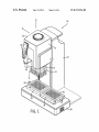
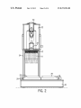
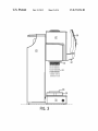
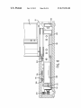
1
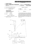
US008372356B2
(12)
United States Patent
Warhurst et a1.
(54)
MANUALLY DIRECTED, MULTI-CHANNEL
ELECTRONIC PIPETTING SYSTEM
(75) Inventors: Julian Warhurst, Ashland, MA (US);
Gary Nelson, Hollis, NH (US); Richard
Cote, Bolton, MA (US)
(73) Assignee: Integra Biosciences Corp., Hudson, NH
(Us)
Notice:
(10) Patent N0.:
(45) Date of Patent:
6,360,792
6,982,063
7,540,205
7,662,343
7,662,344
8,033,188
2005/0249635
2006/0048846
2007/ 0221684
2009/0074622
3/2002
1/2006
6/2009
2/2010
2/2010
10/2011
11/2005
3/2006
9/2007
3/2009
*Feb. 12, 2013
GanZ et al.
Hamel et al.
Nelson et al.
Mathus et al.
Mathus et al.
Kalmakis et al.
Okun et al.
Roenneburg et al.
Steinbrenner et a1.
Kalamakis et al.
(Continued)
Subject to any disclaimer, the term of this
patent is extended or adjusted under 35
U.S.C. 154(b) by 0 days.
B1
B2
B2
B2
B2
B2
A1
A1
A1
A1
US 8,372,356 B2
FOREIGN PATENT DOCUMENTS
WO
This patent is subject to a terminal dis
claimer.
2009/130318
10/2009
OTHER PUBLICATIONS
Rainin Pipetting 360° Simultaneous 96-Well pipetting, Fast manual
(21) Appl. N0.: 13/099,782
benchtop system, 2009 Rainin Instrument, LLc, PB-210 LIQ RevB,
2 pgs.
(22) Filed:
May 3, 2011
(Continued)
(65)
Prior Publication Data
US 2011/0268627 A1
Nov. 3, 2011
Related US. Application Data
Primary Examiner * Brian R Gordon
(74) Attorney, Agent, or Firm *Andrus, Sceales, Starke &
SaWall, LLP
(60) Provisional application No. 61/330,541, ?led on May
3, 2010.
(51)
(57)
Int. Cl.
A manually directed, multi-channel electronic pipetting sys
B01L 3/02
(52)
(2006.01)
tem is designed to transfer liquids from a standard multi-Well
US. Cl. ...... .. 422/509; 422/511; 422/516; 422/522;
422/524; 422/525; 73/863.32; 73/864; 73/864.01;
(58)
ABSTRACT
plate, deep-Well plate or reservoir into another multi-Well
plate. The preferred pipetting head includes an array of 96-tip
73/864.11; 73/864.24; 73/864.25
?ttings. A deck With at least one but preferably tWo or more
Field of Classi?cation Search ................ .. 422/ 509,
Wellplate nesting receptacles holds one or more multi-Well
plates or reagent reservoirs for access by an array of dispos
422/511, 516, 5194522, 5244525, 63468.7;
73/863.32, 864, 864.01, 864.11, 864.13,
73/864.16*864.21, 864.25, 864.31
See application ?le for complete search history.
(56)
able pipette tips mounted to the pipetting head. The electronic
motion control system includes a control handle that is
mounted to a load cell, the carriage for the pipetting head and
is held in the palm of the user. In use, the user grasps the
control handle and operates the system in a manner similar to
one using a handheld electronic pipettor.
References Cited
U.S. PATENT DOCUMENTS
4,478,094 A *
5,116,180 A
10/1984
Salomaa et al.
5/1992 Fung et al.
......... .. 73/863.32
23 Claims, 14 Drawing Sheets
US 8,372,356 B2
Page 2
US. PATENT DOCUMENTS
2009/0274587 A1
2011/0209564 A1 *
11/2009 ButZ et al.
9/2011 Von Beichmann
et al.
2011/0268628 A1
2011/0296931 A1
........................ .. 73/86401
11/2011 Warhurst
12/2011 Warhurst
OTHER PUBLICATIONS
CyBiiWeH Pipettor User Manual, Release Sep. 2008, 88 pgs.
Thermo Scienti?c Matrix Hydra II, Product Speci?cation, 2008
Thermo Fisher Scienti?c, Inc., 2 pgs.
Thermo Scienti?c Matrix PlateMate 2x3, Product Speci?cation,
2007 Thermo Fisher Scienti?c, Inc., 2 pgs.
Thermo Scienti?c Matrix PlateMate Plus, Product Speci?cation,
2007 Thermo Fisher Scienti?c, Inc., 2 pgs.
Rainin Pipetting 360° Liquidator 96, Manual benchtop pipetting
system, 2008 Rainin Instrument, LLC, 9920-360 Rev. B, 16 pgs.
* cited by examiner
US. Patent
Feb. 12, 2013
Sheet 1 0f 14
US 8,372,356 B2
US. Patent
Feb. 12, 2013
30
24
Sheet 2 0f 14
US 8,372,356 B2
US. Patent
Feb. 12, 2013
Sheet 3 0f 14
US 8,372,356 B2
30
12
liiiiiiiiiiiiiil
iii i i i i i K14
HHHHHHHH
iiiiiiiiii'li'iiii'
ii ij ij ij ij ij ijij
32
US. Patent
Feb. 12, 2013
Sheet 4 0f 14
US 8,372,356 B2
US. Patent
Feb. 12, 2013
Sheet 5 0f 14
US 8,372,356 B2
US. Patent
Feb. 12, 2013
Sheet 7 0f 14
US 8,372,356 B2
US. Patent
Feb. 12, 2013
Sheet 8 0f 14
US 8,372,356 B2
m2
wm
US. Patent
Feb. 12, 2013
Sheet 9 0114
US 8,372,356 B2
124
O
102
100
124
12298112114
108
100
91 12412
120
108
98
102
US. Patent
Feb. 12, 2013
Sheet 10 0f 14
US 8,372,356 B2
30
22
_/1
|6
2/
Q
04 6
._ l
/\.Vv/;=z
:L
r__,
,__L
,__,
,/8
77
O0416
(O_n
:LK
2:.\I
1
\IO
2
_n;l"7
\
US. Patent
Feb. 12, 2013
Sheet 11 0114
FIG. 12
_
_
_
_
_
_
_
_
_
1
US 8,372,356 B2
US. Patent
Feb. 12, 2013
Sheet 12 0f 14
24
FIG. 13
US 8,372,356 B2
US. Patent
Feb. 12, 2013
Sheet 14 0f 14
US 8,372,356 B2
[-210
218
FIG. 15
US 8,372,356 B2
1
2
MANUALLY DIRECTED, MULTI-CHANNEL
mated liquid handling systems can also be con?gured to do
ELECTRONIC PIPETTING SYSTEM
quite complex pipetting operations, such as mixing, repeat
pipetting, diluting, etc.
While programmable, automated liquid handling systems
FIELD OF THE INVENTION
have many desirable features over a fully manual 96-Well
liquid transfer system, they are generally too large and expen
sive for use in certain laboratory applications. Therefore, in
many applications, laboratory technicians are resigned to
using multi-channel hand-held pipettors, Which may be quite
The invention relates to a manually directed, multi-channel
electronic pipetting system Which includes a multi-channel
pipetting head having a plurality of pipetting channels
arranged in an array or roWs and columns.
time-consuming.
BACKGROUND OF THE INVENTION
SUMMARY OF THE INVENTION
Multi-Well plates, also knoWn as microtiter plates or
microWell plates, are standard products in clinical and
research laboratories. A multi-Well plate is a ?at plate With
The invention is a manually directed, multi-channel elec
tronic pipetting system for transferring ?uids from a standard
multi-Well plate, a deep-Well plate, a rack of sample tubes or
a reservoir into another multi-Well plate. The term Wellplate
as used herein refers to both standard Well-plates and deep
multiple Wells used as individual test tubes. The most com
mon multi-Well plates include 96-Wells or 384-Wells arranged
in a rectangular matrix. ANSI has set standardiZed dimen
Well-plates.
sions and SBS footprints for Well-plates. For example, a
96-Well plate has 8 roWs and 12 columns of Wells centered 9
20
millimeters centerline-to-centerline. A typical 384-Well plate
includes 16 roWs and 24 columns of Wells With a centerline
to-centerline distance of 4.5 millimeters. Multi-Well plates
With 1536 Wells and higher are also available. Some multi
Well plates are designed to hold larger volumes than a stan
dard multi-channel plate yet maintain the standard centerline
25
to-centerline dimensions. These Well-plates are taller and are
commonly called deep Well-plates.
In the laboratory, multi-Well plates are ?lled With various
liquid samples, and it is routine to transfer liquid samples
An electronic multi-channel pipetting system constructed
in accordance With the invention includes a multi-channel
pipetting head in Which the channels are arranged in a tWo
dimensional array of roWs and columns. In the exemplary
30
embodiment, the pipetting head includes an array of 96-tip
?ttings corresponding to an array of 96-channels. A pipetting
motor is contained Within a carriage for the pipetting head,
and drives the pipetting head to aspirate and dispense. Dis
posable pipette tips are mounted onto the array of tip ?ttings
in order to transfer liquid samples or reagents from one multi
Well plate or reservoir to another multi-Well plate. Alterna
tively, the pipette tips can be mounted using a magaZine.
from one multi-Well plate to another in order to implement
assays or store duplicate samples. It is also routine to transfer
Wells in a Wellplate and transfer aliquots into another set of
The system includes a deck With at least one, but preferably
tWo or more Wellplate nesting receptacles for holding a multi
Well plate or a reagent reservoir. The system also includes a
control handle. Preferably, the control handle is mounted to
the carriage for the pipetting head, and resembles a handle for
a hand-held electronic pipettor. The preferred control handle
Wells on the same Wellplate or another Wellplate. In order to
is the same or quite similar to that disclosed in US. Pat. No.
liquid reagents or samples from a common reservoir to either
a standard multi-Well plate or a deep Well-plate. In some
cases, hand-held, multi-channel pipettes, for example 8 or 12
35
channels, are used to draW some or all the liquid from a set of
produce a high volume of prepared multi-Well plates, auto
mated liquid handling machines have been developed to pro
40
vide much higher throughput than a technician, even With a
multi-channel pipettor. In the art, there are several types of
automated liquid handling machines to automatically ?ll
multi-Well plates. Such automated liquid handling machines
typically use sophisticated Cartesian robots for positioning
syringes and/or pipette tips, as Well as shuttling Well-plates
from storage and into position for liquid transfer. Most of
Richard Cote, ?led on Sep. 17, 2007, assigned to the assignee
of the present application and incorporated herein by refer
ence. The control handle is preferably mounted to a load cell
45
that is attached to a carriage for the pipetting head. The load
50
cell detects force exerted on the control handle When a user
exerts pres sure on the handle and outputs a corresponding
signal to an electronic motor control system. In use, the user
grasps the control handle in a manner similar as When using a
hand-held electronic pipettor, and exerts pressure on the con
these automated liquid handling machines are rather expen
sive, and also quite large. Many include sophisticated com
puter control Which requires extensive training, as Well as
setup and programming.
trol handle to move the pipetting head With respect to the
Well-plates or reservoirs on the deck. The load cell preferably
includes a plurality of strain gauges to detect the direction and
Such automated high-throughput systems are not practical
for some applications. In order to address this need, the prior
art also includes a simultaneous 96-Well manual pipetting
system sold under the trade name Liquidator 96. This fully
manual system includes an array of pipette tip ?ttings match
ing the dimensions of a standard 96-Well plate. Disposable
pipette tips are mounted to the 96-?ttings. The system aspi
rates and dispenses liquid from the 96-pipette tips simulta
neously. Because the system is fully manual, it lacks the
ability to program precise protocols and liquid transfer
amount of force that the user exerts on the control handle. The
55
control system moves the multi-channel pipetting head With
respect to the deck, accordingly, so that the user can align the
pipette tips With the appropriate Wellplate or reservoir on the
deck.
60
is mounted to a toWer that contains a motorized, vertical drive
In the exemplary embodiment of the invention, the carriage
mechanism for raising and loWering the pipetting head With
respect to the Wellplate deck. A motoriZed, horizontal drive
mechanism moves the toWer and the pipetting head laterally
amounts. For example, an electronic hand-held pipettor, or an
automated liquid handling system, can be programmed to
aspirate a precise volume of liquid reagent or sample and then
dispense the aspirated volume, sometimes as a series of
7,540,205 issued Jun. 2, 2009, entitled “Electronic Pipettor”,
application Ser. No. 11/856,231 by Gary E. Nelson, George P.
Kalmakis, Kenneth Steiner, Joel Novak, Jonathon Finger, and
65
in response to the sensed lateral force exerted on the control
handle. For example, if the user presses on the control handle
equal-volume aliquots in successive dispensing operations.
from left to right, the toWer along With the pipetting head
Programmable electronic hand-held pipettors as Well as auto
moves from left to right. If the user pulls upWard on the
US 8,372,356 B2
3
4
control handle, or pushes downward on the control handle,
the vertical drive mechanism raises or loWers the pipetting
head accordingly. The speed of the tWo-dimensional move
ment of the pipetting head (i.e., x-axis and z-axis) is con
stripping plate to eject the disposable pipette tips from the tip
?ttings. The use of the stepped stripping plate enables groups
of tips to be sequentially removed from the tip ?ttings,
thereby reducing the instantaneous torque load on the motor.
In a preferred embodiment, menu-driven softWare displayed
trolled by the electronic motion control system. Preferably,
the speed is normally in proportion to the amount of force
detected by the load cell, hoWever, the electronic motion
control system decelerates the pipetting head as it approaches
on a user interface on the control handle provides an ejection
con?rmation inquiry after the ejector button is activated but
prior to transmitting the control signal to strip the pipette tips.
mechanical displacement limits. As an alternative to moving
the toWer and the pipetting head laterally in response to the
detected force exerted on the control handle, it is possible
In another embodiment of the invention, the system is
designed to hold only one multi-Well plate or reservoir on the
deck. In this embodiment, the system does not require a
Within the spirit of the invention to maintain the toWer in a
?xed lateral position and move the deck laterally to the left or
right in response to the user’s use of the control handle.
horizontal drive mechanism, and the pipetting head does not
move laterally With respect to the deck. The vertical drive
mechanism, hoWever, moves the pipetting head vertically
As mentioned, the control handle is preferably similar to
that disclosed in the above-incorporated US. Pat. No. 7,540,
205 entitled “Electronic Pipettor”. The control handle there
fore preferably includes an elongated body adapted to be held
in the hand of the user. On its front side, it has a touch Wheel
control that is operated by the user, as Well as a dot matrix user
upWard and doWnWard in response to upWard and doWnWard
pressure exerted on the control handle. In this embodiment,
the user needs to place and remove individual multi-Well
plates and/reservoirs from the receptacle nests on the deck. In
20
interface display, Which is located above the touch Wheel
control. The preferred system also includes several micropro
cessors. In an exemplary embodiment of the invention, one of
the microprocessors is located Within the control handle,
although locating a microprocessor in the control handle is
25
another similar embodiment, the lateral position of the deck
With respect to the pipetting head can be moved manually.
In yet another embodiment, the pipetting head is able to
move laterally in a direction perpendicular to the X-direction,
for example by including a Y-axis drive mechanism Which is
responsive to the control handle. In this embodiment of the
not necessary to carry out the invention. The preferred system
invention, it is preferred that the carriage for the pipetting
includes menu-driven softWare for controlling the informa
head be mounted to a gantry rather than to a toWer. One of the
tion displayed on the user interface display and for program
ming the one or more microprocessors that operate the sys
tem. A circular touch pad in the touch Wheel control translates
rotational movement of the user’s thumb or ?nger into cursor
movements on the display in order to navigate the menu
advantages of this embodiment of the invention is that alloWs
access to tWo roWs of Well-plates on the deck. Another advan
30
pipette tips in the Y-axis direction, Which is helpful When
dispensing into 384-Well plates.
driven softWare. The menu-driven softWare is, in many
respects, similar to the softWare disclosed in application
entitled “Pipettor SoftWare Interface”, application Ser. No.
tage is that it alloWs motorized, accurate positioning of the
35
11/856,232 by Gary Nelson, George P. Kalmakis, Gregory
Mathus, Joel Novak, Kenneth Steiner and Jonathon Finger,
If desired, the X-axis lateral drive, or the combination of
the X-axis and Y-axis horizontal drives can be replaced by a
rotational axis horizontal, and perhaps With a radial extender
drive.
In still another embodiment, relative vertical and horizon
?led Sep. 17, 2007, now US. Pat. No. 8,033,188, issued Oct.
tal, or vertical only, motion betWeen the carriage and pipetting
11, 2011, assigned to the assignee of the present application
and incorporated herein by reference. For example, the soft
Ware provides graphic displays for adjusting volume, relative
pipetting speed, pace and count for the various programmed
pipetting procedures. The softWare also preferably provides
multiple programmable pipetting modes based on predeter
mined algorithms such as pipette, repeat pipette, sample
dilute, pipette/mix, manual pipette, reverse pipette, variable
dispense, variable aspirate, sample dilute/mix, and serial dilu
head on the one hand and the deck on the other hand is
40
implemented in a manual fashion. In this embodiment, the
pipetting is still implemented in an electronic fashion, and is
preferably controlled by using a user interface on a control
handle. Other advantages and modi?cations to the invention
may be apparent to those of ordinary skill in the art upon
45
revieWing the folloWing draWings and description thereof.
BRIEF DESCRIPTION OF THE DRAWINGS
tion. These functional modes are based on predetermined
algorithms embedded in the softWare to implement respec
tive, Well knoWn pipetting procedures, although various
50
parameters such as volume, speed, pace, count, direction, and
mixing are available for programming and editing for the
FIG. 2 is a front elevational vieW of the multi-channel
pipetting system illustrated in FIG. 1.
user. In addition, the preferred softWare includes a custom
programming mode in Which the user can create custom
pipetting procedures based on the steps of aspirating, mixing,
dispensing and purging. The preferred softWare also includes
55
Another aspect of the invention is directed to the tip ej ec
tion mechanism. Preferably, an ejector button is located on
60
channel, hand-held pipettor. A sensor on the control handle
detects that the ejector button has been activated and relays a
signal to an electronic control system to activate an automated
tip stripping mechanism on the multi-Well pipetting head.
Preferably, the same motor responsible for moving the pis
tons on the pipetting head to aspirate and dispense is driven
into an over-extended condition in order to move a stepped
FIG. 3 is a side elevational vieW of the manually directed,
multi-channel electronic pipetting system illustrated in FIGS.
1 and 2.
FIG. 4 is a vieW similar to FIG. 1 illustrating tip attachment.
FIG. 5 is a vieW of the control handle and its attachment to
other features as Well.
the control handle similar as in a single-channel or multi
FIG. 1 is a perspective vieW of a manually directed, multi
channel electronic pipetting system constructed in accor
dance With an exemplary embodiment of the invention.
a load cell and carriage in manually directed, multi-channel
electronic pipetting system shoWn in FIGS. 1-4.
FIG. 6 is a loWer perspective vieW of the pipetting head and
pipetting motor a vieW of the manually directed, multi-chan
nel electronic pipetting system shoWn in FIGS. 1-5.
FIG. 7 is a rear loWer perspective vieW illustrating internal
65
components of the manually directed electronic multi-chan
nel pipetting system illustrated in FIGS. 1-6.
FIG. 8 is a vieW taken along line 8-8 in FIG. 7.
US 8,372,356 B2
5
6
FIG. 9 is a sectional view taken along line 9-9 in FIG. 7.
FIG. 9 illustrates the tower being in the left hand side recep
head because of alignment and weight issues. It would be
extremely dif?cult to properly align all 96-pipette tips with a
detached handheld pipettor. Both linear alignment and angu
lar alignment errors would make such a system impractical.
Moreover, such a system would be relatively heavy, perhaps
tacle position.
FIG. 10 is a view similar to FIG. 9 illustrating the tower in
the right hand side receptacle position.
5-10 lbs., which is also impractical. The manually directed,
FIG. 11 is a side elevational view schematically illustrating
the Z-axis vertical drive mechanism in the tower.
FIG. 12 is a detailed view taken along line 12-12 in FIG. 11.
FIG. 13 is a detailed view taken along line 13-13 in FIG. 12.
FIG. 14 is a block diagram illustrating electromechanical
and software control loop used in accordance with one
embodiment of the invention.
FIG. 15 illustrates another embodiment of the invention in
multi-channel electronic pipetting system 10 illustrated in
FIGS. 1-14, provides reliable mechanical alignment of the
pipette tips 14, and also isolates the user from the actual
weight of the pipettor.
The carriage 22 and tower 24 mechanically support the
pipetting head 12 and allow movement of the pipetting head
12 along the vertical Z-axis and the horiZontal X-axis, but
prevent unwanted Y-axis motion or rotation. Other mechani
cal arrangements could be used in accordance with the inven
tion to support and move the pipetting head in a similar
fashion, such as a gantry system, although the tower 24 and
which the manually directed, multi-channel electronic pipet
ting system is designed to hold only one multi-well plate or
reservoir on the deck.
carriage 22 mechanism have been found to be practical.
DETAILED DESCRIPTION OF THE DRAWINGS
The manually directed, multi-channel electronic pipetting
A ?rst embodiment of a manually directed, multi-channel
electronic pipetting system 10 constructed in accordance with
the invention is illustrated in FIGS. 1-14. Referring to FIGS.
20
1 -3, the manually directed, multi-channel electronic pipetting
system 10 includes a multi-channel pipetting head 12 having
a plurality of pipetting channels arranged in a two dimen
sional array of rows and columns. Normally the pipetting
head 12 will include an array of 96-tip ?ttings. An array of
pipette tips 14 are attached to the multi-channel pipetting
head 12. The manually directed, multi-channel electronic
pipetting system 10 includes a ?at deck 16 supporting a right
nesting receptacle 18 and a left nesting receptacle 20. The
tips. FIG. 4 illustrates a box 34 of pipette tips located on the
25
magaZine. The preferred tip attachment and ejection mecha
30
35
The pipetting head 12 is removably mounted to a carriage
the tower 24 and the deck 16. An X-axis drive mechanism
moves the tower 24 and the carriage 22 horizontally along an
X-axis so that the pipetting head 12 and the array of tips 14
can be moved from a position corresponding to the wellplate
26 in the ?rst nesting receptacle 18 on the deck 16 to positions
application and incorporated herein by reference. Brie?y, the
40
45
corresponding to the wellplate 28 residing in the left side
nesting receptacle 20.
The system 10 includes a control handle 30 preferably
mounted to the carriage 22 and as mentioned previously and
preferably resembles a handle for a handheld electronic pipet
tor. More speci?cally, the control handle 30 is preferably
mounted to a load cell 32 that is attached to the carriage 22. In
use, the user grasps the control handle 30 in the manner
similar as when using a handheld pipettor, and exerts pres sure
on the control handle 30 to move the carriage 22 and the
55
quite di?icult; however, motion control software facilitates
Electromechanical and software controls motion of the
60
ment, and control force exerted by the drive systems, etc.
General aspects of the motion control system are described
below in connection with FIG. 14. Preferably, biasing soft
ware as disclosed in patent application “Pipette Tip Position
ing for Manually-Directed, Multi-Channel Electronic Pipet
overall operation of the system 10 is intended to replicate the
user would not be able to reliably use a 96-channel pipetting
motion of the carriage 22 and pipetting head 12 is controlled
by the user by holding the controller 30 in their palm and
applying pressure in the appropriate direction to position the
pipetting head 12 over the tray 34 of pipette tips 14. Precise
alignment necessary for tip attachment would of course be
pipetting head and smooth operation, foster precise align
discussed in more detail below.
As mentioned, the use of the controller 30 as well as the
pipettor. However, with a conventional handheld pipettor, a
driven mechanism. Then, the Z-axis vertical drive mechanism
is used to lower the carriage 22 and the tip ?ttings 36 with
suf?cient force to attach the array of pipette tips 14. The
carriage 22 and the pipetting head 12 are then raised using the
Z-axis horiZontal vertical drive mechanism to remove the tips
14 from the tip container 34. The tip container 34 is removed
from the nested receptacle 18 and replaced with a wellplate or
reservoir in order to transfer ?uids. For tip attachment as with
precise alignment.
servo control as is explained below. The control handle 30
natural hand motion of a user using a conventional handheld
pipetting head 12 with the array of tip ?ttings 36 is aligned
precisely over the tip container 34 using the X-axis horiZontal
regular motion control, the general horiZontal and vertical
50
pipetting head 12. The vertical Z-axis motion and the hori
Zontal X-axis motion are driven by independent motors under
also preferably includes a user interface for controlling pipet
ting functions such as aspirating and dispensing as is also
nism is disclosed in detail in patent application entitled
“Unintended Motion Control for Manually Directed Multi
Well Electronic Pipettor” ?led on even date herewith by
Julian Warhurst and Richard Cote, claiming priority to US.
Provisional Patent Application No. 61/330,545, ?led on May
3, 2010, now US. patent application Ser. No. 13/099,953,
?led May 3, 2011, Publication No. US 2011/0268628, pub
lished Nov. 3, 2011, assigned to the assignee of the present
22 which in turn is mounted to a tower 24. A pipetting motor
located within the carriage 22 drives the multi-channel pipet
ting head 12 to aspirate and dispense. As described in more
detail below, a Z-axis drive mechanism moves the carriage 22
and the multi-channel pipetting 12 vertically with respect to
right side nesting receptacle 18 ready for attachment to the
pipetting head 12. The preferred pipetting head includes an
array of 96-tip ?ttings, see eg reference number 36 in FIG. 6.
However, other ways known in the art to mount tips can be
used in accordance with the invention, such as using the
nesting receptacles 18, 20 are designed to hold multi-well
plates, racks of storage tubes or reservoirs in a known location
on the deck 16. The nesting receptacles 18, 20 can be attached
to the deck 16 or can be made integral with the deck 16.
system 10 must not only be capable of transferring ?uids from
and to selected locations, but must also provide for the prac
tical and convenient attachment and ejection of the pipette
65
tor”, by Julian Warhurst, ?led on even date herewith, claiming
priority to US. Provisional Patent Application No. 61/330,
551, ?led on May 3, 2010, now US. patent application Ser.
No. 13/099,854, ?led May 3, 201 1, Publication No. US 2011/
US 8,372,356 B2
7
8
0296931, published Dec. 8, 2011, and assigned to the
assignee of the present application and incorporated herein by
reference is used to facilitate appropriate horizontal align
ment of the pipetting head 12 for tip attachment. In addition,
including an additional main microprocessor. The circular
touchpad 52 translates rotational movement of the user’s
thumb (or ?nger) into cursor movements on the display 54 in
order to navigate menu driven softWare. The menu driven
the system 10 also preferably includes softWare checks to
assure proper alignment of the pipetting head before imple
menting tip attachment functions, as disclosed in the above
closed in application entitled “Pipettor SoftWare Interface”,
application Ser. No. 11/856,232 by George Kalmakis et al.,
softWare is, in many respects, similar to the softWare dis
incorporated patent application entitled “Unintended Motion
?led Sep. 17, 2007, noW U.S. Pat. No. 8,033,188 issued Oct.
Control for Manually Directed Multi-Channel Electronic
Pipettor”. Brie?y, the amount of doWnWard force necessary
for tip attachment is substantially greater than the amount of
11, 2011, assigned to the assignee of the present application
and incorporated herein by reference. As mentioned previ
doWnWard force desirable during normal operation. AlloWing
volume, relative pipetting speed, pace and count for the vari
ous program pipetting procedures. The softWare also prefer
ously, the softWare provides graphic displays for adjusting
pipette tips to crash into Well-plates With too much force can
cause damage, as Well as loss of reagents and samples and the
like. The system 10 preferably includes a tip attach button 38
on top of the carriage 22 Which must be depressed in order for
the system 10 to exert suf?cient doWnWard vertical force for
tip attachment. For example, the user Will depress a button 38
With their left hand and hold the controller 30 in their right
hand and push doWn on the controller 30 in order to move the
ably provides multiple programmable pipetting modes based
on predetermined algorithms, such as pipette, repeat pipette,
sample dilute, pipette/mix, manual pipette, reverse pipette,
variable dispense, variable aspirate, sample dilute/mix, and
serial dilution. These functional modes are based upon pre
determined algorithms embedded in the softWare to imple
20
carriage 22 doWnWard to attach the tips to the pipetting head
12. The tip attachment button 38 need not be located on the
top of the carriage 22, although it is desirable to occupy both
hands of the user for safety purposes. For example, it may be
desirable to place the tip attachment button 38 at a different
location on the system 10, or on the surface of the laboratory
Workbench.
ment respective, Well knoWn pipetting procedures, although
various parameters such as volume, speed, pace, count, direc
tion and mixing are available for programming and editing for
the user. In addition, the preferred softWare also includes a
custom programming mode in Which the user can create
25
custom pipetting procedures based on the steps of aspirating,
mixing, dispensing and purging. The preferred softWare also
includes other features as Well.
After samples and/or reagents have been pipetted, the tips
While the touch Wheel control 52 and the display 54 are
are typically ejected into a tip tray 34 or loosely into a bin.
Referring noW to FIG. 5, the control handle 30 is attached to
generally used to program the pipetting system, the display 54
30
a cantilever 40 on the load cell 32. The cantilever 40 extends
generally horizontally forward from a base 42 of the load cell
32 that is attached to the frame of the carriage 22. A pair of
strain gauges 44 is attached to a top surface of the load cell
base 42. This pair 44 of strain gauges is used to detect the
amount of force or pressure applied by the control handle 30
on the load cell 32 in the X-axis horiZontal direction. Another
pair of strain gauges 46 is attached to a sideWall of the base 42
of the load cell 32. This pair of strain gauges 46 is used to
detect the amount of force or pressure that the control handle
30 exerts in the vertical Z-axis direction on the load cell 32.
The X-axis drive and the Z-axis drive operate independently
and contemporaneously When a component of force input is
measured by each respective pair of strain gauges 46. Elec
trical leads 48 connect the strain gauges 44, 46 to input
terminals 50 located Within the carriage 22. The terminals 50
provide electrical connection to the motion control system
Which is schematically illustrated in FIG. 14, and are prefer
ably located on a printed circuit board Within the carriage 22.
As mentioned, the preferred control handle 30 is the same
With the pipetting protocol on the display 54. For example,
35
consider a situation in Which the pipette tips 14 are attached to
the pipetting head 12 ready for use and a reagent reservoir is
40
placed Within nested receptacle 18 and a Wellplate With
samples is placed in nested receptacle 20, and it is desirable in
accordance With a programmed protocol to transfer 20 ml of
the reagent from the reservoir into each of the 96-Wells in the
Well-plate. The user grasping the control handle 30 Will ?rst
direct the carriage 22, pipetting head 12 and pipette tips 14
45
50
7,540,205 entitled “Electronic Pipettor” by Gary Nelson et al.
issued on Jun. 2, 2009, Which is incorporated herein by ref
erence. The preferred control handle 30 not only provides a
55
of the pipetting head, but also preferably provides a user input
nesting receptacle 20, and align the pipette tips over the
appropriate Wells in the Wellplate by pressing against the
stepper motor to dispense the liquid in the pipette tips.
elongated body adapted to be held in the hand of the user. A
touch Wheel control 52 is designed to be operated by the
Referring to FIG. 6, a stepper motor 57 drives an array of
60
pistons in the pipetting head 12 to aspirate and dispense. The
65
invention is not limited to the type of pipetting motor and
accompanying multi-channel manifold as systems other than
the type shoWn can be used in accordance With the invention.
Preferably, the pipetting motor is an electronically controlled
stepper motor similar to that disclosed in co-pending U. S. Pat.
dot matrix user interface display 54. The preferred controller
30 also includes a run button 56 Which is located beloW the
touch Wheel control 52 and an ejector button 58. In this
exemplary embodiment, a printed circuit board With a dedi
cated microprocessor is located Within the control handle 30,
although the toWer 24 contains a larger main printed circuit
board containing several mounted electronic components
from the reagent reservoir in the ?rst nesting receptacle 18 by
control handle 30. The user Will then loWer the ?lled tips over
the Wells, and presses run button 56 to instruct the pipettor
interface. The control handle 30 shoWn in FIG. 5 includes an
user’s thumb. The touch Wheel control 52 is located beloW a
over the reservoir located in nesting receptacle 18. The dis
play 54 may illustrate an instruction such as “aspirate 20 ml”.
The user Will then loWer the pipette tips 14 into the liquid in
the reservoir by placing doWnWard pressure on the control
handle 30. Then, in order to aspirate 20 ml of the reagent into
each pipette tip 14, the user Will press run button 56 to activate
the pipetting stepper motor to aspirate 20 ml of reagent into
each pipette tip. The user Will then lift the ?lled pipette tips 14
pulling upWard on the control handle 30. The next instruction
on the display 54 may be “dispense 20 ml”. The user Will then
move the ?lled pipette tips over the Wellplate in the second
or quite similar to that disclosed in issued U.S. Pat. No.
handle for attachment to the load cell 32 to control movement
is also used to shoW progress or status during an implemented
pipetting routine. In this regard, the run button 56 is used to
activate the system to aspirate or dispense, etc. in accordance
No. 7,540,205, assigned to the assignee of the present appli
cation and incorporated herein by reference. It is desirable