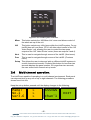
1
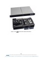
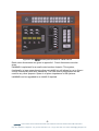
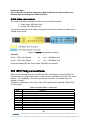
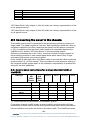
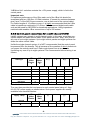
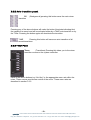
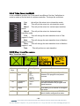
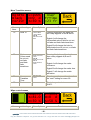
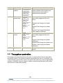
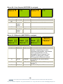
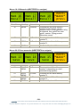
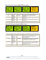
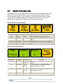
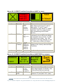
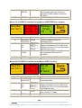
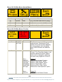
eyeheight
irisHDi series
HD-SDI vision mixer. irisHDi, irisHDiOB
12/10/06 v2.10
user manual
Table of Contents
1 System Overview ...............................................................................................4
2 Installation ..........................................................................................................6
2.1
Control Panels. .......................................................................................6
2.2
Main Processing Chassis........................................................................8
2.2.1 Environmental requirements. ...............................................................8
2.2.2 Electrical requirements. .......................................................................8
2.2.3 Video connections................................................................................9
2.3
GPI/Tally connections. ............................................................................9
2.4
Connecting the panel to the chassis. ....................................................10
2.4.1 Control panel connections for a single channel irisHDi or irisOBHDi .10
2.4.2 Control panel connections for a multi channel irisHDi........................11
3 Operation .........................................................................................................12
3.1
Overview. ..............................................................................................12
3.2
Basic Operation. ...................................................................................12
3.2.1 Program/preset bus. ..........................................................................12
3.2.2 Auto transition panel. .........................................................................13
3.2.3 T-Bar Panel........................................................................................13
3.2.4 T-Bar Panel, irisOBHDi ......................................................................14
3.2.5 Mixer transition menus.......................................................................14
3.3
The system controller............................................................................16
3.4
Multi channel operation. ........................................................................17
3.5
Automation control. ...............................................................................19
3.6
Utility menus. ........................................................................................19
3.7
Mixer Full menu set...............................................................................24
4 Appendices ......................................................................................................33
4.1
Appendix 1, irisHDi cut-out panel dimensions.......................................33
4.2
Appendix 2, irisOBHDi cut-out panel dimensions.................................34
4.3
Appendix 3, irisHDi tub (TB-10) cut-out panel dimensions....................35
4.4
Appendix 4, irisHDi technical specification............................................35
4.4.1 irisHDi. ...............................................................................................35
4.4.2 irisOBHDi ...........................................................................................36
-2eyeheight Unit 34 Park House Watford Business Park Greenhill Crescent Watford Herts GB WD18 8PH
Reg. No. 2855535 Telephone: +44 (0) 1923 256 000 Fax: +44 (0) 1923 256 100 email: [email protected]
Table of Figures
Figure 1-1 The irisHDi system which requires 1RU chassis .................................5
Figure 2-1 The irisHDi Control panel in optional extra Tub ...................................6
Figure 2-2 The irisHDi Control panel mounted in a desk cut-out ..........................7
Figure 2-3 irisOBHDi panel in a desk cut-out ........................................................8
Figure 2-4 irisHDi main processor chassis............................................................9
Figure 3-1 The irisHDi system control panel .......................................................12
Figure 3-2 The irisHDi system controller .............................................................17
Figure 4-1 irisHDi Desk cut-out dimensions ........................................................33
Figure 4-2 irisOBHDi suggested desk cutout dimensions ..................................34
Figure 4-3 irisHDi tub (IT-9) fixing dimensions ....................................................35
-3eyeheight Unit 34 Park House Watford Business Park Greenhill Crescent Watford Herts GB WD18 8PH
Reg. No. 2855535 Telephone: +44 (0) 1923 256 000 Fax: +44 (0) 1923 256 100 email: [email protected]
1 System Overview
The “irisHDi” is a small HD-SDI vision mixer. There are two versions of this
unit.
1. irisHDi: This is an 8 input HD-SDI mixer with a processor module
consisting of two evolution chassis mounted together, one is the ‘A/B
Mixer Unit’ and the other the ‘HD Video Router’. There is also a small
control panel consisting of a program-preset bus, a system controller, a
T-bar, and an auto transition panel. This system is multi channel
capable. The basic irisHDi fits into a 1RU chassis.
2. irisOBHDi : This is an 8 input HD-SDI mixer with a processor module
consisting of two evolution chassis mounted together, one is the ‘A/B
Mixer Unit’ and the other the ‘HD Video Router’. There is also a cutdown control panel consisting of a program-preset bus, and a T-bar
which can be mounted separately to fit into available spaces. This
system operates in single channel mode only. irisOBHDi can be
upgraded to a full irisHDi. irisOBHDi fits into a 1RU chassis.
Full technical details of each version of irisHDi are given in appendix 3 at
the end of this manual.
-4eyeheight Unit 34 Park House Watford Business Park Greenhill Crescent Watford Herts GB WD18 8PH
Reg. No. 2855535 Telephone: +44 (0) 1923 256 000 Fax: +44 (0) 1923 256 100 email: [email protected]
Figure 1-1 The irisHDi system which requires 1RU chassis
-5eyeheight Unit 34 Park House Watford Business Park Greenhill Crescent Watford Herts GB WD18 8PH
Reg. No. 2855535 Telephone: +44 (0) 1923 256 000 Fax: +44 (0) 1923 256 100 email: [email protected]
2 Installation
The irisHDi system comes in two parts, the control panel and the processing
chassis.
2.1 Control Panels.
The control panel is made from four separate modules. These modules either can
be mounted in the eyeheight irisHDi “Tub”, order code TB-10, or can be mounted
in a desk cutout.
Figure 2-1 The irisHDi Control panel in optional extra Tub
-6eyeheight Unit 34 Park House Watford Business Park Greenhill Crescent Watford Herts GB WD18 8PH
Reg. No. 2855535 Telephone: +44 (0) 1923 256 000 Fax: +44 (0) 1923 256 100 email: [email protected]
Figure 2-2 The irisHDi Control panel mounted in a desk cut-out
Desk cutout dimensions are given in appendix 1. Panel dimensions are also
given.
irisOBHDi is optimised for a small control surface footprint. This system,
functionally, is less comprehensive than an irisHDi but still allows for up to 8 input
cut/mix functionality with auto transitions. The free control panel space can be
used for any other purpose. Space is of prime importance in OB systems.
irisOBHDi can be upgraded to an irisHDi if required.
-7eyeheight Unit 34 Park House Watford Business Park Greenhill Crescent Watford Herts GB WD18 8PH
Reg. No. 2855535 Telephone: +44 (0) 1923 256 000 Fax: +44 (0) 1923 256 100 email: [email protected]
Figure 2-3 irisOBHDi panel in a desk cut-out
Desk cutout dimensions are given in appendix 2. Panel dimensions are also
given.
2.2 Main Processing Chassis
2.2.1 Environmental requirements.
The irisHDi and irisOBHDi Processor are a 1RU Chassis.
The unit requires 4 x M5 rack bolts to secure the unit at the front into a 19” rack. It
is necessary that the unit be given support at the rear to minimise stress on front
fixing chassis.
The units should be run in an air-conditioned technical area with an ambient
temperature no greater than 30 C.
2.2.2 Electrical requirements.
An irisHDi system will use less than 50 Watts of power from an electrical supply.
The power supplies are "Wide Range" and will operate from a steady 100Æ240V
ac 47-63 Hz. A clean technical feed is required to ensure "Glitch Free" operation.
Both the evolution chassis in the processor module require mains leads
connected to them.
Each evolution is currently fitted with one live-wired one amp fuse, which is
detachable underneath the IEC inlet. The fuses should only be replaced with
"slow-blow 2 Amp 20mm type".
-8eyeheight Unit 34 Park House Watford Business Park Greenhill Crescent Watford Herts GB WD18 8PH
Reg. No. 2855535 Telephone: +44 (0) 1923 256 000 Fax: +44 (0) 1923 256 100 email: [email protected]
Important Note:
Do not handle any mains equipment with wet hands or remove the cover
without disconnecting the mains feed first.
2.2.3 Video connections.
The main processing chassis consists of two evolution Chassis
1. A two input ‘A/B Mixer Unit’
2. An 8x4 ‘HD Video Router’
The system requires some video connections between the blocks to make up an
irisHDi vision mixer.
Figure 2-4 irisHDi main processor chassis
Connect:
Out A - ‘HD Video Router’
to
In 2 - ‘A/B Mixer Unit’
Out B - ‘HD Video Router’
to
In 3 - ‘A/B Mixer Unit’
Using a suitable HD-SDI video cable with BNC connectors.
2.3 GPI/Tally connections.
Given in the tables below are the GPI and tally connections on the irisHDi. For
Tally out format, refer to the section “Utility menus” and Menu 06 of the ‘HD Video
Router’. For irisOBHDi , which has no system controller, the default tally out
setting is “Integr”.
These are accessible on the rear of the ‘HD Video Router’ labelled “Tallies Out”
(15W D-type).
Table 1 HD Video Router “Tallies Out”
Pin#
1
2
3
4
5
6
7
8
9
10
Function
Tally Output #1 Relay closure.
Tally Output #2 Relay closure.
Tally Output #3 Relay closure
Tally Output #4 Relay closure
Tally Output #5 Relay closure
Tally Output #6 Relay closure
Tally Output #7 Relay closure.
Tally Output #8 Relay closure.
Relay Common Contact
Relay Common Contact
-9eyeheight Unit 34 Park House Watford Business Park Greenhill Crescent Watford Herts GB WD18 8PH
Reg. No. 2855535 Telephone: +44 (0) 1923 256 000 Fax: +44 (0) 1923 256 100 email: [email protected]
11
12
13
14
15
Relay Common Contact
Relay Common Contact
Relay Common Contact
Reserved
Reserved
‘HD Video Router’ tally outputs 1 (lsb)Æ4 (msb) are a binary representation of the
on-air program source.
‘HD Video Router’ tally outputs 5 (lsb)Æ8 (msb) are a binary representation of the
on-air preset source.
2.4 Connecting the panel to the chassis.
The irisHDi control panel is connected to the processing module by means of a
single cable. The cable contains a “two wire” data connection called the I-Bus (or
sometimes called the Can-Bus, these are the same!) and the power connection
(+13V). In addition to this the pins 6 and 8 need to be connected between the
‘A/B Mixer Unit’ and the ‘HD Video Router’ in the processing module.
All these connections are on the ‘I-Bus’ connector of each evolution chassis of
the processing module or each control panel block which have 9 Way D-type
connectors that require connecting together.
Every irisHDi is delivered with a test ribbon cable to connect the I-Bus connectors
as per section 2.4.1 of this manual. This is provided for initial customer testing of
the complete irisHDi system and it is the customer’s responsibility to produce the
wiring for the final installation.
2.4.1 Control panel connections for a single channel irisHDi or
irisOBHDi .
I-Bus function of
9W D-type
HD
Video
Router
FP-10 (*)
A/B
Mixer
Unit
VP-10
TK-10 (*)
PP-10
Ground
1,5
1,5
1,5
1,5
1,5
I-Bus-
2
2
2
2
2
Not Used
-
-
-
-
-
+13V
-
4,9
4,9
4,9
4,9
SD/HD
6
-
-
-
-
I-Bus+
7
7
7
7
7
Ref Pulse
8
-
-
-
-
(*) These units are not provided in an irisOBHDi system.
For a single channel irisHDi system a control cable is requires which will loop
evolution to evolution and on to the control panel where each control panel block
has an individual connection as shown in the above table. The irisHDi processor
- 10 eyeheight Unit 34 Park House Watford Business Park Greenhill Crescent Watford Herts GB WD18 8PH
Reg. No. 2855535 Telephone: +44 (0) 1923 256 000 Fax: +44 (0) 1923 256 100 email: [email protected]
‘A/B Mixer Unit’ evolution contains the +13V power supply, which is fed to the
control panel.
Important note:
For optimum performance of the I-Bus each end of the I-Bus link should be
terminated with two 100 Ohm 1/8 Watt resistors. (Connect the resistors between
pins 2 and 7 of the 9W D-type connector, one at each end of the control cable).
For Cable lengths of 10 meters or more, it is highly recommended that the I-Bus
cable is impedance matched to 110 Ohms. We recommend digital audio cable
such as that used for AES EBU for broadcast applications. Using impedance
matched cable enables I-Bus connections of up to 200 meters.
2.4.2 Control panel connections for a multi channel irisHDi
irisHDi systems can operate in multi channel mode. In this case, more than one
system shares the same control cable. Each panel can then “drop” and “pick-up”
any one of up to eight systems. Up to eight control panels and eight systems can
share the same control cable.
Unlike the single channel system, it is NOT recommended that the control panel
be powered from the chassis. This is because of the question of which chassis do
you power the control panel from? Each control panel can at any time be
controlling any one of up to eight systems! The recommended control wiring is as
follows:
I-Bus function of
9W D-type
HD
Video
Router
A/B
Mixer
Unit
X
X
FP-10
X (*)
VP-10
X
TK-10
X (*)
PP-10
X
round
1,5
1,5
1,5
1,5
1,5
I-Bus-
2
2
2
2
2
Not Used
-
-
-
-
-
+13V
-
-
-
-
-
SD/HD
6
-
-
-
-
I-Bus+
7
7
7
7
7
Ref Pulse
8
-
-
-
-
Note: X=1 to 8
The user then provides the local power to each control panel using a 1 Amp
8Æ12V DC power supply as shown below. Such power supplies are readily
available from electrical dealers.
Local 12V power
supply. 1 Amp
HD
Video
Router
FP-10
(*)
A/B
Mixer
Unit
VP-10
TK-10
(*)
PP-10
Ground
-
1,5
1,5
1,5
1,5
+8Æ+12V
-
4,9
4,9
4,9
4,9
- 11 eyeheight Unit 34 Park House Watford Business Park Greenhill Crescent Watford Herts GB WD18 8PH
Reg. No. 2855535 Telephone: +44 (0) 1923 256 000 Fax: +44 (0) 1923 256 100 email: [email protected]
3 Operation
3.1 Overview.
The operation of the irisHDi mixer is performed using the irisHDi control panel. In
this description irisOBHDi will be described separately.
Figure 3-1 The irisHDi system control panel
Figure 3-1 The irisHDi, left - System control (FP-10), middle – T Bar module (VP10), right - auto transition module (TK-10), top – program/preset panel (PP-10)
3.2 Basic Operation.
The simplest operation of the irisHDi revolves around the use of the
program/preset bus, the T-Bar module and the Auto Transition panel.
3.2.1 Program/preset bus.
The program bus indicates the current “on-air” source. The user selects the next
video source using the preset bus. After a BG (background) transition the
program and preset sources “swap” or “flip-flop” ready to select the next source
for transition. The user can also cut directly on the program bus. This will cause
an instant transition cut to occur to the selected program source.
- 12 eyeheight Unit 34 Park House Watford Business Park Greenhill Crescent Watford Herts GB WD18 8PH
Reg. No. 2855535 Telephone: +44 (0) 1923 256 000 Fax: +44 (0) 1923 256 100 email: [email protected]
3.2.2 Auto transition panel.
BG
transition
(Background) pressing this button arms the main mixer
Pressing any of the above buttons will make the button illuminate indicating that
the transition is armed and will be activated either by a TAKE auto transition or by
the T-Bar. Pressing the button again will deactivate the transition.
TAKE
Pressing this button will cause an auto transition of all
armed transitions.
3.2.3 T-Bar Panel
Trans
(Transitions) Pressing this takes you to the mixer
transition menus on the system controller.
Each of the above buttons is a “Hot Key” to the appropriate menu set within the
mixer. These menus provide fine control of the mixer. These menu sets are
described in section 3.2.5.
- 13 eyeheight Unit 34 Park House Watford Business Park Greenhill Crescent Watford Herts GB WD18 8PH
Reg. No. 2855535 Telephone: +44 (0) 1923 256 000 Fax: +44 (0) 1923 256 100 email: [email protected]
3.2.4 T-Bar Panel, irisOBHDi
In the irisOBHDi product, the T-bar panel has different “Hot key” definitions in
order to make up for the lack of a system controller. The keys are as follows.
Cut,
this will put the mixer into cut transition mode.
Mix
This will put the mixer into mix transition mode.
Wipe1
mode.
This will put the mixer into vertical wipe transition
Wipe2
This will put the mixer into horizontal wipe
transition mode.
Fast
This will change the auto transition time to Fast
(approx 0.3 sec)
Med
This will change the auto transition time to Medium
(approx 0.5 sec)
Slow
This will change the auto transition time to Medium
(approx 1 sec)
Take
This will perform an auto transition.
3.2.5 Mixer transition menus.
Main Transition menu
Menu
Num.
68
Heading
Menu Options
Function
Transition
type
0=mix
1=wipe
2=cut
3=cut-cut
4=cut-fade
5=fade-cut
6=fade-fade
This changes the type of transition
between the program and preset
sources.
69
Transition
Speed
0=fast
1=medium
2=slow
3=user
This changes the speed of the
transition between the program and
preset sources.
70
Wipes
71
More
This takes you to menus to configure
the wipes.
This takes you to menus 72Æ75
which further configure the mixer.
- 14 eyeheight Unit 34 Park House Watford Business Park Greenhill Crescent Watford Herts GB WD18 8PH
Reg. No. 2855535 Telephone: +44 (0) 1923 256 000 Fax: +44 (0) 1923 256 100 email: [email protected]
More Transition menus.
HoldTo
Black
For15F
Menu
Num.
72
L=100%
H=0 d
S=50 %
Heading
User
TrTime
=23 fr
Menu Options
Function
Level A:
0=Hold to Black
1=Hold to Matte
Level B:
Hold Time 0Æ993
Fields
Hold To
Pressing this button will make the
two rotary digipots A and B active:
Digipot A will change the
intermediate colour field for cut-cut,
cut-fade and fade-fade transitions.
Digipot B will change the hold to
black/matte time for cut-cut, cut-fade
and fade-fade transitions.
73
Matte
Colour used
for cut-cut,
cut-fade
and fadefade
transitions.
Level A:
Border Luminance,
0Æ255
Level B:
Border Hue, 0Æ255
Level C:
Border saturation,
0Æ255
Pressing this button will make the
three rotary digipots A,B and C
active:
Digipot A will change the matte
luminance.
Digipot B will change the matte hue.
Digipot C will change the matte
saturation.
74
75
User Tran Time
3Æ253.
User
Transition
Time
Back
This changes the transition time of
the “user” setting for menu 69
This takes you back to menus
68Æ71.
Wipe control menus
NoBord
S=81.0
D=50 %
Menu
Heading
L=100%
H=0 d
S=50 %
Menu Options
Function
- 15 eyeheight Unit 34 Park House Watford Business Park Greenhill Crescent Watford Herts GB WD18 8PH
Reg. No. 2855535 Telephone: +44 (0) 1923 256 000 Fax: +44 (0) 1923 256 100 email: [email protected]
Num.
76
Wipe
pattern
0= vertical wipe
1= horizontal wipe
2=vertical curtain
3=horizontal curtain
4=diagonal wipe
5=diamond wipe
6=horizontal arrow
7=vertical arrow
This changes the type of wipe
pattern between the program and
preset sources when wipe is
selected as the transition.
77
Border
parameters
Level A:
0=No Border
1=Border 1, Hard
Coloured border.
2=Border 2, soft
border edge.
3=Border 3, soft and
coloured border.
Level B:
Border size, 1Æ49
Level C:
Colour Depth,
0Æ511
Pressing this button will make the
three rotary digipots A,B and C
active:
Digipot A will change the border
type.
Digipot B will change the border
size.
Digipot C will change the border
colour depth for Border3.
78
Border
colour
Level A:
Border Luminance,
0Æ255
Level B:
Border Hue, 0Æ255
Level C:
Border saturation,
0Æ255
Pressing this button will make the
three rotary digipots A,B and C
active:
Digipot A will change the border
luminance.
Digipot B will change the border hue.
79
Digipot C will change the border
saturation.
This takes you back to menus
68Æ71.
Back
3.3 The system controller.
The system controller block allows the user to control all the finer set-ups within
the irisHDi system. The system controller also allows the user to use irisHDi in a
“multi-channel” environment, where any panel can control any one of eight irisHDi
systems. irisOBHDi does not have a system controller and therefore has limited
set-up and no multi channel ability.
- 16 eyeheight Unit 34 Park House Watford Business Park Greenhill Crescent Watford Herts GB WD18 8PH
Reg. No. 2855535 Telephone: +44 (0) 1923 256 000 Fax: +44 (0) 1923 256 100 email: [email protected]
Figure 3-2 The irisHDi system controller
Mixer
This button selects the ‘A/B Mixer Unit’ mixer and allows control of
the whole set-up of the unit
Util
This button selects any utility items within the irisHDi system. For an
irisHDi there will one items, UTIL1 will allow direct control of the ‘HD
Video Router’ unit, allowing the user to control the two spare
outputs of the ‘HD Video Router’ router (these are outputs 3 and 4).
Next
This is used to navigate through menus of the irisHDi. (Next menu)
Prev
This is used to navigate through menus of the irisHDi. (Previous
menu)
Setup This allows the user to drop and pick up different irisHDi systems in
a multi channel environment. Pressing this button for less than two
seconds displays the panel number, for longer than two seconds,
the user enters multi channel set-up mode.
3.4
Multi channel operation.
The irisHDi are capable of operating in a multi channel environment. Each panel
can drop and pick up any one of up to eight channels. The following procedure
shows how to do this.
Keep the set-up button pressed until the display changes to the following:
Panel
No.1
Ver3.6
>
>
>
ASSIGN
Chan’1
EXIT
- 17 eyeheight Unit 34 Park House Watford Business Park Greenhill Crescent Watford Herts GB WD18 8PH
Reg. No. 2855535 Telephone: +44 (0) 1923 256 000 Fax: +44 (0) 1923 256 100 email: [email protected]
Press “Assign Chan’l” to continue to multi channel set-up. The display should
look similar to the following:
Iris1
IsWith
Panel1
FREE
EXIT
Chan
In this case, the display invites you to press the “FREE Chan” button. This will
take away control of the channel from this panel. The display will then look like
this:
Iris1
Is
FREE
AQUIRE
Chan
EXIT
To then pick up another channel press the flashing "Next" button. If channel 2 is
available, the display will look like this:
Iris2
Is
Free
AQUIRE
Chan
Exit
If channel 2 is not available, the display may look something like this:
Iris2
Is
Absent
EXIT
If channel 2 is currently under the control of another panel the display may look
something like this:
Iris2
IsWith
Panel4
EXIT
In this case, panel 4 is controlling irisHDi 2. In the case above, that channel 2 is
available, the user is invited to press the “AQUIRE Chan” button after which the
- 18 eyeheight Unit 34 Park House Watford Business Park Greenhill Crescent Watford Herts GB WD18 8PH
Reg. No. 2855535 Telephone: +44 (0) 1923 256 000 Fax: +44 (0) 1923 256 100 email: [email protected]
display will look like this:
Iris2
IsWith
Panel1
FREE
EXIT
Chan
If the user now presses “EXIT”, normal mixer operation resumes.
The above gives the user an idea of how to change channels from a panel. This
example can only show one certain configuration of panels and channels. The
user will need to use this example as a general guide when coming to a system
for the first time.
3.5
Automation control.
The irisHDi vision mixer can be fitted with PresTX automation control. Please
contact eyeheight for further information. At the time of writing Grass Valley
GVG2100 protocol is also planned.
3.6
Utility menus.
The irisHDi have a set of up to 4 utility product menus. These are activated by
pressing the “UTIL” button and selecting the UTIL 1Æ4 options. For an irisHDi,
“AuxBus Util 1” allows access to the menus of the program/preset crosspoints,
the ‘HD Video Router’. This allows the user to override the program/preset bus
(not recommended) but also allows the user to control the spare outputs of the
router Aux1 and Aux2. The menu set of the ‘HD Video Router’ is as follows:
Menus 00-03 Top Level Menus (Press next to navigate)
A
OP
=1
Menu Num.
00
01
02
B
OP
=2
Heading
Program
output
select
Preset
output
select
Aux 1
output
Automation
1Æ8
1Æ8
1Æ8
Aux1OP
Aux2OP
=1
=1
Function
Selects the current on-air program
output. CAUTION!!! This will over-ride
the program bus selector.
Selects the current preset bus source.
CAUTION!!! This will over-ride the
preset bus selector.
Selects the current Aux 1 bus source.
- 19 eyeheight Unit 34 Park House Watford Business Park Greenhill Crescent Watford Herts GB WD18 8PH
Reg. No. 2855535 Telephone: +44 (0) 1923 256 000 Fax: +44 (0) 1923 256 100 email: [email protected]
03
select
Aux 2
output
select
1Æ8
Selects the current Aux 2 bus source.
Menus 04-07 ‘HD Video Router’ set-up menus (NEXT/PREV to navigate)
Extn
sync=
active
Sync
source
<MW-3>
Menu Num.
04
Heading
External
sync
state
0=absent
1=active
2=not used
05
Sync
Source
0=none
1=‘A/B Mixer
Unit’
06
Tally
type
0=none
1=Integr
2=Binary
Tally
Type=
AVX5-I
Automation
IHDRT
PgmPst
V3.00
Function
This shows the state of the incoming
sync to the ‘HD Video Router’. This
should be “active” for synchronous
cuts. If it is “absent” there is probably
no reference on the ‘A/B Mixer Unit’
mixer module.
This selects the sync source for the
‘HD Video Router’. For the irisHDi this
should be set to “‘A/B Mixer Unit’”
This selects where the Output tallies
appear.
None means no output tallies are
selected
Binary means the Program and preset
source is shown in binary
representation, low 4 tallies
(GPO1(L)ÆGPO4(H)) represent
program source (1Æ8) and the upper
4 tallies (GPO5(L)ÆGPO8(H))
represent the preset source (1Æ8).
The tallies appear on the ‘HD Video
Router’ 15W D connector.
Integr means the 8 program sources
are shown in In-Line format on GP0’s
1Æ8 respectively. The tallies appear
on the ‘HD Video Router’ 15W D
connector.
07
Software
version
none
Shows the current software version.
- 20 eyeheight Unit 34 Park House Watford Business Park Greenhill Crescent Watford Herts GB WD18 8PH
Reg. No. 2855535 Telephone: +44 (0) 1923 256 000 Fax: +44 (0) 1923 256 100 email: [email protected]
Menus 08-11 Aux Outputs (NEXT/PREV to navigate)
=1
Aux1Æ
Menu Num.
08
09
10
11
Aux2Æ
=1
Heading
Automation
Function
Aux 1
output
select
1Æ8
Selects the current Aux 1 bus source
Aux 2
output
select
1Æ8
Selects the current Aux 2 bus source
Menus 12-15 Memories (NEXT/PREV to navigate)
-----Mem 13
Recall
Menu Num.
12
-----Mem 14
Recall
-----Mem 15
Recall
Heading
MEM1
Automation
1=Recall
13
MEM2
1=Recall
14
MEM3
1=Recall
15
BACK
none
Next>
*BACK*
Function
Pressing this will recall Memory
number 1 (depending on video
standard being applied)..User Names
can be programmed in to the
memories using a keyboard. See
“geNETics User guide”, section
“Giving product Memories names”
Pressing this will recall Memory
number 2.
Pressing this will recall Memory
number 3.
Go To the Top Level Menus
- 21 eyeheight Unit 34 Park House Watford Business Park Greenhill Crescent Watford Herts GB WD18 8PH
Reg. No. 2855535 Telephone: +44 (0) 1923 256 000 Fax: +44 (0) 1923 256 100 email: [email protected]
Menus 16-19 Memories (NEXT/PREV to navigate)
-----Mem 16
Recall
Menu Num.
16
-----Mem 17
Recall
-----Mem 18
Recall
Heading
MEM4
Automation
1=Recall
17
MEM5
1=Recall
18
MEM6
1=Recall
19
BACK
none
next>
*BACK*
prev>
Function
Pressing this will recall Memory
number 4.User Names can be
programmed in to the memories using
a keyboard. See “geNETics User
guide”, section “Giving product
Memories names”
Pressing this will recall Memory
number 5.
Pressing this will recall Memory
number 6.
Go To the Top Level Menus
Menus 20-23 Save memories (NEXT/PREV to navigate)
-----Mem 13
Save
Menu Num.
20
21
22
23
-----Mem 14
Save
-----Mem 15
Save
Heading
SAVE
MEM1
Automation
1=Save
SAVE
MEM2
SAVE
MEM3
BACK
1= Save
1= Save
none
next>
*BACK*
prev>
Function
Pressing this will Save Memory
number 1 (depending on video
standard being applied)..
Pressing this will Save Memory
number 2.
Pressing this will Save Memory
number 3.
Go To the Top Level Menus
- 22 eyeheight Unit 34 Park House Watford Business Park Greenhill Crescent Watford Herts GB WD18 8PH
Reg. No. 2855535 Telephone: +44 (0) 1923 256 000 Fax: +44 (0) 1923 256 100 email: [email protected]
Menus 24-27 Save memories (NEXT/PREV to navigate)
-----Mem 16
Save
Menu Num.
24
25
26
27
-----Mem 17
Save
Heading
SAVE
MEM4
SAVE
MEM5
SAVE
MEM6
BACK
-----Mem 18
Save
Automation
1=Save
1= Save
1= Save
none
next>
*BACK*
prev>
Function
Pressing this will Save Memory
number 4.
Pressing this will Save Memory
number 5.
Pressing this will Save Memory
number 6.
Go To the Top Level Menus
Menus 28-31 Power-on memories (PREV for less)
Set As
Pow On
Mem
Menu Num.
28
29
30
31
Recall
Pow On
Mem
Total
Reset!
K07110
Heading
Set As
Pow On
Memory
Recall
Pow On
Memory
Total
Reset
Automation
1=Set
Software
None
1=Recall
1=Reset
IHDRT
PgmPst
V3.00
Function
Pressing this will set the current
system set-up as the Power on
memory default.
Pressing this will recall The Power-on
memory set up in the last menu.
Pressing this will cause a first Birthday
of the unit. All current memories and
settings will be lost.
Shows the software version
- 23 eyeheight Unit 34 Park House Watford Business Park Greenhill Crescent Watford Herts GB WD18 8PH
Reg. No. 2855535 Telephone: +44 (0) 1923 256 000 Fax: +44 (0) 1923 256 100 email: [email protected]
3.7
Mixer Full menu set.
Pressing the mixer key enables the user access to the full menu set of the ‘A/B
Mixer Unit’ mixer module. Some of these menus are repeat functions of the
menus accessed by the “Trans” Hot key on the T-Bar module. Some of these
menus are also not applicable for the irisHDi mixer. Where the menu is not
applicable, the background of the menu will be filled in with grey.
Menus 00-03 Top Level Menus
Menu Num.
00
01
02
03
Heading
PLAY
TRAN
Automation
none
none
AUDIO
UTIL
none
none
Function
Go To the main Play menus (4-7)
Go To the main Transistion menus (823)
Go To the main Audio menus (24-35)
Go To the main Utility menus (36-67)
Menus 04-07 PLAY Menus
TAKE
PROGM:
VidAud
Menu Num.
04
Heading
TAKE
05
PROGM
06
07
PRSET:
A
B
Automation
1=take B
2=take A
0=In A
1=In B
Function
This Causes the Auto Transition to
occur.
This Shows the currently selected
“On-air” Source. A or B
PRSET
0=In A
1=In B
This Shows the NEXT selected “Onair” Source. A or B
BACK
none
Go To the Top Level Menus
- 24 eyeheight Unit 34 Park House Watford Business Park Greenhill Crescent Watford Herts GB WD18 8PH
Reg. No. 2855535 Telephone: +44 (0) 1923 256 000 Fax: +44 (0) 1923 256 100 email: [email protected]
Menus 08-11 VIDEO Transition Set-up Menus (NEXT for more)
TIMES:
Tr=11
Hd=15
Menu Num.
08
Heading
TRANS
TAKE
VidAud
Automation
0=Mix
1=Wipe
2=Cut
3=Cut-Cut
4=Cut-Fade
5=Fade-Cut
6=Fade-Fade
09
TIME
Menu Level “A”
1-200
Menu Level “B”
1-200
10
WIPE
(Pattern)
0=Vertical
1=Horiz
2=Vert Curtain
3=Horiz Curtain
4=Diagonal
5=Diamond
6=Arrow Left
7=Arrow Up
11
BACK
none
Function
This sets the transition type between
Mix, Wipe and Cut and “U” and “V”
fade types. “U” and “V” fades
Transition to either “Black” or “Matte”
and then “Hold” for a period before
then transitioning to the Preset
Source.
Press this button and the two digipots
indicated by the lit LED’s will change
the transition time (in fields - Tr) and
the Hold time (in fields – Hd). The
Hold time is the time that the “U” and
“V” fades stay on Black (Or Matte).
This shows a representation of the
shape of the currently selected Wipe
Transition.
Go To the Top Level Menus
Menus 12-15 VIDEO Transition Set-up Menus (NEXT/PREV to navigate)
BORDER
=OFF
Bord
Size
81.0 %
Menu Num.
12
Heading
BORDER
13
BORDER
SIZE
Colour
Depth
=50%
Automation
0=Off
1=Soft
2=Colour
3=Soft&Col
0-100
Function
This selects the Type of Border on the
Wipe edge between; No Border, Soft,
Coloured and Soft and coloured.
This sets up the Wipe Border Size
between “0” (min) and “100”, (max)
- 25 eyeheight Unit 34 Park House Watford Business Park Greenhill Crescent Watford Herts GB WD18 8PH
Reg. No. 2855535 Telephone: +44 (0) 1923 256 000 Fax: +44 (0) 1923 256 100 email: [email protected]
14
COLOUR
DEPTH
0-100
15
BACK
none
This represents the amount of colour
in the border when the “Soft and
coloured” border option is selected.
(0-100%)
Go To the Top Level Menus
Menus 16-19 VIDEO Transition Set-up Menus (NEXT/PREV to navigate)
Border
Color>
----->
Menu Num.
16
17
L=100%
H=0 d
S=50 %
Heading
BORDER
COLOUR
L=
H=
S=
Manual
Tran
%
=0
Automation
NONE
Menu Level “A”
0-100 (L)
Menu Level “B”
0-359 (H)
Menu Level “C”
0-100 (S)
18
MANUAL
TRAN
0-100
19
BACK
none
Function
Points to adjacent menu for
information only.
Press this button and the three
digipots indicated by the lit LED’s will
change the Luma, Hue and Saturation
of the border colour.
This will manually move the Transition
point between PGM and PST.
(0-100%)
Go To the Top Level Menus
Menus 20-23 VIDEO Transition Set-up Menus (PREV for less)
Matte>
Color>
----->
Menu Num.
20
L=100%
H=0 d
S=50 %
Hold
To:
Black
Heading
MATTE
COLOUR
L=
H=
S=
Automation
none
22
Hold To
0=Black
1=Matte
23
BACK
none
21
Menu Level “A”
0-100 (L)
Menu Level “B”
0-359 (H)
Menu Level “C”
0-100 (S)
Function
Points to adjacent menu for
information only.
Press this button and the three
digipots indicated by the lit LED’s will
change the Luma, Hue and Saturation
of the Matte colour.
This is the “Intermediate” source for
the “U” and “V” Fades
Go To the Top Level Menus
- 26 eyeheight Unit 34 Park House Watford Business Park Greenhill Crescent Watford Herts GB WD18 8PH
Reg. No. 2855535 Telephone: +44 (0) 1923 256 000 Fax: +44 (0) 1923 256 100 email: [email protected]
Menus 24-27 Audio Set-up Menus (Future Upgrade) (NEXT for more)
NOT
Menu Num.
24
25
26
27
FITTED
Heading
Automation
BACK
none
Function
Go To the Top Level Menus
Menus 28-31 AUDIO Set-up Menus (Future Upgrade) (NEXT/PREV to
navigate)
NOT
Menu Num.
28
29
30
31
FITTED
Heading
AUDIO:
Automation
BACK
none
Function
Go To the Top Level Menus
Menus 32-35 AUDIO Set-up Menus (Future Upgrade) (PREV for less)
NOT
Menu Num.
32
33
34
35
FITTED
Heading
Automation
BACK
none
Function
Go To the Top Level Menus
- 27 eyeheight Unit 34 Park House Watford Business Park Greenhill Crescent Watford Herts GB WD18 8PH
Reg. No. 2855535 Telephone: +44 (0) 1923 256 000 Fax: +44 (0) 1923 256 100 email: [email protected]
Menus 36-39 Utility Menus Nested Menus
Menu Num.
36
37
38
39
Heading
Preview
Set-up
Memories
Back
Automation
none
none
none
none
Function
Go To preview output menus (40-43)
Go To system set-up menus (44-47)
Go To memory menus (48-51)
Go To the Top Level Menus
Menus 40-43 Utility Menus: Preview
SAFE
ACTION
OFF
Menu Num.
40
<S.Act
<4:3
<Thin
Heading
SAFE
ACTION
Automation
None
Function
This Switches on and off the currently
selected area. Pressing the "Red"
switch next to this one and adjusting
the rotary digipots with the lighted
green LED's chooses the Selected
area.
When this button is pressed to
"Green". The Three-line display in the
window indicates the three options,
which can be changed by adjusting
the three rotary digipots A, B and C.
Menu
Level “A”
0=S.Action
1=S.Capt.
2=DigEdge
3=An Edge
4=C.App
Digipot A
Determines the basic Function
Selects "Safe Action" option
Selects "Safe Caption" option
Selects "Digital Edge" option
Selects the "An. Edge" option
Selects the "Clean Aperture" option
Menu
Level “B”
Digipot B
Determines the Screen Format
41
- 28 eyeheight Unit 34 Park House Watford Business Park Greenhill Crescent Watford Herts GB WD18 8PH
Reg. No. 2855535 Telephone: +44 (0) 1923 256 000 Fax: +44 (0) 1923 256 100 email: [email protected]
0=4:3
1=16:9
2=16p4:3
3=16p149
4=43p16:9
Standard 4:3 Screen
Standard 16:9 Screen
16:9 Shoot to protect 4:3
16:9 Shoot to protect 14:9 (*)
4:3 Shoot to protect 16:9 (*)
(*) -- Not available in 525
Digipot C
Determines the Style of Indicate
Thin White lines are used
Thick White lines are used
Shade is used for "danger area"
Black is used for "danger area"
Dash1 is thin dashed lines
Dash2 is thick dashed lines
Menu
Level “C”
0=Thin
1=Thick
2=Shade
3=Black
4=Dash1
5=Dash2
42
43
Back
None
Go To the main Utility menus (36-39)
Menus 44-47 Utility Menus: Timing and S/W version
Ref
1100Px
0
Ln
Menu
Num.
44
Heading
IHDMW
Mix Fx
V3.00
Automation
Function
Timing
When this button is pressed
to "Green" the two
digipots indicated by the
respective LED’s will cause
modification to…
Menu Level “A”
0 to 2750
Menu Level “B”
0 to 747 (720p) or
0 to 1123 (1080)
Digipot A
the Pixel
Timing (6.7nS per step)
Digipot B
the Line
Timing
45
- 29 eyeheight Unit 34 Park House Watford Business Park Greenhill Crescent Watford Herts GB WD18 8PH
Reg. No. 2855535 Telephone: +44 (0) 1923 256 000 Fax: +44 (0) 1923 256 100 email: [email protected]
46
47
Software
BACK
None
None
Shows the software version
Go To the Top Level Menus
Menus 48-51 Utility Menus: Memories (NEXT for more)
-----Mem 13
Recall
Menu Num.
48
-----Mem 14
Recall
-----Mem 15
Recall
Heading
MEM1
Automation
1=Recall
49
MEM2
1=Recall
50
MEM3
1=Recall
51
BACK
none
next>
*BACK*
Function
Pressing this will recall Memory
number 1 (depending on video
standard being applied).User Names
can be programmed in to the
memories using a keyboard. See
“geNETics User guide”, section
“Giving product Memories names”
Pressing this will recall Memory
number 2.
Pressing this will recall Memory
number 3.
Go To the Top Level Menus
Menus 52-55 Utility Menus: Memories (NEXT/PREV to navigate)
-----Mem 16
Recall
Menu Num.
52
-----Mem 17
Recall
-----Mem 18
Recall
Heading
MEM4
Automation
1=Recall
53
MEM5
1=Recall
54
MEM6
1=Recall
55
BACK
none
next>
*BACK*
prev>
Function
Pressing this will recall Memory
number 4.
Pressing this will recall Memory
number 5.
Pressing this will recall Memory
number 6.
Go To the Top Level Menus
- 30 eyeheight Unit 34 Park House Watford Business Park Greenhill Crescent Watford Herts GB WD18 8PH
Reg. No. 2855535 Telephone: +44 (0) 1923 256 000 Fax: +44 (0) 1923 256 100 email: [email protected]
Menus 56-59 Utility Menus: Memories (NEXT/PREV to
navigate)
-----Mem 13
Save
Menu Num.
56
57
58
59
-----Mem 14
Save
-----Mem 15
Save
Heading
SAVE
MEM1
Automation
1=Save
SAVE
MEM2
SAVE
MEM3
BACK
1= Save
1= Save
none
next>
*BACK*
prev>
Function
Pressing this will Save Memory
number 1 (depending on video
standard being applied).
Pressing this will Save Memory
number 2.
Pressing this will Save Memory
number 3.
Go To the Top Level Menus
Menus 60-63 Utility Menus: Memories (NEXT/PREV to navigate)
-----Mem 16
Save
Menu Num.
60
61
62
63
-----Mem 17
Save
Heading
SAVE
MEM4
SAVE
MEM5
SAVE
MEM6
BACK
-----Mem 18
Save
Automation
1= Save
1= Save
1= Save
none
next>
*BACK*
prev>
Function
Pressing this will Save Memory
number 4.
Pressing this will Save Memory
number 5.
Pressing this will Save Memory
number 6.
Go To the Top Level Menus
Menus 64-67 Utility Menus: Memories (PREV for less)
Set As
Pow On
Memory
Recall
Pow On
Memory
TOTAL!
RESET!
!!!!!!
- 31 eyeheight Unit 34 Park House Watford Business Park Greenhill Crescent Watford Herts GB WD18 8PH
Reg. No. 2855535 Telephone: +44 (0) 1923 256 000 Fax: +44 (0) 1923 256 100 email: [email protected]
Menu Num.
64
65
66
67
Heading
Set As
Pow On
Memory
Recall
Pow On
Memory
Total
Reset
Automation
1=Set
BACK
none
1=Recall
1=Reset
Function
Pressing this will set the current
system set-up as the Power on
memory default.
Pressing this will recall The Power-on
memory set up in the last menu.
Pressing this will cause a first Birthday
of the unit. All current memories and
settings will be lost.
Go To the Top Level Menus
- 32 eyeheight Unit 34 Park House Watford Business Park Greenhill Crescent Watford Herts GB WD18 8PH
Reg. No. 2855535 Telephone: +44 (0) 1923 256 000 Fax: +44 (0) 1923 256 100 email: [email protected]
4 Appendices
4.1 Appendix 1, irisHDi cut-out panel dimensions
Figure 4-1 irisHDi Desk cut-out dimensions
- 33 eyeheight Unit 34 Park House Watford Business Park Greenhill Crescent Watford Herts GB WD18 8PH
Reg. No. 2855535 Telephone: +44 (0) 1923 256 000 Fax: +44 (0) 1923 256 100 email: [email protected]
4.2 Appendix 2, irisOBHDi cut-out panel
dimensions
Figure 4-2 irisOBHDi suggested desk cutout dimensions
- 34 eyeheight Unit 34 Park House Watford Business Park Greenhill Crescent Watford Herts GB WD18 8PH
Reg. No. 2855535 Telephone: +44 (0) 1923 256 000 Fax: +44 (0) 1923 256 100 email: [email protected]
4.3 Appendix 3, irisHDi tub (TB-10) cut-out panel
dimensions
Figure 4-3 irisHDi tub (IT-9) fixing dimensions
4.4 Appendix 4, irisHDi technical specification
4.4.1 irisHDi.
HD-SDI Inputs
1.485 Gbit, 75ohm
HD-SDI cable
equalisation
HD-SDI Outputs.
1.485 Gbit, 75ohm,
800mV.
Tally Outputs
Control System
connections.
HD-SDI Inputs
1.485 Gbit, 75ohm
HD-SDI cable
equalisation
8 main inputs for source selection ‘HD Video
Router’
2 A/B inputs for ‘A/B mixer Unit’
1 (HD-SDI) reference for ‘A/B mixer Unit’ (NOT AN
ANALOGUE REFERENCE)
At least 100 Meters of Belden 1694A
4 outputs from ‘HD Video Router’. Program, Preset,
aux 1 and aux 2.
2 outputs from ‘A/B mixer Unit’. Program and
Preset.
8 off tally outputs for the ‘HD Video Router’,
indicating program and preset source selection.
eyeheight I-Bus, 2 wire network.
8 main inputs for source selection to ‘HD Video
Router’, 2 inputs for mixer IHDMW
1 (HD-SDI) reference for IHDMW (NOT AN
ANALOGUE REFERENCE)
At least 100 Meters of Belden 1694A
- 35 eyeheight Unit 34 Park House Watford Business Park Greenhill Crescent Watford Herts GB WD18 8PH
Reg. No. 2855535 Telephone: +44 (0) 1923 256 000 Fax: +44 (0) 1923 256 100 email: [email protected]
HD-SDI Outputs.
1.485 Gbit, 75ohm,
800mV.
Tally Outputs
Control System
connections.
Control Surfaces
Chassis
Line Standards
Power Supply Input
Range
Power Supply Input
Current
Operating Temperature
Operating Humidity
Power supply
4 outputs from source router (IHDRT). Program,
Preset, aux1 and aux 2.
2 outputs from IHDMW A/B mixer, Program and
Preset.
8 off tally outputs for the IHDRT, indicating program
and preset source selection.
eyeheight I-Bus, 2 wire network.
Combination of 4 eyeheight control surfaces.
FP-10, system controller
VP-10, T-bar panel
TK-10, auto transition panel
PP-10, program-preset panel.
eyeheight evolution miniBox chassis. 1RU for
processor module.
1080-23.98psf, 1080-24psf, 1080-23.98p, 108024p, 1080-25p, 1080-50i, 1080-29.97p, 1080-30p,
1080-59.94i, 1080-60i, 720p-23.98, 720p-24, 720p25, 720p-29.97, 720p30, 720p50, 720p59.94,
720p60
100Æ240V ac.
47-63 Hz
1.8A Max
0 ~ 30 degrees C
5 ~ 95% non condensing
100Æ240V ac. Less than 50W power consumption.
4.4.2 irisOBHDi
HD-SDI Inputs
1.485 Gbit, 75ohm
HD-SDI cable
equalisation
HD-SDI Outputs.
1.485 Gbit, 75ohm,
800mV.
Tally Outputs
Control System
connections.
Control Surfaces
Chassis
Line Standards
8 main inputs for source selection ‘HD Video
Router’, 2 A/B inputs for ‘A/B mixer Unit’
1 (HD-SDI) reference for ‘A/B mixer Unit’ (NOT AN
ANALOGUE REFERENCE)
At least 100 Meters of Belden 1694A
4 outputs from ‘HD Video Router’. Program, Preset,
aux 1 and aux 2.
2 outputs from ‘A/B mixer Unit’. Program and
Preset.
8 off tally outputs for the ‘HD Video Router’,
indicating program and preset source selection.
eyeheight I-Bus, 2 wire network.
Combination of 2 eyeheight control surfaces.
VP-10, T-bar panel
PP-10, program-preset panel.
eyeheight evolution miniBox chassis. 1RU for
processor module.
1080-23.98psf, 1080-24psf, 1080-23.98p, 1080- 36 -
eyeheight Unit 34 Park House Watford Business Park Greenhill Crescent Watford Herts GB WD18 8PH
Reg. No. 2855535 Telephone: +44 (0) 1923 256 000 Fax: +44 (0) 1923 256 100 email: [email protected]
Power Supply Input
Range
Power Supply Input
Current
Operating Temperature
Operating Humidity
Power supply
24p, 1080-25p, 1080-50i, 1080-29.97p, 1080-30p,
1080-59.94i, 1080-60i, 720p-23.98, 720p-24, 720p25, 720p-29.97, 720p30, 720p50, 720p59.94,
720p60
100Æ240V ac.
47-63 Hz
1.8A Max
0 ~ 30 degrees C
5 ~ 95% non condensing
100Æ240V ac. Less than 50W power consumption.
- 37 eyeheight Unit 34 Park House Watford Business Park Greenhill Crescent Watford Herts GB WD18 8PH
Reg. No. 2855535 Telephone: +44 (0) 1923 256 000 Fax: +44 (0) 1923 256 100 email: [email protected]