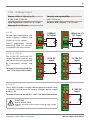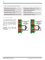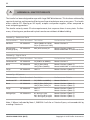
1
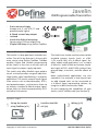
1 Javelin USB Programmable Transmitter › › › › › 2-wire universal input Accepts mA, V, mV, RTD, TC and potentiometer signals 4–20mA current loop output Isolated Hassle-free DIN-rail mounting Space-saving (12.5mm wide) case Simple USB setup Using Define ToolBox General Description The Javelin is a loop powered, isolated transmitter. One of its key features is its easy software setup using Define ToolBox. ToolBox enables simple and flexible programming of the Javelin in less than a minute, with no input signal or power supply required. The Javelin also offers flexible input options to suit a virtually endless range of industries. High quality signal conditioning is a popular application. The Javelin accepts input signals from sensors such as thermocouples, RTD's, and potentiometers, and converts them to an industry standard 4–20mA output signal, where they can then be processed by PLC's and other instruments. The Javelin can also be used to convert other standard process signals (such as ±10V, 1–5V, and 0–10V) to a 4–20mA signal. Another widely used application is as a simple 4–20mA in, and 4–20mA out isolator, to protect inputs of PLC's and SCADA systems from ground loops, transients, and the effects of EMC. More sophisticated applications are also catered to. For example, a level signal from an odd shaped tank can be converted to a 4–20mA signal representing volume, by using the in-built linearization table. To start exploring the capabilities of your Javelin, install ToolBox now (see Section 5). p6 Quick start Set up the Javelin using ToolBox (p12) Copyright © 2015 Define Instruments Install on the DIN rail (p8) Wiring (p15) JAV-2DLI-MAN-15V01 (0615) 2 CONTENTS Contents ............................................................. 2 7- Wiring ....................................................... 15 Safety Notices ..................................................... 3 7.1 - Terminal Access ............................... 15 1- Specifications .............................................. 3 7.2 - Screw Terminal Wiring .................... 15 1.1 - Ordering Codes ................................. 3 7.3 - Javelin Top & Bottom Views ............ 16 1.2 - General Specifications ....................... 4 7.4 - 4–20mA Output .............................. 16 Front View & Status LED ............................ 5 7.5 - Signal Input ..................................... 17 2.1 - Javelin Front View ............................. 5 7.5A - Thermocouple ....................... 17 3- Quick-Start .................................................. 6 7.5B - RTD ....................................... 18 4- Hardware Installation ................................ 7 7.5C - Current .................................. 18 4.1 - Case Diagram .................................... 7 7.5D - Voltage ................................. 19 4.2 - Installation Environment ................... 7 7.5E - Potentiometer ....................... 20 2- 4.3 - Installation Instructions .................... 8 8- Maintenance ............................................. 21 4.4 - EMC Installation Guidelines .............. 9 8.1 - Calibration ....................................... 21 5- Software Installation ............................... 10 8.2 - Troubleshooting .............................. 21 6- Software Configuration ........................... 12 Using ToolBox A - Appendix A - EMC Test Results ................ 22 6.1 - Bridge Key ....................................... 12 B- Appendix B - Warranty & ......................... 23 User's Responsibility 6.2 - Using ToolBox .................................. 13 6.3 - ToolBox Interface Overview ............ 14 JAV-2DLI-MAN-15V01 (0615) Copyright © 2015 Define Instruments 3 SAFETY NOTICES For your safety and the prevention of damage to the Javelin, as well as other equipment connected to it, please read and carefully observe all safety regulations and instructions. Consult this manual carefully in all cases where hazard symbols are marked on your Javelin unit. Define Instruments has not approved any change or modification to this device by users. Any modification or change could void users' authority to operate this equipment. Use of this instrument in a manner not specified by the manufacturer may compromise the protection provided by the instrument. This instrument should not be used to directly drive valves, motors, or other actuators, unless equipped with appropriate safeguards. The safety of any system incorporating this unit is the responsibility of the assembler of the system. It is the responsibility of the user to identify potential hazards that may arise in the event of a fault to unit, and implement safeguards for the prevention of harm to persons or equipment. Class 2 The power supply used for the Javelin must be UL rated in accordance with UL1310/ UL1585 or LPS in accordance with UL60950-1. Symbol definitions CAUTION CAUTION Risk of electric shock Please refer to user manual. Risk of danger Please refer to user manual. 1 SPECIFICATIONS 1.1 - Ordering codes JAV-2DLI USB Programmable Transmitter 2-wire isolated universal input, 4–20mA loop output BRIDGE-KEY Sold separately Copyright © 2015 Define Instruments USB Bridge Key for software programming Not UL approved JAV-2DLI-MAN-15V01 (0615) 4 1.2 - General specifications Input Construction Universal 2-wire isolated input See 7.5A–E for full specifications 35mm DIN rail mount casing IP20 rated. Installation Category II; Pollution Degree 2; Flame resistant Output Output 4–20mA or 20–4mA (loop powered) Dimensions (H x W x D) 90 x 12.5 x 112mm ( 3.54 x 0.49 x 4.41") Resolution 1μA Single unit weight 77g (2.7oz) Output load resistance 650Ω at 24V DC (50Ω/V above 10.5V DC) Status LED See 2.1A for status definitions Max output current Limited to <28mA Isolation test voltages between input/ output 2500V AC for 1min Accurate to <±0.03% FSO typical Ambient drift <±0.003%/°C FSO typical Response time 400msec typical (10–90% 300msec typical) Environmental conditions Operating temp -20 to 55°C (-4 to 131°F) Storage temp -20 to 65°C (-4 to 149°F) Operating humidity 5–85%RH max (non-condensing) Altitude 2000m (6561ft) Compliances Power IP20 enclosure rating Power supply 10.5–36V DC EMC compliance Emissions (EN 61326). Immunity (EN 61326). Safety (EN 61010-1). Supply voltage sensitivity < ±0.005%/V FSO UL Listed File Number E473114 USB programming Simple software programming Connect using the Bridge Key (sold separately). Program in less than a minute using Define ToolBox (see Section 6). JAV-2DLI-MAN-15V01 (0615) Copyright © 2015 Define Instruments 5 2 FRONT VIEW & STATUS LED 2.1 - Javelin front view A Status LED See 8.2 for Troubleshooting LED State Definition On for 2 sec Power supplied - starting up Flashing (½ sec on, ½ sec off) Operating normally Flashing (3 sec on, 1 sec off) Sensor break On continuously Fault Off Fault, or no 4–20mA current B Copyright © 2015 Define Instruments USB Programming Jack See 6.1 for connection instructions JAV-2DLI-MAN-15V01 (0615) 6 3 QUICK-START 1 - Configure your Javelin using ToolBox The Javelin's factory default input is RTD Pt100 (0–100°C) . If you wish to keep the default, or your distributor has already configured the Javelin for you, skip to Step 2 now. To change your input type or output scaling: A Install Define ToolBox (see Section 5). B Connect the Javelin to your computer using the USB Bridge Key (see 6.1). Then launch ToolBox and click the 'Connect' button (see 6.2). C Configure your system as required, referring to 6.2–6.3 in this manual, and also the Help Panel in the software. You may like to wire your transmitter now, using the diagrams in the Help Panel as a guide. D When you are finished, click 'Disconnect' in ToolBox, and then disconnect the Javelin from your PC. 2 - Hardware installation A Mount the Javelin on a DIN rail in an enclosure, referring to the instructions in Section 4. 3 - Wiring A Wire the Javelin, starting from the terminals at the back of the unit and working towards the front of the unit. Refer to Section 7 for wiring instructions. JAV-2DLI-MAN-15V01 (0615) Copyright © 2015 Define Instruments 7 4 HARDWARE INSTALLATION 4.1 - Case diagram 35mm DIN Rail 90 mm (3.54") 12.5mm 12.5mm (0.49") (0.49") 112mm (4.41") 4.2 - Installation environment The Javelin must be installed in a location that does not exceed the maximum operating temperature, and at a safe distance from other devices that generate excessive heat. The installation environment should provide good air circulation to the unit. Copyright © 2015 Define Instruments The plastic casing and product label may be cleaned, if required, using a soft, damp cloth and neutral soap product. Caution should be exercised when cleaning the unit to avoid water to dripping inside, as this will damage the internal circuits. JAV-2DLI-MAN-15V01 (0615) 8 4.3 - Installation instructions The Javelin is rated IP20, and is designed for installation on a 35mm DIN rail. The unit must be installed in an enclosure, to protect it from weather conditions and dust, and also to prevent any accidental contact with potentially hazardous voltages. A - DIN Rail Mounting (Fig 1) Fig 1 To clip the unit onto the DIN rail: (1) Hook the upper part of the unit onto the rail, and then (2) Press down towards the rail until the lower hook clicks into place. The Javelin may be mounted side-by-side with other Javelins on the DIN rail. Allow at least 5cm (1.97") clear space above and below the unit for airflow and wiring. B - Wiring Refer to Section 7 in this manual. Fig 2 C - Removal from DIN Rail (Fig 2) The unit may be unclipped from the DIN rail if required by pressing the straight tab under the rail. Squeeze the tab towards the back of the Javelin with your finger, while levering the whole unit up with your other hand. This will release the hook, allowing the unit to be detached from the DIN rail. JAV-2DLI-MAN-15V01 (0615) Copyright © 2015 Define Instruments 9 4.4 - EMC installation guidelines The Javelin has been designed to cope with large EMC disturbances. This has been achieved by continual testing and improvement of filtering and layout techniques over many years. B The Javelin meet CE noise requirements, and even surpass them in many tests. (For full details and test results, see Appendix A.) However in some applications with less than optimum installations and large power switching, the EMC performance of the Javelin can be further improved, by: A Installing the unit in an earthed metal enclosure. This is particularly useful if the control box is mounted close to large power switching devices like contactors. Every switching cycle there is a possibility of generating a large amount of near field radiated noise. The metal enclosure, acting as a faraday cage, will shunt this radiation to ground and away from the Javelin. Using shielded cable on sensitive input and control signal lines. Good results can be obtained by grounding the shields to the metal enclosure close to the entry point. All cables act as aerials and pick up unwanted R.F. radiated signals and noise; the earthed shield acts as a faraday cage around the cables, shunting the unwanted energy to ground. Shields can also help with capacitively coupled noise typically found in circumstances when signal cable is laid on top of noisy switching power cables. Of course in this case you are better off to keep separate signal and power lines. C Laying cable on earthed cable trays can also help reduce noise seen by the Javelin. This is particularly useful if there are long cable runs, or the unit is close to radiating sources such as two way radios. Further improvements can be made with this type of noise by increasing the physical distance from the power devices. For example, increasing the control box distance from 6” to 12” from the noise source will reduce the noise seen by the control box by a factor of 4. Probably the cheapest and best results in this situation could be obtained by adding RC snubbers to the contactors or power switches. Copyright © 2015 Define Instruments JAV-2DLI-MAN-15V01 (0615) 10 5 SOFTWARE INSTALLATION ToolBox offers a smart, no-fuss setup experience for your Javelin, and has been designed to simplify and speed up configuration. You must install ToolBox before connecting the Javelin to your computer. If you have already connected your Javelin using the Bridge Key, please disconnect before continuing. A Download the latest version of ToolBox from www.defineinstruments.com/toolbox For ease of access, we recommend saving the install file on your desktop. If you cannot locate the install file, check whether your browser has saved it in your Downloads folder. B Extract the install file from the zip folder. Right-click on the zip folder and choose 'Extract All', (or extract the file using another extraction utility of your choice). C Double-click on the extracted .msi install file. This will launch the ToolBox installer. Depending on your security settings, a 'Security Warning' dialogue may appear. If you see the security message, click 'Run'. JAV-2DLI-MAN-15V01 (0615) Copyright © 2015 Define Instruments 11 D The ToolBox setup wizard will launch. Click 'Next' to get started. E The wizard will also ask for confirmation that you wish to begin the installation. Click 'Next' to continue. F The wizard will prompt you to select an installation folder. You may accept the default installation folder, or select an alternative location by clicking 'Browse'. Click 'Next' to continue. G The install wizard will now install ToolBox. Please wait. This process usually takes 2-3 minutes, but may take longer in some situations. H When the installation has successfully completed, the following dialogue will appear. Click 'Close' to exit. The installer will place an icon on your desktop for easy access to ToolBox. The downloaded .zip and .msi installer files are no longer needed, and may be deleted if desired. Copyright © 2015 Define Instruments JAV-2DLI-MAN-15V01 (0615) 12 6 SOFTWARE CONFIGURATION USING TOOLBOX 6.1 - Bridge Key Install the ToolBox software (see Section 5) before connecting the Javelin to your PC. Connect the Javelin to your computer's USB port using the Bridge Key. No power supply is required during programming, as the Javelin is powered by the USB. The interface cable connects to the USB programming jack on the front of the Javelin (see 2.1B). A USB extension cable is supplied for your use if required - this is often used for convenience in accessing USB ports located at the back of the computer. CAUTION - Risk of damage Ensure that all connections between the Bridge Key and your Javelin are secure. Attempting to connect when cables are not firmly pushed in may result in connection faults, and could also cause damage to the unit or your PC. Always use the windows ‘Safely remove hardware’ function before unplugging the Bridge Key from your computer. CAUTION Not UL approved The Bridge Key is sold separately to the Javelin and has not been certified for UL. Javelin Bridge Key Interface Cable USB Extension Cable (If Necessary) Install Define ToolBox & connect all other cables first. PC JAV-2DLI-MAN-15V01 (0615) Copyright © 2015 Define Instruments 13 6.2 - Using ToolBox Define ToolBox enables full configuration of your Javelin. To set up the transmitter, only the Bridge Key is required. No power supply or input signal is needed. A Referring to the instructions in Section 5, download and install the latest version of ToolBox from: www.defineinstruments.com/toolbox B Connect the Javelin to your computer using the Bridge Key as shown in 6.1. C Double-click the ToolBox icon on your desktop to launch the ToolBox program. D Click the green 'Connect' button. This will scan your computer's Com ports and automatically connect to your device. Input/Output Dynamic help panel The Input/Output tab is the main area for configuring your Javelin. Select your precalibrated input type, and adjust the input range and units. The dynamic help panel auto-updates with relevant explanations, diagrams and tips as you configure your Javelin. If the unit is wired and powered up, you can also view a live graph of the analogue output - great for commissioning! Advanced Advanced features enable you to save a configuration, or load a previously saved configuration. This provides a simple way to duplicate a configuration, for cloning or troubleshooting. It is also possible to export a PDF configuration certificate, with custom fields for support contact information. Copyright © 2015 Define Instruments Connection problems? ToolBox will auto-detect and connect to your Javelin when you click the 'Connect' button. If you encounter connection problems: › › › Ensure that all connections between the device and your computer are secure. Try disconnecting and reconnecting the USB, or using a different USB port on your PC. Disconnect any additional compatible devices. The software's auto-detect feature will not work if multiple compatible devices are connected to your computer at the same time. JAV-2DLI-MAN-15V01 (0615) 14 6.3 - ToolBox interface overview Main Navigation Tabs Input/Output and Advanced configuration pages. Control Area Main control area for configuring your system. Any changes made in this area will bring up the Apply Bar (see below) Connection Panel Disconnect button Connection status Apply Bar Help Panel Appears if you have made any changes in the Control Area. ToolBox will not allow you to browse to a new tab in the Main Navigation with unapplied changes to your configuration. Diagrams, explanations, and helpful tips will automatically appear in this panel as you configure your Javelin. JAV-2DLI-MAN-15V01 (0615) Copyright © 2015 Define Instruments 15 7 WIRING 7.1 - Terminal access Fig 3 Electrical connections are made via angled screw terminals on the top and bottom of the Javelin. Wire for Terminal L blocks access to Terminal H Due to the angle of the terminals, inserting a wire in a front terminal will block screwdriver access to the terminal directly behind it. For example, in Fig 3 (right), the wire for Terminal L on the underside of the Javelin blocks access to Terminal H. Because of this, the unit must be wired in sequence, starting with the terminals at the back of the unit and moving towards the front. 7.2 - Screw terminal wiring Wiring diagrams for your Javelin can be found on the product label, in this manual (7.3–7.5), or in the Help Panel of the Define ToolBox software. When wiring your Javelin, check all connections against the terminal letters, which are embossed on the unit next to the screw for each terminal. All conductors must conform to the unit's voltage and current ratings, and be suitably rated for the expected temperature range to be incurred. Follow all local codes and regulations when wiring and installing your Javelin. Each terminal is rated to accept one wire from #14 AWG (2.5mm) to #20 AWG. However it is also possible to accept two #18 AWG wires, or up to four #20 AWG wires. CAUTION All field wiring must be rated at a minimum of 80°C (176°F). Strip the wire, leaving around 0.25" (6mm) of bare lead exposed. If you are using stranded wire, this should be tinned with solder. Insert the lead into the terminal in the correct position, and tighten until the wire is secure. Verify tightness by pulling on the wire. Copyright © 2015 Define Instruments JAV-2DLI-MAN-15V01 (0615) 16 7.3 - Javelin top & bottom views A 4–20mA Output (Terminals O–P, See 7.4) B Signal Input (Terminals G–H & –L, See 7.5) Wire terminals G–H first, where applicable. See 7.1 for more on terminal access. Top of Unit Bottom of Unit DIN Rail DIN Rail Terminals Q–R, M–N and E–F are not used. 7.4 - 4–20mA Output See 7.3A, Terminals O–P 10.5~36V DC Wire your 4–20mA loop output and 10.5–36V DC power supply as shown (right). Terminals O–P are located on the top side of the Javelin unit. Class 2: The power supply used for the Javelin must be UL rated in accordance with UL1310/ UL1585 or LPS in accordance with UL60950-1. JAV-2DLI-MAN-15V01 (0615) Rload Copyright © 2015 Define Instruments 17 7.5 - Signal input See 7.3B, Terminals G–H & –L Wire the universal input for your signal type, as detailed on the following pages. Input specifications and wiring for all available Javelin input types can be found below (7.5A–E). All terminals for the signal input are located on the bottom side of the Javelin unit. CAUTION Risk of electric shock. Dangerous and lethal voltages may be present on the terminals of the unit. Please take appropriate precautions to ensure safety. CAUTION Risk of danger. The sensor input can potentially float to dangerous and unexpected voltages depending on what external circuit it is connected to. Appropriate considerations must be given to the potential of the sensor input with respect to earth common. 7.5A - Thermocouple input Thermocouple types B, E, J, K, N, R, S, T CJC drift <0.02°C/C typical for all inputs Input impedance >500KΩ min Sensor open Upscale/Downscale (software programmable) TC lead resistance 100Ω max Cold junction comp. -10 to 60°C (14 to 140°F) Accuracy 0.1% of FSO±1°C typical Temperature (thermocouple) The thermocouple (TC) is one of the most common temperature sensors used in industry. It relies on the Seebeck coefficient between dissimilar metals. TC Input TC type is selected with reference to the application temperature range and environment. The most common TC types for general purpose applications are J and K. Supported thermocouple types/ranges Supported thermocouple types/ranges K -200°C (-328°F) 1260°C (2300°F) R 0°C (32°F) 1700°C (3092°F) B 400°C (752°F) 1800°C (3272°F) S 0°C (32°F) 1700°C (3092°F) E -200°C (-328°F) 700°C (1292°F) T -200°C (-328°F) 400°C (752°F) J -200°C (-328°F) 1000°C (1832°F) N -200°C (-328°F) 1300°C (2372°F) Copyright © 2015 Define Instruments JAV-2DLI-MAN-15V01 (0615) 18 7.5B - RTD input RTD types Pt100 (3-wire RTD DIN 43760:1980) or Pt1000 (3-wire RTD standard) Calibrated range -200 to 850°C (-328 to 1562°F), 0.1°C res Lead resistance 10Ω/lead max recommended Sensor current 0.15mA continuous Sensor open Upscale/Downscale (software programmable) Accuracy 0–300°C= ±0.15°C <0°C or >300°C= ±0.3°C Ambient drift 0.003°C/C typical Temperature (RTD) The RTD (standing for Resistance Temperature Device) is highly stable and accurate, and is fast becoming the most popular temperature sensor in industry. Often referred to as Pt100 and Pt1000, the Pt represents platinum (the dominant metal in its construction), and 100/1000 is the resistance in ohms at 0°C. RTD Input Note that terminals G–H must be wired first - see 7.1 for more information. Supported RTD types/ranges Pt100 -200°C (-328°F) 850°C (1562°F) Pt1000 -200°C (-328°F) 850°C (1562°F) 7.5C - Current input Range 0/4–20mA Accuracy 0.1% FSO max Input resistance 10Ω Ambient drift <50ppm/°C of FS input Linearity & repeatability 0.1% FSO max Response 400msec 0/4–20mA DC 0/4–20mA DC is the most commonly used analogue signal in industry, and is universally accepted. 0/4−20mA DC Input As a current loop, it is unaffected by voltage drops in cables, and can be transmitted over long distances without signal degradation. JAV-2DLI-MAN-15V01 (0615) Copyright © 2015 Define Instruments 19 7.5D - Voltage input Ranges ±200mV, –100mV to 1V, 0–10V, ±10V, 0–50V DC Linearity and repeatability 0.05% FSO max Input impedance >500KΩ on all ranges Ambient drift <50ppm/°C of FS input Accuracy 0.1% FSO max mV DC For low signal applications, the Javelin supports ±200mV and -100mV to 1V DC ranges. ±200mV DC Input -100mV to 1V DC Input ±10V DC Input 0−10V DC Input Typical applications include measuring large DC currents using external current shunts. 0–10V & ±10V DC The 0–10V DC and ±10V DC ranges are both common process signals that are generated by transmitters, meters and PLCs. Terminal H must be wired first - see 7.1 for more information. 0–50V DC The 0–50V DC range is a higher voltage general purpose range is typically used to measure battery voltages, power supply outputs, etc. 0−50V DC Input Terminal H must be wired first - see 7.1 for more information. CAUTION Risk of electric shock Exercise extreme caution when handling high voltage inputs. Copyright © 2015 Define Instruments JAV-2DLI-MAN-15V01 (0615) 20 7.5E - Potentiometer input Potentiometer input 3-wire Field programmable span 0.1–100% Potentiometer resistance Low range (<2KΩ) or High range (<1MΩ) Linearity and repeatability <±0.05% FSO typical Excitation voltage Variable Response time 400msec Field programmable zero 0–90% of span Temperature drift <50ppm/°C 3 wire potentiometer A 3 wire potentiometer is typically used to measure position. The low or high potentiometer range can be programmed to your unit using the ToolBox software. Potentiometer Input Low range (<2kΩ) Potentiometer Input High range (<1MΩ) Terminals G–H must be wired first - see 7.1 for more information. JAV-2DLI-MAN-15V01 (0615) Copyright © 2015 Define Instruments 21 8 MAINTENANCE 8.1 - Calibration Your Javelin has been fully calibrated at the factory, and can be recalibrated in software using Define ToolBox (see 6.2 to connect). Scaling to convert the input signal to a desired output value is also done using ToolBox. If your Javelin unit appears to be behaving incorrectly or inaccurately, refer to troubleshooting (8.2) before attempting to calibrate it. When recalibration is required (generally every 2 years), it should only be performed by qualified technicians using appropriate equipment. Calibration does not change any user programmed parameters. However, it may affect the accuracy of the input signal values previously stored. 8.2 - Troubleshooting Status LED Definition/Resolution On for 2 seconds Power supplied to Javelin - starting up. Flashing (½ sec on, ½ sec off) Javelin is operating normally. Flashing (3 sec on, 1 sec off) Sensor break. Check sensor and sensor connections. Replace sensor if necessary. On continuously Fault. Return unit for repair. Off Fault, or no 4–20mA current. Check power supply and connections. If OK, return unit for repair. For further assistance, please contact technical support using the contact details listed at the end of this document. Copyright © 2015 Define Instruments JAV-2DLI-MAN-15V01 (0615) 22 A APPENDIX A - EMC TEST RESULTS The Javelin has been designed to cope with large EMC disturbances. This has been achieved by constantly testing and improving filtering and layout techniques over many years. The Javelin offers superior R.F. filtering on all inputs, outputs and power supplies, when compared to most competing products. The Javelin not only meets CE noise requirements, but surpasses them in many tests. Furthermore, all testing was performed in plastic enclosures without shielded cabling. Immunity - Enclosure Ports Phenomenon Basic Standard Test Value Performance Criteria EM Field IEC 61000-4-3 10Vm (80Mhz to 1GHz) Meets Criterion A 3V/m (1.4GHz to 2.7Ghz) Electrostatic Discharge (ESD) IEC 61000-4-2 4KV/8KV contact/air Meets Criterion A (Note 1) Meets NAMUR NE 21 recommendation Immunity - Signal Ports Phenomenon Basic Standard Test Value Performance Criteria Conducted RF IEC 61000-4-6 3V(150Khz to 80Mhz) Meets Criterion A Burst IEC 61000-4-4 1KV (5/50ns,5Khz) 1KV(5/50ns,100Khz) Meets Criterion A (Note 1) Meets NAMUR NE 21 recommendation Surge IEC 61000-4-5 1KV L-E Meets Criterion A (Note 1) Immunity - AC power Phenomenon Basic Standard Test Value Performance Criteria Conducted RF IEC 61000-4-6 3V (150Khz to 80Mhz) Meets Criterion A Burst IEC 61000-4-4 2KV (5/50ns, 5Khz) L-N 1KV (5/50ns, 5Khz) L-L Meets Criterion A (Note 1) Meets Criterion A (Note 1) Surge IEC 61000-4-5 2KV L-E 1KV L-L Meets Criterion A (Note 1) Meets Criterion A (Note 1) Voltage Dips IEC 61000-4-11 0% during 1 cycle 40% during 10/12 cycles 70% during 25/30 cycles Meets Criterion A (Note 1) Meets Criterion A (Note 1) Meets Criterion A (Note 1) Note 1: Where indicated by Note 1, EN61326-1 calls for a Criterion B pass; unit exceeds this by meeting Criterion A. JAV-2DLI-MAN-15V01 (0615) Copyright © 2015 Define Instruments 23 EMC Test: Performance Criteria Performance Criterion A During testing, normal performance within the specification limits. B Performance Criterion B During testing, temporary degradation, or loss of performance or function which is self-recovering. APPENDIX B - WARRANTY & USER'S RESPONSIBILITY Warranty Define Instruments warrants that its products are free from defects in material and workmanship under normal use and service for a period of one year from date of shipment. Define Instruments’s obligations under this warranty are limited to replacement or repair, at its option, at its factory, of any of the products which shall, within the applicable period after shipment, be returned to Define Instruments’s facility, transportation charges pre-paid, and which are, after examination, disclosed to the satisfaction of Define Instruments to be thus defective. The warranty shall not apply to any equipment which shall have been repaired or altered, except by Define Instruments, or which shall have been subjected to misuse, negligence or accident. In no case shall Define Instruments’s liability exceed the original purchase price. The aforementioned provisions do not extend the original warranty period of any product which has been either repaired or replaced by Define Instruments. User’s Responsibility We are pleased to offer suggestions on the use of our various products, by way of printed matter, on our website, or through direct contact with our sales/application engineering staff. However, since we have no control over the use of our products once they are shipped, NO WARRANTY, WHETHER OF MERCHANTABILITY, FITNESS FOR PURPOSE OR OTHERWISE is made beyond repair, replacement, or refund of purchase price at the sole discretion of Define Instruments. Users shall determine the suitability of the product for the intended application before Copyright © 2015 Define Instruments using, and the users assume all risk and liability whatsoever in connection therewith, regardless of any of our suggestions or statements as to application or construction. In no event shall Define Instruments’s liability, in law or otherwise, be in excess of the purchase price of the product. Define Instruments cannot assume responsibility for any circuitry described. No circuit patent or software licenses are implied. Define Instruments reserves the right to change circuitry, operating software, specifications, and prices without notice at any time. JAV-2DLI-MAN-15V01 (0615) Define Instruments New Zealand (Head Office) United States (Dallas, TX) 10B Vega Place, Rosedale, Auckland 0632, New Zealand Ph: 214.926.4950 PO Box 245 Westpark Village, Auckland 0661, New Zealand www.defineinstruments.com Ph: +64 (9) 835-1550 | Aus: 1800 810-820 Fax: +64 (9) 835-1250 [email protected] www.defineinstruments.co.nz [email protected] South Africa (Johannesburg) Ph: 087 945 2700 [email protected] www.defineinstruments.co.za Javelin Revision Code: JAV-2DLI-MAN-15V01 Date Code: 150615