1
Ground Bond Tester
19572
User’s Manual
Version 1.3
March 2007
P/N A11 000966
Legal Notices
The information in this document is subject to change without notice.
Chroma ATE INC. makes no warranty of any kind with regard to this manual, including, but
not limited to, the implied warranties of merchantability and fitness for a particular purpose.
Chroma ATE INC. shall not be held liable for errors contained herein or direct, indirect,
special, incidental or consequential damages in connection with the furnishing, performance,
or use of this material.
CHROMA ATE INC.
66 Hwa-Ya 1st Rd., Hwa-Ya Technical Park, Kuei-Shan Hsiang, Taoyuan Hsien, Taiwan
Copyright Notices. Copyright 2004-2007 Chroma ATE INC., all rights reserved.
Reproduction, adaptation, or translation of this document without prior written permission is
prohibited, except as allowed under the copyright laws.
ii
Warranty
All Chroma instruments are warranted against defects in material and workmanship for a
period of one year after date of shipment. Chroma agrees to repair or replace any assembly
or component found to be defective, under normal use during this period. Chroma's
obligation under this warranty is limited solely to repairing any such instrument, which in
Chroma's sole opinion proves to be defective within the scope of the warranty when returned
to the factory or to an authorized service center. Transportation to the factory or service
center is to be prepaid by purchaser. Shipment should not be made without prior authorization
by Chroma.
This warranty does not apply to any products repaired or altered by persons not authorized by
Chroma, or not in accordance with instructions furnished by Chroma. If the instrument is
defective as a result of misuse, improper repair, or abnormal conditions or operations, repairs
will be billed at cost.
Chroma assumes no responsibility for its product being used in a hazardous or dangerous
manner either alone or in conjunction with other equipment. High voltage used in some
instruments may be dangerous if misused. Special disclaimers apply to these instruments.
Chroma assumes no liability for secondary charges or consequential damages and in any
event, Chroma's liability for breach of warranty under any contract or otherwise, shall not
exceed the purchase price of the specific instrument shipped and against which a claim is
made.
Any recommendations made by Chroma for use of its products are based upon tests believed
to be reliable, but Chroma makes no warranty of the results to be obtained. This warranty is
in lieu of all other warranties, expressed or implied, and no representative or person is
authorized to represent or assume for Chroma any liability in connection with the sale of our
products other than set forth herein.
CHROMA ATE INC.
No.66 Hwa-Ya 1st Rd, Hwa-Ya Technical Park,
Kuei-Shan Hsiang, Taoyuan Hsien, Taiwan
Tel: 886-3-327-9999
Fax: 886-3-327-2886
http://www.chromaate.com
iii
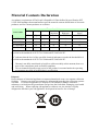
Material Contents Declaration
A regulatory requirement of The People’s Republic of China defined by specification SJ/T
11364-2006 mandates that manufacturers provide material contents declaration of electronic
products, and for Chroma products are as below:
Hazardous Substances
Part Name
Lead
Mercury Cadmium
Hexavalent
Chromium
Polybrominated Polybromodiphenyl
Biphenyls
Ethers
Hg
Cd
Cr6+
PBB
PBDE
PCBA
Pb
°
O
O
O
O
O
CHASSIS
°
O
O
O
O
O
ACCESSORY
°
O
O
O
O
O
PACKAGE
O
O
O
O
O
O
“O” indicates that the level of the specified chemical substance is less than the threshold level
specified in the standards of SJ/T-11363-2006 and EU 2005/618/EC.
“°” indicates that the level of the specified chemical substance exceeds the threshold level
specified in the standards of SJ/T-11363-2006 and EU 2005/618/EC.
1.
2.
Chroma is not fully transitioned to lead-free solder assembly at this moment; however,
most of the components used are RoHS compliant.
The environment-friendly usage period of the product is assumed under the operating
environment specified in each product’s specification.
Disposal
Do not dispose of electrical appliances as unsorted municipal waste, use separate collection
facilities. Contact your local government for information regarding the collection systems
available. If electrical appliances are disposed of in landfills or dumps, hazardous
substances can leak into the groundwater and get into the food chain, damaging your health
and well-being. When replacing old appliances with new one, the retailer is legally
obligated to take back your old appliances for disposal at least for free of charge.
iv
ÚÚÚ
Inspection and Examination ÚÚÚ
Before the instrument exit the factory, we have a series of inspection and measurement on
mechanical and electrical characteristics. Make sure its function of operating for the quality
warranty of the product. If collision results in damages and defects of the quality and the
performance, please contact us for promptly service.
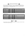
Standard Accessory
Item
Part No.
Q’ty
Remark
Power cord
W12 010130
1
Line Cord IEC+USA (BLK) AB19
3P – 2P adapter
N31 000039
1
Power cord adapter
Test cable
W38 027900
1
Grounding test cable 19572GB/TN031231
Fuse 10A slow blow
A21 016900
2
10A SLOW 110VAC used
Fuse 5A slow blow
A21 000600
2
5A SLOW 240VAC used
Note: When order the accessories, just name item and part no..
Optional Accessory
Item
Part No.
Q’ty
RS232 link cable
W32 844000
1
GP-IB Interface
GP-IB link cable 1M
GP-IB link cable 2M
Print Board
9 19050899
Y91 013555
Y91 013556
9 19051099
1
1
1
1
ÚÚÚ
Note
Remark
25Pin male to 25Pin female and 9Pin
female 2M
19050 GP-IB interface
For connecting computer control
For connecting computer control
19050 series
ÚÚÚ
The detailed about using the notice items and the danger of operating are described in Chapter
3 “Notices before using” of this manual.
v
ÚÚÚ Storage. Freight. Maintenance ÚÚÚ
Storage
When don’t use the device, please pack it properly and store under a good environment. (The
packing is no needed when the device under appropriate environment.)
Freight
Please use the original packing material when move the device. If the packing material is
missing, please use the equivalent buffer material to pack and mark it fragile and waterproof
etc to avoid the device damage during movement. The device belongs to precise equipment,
please uses qualified transportation as possible. And avoid heavy hitting etc to damage the
device.
Maintenance
There is no maintenance operation for the general users. (Except for the note in the manual.)
Please contact our company or agent when the device occurred the user judgment abnormal.
Don’t maintain by yourself to avoid occurred unnecessary danger and serious damage to the
device.
vi
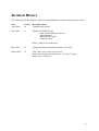
Revision History
The following lists the additions, deletions and modifications in this manual at each revision.
Date
April 2004
Version
1.0
Revised Sections
Complete this manual
June 2004
1.1
Modify “SYSTEM Setup”
“How to Enter Memory Process”
“Store Memory”
“PROGRAM Setting”
“Test Procedures”
Delete “How to Select Memory”
May 2005
1.2
Change the address and phone number of Chroma
March 2007
1.3
Add “Material Contents Declaration”
Delete the description of Disposal in “Storage. Freight.
Maintenance. Disposal”
vii
Ground Bond Tester 19572 User’s Manual
Table of Contents
1. Introduction .......................................................................................................................1-1
1.1
An Overview of Product .................................................................................1-1
1.2
Features ...........................................................................................................1-1
2. Specifications (18°C ∼ 28°C RH ≤ 70%) .........................................................................2-1
3. Notices before Using..........................................................................................................3-1
4. Panel Description...............................................................................................................4-1
4.1
Front Panel ......................................................................................................4-1
4.2
Rear Panel .......................................................................................................4-3
4.3
Notices and Procedures before Operation.......................................................4-4
4.4
SYSTEM Setup ...............................................................................................4-5
4.4.1
4.4.2
How to Enter SYSTEM Menu ................................................................................... 4-5
Operation Method ...................................................................................................... 4-5
4.5.1
4.5.2
4.5.3
4.5.4
How to Enter Memory Process .................................................................................. 4-6
Delete Memory........................................................................................................... 4-6
Recall Memory........................................................................................................... 4-7
Store Memory............................................................................................................. 4-7
4.6.1
4.6.2
How to Enter PRESET Setting Menu ........................................................................ 4-7
Operation Method ...................................................................................................... 4-8
4.5
Memory Management .....................................................................................4-6
4.6
PRESET Testing..............................................................................................4-7
4.7
PROGRAM Setting.........................................................................................4-9
4.7.1
4.7.2
4.7.3
4.8
Test Procedure Setting................................................................................................ 4-9
Operation Method ...................................................................................................... 4-9
Each Parameter Setting Data Description ................................................................ 4-10
How to Process Test ......................................................................................4-10
4.8.1
4.8.2
4.8.3
Offset Value Calibration of Test Cable..................................................................... 4-10
Connecting DUT Methods ....................................................................................... 4-10
Test Procedures ........................................................................................................ 4-11
4.9.1
4.9.2
KEY LOCK Setting.................................................................................................. 4-12
Canceling KEY LOCK............................................................................................. 4-12
4.9
KEY LOCK Function....................................................................................4-12
4.10
4.11
4.12
User Password Setting...................................................................................4-13
Remote Control .............................................................................................4-13
Output Signal.................................................................................................4-15
5. Remote Interface Description ..........................................................................................5-1
5.1
RS232 Interface Specification.........................................................................5-1
5.1.1
5.1.2
5.1.3
5.1.4
5.2
Remote Interface Command............................................................................5-2
5.2.1
5.2.2
5.2.3
5.3
5.4
Data Format................................................................................................................ 5-1
Command Format....................................................................................................... 5-1
Connector ................................................................................................................... 5-1
Connection Method .................................................................................................... 5-2
Command Summary................................................................................................... 5-2
Command Description................................................................................................ 5-5
SCPI Status System.................................................................................................. 5-12
Error Messages..............................................................................................5-13
RS232 Operation Using Basic.......................................................................5-14
ix
Ground Bond Tester 19572 User’s Manual
6. GPIB Description (Option)...............................................................................................6-1
6.1
Guide ...............................................................................................................6-1
6.2
Interface Specification.....................................................................................6-1
6.2.1
6.2.2
6.2.3
6.3
GPIB Related Panel Description .....................................................................6-2
6.3.1
6.3.2
6.4
6.5
Applicable Standard ................................................................................................... 6-1
Interface Capability .................................................................................................... 6-1
Using Code................................................................................................................. 6-1
Address Setting .......................................................................................................... 6-2
Remote / Local ........................................................................................................... 6-3
Interface Message............................................................................................6-3
GPIB Control / Setting Command Descriptions .............................................6-3
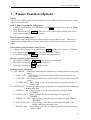
7. Printer Function (Option) ................................................................................................7-1
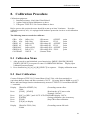
8. Calibration Procedure ......................................................................................................8-1
8.1
Calibration Menu.............................................................................................8-1
8.2
Start Calibration ..............................................................................................8-1
8.3
Complete Calibration ......................................................................................8-3
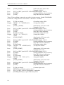
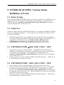
9. INTERLOCK OPEN, Various Status Definition of Tester...........................................9-1
9.1
Before Testing .................................................................................................9-1
9.2
Under Test .......................................................................................................9-1
9.3
STEP HOLD TIME ≠ KEY, FAIL CONT. = OFF ..........................................9-1
9.4
STEP HOLD TIME = KEY, FAIL CONT. = OFF ..........................................9-1
9.5
STEP HOLD TIME ≠ KEY, FAIL CONT. = ON ............................................9-2
9.6
STEP HOLD TIME = KEY, FAIL CONT. = ON............................................9-2
10. GBSS MODE .................................................................................................................10-1
11. Maintenance...................................................................................................................11-1
11.1
General .......................................................................................................... 11-1
11.2
Cleaning ........................................................................................................ 11-1
11.3
Battery Replacement ..................................................................................... 11-1
11.4
Instrument Return.......................................................................................... 11-1
x
Introduction
1. Introduction
1.1 An Overview of Product
This automatic ground bond tester is designed to test ground resistance automatically for
electrical machinery and electronic devices.
For ground resistance, its test range is from 0~140mΩ, under 10A can up to 510 mΩ.
The output test current range is 3∼45A can be set arbitrarily.
1.2 Features
1. Clear Display
This instrument has the clearest design for setting the parameters of current states, time,
readings, memory no., procedures and states. All of them can be read from the display
directly.
2. Memory Backup
This instrument will backup the data after setting parameters save to the memory. The
data remain in the memory even though open the data after power-off. Therefore, if
the data is not necessary to backup, please don’t save to the memory avoid occupying
memory space.
3. High/Low Limit Comparison for Pass/Fail Judgment
The function of high/low limit comparison for Pass/Fail judgment is designed for
preventing the misjudgment due to bad connection or test cable tripped. This function
is able to detect if there is any bad connection or broken line.
4. Software Calibration
Use software to calibrate. It is no need to open cover, key in correct value by using
keyboard on panel completely. The calibration value saves in EEPROM. The
calibration result is correct, stable.
5. Remote Control
This instrument can extend [START] and [STOP] signals to control externally.
6. The Output of Test Result Signal
The test result can output by relay point on method, such as PASS, FAIL and TEST
signals output.
7. Keypad Locked Function
All of keypads are locked except for [STOP] in test state.
8. OFFSET Calibration Function
This instrument is with Offset Get function. This function can read OFFSET of test
terminal, line impedance of ground test under test status and then save in the memory.
Automatic deduction each test makes the test value more correct.
1-1
Specifications
2. Specifications (18°C ∼ 28°C RH ≤ 70%)
Ground Bond Tester
Output Current
Accuracy
Resistance Range
3.00 ~ 45.0A AC (Note1, 2).
3.00A ~ 30.00A 0.01A
30.1A ~ 45.0A
0.1A
± (1.5% of setting + 0.5% of full scale)
50Hz, 60Hz
± 0.1%
0.01 ∼ 45.0A
3.00A ~30.00A 0.01A
30.1A ~ 45.0A
0.1A
± (1.5% of reading + 0.5% of full scale)
0.1 ~ 510.0mΩ (Note2)
Resolution
(R display counts/ I display counts) ≥ 0.2, Resolution: 1mΩ
(R display counts/ I display counts) < 0.2, Resolution: 0.1mΩ
Accuracy (Note3)
± (2% of reading + 0.5% of full scale), Detail Spec. Range
Resolution
Accuracy
Output Frequency
Accuracy
Current Meter
Resolution
Resistance
510mΩ
e
g
n
a
R
s
n
o
i
t
a
c
i
f
i
c
e
p
S
150mΩ
100mΩ
10mΩ
3A
8A
Limit Value Setting
Offset Function
Offset Range
Test Time
Resolution
Memory Storage
Memories, Steps
30A
45A
Current
HI – LIMIT: 0.1 ~ 510.0mΩ
LOW–LIMIT: OFF, 0.1mΩ ~ HI – LIMIT Value,
510.0mΩ MAX.
0 ~ 100.0mΩ
0.5 ~ 999.0 sec. Continue (Note2)
0.1sec
10 steps or 99 groups for total 500 memory locations
2-1
Ground Bond Tester 19572 User’s Manual
Ambient Temperature and Relative Humidity
Specifications Range
18 to 28°C (64 to 82°F), ≤ 70% RH.
Operable Range
0 to 40°C (32 to 104°F), ≤ 80% RH.
Storage Range
-10 to 60°C (-14 to 140°F), ≤ 90% RH.
Power Requirement
Line Voltage
AC 100V, 120V, 220V ± 10%, 240V -10% ~ +5%
Frequency
50 or 60 Hz
Power Consumption
No load: < 100VA, With rated load: 880W MAX.
Dimension
320W x 105H x 400D mm
Weight
< 16 kg.
Safety
Ground Bond
Less than 100mΩ at 25Amp, 2sec
Hipot
Less than 5mA at 1.8kVac, 3sec
Insulation Resistance
Over 20MΩ at 500V 3sec
Line Leakage Current
Less than 3.5mA at 127V, 2sec, normal, reverse
Note1: For full rating output, the line input range is +10%, -5%.
Note2: 40 amp for TUV 120 seconds, 40.1 – 45amp continue is 60 seconds.
The maximum test resistance range is with offset value 510mΩ, at 8amp output.
Note3: For getting the optimal accuracy, please use the 4-wire type for measuring.
It is no need to do offset again. When offset value is lower than 10mΩ, it is over
test specification. By using offset can increase 5mΩ maximum specifications error.
2-2
Notices before Using
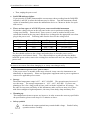
3. Notices before Using
Please read through the notices described in this chapter and memorize them to prevent any
accidents from happening.
■
Induction and electric shock
To avoid electric shock, please check the power of the tester related settings and
descriptions firstly before operating the tester.
■
Grounding
There is a safety grounding terminal at the instrument rear panel. Please use appropriate
test leads and tools to connect the grounding terminal surely. If it is not grounding
correctly, the chassis of test machine may contain high voltage when the power circuit or
the connecting line of any devices short-circuited with the grounding terminal. This is
very dangerous as it may cause electric shock if anyone touches the instrument under the
circumstances. Therefore, it is necessary to connect the safety grounding terminal to
earth correctly.
■
Remote control system
This system is capable of remote control. Usually it uses control signal of rear panel
coordinating with HI-POT series model (such as 1905X, 1907X) to do the high voltage
output control. For your safety and to prevent accidents, the following principles of
control must be performed accurately.
˙ Do not allow any unexpected high voltage output to cause any hazards.
˙ When the system has high voltage output, operators and other personnel are not
allowed to touch the DUT, test cable and probe and output terminal, etc.
■
Turn the power switch on or off Ú Caution Ú
Once the power switch is cut off, wait a few seconds to turn it on again. Do not turn
on/off the power switch repeatedly to avoid causing any errors.
■
Miscellaneous notices
Do not short circuit the instrument output line, grounding line, transmission line, or other
connector grounding line, and AC source to avoid the entire test device being charged to a
very dangerous voltage. If the tester is under full load output for a long period, the
bottom partial site of the tester may be high temperature over 50°C. Before moving the
tester, please power the tester off firstly as well as confirm the bottom site of the tester
decrease to below 30°C for avoiding the danger of burning.
■
Installation notices
When installs or operates the tester, the ventilation holes should be at least 10cm from
wall to keep adequate ventilation.
<<< Emergency Events >>>
■
Emergency management
In the emergency situations of electric shock, DUT on fire or system on fire, follow the
steps below to avoid causing bigger hazards.
˙ First, cut off the power switch.
3-1
Ground Bond Tester 19572 User’s Manual
˙ Then, unplug the power cord.
■
DANGER indicator failure
If you press the [START] button and the current meter shows readings but the DANGER
indicator is still off, it means the indicator may be failure. Turn the instrument off and
replace it immediately, then return the malfunction device to Chroma or dealer for repair
and services.
■
There are four types of AC INPUT power source used in this instrument
Switch the voltage selector on the rear panel to the correct position according to the
voltage used locally. Ensure the AC power source is same as marked on the power
switch that located on the rear panel, and the fuse is changed to the appropriate one when
plug in the power cord. Following table lists the fuses for the voltage used:
Mark
100
120
220
240
Center Voltage
100V
120V
220V
240V
Range
90V ∼ 110V
110V ∼ 130V
200V ∼ 240V
220V ∼ 250V
Fuse
10A Slow/250V
10A Slow/250V
5A Slow/250V
5A Slow/250V
The fuse should conform to the voltage used and replace it when the power cord is
unplugged to avoid electric shock. Use a flat screwdriver to pull open the fuse holder
inside the power socket, remove the existing fuse and insert the new one, then plug in the
power cord.
a Caution
Be sure to use correct fuse when changing it, or it may cause danger easily.
■
This instrument operates in AC power source
If the power source is unstable in the range selected, it may cause the instrument to act
abnormally or inaccurately. Please use appropriate equipment such as power regulator to
convert it to applicable power source.
■
Storage
The normal temperature range is 0°C ~ 40°C, 80% RH. The operation may incorrect if
over the range. The storage temperature is–10ºC ~ 60°C, 90% RH. If you are not
planning to use it for a long period of time, pack it with the original box for storage. For
the sake of correct test and safety of this instrument, make sure not to store it in a place
with direct sunlight or high temperature, also away from shaky, damp and dusty area.
■
Warming up
This instrument activates at power on; however, in order to meet the accuracy specified in
the specification, please warm it up for 15 minutes or above.
■
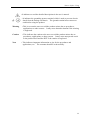
Safety symbols
: It indicates the output terminal may contain lethal voltage. Read all safety
operation notices carefully.
3-2
Notices before Using
: It indicates to read the detailed descriptions in the user’s manual.
: It indicates the grounding protect terminal, which is used to prevent electric
shock from the leakage on chassis. The ground terminal must connect to
earth before using the product.
Warning
: This is to warn the user to avoid the product misuse due to procedures,
applications or other reasons. It may cause hazard to human if the warning
is neglected.
Caution
: This indicates the caution to the user to avoid the product misuse due to
procedures, applications or other reasons. It may cause unexpected result
to the product itself and the DUT if the caution is neglected.
Note
: This indicates important information or tips for the procedures and
applications, etc. The contents should be read carefully.
3-3
Panel Description
4. Panel Description
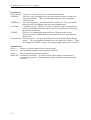
4.1 Front Panel
Front panel includes several function areas easy to use. This chapter will introduce each
control and information on screen to you.
STOP
MODEL
19572
CAL
PASS
FAIL
F1
A
PD
DANGER
TE
U
GROUND BOND TESTER
F2
START
F3
F4
DRIVE
DRIVE
SENSE
SENSE
SENSE
SENSE
RTN / LOW
RTN
LOW
Display Area
Function Key: There are different function descriptions under different screens. The
corresponding function key (F1-F4) on the right side of display. If the description part is
blank, it means the corresponding function key is invalid.
Status List: It indicate setting method, setting value range, test result fail status.
RMT
OFST
: If RMT is highlighted, it means the main machine under Remote state. The main
machine is controlled by PC through GPIB/RS232 connection line. All of keys
are loss function except for [STOP], [Local] and [MORE..].
: If LOCK is highlighted, it means the main machine under setting parameter
protection state. All of modes can’t enter except for three modes – “MEMORY”,
“TEST” and “KEY LOCK”.
: If OFST is highlighted, it means the tester zeroed the resistance of test lead.
ERR
: If ERR is highlighted, it means there are unclear errors in error queue.
LOCK
DANGER LED: The test status indicator. When LED is light, it means the tester is under
testing status. Don’t touch the test terminal when there is high voltage or
mass current output.
PASS LED : Pass indicator. DUT judged as pass when the LED is light.
FAIL LED : Fail indicator. DUT judged as fail when the LED is light. Cut off the output
of main machine when DUT judged as fail. The LED is still lighting until
press [STOP].
4-1
Ground Bond Tester 19572 User’s Manual
Keypad Area
Power Switch : The power switch provides AC source the tester needed.
STOP Key
: Reset key, after pressing this key the main machine return to standby test
status immediately. That is cut off output and clears all of judgments
simultaneously.
START Key : After pressing this key, the main machine is under test. The test terminal
has output and each judgment function start simultaneously.
Cal-Enable : Calibration switch. This key is only for calibration before exiting factory.
A non-professional personnel using this function is prohibited or may cause
the product malfunction.
UPDATE
: This key is for updating the program before exiting from the factory.
Non-professional is prohibited to use this function, or may cause the tester
malfunction.
Function Keys : Function keys F1 ∼ F4, there are different functions under different display
menus. The corresponding function key on the right side of display. If the
description part is blank, it means the corresponding function key is invalid.
Terminal Area
Drive (+) : Positive electric potential of mass current output.
Sense (+) : The grounding impedance testing positive terminal.
Sense (-) : The grounding impedance test negative.
RTN/LOW : Common test terminal. It is mass current output negative terminal also is
low potential terminal. This terminal is almost equivalent to chassis ground
terminal.
4-2
Panel Description
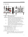
4.2 Rear Panel
(1) REMOTE I/O PORT 1: The remote input/output port 1.
START
: Start test signal input terminal.
STOP
: Stop test signal input terminal.
INTER LOCK : Output high voltage only when this two terminals are short-circuited.
UNDER TEST : When the tester is under testing, this output terminal will be
short-circuited. Control external signal by using this short condition.
The junction specification 30V AC or 60V DC current is less than 0.3A
action time. The tester is under testing until be stopped.
PASS
: When the tester judge DUT as pass, this output terminal will be
short-circuited. User specifies the time of short circuit. Control
external signal by using this short circuit condition. The junction
specification 30V AC or 60V DC current is less than 0.3A action time.
The product judge as pass until is stopped.
FAIL
: When the tester judge DUT as fail, this output terminal will be
short-circuited. Control external signal by using this short circuit
condition. The junction specification 30V AC or 60V DC current is less
than 0.3A action time. The product judge as fail until is stopped.
(2) VOLTAGE SELECTOR: Input Power Range Switch
Change the tester inputted AC power. AC power by using has below four kinds.
a. 110V applicable voltage range 90 ∼ 110V AC
b. 120V applicable voltage range 100 ∼ 130V AC
c. 220V applicable voltage range 200 ∼ 240V AC
d. 240V applicable voltage range 220 ∼ 250V AC
As changing this power switch, please notice replacement of fuse.
(3) AC LINE: AC power socket and fuse holder.
A tri-cord power and fuse holder. Input AC power the tester needed from
AC power socket. The detailed specification of using fuse, please refers
“Chapter 3 – Notices before Using” or descriptions of rear panel in this
manual.
4-3
Ground Bond Tester 19572 User’s Manual
(4) GROUND: Safety ground terminal, please use applicable implement to connect this
ground terminal actually. If there is no grounded to earth actually, the
circuit or other instruments connection line with ground terminal is
short-circuit. The chassis of tester may exist high voltage. This is very
dangerous, anyone touch the tester under the above state may cause shock
hazard. Therefore, please be sure to connect safety ground terminal to
earth.
(5) RS232 INTERFACE:
This socket is for RS232 interface. GPIB and RS232 interface can’t use
simultaneously.
(6) FAN : The temperature controlled fan, as temperature reaches 50°C, fan opens
automatically. When the temperature is lower than 45°C, fan stops
automatically.
(7) REMOTE I/O PORT 2: The remote input/output port 2.
All functions of 9pin D-Sub connector are the same as (1) Remote I/O port 1.
(8) Terminal Area of Rear Panel
The function of this area is the same as terminal area on front panel.
(9) OPTION INTERFACE
This interface is for the users to purchase GPIB CARD or PRINTER CARD.
GPIB CARD can use computer by GPIB (IEEE 488-1978) interface to remote control and
data transfer. PRINTER CARD can plug in CENTRONICS PORT printer with DOS
support mode direct to print test parameters and results of the tester.
4.3
Notices and Procedures before Operation
1. Before plug in AC power cord, please confirm power used is meet to marked power on
the rear panel firstly and power switch is OFF status.
2. Before power on, please peruse “Chapter 3 – Notices before Using” and memorize it.
3. When power on, the tester will self-test. If there is abnormal condition, please turn off
switch and pull off power cord immediately.
4-4
Panel Description
4.4
SYSTEM Setup
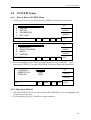
4.4.1 How to Enter SYSTEM Menu
1. Under power on screen, press Function Key [MENU] to display the menu below:
1.
2.
3.
4.
5.
UP
MEMORY
SYSTEM
OPTION
CALIBRATION
KEY LOCK
DOWN
SELECT
SELECT FUNC.
6.
7.
8.
9.
10.
RMT
LOCK
OFST ERR
UP
CHANGE PASSWORD
ERROR LOG
PRINT PROGRAM
ABOUT
VERSION
SELECT FUNC.
EXIT
DOWN
SELECT
RMT
LOCK
OFST ERR
EXIT
2. Move the highlight to “SYSTEM” by using Function Key [UP], [DOWN]. Press
Function Key [SELECT] to enter SYSTEM SETUP menu, display the menu below:
1.CONTRAST
2.BEEPER VOL.
3.PASS ON
:
:
:
UP
11
HIGH
CONT.
DOWN
ENTER
1-16
RMT
LOCK
OFST ERR
EXIT
4.4.2 Operation Method
1. Enter SYSTEM SETUP screen, press function Key [ENTER] to move the highlight to the
parameter you want to set.
2. Press function Keys [UP], [DOWN] to set this parameter.
4-5
Ground Bond Tester 19572 User’s Manual
System parameter setting description table
Setting Item
Range
Contrast
1∼16
Beeper Vol.
LOW / MEDIUM /
HIGH / OFF
Pass ON
0, 0.1 ∼ 99.9 s
(0: CONT.)
4.5
Initial Setting
7
HIGH
CONT.
Description
Adjust LCD brightness
Adjust buzzer volume
When test result is PASS,
sets the time of “Pass
Relay ON” on rear panel.
Memory Management
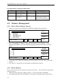
4.5.1 How to Enter Memory Process
1. In power on menu, press Function Key [MENU] to display the menu below:
1.
2.
3.
4.
5.
UP
MEMORY
SYSTEM
OPTION
CALIBRATION
KEY LOCK
SELECT FUNC.
DOWN
SELECT
RMT
LOCK
OFST ERR
EXIT
2. Move the highlight to “Memory” by using Function Key [UP], [DOWN]. Press
Function Key [SELECT] to enter Memory management mode and is shown as below
menu.
1.
2.
3.
4.
5.
STORE
(0)
(0)
(0)
(0)
(0)
SELECT FUNC.
RECALL
DELETE
RMT
LOCK
OFST ERR
EXIT
3. At the same time, follows the instruction of Function Key can recall, store or delete this
memory.
4. The value in ( ) means the test step numbers included in the memory.
4.5.2 Delete Memory
If you want to delete the test parameter stored in the memory. Please follow the procedures
below to process.
1. When the status list shows “SELECT FUNC.”, press Function Key [DELETE].
2. By using Function Key [UP], [DOWN] to select the test parameter data of the memory
4-6
Panel Description
which want to delete. Press Function Key [SELECT] will show a delete confirmation
screen.
3. Press Function Key [YES] to confirm or press Function Key [NO] to cancel.
4.5.3 Recall Memory
If there are a lot of test parameter values in the main memory. Follow the below procedures
to recall test parameter.
1. When the status list shows “SELECT FUNC.”, press Function Key [RECALL].
2. By using Function Key [UP], [DOWN] to select the test parameter data of the memory
which want to recall.
3. Press Function Key [SELECT] will show a recall confirmation window.
4. Press Function Key [YES] to confirm or press Function Key [NO] to cancel.
4.5.4 Store Memory
If you want to store the test parameter set in the memory. Please follow the procedures
below to process.
1. When the status list shows “SELECT FUNC.”, press Function Key [STORE] .
2. By using Function Key [UP], [DOWN] to select the memory which want to store. Press
Function Key [SELECT] the highlight becomes a blinking underline.
3. By using Function Key [UP], [DOWN] to input the memory name in the meantime.
4. By using Function Key [ENTER] to move the blinking underline highlight to the next
position of character.
5. If press Function Key [ENTER] twice continuously, and then will show a store
confirmation window.
6. Press Function Key [YES] to confirm or press Function Key [NO] to cancel.
(Note: If there is data in the memory, it will be overlapped. Please confirm carefully
before store.)
4.6
PRESET Testing
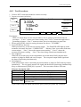
4.6.1 How to Enter PRESET Setting Menu
1. In power on menu, press Function Key [PRESET] then enter PRESET setting menu, the
menu display as below:
1.PASS HOLD
2.STEP HOLD
3.JUDG. WAIT
4.GB FREQ.
5.GB VOLTAGE
0.2-99.9
:
:
:
:
:
0.5
0.2
0.3
60
8.0
RMT
UP
sec
sec
sec
Hz
V
LOCK
DOWN
ENTER
OFST
ERR
EXIT
4-7
Ground Bond Tester 19572 User’s Manual
4.6.2 Operation Method
1. After entering PRESET menu, move the highlight to the parameter you want to set by
pressing [ENTER].
2. Press Function Keys [UP] or [DOWN] to set the parameter.
Test preset parameter functions table:
Setting Item
Range
PASS HOLD 0.2 ∼ 99.9
Initial Setting
Description
0.5
When the test result is PASS, set the
continuous time of buzzer beeps.
STEP HOLD 0 ∼ 99.9 / 0 = KEY 0.2
Set interval time between test procedures.
Key: Set test procedure interrupted (Please
press [START] to continue when test stop.)
JUDG. WAIT 0.1 ∼ 99.9
0.3
Set no judgment time
GB FREQ.
50/60
60
Set output voltage frequency when grounds
continue testing.
GB VOLTAGE 1 - 8
8
Set output voltage when grounds continue
testing.
SOFT. AGC
ON/OFF
ON
Set if software auto gain compensation
function is open.
FAIL CONT. ON/OFF
OFF
Set if continue the next step after
happening NG.
SCREEN
ON/OFF
ON
Set if show the test screen.
SMART KEY ON/OFF
OFF
Set if open the function of parameter
memory.
START WAIT 0-99.9/0=OFF
OFF
Set the waiting time of starting test.
PART NO.
Maximum 13
NONE
Set the part number of the product.
characters
LOT NO.
Maximum 13
NONE
Set the lot number of the product.
characters
SERIAL NO. Maximum 13
NONE
Set the serial number of the product, *
characters
means universal character. The minimum
is 5 characters, and can’t all be *.
4-8
Panel Description
4.7
PROGRAM Setting
4.7.1 Test Procedure Setting
1. In power on menu, press Function Key [PROGRAM] then enter PROGRAM setting
menu, the menu display as below:
STEP 1
CURR:
HIGH:
TIME:
GB
LOW :
OFF
UP
3.00A
500mΩ
3.0s
PROCESS STEP
MORE..
ENTER
RMT
LOCK
OFST ERR
EXIT
2. Enter PROGRAM setting menu, the test procedures increase by using Function Key
[UP], the range is from 1∼99.
3. Press [ENTER] to move the highlight to the other parameter want to set.
4. Can switch Function Key menu by using Function Key [MORE..], as shown below:
STEP 1
CURR:
HIGH:
TIME:
GB
LOW : OFF
DELETE
3.00A
500mΩ
3.0s
PROCESS STEP
INSERT
DOWN
RMT
LOCK
OFST ERR
MORE..
5. By using Function Key [DOWN] can decrease the test step want to set, the range is 1∼99.
6. By using Function Key [DELETE] and [INSERT] can delete and insert a test step.
7. Press Function Key [MORE..] can return to the previous Function Key menu, and
continue to set the other test parameter.
4.7.2 Operation Method
1. Enter PROGRAM setting menu, move the highlight to the parameter you want to set by
pressing [ENTER].
2. Press Function Key [UP] or [DOWN] to set the parameter.
4-9
Ground Bond Tester 19572 User’s Manual
4.7.3 Each Parameter Setting Data Description
The following are the parameter setting data of each test mode.
Ground resistance test mode (GB)
STEP 1
CURR:
HIGH:
TIME:
3.00-45.0A
CURR
Note
HIGH
LOW
TIME
4.8
GB
LOW :
OFF
UP
3.00A
100mΩ
3.0s
DOWN
ENTER
RMT
LOCK
OFST ERR
EXIT
: Set ground resistance test needed current.
: Because the test current multiply the high limit of resistance can’t more than
6.3V. High limit of resistance will be auto modify to adaptable value when it
isn’t correspondence with the above condition.
: Set ground resistance high limit value, the value is 510mΩ or minor value in
6.3V/ CURRENT.
: Set ground resistance low limit value, the value is less than high limit value of
ground resistance or OFF.
: Set test needed time, input 0 means continuous test.
How to Process Test
4.8.1 Offset Value Calibration of Test Cable
1. In power on menu, enter multi-groups STEPS test menu by pressing Function Key
[MORE..] .
2. Press Function Key [OFFSET], the display will show the menu to indicate the user to
connect the test cable of grounding test applicable to (+), (-) two terminals of DRIVE and
SENSE, then short-circuit the test cable.
3. Press [START], DANGER LED lights on front panel. The current output time is the
users’ setting test time. If the test time is CONT., the current output time is five seconds.
The main system start to measure line resistance of test cable and show the value on the
display then store in the memory.
4.8.2 Connecting DUT Methods
Ground resistance test mode (GB)
First of all, confirms there is no current output and DANGER LED isn’t light, screws the test
cable and terminal up by using tool and then clipping DUT by test cable.
4-10
Panel Description
4.8.3 Test Procedures
1. Follows DUT connection method to connect correctly.
2. In power on menu (as below),
Line 1
Line 2
Line 3
STEP 1/2
GB
3.00A
100mΩ
3.0s
LOW :
0.1mΩ
PROGRAM
PRESET
MENU
RMT
LOCK OFST ERR
MORE..
Description:
STEP 1/2 means there are two test procedures, now is going to perform the first test
procedure. “Line 1” means test current setting value, “Line 2” means the high limit of
grounding resistance, “Line 3” means test time, the test result shows on status line.
1. Please press [STOP] ready for testing, the status line shows ” STANDBY”.
2. Press [START] to start test.
When press this key, it will start test current output. The DANGER LED light up in the
meantime, the status line show “ UNDER TEST”. Warning: Now is test status with mass
current output. “Line 1” shows the output current reading. “Line 2” shows the
measured resistance reading. “Line 3” the timer doing count down simultaneously.
3. Pass judgment
When all of test states have been tested and the test result shows PASS, then the main
machine is judged as PASS and cut off output. The rear panel output PASS signal and
the buzzer functioning simultaneously.
4. Fail judgment
If the measurement value is abnormal, the main machine is judged as FAIL and stop output
immediately. The rear panel output FAIL signal and the buzzer functioning simultaneously.
Keep on function until [STOP] key is pressed. The test result will show Fail state.
Fail state description table
Test result
Meaning
HI
Measurement resistance value is over high limit
LO
Measurement resistance value is over low limit
ADV OVER
Current reading is over hardware valid digit.
ADI OVER
Resistance reading is over hardware valid digit.
Do not set the output current value or the measured resistance
CAN NOT TEST
high limit value.
If you want to stop test output only need to press [STOP] key under any condition.
4-11
Ground Bond Tester 19572 User’s Manual
4.9 KEY LOCK Function
4.9.1 KEY LOCK Setting
1. In Power On Menu, you can set KEY LOCK if “ LOCK” is not highlighted.
2. Press Function Key [MENU], the menu shown below.
1.
2.
3.
4.
5.
UP
MEMORY
SYSTEM
OPTION
CALIBRATION
KEY LOCK
SELECT FUNC.
DOWN
SELECT
RMT
LOCK
OFST ERR
EXIT
3. Use Function Key [UP] and [DOWN] to move the highlight to “ KEY LOCK”, and press
Function Key [SELECT] to enter KEY LOCK setting menu.
4. Use Function Key [A] and [B] to input the PASSWORD (default is AAAA.)
5. Press [ENTER] will prompt a selection window, and “LOCK” is highlighted. The user
can press Function Key [YES] or [NO] to select if lock the MEMORY RECALL function
as well.
4.9.2 Canceling KEY LOCK
1. In Power On Menu, you can release KEY LOCK if ”LOCK” is highlighted.
2. Press Function Key [MENU], the menu shown below:
1.
2.
3.
4.
5.
UP
MEMORY
SYSTEM
OPTION
CALIBRATION
KEY LOCK
SELECT FUNC.
DOWN
SELECT
RMT
LOCK
OFST ERR
EXIT
3. Move the highlight to “KEY LOCK” by using Function Key [UP] and [DOWN].
Function Key [SELECT] to enter KEY LOCK release menu.
Press
4. Use Function Key [A] and [B] to input the PASSWORD (default is AAAA).
5. Press Function Key [ENTER], ”LOCK” will not be highlighted means KEY LOCK
function has cancelled.
4-12
Panel Description
4.10 User Password Setting
1. In Power On Menu, press Function Key [MENU] to show the menu below:
1.
2.
3.
4.
5.
UP
MEMORY
SYSTEM
OPTION
CALIBRATION
KEY LOCK
SELECT FUNC.
DOWN
SELECT
RMT
LOCK
OFST ERR
EXIT
2. Use Function Key [UP] and [DOWN] to move the highlight to “CHANGE PASSWORD”
and press Function Key [SELECT] to enter the password menu.
3. Use Function Key [A] and [B] to input the OLD PASSWORD (default is AAAA). After
pressing [ENTER], use Function Key [A] and [B] to input NEW PASSWORD (the
maximum is 10 characters). After pressing [ENTER], use Function Key [A] and [B] to
input CONFIRM PASSWORD (same as NEW PASSWORD) and press Function Key
[ENTER]. Press [EXIT] after completing the setting.
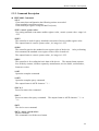
4.11 Remote Control
The REMOTE outlet for remote control switch is located at the rear panel. You can plug in
the control line to use external signal for controlling the device output externally.
Be aware when using remote control as it is done by external signal and using carefully to
avoid the tester error operation to cause any danger. Other control circuit usually does
remote control. Be careful that it is the switch to control the mass current output, so you
must connect the control line do not get near the power terminal and noise to avoid causing
any danger.
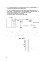
1. For single control of START and STOP signals follow Figure 4-5 listed below to connect
them to the REMOTE position on front panel of the main system.
Figure 4-5
Figure 4-6
4-13
Ground Bond Tester 19572 User’s Manual
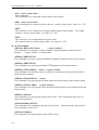
2. If it is connected as Figure 4-6 shows, the system routine is in STOP state as the NC is
connected to STOP and NO is connected to START.
3. The logic components of transistor, FET and couplers can be connected and used as
control circuit. The connected signals and circuit are shown as Figure 4-7 below. To
use this circuit to control the system, it must contain the following:
(1) The current of LOW signal is 2mA or less.
(2) The active time for input signal is more than 20mS.
Figure 4-7
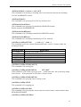
4. Either the relay switch control in Figure 4-5 or the coupler control in Figure 4-7 uses the
contact of components for control action. It can prevent the error operation from
interference effectively. Though the system has a lot of precautions, you would still
need to watch out the interference caused by the measurement system settings.
5. The pin assignment of REMOTE CONTROL is shown as figure 4-8 below.
memorized when using external control.
It should be
Figure 4-8
Pin assignment print on the
surface of rear panel.
4-14
Panel Description
4.12 Output Signal
This instrument has indicator and beeper for indication signals. The output signals in the
system rear panel are:
UNDER TEST : This terminal will be short circuited when in test state, thus it can be
used to control the external signal. The connection point specification
is 30V AC or 60V DC, the current is less than 0.3A.
PASS
: This terminal will be short circuited when the DUT passes the tests, the
user specifies the time of short circuit and it can be used to control the
external signal. The connection point specification is 30V AC or 60V
DC, the current is less than 0.3A. The action time is from the DUT is
passed until it is stopped.
FAIL
: This terminal will be short circuited when the DUT fails the tests, thus it
can be used to control the external signal. The connection point
specification is 30V AC or 60V DC, the current is less than 0.3A. The
action time is from the DUT is failed until it is stopped.
4-15
Remote Interface Description
5. Remote Interface Description
5.1 RS232 Interface Specification
5.1.1 Data Format
Baud Rate: 300 / 600 / 1200 / 2400 / 4800 / 9600 / 19200
Parity: NONE / ODD / EVEN
Flow Control: NONE / SOFTWARE
Transmit bit: 1 initial bit
8 data bit or 7 data bit add 1 parity bit
1 end bit
5.1.2 Command Format
The RS232 interface function of the instrument is inputted by ASCII code to compose
command string to remote control and setting function. The length limit of command string
is within 1024 characters (include end code) [command + parameter] to compose a command.
Two commands can connect by semicolon “;” and add end code finally. End code can be
any type of the below. The instrument can distinguish by itself.
End code
LF
CR + LF
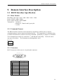
5.1.3 Connector
RS232 connector of this tester is a 9-pin female connector.
5 4 3 2 1
9 8 7 6
Pin No.
1
2
3
4
5
6
7
8
9
*
TxD
RxD
*
GND
*
*
*
*
Description
Not used
Deliver data
Receive data
Not used
Grounding
Not used
Not used
Not used
Not used
5-1
Ground Bond Tester 19572 User’s Manual
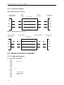
5.1.4 Connection Method
DB-9 to DB-9 Serial Connection
9 Pin
(male)
9 Pin (female)
Instrument
TxD
RxD
GND
Link cable
9 Pin
(female)
9 Pin (male)
PC
2
2
2
2
3
3
3
3
5
5
5
5
RxD
TxD
GND
DB-9 to DB-25 Serial Connection
9 Pin (female)
9 Pin (male)
RxD
GND
2
2
3
3
3
3
2
2
5
5
7
7
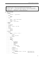
5.2 Remote Interface Command
5.2.1 Command Summary
IEEE 488.2 Command
*CLS
*ESE
*ESE?
*ESR?
*IDN?
*OPC
*OPC?
*PSC
*PSC?
*RST
*RCL
*SAV
*SRE
*SRE?
*STB?
5-2
25 Pin (male)
PC
Link cable
Instrument
TxD
25 Pin (female)
< enable value >
0|1
< register number >
< register number >
< enable value >
RxD
TxD
GND
Remote Interface Description
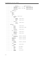
The parameter syntax format of SCPI command includes the following.
Dual arrow symbol “< >” denote the defined parameter of SCPI command standard.
“< numeric_value >” is metric system value, “<boolean>” is Boolean equation data and
its’ value is 0 or 1. Vertical line ” | “ denotes OR parameter.
SCPI Command
:MEMory
| :DELete
| |
:LOCAtion
| :FREE
| |
:STATe?
| |
:STEP?
| :STATe
< register number >
| |
:DEFine <name>,<register number>
| |
:DEFine? <name>
| |
:LABEl? < register number >
| NSTates?
:SYSTem
| :ERRor
| |
[NEXT]?
| :VERSion?
| :KLOCk < boolean >|ON|OFF
| :KLOCk?
| :LOCK
| |
:OWNer?
| |
:REQuest?
| |
:RELease
[:SOURce]
| :SAFEty
|
|
:FETCh? [ < item > ] { , < item > }
| |
:STARt
| |
|
[:ONCE]
| |
|
:OFFSet GET | OFF
|
|
|
:OFFSet?
|
|
:STOP
|
|
:STATus?
|
|
:SNUMber?
|
|
:RESult
|
|
|
:ALL
|
|
|
|
[:JUDGment]?
|
|
|
|
:OMETerage?
|
|
|
|
:MMETerage?
|
|
|
|
:MODE?
|
|
|
|
:TIME
|
|
|
|
|
[:ELAPsed]
|
|
|
|
|
|
[:TEST]?
|
|
|
:COMPleted?
|
|
|
[:LAST]
|
|
|
|
[:JUDGment]?
|
|
|
:AREPort
|
|
|
|
[:JUDGment]
|
|
|
|
| [:MESsage] < boolean >|ON|OFF
|
|
|
:AREPort
|
|
|
|
[:JUDGment]
(RS232 interface only)
(RS232 interface only)
5-3
Ground Bond Tester 19572 User’s Manual
|
|
|
|
|
|
|
|
|
|
|
|
|
|
|
|
|
|
|
|
|
|
|
|
|
|
|
|
|
|
|
|
|
|
|
|
|
|
|
|
|
|
|
|
|
|
|
|
|
|
|
|
|
|
|
5-4
|
|
|
|
|
|
|
|
|
|
|
|
|
|
|
|
|
|
|
|
|
|
|
|
|
|
|
|
|
|
|
|
|
|
|
|
|
|
|
|
|
|
|
|
|
|
|
|
|
|
|
|
|
|
|
|
|
| [:MESsage] ?
(RS232 interface only)
|
|
:OMETerage < boolean >|ON|OFF
(RS232 interface only)
|
|
:OMETerage?
(RS232 interface only)
|
|
:MMETerage < boolean >|ON|OFF (RS232 interface only)
|
|
:MMETerage?
(RS232 interface only)
|
:ASTart
|
|
:STATus?
:STEP<n>
|
:DELete
|
:SET?
|
:MODE?
|
:GB
|
|
[:LEVel] < numeric value >
|
|
[:LEVel]?
|
|
:LIMit
|
|
|
[:HIGH] < numeric value >
|
|
|
[:HIGH]?
|
|
|
:LOW
< numeric value >
|
|
|
:LOW?
|
|
:TIME
|
|
|
[:TEST] < numeric value >
|
|
|
[:TEST]?
:PRESet
|
:TIME
|
|
:PASS
< numeric value >
|
|
:PASS?
|
|
:STEP
< numeric value > | KEY
|
|
:STEP?
|
|
:JUDGment
< numeric value >
|
|
:JUDGment?
|
:GB
|
|
:FREQuncy
< numeric value >
|
|
:FREQUery?
|
|
:VOLTage
< numeric value >
|
|
:VOLTage?
|
:AGC
|
|
[:SOFTware]
<boolean > | ON | OFF
|
|
[:SOFTware]?
|
:FCONtinuity
<boolean > | ON | OFF
|
:FCONtinuity?
|
:SCREen
<boolean > | ON | OFF
|
:SCREen?
|
:KEYboard
|
|
:SMARt
<boolean > | ON | OFF
|
|
:SMARt?
|
:TIME
|
|
:ASTart
< numeric value >
|
|
:ASTart?
|
:NUMber
|
|
:PART
<part number>
|
|
:PART?
|
|
:LOT
<lot number>
|
|
:LOT?
|
|
:SERIal
<serial number>
|
|
:SERIal?
Remote Interface Description
5.2.2 Command Description
IEEE 488.2 Command
*CLS
Clear status data configuration the following actions are needed.
Clear standard event status register
Clear status byte register except for MAV bit (bit 4).
*ESE < metric system value>
Use setting standard event status enables register value, <metric system value> range is 0
∼255.
*ESE?
The controller is used for query standard event status of device enable register value.
The output format is <metric system value>, its’ range is 0 ∼255.
*ESR?
The controller queries the standard event register value of the device.
this command, the standard event register value will be cleared to 0.
The output format is <metric system value>, its’ range is 0 ∼255.
After performing
*IDN?
The controller is for reading the basic data of the device. The output format separate
four fields by comma, it denote separately: manufacturer, device model, serial number.,
firmware version.
*OPC
Operation complete command
*OPC?
Operation complete query command
The output format is ASCII character ” 1 “.
*PSC 0 | 1
Power on status clear command
*PSC?
Power on status clear query command.
” 0 “.
The output format is ASCII character ” 1 “ or
*RST
The device reset command.
*RCL < metric system value>
Recall command
This command is recall the saved status.
5-5
Ground Bond Tester 19572 User’s Manual
*SAV < metric system value>
Save command
This command is for saving the current status to the memory.
*SRE < metric system value>
It is for setting service request register value, its’ <metric system value> value is 0 ∼ 255.
*SRE?
The controller is for reading service request enable register initial setting. The output
format is <metric system value>, its’ range is 0 ∼255.
*STB?
The controller is for reading status bit register value.
The output format is <metric system value>, its’ range is 0 ∼255
SCPI Command
:MEMory:DELete:LOCAtion
< register number >
This command is for deleting < register number > denoted parameter data in system
memory. < register number > is integral data.
:MEMory:FREE:STATe?
This command is for query remainder PRESET parameter quantity in the system memory.
:MEMory:FREE:STEP?
This command is for querying remainder STEP quantity in the system memory.
:MEMory:STATe:DEFine <name>, <register number>
This command is for defining a name to a memory located at a certain specified position
inside the main memory.
:MEMory:STATe:DEFine? <name>
This command is for querying the location inside the main memory by the memory name.
:MEMory:STATe:LABEl? < register number >
This command is for querying the name inside the main memory by the location inside the
main memory.
:MEMory:NSTates?
This command is for querying the main system *SAV / *RCL maximum value add 1 of
can be used parameter.
:SYSTem:ERRor[:NEXT]?
This command is for reading the message in error queue.
error messages in section 5.5.
:SYSTem:VERSion?
This command is for querying the system SCPI version.
5-6
Return message, please check
Remote Interface Description
:SYSTem:KLOCk < boolean > | ON | OFF
This command is for locking or releasing LOCAL key function, but not for switching
LOCAL and REMOTE control.
:SYSTem:KLOCk?
This command is for querying if LOCAL key locked or not.
:SYSTem:LOCk:OWNer?
This command is for querying if controlled by REMOTE terminal.
Return character NONE|REMOTE.
:SYSTem:LOCk:REQuest?
This command is for switching controlled by REMOTE terminal.
:SYSTem:LOCk:RELease
This command is for switching controlled by LOCAL terminal.
[:SOURce]:SAFEty:FETCh?
[ < item > ] [ , < item > ]
This command queries the system measurement result, <item> is character data, the
meaning as below:
Character Data
STEP
MODE
OMETerage
MMETerage
TELApsed
TLEFT
Return Data
The STEP serial number now.
The MODE now.
The output value now.
The measurement value now.
The TEST executed time now.
The TEST remains time now.
[:SOURce]:SAFEty:STARt[:ONCE]
This command is for starting test.
[:SOURce]:SAFEty:STARt:OFFSet
GET | OFF
If the parameter is GET, that is get zero value. At the same time, the system may output
mass current. If the parameter is OFF, that is off zero action.
[:SOURce]:SAFEty:STARt:OFFSet?
This command is for querying if does zeroing or not.
[:SOURce]:SAFEty:STOP
This command is for stopping test.
[:SOURce]:SAFEty:STATus?
This command is for querying the current system execution status, return character data
RUNNING|STOPPED.
[:SOURce]:SAFEty:SNUMber?
5-7
Ground Bond Tester 19572 User’s Manual
This command is for querying setting STEP number in the memory.
[:SOURce]:SAFEty:RESult:ALL:OMETerage?
This command is for querying OUTPUT METER reading of all steps.
[:SOURce]:SAFEty:RESult:ALL:MMETerage?
This command is for querying MEASURE METER reading of all steps.
[:SOURce]:SAFEty:RESult:ALL:MODE?
This command is for querying MODE of all steps, it will return character data GB.
[:SOURce]:SAFEty:RESult:ALL:TIME[:ELAPsed][:TEST]?
This command is for querying test time of all steps.
[:SOURce]:SAFEty:RESult:ALL[:JUDGment]?
This command is for querying all judgment result. Return format: First Step Result,
Second Step Result, ..., Last Step Result. Code meaning as below table:
Test result code table:
Mode
Code
STOP
USER STOP
CAN NOT TEST
TESTING
PASS
HIGH FAIL
LOW FAIL
OUTPUT A/D OVER
METER A/D OVER
GB
HEX DEC
70 112
71 113
72 114
73 115
74 116
11
17
12
18
16
22
17
23
[:SOURce]:SAFEty:RESult:COMPleted?
This command is for querying the system if complete execution action or not, return 1 or 0.
[:SOURce]:SAFEty:RESult[:LAST][:JUDGment]?
This command is for querying judgment result code of last STEP.
The judgment result code table:
Result
PASS
USER STOP
CAN NOT TEST
TESTING
STOP
5-8
Code (hexadecimal)
74
71
72
73
70
Code (metric system)
116
113
114
115
112
Remote Interface Description
The judgment result fail code table:
GB MODE
Hex Dec
HI
11
17
LO
12 18
ADV OVER 16
22
ADI OVER 17
23
[:SOURce]:SAFEty:RESult:AREPort[:JUDGment][:MESsage]< boolean > | ON | OFF
This command is for setting if auto report the test result. When set as ON, the test is
completed then return “PASS” or “FAIL” string data. (RS232 interface only)
[:SOURce]:SAFEty:RESult:AREPort[:JUDGment][:MESsage]?
This command is for querying if auto report the test result, return 1 or 0 (RS232 interface only).
[:SOURce]:SAFEty:RESult:AREPort:OMETerage < boolean > | ON | OFF
This command is for setting if auto report the test result. When set as ON, the test is
completed then return the output current value of all STEPs. If some STEPs don’t be
tested, there is without output value. These STEPs return is +9.910000E+37 (RS232
interface only).
[:SOURce]:SAFEty:RESult:AREPort:OMETerage ?
It queries the output current if auto report the test result, return 1 or 0 (RS232 interface only).
[:SOURce]:SAFEty:RESult:AREPort:MMETerage < boolean > | ON | OFF
It sets the measurement value if auto report the test result. When set as ON, the test is
completed then return the measurement value of all STEPs. If some STEPs don’t be
tested, there is without measurement value. These STEPs return is +9.910000E+37
(RS232 interface only).
[:SOURce]:SAFEty:RESult:AREPort:MMETerage ?
It queries the measurement value if auto report the test result, return 1 or 0 (RS232 interface only).
[:SOURce]:SAFEty:RESult:ASTart:STATus?
This command is for querying GBSS MODE status, return character data ON|OFF.
[:SOURce]:SAFEty:STEP<n>:DELete
This command will delete STEP of <n> represented, the next STEP of <n> will fill it.
[:SOURce]:SAFEty:STEP<n>:SET?
This command is for querying all setting values in selected STEP.
[:SOURce]:SAFEty:STEP<n>:MODE?
This command is for querying MODE in selected STEP, it will return character data GB.
[:SOURce]:SAFEty:STEP<n>:GB[:LEVel]
< numeric value >
This command is for setting selected STEP, ground resistance test needed current value,
the unit is ampere (A).
5-9
Ground Bond Tester 19572 User’s Manual
[:SOURce]:SAFEty:STEP<n>:GB[:LEVel]?
This command is for querying selected STEP, ground resistance test needed current value.
[:SOURce]:SAFEty:STEP<n>:GB:LIMit[:HIGH] < numeric value >
This command is for setting selected STEP, ground resistance judgment high limit, the
unit is Ohm.
[:SOURce]:SAFEty:STEP<n>:GB:LIMit[:HIGH]?
This command is for querying selected STEP, ground resistance judgment high limit.
[:SOURce]:SAFEty:STEP<n>:GB:LIMit:LOW
This command is for setting selected STEP, ground resistance judgment low limit.
[:SOURce]:SAFEty:STEP<n>:GB:LIMit:LOW?
This command is for querying selected STEP, ground resistance judgment low limit.
[:SOURce]:SAFEty:STEP<n>:GB:TIME[:TEST] < numeric value >
This command is for setting selected STEP, its’ test needed time; the unit is second (s).
[:SOURce]:SAFEty:STEP<n>:GB:TIME[:TEST]?
This command is for querying selected STEP, its’ test needed time.
[:SOURce]:SAFEty:PRESet:TIME:PASS < numeric value >
This command is for setting BUZZER beeps time when passes the test.
<numeric_value> is a value between 0.2 and 99.9(included).
[:SOURce]:SAFEty:PRESet:TIME:PASS?
This command is for querying BUZZER beeps output continuous time when passes the
test. It returns a value between 0.2 and 99.9(included).
[:SOURce]:SAFEty:PRESet:TIME:STEP < numeric value > | KEY
This command is for setting interval time between STEP, and the next time to start
command to execute the next STEP.
[:SOURce]:SAFEty:PRESet:TIME:STEP?
This is for querying interval setting between steps, return value is KEY or the value of
unit is second.
[:SOURce]:SAFEty:PRESet:TIME:JUDGment < numeric value >
This command is for setting a period of time, a certain of conditions do not detect.
[:SOURce]:SAFEty:PRESet:TIME:JUDGment?
This command is for querying the time of waiting detection.
[:SOURce]:SAFEty:PRESet:GB:FREQuency < numeric value >
This command is for setting ground impedance test output current frequency.
[:SOURce]:SAFEty:PRESet:GB:FREQuency?
5-10
Remote Interface Description
This command is for querying ground impedance test output current frequency.
[:SOURce]:SAFEty:PRESet:GB:VOLTage < numeric value >
This command is for setting ground impedance test open voltage.
[:SOURce]:SAFEty:PRESet:GB:VOLTage?
This command is for querying ground impedance test open voltage.
[:SOURce]:SAFEty:PRESet:AGC[:SOFTware]
< boolean > | ON | OFF
This command is for setting software AGC is open or not.
[:SOURce]:SAFEty:PRESet:AGC[:SOFTware]?
This command is for querying software AGC is open or not. Return character is 1 or 0.
[:SOURce]:SAFEty:PRESet:FCONtinuity < boolean > | ON | OFF
This command is for setting if continue to test the next step when fails the test.
[:SOURce]:SAFEty:PRESet:FCONtinuity?
This command is for querying if FCONtinuity is open or not. It returns character 1 or 0.
[:SOURce]:SAFEty:PRESet:SCREen < boolean > | ON | OFF
This command is for setting the test screen is ON or OFF.
[:SOURce]:SAFEty:PRESet:SCREen?
This command is for querying the test screen is ON or OFF.
It returns character 1 or 0.
[:SOURce]:SAFEty:PRESet:KEYboard:SMARt < boolean > | ON | OFF
This command is for setting SMART KEY is open or not.
[:SOURce]:SAFEty:PRESet:KEYboard:SMARt?
This command is for querying SMART KEY is open or not.
It returns character 1 or 0.
[:SOURce]:SAFEty:PRESet:TIME:ASTart < numeric value >
This command is for setting the time of waiting to start of GBSS MODE.
range is 0.1~99.9 second. When set to 0, it means GBSS MODE is off.
The setting
[:SOURce]:SAFEty:PRESet:TIME:ASTart?
This command is for querying the time of waiting to start of GBSS MODE.
[:SOURce]:SAFEty:PRESet:NUMber:PART <part number>
This command is for setting part number.
[:SOURce]:SAFEty:PRESet:NUMber:PART?
This command is for querying part number.
[:SOURce]:SAFEty:PRESet:NUMber:LOT
This command is for setting lot number.
<lot number>
[:SOURce]:SAFEty:PRESet:NUMber:LOT?
5-11
Ground Bond Tester 19572 User’s Manual
This command is for querying lot number.
[:SOURce]:SAFEty:PRESet:NUMber:SERIal
<serial number>
This command is for setting serial number format of product, * means universal character.
[:SOURce]:SAFEty:PRESet:NUMber:SERIal?
This command is for querying serial number format of product.
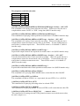
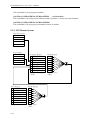
5.2.3 SCPI Status System
Error/Event Queue
Output Buffer
Summary Register
Not Used
1 Has Result
2 Error/Event Queue
Not Used
4 Message Available
5 Request Service
6 Request Service
Not Used
Serial Poll(SPOLL)
*STB?
Event Register
0 Operation Complete
Not Used
2 Query Error
3 Device Error
4 Execution Error
5 Command Error
Not Used
7 Power On
*ESR?
5-12
Enable Register
*ESE<value>
*ESE?
Enable Register
*SRE <value>
*SRE?
Remote Interface Description (Option)
5.3 Error Messages
Error messages are saved in error queue which access by FIFO method. The return
first error message is the first being saved.
When the error message is over 30, the last position would be saved as -350, ”Queue
overflow“. The error queue can’t save error message any more until there is error
message out.
When there is no error occurred, the first position would be saved +0,”No error”.
-102
-108
-109
-112
-113
-114
-151
-158
-170
-222
-291
-361
-365
-363
-400
-410
-420
Syntax error
Syntax error, usually includes not allowed character symbol in command.
Parameter not allowed
The device receives parameter is not allowed.
Missing parameter
Parameter is missed.
Program mnemonic too long
Simple command program header is over 12 characters.
Undefined header
The device is received undefined header.
Header suffix out of range
The header suffix is out of range.
Invalid string data
Invalid string data is usually missing double quotation.
String data not allowed
The device is received disallowed string data.
Expression error
The device is received uncompleted parameter data, such as missing the right
parenthesis.
Data out of range
The data is out of range.
Out of memory
The data is out of memory.
Parity error
The parity is error.
Time out error
The device isn’t received end character within a certain time.
Input buffer overrun
The device is received over 1024 characters.
Queue error
The output queue data is over 256 characters.
Query INTERRUPTED
When received a query command, you don’t read out the query result and then
received another query command immediately.
Query UNTERMINATED
There is no data in queue, meanwhile received the command of reading output queue
data.
5-13
Ground Bond Tester 19572 User’s Manual
5.4
RS232 Operation Using Basic
REM-----------------------------------------------------------------REM
RS232 example program
REM
Program compiled using Microsoft version 1.1(MS-DOS 6.22)
REM-----------------------------------------------------------------REM open serial port as device 1
OPEN "COM1:9600,N,8,1,RS,CS,DS,CD,LF" FOR RANDOM AS #1
PRINT #1, ":SOURce:SAFEty:STOP"
PRINT #1, ":SOURce:SAFEty:SNUMber ?"
INPUT #1, STEPNUM%
CLS
IF STEPNUM% > 0 THEN
FOR I = STEPNUM% TO 1 STEP -1
PRINT #1, "SOURce:SAFEty:STEP", I, ":DELete"'clear all steps data
NEXT I
END IF
PRINT #1, "SOURce:SAFEty:STEP1:GB:LEVel 3.1"
PRINT #1, "SOURce:SAFEty:STEP1:GB:LIMit:HIGH 0.2"
PRINT #1, "SOURce:SAFEty:STEP1:GB:TIME:TEST 3.1"
PRINT #1, "SOURce:SAFEty:STEP2:GB:LEVel 3.2"
PRINT #1, "SOURce:SAFEty:STEP2:GB:LIMit:HIGH 0.3"
PRINT #1, "SOURce:SAFEty:STEP2:GB:TIME:TEST 3.2"
SLEEP 1
PRINT #1, "SOURce:SAFEty:STARt"
'start test
PRINT #1, "SOURce:SAFEty:SNUMBer?"
INPUT #1, STEPNUM%
WHILE status$ <> "STOPPED"
PRINT #1, "SOURce:SAFEty:STATUS?"
INPUT #1, status$
'read status
IF status$ = "STOPPED" THEN
PRINT #1, "SOURce:SAFEty:STOP"
PRINT #1, "SAFEty:RESult:ALL:OMET?"
FOR j = 1 TO STEPNUM%
INPUT #1, result$
PRINT "step", j, ":", result$
NEXT j
PRINT
PRINT #1, "SAFEty:RESult:ALL:MMET?"
FOR j = 1 TO STEPNUM%
INPUT #1, result$
PRINT "step", j, ":", result$
NEXT j
END IF
5-14
'if status not=TEST
Remote Interface Description (Option)
WEND
PRINT #1, "SOURce:SAFEty:STOP"
CLOSE #1
END
5-15
GPIB Description (Option)
6.
GPIB Description (Option)
6.1
Guide
The user can use computer by GPIB (IEEE 488-1978) interface to remote control and data
transfer.
6.2
Interface Specification
6.2.1 Applicable Standard
IEEE488-1978 standard
6.2.2 Interface Capability
Code
SH1
AH1
T4
L4
SR1
RL1
PP0
DC1
DT0
C0
Meaning
Source Handshake
Equipped with source handshake interface function.
Acceptor Handshake
Equipped with acceptor handshake interface function.
Basic Talker requirement
Equipped with basic talker interface function.
Basic Listener requirement
Equipped with basic listener interface function.
Service request requirement
Equipped with service request interface function.
All remote/local requirement
Equipped with remote/local interface function.
No Parallel poll requirement
No parallel poll interface function.
All device clear requirement
Equipped with device clear interface function.
No Device trigger requirement
No device trigger interface function.
No controller requirement
No controller interface function.
6.2.3 Using Code
ASCII code.
6-1
Ground Bond Tester 19572 User’s Manual
6.3
GPIB Related Panel Description
6.3.1 Address Setting
1. Under power on menu, press Function Key MENU as the following shown:
1.
2.
3.
4.
5.
UP
MEMORY
SYSTEM
OPTION
CALIBRATION
KEY LOCK
SELECT FUNC.
DOWN
SELECT
RMT
LOCK
OFST ERR EXIT
2. Move the highlight to "OPTION" by Function Key UP , DOWN . Press Function Key
SELECT to enter OPTION selection setting as the following shown:
UP
1.RS232
2.GPIB
3.PRINTER
DOWN
SELECT
EXIT
RMT
LOCK
OFST ERR
3. Move the highlight to "GPIB" by Function Key UP , DOWN . Press Function Key
SELECT to enter GPIB setting menu as the following shown:
UP
1.GPIB ADDR.: 3
DOWN
ENTER
EXIT
RMT
LOCK
OFST ERR
4. Then select GPIB Address by Function Keys UP , DOWN .
5. The setting is completed, presses Function Key EXIT to exit.
6-2
GPIB Description (Option)
6.3.2 Remote / Local
1. The signal block Remote is highlighted, it means the tester is on Remote status.
2. On Remote status can use Function Key LOCAL to switch the tester to Local status.
3. On Remote status, all of panel keys are malfunction except for Function Key LOCAL
(switch to Local) MENU , MORE.. and STOP (reset instrument) keys.
4. By using LLO [Local lockout] command of GPIB makes LOCAL key malfunction.
6.4
Interface Message
The tester is capable of responding to the following interface messages.
Interface Signal
Meaning
Response
GTL
Go To Local
Can switch the tester to Local status.
SDC
Selected Device Clear Restart the analyzer
LLO
Local Lockout
From LOCAL key switch to Local status is forbidden.
IFC
Interface Clear
Reset GPIB interface.
6.5 GPIB Control / Setting Command Descriptions
The tester GPIB function composed command string is inputted by ASCII code to attain
functions of remote control and setting. The length of the command string is limited in 1024
characters (include end code) [Command + Parameter] compose a command. Two
commands can be connected by semicolon and ended by end code. The end code can be any
type of the following; the tester can distinguish by itself.
End code
LF
CR + LF
EOI
LF + EOI
CR + LF + EOI
Status response command
ÂCLS
ÂESE <enable value>
ÂESE?
ÂESR?
ÂSRE <enable value>
ÂSRE?
ÂSTB?
ÂPSC 0|1
ÂPSC?
6-3
Printer Function (Option)
7. Printer Function (Option)
Preface
The user can connect printer (any brand printer except for HP) to print test parameter setting
value or test result report.
How to print test parameter setting value?
1. Under power-on screen, press Function Key F3 MENU then move the cursor to 8. PRINT
PROGRAM.
2. Press Function Key F3 SELECT , connect the correct printer then will auto print out the
test parameter setting value in the memory.
How to print test result report?
After setting printer print parameter, follows normal test procedures to test. When test is
completed according to the user setting, connect the correct printer to print out test result
report.
Enter printer print parameter setting screen.
1. Under power-on screen, press Function Key MENU then move the cursor to 3. OPTION.
2. Press Function Key SELECT , then move the cursor to 3. PRINT.
3. Press Function Key F3 SELECT , then start to set print parameter.
How to set printer print parameter?
1. By using Function Keys UP , DOWN to set various parameter data.
2. By using Function Key ENTER to move the cursor.
3. By using Function Key EXIT to exit this screen.
Print parameter description:
A. AUTO PRINT - - includes the following two parameters for setting print test result report
timing.
1. PASS : OFF - - When setting is ON, the test result is PASS will print out the test
result report.
2. FAIL: OFF - - When setting is ON, the test result is FAIL will print out the test result
report.
3. F .FEED: OFF - - When setting is ON, end the print and printing paper will skip to
another page.
B. PRINT DATA - - Includes the following five parameters for setting print test result report
that includes data.
1. PART NO.: OFF -- When setting is ON, the test result report will print PART
NUMBER.
2. LOT NO.: OFF -- When setting is ON, the test result report will print LOT
NUMBER.
3. SERIAL NO.: OFF -- When setting is ON, the test result report will print SERIAL
NUMBER.
4. TEST DATA: OFF -- When setting is ON, the test result report will print STEP,
MODE and current/resistance data.
5. RESULT: OFF -- When setting is ON, the test result report will print the test result is
PASS or FAIL.
7-1
Calibration Procedure
8. Calibration Procedure
Calibration equipment:
1. Standard resistance 10m/100m/150m/500m Ω
2. Agilent 34401A Digital Multimeter or above
3. Yokogawa TYPE 2215 50A Current Shunt or above
Before process this section the tester should be warm up at least 30 minutes. Press the
calibration switch (CAL), it is equipped with hardware protection circuit to avoid calibration
data loss.
The following items are needed to calibrate:
GBA
45A
GBA
45A
GBVX1 8V
GBVX1 8V
GBVX10 8V
GBVX10 8V
CONTRAST
Offset (3A)
Full (30A)
Offset (0.3V)
Full (3V)
Offset (0.03V)
Full (0.3V)
VALUE
6
;GB current
;GB current
;GB voltage X1
;GB voltage X1
;GB voltage X10
;GB voltage X10
;Contrast Value
OFFSET
FULL
OFFSET
FULL
OFFSET
FULL
point
point
point
point
point
point
8.1 Calibration Menu
1. After powered on and initialized, press function key [MENU] [DOWN] [DOWN]
[DOWN] [SELECT] in sequence to enter CALIBRATION function. Display input
calibration password menu.
2. Press function key [A] [A] [A] [B] [SELECT] in sequence. Display calibration menu.
8.2 Start Calibration
Connect Yokogawa TYPE 2215 Current Shunt (50 mV, 50A, with four terminals) or
equivalent shunt to Sense and Drive terminal of 19572. By using 34401A DMM to set ACV
Meter and Auto Range function simultaneously, measure TYPE 2215 Current Shunt SENSE
+/- terminals.
Display
Press
Press
Press
Press
Press
Display
GBA 45A OFFSET (3A)
3.00A
[STOP] [START]
; Grounding current offset.
GBA 45A FULL (30A)
30.00A
; Grounding current full scale.
; Read out the ACV meter value
; Example 2.897mV
[INC.] or [DEC.] until 19572 LCD STANDARD display 2.897 A
[ENTER]
; Saving calibration value in memory.
[STOP]
; Stop GBA offset calibration.
[UP] key to display
8-1
Ground Bond Tester 19572 User’s Manual
Press
Press
Press
Press
[STOP] [START]
; read out the ACV meter value
; Example 29.87mV
[INC.] or [DEC.] until 19572 LCD STANDARD display 29.87 A
[ENTER]
; Saving calibration value in memory.
[STOP]
; Stop GBA full scale calibration.
Take off Current Shunt, connect the test cable of main system to 100mΩ STANDARD.
Connect AC voltage meter to 19572 Sense + and Sense – terminals.
Press
Display
Press
[UP] key to display
GBVX1 8V OFFSET(0.3V)
0.300V
[STOP] [START]
; Grounding voltage offset.
; 3.0Amp into 100mΩ
Press
Press
Press
; Read out the ACV meter value
; Example 0.302 volts
[INC.] or [DEC.] until 19572 LCD STANDARD display 0.302V
[ENTER]
; Saving calibration value in memory.
[STOP]
; Stop GBV offset calibration.
[UP] key to display
; Grounding voltage full scale.
GBVX1 8V FULL (3V)
; 30Amp into 100mΩ.
3.000V
[STOP] [START]
; Read out the ACV meter value
; Example 3.021 volts
[INC.] or [DEC.] until 19572 LCD STANDARD display 3.021 V
[ENTER]
; Saving calibration value in memory.
[STOP]
; Stop GBV full scale calibration.
[UP] to display
; Grounding voltage offset
GBVX10 8V OFFSET(0.03V)
; 0.3Amp into 100mΩ
0.030V
[STOP] [START]
; Read out the ACV meter value
; Example 0.031 volts
[INC.] or [DEC.] until 19572 LCD STANDARD display 0.031V.
[ENTER]
; Saving calibration value in memory.
[STOP]
; Stop GBV full scale calibration.
[UP] to display
; Grounding voltage full scale.
GBVX10 8V FULL (0.3V)
; 3Amp into 100mΩ.
0.300V
[STOP] [START]
; Read out the ACV meter value
; Example 0.302 volts
[INC.] or [DEC.] until 19572 STANDARD display 0.302 V
[ENTER]
; Saving calibration value in memory.
[STOP]
; Stop GBV full scale calibration.
Press
Press
Press
Press
[UP] key to display
; Contrast adjust value
[SETUP] key to display contrast value 6
[INC.] or [DEC.] until LCD brightness is applicable.
[ENTER] [EXIT] key to quit calibration process
Press
Press
Press
Press
Display
Press
Press
Press
Press
Press
Display
Press
Press
Press
Press
Press
Display
Press
8-2
Calibration Procedure
8.3 Complete Calibration
Press (CAL) switch off on front panel to avoid data loss.
Press
[DOWN] [DOWN] [DOWN] [SELECT]
Display
PASSWORD:
Press
[A] [A] [A] [A] [ENTER]
Display The Calibration is ON.
If display “The Calibration is OFF”. Then press [A] [A] [A] [A] [ENTER] again until
display “The Calibration is ON”.
8-3
INTERLOCK OPEN, Various Status Definition of Tester
9. INTERLOCK OPEN, Various Status
Definition of Tester
9.1 Before Testing
Before testing, INTERLOCK OPEN, whatever the tester set any data, press START key in the
meantime, then the left down side of LCD shows CAN NOT TEST. By using RS232 or
GPIB interface, give [:SOURce]: SAFEty:RESult[:LAST][:JUDGment]? command to
query the judgment result, return code is 114.
9.2 Under Test
Under test (voltage output and STEP HOLD TIME ≠ key are included), INTERLOCK OPEN,
the tester stops the test immediately. This is equal to press STOP key, the left down side of
LCD shows STOPPED.
1. INTERLOCK still OPEN, if press START key this time, all STEP states are initialized
and stays on STEP1 screen then the left down side of LCD shows CAN NOT TEST. By
using RS232 or GPIB interface, give [:SOURce]:SAFEty: RESult[:LAST]
[:JUDGment]? command to query the judgment result, return code is 114.
2. When INTERLOCK CLOSE if press START key then the test is from STEP1.
9.3 STEP HOLD TIME ≠ KEY, FAIL CONT. = OFF
1. After all steps are tested, LCD shows PASS. When INTERLOCK OPEN, if press
START key, all STEP states are initialized and on STEP1 screen then the left down side
of LCD shows CAN NOT TEST. By using RS232 or GPIB interface, give
[:SOURce]:SAFEty:RESult[:LAST][: JUDGment]? command to query the judgment
result, return code is 114.
2. If FAIL occurred in a certain of STEP, INTERLOCK OPEN at this time. START key is
invalid and keeps the original FAIL status.
9.4 STEP HOLD TIME = KEY, FAIL CONT. = OFF
1. After all steps are tested, LCD shows PASS. Please refer item 1 in section 9.3.
2. If don’t test all steps and WAIT KEY, INTERLOCK OPEN at this time. Press START
key, then the next step status become CAN NOT TEST. By using RS232 or GPIB
interface, give [:SOURce]:SAFEty:RESult[:LAST][: JUDGment]? command to query
the judgment result, return code is 114. When INTERLOCK CLOSE, press START key
then will be tested from pretest step.
3. If FAIL occurred in a certain of STEP, INTERLOCK OPEN at this time. START key is
invalid and keeps the original FAIL status.
9-1
Ground Bond Tester 19572 User’s Manual
9.5 STEP HOLD TIME ≠ KEY, FAIL CONT. = ON
1. After all steps are tested, LCD shows PASS. Please refer item 1 in section 9.3.
2. After all steps are tested, LCD shows FAIL. Please refer item 2 in section 9.3.
3. If FAIL occurred in a certain of STEP and under test. Please refer item 1 in section 9.2.
9.6 STEP HOLD TIME = KEY, FAIL CONT. = ON
1. After all steps are tested, whatever LCD shows PASS or FAIL, INTERLOCK OPEN at
this time. If START key was pressed, all STEP states are initialized and stays on STEP1
screen then the left down side of LCD shows CAN NOT TEST. By using RS232 or
GPIB interface, give [:SOURce]: SAFEty:RESult[:LAST][:JUDGment]? command to
query the judgment result, return code is 114.
2. When WAIT KEY, please refer item 2 in section 9.4.
9-2
GBSS MODE
10. GBSS MODE
GBSS MODE, i.e. Ground Bond Smart Start Mode.
Main Function:
When the test terminal contacts DUT, the tester will be activated automatically to test DUT.
It is no need to start the instrument by pressing START key.
Operation Method:
1. Press function key [PROGRAM] under main screen. After entering this screen, set
various parameter values of preset and back to main screen when completed.
2. Press function key [PRESET] under main screen. After entering this screen, select 10.
START WAIT and then to set needed wait time for starting (wait time, i.e. the time of the
test terminal connects DUT to start the tester).
3. Press function key [EXIT] to return to main screen. Press START key to activate GBSS
MODE then the left down side of LCD shows “GB OPEN..”. It denotes the test terminal
do not contact DUT. (Note 1)
4. After DUT contacted, then to start counting and wait to activate. When the counting is
completed then to start test.
5. When the test is completed, the test terminal and DUT disconnected and then connects the
next DUT for testing.
6. Press STOP key then can stop GBSS MODE. (Note 2)
7. Enter [PRESET] to set 10.START WAIT to OFF and then close GBSS MODE. (Note 3).
Note:
1. When start GBSS MODE, all of keys are malfunction except for STOP and
INTERLOCK. Press STOP key to stop GBSS MODE if the user want to recover
other keys’ function.
2. Press STOP key, just stop GBSS MODE. As the user press START, it will enter
GBSS MODE again.
3. When set 10.START WAIT to OFF in [PRESET] menu, the tester will become the
normal test mode (need to press START key to start test).
10-1
Maintenance
11. Maintenance
11.1 General
Our warranty (at the front of the manual) attests the quality of materials and workmanship
in our products. If malfunction should be suspected, or other information be desired
applications engineers are available for technical assistance. Application assistance is
available in Taiwan by calling 886-3-3279999 and asking for applications support. For
supporting outside of Taiwan please contact your local Chroma distributor.
11.2 Cleaning
If there is any dirt on the cover of the tester, use the general for cleaning alcohol to wipe, and
power on until LCD is dried.
11.3 Battery Replacement
Batteries are included in the tester. Please contact the service center for battery replacement.
Note: Do not open the cover of the device for battery replacement by yourself.
Battery specification
1. Model: CR2/38.L
2. Nominal voltage: 3V
3. Typical capacity: 1800mAH (Rated capacity at 200uA to 20°C)
(End-point voltage: 2.0V)
11.4 Instrument Return
Before returning an instrument to Chroma for service please call our Service Department
at 886-3-3279688 for return material authorization. It is necessary to include a purchase
order number to ensure expedient processing. The units found to be in warranty will be
repaired at no-charge. For any questions on repair costs or shipment instructions please
contact our service department at the above number. To safeguard an instrument during
storage and shipping please use packaging that is adequate to protect it from damage, i.e.,
equivalent to the original packaging and mark the box "Delicate Electronic Instrument".
Return material should be sent freight prepaid, to:
Chroma Ate Inc.
66 Hwa-Ya 1st Rd., Hwa-Ya Technical Park,
Kuei-Shan Hsiang, Taoyuan Hsien, Taiwan
Attention: Service Department
Note: The tester is overweight, please use handcart to avoid injuring.
11-1