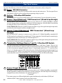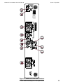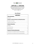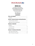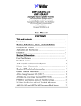
1
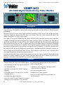
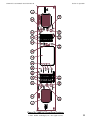
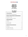
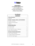
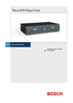
VAMP-AC3
Audio/Video Monitor
6-Channel Digital Audio w/Two AC-3/AES Audio
Inputs and One Loop-Through, One Video input
w/Loop-Through, LCD Monitor, Six 53-Segment
High-Res Level Meters, and Phase Indication
Document P/N 821522 Rev-B
User Manual
CONTENTS
Title and Contents ..................................................... 1
Introduction ................................................................................. 2
Section 1: Features and Specifications ................ 3
General Description and Features ............................................... 4
Applications and Specifications .................................................. 5
Section 2: Operation
................................................ 7
Installation ................................................................................... 9
Front Panel Features .................................................................... 10
Rear Panel Features .................................................................... 14
Section 3: Technical Information ........................... 19
Level Meters ................................................................................ 20
Interconnect Block Diagram ......................................................... 22
© 2002 Wohler Technologies, Inc. ALL rights reserved
1
Important Safety Instructions
1)
Read these instructions.
2)
Keep these instructions.
3)
Heed all warnings.
4)
Follow all instructions.
5)
Do not use this apparatus near water.
6)
Clean only with dry cloth.
7)
Do not block any ventilation openings. Install in accordance with the manufacturer's instructions.
8)
Do not install near any heat source such as radiators, heat registers, stoves, or other apparatus (including
amplifiers) that produce heat.
9)
Do not defeat the safety purpose of the polarized or grounding-type plug. A polarized plug has two blades
with one wider than the other. A grounding type plug has two blades and a third grounding prong. The
wide blade or the third prong are provided for your safety. If the provided plug does not fit into your outlet,
consult an electrician for replacement of the obsolete outlet.
10) Protect the power cord from being walked on or pinched, particularly at plugs convenience receptacles
and the point where they exit from the apparatus.
11) Only use attachments/accessories specified by the manufacturer.
12) Use only with the cart stand, tripod, bracket, or table specified by the manufacturer, or sold with the
apparatus. When a cart is used, use caution when moving the cart/apparatus combination to avoid injury
from tip-over.
13) Unplug this apparatus during lightning storms or when unused for long periods of time.
14) Refer all servicing to qualified service personnel. Servicing is required when the apparatus has been
damaged in any way, such as when power-supply cord or plug is damaged, liquid has been spilled or
objects have fallen into the apparatus, the apparatus has been exposed to rain or moisture, does not
operate normally, or has been dropped.
15) Do not expose this apparatus to rain or moisture.
16) The apparatus shall be connected to a mains socket outlet with a protective earthing connection.
CAUTION!
In products featuring an audio amplifier and speakers, the surface at the side of the
unit, where the audio amplifier heat sink is internally attached, may get very hot after
extended operation. When operating the unit excercise caution when touching this
surface and ensure that external materials which may be adversely affected by heat
are not in contact with it. There is a Hot Surface label (see diagram) attached to the
aforementioned surface of the product.
Introduction
Congratulations on your selection of a Wohler Technologies product. We are confident it represents the best performance and value
available, and we guarantee your satisfaction with it.
If you have questions or comments you may contact us at:
Wohler Technologies, Inc.
31055 Huntwood Avenue
Hayward, CA 94544
Phone: (510) 870-0810
Fax: (510) 870-0811
US Toll-Free: 1-888-596-4537
www.wohler.com
2
[email protected]
© 2007 Wohler Technologies, Inc. ALL rights reserved
VAMP-AC3 User Manual P/N 821522 Rev-B
Sect. 1: General Features and Specifications
Section 1
.
General Features
and Specifications
Description
Features
Applications
Specifications
Dolby is a trademark of Dolby Laboratories, and licensor of technology used in this product. For more information
concerning Dolby Digital and AC-3, please contact Dolby Laboratories directly at [email protected], or Dolby
Laboratories, Inc., 100 Potrero Ave., San Francisco, CA 94103, phone: (415) 558-0200.
© 2002 Wohler Technologies, Inc. ALL rights reserved
3
VAMP-AC3 User Manual P/N 821522 Rev-B
Section 1: General Features and Specifications
VAMP-AC3
AC-3/AES Digital Audio/Analog Video Monitor
VAMP-AC3 Front Panel
Description
The VAMP-AC3 is a powered stereo audio/video monitor designed specifically for simultaneous monitoring of
composite analog video and the six digital audio channels associcated with ATSC/DVB (AC-3/Dolby Digital®)
programming.
The built-in color LCD screen offers simple confidence monitoring of NTSC or PAL video and has front panel
controls for brightness, chroma, tint (NTSC only), and contrast. The video section automatically detects and
indicates the presence of NTSC or PAL signals.
The VAMP-AC3 accepts AC-3 (Dolby Digital®) and/or AES/EBU (PCM) audio input signals providing capabilities
to handle monitoring requirements throughout the facility. Indicator LEDs are provided on the front panel to
identify the selected source as being AC-3 or AES. A toggle switch and LED are also provided to indicate and
allow selection beteween two AC-3 Pro-16 signals, if they are present. High-resolution, wide-range LED bargraph
level meters are provided for all six channels. The 53 bicolor segments, spanning a range of 65 or 90 dB,
simultaneously display signal levels according to both the PPM and VU standards. An adjustable-duration hold of
the peak PPM value may also be displayed as a special option. Bargraph brightness is adjustable via a trim pot.
Both Left/Right and Front/Surround "Phase"/Polarity LED indicators are provided to alert of possible phase
cancellation from mixdown in any likely playback situation.
To isolate possible faults, rotary switches let the operator route any one or pair of inputs to left and right speaker
channels for acoustic monitoring. A toggle switch is provided, which mixes all six channels down to two for
listening to all channels at once and LEDs are provided to indicate this selection.
Features
• 4” Color LCD Video Screen with Brightness,
Chroma, Tint (NTSC Only), and Contrast Controls
•Audio Inputs: Two AC-3/EBU inputs on BNC connec
tors (with one loop-through) and two XLR connectors
(with one loop-through).
• Auto Detection of NTSC/PAL Signals with NTSC/
• Video Inputs: One Composite Video Input On BNC
PAL Indication LED
Connector with Loop-Through
• AES/EBU, or encoded ATSC/MPEG-2 (Dolby
• Self-Powered Speaker System
Digital®)
• Six High-Resolution 53-Segment Tri-Color LED
Bargraph Meters
• Left/Right front “phase" indicators
• Headphone Jack (mutes speakers)
• Line-Level Analog Output of Selected Sources on
XLR Connectors
• Select any channel or pair of channels for isolated
listening, or a stereo mixdown of all 6 channels
4
© 2002 Wohler Technologies, Inc. ALL rights reserved
VAMP-AC3 User Manual P/N 821522 Rev-B
Section 1: General Features and Specifications
Applications
The VAMP-AC3 is intended for use in machine rooms, edit bays, or wherever compact on-the-spot confidence
monitoring of video and six-channel digital audio is required. Thorough magnetic shielding (less than 1 Gauss at
any surface) allows installation of the unit immediately adjacent to video monitors.
Designed, built, and rigorously tested in the U.S., the VAMP-AC3 monitor is backed by a strong two year warranty
and a "satisfaction guaranteed" return policy.
Digital Input Specifications
Input characteristics:
BNC: 75 Ω (ohm) unbalanced
XLR: 110 Ω (ohm) balanced
Minimum input level: 250 mv
Dynamic range:
95 dB
Frequency Response:
10 Hz - 20 kHz +/- 0.5 dB
Analog Output
Distortion:
< 0.005%
Electrical Response:
Amp Power Output:
20Hz -20kH (+/- 1 dB)
170 Hz - 16 kHz (+/- 1 dB)
(-10 dB @ 140 Hz, 20 kHz)
20W Transient / 11W Continuous RMS
each side (4 ohm)
Distortion (electrical): Less than 0.1% at any level below Limit
Threshold
balanced, line-level (20 dbfs=
+4 dBu)
Meter input ‘0’ level: -20 dBfs
Video Specifications
Video Input:
Peak Acoustic Output: 100 dB SPL (@ 2 ft.)
Acoustic Response,
6th Octave:
Conversion data width: 20 bit
Analog outputs:
General Specifications
One Composite Analog - 1V peak
to peak - NTSC/PAL Auto-sensing
Display Resolution: 480H x 230V
Distortion (acoustic): Typically less than 1.5% at frequencies
above 200 Hz; 6% or less at worst case
Hum and Noise:
More than 70 dB below full output
Level Meters:
Six 53-segment high-resolution tri-color
(red/yellow/green) LED bargraphs
Power Requirement:
100/250-VAC, 50/60 Hz Auto Select
Power Consumption: 60W
Screen Type, Size:
TFT 4" Diagonal
Dimensions (HxWxD): 3.5 x 19 x 12 inches (89 x 483 x 298 mm)
Video Controls:
Brightness, Chroma, Tint (NTSC
only), and Contrast
Weight:
17 lbs. Approximately (7.7 kg)
VAMP-AC3 Rear Panel
Units are certified to meet, at time of manufacture, all currently applicable product safety and EMC requirements, such as those of UL
and CE. 0 dbV ref. 0.775V RMS. Features and specifications subject to improvement without notice.
© 2002 Wohler Technologies, Inc. ALL rights reserved
5
VAMP-AC3 User Manual P/N 821522 Rev-B
6
© 2002 Wohler Technologies, Inc. ALL rights reserved
VAMP-AC3 User Manual P/N 821522 Rev-B
Section 2
Operation
Installation
Front Panel Features
Rear Panel Features
© 2002 Wohler Technologies, Inc. ALL rights reserved
7
VAMP-AC3 User Manual P/N 821522 Rev-B
Section 2: Operation
Installation
Figure-2a: VAMP-AC3 Rack Mount Dimensions
8
© 2002 Wohler Technologies, Inc. ALL rights reserved
VAMP-AC3 User Manual P/N 821522 Rev-B
Section 2: Operation
Installation
Unpacking
Unpack the VAMP-AC3 from the shipping container and inspect all articles for shipping damage. If you find any
damage, notify the shipping carrier immediately for claims adjustments.
Compare the shipping box contents to the packing slip. Contact a Wohler sales representative if there are any
unexplained shortages.
Power Requirements
The VAMP-AC3 is equipped with a world standard power supply that is capable of operating on 90-264 VAC
@ 50-60 Hz. Power consumption is 60 watts, maximum. The green Power LED in the front panel center glows
green to indicate the VAMP-AC3 is connected to mains power and an operating voltage is present.
Cooling and Airflow
It is recommended that you allow a 1RU (1.75”/25mm) space above and below the unit for air circulation.
Rack Mounting
The VAMP-AC3 rack mounts in a standard EIA-310-D specification 19”/483mm rack and needs 2RU (3.5”/
88.9mm) of space. (See Figure-2a, facing page, for unit dimensions.) Allow sufficient space at the unit rear for
connector and cable clearance (approximately 4”/102 mm). The VAMP-AC3 weighs approximately 17 pounds
(7.7 kg) and rack mounts from the front panel support rails. Rear support is not required.
LCD Monitor Viewing Position: To obtain the best operator’s viewing angle, mount the VAMP-AC3 as nearly
“straight on” to the operator’s position as possible (0 degrees left/right or up/down). Good image quality is
assured if viewing angles are between +/- 45 degrees from the center axis in the horizontal plane (left/right). In the
vertical axis, good image quality is obtained between 10 degrees looking down and 30 degrees looking up. Due to
the nature of LCD’s, there are certain anomalies, which can cause the displayed video to appear incorrect. If the
viewer is outside the optimal LCD display viewing range, the contrast ratio, brightness, and color saturation will
not be or may not appear to be, a true representation of the displayed video. Additional anomalies such as loss of
resolution, apparent reversed video effect, and frame/field strobe effect with the CCFT backlight may also be
observed. The LCD used in the VAMP-AC3 is optimized for viewing from the 12 o’clock position. That is from
approximately eye height and upwards. Typically, the VAMP-AC3 is mounted at eye height and viewed by
looking straight into the display. Going beyond the specified viewing area can cause anomalies as mentioned
above.
NOTE: In PAL mode operation, the LCD driver discards every seventh line of active video so an entire video
frame fits within the display screen. This is normal with most LCD’s currently on the market.
General Installation Recommendations
Recommended cable type for analog video signals is: Belden 8281, Belden 1694A, or equivalent.
Recommended cable type for digital audio signals is: Belden 1800B or equivalent.
Static Discharge: As with most electronic equipment, static discharges can damage components within the unit.
Take precautions to ensure your installation environment is not subject to static discharges.
© 2002 Wohler Technologies, Inc. ALL rights reserved
9
VAMP-AC3 User Manual P/N 821522 Rev-B
Section 2: Operation
Front Panel Features
Please refer to Figure-2b on the following page to familiarize yourself with the front panel features of the VAMPAC3 unit. The following sections describe these features and are referenced, by number, to Figure-2b.
1
Speakers - Left and Right
The speaker system is comprised of two mid-range speakers (left and right).
2
Selector Disabled Indicators (Left and Right) - Red LEDs
These red LEDs (left and right) glow red to indicate that the left and right Speaker Select switches (Item 3)
are disabled because the ALL/SELECTED toggle switch (Item 5) is set to the “ALL” position.
3
Speaker Select (Left and Right) - 6-Position Rotary Switches
These six position rotary switches allow you to isolate and monitor any one of the six possible channels
independantly through the left and right speakers. Simply choose positions 1 - 6 for either the left or right
speaker and the chosen channel will be monitored from the respective speaker. Note: This function is
disabled if the ALL/SELECTED Channel select switch (Item 5) is in the “ALL” position.
4
Level Meters (Audio) - 53-Segment Bargraph displays
Audio levels for source channels 1-6 are displayed via six high resolution 53-segment LED bargraph
meters (three on the left side of the front panel; three on the right side). Dynamic range for these meters is
65 dB and they are able to display signal levels using both PPM and VU standards. Each meter is labeled
according to the standard Surround Sound nomenclature (left front, right front, center, low frequency effects,
left surround, and right surround).
Contact the factory for additional meter information concerning meter scales and ballistics.
5
ALL/SELECTED Channel Select - 2-Position Toggle Switch
When this 2-position toggle switch in in the “ALL” position, a stereo mixdown of the five full channels is
applied to the speaker amps (the LFE channel is excluded) and the left and right Speaker Select switches
(Item 3) will be disabled (the Selector Disabled Indicator LEDs, Item 2, will also glow red). When in the
“SELECTED” position, channel selection defaults to the left and right Speaker Select switches (the Selector
Disabled Indicator LEDs will be unlit).
6
Pro-16 Select and Indicator - 2-Position Toggle Switch/Amber LED
In the event that you are processing two different Dolby Digital Pro-16 data streams it is possible to select
between the two with this toggle switch (1 or 2). The amber LED above the switch will glow if such
signals are present. In the absence of such data streams, the LED will be unlit and the switch will be
nonfunctional.
7
LCD Monitor Screen - TFT
View input video sources here. Screen image parameters are adjustable by four manual controls (Item 8).
8
LCD Monitor Display Controls - Rotary Pots
Adjust the LCD monitor image with these four controls:
• BRIGHT: Brightness; adjust this knob for desired screen brightness.
• CHROMA: Color Saturation; adjust this knob for desired amount of image color saturation.
• TINT: Tint; adjust this trim pot for desired image color hue (NTCS only).
• CONTRAST: Contrast; adjust this trim pot for desired image scene dark-to-bright contrast.
(Continued)
10
© 2002 Wohler Technologies, Inc. ALL rights reserved
VAMP-AC3 User Manual P/N 821522 Rev-B
Section 2: Operation
Figure-2b: VAMP-AC3 Front Panel Features
© 2002 Wohler Technologies, Inc. ALL rights reserved
11
VAMP-AC3 User Manual P/N 821522 Rev-B
Section 2: Operation
Front Panel Features
(Continued)
9 Power Indicator - Green LED
This LED signals the operating condition of the power supply; it glows green to indicate the VAMP-AC3 is
connected to mains power and an operation voltage is present.
10 Brightness Control (Level Meters) - Recessed Trim Pot
This trim pot simultaneously adjusts the brightness of all the bargraph meters. Turning the trim pot clockwise increases the brightness. You must use a small flathead screwdriver or similar tool to adjust this
control.
11 Input Source Select - 2-Position Toggle Switch
This two position toggle switch allows the operator to choose between two AC-3/AES input sources;
Input Source 1 or Input Source 2. See items C, D, F, and G on pages 14-16 for information on these inputs.
12 Balance Control - Rotary Pot
This pans the volume balance between the left and right speakers (or headphone). If the balance is adjusted
hard right, a slight left/right channel mix is retained so that phase discrepancies may be discerned.
13 Phase Indicator - Green, Green/Red, and Amber LEDs
The phase indication LEDs offer instant verification of phase (polarity) relationships in stereo or mono
sources in the Right-Front and Left-Front channels. There are three LEDs; the two smaller LEDs on either
side show instantaneous phase relationships in the signals, while the center (and larger) LED will indicate
the average phase condition. The left side, or in-phase, LED glows (or blinks) green when signals are in
phase. The right side, or out-of-phase, LED glows (or blinks) amber for out-of-phase signals. The center
LED indicates the average phase condition by glowing green for in-phase conditions, or red for out-ofphase conditions. In general, it is sufficient to regard the center LED (average phase condition) as adequete
for proper phase monitoring. While it is normal for stereo signals to contain some intermittent instantaneous
out-of-phase and in-phase conditions (small LEDs), a steady red glow of the larger center LED almost
always indicates an out-of-phase alarm condition.
14 PAL/NTSC Signal Type Detection - Green LED
This LED will glow green to indicate that the video input signal is of the PAL type. To indicate that the
signal is of the NTSC type the LED will not light up . This signal type detection is automatic.
15 Input Status Indicators - Green LEDs
These two green LEDs indicate which kind of signal is being received at the selected input; either the left
LED for AC-3 (Dolby Digital®) or right LED for AES (or standard PCM; Pulse Code Modulation).
16 Volume Control - Rotary Pot
This controls the loudness of the audio reproduced by the internal speakers or connected headphone.
17 Headphone Jack - 1/4" Phone Connector
Select the headphone audio sources as you would for the internal speakers. When you plug in headphones,
the internal speakers will mute. This jack accepts the standard 1/4” phone type stereo plug.
12
© 2002 Wohler Technologies, Inc. ALL rights reserved
VAMP-AC3 User Manual P/N 821522 Rev-B
Section 2: Operation
Figure-2b: VAMP-AC3 Front Panel Features
© 2002 Wohler Technologies, Inc. ALL rights reserved
13
Section 2: Operation
VAMP-AC3 User Manual P/N 821522 Rev-B
Rear Panel Features
Please refer to Figure-2c on the following page to familiarize yourself with the rear panel features of the VAMPAC3 unit. The following sections describe these features and are referenced, by letter, to Figure-2c.
A Power - IEC-320 Connector
Attach a standard IEC-320 power cord between this connector and mains power. Τhe front panel Power
LED (Item 8) will glow green to indicate that an operating voltage is present.
B Options - 2-Position DIP Switch
This DIP switch is reserved for possible options still to be determined. You may disregard its settings.
C Source 1 Input (Balanced) - XLR Connectors* (IN and Loop-through)
IN: This female 3-pin XLR connector is meant to receive either an AC-3 (Dolby Digital®) or standard
AES (PCM) signal and is configured for a balanced, 110 Ohm connection. Select this input for monitoring
by setting the Source Select switch (Item 11) on the front panel to "1".
LOOP-THROUGH: This male 3-pin XLR connector outputs a copy of the signal entering the input and is
not affected by the front panel controls or headphone mute.
D
Source 1 Input (Unbalanced) - BNC Connectors* (IN and Loopthrough)
IN: This female BNC connector is meant to receive either an AC-3 (Dolby Digital®) or standard AES
(PCM) signal and is configured for an unbalanced, 75 Ohm connection. Select this input for monitoring by
setting the Source Select switch (Item 11) on the front panel to "1".
LOOP-THROUGH: This female BNC connector outputs a copy of the signal entering the input and is not
affected by the front panel controls or headphone mute.
E
Termination Settings (Source 1 and 2) - 2-Position DIP Switch
This DIP switch sets the termination characteristics of the Source 1 and Source 2 inputs. There are two
switches; one for the Source 1 input (S1), and a second switch for the Source 2 input (S2). If input signals
are fed to downstream equipment using the Source 1 loop-through connectors or "T" connectors from
Source 1 or 2, then the respective DIP switch of the source feeding the downstream equipment must be set
to unterminated (UP). If there is no connection to downstream equipment, then the respective DIP switch
section should be set to terminated (DOWN). See the illustration below for DIP switch settings.
F
Source 2 Input (Balanced) - XLR Connector*
This female 3-pin XLR connector is meant to receive either an AC-3 (Dolby Digital®) or standard AES
(PCM) signal and is configured for a balanced, 110 Ohm connection. Select this input for monitoring by
setting the Source Select switch (Item 11) on the front panel to "2".
(Continued)
*You cannot connect two different digital audio signals simultaneously to the balanced (XLR) and
unbalanced (BNC) input connectors in the same input section.
14
© 2002 Wohler Technologies, Inc. ALL rights reserved
VAMP-AC3 User Manual P/N 821522 Rev-B
Section 2: Operation
Figure-2c: VAMP-AC3 Rear Panel Features
© 2002 Wohler Technologies, Inc. ALL rights reserved
15
Section 2: Operation
VAMP-AC3 User Manual P/N 821522 Rev-B
Rear Panel Features
(Continued)
G Source 2 Input (Unbalanced) -BNC Connector*
This female BNC connector is meant to receive either an AC-3 (Dolby Digital®) or standard AES (PCM)
signal and is configured for an unbalanced, 75 Ohm connection. Select this input for monitoring by setting
the Source Select switch (Item 11) on the front panel to "2".
H Selected Output (Analog) - XLR Connectors
These two 3-pin male XLR connectors (left and right) respectively output balanced line-level analog
signals of the monitored audio as selected for the left and right internal speakers or headphone. However,
this output is not affected by the balance (Item 12) and volume (Item 16) controls. See Items 2, 3, 5, 6, and
11 for source selection parameters.
I
Video Input and Loop-Through - Analog - BNC Connectors
ANALOG AUDIO IN: Connect standard composite analog video signals here. PAL and NTSC video
signals are automatically detected and configured for monitoring.
ANALOG LOOP: This connector passes the video input source signal to feed downstream equipment.
See Item J for setting termination.
J Video Input Termination Setting - 2-Position Toggle Switch
When using the Video Loop-through connector (or an external "T" adaptor) to pass video source signals to
feed downstream equipment, you must set the termination toggle switch to Unterminated (DOWN). When
there is no connection to downstream equipment, set this switch to Terminated (UP).
*You cannot connect two different digital audio signals simultaneously to the balanced (XLR) and
unbalanced (BNC) input connectors in the same input section.
16
© 2002 Wohler Technologies, Inc. ALL rights reserved
VAMP-AC3 User Manual P/N 821522 Rev-B
Section 2: Operation
Figure-2c: VAMP-AC3 Rear Panel Features
© 2002 Wohler Technologies, Inc. ALL rights reserved
17
VAMP-AC3 User Manual P/N 821522 Rev-B
18
© 2002 Wohler Technologies, Inc. ALL rights reserved
VAMP-AC3 User Manual P/N 821522 Rev-B
Section 3
Technical Information
Level Meters
Phase Indication
Interconnect Block Diagram
© 2002 Wohler Technologies, Inc. ALL rights reserved
19
VAMP-AC3 User Manual P/N 821522 Rev-B
Section 3: Technical Information
Level Meters
Description
The 53-segment type of tri-color LED bargraph display has a total length of 2.24" (56.8 mm) and uses relatively
small segments. This high resolution segment size is easy to accurately monitor, visually, for distances up to six
feet (1.8 meters). Segment size is 0.158" (4 mm) x 0.04" (1 mm). Segment pitch is .039" (0.99 mm).
Each LED bargraph display section visually indicates the dynamic changes within the audio signal source(s) being
monitored. All bargraph LED segments are of the tri-color type (green, amber, red). Ballistics for these meters
are factory set to display a single floating PPM 'dot' (continuous decay of 20 dB in 1.5 seconds) above a VU bar;
each segment's color being fixed according to its position on the scale. Level gain is factory set at +4 dBu.
Dynamic range for these 53-segment meters is 65 dB.
Scales
Please refer to the figure below for an illustration showing the standard scale for the 53-segment bargraph display
used in the VAMP-AC3 audio/video monitors. Custom variations of this scale are also available on special order.
53-Segment LED Bargraph Specifications
Dynamic range, dB: 65 dB
Midscale resolution: 1 dB
Segment Quantity: 53
0.158" (4 mm) x 0.04" (1 mm)
Segment size:
0.039" (.99 mm)
Segment pitch:
20
© 2002 Wohler Technologies, Inc. ALL rights reserved
VAMP-AC3 User Manual P/N 821522 Rev-B
Section 3: Technical Information
VAMP-AC3 Interconnect Diagram
© 2002 Wohler Technologies, Inc. ALL rights reserved
21
VAMP-AC3 User Manual P/N 821522 Rev-B
Wohler
Technologies, Inc. Inc.
Wohler
Technologies,
713 Grandview Drive
31055 Huntwood Avenue
South San Francisco, CA 94080
Hayward, CA 94544
650 589-5676 Fax: 650 589-1355
Phone: (510) 870-0810 Fax: (510) 870-0811
web: www.wohler.com
US Toll-Free: 1-888-596-4537
e-mail: [email protected]
www.wohler.com [email protected]
52
© 2002 Wohler Technologies, Inc. ALL rights reserved