1
MVI56-MDA4
ControlLogix Platform
MDA Scientific CM4 Platform Master
Module
3/16/2009
USER MANUAL
MVI (Multi Vendor Interface) Modules
WARNING – EXPLOSION HAZARD – DO NOT DISCONNECT EQUIPMENT UNLESS POWER HAS BEEN
SWITCHED OFF OR THE AREA IS KNOWN TO BE NON-HAZARDOUS.
AVERTISSEMENT – RISQUE D'EXPLOSION – AVANT DE DÉCONNECTER L'EQUIPMENT, COUPER LE
COURANT OU S'ASSURER QUE L'EMPLACEMENT EST DÉSIGNÉ NON DANGEREUX.
CL I Div 2 GP A, B, C, D
Temp Code T5
II 3 G
Ex nA nL IIC T4 X
0° C <= Ta <= 60° C
II – Equipment intended for above ground use (not for use in mines).
3 – Category 3 equipment, investigated for normal operation only.
G – Equipment protected against explosive gasses.
Warnings
North America Warnings
A
B
C
Warning - Explosion Hazard - Substitution of components may impair suitability for Class I, Division 2.
Warning - Explosion Hazard - When in Hazardous Locations, turn off power before replacing or rewiring
modules.
Warning - Explosion Hazard - Do not disconnect equipment unless power has been switched off or the area is
known to be nonhazardous.
Suitable for use in Class I, division 2 Groups A, B, C and D Hazardous Locations or Non-Hazardous Locations.
ATEX Warnings and Conditions of Safe Usage:
Power, Input, and Output (I/O) wiring must be in accordance with the authority having jurisdiction
A
B
C
D
Warning - Explosion Hazard - When in hazardous locations, turn off power before replacing or wiring modules.
Warning - Explosion Hazard - Do not disconnect equipment unless power has been switched off or the area is
known to be non-hazardous.
These products are intended to be mounted in an IP54 enclosure. The devices shall provide external means to
prevent the rated voltage being exceeded by transient disturbances of more than 40%. This device must be
used only with ATEX certified backplanes.
DO NOT OPEN WHEN ENERGIZED.
Electrical Ratings
Backplane Current Load: 800 mA @ 5 V DC; 3mA @ 24V DC
Operating Temperature: 0 to 60°C (32 to 140°F)
Storage Temperature: -40 to 85°C (-40 to 185°F)
Shock: 30g Operational; 50g non-operational; Vibration: 5 g from 10 to 150 Hz
Relative Humidity 5% to 95% (non-condensing)
All phase conductor sizes must be at least 1.3 mm(squared) and all earth ground conductors must be at least
4mm(squared).
Markings:
ISA
ISA 12.12.01 Class 1 Div 2
CSA/cUL
C22.2 No. 213-1987
243333
Battery Life Advisory
All modules in the MVI series use a rechargeable Lithium Vanadium Pentoxide battery to backup the 512K SRAM
memory, real-time clock, and CMOS. The battery should last for the life of the module.
The module must be powered for approximately twenty hours before it becomes fully charged. After it is fully charged,
the battery provides backup power for the CMOS setup and configuration data, the real-time clock, and the 512K
SRAM memory for approximately 21 days.
Before you remove a module from its power source, ensure that the battery within the module is fully charged. A fully
charged battery will hold the BIOS settings (after being removed from its power source) for a limited number of days.
When the battery is fully discharged, the module will revert to the default BIOS settings.
Note: The battery is not user replaceable.
Your Feedback Please
We always want you to feel that you made the right decision to use our products. If you have suggestions, comments,
compliments or complaints about the product, documentation or support, please write or call us.
ProSoft Technology
1675 Chester Avenue, Fourth Floor
Bakersfield, CA 93301
+1 (661) 716-5100
+1 (661) 716-5101 (Fax)
http://www.prosoft-technology.com
Copyright © ProSoft Technology, Inc. 2009. All Rights Reserved.
MVI56-MDA4 User Manual
3/16/2009
ProSoft Technology ®, ProLinx ®, inRAx ®, ProTalk® and RadioLinx ® are Registered Trademarks of ProSoft
Technology, Inc.
ProSoft® Product Documentation
In an effort to conserve paper, ProSoft Technology no longer includes printed manuals with our product shipments.
User Manuals, Datasheets, Sample Ladder Files, and Configuration Files are provided on the enclosed CD and are
available at no charge from our web site: http://www.prosoft-technology.com
Printed documentation is available for purchase. Contact ProSoft Technology for pricing and availability.
Asia Pacific: +603.7724.2080
Europe, Middle East, Africa: +33.5.34.36.87.20
Latin America: +1.281.298.9109
North America: +1.661.716.5100
Contents
MVI56-MDA4 ♦ ControlLogix Platform
MDA Scientific CM4 Platform Master Module
Contents
MVI (Multi Vendor Interface) Modules ................................................................................................ 2
Warnings ............................................................................................................................................. 2
Battery Life Advisory ........................................................................................................................... 3
Your Feedback Please........................................................................................................................ 3
ProSoft® Product Documentation....................................................................................................... 3
Guide to the MVI56-MDA4 User Manual
7
1
9
Start Here
1.1
1.2
1.3
1.4
1.5
1.6
1.7
1.8
1.9
2
System Requirements ............................................................................................... 9
Package Contents ................................................................................................... 10
Install ProSoft Configuration Builder Software ........................................................ 10
Setting Jumpers ...................................................................................................... 12
Install the Module in the Rack ................................................................................. 12
Connect your PC to the Processor.......................................................................... 14
Open the Sample Ladder Logic .............................................................................. 14
Download the Sample Program to the Processor................................................... 18
Connect your PC to the Module .............................................................................. 19
Configuring the MVI56-MDA4 Module
2.1
2.2
2.3
2.4
2.5
3
ProSoft Configuration Builder.................................................................................. 21
[Backplane 56]......................................................................................................... 27
[MDA4 Config] ......................................................................................................... 28
[MDA4 Port x] .......................................................................................................... 29
Download the Project to the Module ....................................................................... 31
Ladder Logic
3.1
3.2
4
33
Module Data ............................................................................................................ 33
Adding the Module to an Existing Project ............................................................... 43
Diagnostics and Troubleshooting
4.1
4.2
5
21
47
Reading Status Data from the Module .................................................................... 47
LED Status Indicators.............................................................................................. 55
Reference
5.1
5.2
5.3
5.4
5.5
5.6
ProSoft Technology, Inc.
March 16, 2009
59
Product Specifications............................................................................................. 59
Functional Specifications......................................................................................... 60
Functional Overview................................................................................................ 61
Cable Connections .................................................................................................. 76
MVI56-MDA4 Database Definition .......................................................................... 82
MVI56-MDA4 Status Data Definition....................................................................... 83
Page 5 of 94
Contents
MVI56-MDA4 ♦ ControlLogix Platform
MDA Scientific CM4 Platform Master Module
6
Support, Service & Warranty
85
6.1
6.2
6.3
How to Contact Us: Technical Support................................................................... 85
Return Material Authorization (RMA) Policies and Conditions ............................... 86
LIMITED WARRANTY ............................................................................................ 87
Index
93
Page 6 of 94
ProSoft Technology, Inc.
March 16, 2009
Start Here
MVI56-MDA4 ♦ ControlLogix Platform
MDA Scientific CM4 Platform Master Module
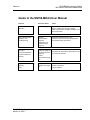
Guide to the MVI56-MDA4 User Manual
Function
Introduction
Section to Read
Details
→
Start Here (page 9)
This Section introduces the customer to the
module. Included are: package contents,
system requirements, hardware installation, and
basic configuration.
→
Verifying
Communication
(page 55)
This section describes how to verify
communications with the network. Diagnostic
and Troubleshooting procedures.
(Must Do)
Verify Communication,
Diagnostic and
Troubleshooting
Diagnostics and
Troubleshooting
(page 47)
Reference
→
Product Specifications
Functional Overview
Product
Specifications (page
59)
Glossary
Support, Service, and
Warranty
Index
ProSoft Technology, Inc.
March 16, 2009
Reference (page 59) These sections contain general references
Functional Overview associated with this product, Specifications, and
the Functional Overview.
(page 61)
→
Support, Service
and Warranty (page
85)
This section contains Support, Service and
Warranty information.
Index of chapters.
Page 7 of 94
MVI56-MDA4 ♦ ControlLogix Platform
MDA Scientific CM4 Platform Master Module
Page 8 of 94
Start Here
ProSoft Technology, Inc.
March 16, 2009
Start Here
1
MVI56-MDA4 ♦ ControlLogix Platform
MDA Scientific CM4 Platform Master Module
Start Here
In This Chapter
System Requirements ............................................................................. 9
Package Contents ................................................................................. 10
Install ProSoft Configuration Builder Software....................................... 10
Setting Jumpers .................................................................................... 12
Install the Module in the Rack ............................................................... 12
Connect your PC to the Processor ........................................................ 14
Open the Sample Ladder Logic............................................................. 14
Download the Sample Program to the Processor.................................. 18
Connect your PC to the Module ............................................................ 19
Installing the MVI56-MDA4 module requires a reasonable working knowledge of
the Rockwell Automation hardware, the MVI56-MDA4 Module and the application
in which they will be used.
Caution: It is important that those responsible for implementation can complete the
application without exposing personnel, or equipment, to unsafe or inappropriate working
conditions. Safety, quality and experience are key factors in a successful installation.
1.1
System Requirements
The MVI56-MDA4 module requires the following minimum hardware and
software components:
Rockwell Automation ControlLogix™ processor, with compatible power
supply and one free slot in the rack, for the MVI56-MDA4 module. The
module requires 800mA of available power.
Rockwell Automation RSLogix 5000 programming software version 2.51 or
higher.
Rockwell Automation RSLinx communication software
Pentium® II 450 MHz minimum. Pentium III 733 MHz (or better)
recommended
Supported operating systems:
o Microsoft Windows XP Professional with Service Pack 1 or 2
o Microsoft Windows 2000 Professional with Service Pack 1, 2, or 3
o Microsoft Windows Server 2003
128 Mbytes of RAM minimum, 256 Mbytes of RAM recommended
ProSoft Technology, Inc.
March 16, 2009
Page 9 of 94
MVI56-MDA4 ♦ ControlLogix Platform
MDA Scientific CM4 Platform Master Module
Start Here
100 Mbytes of free hard disk space (or more based on application
requirements)
256-color VGA graphics adapter, 800 x 600 minimum resolution (True Color
1024 × 768 recommended)
CD-ROM drive
ProSoft Configuration Builder, HyperTerminal or other terminal emulator
program.
Note: You can install the module in a local or remote rack. For remote rack installation, the module
requires EtherNet/IP or ControlNet communication with the processor.
1.2
Package Contents
The following components are included with your MVI56-MDA4 module, and are
all required for installation and configuration.
Important: Before beginning the installation, please verify that all of the following items are
present.
Qty.
Part Name
Part Number
Part Description
1
MVI56-MDA4
Module
MVI56-MDA4
MDA Scientific CM4 Platform Master Module
1
Cable
Cable #15, RS232
Null Modem
For RS232 Connection to the CFG Port
3
Cable
Cable #14, RJ45 to
DB9 Male Adapter
cable
For DB9 Connection to Module's Port
2
Adapter
1454-9F
Two Adapters, DB9 Female to Screw Terminal. For
RS422 or RS485 Connections to Port 1 and 2 of the
Module
1
ProSoft
Solutions CD
Contains sample programs, utilities and
documentation for the MVI56-MDA4 module.
If any of these components are missing, please contact ProSoft Technology
Support for replacement parts.
1.3
Install ProSoft Configuration Builder Software
You must install the ProSoft Configuration Builder (PCB) software in order to
configure the MVI56-MDA4 module. You can always get the newest version of
ProSoft Configuration Builder from the ProSoft Technology web site.
To install ProSoft Configuration Builder from the ProSoft Web Site
1
2
Open your web browser and navigate to http://www.prosofttechnology.com/pcb
Click the Download Here link to download the latest version of ProSoft
Configuration Builder.
Page 10 of 94
ProSoft Technology, Inc.
March 16, 2009
Start Here
MVI56-MDA4 ♦ ControlLogix Platform
MDA Scientific CM4 Platform Master Module
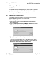
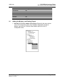
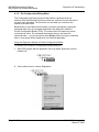
3
Choose "Save" or "Save File" when prompted. The following illustrations
show the file download prompt for two of the most common web browsers.
4
Save the file to your Desktop, so that you can find it easily when you have
finished downloading.
When the download is complete, locate and open the file, and then follow the
instructions on your screen to install the program.
5
If you do not have access to the Internet, you can install ProSoft Configuration
Builder from the ProSoft Solutions CD-ROM, included in the package with your
MVI56-MDA4 module.
To install ProSoft Configuration Builder from the Product CD
1
2
3
4
Insert the ProSoft Solutions Product CD into the CD drive of your PC. Wait for
the startup screen to appear.
On the startup screen, click Product Documentation. This action opens an
explorer window.
Click to open the Utilities folder. This folder contains all of the applications
and files you will need to set up and configure your module.
Double-click the ProSoft Configuration Builder Setup program and follow the
instructions on your screen to install the software on your PC.
Note: Many of the configuration and maintenance procedures use files and other utilities on the
CD-ROM. You may wish to copy the files from the Utilities folder on the CD-ROM to a convenient
location on your hard drive.
ProSoft Technology, Inc.
March 16, 2009
Page 11 of 94
MVI56-MDA4 ♦ ControlLogix Platform
MDA Scientific CM4 Platform Master Module
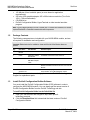
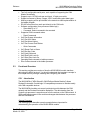
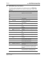
1.4
Start Here
Setting Jumpers
If you use an interface other than RS-232 (default), you must change the jumper
configuration to match the interface. There are three jumpers located at the
bottom of the module.
The following illustration shows the MVI56-MDA4 jumper configuration:
1
2
1.5
Set the PRT 2 (for application port 1) and PRT 3 (for application port 2)
jumpers for RS232, RS422 or RS485 to match the wiring needed for your
application. The default jumper setting for both application ports is RS-232.
The Setup Jumper acts as "write protection" for the module's flash memory.
In "write protected" mode, the Setup pins are not connected, and the
module's firmware cannot be overwritten. Do not jumper the Setup pins
together unless you are directed to do so by ProSoft Technical Support.
Install the Module in the Rack
If you have not already installed and configured your ControlLogix processor and
power supply, please do so before installing the MVI56-MDA4 module. Refer to
your Rockwell Automation product documentation for installation instructions.
Warning: You must follow all safety instructions when installing this or any other electronic
devices. Failure to follow safety procedures could result in damage to hardware or data, or even
serious injury or death to personnel. Refer to the documentation for each device you plan to
connect to verify that suitable safety procedures are in place before installing or servicing the
device.
Page 12 of 94
ProSoft Technology, Inc.
March 16, 2009
Start Here
MVI56-MDA4 ♦ ControlLogix Platform
MDA Scientific CM4 Platform Master Module
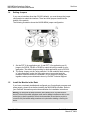
After you have checked the placement of the jumpers, insert MVI56-MDA4 into
the ControlLogix chassis. Use the same technique recommended by Rockwell
Automation to remove and install ControlLogix modules.
Warning: When you insert or remove the module while backplane power is on, an electrical arc
can occur. This could cause an explosion in hazardous location installations. Verify that power is
removed or the area is non-hazardous before proceeding. Repeated electrical arcing causes
excessive wear to contacts on both the module and its mating connector. Worn contacts may
create electrical resistance that can affect module operation.
1
2
Turn power OFF.
Align the module with the top and bottom guides, and slide it into the rack
until the module is firmly against the backplane connector.
3
4
With a firm but steady push, snap the module into place.
Check that the holding clips on the top and bottom of the module are securely
in the locking holes of the rack.
Make a note of the slot location. You will need to identify the slot in which the
module is installed in order for the sample program to work correctly. Slot
numbers are identified on the green circuit board (backplane) of the
ControlLogix rack.
Turn power ON.
5
6
Note: If you insert the module improperly, the system may stop working, or may behave
unpredictably.
Note: If you are installing MVI56-MDA4 with other modules connected to the PCI bus, the
peripheral modules will not have holding clips. Make sure all of the modules are aligned with their
respective slots before you snap them into place.
ProSoft Technology, Inc.
March 16, 2009
Page 13 of 94
MVI56-MDA4 ♦ ControlLogix Platform
MDA Scientific CM4 Platform Master Module
1.6
1.7
Start Here
Connect your PC to the Processor
1
Connect the right-angle connector end of the cable to your controller at the
communications port.
2
Connect the straight connector end of the cable to the serial port on your
computer.
Open the Sample Ladder Logic
The sample program for your MVI56-MDA4 module includes custom tags, data
types and ladder logic for data I/O and status monitoring. For most applications,
you can run the sample ladder program without modification, or, for advanced
applications, you can incorporate the sample program into your existing
application.
The inRAx Solutions CD provides one or more versions of the sample ladder
logic. The version number appended to the file name corresponds with the
firmware version number of your ControlLogix processor. The firmware version
and sample program version must match.
Page 14 of 94
ProSoft Technology, Inc.
March 16, 2009
Start Here
MVI56-MDA4 ♦ ControlLogix Platform
MDA Scientific CM4 Platform Master Module
1.7.1 To Determine the Firmware Version of your Processor
Important: The RSLinx service must be installed and running on your computer in order for
RSLogix to communicate with the processor. Refer to your RSLinx and RSLogix documentation for
help configuring and troubleshooting these applications.
1
2
3
4
Connect an RS-232 serial cable from the COM (serial) port on your PC to the
communication port on the front of the processor.
Start RSLogix 5000 and close any existing project that may be loaded.
Open the Communications menu and choose Go Online. RSLogix will
establish communication with the processor. This may take a few moments.
When RSLogix has established communication with the processor, the
Connected To Go Online dialog box will open.
ProSoft Technology, Inc.
March 16, 2009
Page 15 of 94
MVI56-MDA4 ♦ ControlLogix Platform
MDA Scientific CM4 Platform Master Module
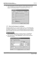
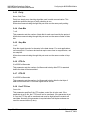
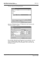
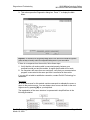
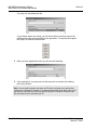
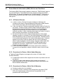
5
Start Here
On the Connected To Go Online dialog box, click the General tab. This tab
shows information about the processor, including the Revision (firmware)
version. In the following illustration, the firmware version is 11.32
1.7.2 Select the Slot Number for the Module
The sample application is for a module installed in Slot 1 in a ControlLogix rack.
The ladder logic uses the slot number to identify the module. If you are installing
the module in a different slot, you must update the ladder logic so that program
tags and variables are correct, and do not conflict with other modules in the rack.
To change the slot number
1
2
In the Controller Organization list, select the module [1] 1756-MODULE
MVI56, and then click the right mouse button to open a shortcut menu.
On the shortcut menu, choose Properties. This action opens the Module
Properties dialog box.
Page 16 of 94
ProSoft Technology, Inc.
March 16, 2009
Start Here
3
MVI56-MDA4 ♦ ControlLogix Platform
MDA Scientific CM4 Platform Master Module
In the Slot: field, use the spinners on the right side of the field to select the
slot number where the module will reside in the rack, and then click OK.
RSLogix will automatically apply the slot number change to all tags, variables
and ladder logic rungs that use the MVI56-MDA4 slot number for computation.
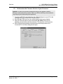
1.7.3 Configuring RSLinx
If RSLogix is unable to establish communication with the processor, follow these steps:
1
2
Open RSLinx.
Open the Communications menu, and choose Configure Drivers.
This action opens the Configure Drivers dialog box.
Note: If the list of configured drivers is blank, you must first choose and configure a driver from the
Available Driver Types list. The recommended driver type to choose for serial communication with
the processor is "RS-232 DF1 Devices".
ProSoft Technology, Inc.
March 16, 2009
Page 17 of 94
MVI56-MDA4 ♦ ControlLogix Platform
MDA Scientific CM4 Platform Master Module
Start Here
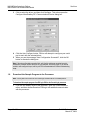
3
Click to select the driver, and then click Configure. This action opens the
Configure Allen-Bradley DF1 Communications Device dialog box.
4
Click the Auto-Configure button. RSLinx will attempt to configure your serial
port to work with the selected driver.
When you see the message "Auto Configuration Successful", click the OK
button to dismiss the dialog box.
5
Note: If the auto-configuration procedure fails, verify that the cables are connected correctly
between the processor and the serial port on your computer, and then try again. If you are still
unable to auto-configure the port, refer to your RSLinx documentation for further troubleshooting
steps.
1.8
Download the Sample Program to the Processor
Note: The key switch on the front of the ControlLogix module must be in the REM position.
To download the sample program from RSLogix 5000 to the ControlLogix processor
1
If you are not already online to the processor, open the Communications
menu, and then choose Download. RSLogix will establish communication
with the processor.
Page 18 of 94
ProSoft Technology, Inc.
March 16, 2009
Start Here
MVI56-MDA4 ♦ ControlLogix Platform
MDA Scientific CM4 Platform Master Module
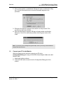
2
When communication is established, RSLogix will open a confirmation dialog
box. Click the Download button to transfer the sample program to the
processor.
3
RSLogix will compile the program and transfer it to the processor. This
process may take a few minutes.
When the download is complete, RSLogix will open another confirmation
dialog box. Click OK to switch the processor from Program mode to Run
mode.
4
Note: If you receive an error message during these steps, refer to your RSLogix documentation to
interpret and correct the error.
1.9
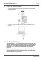
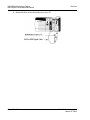
Connect your PC to the Module
With the module securely mounted, connect your PC to the
Configuration/Debug port using an RJ45-DB-9 Serial Adapter Cable and a Null
Modem Cable.
1
2
Attach both cables as shown.
Insert the RJ45 cable connector into the Configuration/Debug port of the
module.
ProSoft Technology, Inc.
March 16, 2009
Page 19 of 94
MVI56-MDA4 ♦ ControlLogix Platform
MDA Scientific CM4 Platform Master Module
3
Start Here
Attach the other end to the serial port on your PC.
Page 20 of 94
ProSoft Technology, Inc.
March 16, 2009
Configuring the MVI56-MDA4 Module
2
MVI56-MDA4 ♦ ControlLogix Platform
MDA Scientific CM4 Platform Master Module
Configuring the MVI56-MDA4 Module
In This Chapter
2.1
ProSoft Configuration Builder ................................................................ 21
[Backplane 56]....................................................................................... 27
[MDA4 Config] ....................................................................................... 28
[MDA4 Port x] ........................................................................................ 29
Download the Project to the Module...................................................... 31
ProSoft Configuration Builder
ProSoft Configuration Builder (PCB) provides a quick and easy way to manage
module configuration files customized to meet your application needs. PCB is not
only a powerful solution for new configuration files, but also allows you to import
information from previously installed (known working) configurations to new
projects.
ProSoft Technology, Inc.
March 16, 2009
Page 21 of 94
MVI56-MDA4 ♦ ControlLogix Platform
MDA Scientific CM4 Platform Master Module
Configuring the MVI56-MDA4 Module
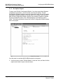
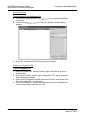
2.1.1 Set Up the Project
To begin, start ProSoft Configuration Builder. If you have used other Windows
configuration tools before, you will find the screen layout familiar. ProSoft
Configuration Builder's window consists of a tree view on the left, an information
pane and a configuration pane on the right side of the window. When you first
start ProSoft Configuration Builder, the tree view consists of folders for Default
Project and Default Location, with a Default Module in the Default Location
folder. The following illustration shows the ProSoft Configuration Builder window
with a new project.
Your first task is to add the MVI56-MDA4 module to the project.
1
Use the mouse to select "Default Module" in the tree view, and then click the
right mouse button to open a shortcut menu.
Page 22 of 94
ProSoft Technology, Inc.
March 16, 2009
Configuring the MVI56-MDA4 Module
MVI56-MDA4 ♦ ControlLogix Platform
MDA Scientific CM4 Platform Master Module
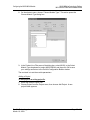
2
On the shortcut menu, choose "Choose Module Type". This action opens the
Choose Module Type dialog box.
3
In the Product Line Filter area of the dialog box, select MVI56. In the Select
Module Type dropdown list, select MVI56-MDA4, and then click OK to save
your settings and return to the ProSoft Configuration Builder window.
The next task is to set the module parameters.
Adding a Project
To add a project to an existing project file:
1
2
Select the Default Project icon.
Choose Project from the Project menu, then choose Add Project. A new
project folder appears.
ProSoft Technology, Inc.
March 16, 2009
Page 23 of 94
MVI56-MDA4 ♦ ControlLogix Platform
MDA Scientific CM4 Platform Master Module
Configuring the MVI56-MDA4 Module
Adding a Module
To add a module to your project:
1
Double-click the Default Module icon to open the Choose Module Type dialog
box.
2
On the Choose Module Type dialog box, select the module type.
Or
1
2
Open the Project menu and choose Location.
On the Location menu, choose Add Module.
To add a module to a different location:
1
Right-click the Location folder and choose Add Module. A new module icon
appears.
Or
1
2
Select the Location icon.
From the Project menu, select Location, then select Add Module.
Page 24 of 94
ProSoft Technology, Inc.
March 16, 2009
Configuring the MVI56-MDA4 Module
MVI56-MDA4 ♦ ControlLogix Platform
MDA Scientific CM4 Platform Master Module
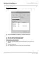
2.1.2 Set Module Parameters
Notice that the contents of the information pane and the configuration pane
changed when you added the MVI56-MDA4 module to the project.
At this time, you may wish to rename the "Default Project" and "Default Location"
folders in the tree view.
To rename an object:
1
2
3
Select the object, and then click the right mouse button to open a shortcut
menu. From the shortcut menu, choose Rename.
Type the name to assign to the object.
Click away from the object to save the new name.
Module Entries
To configure module parameters
1
2
3
4
Click on the plus sign next to the icon
to expand module
information.
Double-click the
icon to open the Edit dialog box.
To edit a parameter, select the parameter in the left pane and make your
changes in the right pane.
Click OK to save your changes.
ProSoft Technology, Inc.
March 16, 2009
Page 25 of 94
MVI56-MDA4 ♦ ControlLogix Platform
MDA Scientific CM4 Platform Master Module
Configuring the MVI56-MDA4 Module
Comment Entries
To add comments to your configuration file:
1
2
3
icon to expand the Module
Click the plus sign to the left of the
Comments.
Double-click the
icon. The Edit - Module Comment dialog
appears.
Enter your comment and click OK to save your changes.
Printing a Configuration File
To print a configuration file:
1
2
3
4
Select the Module icon, and then click the right mouse button to open a
shortcut menu.
On the shortcut menu, choose View Configuration. This action opens the
View Configuration window.
On the View Configuration window, open the File menu, and choose Print.
This action opens the Print dialog box.
On the Print dialog box, choose the printer to use from the dropdown list,
select printing options, and then click OK.
Page 26 of 94
ProSoft Technology, Inc.
March 16, 2009
Configuring the MVI56-MDA4 Module
2.2
MVI56-MDA4 ♦ ControlLogix Platform
MDA Scientific CM4 Platform Master Module
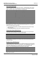
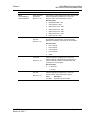
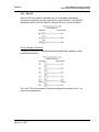
[Backplane 56]
This section designates database addresses for input and output on the module
and on the processor, and identifies the method of failure for the communications
for the module if the processor is not in run mode.
[Backplane 56]
Read Register Start
:
Read Register Count
:
Write Register Start
:
Write Register Count
:
Backplane Fail Count
:
Error/Status Block Pointer
Block Transfer Size
:
:
200 #
#
4000 #
#
0 #
#
200 #
#
10 #
#
6000 #
200 #
Starting register in virtual database to
read from the processor
Number of registers to read from the
processor
Starting register in virtual database to
write to the processor
Number of registers to write to the
processor
Number of consecutive backplane transfer
failures before halting communications
Start of Status Table
Number of words in block (40/200)
2.2.1 Read Register Count
0 to 5000
This parameter specifies the number of registers to be transferred from the
module to the processor. Valid entry for this parameter is 0 to 5000.
2.2.2 Write Register Start
0 to 4999
This parameter specifies the starting register in the module where the data will be
transferred from the processor to the module. Valid range for this parameter is 0
to 4999.
2.2.3 Write Register Count
0 to 5000
This parameter specifies the number of registers to transfer from the processor to
the module. Valid entry for this parameter is 0 to 5000 words.
2.2.4 Backplane Fail Count
0 to 65535
This parameter specifies the number of consecutive backplane transfer failures
that can occur before communications should be halted.
ProSoft Technology, Inc.
March 16, 2009
Page 27 of 94
MVI56-MDA4 ♦ ControlLogix Platform
MDA Scientific CM4 Platform Master Module
Configuring the MVI56-MDA4 Module
2.2.5 Error/Status Block Pointer
-1 to 4955
Starting register location in virtual Modbus database for the error/status table. If a
value of -1 is entered, the error/status data will not be placed in the database. All
other valid values determine the starting location of the data. This data area
includes the module version information and all server error/status data. Refer to
Status Data Definition for more information.
2.2.6 Block Transfer Size
40 or 200
Choose the block transfer size to use for this module. Select 40 for remote rack
installations, or systems where bandwidth is limited. Select 200 for local rack
installations where bandwidth is sufficient to transfer large blocks during each
processor scan cycle.
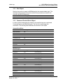
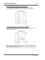
2.3
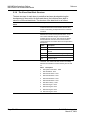
[MDA4 Config]
This section is used to define the MDA4 configuration data.
[MDA4 Config]
Number Of Slaves
Reduced Data Structure
Protocol Version
Polling Delay
:
2
:
No
:
1
: 1000
#
#
#
#
(1 - 10)
(Y/N)
(1/2)
Polling delay in ms
2.3.1 Number of Slaves
0 to 10
This value should represent the total number of slaves which this module will be
polling between the two ports. The module will support up to 10 CM4 units
between the two ports. If not all 10 slots are being used, the operation of the
module can be optimized by accurately selecting the number of slaves.
The optimization comes primarily from reduced number of data block transfers.
If 0 is configured the module assumes that all 10 slots are active.
2.3.2 Reduced Data Structure
Yes or No (default No)
The reduced data structure supports only:
Communication Counter
Communication Status Error
Second
Maintenance Status
Last Concentration Pt.1
Alarm Status Pt.1
Last Concentration Pt.2
Page 28 of 94
ProSoft Technology, Inc.
March 16, 2009
Configuring the MVI56-MDA4 Module
MVI56-MDA4 ♦ ControlLogix Platform
MDA Scientific CM4 Platform Master Module
Alarm Status Pt.2
Last Concentration Pt.3
Alarm Status Pt.3
Last Concentration Pt.4
Alarm Status Pt.4
2.3.3 Protocol Version
1 or 2 (default 1)
This is the protocol version that the CM4 slave unit is configured for. Newer
machines support version 1 and 2, older machines support only version 1.
2.3.4 Polling Delay
0 to 65535 milliseconds (default 1000)
This is the time between polls from the master (MVI56-MDA4) to the slave. The
master polls on this time interval sending the commands that are configured.
2.4
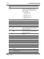
[MDA4 Port x]
This section is used to configure the application port for the MDA4 protocol.
[MDA4 Port 1]
Enable
Baud Rate
:
:
Yes # No=Port Disabled,Yes=Port Enabled
9600 # Baud rate for port (300, 600, 1200, 2400, 4800,
# 9600, 19200, 38400, 57600, 115200)
Parity : None #N=None,O=Odd,E=Even
Data Bits
:
8 # 7 or 8 data bits for messages
Stop Bits
:
1 # 1 or 2 stop bits for messages
RTS On
:
0 # Delay after RTS set before message sent (mSec)
RTS Off
:
0 # Delay after message before RTS dropped (mSec)
Use CTS Line
:
No # Monitor CTS modem line (Y/N)
Response Timeout : 50000 # Maximum number of mSec to receive complete response
# (1-65535ms)
2.4.1 Enabled
Yes or No
This flag specifies if the port on the module will be utilized. If the parameter is set
to No, the port will not be used. If the parameter is set to Yes, the port will be
used supporting the MDA4 protocol.
2.4.2 Baud Rate
This parameter specifies the baud rate to be used on the communication channel
(port). Values from 300 to 115K are supported.
ProSoft Technology, Inc.
March 16, 2009
Page 29 of 94
MVI56-MDA4 ♦ ControlLogix Platform
MDA Scientific CM4 Platform Master Module
Configuring the MVI56-MDA4 Module
2.4.3 Parity
None, Odd, Even
Parity is a simple error checking algorithm used in serial communication. This
parameter specifies the type of parity checking to use.
All devices communicating through this port must use the same parity setting.
2.4.4 Data Bits
7 or 8
This parameter sets the number of data bits for each word used by the protocol.
All devices communicating through this port must use the same number of data
bits.
2.4.5 Stop Bits
1 or 2
Stop bits signal the end of a character in the data stream. For most applications,
use one stop bit. For slower devices that require more time to resynchronize, use
two stop bits.
All devices communicating through this port must use the same number of stop
bits.
2.4.6 RTS On
0 to 65535 milliseconds
This parameter sets the number of milliseconds to delay after RTS is asserted
before the data will be transmitted.
2.4.7 RTS Off
0 to 65535 milliseconds
This parameter sets the number of milliseconds to delay after the last byte of
data is sent before the RTS modem signal will be set low.
2.4.8 Use CTS Line
Yes or No
This parameter specifies if the CTS modem control line is to be used. If the
parameter is set to No, the CTS line will not be monitored. If the parameter is set
to Yes, the CTS line will be monitored and must be high before the module will
send data. Normally, this parameter is required when half-duplex modems are
used for communication (2-wire).
Page 30 of 94
ProSoft Technology, Inc.
March 16, 2009
Configuring the MVI56-MDA4 Module
MVI56-MDA4 ♦ ControlLogix Platform
MDA Scientific CM4 Platform Master Module
2.4.9 Response Timeout
0 to 65535 milliseconds
This parameter represents the message response timeout period in 1 millisecond
increments. This is the time that a port configured as a master will wait before retransmitting a command if no response is received from the addressed slave.
The value is set depending upon the communication network used and the
expected response time of the slowest device on the network.
2.5
Download the Project to the Module
In order for the module to use the settings you configured, you must download
(copy) the updated Project file from your PC to the module.
To Download the Project File
1
2
3
In the tree view in ProSoft Configuration Builder, click once to select the
MVI56-MDA4 module.
Open the Project menu, and then choose Module / Download. The program
will scan your PC for a valid com port (this may take a few seconds). When
PCB has found a valid com port, the following dialog box will open.
Choose the com port to use from the dropdown list, and then click the
Download button.
The module will perform a platform check to read and load its new settings.
When the platform check is complete, the status bar in ProSoft Configuration
Builder will be updated with the message "Module Running".
ProSoft Technology, Inc.
March 16, 2009
Page 31 of 94
MVI56-MDA4 ♦ ControlLogix Platform
MDA Scientific CM4 Platform Master Module
Page 32 of 94
Configuring the MVI56-MDA4 Module
ProSoft Technology, Inc.
March 16, 2009
Ladder Logic
3
MVI56-MDA4 ♦ ControlLogix Platform
MDA Scientific CM4 Platform Master Module
Ladder Logic
In This Chapter
Module Data .......................................................................................... 33
Adding the Module to an Existing Project .............................................. 43
Ladder logic is required for application of the MVI56-MDA4 module. Tasks that
must be handled by the ladder logic are module data transfer, special block
handling and status data receipt. Additionally, a power-up handler may be
needed to handle the initialization of the module's data and to clear any
processor fault conditions.
The sample ladder logic, on the ProSoft Solutions CD-ROM, is extensively
commented, to provide information on the purpose and function of each rung. For
most applications, the sample ladder will work without modification.
3.1
Module Data
This section describes the controller tags that are defined in the example logic to
interface with the module. The user can extend these tags to meet the
specifications required for their application. Additional data is required if the MSG
instructions pass data between the module and the processor.
3.1.1 Module Status Data and Variables (MDA4)
All status and variable data related to the MVI56-MDA4 is stored in a user
defined data type. An instance of the data type is required before the module can
be used. This is done by declaring a variable of the data type in the Controller
Tags Edit Tags dialog box. The following table describes the structure of this
object.
Name
Data Type
Backplane
MDA4Backplane
Statistics
MDA4InStat
Data
MDA4Data
ActiveSlaves
MDA4PollingList
CmndCtrlBlock
CommandControlBlock[10]
Result
INT[4]
SubScript
INT
Description
This object contains objects that define variables to be used with the module and
status data related to the module. Each of these object types is discussed in the
following topics of the document.
ProSoft Technology, Inc.
March 16, 2009
Page 33 of 94
MVI56-MDA4 ♦ ControlLogix Platform
MDA Scientific CM4 Platform Master Module
Ladder Logic
Status Object (MDA4InStat)
This object stores the status data of the module. The MDA4InStat object shown
below is updated each time a read block is received by the processor. Use this
data to monitor the state of the module at a "real-time rate".
Name
PassCnt
Product
Code
Rev
OP
Run
PrtErrs
BlkErrs
Port1CurErr
Port1LErr
Port2CurErr
Port2LErr
Data Type
INT
INT[4]
INT[2]
INT[2]
INT[2]
INT[2]
MDA4PortErrors[2]
MDA4BlkStat
INT
INT
INT
INT
Description
Program cycle counter
Product Name
Revision Level Number
Operating Level Number
Run Number
Port error statistics
Block transfer statistics
Current error/index for Port 1
Last error/index for Port 1
Current error/index for Port 2
Last error/index for Port 2
Within the MDA4InStat objects are objects containing the status information for
each application port. Refer to Status Data Definition (page 83) for a complete
listing of the data stored in this object.
For the Reduced Data Block, this data is acquired from the module using a
MSG instruction.
For the Large Data Block, this data is acquired with each block.
Channel Status Object (MDA4PortErrors)
The MDA4PortErrors object holds the status data related to a single CM4 port.
The following table describes the structure of this object.
Name
Requests
Responses
ErrSent
ErrRec
Data Type
INT
INT
INT
INT
Description
Total number of requests for port
Total number of responses for port
Total number of errors sent
Total number of errors received
This information is passed to the controller from the module with each normal
read block image.
Backplane Object (MDA4Backplane)
The MDA4Backplane object stores all the variables required for the data transfer
operation between the module and the controller. The LastRead data member is
used as the handshaking byte to indicate the arrival of new data from the
module. The following table describes the structure of the object.
Name
LastRead
LastWrite
BlockIndex
Data Type
INT
INT
INT
Description
Index of last read block
Index of last write block
Computed block offset for data table
The other members of the object are utilized in the ladder logic to assist in the
data transfer operation.
Page 34 of 94
ProSoft Technology, Inc.
March 16, 2009
Ladder Logic
MVI56-MDA4 ♦ ControlLogix Platform
MDA Scientific CM4 Platform Master Module
3.1.2 Data Object
Data for the module is stored in MDAData tag for the example ladder logic. The
read data (data transferred from the module to the processor) is stored in the
controller tag MDA4.Response[ ].
Name
Data Type
Response
Response[10]
Description
3.1.3 Command Control Block Object
In order to send commands to the module, two controller tags are constructed,
CommandControl and MDA4PollingList. The bits in the array trigger the
commands. The following table describes the structure of this object.
CommandControlBlock
Name
Data Type
ReadCmdEnable
INT
WriteCmdEnable
INT
AlarmFaultResetSel
INT
LockKbdCmd
INT
LockKbdKeycode
INT
Reserved1
INT
Reserved2
INT
Reserved3
INT
Reserved4
INT
Reserved5
INT
Description
MDA4PollingList
Name
Data Type
Description
PortSelect1
INT
Port select (0/1)
SlaveID1
INT
Slave ID (1/255)
PortSelect2
INT
Port select (0/1)
SlaveID2
INT
Slave ID (1/255)
PortSelect3
INT
Port select (0/1)
SlaveID3
INT
Slave ID (1/255)
PortSelect4
INT
Port select (0/1)
SlaveID4
INT
Slave ID (1/255)
PortSelect5
INT
Port select (0/1)
SlaveID5
INT
Slave ID (1/255)
PortSelect6
INT
Port select (0/1)
SlaveID6
INT
Slave ID (1/255)
PortSelect7
INT
Port select (0/1)
SlaveID7
INT
Slave ID (1/255)
PortSelect8
INT
Port select (0/1)
ProSoft Technology, Inc.
March 16, 2009
Page 35 of 94
MVI56-MDA4 ♦ ControlLogix Platform
MDA Scientific CM4 Platform Master Module
Ladder Logic
Name
Data Type
Description
SlaveID8
INT
Slave ID (1/255)
PortSelect9
INT
Port select (0/1)
SlaveID9
INT
Slave ID (1/255)
PortSelect10
INT
Port select (0/1)
SlaveID10
INT
Slave ID (1/255)
3.1.4 User Data Objects
These objects hold data to be transferred between the processor and the MVI56MDA4 module. The user data is the read data transferred between the processor
and the module as "pages" of data up to 200 words long.
Name
Data Type
Description
CommCounter
INT
Increments each time communication with
the slave occurs
CommStatusError
INT
Communication Status
ReadComDone
INT
WriteCmdDone
INT
AlarmResetStatus
INT
LockKbdStatus
INT
EndPntLockResults
INT
StartPntLockResults
INT
Spare1
INT
Spare2
INT
Month
INT
Day
INT
Year
INT
Hour
INT
Minute
INT
Second
INT
NumberOfAlarms
INT
Spare3
INT
Spare4
INT
Spare5
INT
SerialNumber
INT
SoftwareRev
INT
VIP
INT
PromCsumMsb
INT
PromCsumLsb
INT
StatusReadVerified
INT
GeneralStatus
INT
FlashMemRemain
INT
ChemcassetteWinRemain
INT
Page 36 of 94
ProSoft Technology, Inc.
March 16, 2009
Ladder Logic
MVI56-MDA4 ♦ ControlLogix Platform
MDA Scientific CM4 Platform Master Module
Name
Data Type
ChemcassetteDaysRemain
INT
InternalFilterdays
INT
ExternalFilterDays
INT
FlowRatePt1
INT
FlowRatePt2
INT
FlowRatePt3
INT
FlowRatePt4
INT
StatusOpticsCalMaint
INT
Spare6
INT
Spare7
INT
Spare8
INT
MDAGasAbrv1Pt1
INT
MDAGasAbrv2Pt1
INT
MDAGasAbrv3Pt1
INT
FormatCodePt1
INT
FlowRateCurrentPt1
INT
TWAStartDatePt1
INT
TWAStartTimePt1
INT
TWAEndDatePt1
INT
TWAEndTimePt1
INT
TWAConcPt1
INT
LastConcPt1
INT
AlarmStatusPt1
INT
PointStatusPt1
INT
PointCfgStatusPt1
INT
AlarmLevel1Pt1
INT
AlarmLevel2Pt1
INT
Spare1Pt1
INT
Spare2Pt1
INT
Spare3Pt1
INT
Spare4Pt1
INT
MDAGasAbrv1Pt2
INT
MDAGasAbrv2Pt2
INT
MDAGasAbrv3Pt2
INT
FormatCodePt2
INT
FlowRateCurrentPt2
INT
TWAStartDatePt2
INT
TWAStartTimePt2
INT
TWAEndDatePt2
INT
TWAEndTimePt2
INT
TWAConcPt2
INT
ProSoft Technology, Inc.
March 16, 2009
Description
Page 37 of 94
MVI56-MDA4 ♦ ControlLogix Platform
MDA Scientific CM4 Platform Master Module
Name
Data Type
LastConcPt2
INT
AlarmStatusPt2
INT
PointStatusPt2
INT
PointCfgStatusPt2
INT
AlarmLevel1Pt2
INT
AlarmLevel2Pt2
INT
Spare1Pt2
INT
Spare2Pt2
INT
Spare3Pt2
INT
Spare4Pt2
INT
MDAGasAbrv1Pt3
INT
MDAGasAbrv2Pt3
INT
MDAGasAbrv3Pt3
INT
FormatCodePt3
INT
FlowRateCurrentPt3
INT
TWAStartDatePt3
INT
TWAStartTimePt3
INT
TWAEndDatePt3
INT
TWAEndTimePt3
INT
TWAConcPt3
INT
LastConcPt3
INT
AlarmStatusPt3
INT
PointStatusPt3
INT
PointCfgStatusPt3
INT
AlarmLevel1Pt3
INT
AlarmLevel2Pt3
INT
Spare1Pt3
INT
Spare2Pt3
INT
Spare3Pt3
INT
Spare4Pt3
INT
MDAGasAbrv1Pt4
INT
MDAGasAbrv2Pt4
INT
MDAGasAbrv3Pt4
INT
FormatCodePt4
INT
FlowRateCurrentPt4
INT
TWAStartDatePt4
INT
TWAStartTimePt4
INT
TWAEndDatePt4
INT
TWAEndTimePt4
INT
TWAConcPt4
INT
LastConcPt4
INT
Page 38 of 94
Ladder Logic
Description
ProSoft Technology, Inc.
March 16, 2009
Ladder Logic
MVI56-MDA4 ♦ ControlLogix Platform
MDA Scientific CM4 Platform Master Module
Name
Data Type
AlarmStatusPt4
INT
PointStatusPt4
INT
PointCfgStatusPt4
INT
AlarmLevel1Pt4
INT
AlarmLevel2Pt4
INT
Spare1Pt4
INT
Spare2Pt4
INT
Spare3Pt4
INT
Spare4Pt4
INT
Al1DateStamp
INT
Al1TimeStamp
INT
Al1GasAbrv1
INT
AI1GasAbrv2
INT
AI1GasAbrv3
INT
Al1PtNumber
INT
Al1Formatcode
INT
Al1Concentration
INT
Al1AlarmLevel
INT
Al1Spare
INT
Al2DateStamp
INT
Al2TimeStamp
INT
Al2GasAbrv1
INT
Al2GasAbrv2
INT
Al2GasAbrv3
INT
Al2PtNumber
INT
Al2Formatcode
INT
Al2Concentration
INT
Al2AlarmLevel
INT
Al2Spare
INT
Al3DateStamp
INT
Al3TimeStamp
INT
Al3GasAbrv1
INT
Al3GasAbrv2
INT
Al3GasAbrv3
INT
Al3PtNumber
INT
Al3Formatcode
INT
Al3Concentration
INT
Al3AlarmLevel
INT
Al3Spare
INT
Al4DateStamp
INT
Al4TimeStamp
INT
ProSoft Technology, Inc.
March 16, 2009
Description
Page 39 of 94
MVI56-MDA4 ♦ ControlLogix Platform
MDA Scientific CM4 Platform Master Module
Name
Data Type
Al4GasAbrv1
INT
Al4GasAbrv2
INT
Al4GasAbrv3
INT
Al4PtNumber
INT
Al4Formatcode
INT
Al4Concentration
INT
Al4AlarmLevel
INT
Al4Spare
INT
Al5DateStamp
INT
Al5TimeStamp
INT
Al5GasAbrv1
INT
Al5GasAbrv2
INT
Al5GasAbrv3
INT
Al5PtNumber
INT
Al5Formatcode
INT
Al5Concentration
INT
Al5AlarmLevel
INT
Al5Spare
INT
Al6DateStamp
INT
Al6TimeStamp
INT
Al6GasAbrv1
INT
Al6GasAbrv2
INT
Al6GasAbrv3
INT
Al6PtNumber
INT
Al6Formatcode
INT
Al6Concentration
INT
Al6AlarmLevel
INT
Al6Spare
INT
Al7DateStamp
INT
Al7TimeStamp
INT
Al7GasAbrv1
INT
Al7GasAbrv2
INT
Al7GasAbrv3
INT
Al7PtNumber
INT
Al7Formatcode
INT
Al7Concentration
INT
Al7AlarmLevel
INT
Al7Spare
INT
Al8DateStamp
INT
Al8TimeStamp
INT
Al8GasAbrv1
INT
Page 40 of 94
Ladder Logic
Description
ProSoft Technology, Inc.
March 16, 2009
Ladder Logic
MVI56-MDA4 ♦ ControlLogix Platform
MDA Scientific CM4 Platform Master Module
Name
Data Type
Al8GasAbrv2
INT
Al8GasAbrv3
INT
Al8PtNumber
INT
Al8Formatcode
INT
Al8Concentration
INT
Al8AlarmLevel
INT
Al8Spare
INT
Al9DateStamp
INT
Al9TimeStamp
INT
Al9GasAbrv1
INT
Al9GasAbrv2
INT
Al9GasAbrv3
INT
Al9PtNumber
INT
Al9Formatcode
INT
Al9Concentration
INT
Al9AlarmLevel
INT
Al9Spare
INT
Al10DateStamp
INT
Al10TimeStamp
INT
Al10GasAbrv1
INT
Al10GasAbrv2
INT
Al10GasAbrv3
INT
Al10PtNumber
INT
Al10Formatcode
INT
Al10Concentration
INT
Al10AlarmLevel
INT
Al10Spare
INT
Al11DateStamp
INT
Al11TimeStamp
INT
Al11GasAbrv1
INT
Al11GasAbrv2
INT
Al11GasAbrv3
INT
Al11PtNumber
INT
Al11Formatcode
INT
Al11Concentration
INT
Al11AlarmLevel
INT
Al11Spare
INT
Al12DateStamp
INT
Al12TimeStamp
INT
Al12GasAbrv1
INT
Al12GasAbrv2
INT
ProSoft Technology, Inc.
March 16, 2009
Description
Page 41 of 94
MVI56-MDA4 ♦ ControlLogix Platform
MDA Scientific CM4 Platform Master Module
Name
Data Type
Al12GasAbrv3
INT
Al12PtNumber
INT
Al12Formatcode
INT
Al12Concentration
INT
Al12AlarmLevel
INT
Al12Spare
INT
Al13DateStamp
INT
Al13TimeStamp
INT
Al13GasAbrv1
INT
Al13GasAbrv2
INT
Al13GasAbrv3
INT
Al13PtNumber
INT
Al13Formatcode
INT
Al13Concentration
INT
Al13AlarmLevel
INT
Al13Spare
INT
Al14DateStamp
INT
Al14TimeStamp
INT
Al14GasAbrv1
INT
Al14GasAbrv2
INT
Al14GasAbrv3
INT
Al14PtNumber
INT
Al14Formatcode
INT
Al14Concentration
INT
Al14AlarmLevel
INT
Al14Spare
INT
Al15DateStamp
INT
Al15TimeStamp
INT
Al15GasAbrv1
INT
Al15GasAbrv2
INT
Al15GasAbrv3
INT
Al15PtNumber
INT
Al15Formatcode
INT
Al15Concentration
INT
Al15AlarmLevel
INT
Al15Spare
INT
Al16DateStamp
INT
Al16TimeStamp
INT
Al16GasAbrv1
INT
Al16GasAbrv2
INT
Al16GasAbrv3
INT
Page 42 of 94
Ladder Logic
Description
ProSoft Technology, Inc.
March 16, 2009
Ladder Logic
3.2
MVI56-MDA4 ♦ ControlLogix Platform
MDA Scientific CM4 Platform Master Module
Name
Data Type
Al16PtNumber
INT
Al16Formatcode
INT
Al16Concentration
INT
Al16AlarmLevel
INT
Al16Spare
INT
Reserved
INT[20]
Description
Adding the Module to an Existing Project
1
Add the MVI56-MDA4 module to the project. Right-click the mouse button
on the I/O Configuration option in the Controller Organization window to
display a pop-up menu. Select the New Module option from the I/O
Configuration menu.
ProSoft Technology, Inc.
March 16, 2009
Page 43 of 94
MVI56-MDA4 ♦ ControlLogix Platform
MDA Scientific CM4 Platform Master Module
Ladder Logic
This action opens the following dialog box:
Select the 1756-Module (Generic 1756 Module) from the list and click OK.
The following dialog box appears.
Enter the Name, Description and Slot options for your application. You must
select the Comm Format as Data - INT in the dialog box, otherwise the
module will not communicate over the backplane of the ControlLogix rack.
Click OK to continue.
Page 44 of 94
ProSoft Technology, Inc.
March 16, 2009
Ladder Logic
MVI56-MDA4 ♦ ControlLogix Platform
MDA Scientific CM4 Platform Master Module
2
Edit the Module Properties. Select the Requested Packet Interval value for
scanning the I/O on the module. This value represents the minimum
frequency that the module will handle scheduled events. This value should
not be set to less than 1 millisecond. The default value is 5 milliseconds.
Values between 1 and 10 milliseconds should work with most applications.
3
Save the module. Click OK to dismiss the dialog box. The Controller
Organization window now displays the module's presence. The following
illustration shows the Controller Organization window:
4
5
6
7
Copy the Controller Tags from the sample program.
Copy the User Defined Data Types from the sample program.
Copy the Ladder Rungs from the sample program.
Save and Download (page 18) the new application to the controller and place
the processor in run mode.
ProSoft Technology, Inc.
March 16, 2009
Page 45 of 94
MVI56-MDA4 ♦ ControlLogix Platform
MDA Scientific CM4 Platform Master Module
Page 46 of 94
Ladder Logic
ProSoft Technology, Inc.
March 16, 2009
Diagnostics and Troubleshooting
4
MVI56-MDA4 ♦ ControlLogix Platform
MDA Scientific CM4 Platform Master Module
Diagnostics and Troubleshooting
In This Chapter
Reading Status Data from the Module .................................................. 47
LED Status Indicators............................................................................ 55
The module provides information on diagnostics and troubleshooting in the
following forms:
4.1
Status data values are transferred from the module to the processor.
Data contained in the module can be viewed through the
Configuration/Debug port attached to a terminal emulator.
LED status indicators on the front of the module provide information on the
module's status.
Reading Status Data from the Module
The MVI56-MDA4 module returns a 29-word Status Data Block that may be used
to determine the module's operating status. This data is located in the module's
database in registers 5000 through 5028.
This data is transferred to the ControlLogix processor continuously with each
read block.
The Configuration/Debug port provides the following functionality:
Full view of the module's configuration data
View of the module's status data
Complete display of the module's internal database (registers 0 to 6999)
Version Information
Control over the module (warm boot, cold boot, transfer configuration)
4.1.1 Required Hardware
You can connect directly from your computer's serial port to the serial port on the
module to view configuration information, perform maintenance, and send
(upload) or receive (download) configuration files.
ProSoft Technology recommends the following minimum hardware to connect
your computer to the module:
80486 based processor (Pentium preferred)
1 megabyte of memory
At least one UART hardware-based serial communications port available.
USB-based virtual UART systems (USB to serial port adapters) often do not
function reliably, especially during binary file transfers, such as when
uploading/downloading configuration files or module firmware upgrades.
A null modem serial cable.
ProSoft Technology, Inc.
Page 47 of 94
March 16, 2009
MVI56-MDA4 ♦ ControlLogix Platform
MDA Scientific CM4 Platform Master Module
Diagnostics and Troubleshooting
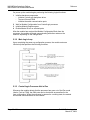
4.1.2 The Configuration/Debug Menu
The Configuration and Debug menu for this module is arranged as a tree
structure, with the Main Menu at the top of the tree, and one or more sub-menus
for each menu command. The first menu you see when you connect to the
module is the Main menu.
Because this is a text-based menu system, you enter commands by typing the
command letter from your computer keyboard in the diagnostic window in
ProSoft Configuration Builder (PCB). The module does not respond to mouse
movements or clicks. The command executes as soon as you press the
command letter — you do not need to press [Enter]. When you type a command
letter, a new screen will be displayed in your terminal application.
Using the Diagnostic Window in ProSoft Configuration Builder
To connect to the module's Configuration/Debug serial port:
1
Start PCB program with the application file to be tested. Right click over the
module icon.
2
On the shortcut menu, choose Diagnostics.
Page 48 of 94
ProSoft Technology, Inc.
March 16, 2009
Diagnostics and Troubleshooting
3
MVI56-MDA4 ♦ ControlLogix Platform
MDA Scientific CM4 Platform Master Module
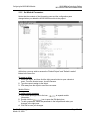
This action opens the Diagnostics dialog box. Press "?" to display the Main
Menu.
Important: The illustrations of configuration/debug menus in this section are intended as a general
guide, and may not exactly match the configuration/debug menus in your own module.
If there is no response from the module, follow these steps:
1
2
Verify that the null modem cable is connected properly between your
computer's serial port and the module. A regular serial cable will not work.
On computers with more than one serial port, verify that your communication
program is connected to the same port that is connected to the module.
If you are still not able to establish a connection, contact ProSoft Technology for
assistance.
Navigation
All of the sub-menus for this module contain commands to redisplay the menu or
return to the previous menu. You can always return from a sub-menu to the next
higher menu by pressing [M] on your keyboard.
The organization of the menu structure is represented in simplified form in the
following illustration:
ProSoft Technology, Inc.
March 16, 2009
Page 49 of 94
MVI56-MDA4 ♦ ControlLogix Platform
MDA Scientific CM4 Platform Master Module
Diagnostics and Troubleshooting
The remainder of this section shows you the menus available for this module,
and briefly discusses the commands available to you.
Keystrokes
The keyboard commands on these menus are almost always non-case sensitive.
You can enter most commands in lower case or capital letters.
The menus use a few special characters ([?], [-], [+], [@]) that must be entered
exactly as shown. Some of these characters will require you to use the [Shift],
[Ctrl] or [Alt] keys to enter them correctly. For example, on US English
keyboards, enter the [?] command as [Shift][/].
Also, take care to distinguish capital letter [I] from lower case letter [l] (L) and
number [1]; likewise for capital letter [O] and number [0]. Although these
characters look nearly the same on the screen, they perform different actions on
the module.
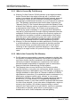
4.1.3 Main Menu
When you first connect to the module from your computer, your terminal screen
will be blank. To activate the main menu, press the [?] key on your computer's
keyboard. If the module is connected properly, the following menu will appear on
your terminal screen:
Caution: Some of the commands available to you from this menu are designed for advanced
debugging and system testing only, and can cause the module to stop communicating with the
processor or with other devices, resulting in potential data loss or other failures. Only use these
commands if you are specifically directed to do so by ProSoft Technology Technical Support staff.
Some of these command keys are not listed on the menu, but are active nevertheless. Please be
careful when pressing keys so that you do not accidentally execute an unwanted command.
Redisplaying the Menu
Press [?] to display the current menu. Use this command when you are looking
at a screen of data, and want to view the menu choices available to you.
Page 50 of 94
ProSoft Technology, Inc.
March 16, 2009
Diagnostics and Troubleshooting
MVI56-MDA4 ♦ ControlLogix Platform
MDA Scientific CM4 Platform Master Module
Viewing Version Information
Press [V] to view Version information for the module.
Use this command to view the current version of the software for the module, as
well as other important values. You may be asked to provide this information
when calling for technical support on the product.
Values at the bottom of the display are important in determining module
operation. The Program Scan Counter value is incremented each time a
module's program cycle is complete.
Tip: Repeat this command at one-second intervals to determine the frequency of program
execution.
Opening the Database Menu
Press [D] to open the Database View menu. Use this menu command to view the
current contents of the module's database.
Clearing Diagnostic Data
Press [C] to clear diagnostic data from the module's memory.
Viewing Backplane Diagnostic Information
Press [B] from the Configuration/Debug Menu to view the Backplane Diagnostic
Information screen.
Use this command to display the configuration and statistics of the backplane
data transfer operations between the module and the processor. The information
on this screen can help determine if there are communication problems between
the processor and the module.
Tip: Repeat this command at one-second intervals to determine the number of blocks transferred
each second.
Opening the Protocol Serial MDA4 Menu
Press [0] (port 1) or [1] (port 2) to open the Protocol Serial menu for the MVI56MDA4 module.
The Protocol Serial Menu (page 54) section has more information about the
commands on this menu.
Receiving the Configuration File
Press [R] to download (receive) the current configuration file from the module.
For more information on receiving and sending configuration files, please see
Uploading and Downloading the Configuration File.
Sending the Configuration file
Press [R] to upload (send) an updated configuration file to the module.
ProSoft Technology, Inc.
March 16, 2009
Page 51 of 94
MVI56-MDA4 ♦ ControlLogix Platform
MDA Scientific CM4 Platform Master Module
Diagnostics and Troubleshooting
Warm Booting the Module
Caution: Some of the commands available to you from this menu are designed for advanced
debugging and system testing only, and can cause the module to stop communicating with the
processor or with other devices, resulting in potential data loss or other failures. Only use these
commands if you are specifically directed to do so by ProSoft Technology Technical Support staff.
Some of these command keys are not listed on the menu, but are active nevertheless. Please be
careful when pressing keys so that you do not accidentally execute an unwanted command.
Press [W] from the Main Menu to warm boot (restart) the module. This command
will cause the program to exit and reload, refreshing configuration parameters
that must be set on program initialization. Only use this command if you must
force the module to re-boot.
Exiting the Program
Caution: Some of the commands available to you from this menu are designed for advanced
debugging and system testing only, and can cause the module to stop communicating with the
processor or with other devices, resulting in potential data loss or other failures. Only use these
commands if you are specifically directed to do so by ProSoft Technology Technical Support staff.
Some of these command keys are not listed on the menu, but are active nevertheless. Please be
careful when pressing keys so that you do not accidentally execute an unwanted command.
Press [Esc] to restart the module and force all drivers to be loaded. The module
will use the configuration stored in the module's Flash ROM to configure the
module.
Page 52 of 94
ProSoft Technology, Inc.
March 16, 2009
Diagnostics and Troubleshooting
MVI56-MDA4 ♦ ControlLogix Platform
MDA Scientific CM4 Platform Master Module
4.1.4 Database View Menu
Press [D] from the Main Menu to open the Database View menu. Use this menu
command to view the current contents of the module's database. Press [?] to
view a list of commands available on this menu.
Viewing Database Pages 0 to 3000
The database is divided into pages that correspond with a specific number of
registers. The total number of database pages and registers depends on the
memory capacity and configuration of the module.
Use the keyboard commands [0] through [3] to display database contents
starting from 0 (zero), 1000, 2000 and 3000 respectively.
Moving Back Through 5 Pages of Registers
Press [-] from the Database View menu to skip back to the previous 500
registers of data.
Viewing the Previous 100 Registers of Data
Press [P] from the Database View menu to display the previous 100 registers of
data.
Skipping 500 Registers of Data
Hold down [Shift] and press [=] to skip forward to the next 500 registers of data.
ProSoft Technology, Inc.
March 16, 2009
Page 53 of 94
MVI56-MDA4 ♦ ControlLogix Platform
MDA Scientific CM4 Platform Master Module
Diagnostics and Troubleshooting
Viewing the Next 100 Registers of Data
Press [N] from the Database View menu to select and display the next 100
registers of data.
Viewing Data in Decimal Format
Press [D] to display the data on the current page in decimal format.
Viewing Data in Hexadecimal Format
Press [H] to display the data on the current page in hexadecimal format.
Viewing Data in Floating Point Format
Press [F] from the Database View menu. Use this command to display the data
on the current page in floating point format. The program assumes that the
values are aligned on even register boundaries. If floating-point values are not
aligned as such, they are not displayed properly.
Viewing Data in ASCII (Text) Format
Press [A] to display the data on the current page in ASCII format. This is useful
for regions of the database that contain ASCII data.
Returning to the Main Menu
Press [M] to return to the Main Menu.
4.1.5 Protocol Serial Menu
Use this menu to display the communication status and statistics of port 1 [0] and
port 2 [1], respectively.
Redisplaying the Menu
Press [?] to display the current menu. Use this command when you are looking
at a screen of data, and want to view the menu choices available to you.
Page 54 of 94
ProSoft Technology, Inc.
March 16, 2009
Diagnostics and Troubleshooting
MVI56-MDA4 ♦ ControlLogix Platform
MDA Scientific CM4 Platform Master Module
Viewing Version Information
Press [V] to view Version information for the module.
Use this command to view the current version of the software for the module, as
well as other important values. You may be asked to provide this information
when calling for technical support on the product.
Values at the bottom of the display are important in determining module
operation. The Program Scan Counter value is incremented each time a
module's program cycle is complete.
Tip: Repeat this command at one-second intervals to determine the frequency of program
execution.
Returning to the Main Menu
Press [M] to return to the Main Menu.
Viewing Configuration Information
Press [C] to view configuration information for the selected port, protocol, driver
or device.
Viewing Serial Port status
Press [V] to view serial port status.
Viewing Program Status
Press [E] from the Protocol Serial Menu to view the Program Status screen.
4.2
LED Status Indicators
The LEDs will indicate the module's operating status as follows:
Module
Color
Status
Indication
CFG
Green
On
Data is being transferred between the module and a remote
terminal using the Configuration/Debug port.
Off
No data is being transferred on the Configuration/Debug port.
On
Data being transferred between master and port 1.
Off
No data
On
Data being transferred between master and port 2.
Off
No data
Off
The MVI56-MDA4 module program has recognized a
communication error.
On
The MVI56-MDA4 is working normally.
On
The LED is on when the module is performing a write
operation on the backplane.
Off
The LED is off when the module is performing a read
operation on the backplane. Under normal operation, the LED
should blink rapidly on and off.
P1
Green
P2
Green
APP
Amber
Status
BP ACT
Amber
ProSoft Technology, Inc.
March 16, 2009
Page 55 of 94
MVI56-MDA4 ♦ ControlLogix Platform
MDA Scientific CM4 Platform Master Module
Diagnostics and Troubleshooting
Module
Color
Status
Indication
OK
Red/
Off
The card is not receiving any power and is not securely
plugged into the rack.
Green
The module is operating normally.
Red
The program has detected an error or is being configured. If
the LED remains red for over 10 seconds, the program has
probably halted. Remove the card from the rack and re-insert
the card to restart the module's program.
Off
The battery voltage is OK and functioning.
On
The battery voltage is low or battery is not present. Allow
battery to charge by keeping module plugged into rack for 24
hours. If BAT LED still does not go off, contact ProSoft
Technology, as this is not a user serviceable item.
Green
BAT
Red
If the APP, BP ACT and OK LEDs blink at a rate of every one-second, this
indicates a serious problem with the module. Call ProSoft Technology support to
arrange for repairs.
4.2.1 Clearing a Fault Condition
Typically, if the OK LED on the front of the module turns red for more than ten
seconds, a hardware problem has been detected in the module, or the program
has exited.
To clear the condition, follow these steps:
1
2
3
4
5
6
Turn off power to the rack
Remove the card from the rack
Verify that all jumpers are set correctly
If the module requires a Compact Flash card, verify that the card is installed
correctly
Re-insert the card in the rack and turn the power back on
Verify the configuration data being transferred to the module from the
ControlLogix processor.
If the module's OK LED does not turn green, verify that the module is inserted
completely into the rack. If this does not cure the problem, contact ProSoft
Technology Support.
Page 56 of 94
ProSoft Technology, Inc.
March 16, 2009
Diagnostics and Troubleshooting
MVI56-MDA4 ♦ ControlLogix Platform
MDA Scientific CM4 Platform Master Module
4.2.2 Troubleshooting
Use the following troubleshooting steps if you encounter problems when the
module is powered up. If these steps do not resolve your problem, please contact
ProSoft Technology Technical Support.
Processor Errors
Problem Description
Steps to take
Processor Fault
Verify that the module is plugged into the slot that has been configured
for the module.
Verify that the slot in the rack configuration has been set up correctly in
the ladder logic.
Processor I/O LED
flashes
This indicates a problem with backplane communications. Verify that all
modules in the rack are configured in the ladder logic.
Module Errors
Problem Description
Steps to take
BP ACT LED remains
off or blinks slowly
This indicates that backplane transfer operations are failing. Connect to
the module's Configuration/Debug port to check this.
To establish backplane communications, verify the following items:
OK LED remains red
ProSoft Technology, Inc.
March 16, 2009
The processor is in Run mode.
The backplane driver is loaded in the module.
The module is configured for read and write block data transfer.
The ladder logic handles all read and write block situations.
The module is configured in the processor.
The program has halted or a critical error has occurred. Connect to the
Configuration/Debug port to see if the module is running. If the program
has halted, turn off power to the rack, remove the card from the rack and
re-insert the card in the rack, and then restore power to the rack.
Page 57 of 94
MVI56-MDA4 ♦ ControlLogix Platform
MDA Scientific CM4 Platform Master Module
Page 58 of 94
Diagnostics and Troubleshooting
ProSoft Technology, Inc.
March 16, 2009
Reference
5
MVI56-MDA4 ♦ ControlLogix Platform
MDA Scientific CM4 Platform Master Module
Reference
In This Chapter
5.1
Product Specifications ........................................................................... 59
Functional Overview.............................................................................. 61
Cable Connections ................................................................................ 76
MVI56-MDA4 Database Definition......................................................... 82
MVI56-MDA4 Status Data Definition ..................................................... 83
Product Specifications
The MVI56 MDA Scientific CM4 Gas Analyzer Master Module allows
ControlLogix processors to interface easily as a host with MDA Scientific CM4
gas monitoring hardware (See MVI56-MDA16 for a System 16 solution).
The MVI56-MDA4 module acts as an input/output module between the CM4
network and the ControlLogix processor. The data transfer from the ControlLogix
processor is asynchronous from the actions on the CM4 network. A 5000-word
register space in the module is used to exchange data between the processor
and the CM4 network.
5.1.1 General Specifications
Single Slot - 1756 backplane compatible
The module is recognized as an Input/Output module and has access to
processor memory for data transfer between processor and module
Ladder Logic is used for data transfer between module and processor.
Sample ladder file included.
Configuration data obtained from configuration text file downloaded to
module. Sample configuration file included
Local or remote rack
5.1.2 Hardware Specifications
Specification
Description
Backplane Current Load
800 mA @ 5 V DC
3mA @ 24V DC
Operating Temperature
0 to 60°C (32 to 140°F)
Storage Temperature
-40 to 85°C (-40 to 185°F)
Shock
30g Operational
50g non-operational
Vibration: 5 g from 10 to 150 Hz
ProSoft Technology, Inc.
March 16, 2009
Page 59 of 94
MVI56-MDA4 ♦ ControlLogix Platform
MDA Scientific CM4 Platform Master Module
Reference
Specification
Description
Relative Humidity
5% to 95% (non-condensing)
LED Indicators
Module Status
Backplane Transfer Status
Application Status
Serial Activity
Debug/Configuration port (CFG)
CFG Port (CFG)
RJ45 (DB-9M with supplied cable)
RS-232 only
Application ports (PRT1 & PRT2)
Full hardware handshaking control, providing radio, modem and multi-drop support
Software configurable communication Baud rate: 110 to 115,200 baud, depending on protocol
parameters
RS-232, 485 and 422
Parity: none, odd or even
Data bits: 5, 6, 7, or 8
Stop bits: 1 or 2
RTS on/off delay: 0 to 65535 milliseconds
App Ports (P1,P2) (Serial modules)
RJ45 (DB-9M with supplied cable)
RS-232 handshaking configurable
500V Optical isolation from backplane
Shipped with Unit
RJ45 to DB-9M cables for each port
6-foot RS-232 configuration cable
5.2
Functional Specifications
Support for the storage and transfer of up to 5000 registers to/from the
ControlLogix processor's data files
Two CM4 master ports
Configurable parameters include:
o Baud Rate 110 to 115,200
o Parity None, Odd and Even
o Data Bits 5 to 8
o Stop Bits 1 or 2
o RTS On and Off Timing 0 to 65535 milliseconds
o Use of CTS Modem Line Yes or No
o Response Timeout 0 to 65535 milliseconds
o Number of Slaves 1 to 10
o Reduced Data Structure Y/N
o Protocol Version 1 or 2
o Polling Delay 0 to 65535 milliseconds
A port configured as a virtual CM4 master device on the MVI56-MDA4 module
will actively issue CM4 commands to other nodes on the CM4 network. Four read
and five write commands are supported.
The MDA-4 product includes the following standard features:
Page 60 of 94
ProSoft Technology, Inc.
March 16, 2009
Reference
5.3
MVI56-MDA4 ♦ ControlLogix Platform
MDA Scientific CM4 Platform Master Module
Two fully configurable serial ports, each capable of supporting the CM4
Master functionality
Supports up to 10 CM4 units per serial port, 10 total per module
Support movement of binary, integer, ASCII, and floating point data types
Memory mapping will be pre-defined in the module to ease implementation in
the ladder program
RS-485 connection from each port directly to the CM4 units
Software configuration (from processor ladder logic)
o Slave Addr: 0 to 31
o Command: Select command to be executed
Supported CM4 command codes:
o Read Commands
•
•
•
•
0x30 Get System Information
0x31 Get Unit Status
0x36 Get Alarm History
0x37 Get Current Point Status
o Write Commands
•
•
•
•
•
0x51 Reset Fault or Alarm
0x52 Set Key-Code
0x53 Lock Keyboard
0x60 End Point Lock-On
0x61 Start Point Lock-On
Operating Mode returned to ladder processor
Error Codes returned to the ladder processor
Functional Overview
This section provides an overview of how the MVI56-MDA4 module transfers
data using the MDA4 protocol. You should understand the important concepts in
this chapter before you begin installing and configuring the module.
5.3.1 Introduction
The MVI56-MDA4 ("MDA Scientific CM4 Platform Master Module") allows
Rockwell Automation ControlLogix I/O compatible processors to interface easily
with CM4 compatible devices.
The MVI56-MDA4 module acts as an input/output module between the CM4
network and the Rockwell Automation backplane. The data transfer from the
ControlLogix processor is asynchronous from the actions on the CM4 network. A
5000-word register space in the module exchanges data between the processor
and the CM4 network.
General Concepts
The following topics describe several concepts that are important for
understanding the operation of the MVI56-MDA4 module.
ProSoft Technology, Inc.
March 16, 2009
Page 61 of 94
MVI56-MDA4 ♦ ControlLogix Platform
MDA Scientific CM4 Platform Master Module
Reference
On power up the module begins performing the following logical functions:
1
Initialize hardware components
o Initialize ControlLogix backplane driver
o Test and Clear all RAM
o Initialize the serial communication ports
2
3
4
Wait for Module Configuration from ControlLogix processor
Initialize Module Register space
Enable Master Driver on selected ports
After the module has received the Module Configuration Block from the
processor, the module will begin communicating with other nodes on the
network, depending on the configuration.
5.3.2 Main Logic Loop
Upon completing the power up configuration process, the module enters an
infinite loop that performs the following functions:
5.3.3 ControlLogix Processor Not in Run
Whenever the module detects that the processor has gone out of the Run mode
(that is, Fault or PGM), the CM4 ports can be shut down as prescribed in the
user configuration. When the processor is returned to a running state, the module
will resume communications on the network.
Page 62 of 94
ProSoft Technology, Inc.
March 16, 2009
Reference
MVI56-MDA4 ♦ ControlLogix Platform
MDA Scientific CM4 Platform Master Module
5.3.4 Backplane Data Transfer
The MVI56-MDA4 module communicates directly over the ControlLogix
backplane. Data is paged between the module and the ControlLogix processor
across the backplane using the module's input and output images. The update
frequency of the images is determined by the scheduled scan rate defined by the
user for the module and the communication load on the module. Typical updates
are in the range of 2 to 10 milliseconds.
This bi-directional transference of data is accomplished by the module filling in
data in the module's input image to send to the processor. Data in the input
image is placed in the Controller Tags in the processor by the ladder logic. The
input image for the module is configurable for 250 or 42 words. The larger data
area permits fast throughput of data between the module and the processor. The
smaller data area lends itself to use in a remote rack.
The processor inserts data to the module's output image to transfer to the
module. The module's program extracts the data and places it in the module's
internal database. The output image for the module is configurable to 248 or 42
words.
The following illustration shows the data transfer method used to move data
between the ControlLogix processor, the MVI56-MDA4 module and the CM4
network.
ProSoft Technology, Inc.
March 16, 2009
Page 63 of 94
MVI56-MDA4 ♦ ControlLogix Platform
MDA Scientific CM4 Platform Master Module
Reference
All data transferred between the module and the processor over the backplane is
through the input and output images. Ladder logic must be written in the
ControlLogix processor to interface the input and output image data with data
defined in the Controller Tags. All data used by the module is stored in its internal
database. This database is defined with addresses from 0 to 6999. The following
illustration shows the layout of the database:
Module's Internal Database Structure
5000 registers for user data
0
Register Data
4999
2000 words of configuration and
status data
5000
Status and Config
6999
Data contained in this database is paged through the input and output images by
coordination of the ControlLogix ladder logic and the MVI56-MDA4 module's
program. Up to 248 words of data can be transferred from the module to the
processor at a time. Up to 247 words of data can be transferred from the
processor to the module. Each image has a defined structure depending on the
data content and the function of the data transfer as defined below.
5.3.5 Data Transfer
Data transfer includes the paging of the user data found in the module's internal
database in registers 0 to 1599 and the status data. These data are transferred
through read (input image) and write (output image) blocks. Refer to Module
Data (page 33) for a description of the data objects used with the blocks and the
ladder logic required. The structure and function of each block is discussed
below.
Read Block
These blocks of data transfer information from the module to the ControlLogix
processor. The structure of the input image used to transfer this data is shown in
the following table.
Offset
Description
Length
0
Reserved
1
1
Write Block ID
1
Page 64 of 94
ProSoft Technology, Inc.
March 16, 2009
Reference
MVI56-MDA4 ♦ ControlLogix Platform
MDA Scientific CM4 Platform Master Module
Offset
Description
Length
2 to 201
Read Data
200
202
Program Scan Counter
1
203 to -206
Product 4
207 to 208
Product Code
2
209 to 210
Product Version
2
211 to 212
Operating System
2
213 to 214
Run Number
2
215 to 218
Port 1 Error Status
7
219 to 222
Port 2 Error Status
7
223 to 226
Data Transfer Status
6
227
Port 1 Current Error/Index
1
228
Port 1 Last Error/Index
1
229
Port 2 Current Error/Index
1
230
Port 2 Last Error/Index
1
231 to 248
Spare
19
249
Read Block ID
1
Reduced Read Block
Offset
Description
Length
0
Reserved
1
1
Write Block ID
1
2 to 41
Read Data
40
The Read Block ID is an index value used to determine the location of where the
data will be placed in the ControlLogix processor controller tag array of module
read data. Each transfer can move up to 200 words (block offsets 2 to 201) of
data. In addition to moving user data, the block also contains status data for the
module. This last set of data is transferred with each new block of data and is
used for high-speed data movement.
The Write Block ID associated with the block requests data from the ControlLogix
processor. Under normal, program operation, the module sequentially sends
read blocks and requests write blocks. For example, if three read and two write
blocks are used with the application, the sequence will be as follows:
R1W1
R2W2
R3W1
R1W2
R2W1
R3W2
R1W1
This sequence will continue until interrupted by other write block numbers sent by
the controller or by a command request from a node on the CM4 network or
operator control through the module's Configuration/Debug port.
Write Block
These blocks of data transfer information from the ControlLogix processor to the
module. The structure of the output image used to transfer this data is shown in
the following table.
ProSoft Technology, Inc.
March 16, 2009
Page 65 of 94
MVI56-MDA4 ♦ ControlLogix Platform
MDA Scientific CM4 Platform Master Module
Reference
Offset
Description
Length
0
Write Block ID
1
1 to 200
Write Data
200
201 to 247
Spare
47
Reduced Write Block
Offset
Description
Length
0
Write Block ID
1
1 to 40
Write Data
40
41
Spare
1
The Write Block ID is an index value used to determine the location in the
module's database where the data will be placed. Each transfer can move up to
200 words (block offsets 1 to 200) of data.
Warm Boot
This block is sent from the ControlLogix processor to the module (output image)
when the module is required to perform a warm-boot (software reset) operation.
This block is commonly sent to the module any time configuration data
modifications are made in the controller tags data area. This will force the module
to read the new configuration information and to restart. The structure of the
control block is shown in the following table.
Offset
Description
Length
0
9998
1
1 to 247
Spare
247
Cold Boot
This block is sent from the ControlLogix processor to the module (output image)
when the module is required to perform the cold boot (hardware reset) operation.
This block is sent to the module when a hardware problem is detected by the
ladder logic that requires a hardware reset. The structure of the control block is
shown in the following table.
Offset
Description
Length
0
9999
1
1 to 247
Spare
247
Page 66 of 94
ProSoft Technology, Inc.
March 16, 2009
Reference
MVI56-MDA4 ♦ ControlLogix Platform
MDA Scientific CM4 Platform Master Module
Master Driver Mode
The MVI56-MDA4 module issues read or write commands to slave devices on
the CM4 network. These commands are user configured in the module via the
Command Control Block received from the ControlLogix processor. Command
status is returned to the processor for each individual command in the data
response area.
Step
Description
1
The Master driver obtains configuration data from the ControlLogix processor. The
configuration data obtained includes the Active Slave Table and Command Control Block.
These values are used by the Master driver to determine the type of commands to be
issued to the other nodes on the CM4 network (Refer to the MVI56-MDA4 Module Set Up
Guide).
2
After it is configured, the Master driver begins transmitting read and/or write commands to
the other nodes on the network.
3
Presuming successful processing by the node specified in the command, a response
message is received into the Master driver for processing.
4
Data received from the node on the network is passed into the module's internal database,
assuming a read command.
5
Status is returned to the ControlLogix processor for each command in the Master Command
List.
Refer to Module Set Up for a complete description of the parameters required to
define the virtual CM4 master port. Refer to the MDA4 Driver documentation for
a complete discussion of the structure and content of each command.
Module Communication Error Codes
Code
Description
-1
CTS modem control line not set before transmit
-2
Timeout while transmitting message
-11
Timeout waiting for response after request
254
Invalid CRC value in response
ProSoft Technology, Inc.
March 16, 2009
Page 67 of 94
MVI56-MDA4 ♦ ControlLogix Platform
MDA Scientific CM4 Platform Master Module
Reference
Returned from CM4
Code
Description
1
NAK error
2
BAD command
4
UNKNOWN command
5
BAD OP Code
Changing parameters during operation
The Polling List / Port Select data structure for the module is outlined in the
following table. These configuration values select the slave address for each of
the 10 possible slaves (that is, what device addresses to poll for data), and to
select which port to poll the slave address on.
Data Addr
Name
Description
MDA4,
Active Slaves
Slave Address
The Port Select is configured as follows:
Port Select
Value
Description
Port Select
1
Port 1 selected
and
2
Port 2 selected
Slave ID
The Slave Address is configured as follows:
Value
0
Description
Inactive - (Master Address)
0 to 255 Slave Device Address
Writing Control Block to Module[ BTW Block ID 0 and 1 ]
Data Addr
Name
Description
MDA4,
CmndCtrlBlock[ ].
ReadCmdEnable
Read Command
Enable Bits
This register is a bit mapped set of enable bits that will
allow the application programmer to control the
execution of the read commands, and therefore the
relative update timing.
Slaves 1 to 10
Bit Description
0
Get System Information - 0x30
1
Get Unit Status - 0x31
2
Get Point #1 Status - 0x37
3
Get Point #2 Status - 0x37
4
Get Point #3 Status - 0x37
5
Get Point #4 Status - 0x37
6
Get Alarm History - 0x36
7
Get Point Cfg #1 - 0x35
8
Get Point Cfg #2 - 0x35
9
Get Point Cfg #3 - 0x35
10 Get Point Cfg #4 - 0x35
Page 68 of 94
ProSoft Technology, Inc.
March 16, 2009
Reference
MVI56-MDA4 ♦ ControlLogix Platform
MDA Scientific CM4 Platform Master Module
Data Addr
Name
Description
MDA4,
CmndCtrlBlock[ ].
WriteCmdEnable
Write Command
Enable Bits
This register is a bit mapped set of enable bits that will
allow the application programmer to control the
execution of the write commands to a slave.
Slaves 1 to 10
Bit Description
.AlarmFaultResetSel
Alarm/Fault Reset
Selection
Slaves 1 to 10
0
Alarm/Fault Reset - 0x51
1
Lock Keyboard - 0x53
2
Start Point #1 Lock - 0x61
3
Start Point #2 Lock - 0x61
4
Start Point #3 Lock - 0x61
5
Start Point #4 Lock - 0x61
6
End Point Lock - 0x60
This register is a bit mapped set of bits that will allow
the application programmer to control which point
alarms are cleared and if the faults are to be cleared.
Bit Description
.LockKbdCmd
Lock Keyboard
Command
Slaves 1 to 10
0
Point 1 Alarms
1
Point 2 Alarms
2
Point 3 Alarms
3
Point 4 Alarms
4
Faults
This register is a bit mapped set of enable bits that will
allow the application programmer to control the
locking/unlocking of the keyboard. This selection is
used in conjunction with the configurable keycode
parameter in the next register.
Bit Description
0
0 = Unlocked
1 = Locked
.LockKbdKeycode
Lock Keyboard
Keycode
Slaves 1 to 10
ProSoft Technology, Inc.
March 16, 2009
This register is a bit mapped set of enable bits that will
allow the application programmer to control the
execution of the write commands to a slave.
Value
Description
0 to 9999
Keycode entry sent to CM4
Page 69 of 94
MVI56-MDA4 ♦ ControlLogix Platform
MDA Scientific CM4 Platform Master Module
Reference
5.3.6 The Slave Data Block Structure
The data structure for each slave is predefined and was developed during the
development of the module. As discussed above, the individual slave data is
stored in a 300 word data block. The structure of the data block is as follows:
Data Addr Name
Offset
Description
0
Communication Counter
This value represents a 0 to 32767 rollover counter that
increments each time communication with the slave
occurs. Incrementing is independent of the command
executed.
1
Communication Status Error
This register indicates that status of communications
between the module and the particular slave. A nonzero number indicates the type of communication
problem which is occurring. This value is not latched
and will therefore clear to 0 on the first successful
communications. The values which can be expected in
the field are:
2
Read Command Done Bits
Value
Description
0
All OK
-1
CTS modem control line not set before
transmit
-2
Timeout while transmitting message
- 11
Timeout Error
254
Checksum Error
These bits indicate the execution of the particular
command. The module will clear the bits immediately
after the block transfer to assure that they are not held
on.
Value
Description
0
Get System Information - 0X30
1
Get Unit Status - 0x31
2
Get Point #1 Status - 0x37
3
Get Point #2 Status - 0x37
4
Get Point #3 Status - 0x37
5
Get Point #4 Status - 0x37
6
Get Alarm History - 0x36
7
Get Point Cfg #1 - 0x35
8
Get Point Cfg #2 - 0x35
9
Get Point Cfg #3 - 0x35
10 Get Point Cfg #4 - 0x35
Page 70 of 94
ProSoft Technology, Inc.
March 16, 2009
Reference
MVI56-MDA4 ♦ ControlLogix Platform
MDA Scientific CM4 Platform Master Module
Data Addr Name
Offset
Description
3
These bits indicate the execution of the particular write
command. The module will clear its bit image
immediately after the block transfer to assure that they
are cleared during the subsequent block transfers.
Write Command Done Bits
Value
Description
0
Alarm/Fault Reset - 0x51
1
Lock Keyboard - 0x53
2
Start Point #1 Lock - 0x61
3
Start Point #2 Lock - 0x61
4
Start Point #3 Lock - 0x61
5
Start Point #4 Lock - 0x61
6
End Point Lock - 0x60
4
Alarm Reset Status
Value returned from a 0x51
5
Lock Keyboard Status
Value returned from a 0x53
6
End Point Lock-on Results
Value returned from a 0x60
7
Start Point Lock-on Results
Value returned from a 0x61
8
Spare
9
Spare
10
11
12
Month
Day
Year
Date returned from the instrument during the last
execute read command. Each read command returns
the date, so these registers should continuously be
getting updated by the CM4.
13
14
15
Hour
Minute
Second
Time returned from the instrument during the last
execute read command. Each read command returns
the time, so these registers should continuously be
getting updated by the CM4.
16
Number of Alarms
Value returned from a 0x36 - Get Alarm History
command.
17
Spare
18
Spare
19
Spare
20
Serial Num
21
software rev
22
VIP
23
Prom csum msb
24
Prom csum lsb
25
Status - read verified
26
General Status
27
Flash Mem remaining
28
Chemcassette windows
remaining
29
Chemcassette days remaining
30
Internal Filter Days in Use
31
External Filter Days in Use
ProSoft Technology, Inc.
March 16, 2009
Page 71 of 94
MVI56-MDA4 ♦ ControlLogix Platform
MDA Scientific CM4 Platform Master Module
Data Addr Name
Offset
32
Flow Rate Point 1
33
Flow Rate Point 2
34
Flow Rate Point 3
Reference
Description
35
Flow Rate Point 4
36
Status - Optics Cal and Maint
Status
37
Spare
38
Spare
39
Spare
40
MDA Gas Abbrev
Pt 1
41
MDA Gas Abbrev
Pt 1
42
MDA Gas Abbrev
Pt 1
43
Format code
Pt 1
Optics in High byte and Maintenance in Low byte
44
Flow Rate - Current Flow
Pt 1
45
TWA Start Data
Pt 1
46
TWA Start Time
Pt 1
47
TWA End Date
Pt 1
48
TWA End Time
Pt 1
49
TWA Concentration
Pt 1
50
Last Concentration
Pt 1
51
Alarm Status
Pt 1
52
Point Status
Pt 1
53
Point Cfg Status
Pt 1
54
Alarm Level 1
Pt 1
55
Alarm Level 2
Pt 1
56
Spare
Pt 1
57
Spare
Pt 1
58
Spare
Pt 1
59
Spare
Pt 1
60
MDA Gas Abbrev
Pt 2
61
MDA Gas Abbrev
Pt 2
62
MDA Gas Abbrev
Pt 2
63
Format code
Pt 2
64
Flow Rate - Current Flow
Pt 2
65
TWA Start Data
Pt 2
66
TWA Start Time
Pt 2
67
TWA End Date
Pt 2
68
TWA End Time
Pt 2
69
TWA Concentration
Pt 2
70
Last Concentration
Pt 2
71
Alarm Status
Pt 2
Page 72 of 94
ProSoft Technology, Inc.
March 16, 2009
Reference
MVI56-MDA4 ♦ ControlLogix Platform
MDA Scientific CM4 Platform Master Module
Data Addr Name
Offset
Description
72
Point Status
Pt 2
73
Point Cfg Status
Pt 2
74
Alarm Level 1
Pt 2
75
Alarm Level 2
Pt 2
76
Spare
Pt 2
77
Spare
Pt 2
78
Spare
Pt 2
79
Spare
Pt 2
80
MDA Gas Abbrev
Pt 3
81
MDA Gas Abbrev
Pt 3
82
MDA Gas Abbrev
Pt 3
83
Format code
Pt 3
84
Flow Rate - Current Flow
Pt 3
85
TWA Start Data
Pt 3
86
TWA Start Time
Pt 3
87
TWA End Date
Pt 3
88
TWA End Time
Pt 3
89
TWA Concentration
Pt 3
90
Last Concentration
Pt 3
91
Alarm Status
Pt 3
92
Point Status
Pt 3
93
Point Cfg Status
Pt 3
94
Alarm Level 1
Pt 3
95
Alarm Level 2
Pt 3
96
Spare
Pt 3
97
Spare
Pt 3
98
Spare
Pt 3
99
Spare
Pt 3
100
MDA Gas Abbrev
Pt 4
101
MDA Gas Abbrev
Pt 4
102
MDA Gas Abbrev
Pt 4
103
Format code
Pt 4
104
Flow Rate - Current Flow
Pt 4
105
TWA Start Data
Pt 4
106
TWA Start Time
Pt 4
107
TWA End Date
Pt 4
108
TWA End Time
Pt 4
109
TWA Concentration
Pt 4
110
Last Concentration
Pt 4
111
Alarm Status
Pt 4
112
Point Status
Pt 4
ProSoft Technology, Inc.
March 16, 2009
Page 73 of 94
MVI56-MDA4 ♦ ControlLogix Platform
MDA Scientific CM4 Platform Master Module
Reference
Data Addr Name
Offset
Description
113
Point Cfg Status
Pt 4
114
Alarm Level 1
Pt 4
115
Alarm Level 2
Pt 4
116
Spare
Pt 4
117
Spare
Pt 4
118
Spare
Pt 4
119
Spare
Pt 4
120
Alarm 1
See Alarm Data block structure below
130
Alarm 2
See Alarm Data block structure below
140
Alarm 3
See Alarm Data block structure below
150
Alarm 4
See Alarm Data block structure below
160
Alarm 5
See Alarm Data block structure below
170
Alarm 6
See Alarm Data block structure below
180
Alarm 7
See Alarm Data block structure below
190
Alarm 8
See Alarm Data block structure below
200
Alarm 9
See Alarm Data block structure below
210
Alarm 10
See Alarm Data block structure below
220
Alarm 11
See Alarm Data block structure below
230
Alarm 12
See Alarm Data block structure below
240
Alarm 13
See Alarm Data block structure below
250
Alarm 14
See Alarm Data block structure below
260
Alarm 15
See Alarm Data block structure below
270
Alarm 16
See Alarm Data block structure below
280 to 399 Spare
5.3.7 Alarm Data Block Structure
Up to 16 Alarm Data Blocks are returned from each CM4. The Alarm Data has
been turned into a 10 word structure to allow viewing in the PLC/SLC data table
to be easier. The structure of this data is as follows:
Note that the Alarm Data structure is shown only for Alarm #1. This structure
repeats itself 16 times on 10 words offsets.
Data Addr Name
Offset
Description
120
Date Stamp
MDA format Date field (2 bytes packed with MDY)
121
Time Stamp
MDA format Time field (2 bytes packed with HMS)
122
Gas Abbreviation
123
124
Page 74 of 94
ProSoft Technology, Inc.
March 16, 2009
Reference
MVI56-MDA4 ♦ ControlLogix Platform
MDA Scientific CM4 Platform Master Module
Data Addr Name
Offset
125
Point Number
Description
Point number in alarm.
Value
126
Format Code
127
Concentration
128
Alarm Level
0
Point #1
1
Point #2
2
Point #3
3
Point #4
Alarm level:
Value
129
Description
Description
0
Level 1
1
Level 2
Spare
5.3.8 Protocol Commands
The ProSoft Technology MDA-4 module Master driver supports several
commands from the MDA-4 Command set.
MDA-4 Read Data Commands
The MDA-4 module supports a command subset of the Protocol Specification
consisting primarily of the commands required to initialize and read data from
several units. The following topics detail the different commands supported by
the module.
0x30 - Get System Information
This command requests information about the slave system only and the
software revision currently in use.
0x31 - Get Unit Status
This command requests the current condition or status of the salve. This
command allows the master to inquire about the general operating condition of
the system.
0x36 - Get Alarm History
This command queries the unit for any alarms. The unit saves only the 16 most
recent alarms regardless of point. The alarms can all be on one point or there
can be alarms from several points.
0x37 - Get Current Point Status
The command queries an individual point for its current status.
0x35 - Get Point Configuration
The command queries an individual point for its current configuration.
ProSoft Technology, Inc.
March 16, 2009
Page 75 of 94
MVI56-MDA4 ♦ ControlLogix Platform
MDA Scientific CM4 Platform Master Module
Reference
MDA-4 Write and Control Commands
The MDA-4 module supports a command subset of the Protocol Specification
consisting primarily of the commands required to initialize and read data from
several units. The following topics detail the different
0x51 - Reset Faults or Alarms
This command allows a remote reset of any faults or alarm conditions.
0x53 - Lock Keyboard
This command allows the ladder program to lock out the keyboard. The keyboard
can be disabled, preventing unauthorized user intervention by enabling the
keypad lock out and sending a valid key code.
0x60 - End Point Lock-on
This command unlocks the unit from a single pont lock-on to all other points that
are enabled. When this command is issued, a new TWA start for all points.
0x61 - Start Point Lock-on
This command locks the unit to one specific pont. When this command is issued,
all other points are disabled and locked-on point continues to monitor for
concentration and TWA.
5.4
Cable Connections
The application ports on the MVI56-MDA4 module support RS-232, RS-422, and
RS-485 interfaces. Please inspect the module to ensure that the jumpers are set
correctly to correspond with the type of interface you are using.
Note: When using RS-232 with radio modem applications, some radios or modems require
hardware handshaking (control and monitoring of modem signal lines). Enable this in the
configuration of the module by setting the UseCTS parameter to 1.
5.4.1 RS-232 Configuration/Debug Port
This port is physically an RJ45 connection. An RJ45 to DB-9 adapter cable is
included with the module. This port permits a PC based terminal emulation
program to view configuration and status data in the module and to control the
module. The cable for communications on this port is shown in the following
diagram:
Page 76 of 94
ProSoft Technology, Inc.
March 16, 2009
Reference
MVI56-MDA4 ♦ ControlLogix Platform
MDA Scientific CM4 Platform Master Module
Disabling the RSLinx Driver for the Com Port on the PC
The communication port driver in RSLinx can occasionally prevent other
applications from using the PC's COM port. If you are not able to connect to the
module's configuration/debug port using ProSoft Configuration Builder (PCB),
HyperTerminal or another terminal emulator, follow these steps to disable the
RSLinx Driver.
1
2
Open RSLinx and go to Communications>RSWho
Make sure that you are not actively browsing using the driver that you wish to
stop. The following shows an actively browsed network:
3
Notice how the DF1 driver is opened, and the driver is looking for a processor
on node 1. If the network is being browsed, then you will not be able to stop
this driver. To stop the driver your RSWho screen should look like this:
Branches are displayed or hidden by clicking on the
4
or the
icons.
When you have verified that the driver is not being browsed, go to
Communications>Configure Drivers
ProSoft Technology, Inc.
March 16, 2009
Page 77 of 94
MVI56-MDA4 ♦ ControlLogix Platform
MDA Scientific CM4 Platform Master Module
Reference
You may see something like this:
If you see the status as running, you will not be able to use this com port for
anything other than communication to the processor. To stop the driver press
the "Stop" on the side of the window:
5
After you have stopped the driver you will see the following:
6
Upon seeing this, you may now use that com port to connect to the debug
port of the module.
Note: You may need to shut down and restart your PC before it will allow you to stop the driver
(usually only on Windows NT machines). If you have followed all of the above steps, and it will not
stop the driver, then make sure you do not have RSLogix open. If RSLogix is not open, and you
still cannot stop the driver, then reboot your PC.
Page 78 of 94
ProSoft Technology, Inc.
March 16, 2009
Reference
MVI56-MDA4 ♦ ControlLogix Platform
MDA Scientific CM4 Platform Master Module
5.4.2 RS-232
When the RS-232 interface is selected, the use of hardware handshaking
(control and monitoring of modem signal lines) is user definable. If no hardware
handshaking will be used, the cable to connect to the port is as shown below:
RS-232: Modem Connection
This type of connection is required between the module and a modem or other
communication device.
The "Use CTS Line" parameter for the port configuration should be set to 'Y' for
most modem applications.
ProSoft Technology, Inc.
March 16, 2009
Page 79 of 94
MVI56-MDA4 ♦ ControlLogix Platform
MDA Scientific CM4 Platform Master Module
Reference
RS-232: Null Modem Connection (Hardware Handshaking)
This type of connection is used when the device connected to the module
requires hardware handshaking (control and monitoring of modem signal lines).
RS-232: Null Modem Connection (No Hardware Handshaking)
This type of connection can be used to connect the module to a computer or field
device communication port.
Note: If the port is configured with the "Use CTS Line" set to 'Y', then a jumper is required between
the RTS and the CTS line on the module connection.
Page 80 of 94
ProSoft Technology, Inc.
March 16, 2009
Reference
MVI56-MDA4 ♦ ControlLogix Platform
MDA Scientific CM4 Platform Master Module
5.4.3 RS-422
5.4.4 RS-485
The RS-485 interface requires a single two or three wire cable. The Common
connection is optional and dependent on the RS-485 network. The cable required
for this interface is shown below:
Note: Terminating resistors are generally not required on the RS-485 network, unless you are
experiencing communication problems that can be attributed to signal echoes or reflections. In this
case, install a 120 ohm terminating resistor on the RS-485 line.
RS-485 and RS-422 Tip
If communication in the RS-422/RS-485 mode does not work at first, despite all
attempts, try switching termination polarities. Some manufacturers interpret +/and A/B polarities differently.
ProSoft Technology, Inc.
March 16, 2009
Page 81 of 94
MVI56-MDA4 ♦ ControlLogix Platform
MDA Scientific CM4 Platform Master Module
Reference
5.4.5 DB9 to RJ45 Adaptor (Cable 14)
5.5
MVI56-MDA4 Database Definition
This section contains a listing of the internal database of the MVI56-MDA4
module. This information can be used to interface other devices to the data
contained in the module.
Register Range
Content
Size
0 to 4999
User Data
5000
5000 to 5028
Status
29
The User Data area holds data collected from other nodes on the network
(master read commands) or data received from the processor (write blocks).
Additionally, this data area is used as a data source for the processor (read
blocks) or other nodes on the network (write commands).
Detailed definition of the miscellaneous status data area can be found in MVI56MDA4 Status Data Definition (page 83).
Definition of the configuration data areas can be found in the data definition
section of this document and in the MVI56-MDA4 Configuration File on the
ProSoft Solutions CD.
Command Control Block Object (page 35) contains a discussion of the command
control section of the database.
Page 82 of 94
ProSoft Technology, Inc.
March 16, 2009
Reference
5.6
MVI56-MDA4 ♦ ControlLogix Platform
MDA Scientific CM4 Platform Master Module
MVI56-MDA4 Status Data Definition
This section contains a description of the members present in the MDA4InStat
object. This data is transferred from the module to the processor as part of each
read block.
Offset
Content
Description
202
Program cycle counter
This value is incremented each time a complete
program cycle occurs in the module.
203 to
206
Product Name
207 to
208
Product Code as ASCII string
This register contains the product code of "MDA4"
209 to
210
Revision level as ASCII string
This register contains the product version for the
current software.
211 to
212
Operating system level as
ASCII string
This register contains the month and year values for
the program operating system.
213 to
214
Run number as ASCII string
This register contains the run number value for the
current software.
215
Number of requests - Port 1
Contains the number of port messages sent out of the
port.
216
Number of responses - Port 1
Contains the total number of messages received on
the port.
217
Number of errors sent - Port 1
Contains the total number of message errors sent out
of the port.
218
Number of errors received Port 1
Contains the total number of message errors received
on the port.
219
Number of requests - Port 2
Contains the total number of messages sent out the
port.
220
Number of responses - Port 2
Contains the total number of messages received on
the port.
221
Number of errors sent - Port 2
Contains the total number of message errors sent out
the port.
222
Number of errors received Port 2
Contains the total number of message errors received
on the port.
223
Backplane Transfer Writes
Contains the total number of write blocks transferred
from the processor to the module.
224
Backplane Transfer Reads
Contains the total number of read blocks transferred
from the module to the processor.
225
Backplane Blocks Parsed
226
Backplane Transfer Errors
Contains the total number of block errors recognized
by the module.
227
Current Error - Port 1
For a slave port, this field contains the value of the
current error code returned. For a master port, this
field contains the index of the currently executing
command.
228
Last Error - Port 1
For a slave port, this field contains the value of the last
error code returned. For a master port, this field
contains the index of the command with the error.
ProSoft Technology, Inc.
March 16, 2009
Page 83 of 94
MVI56-MDA4 ♦ ControlLogix Platform
MDA Scientific CM4 Platform Master Module
Reference
Offset
Content
Description
229
Current Error - Port 2
For a slave port, this field contains the value of the
current error code returned. For a master port, this
field contains the index of the current executing
command.
230
Last Error - Port 2
For a slave port, this field contains the value of the last
error code returned. For a master port, this field
contains the index of the command with an error.
Page 84 of 94
ProSoft Technology, Inc.
March 16, 2009
Support, Service & Warranty
6
MVI56-MDA4 ♦ ControlLogix Platform
MDA Scientific CM4 Platform Master Module
Support, Service & Warranty
In This Chapter
How to Contact Us: Technical Support.................................................. 85
Return Material Authorization (RMA) Policies and Conditions............... 86
LIMITED WARRANTY........................................................................... 87
ProSoft Technology, Inc. (ProSoft) is committed to providing the most efficient
and effective support possible. Before calling, please gather the following
information to assist in expediting this process:
1
2
3
Product Version Number
System architecture
Network details
If the issue is hardware related, we will also need information regarding:
1
Module configuration and contents of file
o Module Operation
o Configuration/Debug status information
o LED patterns
2
Information about the processor and user data files as viewed through and
LED patterns on the processor.
Details about the serial devices interfaced, if any.
3
6.1
How to Contact Us: Technical Support
Internet
Web Site: http://www.prosoft-technology.com/support
E-mail address: [email protected]
Asia Pacific
+603.7724.2080, [email protected]
Languages spoken include: Chinese, English
Europe (location in Toulouse, France)
+33 (0) 5.34.36.87.20, [email protected]
Languages spoken include: French, English
North America/Latin America (excluding Brasil) (location in California)
+1.661.716.5100, [email protected]
Languages spoken include: English, Spanish
For technical support calls within the United States, an after-hours answering system allows pager
access to one of our qualified technical and/or application support engineers at any time to answer
your questions.
Brasil (location in Sao Paulo)
+55-11-5084-5178 , [email protected]
Languages spoken include: Portuguese, English
ProSoft Technology, Inc.
March 16, 2009
Page 85 of 94
MVI56-MDA4 ♦ ControlLogix Platform
MDA Scientific CM4 Platform Master Module
6.2
Support, Service & Warranty
Return Material Authorization (RMA) Policies and Conditions
The following RMA Policies and Conditions (collectively, "RMA Policies") apply to
any returned Product. These RMA Policies are subject to change by ProSoft
without notice. For warranty information, see "Limited Warranty". In the event of
any inconsistency between the RMA Policies and the Warranty, the Warranty
shall govern.
6.2.1 All Product Returns:
a) In order to return a Product for repair, exchange or otherwise, the
Customer must obtain a Returned Material Authorization (RMA) number
from ProSoft and comply with ProSoft shipping instructions.
b) In the event that the Customer experiences a problem with the Product for
any reason, Customer should contact ProSoft Technical Support at one of
the telephone numbers listed above (page 85). A Technical Support
Engineer will request that you perform several tests in an attempt to
isolate the problem. If after completing these tests, the Product is found to
be the source of the problem, we will issue an RMA.
c) All returned Products must be shipped freight prepaid, in the original
shipping container or equivalent, to the location specified by ProSoft, and
be accompanied by proof of purchase and receipt date. The RMA number
is to be prominently marked on the outside of the shipping box. Customer
agrees to insure the Product or assume the risk of loss or damage in
transit. Products shipped to ProSoft using a shipment method other than
that specified by ProSoft or shipped without an RMA number will be
returned to the Customer, freight collect. Contact ProSoft Technical
Support for further information.
d) A 10% restocking fee applies to all warranty credit returns whereby a
Customer has an application change, ordered too many, does not need,
etc.
6.2.2 Procedures for Return of Units Under Warranty:
A Technical Support Engineer must approve the return of Product under
ProSoft's Warranty:
a) A replacement module will be shipped and invoiced. A purchase order will
be required.
b) Credit for a product under warranty will be issued upon receipt of
authorized product by ProSoft at designated location referenced on the
Return Material Authorization.
6.2.3 Procedures for Return of Units Out of Warranty:
a) Customer sends unit in for evaluation
b) If no defect is found, Customer will be charged the equivalent of $100
USD, plus freight charges, duties and taxes as applicable. A new
purchase order will be required.
Page 86 of 94
ProSoft Technology, Inc.
March 16, 2009
Support, Service & Warranty
MVI56-MDA4 ♦ ControlLogix Platform
MDA Scientific CM4 Platform Master Module
c) If unit is repaired, charge to Customer will be 30% of current list price
(USD) plus freight charges, duties and taxes as applicable. A new
purchase order will be required or authorization to use the purchase order
submitted for evaluation fee.
The following is a list of non-repairable units:
o 3150 - All
o 3750
o 3600 - All
o 3700
o 3170 - All
o 3250
o 1560 - Can be repaired, only if defect is the power supply
o 1550 - Can be repaired, only if defect is the power supply
o 3350
o 3300
o 1500 - All
6.2.4 Purchasing Warranty Extension:
a) ProSoft's standard warranty period is three (3) years from the date of
shipment as detailed in "Limited Warranty (page 87)". The Warranty
Period may be extended at the time of equipment purchase for an
additional charge, as follows:
•
•
•
6.3
Additional 1 year = 10% of list price
Additional 2 years = 20% of list price
Additional 3 years = 30% of list price
LIMITED WARRANTY
This Limited Warranty ("Warranty") governs all sales of hardware, software and
other products (collectively, "Product") manufactured and/or offered for sale by
ProSoft, and all related services provided by ProSoft, including maintenance,
repair, warranty exchange, and service programs (collectively, "Services"). By
purchasing or using the Product or Services, the individual or entity purchasing or
using the Product or Services ("Customer") agrees to all of the terms and
provisions (collectively, the "Terms") of this Limited Warranty. All sales of
software or other intellectual property are, in addition, subject to any license
agreement accompanying such software or other intellectual property.
ProSoft Technology, Inc.
March 16, 2009
Page 87 of 94
MVI56-MDA4 ♦ ControlLogix Platform
MDA Scientific CM4 Platform Master Module
Support, Service & Warranty
6.3.1 What Is Covered By This Warranty
a) Warranty On New Products: ProSoft warrants, to the original purchaser,
that the Product that is the subject of the sale will (1) conform to and
perform in accordance with published specifications prepared, approved
and issued by ProSoft, and (2) will be free from defects in material or
workmanship; provided these warranties only cover Product that is sold as
new. This Warranty expires three years from the date of shipment (the
"Warranty Period"). If the Customer discovers within the Warranty Period
a failure of the Product to conform to specifications, or a defect in material
or workmanship of the Product, the Customer must promptly notify
ProSoft by fax, email or telephone. In no event may that notification be
received by ProSoft later than 39 months. Within a reasonable time after
notification, ProSoft will correct any failure of the Product to conform to
specifications or any defect in material or workmanship of the Product,
with either new or used replacement parts. Such repair, including both
parts and labor, will be performed at ProSoft's expense. All warranty
service will be performed at service centers designated by ProSoft.
b) Warranty On Services: Materials and labor performed by ProSoft to repair
a verified malfunction or defect are warranteed in the terms specified
above for new Product, provided said warranty will be for the period
remaining on the original new equipment warranty or, if the original
warranty is no longer in effect, for a period of 90 days from the date of
repair.
6.3.2 What Is Not Covered By This Warranty
a) ProSoft makes no representation or warranty, expressed or implied, that
the operation of software purchased from ProSoft will be uninterrupted or
error free or that the functions contained in the software will meet or
satisfy the purchaser's intended use or requirements; the Customer
assumes complete responsibility for decisions made or actions taken
based on information obtained using ProSoft software.
b) This Warranty does not cover the failure of the Product to perform
specified functions, or any other non-conformance, defects, losses or
damages caused by or attributable to any of the following: (i) shipping; (ii)
improper installation or other failure of Customer to adhere to ProSoft's
specifications or instructions; (iii) unauthorized repair or maintenance; (iv)
attachments, equipment, options, parts, software, or user-created
programming (including, but not limited to, programs developed with any
IEC 61131-3, "C" or any variant of "C" programming languages) not
furnished by ProSoft; (v) use of the Product for purposes other than those
for which it was designed; (vi) any other abuse, misapplication, neglect or
misuse by the Customer; (vii) accident, improper testing or causes
external to the Product such as, but not limited to, exposure to extremes
of temperature or humidity, power failure or power surges; or (viii)
disasters such as fire, flood, earthquake, wind and lightning.
Page 88 of 94
ProSoft Technology, Inc.
March 16, 2009
Support, Service & Warranty
MVI56-MDA4 ♦ ControlLogix Platform
MDA Scientific CM4 Platform Master Module
c) The information in this Agreement is subject to change without notice.
ProSoft shall not be liable for technical or editorial errors or omissions
made herein; nor for incidental or consequential damages resulting from
the furnishing, performance or use of this material. The user guide
included with your original product purchase from ProSoft contains
information protected by copyright. No part of the guide may be duplicated
or reproduced in any form without prior written consent from ProSoft.
6.3.3 Disclaimer Regarding High Risk Activities
Product manufactured or supplied by ProSoft is not fault tolerant and is not
designed, manufactured or intended for use in hazardous environments requiring
fail-safe performance including and without limitation: the operation of nuclear
facilities, aircraft navigation of communication systems, air traffic control, direct
life support machines or weapons systems in which the failure of the product
could lead directly or indirectly to death, personal injury or severe physical or
environmental damage (collectively, "high risk activities"). ProSoft specifically
disclaims any express or implied warranty of fitness for high risk activities.
6.3.4 Intellectual Property Indemnity
Buyer shall indemnify and hold harmless ProSoft and its employees from and
against all liabilities, losses, claims, costs and expenses (including attorney's
fees and expenses) related to any claim, investigation, litigation or proceeding
(whether or not ProSoft is a party) which arises or is alleged to arise from Buyer's
acts or omissions under these Terms or in any way with respect to the Products.
Without limiting the foregoing, Buyer (at its own expense) shall indemnify and
hold harmless ProSoft and defend or settle any action brought against such
Companies to the extent based on a claim that any Product made to Buyer
specifications infringed intellectual property rights of another party. ProSoft
makes no warranty that the product is or will be delivered free of any person's
claiming of patent, trademark, or similar infringement. The Buyer assumes all
risks (including the risk of suit) that the product or any use of the product will
infringe existing or subsequently issued patents, trademarks, or copyrights.
a) Any documentation included with Product purchased from ProSoft is
protected by copyright and may not be duplicated or reproduced in any
form without prior written consent from ProSoft.
b) ProSoft's technical specifications and documentation that are included
with the Product are subject to editing and modification without notice.
c) Transfer of title shall not operate to convey to Customer any right to make,
or have made, any Product supplied by ProSoft.
d) Customer is granted no right or license to use any software or other
intellectual property in any manner or for any purpose not expressly
permitted by any license agreement accompanying such software or other
intellectual property.
ProSoft Technology, Inc.
March 16, 2009
Page 89 of 94
MVI56-MDA4 ♦ ControlLogix Platform
MDA Scientific CM4 Platform Master Module
Support, Service & Warranty
e) Customer agrees that it shall not, and shall not authorize others to, copy
software provided by ProSoft (except as expressly permitted in any
license agreement accompanying such software); transfer software to a
third party separately from the Product; modify, alter, translate, decode,
decompile, disassemble, reverse-engineer or otherwise attempt to derive
the source code of the software or create derivative works based on the
software; export the software or underlying technology in contravention of
applicable US and international export laws and regulations; or use the
software other than as authorized in connection with use of Product.
f) Additional Restrictions Relating To Software And Other Intellectual
Property
In addition to compliance with the Terms of this Warranty, Customers
purchasing software or other intellectual property shall comply with any
license agreement accompanying such software or other intellectual
property. Failure to do so may void this Warranty with respect to such
software and/or other intellectual property.
6.3.5 Disclaimer of all Other Warranties
The Warranty set forth in What Is Covered By This Warranty (page 88) are in lieu
of all other warranties, express or implied, including but not limited to the implied
warranties of merchantability and fitness for a particular purpose.
6.3.6 Limitation of Remedies **
In no event will ProSoft or its Dealer be liable for any special, incidental or
consequential damages based on breach of warranty, breach of contract,
negligence, strict tort or any other legal theory. Damages that ProSoft or its
Dealer will not be responsible for included, but are not limited to: Loss of profits;
loss of savings or revenue; loss of use of the product or any associated
equipment; loss of data; cost of capital; cost of any substitute equipment,
facilities, or services; downtime; the claims of third parties including, customers of
the Purchaser; and, injury to property.
** Some areas do not allow time limitations on an implied warranty, or allow the exclusion or
limitation of incidental or consequential damages. In such areas, the above limitations may not
apply. This Warranty gives you specific legal rights, and you may also have other rights which vary
from place to place.
6.3.7 Time Limit for Bringing Suit
Any action for breach of warranty must be commenced within 39 months
following shipment of the Product.
Page 90 of 94
ProSoft Technology, Inc.
March 16, 2009
Support, Service & Warranty
MVI56-MDA4 ♦ ControlLogix Platform
MDA Scientific CM4 Platform Master Module
6.3.8 No Other Warranties
Unless modified in writing and signed by both parties, this Warranty is
understood to be the complete and exclusive agreement between the parties,
suspending all oral or written prior agreements and all other communications
between the parties relating to the subject matter of this Warranty, including
statements made by salesperson. No employee of ProSoft or any other party is
authorized to make any warranty in addition to those made in this Warranty. The
Customer is warned, therefore, to check this Warranty carefully to see that it
correctly reflects those terms that are important to the Customer.
6.3.9 Allocation of Risks
This Warranty allocates the risk of product failure between ProSoft and the
Customer. This allocation is recognized by both parties and is reflected in the
price of the goods. The Customer acknowledges that it has read this Warranty,
understands it, and is bound by its Terms.
6.3.10 Controlling Law and Severability
This Warranty shall be governed by and construed in accordance with the laws of
the United States and the domestic laws of the State of California, without
reference to its conflicts of law provisions. If for any reason a court of competent
jurisdiction finds any provisions of this Warranty, or a portion thereof, to be
unenforceable, that provision shall be enforced to the maximum extent
permissible and the remainder of this Warranty shall remain in full force and
effect. Any cause of action with respect to the Product or Services must be
instituted in a court of competent jurisdiction in the State of California.
ProSoft Technology, Inc.
March 16, 2009
Page 91 of 94
MVI56-MDA4 ♦ ControlLogix Platform
MDA Scientific CM4 Platform Master Module
Page 92 of 94
Support, Service & Warranty
ProSoft Technology, Inc.
March 16, 2009
Index
MVI56-MDA4 ♦ ControlLogix Platform
MDA Scientific CM4 Platform Master Module
Index
[
[Backplane 56] • 27
[MDA4 Config] • 28
[MDA4 Port x] • 29
Data Transfer • 64
Database View Menu • 53
DB9 to RJ45 Adaptor (Cable 14) • 82
Diagnostics and Troubleshooting • 7, 47
Disabling the RSLinx Driver for the Com Port on the
PC • 77
Disclaimer of all Other Warranties • 90
Disclaimer Regarding High Risk Activities • 89
Download the Project to the Module • 31
Download the Sample Program to the Processor • 18,
45
E
0
0x30 - Get System Information • 75
0x31 - Get Unit Status • 75
0x35 - Get Point Configuration • 75
0x36 - Get Alarm History • 75
0x37 - Get Current Point Status • 75
0x51 - Reset Faults or Alarms • 76
0x53 - Lock Keyboard • 76
0x60 - End Point Lock-on • 76
0x61 - Start Point Lock-on • 76
A
Adding a Module • 24
Adding a Project • 23
Adding the Module to an Existing Project • 43
Alarm Data Block Structure • 74
All Product Returns: • 86
Allocation of Risks • 91
Enabled • 29
Error/Status Block Pointer • 28
Exiting the Program • 52
F
Functional Overview • 7, 61
Functional Specifications • 60
G
General Concepts • 61
General Specifications • 59
Guide to the MVI56-MDA4 User Manual • 7
H
Hardware Specifications • 59
How to Contact Us
Technical Support • 85, 86
I
B
Backplane Data Transfer • 63
Backplane Fail Count • 27
Backplane Object (MDA4Backplane) • 34
Battery Life Advisory • 3
Baud Rate • 29
Block Transfer Size • 28
C
Cable Connections • 76
Changing parameters during operation • 68
Channel Status Object (MDA4PortErrors) • 34
Clearing a Fault Condition • 56
Clearing Diagnostic Data • 51
Cold Boot • 66
Command Control Block Object • 35, 82
Comment Entries • 26
Configuring RSLinx • 17
Configuring the MVI56-MDA4 Module • 21
Connect your PC to the Module • 19
Connect your PC to the Processor • 14
Controlling Law and Severability • 91
ControlLogix Processor Not in Run • 62
D
Data Bits • 30
Data Object • 35
ProSoft Technology, Inc.
March 16, 2009
Install ProSoft Configuration Builder Software • 10
Install the Module in the Rack • 12
Intellectual Property Indemnity • 89
Introduction • 61
K
Keystrokes • 50
L
Ladder Logic • 33
LED Status Indicators • 7, 55
Limitation of Remedies ** • 90
LIMITED WARRANTY • 87
M
Main Logic Loop • 62
Main Menu • 50
Master Driver Mode • 67
MDA-4 Read Data Commands • 75
MDA-4 Write and Control Commands • 76
Module Communication Error Codes • 67
Module Data • 33, 64
Module Entries • 25
Module Status Data and Variables (MDA4) • 33
Moving Back Through 5 Pages of Registers • 53
MVI (Multi Vendor Interface) Modules • 2
Page 93 of 94
MVI56-MDA4 ♦ ControlLogix Platform
MDA Scientific CM4 Platform Master Module
MVI56-MDA4 Database Definition • 82
MVI56-MDA4 Status Data Definition • 34, 82, 83
N
Navigation • 49
No Other Warranties • 91
Number of Slaves • 28
Index
Set Up the Project • 22
Setting Jumpers • 12
Skipping 500 Registers of Data • 53
Start Here • 7, 9
Status Object (MDA4InStat) • 34
Stop Bits • 30
Support, Service & Warranty • 7, 85
System Requirements • 9
O
Open the Sample Ladder Logic • 14
Opening the Database Menu • 51
Opening the Protocol Serial MDA4 Menu • 51
P
Package Contents • 10
Parity • 30
Pinouts • 2, 12, 76, 82
Polling Delay • 29
Printing a Configuration File • 26
Procedures for Return of Units Out of Warranty: • 86
Procedures for Return of Units Under Warranty: • 86
Product Specifications • 7, 59
ProSoft Configuration Builder • 21
ProSoft® Product Documentation • 3
Protocol Commands • 75
Protocol Serial Menu • 51, 54
Protocol Version • 29
Purchasing Warranty Extension: • 87
R
Read Block • 64
Read Register Count • 27
Reading Status Data from the Module • 47
Receiving the Configuration File • 51
Redisplaying the Menu • 50, 54
Reduced Data Structure • 28
Reference • 7, 59
Required Hardware • 47
Response Timeout • 31
Return Material Authorization (RMA) Policies and
Conditions • 86
Returning to the Main Menu • 54, 55
RS-232 • 79
Modem Connection • 79
Null Modem Connection (Hardware Handshaking)
• 80
Null Modem Connection (No Hardware
Handshaking) • 80
RS-232 Configuration/Debug Port • 76
RS-422 • 81
RS-485 • 81
RS-485 and RS-422 Tip • 81
RTS Off • 30
RTS On • 30
T
The Configuration/Debug Menu • 48
The Slave Data Block Structure • 70
Time Limit for Bringing Suit • 90
To Determine the Firmware Version of your Processor
• 15
Troubleshooting • 57
U
Use CTS Line • 30
User Data Objects • 36
Using the Diagnostic Window in ProSoft Configuration
Builder • 48
V
Viewing Backplane Diagnostic Information • 51
Viewing Configuration Information • 55
Viewing Data in ASCII (Text) Format • 54
Viewing Data in Decimal Format • 54
Viewing Data in Floating Point Format • 54
Viewing Data in Hexadecimal Format • 54
Viewing Database Pages 0 to 3000 • 53
Viewing Program Status • 55
Viewing Serial Port status • 55
Viewing the Next 100 Registers of Data • 54
Viewing the Previous 100 Registers of Data • 53
Viewing Version Information • 51, 55
W
Warm Boot • 66
Warm Booting the Module • 52
Warnings • 2
What Is Covered By This Warranty • 88, 90
What Is Not Covered By This Warranty • 88
Write Block • 65
Write Register Count • 27
Write Register Start • 27
Writing Control Block to Module[ BTW Block ID 0 and
1 ] • 68
Y
Your Feedback Please • 3
S
Select the Slot Number for the Module • 16
Sending the Configuration file • 51
Set Module Parameters • 25
Page 94 of 94
ProSoft Technology, Inc.
March 16, 2009