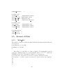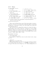
1
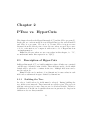
Univerzita Karlova v Praze
Matematicko-fyzikálnı́ fakulta
BAKALÁŘSKÁ PRÁCE
Viktor Mašı́ček
HyperCuts pro filtrovánı́ Linuxových paketů
Katedra aplikované matematiky
Vedoucı́ bakalářské práce: Prof. RNDr. Luděk Kučera, DrSc.
Studijnı́ program: Informatika
2006
Děkuji Prof. Luďkovi Kučerovi, za vedenı́ práce a pomoc při řešenı́ některých
problémů, převážně problémů týkajı́cı́ch se složitosti jak časové tak prostorové. Jeho pomoc byla velice přı́nosná.
Děkuji Dr. Lukáši Kenclovi, bývalému studentovi MFF, který nynı́
pracuje v Intel Research v Cambridge. Právě ve zmı́něném ústavu se zabývajı́
metodou HyperCuts. Jeho zásluhou jsem se o metodě také dozvěděl, za což
jsem mu vděčný. Také bych mu chtěl poděkovat za jeho pomoc při vedenı́
práce a za podnětné konzultace.
Jsem oběma vděčný za možnost pracovat na této bakalářské práci, která
byla velice zajı́mavá a přı́nosná.
Prohlašuji, že jsem svou bakalářskou práci napsal samostatně a výhradně
s použitı́m citovaných pramenů. Souhlası́m se zapůjčovánı́m práce a jejı́m
zveřejňovánı́m.
V Praze dne 10.8.2006
Viktor Mašı́ček
2
Contents
1 Introduction
1.1 Goal of the Work . . . . . . . . . . . . . . . . . .
1.2 Introduction to the Packet Classification . . . . .
1.3 Packet Classification by Multidimensional Cutting
1.4 Contents Overview . . . . . . . . . . . . . . . . .
.
.
.
.
.
.
.
.
.
.
.
.
.
.
.
.
.
.
.
.
.
.
.
.
8
8
9
11
12
2 PTree vs. HyperCuts
2.1 Description of HyperCuts . . . . .
2.1.1 Building the Tree . . . . . .
2.1.2 Traversing in the Tree . . .
2.2 Description of PTree . . . . . . . .
2.2.1 Building the tree . . . . . .
2.2.2 Traversing in the tree . . . .
2.3 Comparison PTree and HyperCuts
2.3.1 Rules and Fields . . . . . .
2.3.2 Choosing fields . . . . . . .
2.3.3 Data Structure Size . . . . .
2.3.4 Search Speed . . . . . . . .
2.3.5 Build/Update Complexity .
2.3.6 Comparison . . . . . . . . .
.
.
.
.
.
.
.
.
.
.
.
.
.
.
.
.
.
.
.
.
.
.
.
.
.
.
.
.
.
.
.
.
.
.
.
.
.
.
.
.
.
.
.
.
.
.
.
.
.
.
.
.
.
.
.
.
.
.
.
.
.
.
.
.
.
.
.
.
.
.
.
.
.
.
.
.
.
.
13
13
13
14
14
16
17
17
17
18
18
18
20
26
.
.
.
.
.
.
28
28
29
29
30
31
33
3 Theory
3.1 Using range match . . . . . .
3.2 Picking the Number of Cuts .
3.2.1 Definition of cut . . . .
3.2.2 All possibilities . . . .
3.2.3 Criteria of the Optimal
3.3 Optimization . . . . . . . . .
3
. . .
. . .
. . .
. . .
Cuts
. . .
.
.
.
.
.
.
.
.
.
.
.
.
.
.
.
.
.
.
.
.
.
.
.
.
.
.
.
.
.
.
.
.
.
.
.
.
.
.
.
.
.
.
.
.
.
.
.
.
.
.
.
.
.
.
.
.
.
.
.
.
.
.
.
.
.
.
.
.
.
.
.
.
.
.
.
.
.
.
.
.
.
.
.
.
.
.
.
.
.
.
.
.
.
.
.
.
.
.
.
.
.
.
.
.
.
.
.
.
.
.
.
.
.
.
.
.
.
.
.
.
.
.
.
.
.
.
.
.
.
.
.
.
.
.
.
.
.
.
.
.
.
.
.
.
.
.
.
.
.
.
.
.
.
.
.
.
.
.
.
.
.
.
.
.
.
.
.
.
.
.
.
.
.
.
.
.
.
.
.
.
.
.
3.3.1
3.3.2
Redundant Leaves . . . . . . . . . . . . . . . . . . .
Overlapping Rules . . . . . . . . . . . . . . . . . . .
4 User Manual
4.1 Directories Structures . . . . . . . . . . .
4.2 HyperCuts Program Functionality . . . .
4.2.1 Using ClassBench . . . . . . . . .
4.2.2 Generating and Write Rules . . .
4.2.3 Generating and Writing Packets .
4.2.4 Rules Format . . . . . . . . . . .
4.2.5 Match Packet . . . . . . . . . . .
4.3 How To Run the Program . . . . . . . .
4.4 Configuration File . . . . . . . . . . . . .
4.4.1 Example of the Configuration File
4.5 Format of Files . . . . . . . . . . . . . .
4.5.1 ”fields file” . . . . . . . . . . . .
4.5.2 ”rules file HC” . . . . . . . . . .
4.5.3 ”rules file CB” . . . . . . . . . .
4.5.4 ”packet file” . . . . . . . . . . . .
4.5.5 Menu . . . . . . . . . . . . . . . .
4.5.6 Possible Listing . . . . . . . . . .
4.5.7 Loging . . . . . . . . . . . . . . .
5 Programmer’s Manual
5.1 Modules . . . . . . . . . . .
5.1.1 ”HyperCuts.c” . . .
5.1.2 ”build tree.c” . . . .
5.1.3 ”config.c” . . . . . .
5.1.4 ”destroy.c” . . . . . .
5.1.5 ”error.c” . . . . . . .
5.1.6 ”generate packets.c”
5.1.7 ”loging.c” . . . . . .
5.1.8 ”prepare rules.c” . .
5.1.9 ”print.c” . . . . . . .
5.1.10 ”read.c” . . . . . . .
5.1.11 ”search.c” . . . . . .
5.1.12 ”tools.c” . . . . . . .
5.2 Main Structures . . . . . . .
4
.
.
.
.
.
.
.
.
.
.
.
.
.
.
.
.
.
.
.
.
.
.
.
.
.
.
.
.
.
.
.
.
.
.
.
.
.
.
.
.
.
.
.
.
.
.
.
.
.
.
.
.
.
.
.
.
.
.
.
.
.
.
.
.
.
.
.
.
.
.
.
.
.
.
.
.
.
.
.
.
.
.
.
.
.
.
.
.
.
.
.
.
.
.
.
.
.
.
.
.
.
.
.
.
.
.
.
.
.
.
.
.
.
.
.
.
.
.
.
.
.
.
.
.
.
.
.
.
.
.
.
.
.
.
.
.
.
.
.
.
.
.
.
.
.
.
.
.
.
.
.
.
.
.
.
.
.
.
.
.
.
.
.
.
.
.
.
.
.
.
.
.
.
.
.
.
.
.
.
.
.
.
.
.
.
.
.
.
.
.
.
.
.
.
.
.
.
.
.
.
.
.
.
.
.
.
.
.
.
.
.
.
.
.
.
.
.
.
.
.
.
.
.
.
.
.
.
.
.
.
.
.
.
.
.
.
.
.
.
.
.
.
.
.
.
.
.
.
.
.
.
.
.
.
.
.
.
.
.
.
.
.
.
.
.
.
.
.
.
.
.
.
.
.
.
.
.
.
.
.
.
.
.
.
.
.
.
.
.
.
.
.
.
.
.
.
.
.
.
.
.
.
.
.
.
.
.
.
.
.
.
.
.
.
.
.
.
.
.
.
.
.
.
.
.
.
.
.
.
.
.
.
.
.
.
.
.
.
.
.
.
.
.
.
.
.
.
.
.
.
.
.
.
.
.
.
.
.
.
.
.
.
.
.
.
.
.
.
.
.
.
.
.
.
.
.
.
.
.
.
.
.
.
.
.
.
.
.
.
.
.
.
.
.
.
.
.
.
.
.
.
.
.
.
.
.
.
.
.
.
.
.
.
.
.
.
.
.
33
34
.
.
.
.
.
.
.
.
.
.
.
.
.
.
.
.
.
.
36
36
37
37
38
38
38
39
39
39
40
41
41
42
43
43
44
46
46
.
.
.
.
.
.
.
.
.
.
.
.
.
.
48
48
49
49
49
49
50
50
50
50
50
50
50
51
51
5.2.1
5.2.2
5.2.3
5.2.4
The Maximum Allocated Memory . .
Main Variables . . . . . . . . . . . .
Definition of Fields and Set of Rules
The Tree . . . . . . . . . . . . . . . .
.
.
.
.
.
.
.
.
.
.
.
.
.
.
.
.
.
.
.
.
.
.
.
.
.
.
.
.
.
.
.
.
.
.
.
.
51
51
52
53
6 Conclusions
55
7 Future works
56
Bibliography
57
5
Název práce: HyperCuts pro filtrovánı́ Linuxových paketů
Autor: Viktor Mašı́ček
Katedra: Katedra aplikované matematiky
Vedoucı́ bakalářské práce: Prof. RNDr. Luděk Kučera, DrSc.
e-mail vedoucı́ho: [email protected]
Abstrakt: Filtrovánı́ paketů pomocı́ multidimensionálnı́ho štěpenı́ je jednı́m
z nových přı́stupů k této problematice klasifikace paketů. Základem je
vytvářenı́ stromu, který obsahuje zadaná pravidla pro filtraci. Matchovánı́
paketu je v tomto přı́padě podstatně rychlejšı́ než lineárnı́ procházenı́ všech
pravidel.
Metoda HyperCuts je jednou z nejnovějšı́ch metod založených na multidimensionálnı́ štěpenı́. Implementace této metody na prvnı́ pohled ukázala
jejı́ použitelnost. Závěrečné rozhodnutı́ o využitı́ programu HyperCuts v
praxi je však možné učinit pouze na základě výsledků testovánı́ v reálném
provozu.
Ve srovnánı́ s programem PTree, který je založen na metodě zvané TBF,
byl HyperCuts úspěšnějšı́. Srovnánı́ bylo prováděno spı́še z pohledu přı́stupu
k problému, než z implementačnı́ho pohledu nebo na základě úspěšnosti se
stejnými daty. Tam, kde bylo odkazováno na implementaci PTree, bylo
odkázáno i na naši implementaci HyperCuts. Srovnávána byla jak časová
tak prostorová složitost.
V teoretické části je zdůvodněno použitı́ formátu ”range match” (neboli
intervalového formátu). Také je zde definován pojem ”cut” (neboli řez),
který je velice výhodný pro počı́tánı́ složitosti jak časové tak prostorové.
Jednı́m z úkolů práce bylo implementovat metodu HyperCuts, a proto je
jejı́ součástı́ práce také uživatelský a programátorský manuál.
Klı́čová slova: klasifikace paketů, kontrola provozu sı́tě, vyhledávacı́ stromy
6
Title: HyperCuts for Linux packet filtering
Author: Viktor Mašı́ček
Department: Faculty of Mathematics and Physics
Supervisor: Prof. RNDr. Luděk Kučera, DrSc.
Supervisor’s e-mail address: [email protected]
Abstract: Filtering of packets by multidimensional cutting is one of the
new approaches to the solution of the packet classification problem. It is
based on creating a tree that contains the set rules of filtering. In this case
a packets matching is considerably faster than linear traversing of all rules.
The HyperCuts methods are one of the latest methods that use multidimensional cutting. At first sight the implementation of the HyperCuts
method demonstrated its utility. However, the final decision about the usage
of the HyperCuts program in practice can be made only on the basis of the
results of testing in it is necessary to can be using in a practice it have to
be tested in practical operation.
In comparison with the PTree program, which is based on the TBF
method, the HyperCuts program, was more successful. The comparison
was based on resolving the problem rather than on implementation aspect
or success with the same data. In case, where we use PTree source code
for confrontation, we compare it with source code of HyperCuts from our
implementation. We compare time and memory complexity.
In the theoretic part there is explain why the ”range match” was used.
There is definition of term ”cut” which is very advantageous for time and
memory complexity.
One of the goals of the work was HyperCuts method implementation,
thus it includes user and programmers manual.
Keywords: packet classification, network traffic control, tree-search methods
7
Chapter 1
Introduction
The main theme of this work is the packets classification. And what is
it? Many routers around the world exist. They connect many computers.
And many attacks are executed on these computers. Thus many firewalls are
installed into them. Routers and firewalls used some filters for routing or for
repulsing attacks. And the packets classification is using in some filters. For
better comprehension see Figure 1.1. Filters can visualize as in Figure 1.2.
Other usage of packets classification can be in Virtual Private Networks
(VPNs). In the network a lot of packets travel. These packets have to be
routed into correct computer in short time.
1.1
Goal of the Work
The goal of this work is to study new method HyperCuts [7], to implement it
and to confront it with the PTree program [1]. And what are HyperCuts and
PTree? The HyperCuts is new method in packet classification. On the other
hand the PTree is implementation one of the others methods. Both use a tree
structure for packets classification. Suppose we have a list of rules in filter.
In Linux, implicit method is linear traversing of them. But this method
is not very fast. On the other hand it is very simple for implementation.
This method is implemented in iptables which is standard program in each
distribution of Linux. Instead of linear traversing of the list, we build the
tree that contains these rules. Matching of packets should be much faster.
8
NET
NET
DROP
Figure 1.1: There are example of part of the Internet in the Figure. There are
routers, firewalls and some computers. Packets can be forwarded into computers or
they can be dropped. Routers only forward the packets. In routers and firewalls filters
are used.
1.2
Introduction to the Packet Classification
Suppose we have a list of rules in filter. The packet classification problem
is about determining the first matching rule for each incoming message.
Each rule consists of array of values. Array elements are called fields or
dimensions. In articles, both ”field” and ”dimension” denotation are used.
Some time, both names are used. All rules have the same number of fields.
So, we can imagine the set of rules as a table. Each row express one rule, each
column expresses one field. Fields can have one of three kinds of matches:
• exact match
• range match
• prefix match
The exact match in field is one number. The range match is an interval
of numbers. For better explanation of the prefix match, let us write down
values in fields in the binary notation. Values in fields are prefixes of a
9
NETWORKING SYSTEM
IN
OUT
CLASSIFIER
DROP
Figure 1.2: Simple demonstration of packet classifier is in the picture. Packets can
be forwarded or dropped.
numbers in the binary notation. For better imagination see the Table 1.1.
The character ’∗’ mean arbitrary value. The F ield1 has range < 0; 24 − 1 >
and the F ield2 has range < 0; 23 − 1 >.
type
Exact
Prefix
Range
rule
R0
R1
R2
F ield1
5
(10∗)2
1−7
F ield2
2
(∗)2
4−7
Table 1.1: Example of types of rules’ fields
There are some examples of real rules in the Table 1.2. Source and destination addresses are in prefix match (value/mask), source and destination
ports are in range match and flags are in exact match. In fact, flags are in
prefix match, but they have full masks all of them.
Note that the prefix match can be converted into the range match. On
the other hand, the range match cannot be converted into the prefix match
without dividing the rule into more rules. Of course, sometimes it is possible.
In the Table 1.1 the F ield1 of the rule R2 cannot be converted into the prefix
match. On the other hand, the F ield2 of rule the R2 can be converted (”4−7”
→ ”01∗”).
Many algorithms for packet classification exist nowadays. For example:
10
rule
R1
R2
R3
src. addr.
dst. addr.
src. port
dst. port
flags
87.214.184.182/8
186.252.138.127/9
48622-58651
16525-48629
0x58/0xFF
142.184.11.217/27
57.201.201.234/0
31079-59576
14458-50985
0x14/0xFF
157.186.165.152/7
3.22.187.194/3
7923-35081
32027-60008
0xa8/0xFF
Table 1.2: Example of real rules
• linear searching
• algorithm with precomputed earliest rules
• RFC [3]
• Hierarchical Cuts (=HiCuts [2])
• HyperCuts [7]
Most of these algorithms are based on the same idea. Prepare rules into
some own structures and for each incoming packet decide if the packet can
be sent along or if it must be dropped. See Figure 1.2.
1.3
Packet Classification by Multidimensional
Cutting
Fields in rules can be understood as dimensions. Each dimension is limited
by field’s definition, it means by interval. For example, the filed containing
source address is limited by interval < 0; 232 − 1 >. Rules’ fields can be
understood as subintervals in the dimensions.
The dimension can be divided into few parts, sub-dimensions. Thus each
rule belongs into one or more parts. Parts can be divided again and again.
Finally we create the tree. Each node contains definition of interval and
definition of dividing. Definition of interval in node is called region and
dividing is defined by cuts. Each part of the region created by cuts is called
sub-region. Each sub-region is a child of the node.
In Figure 1.3 are two dimensions. There is first node on the left side. It
is divided into four parts (A, B, C, D). There is a child node of part B on
the right side. It is divided into two parts (X, Y ). There is pointer from the
first node to the second node. The definition of interval in the child node is
the same as the interval that encloses the part B.
11
all dimension
subregion B
A
B
X
Y
C
D
Figure 1.3: Universal multidimensional cutting. In the Figure, there are one node
on the left side which consists of two dimensions. Each dimension contains one cut.
These cuts divide the node into four sub-regions, which point to child nodes. The
child node ”B” is demonstrated on the right side.
1.4
Contents Overview
Firstly we describe HyperCuts and PTree we compare them in the Chapter 2 ”PTree vs. HyperCuts”. Data structures, build complexity and other
characteristics are compared.
Next we describe some parts of HyperCuts in the Chapter 3 ”Theory”.
It contains new definition of cuts, which are usable in other theory. This
definition is better for implementation. It was come into exist during working
on this paper. Some optimizations are discussed too.
Chapter 4 contains User Manual of HyperCuts program. There are the
structure of directories, how we can program compiling, format of configuration file and using the program. There is part explicative logging main
data about trees that were built.
Finally there are Figure 5.1 showing dependencies of modules in the
Chapter 5 ”Programmer Manual”. There are descriptions of each module.
Main structures are described in this chapter, for better continuation in this
work.
12
Chapter 2
PTree vs. HyperCuts
This chapter describes the HyperCuts method [7] and the PTree program [1].
In the end, we confront methods even if HyperCuts is a theoretical method
and PTree is a program. We can do it, because PTree is in most cases
discussed from theoretical point of view. In case, where we use PTree source
code for confrontation, we compare it with source code of HyperCuts from
our implementation.
Note! In all cases where we use some values in this chapter, i.e. ”X”,
we understand under this expression as ”O(X)”.
2.1
Description of HyperCuts
In HyperCuts method [7], we build a multi-tree where all rules are contained
only in leaves. All rules consist of fields. These fields are used to decide which
branch will be selected to continue in the tree. Multiple field tests can be
used in each node.
Note! Fields can be understood as dimensions, because values in each
field enclose subinterval in space defined by dimensions.
2.1.1
Building the Tree
In order to build each node, fields must be selected. During building the
tree, fields create intervals. These intervals are called regions. The region is
split into sub-regions by cuts. Cuts are set for all selected fields. Therefore
in children node fields can be smaller then were in parent node. Regions in
children nodes are always smaller.
13
Fields greater than the mean of all of fields are selected as decision fields
for the current node. Afterwards cuts for all selected fields are set. In each
node same number of cuts is used. All cuts are distributed into selected
fields. In each node all possibilities of distribution of cuts are tested. To
decide which variant is better local heuristic is used, see paragraph 3.2.
Some optimizations are described in [7]. Two optimizations are used in
the program. The first optimization is following. We do not add a new leaf
if any identical leaf exists. Second optimization deletes rules from list of
rules during building the tree. Rules, which are covered by other rules, are
deleted. These rules cannot be matched. They will be discussed in 3.3.
2.1.2
Traversing in the Tree
Traversing in decision tree is very easy. In each inside node correct child is
selected for a consideration definition of regions an cuts in node. In leaves
we use linear searching. Special constant limits the number of rules in one
leaf. Thus, time required for linear searching in a leaf is inconsiderable.
Example
We have four rules. These rules are in the Table 2.1. Prefix match set rules.
In the Figure 2.1, we can see these rules drawn in dimensions X and Y. Note
that the rule ”R1” contains the rule ”R0”.
In the Figure 2.2, we can see rules that belong under each node. Assume
that leaves comprehend two rules. In the root node, both dimensions were
selected. On the right side, cutting being demonstrated. Branches ’1’, ’3’
and ’4’ point into leaves. Leaves ’3’ and ’4’ are empty. Branch ’2’ points on
the inside node. In this node, dimension Y was selected.
Assume that rule should be selected for the packet with these values:
P(X:10,Y:001). In the root node, the branch ’2’ is selected. In the next
iteration, the branch ’b’ is selected. In the leaf, the rule ”R1” is selected by
linear searching.
2.2
Description of PTree
The PTree project [1] is implementation of TBF filter into Linux kernel 2.4.
The basis of PTree is building a tree with information taken from rules. We
build the tree only at the beginning. If a new packet comes, we only traverse
14
R0
R1
R2
R3
X
11
1∗
0∗
1∗
Y
000
00∗
00∗
01∗
Table 2.1: Rules showed in the Figure 2.1
111
110
101
100
dimension Y
011
R3
010
001
R1
R2
000
R0
00
01
10
11
dimension X
Figure 2.1: In the picture, there are four rules which are show in two-dimensional
region. Their definitions are in the Table 2.1.
through the tree. We only need to rebuild the tree when we add new rules.
Traversing the tree in PTree and in HyperCuts is very similar. However,
building the tree is not.
Firstly, PTree uses only one field in all nodes in the tree. It is as in
HiCuts [2]. HiCuts is older than HyperCuts, but it is easier. On the other
hand, in PTree matched rules can be in all nodes and leaves in the tree. In
HiCuts and HyperCuts matched rules can be only in leaves.
Let us now look at fields; a set of all fields, which are included in all
rules, is prepared. Fields have to be ordered by their first bit in packet.
Some fields are not determined because their place in packet depends on
other fields. If a cycle does not come into existence in dependence fields,
we have no problem. In the opposite case, it is impossible to continue in
building the tree. After preparing a list of fields without a cycle, we can
15
root
3
4
1
2
R0,R1,R2,R3
1
2
4
3
a
R0,R1,R3
R2
a
R3
b
b
R0,R2
Figure 2.2: There is the tree in the Figure. We want match packet P(X:10;Y:001).
Definitions of rules are in the Table 2.1. In the root the branch ’2’ is selected. In the
child node the branch ’b’ is selected. On the right side cuts in the root and in the
child node is demonstrated. In the leaf the rule ’R1’ is selected by linear searching.
start with building the tree.
2.2.1
Building the tree
Each node in the tree has three sets of information:
• the node position - this position in packet is the same as field’s position,
which is used in this node
• a list of branches - each branch matches some value
• a list of rules that match at the node.
First, we determine the ”nearest” (closest to the start of the packet) field
in the set of rules. This determines the position of the node currently being
generated in the tree.
Now we have checked all rules in the set of rules whether they comprise
”nearest” field or not. If yes, then we check if there is already a branch with
the rule’s comparison value. Rules with a comparison value are included into
the right branch. New branches are created for rule without a comparison
value. If the rule does not compare at the ”nearest” field, then the rule is
included into a special wildcard branch. Special case is empty rule. This
16
rule is included into the match list in the node. When all rules from set of
rules are checked, all rules the form wildcard branches are copied into all
other branches. Because the rules in the wildcard branch do not compare at
the current node’s position, they must be available in every child node for
comparison. While rules are added to a branch, ”nearest” field is done off
of the rule. It is done, because this field is resolved in all rules.
Finally, we use recursion to create child nodes. For each branch, same
procedures with their set of rules are called.
This process continues while some rule comprises any field.
2.2.2
Traversing in the tree
For finding matched rule tree is traversed. In each node matched list is
copied into appropriate array. Next, we continue in matched branch. If
node does not have any child, then traversing the tree is stopped. Finally,
rules saved in appropriate array are printed.
2.3
Comparison PTree and HyperCuts
Values from following paragraphs are confronted in Table 2.3.
2.3.1
Rules and Fields
At first, we must compare rules and fields in HyperCuts and PTree. In
HyperCuts all rules have the same set of fields. So, some ”unneeded” fields
have wildcard value in some rules. On the other hand, in PTree all fields do
not have to be used in all rules.
Second difference is values in fields. In PTree a field can comprise of only
one value (it means one number). On the other hand, in HyperCuts a field
can be represented by interval. Thus, the PTree use exact match and the
HyperCuts use range match. So, if we take rules from PTree with the same
set of fields, we can make only one rule for HyperCuts. If some fields are
used in other rules and are not used in this rule, then unused fields can be
added with wildcard values.
17
2.3.2
Choosing fields
In the PTree, choosing the best field included in all rules is based on packets’
format. The algorithm takes field from the first to the last ordered by
position in the packet. It is good for linear reading of packet and for reducing
the list of fields. But, we can’t say it is the most optimal for height of the
tree. Optimization depends on types of fields. And mainly, rules’ format is
very important for optimal work of PTree.
In the HyperCuts, fields are selected for a consideration of their significance. It is discussed in 2.1.1. In short, fields those are higher than the mean
all of fields that selected. This variant is independent on packets format.
2.3.3
Data Structure Size
In [7] (Figure 18) we can see values which compare three types of databases
(ER-edge router, CR-core router and FW-firewall). Values are counted for
different number of rules. We get similar results for ER and CR. Memory
space is linear dependent on number of rules. But in FW case, we get
quadratic dependence. It is possible, that these results are not perfect, but
they are top estimates. Our implementation confirmed that the estimation
for ER and CR is approximately correct in most cases, which were examined.
In PTree method the situation is very different. In the worst case, we
can have a great deal of rules and all these rules include some field. It is
possible, that all rules include only this one field. In this case, tree will
include only one node with too much branches. But it is not the main
problem. Main problem is in number of rules. If we make too many rules,
then PTree method ends by breakdown. And memory for fewer rules is not
very interesting.
2.3.4
Search Speed
Search Speed - PTree
In PTree the search speed depends on the depth of the tree. The depth of the
tree is evident. If we take a rule with maximum number of fields considering
other rules, then the depth of tree cannot be bigger, because in each node
some field is done off. And the depth of tree cannot be smaller, because we
must use all fields included in rules. So, the depth of tree (marked DTP T ) is
DTP T = max (N umF (r)),
r∈Ruleset
18
where N umF (r) is number of fields included in rule r. Appropriate rule,
which had maximum number of field is marked RDT . Of course, we can find
more rules with maximum fields, but it is possible to mark any of those as
RDT .
However, the PTree method has one big handicap. Each node can include many branches. In the worst case, we must compare all values, which
correspond with branches. In each node there can be as much branches, as
are possible values for selected field in this node. So, this property is very
important for the search speed. In the worst case, in each node, which we
have traversed during the searching, we have all possible branches. Thus
the search speed (marked SSP T ) is sum all of fields in rule RDT :
SSP T =
X
IntF (f ),
f ∈RDT
where IntF (f ) is number of possible value of field f . For example, if f is
field containing a number of source port, then it has 216 possible values.
Search Speed - HyperCuts
In each inside node the constant number of cuts are used (marked as C). It
is independent of selected dimensions, see 3.2. By the definition of the cut,
each cut draws out one bit from one field (=dimension). Thus, first layer of
the tree draw out C bites. Children of the root of the tree are in the first
layer. In second layer next C bites are drown out, etc. Bites are drown out
from sum of number of bites all of fields. Thus, maximal depth of tree is
P
DTHC =
f ∈All f ields
N umBites(f )
,
C
where the N umBites(f ) is the number of bites defined the field f . For example, for field ”destination address” N umBites(DestAddr) = 32, because
destination address is defined as the 32 bites number.
All of was discussed with the assumption that only one rule is saved in
each leaf. If we allow saving more rules in leaves then dept of tree should be
smaller. Our implementation show, that in most cases the depth of a three
is smaller.
It is simply deciding which children should be selected in each inside
node, during matching in the HyperCuts method. In leaf is situation a little
different, but not more difficult. See pseudo code in paper [7] on page 221.
19
This operation can be doing in constant time considering the number of all
rules.
Thus we can say that search speed is same as the depth of the tree. The
search speed is marked SSHC .
P
SSHC =
f ∈All f ields
N umBites(f )
C
In comparison with SSP T is this better. In grain, SSHC differ from SSP T
in functions IntF () and N umBites(). For any values x
IntF (x) > N umBites(x) =⇒ SSP T > SSHC
2.3.5
Build/Update Complexity
In both methods we have two main results. Time needed to build one node
and number of nodes in the tree. For better comparison we confront both
results separately.
Building HyperCuts
They are two possibilities to count up the time needed to build one node.
The first is using pseudo code from [7] an page 220. The second is using
source code from our implementation. Both possibilities will be discussed.
Pseudo Code:
We describe pseudo code and counted time needed for build one node.
c1
D
c2
c3
D
c4
D
log2 (Dimi )
c5
√
spf ac ∗ R ∗ R
R
recursion
1
2
3
4
5
6
7
8
9
10
11
12
13
14
CreateNodeP(l1 , r1 , l2 , r2 , ..., lk , rk , Ruleset);
if (R < bucketSize) return;
for i ←− 1 to k do
Ni ←− numberOfUniqueValuesOnDim(Ruleset,i);
Mean ←− mean(N1 ...Nk );
for i ←− 1 to k do
S
if Ni > Mean then Dims ←− Dims {i};
for i ∈ Dims do
NC(i) ←− optimumNoCutsOnDimension(i, li , ri ,Ruleset);
Q
N ←− i∈Dims N Ci ;
for i ←− 1 to N do
(l1i , r1i , ..., lki , rki , Ri ) ←− createCut();
CreateNode(l1i , r1i , ..., lki , rki , Ri );
return;
20
All lines with constants ci are only some base instructions or we can
count this line by some simple formula. Ruleset is list of rules, li and ri
are values restrictive dimension i. Variable k is the number of dimensions,
we will rename this variable on D. Dims is set of dimensions and Dimi is
dimension i. Number of rules is marked as R.
The for-cycle on lines 3 and 4 runs through all dimension, in the worst
case. The function in cycle on line 4 only counts the number of unique values
in the dimension. It can be counted by ’ri − li + 1’.
Counted the mean all of input values is simple operation on line 5.
On lines 6 and 7 is for-cycle across all dimensions. For each dimension
we decide if it is grater then the mean or no. Insert dimension into selected
dimension is very simply.
The for-cycle on lines 8 and 9 runs through all dimensions, in the worst
case, and for each dimensions it count the optimal number of cuts. In the
worst case all possibilities must be trying. In paper [7] on page 219 is write:
”A set of iterations are executed; at each step the current value for nc(i) is
multiplied by two.”. So we can try only log2 (Dimi ) possible cases.
Line 10 is very simply.
Finally for each child the same function is called. The maximum number
of children is restrictive on page 219 (5.1.2) in [7]. The constant spf ac is
not very big number.
Then, the time needed to build one node (marked BNHC ) is
√
BNHC = c1 + D ∗ c2 + c3 + D ∗ c4 + D ∗ log2 (Dimi ) + c5 + spf ac ∗ R ∗ R
All constant can be vanished
BNHC = D + D + D ∗ log2 (Dimi ) +
√
R∗R
In general cases
R À D;
R À log2 (Dimi )
So these variables can by vanished too. Finally
√
BNHC = R ∗ R
Assume that the tree has not more leaves than rules approximately. In
another case the decision tree is √
feckless. Then the depth of the tree is
√
DTHC = logspf ac∗ R R. spf ac ∗ R marked as f (R). So, we can count
21
the number of nodes in the tree (marked N NHC ), because the number of
children is limited by f (R).
N NHC =
DT
HC
X
f (R)i
i=1
The sum can be counted as
N NHC = f (R) ∗
f (R)logf (R) R − 1
R−1
= f (R) ∗
=
f (R) − 1
f (R) − 1
√
R−1
√
.
spf ac ∗ R − 1
Considering the number of rules is big number in most cases, we can say
√
spf ac ∗ R .
√
=1
spf ac ∗ R − 1
= spf ac ∗
And of course
R∗
.
R−1=R
So, we can write
N NHC = R.
Source Code:
Following short source code of function ”build node()” from module
”build tree.c”. The listing contains main lines. Begin and end braces are
left out.
1 t_node* build node()
2
if(mv.binth >= number of rules) // LEAF
l1
3
leaf = add leaf()
l2
4
node->leaf = leaf;
5
return node;
6
else // INSIDE NODE
c1
7
init node();
8
choose dimensions();
D*d1+d2+D*d3
9
set number of cuts();
(C+D-1)!/((D-1)!*C!)
D
10
for(i=0; i < number of dimension; i++)
c2
11
size of cuts[i]=(dim[i].max)-(dim[i].min)+1)/regions;
spfac 12
for(i=0; i < number of children; i++)
D
13
for(k=0; k < number of dimension; k++)
22
c3
14
c4
15
c5
16
R
17
D
18
c6
19
c7
20
recur.21
22
23
// count min and max
new region[dimension[k].id].min = min;
new region[dimension[k].id].max = max;
for(j=0; j < number of rules; j++)
for(k=0; k < number of dimension; k++)
if((min r > max) || (max r < min)) include = FALSE;
if(include == TRUE) // include rule into the subset
children[i] = build node();
next dimension index();
return node;
Each line with c? or l? is simply to count. Number of dimension or
fields is marked D. We can mark both by one variable, because their values
are similar and some times they are the same. Number of rules is marked
R. And number of cuts is marked C. The constant spfac is not same as in
the article. In the code spf ac = 2C .
On line 8 are chose dimensions which are greater then the mean of size of
dimensions. For better understanding of D*d1+d2+D*d3 see module cuts.c.
On line 9 cuts are distributed into selected dimension. All possibilities
are tried. The (C+D-1)!/((D-1)!*C!) is number of all possibilities for gave
dimensions and cuts. For better understanding see Table 2.2.
For-cycles on lines 10, 13, 17 and 18 and their complexity are evident.
SOU RCE
Thus, all time need for build one node, marked BNHC
is
(C+D−1)!
SOU RCE
BNHC
+ D ∗ c2 + spf ac ∗
= c1 + (D ∗ d1 + d2 + D ∗ d3) + (D−1)!∗C!
(D ∗ (c3 + c4 + c5) + R ∗ ((D ∗ c6) + c7))
All constant can by vanished
SOU RCE
BNHC
=3∗D+
≈3∗D+
(C + D − 1)!
+ spf ac ∗ D ∗ (1 + R) ≈
(D − 1)! ∗ C!
(C + D − 1)!
+ spf ac ∗ D ∗ R
(D − 1)! ∗ C!
In general
D ¿ R,
so ”3 ∗ D” can be vanished and D in spf ac ∗ D ∗ R too
SOU RCE
=
BNHC
(C + D − 1)!
+ spf ac ∗ R
(D − 1)! ∗ C!
23
If we have too many rules and numbers of dimensions and cuts are standard, then (C+D−1)!
can be vanished. In consonance with Table 2.2 if we
(D−1)!∗C!
have a little dimensions and cuts, then
(C+D−1)!
(D−1)!∗C!
can be vanished too
RCE
BN aproxSOU
≈ spf ac ∗ R
HC
However, in the case when number of dimensions and cuts are greater
and number of rules is not too big, then we cannot vanish anything.
RCE
SOU RCE
Whether we counted with BN aproxSOU
or BNHC
it is better
HC
time then was counted with pseudo code, because
√
spf ac ¿ R
√
(C+D−1)!
can
be
vanished
as
compared
with
R too.
(D−1)!∗C!
Our implementation confirmed that estimation N NHC is approximately
correct in most cases which were examined.
(C+D−1)!
(D−1)!∗C!
spfac
2
4
8
16
32
64
128
256
512
C
1
2
3
4
5
6
7
8
9
1
1
1
1
1
1
1
1
1
1
2
2
3
4
5
6
7
8
9
10
3
3
6
10
15
21
28
36
45
55
D = Dimensions
4
5
6
7
8
4
5
6
7
8
10 15
21
28
36
20 35
56
84
120
35 70
126
210
330
56 126 252
462
792
84 210 462
924
1 716
120 330 792 1 716 3 432
165 495 1 287 3 003 6 435
220 715 2 002 5 005 11 440
9
9
45
165
495
1 287
3 003
6 435
12 870
24 310
10
10
55
220
715
2 002
5 005
11 440
24 310
48 620
Table 2.2: Distribution Cuts - All possibilities
Building PTree
If we evaluate main parts in code of PTree to build the tree (function
”PNODE buildNode(availRules *ruleset)” which is on lines from 224 to
592 in ”buildtree.c”), then we can count the BNP T . Follow short copy of
source code the buildNode function.
24
R
c1
c2
R
c3
c4
R
c5
R
c6
c7
c8
c9
R
IntF(f)
c10
c11
c12
c13
c14
IntF(f)
R
R
c15
c16
R
IntF(f)
R
recur.
1
2
3
4
5
6
7
8
9
10
11
12
13
14
15
16
17
18
19
20
21
22
23
24
25
26
27
28
29
30
31
PNODE buildNode()
for(index = 0; index < ruleset->length; index++)
if(ruleset->rules[index] == 0) count++;
if(count > 0)
for(index = 0; index < ruleset->length; index++)
if(ruleset->rules[index] == 0)
matched[count++] = ruleset->ruleNumbers[index];
for(index = 0; index < ruleset->length; index++)
ruleset->rules[index] == 0;
for(index = 0; index < ruleset->length; index++)
if(closest != index)
if(ruleset->rules[index] != 0)
if(compare([index],[closest]) < 0)
closest = index;
for(index = 0; index < ruleset->length; index++)
for(targindex = 0; targindex < numTargets; targindex++)
if(ruleset->rules[index]->val
== targets[targindex]->value)
targetAddRules(1);
if(targindex >= numTargets)
targetAddRules(1);
if(wildcards > 0)
for(index = 0; index < numTargets; index++)
targetAddRules(wildcards);
for(index = 0; index < ruleset->length; index++)
if(ruleNumbers[index] == wcrules[0])
targets[numTargets - 1]->size = ruleset->...;
targetAddRules(wildcards);
for(index = 0; index < numTargets; index++)
buildRuleset();
next = buildNode();
return ;
Lines with c? are simply to do them. IntF(f) mean number of possible
values of filed f. So,
BNP T = R ∗ c1 + c2 ∗ R ∗ c3 ∗ c4 + R ∗ c5 + R ∗ c6 ∗ c7 ∗ c8 ∗ c9 + R ∗ (IntF (f ) ∗
c10 ∗ c11 + c12 ∗ 13) + c14 ∗ (IntF (f ) ∗ R + R ∗ c15 ∗ c16 + R) + IntF (f ) ∗ R
All c? can be vanished
BNP T = 6R + 3 ∗ R ∗ IntF (f ) ≈ R ∗ (1 + IntF (f ))
Finally
BNP T = R ∗ IntF (f )
25
Next, we evaluate the number of nodes in the tree. As we know, the
depth of the tree in PTree is
DTP T = max (N umF (r)).
r∈Ruleset
We can limit the number of children in each node in the tree by
CH = min(( max IntF (f )), R).
f ∈F ields
So, the number of nodes is
N NP T =
DT
PT
X
CH i .
i=1
This sum can be counted as in last paragraph
N NP T = CH ∗
CH DTP T − 1
.
CH − 1
CH is great enough to vanish CH/(CH − 1). Thus,
N NP T = CH DTP T .
Because CH ≥ R then
N NHC < N NP T .
Finally, building one node in HyperCuts needs less time and PTree should
have more nodes. So, the tree should be built faster by HyperCuts method.
Update Complexity
The complexity of updating the tree is very simple. When the tree is updated, it needs be rebuilt in both methods.
2.3.6
Comparison
As it said, rules can be in all node in the PTree. However rules can be only in
leaves in the HyperCuts. On the other hand, it disadvantage of HyperCuts
method can be eliminate. In the paper [7] is discussed optimization ”Pushing Common Rule Subsets Upwards”. This optimization can be improved.
Finally, we can save rules in almost whole tree.
26
Matching
Decision Fields in Node
Search Speed
Data Structure Size
Build Complexity
Build one node
HyperCuts
in leaves
1
P or more
f
N umBites(f )
C
R or R
R∗
2
√
R or
+ spf ac ∗ R
R
rebuild the tree
(C+D−1)!
(D−1)!∗C!
Number of nodes
Update Complexity
PTree
in leaves and nodes
1
P
IntF (f )
uninterested or
breakdown
f
R ∗ IntF (f )
CH DTP T
rebuild the tree
Table 2.3: Comparative table
If we compare numbers of fields in nodes, then the HyperCuts method
has better result, because the PTree method cannot has more fields in one
node, but the HyperCuts method can has one or more fields in one node.
As was write in 2.3.4 about the Search speed. In comparison with SSP T
is SSHC better. In grain, SSHC differ from SSP T in functions IntF () and
N umBites(). For any values x
IntF (x) > N umBites(x) =⇒ SSP T > SSHC
What we can say about data structure size, if we are comparing the HyperCuts and the PTree? The PTree is breakdown for many rules. However,
the HyperCuts was not being tested in a real traffic. On the other hand, any
facts indicate on a problem with this. Thus, we can say that the HyperCuts
method is better than PTree method if we evaluate their data structures
size.
The paragraph 2.3.5 containing explanation of the build complexity. In
short, trees are built faster by the HyperCuts method.
Both methods have big disadvantages. If we can update the tree, it has
to be built anew and it does not very effective. One of topics in future works
should be to resolve this problem.
27
Chapter 3
Theory
In this chapter will be discussed why the range match was chosen for saving
rules. Next paragraphs are about cuts. There are definition of cut and
some demonstration of it on figures. There are paragraphs about using local
heuristic for distributing cuts into selected dimensions, too. Finally, some
optimizations used in the HyperCuts program are described.
3.1
Using range match
In the first versions of the HyperCuts program the prefix match was used
for inside saving rules. During traversing the tree it was not advantage, but
during linear traversing the leaf prefix match was advantage. On the other
hand, for building the tree it was not very advantageous. It was not reason
for changing prefix match to range match.
Some types of fields are normal writing in range match, for example
source and destination ports. These values had to be converting into prefix
match. And it is the problem. One rule containing for example source and
destination ports had to be converting into several ”prefix match rules”, because ports are normally saved as interval. Old module ’divided interval.c’
was used for this. This practise was not too optimal. The number of rules
grows up too much. Thus, complexity and memory grow up.
Finally, we used the range match for saving rules. If some fields are in
prefix match, then convert them into range match is very easy. The number
of rules is not changed.
28
3.2
3.2.1
Picking the Number of Cuts
Definition of cut
At the beginning, we explain what is the ”region”. In each node the region is
saved. The region is multidimensional interval. An example for n dimensions
can be < min1 ; max1 > × . . . × < minn ; maxn >.
We can divide the region. For example if we divide the region only in
the dimension i, two sub-regions grew up. We divide the region only in the
middle of a dimension.
An example of whole region is
< min1 ; max1 > × . . . × < mini ; maxi > × . . . × < minn ; maxn >
and two subregions are
< min1 ; max1 > × . . . × < mini ;
< min1 ; max1 > × . . . × <
maxi − mini
> × . . . × < minn ; maxn >
2
maxi − mini
; maxi > × . . . × < minn ; maxn >
2
Definition 1 - Cut: Assume that, we have region that is divided into
some sub-regions. One CUT will be operation which make double of these
sub-regions. Dividing each sub-region into two sub-regions does it. These
sub-regions have same quantity of interval in each dimension.
Assume that, we have region without cuts. We denote the number of
cuts C. If we make C cuts, then from one region grow up 2C sub-regions.
All sub-regions have same quantity.
Verification of correctness of our definition:
One cut is created by few hyperplanes of our region. These hyperplanes
are perpendicular with dimension in witch the cut is. And they are parallel
with each other dimensions. We have as hyperplanes as cuts.
Demonstration
The Figure 3.1 shows cuts in a two-dimensional region. The first part shows
using one cut in one dimension. The second cut (dot-dash) is added into the
same dimension in the second part. On the other hand, in the last part, cut
29
is added into the second dimension. The number of sub-regions doubles, in
both last two parts, because we used as hyperplanes as we have subinterval
in the selected dimension before adding. Each hyperplane cut through all
other dimensions.
q
q
q
q
q
q
q
q
q
q
q
q
q
q
q
q
q
q
2. cuts ⇒ 22 = 4 sub-regions
1. cut ⇒ 21 = 2 sub-regions
Figure 3.1: Cuts - 2 dimensions: On the left side, there is one cut in one dimension.
The cut divides the region into two sub-regions. On the right side, there are two
possibilities how we can add second cut. The second cut is show by dot-dash lines.
If we have region consists of three dimension situation is alike. It has not
to be clear that one cut in one dimension cut through all other dimensions.
And then the number of sub-regions doubles, see the Figure 3.2.
In the Figure 3.2, cut in the dimension ”X” cuts through dimensions
”Y ” and ”Z”. And cut in the dimension ”Z” cuts through dimensions ”X”
and ”Y ”.
The Figure 3.3 is analogical the Figure 3.2. However, the region consists
of four dimensions. Two cuts are showed, in dimension ”X”(lines) and
”W ”(grey layer).
3.2.2
All possibilities
If we build a tree, we use recursive function ”build node()”, see 2.3.5.Source
Code. At first, some dimensions are selected. Then the defined number of
cuts is distributed into selected dimensions. For better distributing, all
possibilities are tried. The number of possibilities depends on the number
of selected dimensions (marked D) and the number of defined cuts (marked
C). Number of possibilities are in Table 2.2.
30
Y
Y
Y
q q q
X
Z=0
Y
q q q
X
X
Z=max Z/2
Z=1
X
Z=max Z
Figure 3.2: Cuts - 3 dimensions: There are three-dimensional region. Two cuts
are demonstrated. The first cut is in the dimension ’X’ and the second cut is in the
dimension ’Z’. Cut in the dimension ’Z’ is show as the shaded plane.
Cuts are in sequence added into dimensions. We try all possibilities
and for each the decision-making function is called. The function returns
a evaluation of the possibility. The possibility with the best evaluation is
chosen. The decision-making function is described in next paragraph 3.2.3.
3.2.3
Criteria of the Optimal Cuts
Complexity of Picking
If we should build the best tree, during build the node we should build all
sub-trees (from the node) and use the best one. The best one means the
minimal depth and allocated memory together. This is not possible in the
real time.
Local Heuristic
Thus, a local heuristic are used. In each node, all possibilities of distributing
cuts into dimensions are tried. And the best is used, as was said in previous paragraph 3.2.2. The best possibility that is selected base on decisionmaking function.
31
Y
¡
¡
¡¡ ¡¡ ¡¡
¡ ¡¡ ¡
q q q Y
¡
¡
¡ ¡¡ ¡¡
¡
¡ ¡¡ ¡
¡¡Z
¡
W=0
X
¡
q q q Y
¡
¡
¡¡ ¡¡ ¡¡
¡ ¡¡
¡
Z
¡¡
¡
X
¡
W=max W/2
Z
¡¡
¡
X
¡
W=max W
Figure 3.3: Cuts - 4 dimensions: There are four-dimensional region and two cuts.
The first cut is in the dimension ’X’ and the second is in the dimension ’W’. For better
comprehension we recommend start in the Figure 3.1 and the Figure 3.2.
Decision-making function: Minimum Maximum and Minimum Sum
One possibility is one distribution of cuts into selected dimensions. For each
possibility all rules are traversed and for each sub-region, created by the
distribution of cuts, the number of rules, which fall into, are counted. The
maximum of these numbers is the main criteria. The second criterion is the
sum of all numbers fall into sub-regions. The maximum is marked M AX and
the sum is marked SU M . Thus, from all possibilities is used the possibility
with minimum M AX. If more possibilities with same M AX exists, then
the possibilities with minimum SU M is used. Finally, is more possibilities
with same SU M exists, and then any of these possibilities is used.
For better comprehension see Figure 3.4. The region consists of two
dimensions X and Y . There are four rules (R1 . . . R4). And there are three
cuts. Two cuts are in dimension X and one is in dimension Y . Sub-regions
are marked S0 . . . S7. Under each is number of rules fall into the sub-region.
This is one possibility distribution of cuts into dimensions. Thus, for this
possibility M AX = 3 for the sub-region S5 and SU M = 2 + 2 + 1 + 1 + 2 +
2 + 3 + 2 = 15.
32
S4
S5
2
2
R2
S6
S7
3
2
R4
Y
R3
S0
2
R1
S1
S2
S3
2
1
1
X
Figure 3.4: Decision-making function - one possibility: There are the region which
containes four rules. The region is divided into eight sub-regions that are marked
’S0’...’S7’. Each region contains different number of rules. These numbers are writing
in each region. For decision-making function the maximum number and sum of these
numbers are the most important information. For these Figure, the maximum number
is 3 the sum is 15.
3.3
Optimization
Two optimizations are used in the HyperCuts program. The first apply to
saving redundant leaves. The second apply to passing rules during build a
tree and their saving in leaves.
3.3.1
Redundant Leaves
Once, a leaf has to be created. The leaf contains a list of rules. If it is not
first leaf, then some leaf with same list of rules can exists. Without this
33
optimization, the new leaf, with same list of rules, is saved. It is not very
low-cost way.
Thus, before each adding new leaf is tested, if leaf with same list of rules
exists. If it exists, then the new leaf is created. If it does not exist, new leaf
is not created and the leaf address is change to address the already created
leaf. For better comprehending see the Figure 3.5.
NODE
Leaf:
R1
R1
NODE
Leaf:
R1
R1
Leaf:
R1
R1
Figure 3.5: In the case when two leaves have same list of rules then one of them is
deleted. The pointer of the deleted leaf is changed on the pointer to second leaf.
3.3.2
Overlapping Rules
For build a tree the recursive function for build one node is called. A list
of rules is one of input variables of this function. After selected dimensions
and distributing cuts, new lists of rules are created for each child. These
lists are created from the input list of rules.
Each node is limiting by region. It cans possible, that in the region some
rule is covered by another rule. If covered rule has less preference than the
second rule, then it is not possible match any rule with the covered rule in
the sub-tree started in this node.
Thus, each list of rules intended for child nodes is traversed and all rules
covered by any other rule with greater preference is deleted. For better
comprehending see Figure 3.6.
34
R4
R4
R1
R1
R2
R2
R3
Figure 3.6: There are four rules in the region. As we can see, there is the rule
’R3’ which does not be matched any time because the rule ’R2’ with bigger priority
covered it. Thus we can delete the rule ’R3’ from this region. On the other hand the
rule ’R1’ is not deleted while it is covered by the rule ’R2’ because the rule ’R1’ has
bigger priority than the rule ’R2’.
35
Chapter 4
User Manual
Next paragraphs describe using the HyperCuts program and format main
files. It contains some examples for better understanding.
The HyperCuts program is able to use programs from ClassBench [8]
project. The ClassBench is not contained in the HyperCuts program. The
ClassBench can generate random rules and packets. The ClassBench can be
download from [8].
4.1
Directories Structures
In the ’./’ are following files and directories: ’./src/’, ’./log/’, ’./doc/’,
’./Readme’ and ’./Change.log’.
There are sources files, header files, ’Makefile’ and configuration file
(’config’) , in ’./src/’. And file containing menu. In this directory there
is subdirectory called ’./tmp/’, which is used in default configuration file.
But this directory is not necessary for running the HyperCuts.
The ’./log/’, is directory intended for making logfiles after building
trees.
This documentation is included in the ’./doc/’ directory.
The ’./Readme’ file includes some information at the begin. The list
of program’s features, the list of files and directories necessary for running
the program, the list of files necessary for generating random rules and
the list of files necessary for generating random packets are included in the
’./Change.log’ file.
36
4.2
HyperCuts Program Functionality
Program can:
• read fields and rules
• generate random rules by ClassBench program [8], see 4.2.1
• builds the tree - during build each node:
– select dimensions
– set number of cuts, see 3.2
• traverses the tree and match packets
• prints tree, leaves etc. into file or console
• sets main variables in configuration file
• uses some optimization, see 3.3
• logs data about building the tree
4.2.1
Using ClassBench
What is the ClassBench [8]? It is the project and software, which generates
rules as representative of a typical Internet rule base and simulates real
traffic on the Internet. It does not containing any filter or other similar
program.
At the first, it generates rules as representative of a typical Internet
rule base. Output rules depend on many variables, which you can define.
You have to define ”seed-file”, which define quality of output rules. Some
examples files are contained in the ClassBench project, for example the file
’acl1 seed’.
At the second, it generates packet headers as representative of typical
Internet traffic. Some variables are defined as switches. The main switch
is a name of the file with rules. It is necessary, because packet headers
are generated specially for these rules. Packet headers match witch rules in
many cases. It is for better testing rules. However, some packet headers do
not match with any rules.
37
We can generate random rules and packets, if we add ’db generator’ and
’trace generator’. They are expected in directory where the executable file
’hypercuts’ is. They are included in ClassBench project, see [8]. The file
’acl1 seed’ is necessary for generating rules, too. This file is expected in
subdirectory ’Data’. It is a part of ClassBench.
The HyperCuts can run without executable files ’db generator’ and
’trace generator’, but without generating random rules and packets. Thus,
if you can generate random rules, download the ClassBench from [8].
4.2.2
Generating and Write Rules
It is possible to generate random rules, but not all types of rules. For
generating random rules use executable file ’db generator’. It generate
rules in ClassBench format, see 4.2.4.
After that, we can transform rules into HyperCuts format. It is possible
write rules by hand in either format. Names of files with rules are defined
in configuration file. If you write rules in HyperCuts format, then field
definitions must be set manually.
4.2.3
Generating and Writing Packets
It is possible to generate random packet headers. For this, ’trace generator’
is necessary. It generates random packet headers for a consideration list of
rules. It generates packets, which mach with rules in general case.
Of course, it is possible to write packets values by hand. Packets are
written in file defined in a configuration file. For format of these files see
4.5.4.
4.2.4
Rules Format
In the HyperCuts program two format of rules are used, the HyperCuts
format and the ClassBench format.
Rules - HyperCuts Format
A rule consists of fields. Each field has got two values - minimal and maximal
value. These values enclose interval of possible values for the rule in this
field. HyperCuts format does not differentiate types of fields.
38
Rules - ClassBench Format
ClassBench format differentiates types of fields. For different fields it has
different formats. For ports ClassBench has same format like HyperCuts
- intervals. For example ”15565:36487”. For addresses, it has got other
format. Address has got two values - value/mask. The value is set in
standard address format - ” ∗ . ∗ . ∗ . ∗ ”. The mask is a number, for example ”85.195.169.121/10”. Protocol and flags are set in the same way as
addresses, but in hexadecimal, for example ”0x26/0xFF”.
4.2.5
Match Packet
If packet headers are defined, matching is possible. For each packet, the tree
is traversed and the matching rule is printed. We can print matching rules
into the file or into ’standard output’.
4.3
How To Run the Program
Change directory-to-directory containing the program in order to build the
HyperCuts. Then type ”make”. If you want to delete object files, then type
”make del obj”. If you want to delete object files and output file, then type
”make clean”.
Usage: hypercuts [-c file | -h | -v]
-c file
Define configuration file. If option "-c" is not used, then
default configuration file ("./config") is used.
-h
Print this help.
-v
Print version, date and time of compilation.
4.4
Configuration File
In this file, all-important constants are set. Each constant has to be on
separate line. Lines beginning with ’#’ and empty lines are ignored.
We can set the maximum number of dimensions used in a node (it is
designates as ”max dimension”) and the maximum number of rules saved
39
in one leaf (”binth”). The number of cuts (”number of cuts”) is set in the
configuration file, too. This number is used for picking the number of cuts,
see 3.2.
The program can generate random rules. It uses the program ClassBench. Rather ”db generator”, which is one of more ClassBench’s subprograms. The number of rules generated by this program is set in the
configuration file too (”num rules”). However, these rules must be transformed into the HyperCuts format. If the variable ”random generate” is
not set to the digit ’1’, then generating new rules is not allowed.
We can set path of files for definitions of fields (”fields file”), definitions of rules in the HyperCuts format (”rules file HC”) and for the
ClassBench format too (”rules file CB”). Packet values in the HyperCuts
format are saved in the variable ”packet file”. Format of these files is
described in 4.5. When a tree is built, it can print. The tree can be printed
into a file or into the console (it means the standard output). It can be
printed in two formats: depth or breadth. The tree is printed into the file,
defined in the configuration file (”tree output”). Last two directives are
used to define the output for search matching rule (”search output”) and
for the list of all leaves (”leaves output”). Both can be printed to the
console too.
There are two variables, which enable and disable two optimizations.
There are ”opt01 leaves” and ”opt02 overlap”. If they are set to the
digit 1, they are enabled.
Reading files, printing tree etc. is described in the chapter about the
Menu (4.5.5).
4.4.1
Example of the Configuration File
# restrictive number of dimensions
max dimension 9
# restrictive number of rules in leaf
binth
2
# set number of cuts in dimension during building the tree
4
number of cuts
# for rules generated by ’db generator’
num rules 100
40
random generate
1
# input file
fields file
./tmp/random.fields
rules file HC ./tmp/random.rules
rules file CB ./tmp/rules.db
packet file
./tmp/rules.db trace
# output file
tree output
./tmp/random.tree
search output ./tmp/random.search
leaves output ./tmp/random.leaves
# optimization
opt01 leaves
1
opt02 overlap 1
4.5
4.5.1
Format of Files
”fields file”
The number of fields is defined at first. Each line starting with the character
’#’ is ignored.
# definition of fields
# number of fields
5
After that, for each field one value is defined. From the value range is
generated. Minimal value is ’0’ and maximal value is ’2P OW ER ’, where the
POWER is the value. Each field is defined on a separate line.
# on each line the power is written => min=0 and max=2^power
# in future - if more values are written, these values are ignored
32
32
16
16
8
41
4.5.2
”rules file HC”
The number of rules is defined at first. Each line starting with the character
’#’ is ignored.
# definition of rules
# number of rules
1703
After that, for each rule minimal and maximal vales of range are defined.
And actions are defined too. Each rule starts with lines:
# [describe]
Next lines define minimum and maximum values for each field:
[minimum]tabulator[maximum].
The last line contains string-defining action.
# each rule consist of
# lines defining min. and max. for each field and
# one line defining action (now only name of action)
# r0
2147483648 4294967295
2772403712 2772404223
52333
64681
18349
27196
248 248
R0
# r1
4056108560 4056108575
3399358560 3399358591
11564
32655
39246
45506
145 145
R1
# r2
3221225472 4294967295
1480978816 1480978943
43623
45674
52870
57491
157 157
42
R2
..
.
etc.
4.5.3
”rules file CB”
Each rule starts with the character ’@’. These values are following:
[source address]/[mask]tabulator
[destination address]/[mask]tabulator
[minimum source port]:[maximum source port]tabulator
[minimum destination port]:[maximum destination port]tabulator
[protocol]/0xFF
[other values]
All values are on one line. The HyperCuts program ignores other values
at the end of the line.
@85.195.169.121/10 135.178.232.122/18 15565:36487 19361:55061 0x26/0xFF x455b/0x6bd9
For more details see the ClassBench documentation [8].
4.5.4
”packet file”
Values for all fields are on one line, for each packet. tabulator separates
values. For example:
3505766400
3600809983
2731320831
..
.
etc.
1450749503
4294967295
2684712703
45927
36226
11535
33618
48076
55099
43
10
53
28
4.5.5
Menu
********** MENU **********
0 - show menu
| 5 - print tree (= 51)
10 - exit
|
51 / 52 - depth - stdout / file
1 - read fields & rules
|
53 / 54 - bradth - stdout / file
11 / 12 - read fields / rules
|
55 - print tree depth
2 - build tree
|
56 - print leaves - stdout
3 - match packets (= 31)
|
57 - print leaves - file
31 / 32 - stdout / file
|
58 - print number of leaves
33 - generate random packets
| 6 - generate random rules - HC
4 - print fields & rules
|
61 - generate random rules - CB
41 / 42 - print fields / rules
|
62 - transform rules - CB => HC
43 - print number of fields
| 7 - print main variables
44 - print number of rules
|
71 / 72 - set - default / config
------------------------------------------------------------------------8 - testing => generate rules and packets, read fields and rules,
build tree and match packet
**************************
Menu controls the HyperCuts program. In the menu, number is assign for
each action. The action is executed after writing this number and pressing
the Enter key. The menu is written only after starting the program and
after writing the digit ’0’.
After each action, the command line is written. It contains some important information, three letters, between two characters ’*’ (*???*), signify
if fields and rules were read and if the tree was built. The ’F’ means that
definitions of fields were read, the ’R’ means that rules definitions were read,
the ’T’ means that tree was built and the ’N’ means NOT. Thus, possible
variants are *NNN*, *FNN*, *FRN* or *FRT*.
Description of actions:
1 - read fields & rules
11 / 12 - read fields / rules
Read definitions of fields and/or rules from files defined in the configuration file.
2 - build tree
Build the tree from defined rules.
Note! During build the tree memory are allocated. All allocated memory is counted. If allocated memory go over 100MB, the building the tree
is stopped. This value can be changed, see 5.2.1. If the building the tree is
44
stopped, then memory is free. During the building the tree each 1MB is
indicated by printing ’.’ on console. This valued can be modified too.
3 - match packets (= 31)
31 / 32 - stdout / file
33 - generate random packets
Traverse the tree and find the first matching rules for each packet. The
path to file with packets is defined in the configuration file. The action
’33’ generates packet headers into the files defined in the configuration file.
In order to generate new packet headers, ’./trace generator’ must be in
directory which containing executable file ’hypercuts’.
4 - print fields & rules
41 / 42 - print fields / rules
43 - print number of fields
44 - print number of rules
5 - print tree (= 51)
51 / 52 - depth - stdout / file
53 / 54 - breadth - stdout / file
55 - print tree depth
56 - print leaves - stdout
57 - print leaves - file
58 - print number of leaves
Print some information (fields, rules, tree, leaves) to the console or into
files defined in the configuration file. Output files, which are used for printing, are defined in configuration file.
6 - generate random rules - HC
61 - generate random rules - CB
62 - transform rules - CB => HC
Generate random rules in the HyperCuts or in the ClassBench format
(see chapter 4.2.4 and 4.2.4), or transform rules from the ClassBench into
the HyperCuts format.
7 - print main variables
71 / 72 - set to default / by config
Print or set main variables. At the beginning of the program, the configuration file ’./config’ is used, if it exists. If it does not exist, the default
values are used. Other configuration file can be specified by flag ’-c’, see
4.3. By ’71’ main variables are set to default values. By ’72’ main variables
are set by specified configuration file (’./config’ or ’-c file’).
45
8 - testing => generate rules and packets, read fields and rules,
build tree and match packet
It is action for testing the program. It can be understood as ”multiaction”. It is the same, as you it do these actions:
------6 - generate random rules - HC
33 - generate random packets
1 - read fields & rules
2 - build tree
32 - match packets - file
-------
Example: Write ’71’ to set all possible main variables, not only defined in
the configuration file, to default values. After that, write ’1’ to read fields
and rules. To build the tree writes ’2’. Finally print the tree. Print it to
depth to the console by typing ’51’.
4.5.6
Possible Listing
After majority commands, some information is written to the console. The
string ”Err:” starts listing errors.
4.5.7
Loging
After building the tree main values are saved in the ”./log/build tree.log”
file. There are number of fields, rules and cuts, binth, optimization setting,
depth of tree, number of leaves, allocated memory and name of files which
containing definition of fields, rules and packets about each build tree, in this
file. Files with definition of fields, rules and packets are saved in ”./log/”
too.
There is the example of information about one tree:
***** HC-1.4 - building tree ***
number of fields = 5
number of rules = 1000
number of cuts = 4
binth = 10
optimization - leaves = 1
optimization - overlap = 1
building time = 0.050 [sec]
46
depth = 4
number of leaves = 2116
memory (by malloc) = 627.82 KB
file with fields = ’463876362.fields’
file with rules = ’463876362.rules.db’
file with packets = ’463876362.packets’
********************************
Files with fields, rules and packets are in ”./log/” directory, too.
47
Chapter 5
Programmer’s Manual
This chapter is intended for developer that will continue with HyperCuts
implementation. There are describing main structures, all modules and some
interesting parts of code.
5.1
Modules
bild_tree.c
generate_packets.c
loging.c
error.c
cuts.c
print.c
HyperCuts.c
Legend:
config.c
A.c
B.c
tools.c
read.c
A.c depends on B.c
destroy.c
search.c
prepare_rules.c
Figure 5.1: Dependencies of modules
Of course, modules use some our structures. These structures are described in chapter 5.2 (”Main structures”). Refer to this section for better
comprehension.
48
5.1.1
”HyperCuts.c”
This is the main module. Main variables, the root tree, the definition of
fields, the set of rules, the list of leaves etc. are defined in this file. These
variables use other modules for building the tree, printing the tree, the leaves
and for other actions. Modules are mainly called from the menu.
5.1.2
”build tree.c”
This module contains functions for building the tree. The ”build tree()”
is function called to build the tree, but it is not main function in this module.
It only calls the function ”build node()”.
The function ”build node()” is the most important function in this
module. It is the recursive function. At first, it decides whether the node is
a leaf or not. If rules which are incoming into the node are smaller than the
variable ”binth”, then a new leaf is created. In other cases, a new inside
node is created.
For the inside node, dimensions must be selected and for all dimensions
a number of cuts must be set. The sum all of cuts is defined in the configuration file. The ’cuts.c’ module is used for the optimal distribution of cuts
into selected dimensions, see 3.2. Finally, the function calls itself for each
child. The input rules for each children node are rules, which fall into the
appropriate sub-region.
This module uses module ”destroy.c”. When the tree cannot be completely built, then we must free the memory, which has already been allocated. Thus module also uses some assistant function from ”tools.c”.
5.1.3
”config.c”
This module is used for reading and setting main variables from the configuration file. It can set main variables to default values and print them to
the standard output.
5.1.4
”destroy.c”
Module used for freeing allocated memory - memory allocated for the set of
rules, the tree etc.
49
5.1.5
”error.c”
It is instrumental to printing all error and warning in the program. Thus,
almost all modules depend on this module. It contains one main function
and some macros that used this main function.
5.1.6
”generate packets.c”
This module generate random rules base on rules. For the generating the
program ”trace generator” is used.
5.1.7
”loging.c”
After build the tree, the function from this module is called. It saved important information about the tree. And copy files with fields, rules and
packets.
5.1.8
”prepare rules.c”
In this module there are located function for generating new rules by the
ClassBench, see 4.2.4, and transforming these rules into the HyperCuts format. The ClassBench generates rules containing values set by values/mask.
Thus, these fields are transformed into the HyperCuts format (interval format).
5.1.9
”print.c”
This module is used for printing rules, the tree, leaves and other information.
Some functions can print into a file as well as into the standard output.
5.1.10
”read.c”
The module is used for reading the definition of fields, the set of rules and
values of packets from files. Path of files are set in the configuration file.
5.1.11
”search.c”
There are three functions in this module. The ”match all packets” passes
all packets and for each it calls ”search leaf()”. The ”search leaf()”
50
gets packet values and the root of the tree. It traverses the tree and finds the
leaf, which can contain the matching rule. After that ”match all packets”
calls the ”traverse leaf()”. The ”traverse leaf()” decides, whether
the rule is really saved in leaf. If rule is not in the leaf, then the rule is not
in the set of all rules. In this case the packet does not match for any rules.
5.1.12
”tools.c”
This module contains assistant functions. E.g. the function ”get depth()”,
which gets the root of the tree and returns depth of the tree.
5.2
5.2.1
Main Structures
The Maximum Allocated Memory
During build the tree memory are allocated. All allocated memory are
counted. If allocated memory go over 100MB, the building the tree is
stopped. This value is set in #define MAX MEMORY. It is in ”bytes”. You
can change this value and recompile the program. During the building the
tree each 1MB is indicated by printing ’.’ on console. This valued can be
modified too. It is saved in #define PRINT SUB MEMORY. It is in ”bytes”
too.
5.2.2
Main Variables
The structure for main variables:
typedef struct{
int max dimension;
int spfac;
int binth;
int number of cuts;
building the tree
int num rules;
// restrictive number of dimension
// restrictive number of children
// restrictive number of rules in leaf
// set number of cuts in dimension during
// for generating rules by ’db generator’
int random generate;
51
// NULL ... stdout/stderr/stdin
char *fields file;
char *rules file HC;
char *rules file CB;
char *packet file;
char *tree output;
char *search output;
char *leaves output;
int opt01 leaves;
int opt02 overlap;
}t main var;
We have two variables of the type ”t main var” in the HyperCuts program. One for the actual tree, because we need these values in order to
printing and destroy it etc. Of course, if the tree was built. And we need
one variable for new values that are read from the configuration file. When
a new tree is build, old values are replaced by the new values.
5.2.3
Definition of Fields and Set of Rules
We use the ”t field”, the ”t interval” and the ”t rule” types for saving
the definition of fields and the set of rules.
typedef unsigned int INTERVAL;
// general information about field
typedef struct{
INTERVAL min, max;
// minimum and maximum value of field
int power;
// value set in file with field definition
}t field;
typedef struct{
INTERVAL min, max;
}t interval;
// information about rule
52
typedef struct{
int id; // rule index in set of all rules
t interval *interval; // array of fields’ intervals (min and max)
char *action; // information about rules action
}t rule;
The definition of fields is the array of the ”t field” and the set of rules
is the array of the ”t rule”:
// variables for read structures
// rules
t rule *ruleset = NULL;
int number of rules = NOT DEFINED;
// fields
t field *field def = NULL;
int number of fields = NOT DEFINED;
// root of tree
t node *root = NULL;
5.2.4
The Tree
Types ”t dimension” and ”t node” are used for saving the tree.
// information about dimension=fields in node
typedef struct{
int id;
// dimension’s index
int cuts;
// number of cuts in dimension
INTERVAL min, max;
// minimum and maximum value of dimension
}t_dimension;
typedef struct node{
// array with all dimensions used in node
t_dimension *dimension;
// children=branches in array
//
not multidimensional
//
=> special function for count of selected child
//
array of pointer
struct node **children;
53
// pointer to leaf
//
== NULL ... this node is not leaf
//
!= NULL ... this node is leaf
//
=> we don’t need dimension[], pointer to leaves
t_rule **leaf;
}t_node;
The root of the tree is of the ”t node” type.
One leaf is list of pointers to rules in the array ”*ruleset”. Each list
is ended with a NULL pointer. And the ”t leaves” is list this leaves. The
list of leaves is ended with a NULL pointer, too. Thus, the leaves is the
list of the list of pointers to the list of rules (”t rule ***leaves;”). See
the Figure 5.2, for better idea.
ruleset
r
leaves
r
?
?
r r r
Y
H
H
k
Q
Q H
¤
@
Q H
¤
@
H
Q H
@
R
Q ¤²H ?
yX
X
XXXQr Hr
XX r
r X
»
»
»»»
9
»
r
r
³³ ©©
³
³³ ©©
)
³
©
©
¼©
©
NULL
NULL
NULL
Figure 5.2: Connection of ruleset and leaves: We have the list of rules which
is saved in the array ’ruleset’. It is on the left side in the Figure. We use the
array ’leaves’ for saving the list of leaves. Each element of array leaves’ is array of
pointer to rules. It is on the right side.
54
Chapter 6
Conclusions
The HyperCuts [7] method was implemented in user space in a Linux. This
first step is important. The HyperCuts can be tested and results of these
tests can decide about future using of HyperCuts. At first blush, we can say
the HyperCuts is usable and it should be interconnected with Linux Kernel
2.6.
It can build tree very effectively in comparison with the PTree [1]. Both,
the HyperCuts and the PTree were discussed and their complexities and
structure sizes were compared. From these two methods the HyperCuts
have better results.
The HyperCuts program is not small; hence large part of this work is
programmer’s manual. Structures and modules were described. The user
manual is contained too. For testing the HyperCuts we recommended the
ClassBench project [8]. The HyperCuts program is prepared for using it.
The HyperCuts theory was be described too. The new definition of a
cut was defined. It is like a cut in the paper about HyperCuts [7], but it is
usable in a code and it is better for counting complexities etc. However, the
cut in the paper is very universal and our definition is done especially for
the HyperCuts implementation.
One of old HyperCuts versions generated some trees. These trees were
used for testing and comparison with other methods. It was describe in
paper [5]. The HyperCuts had good results.
Finally, we can say that the multidimensional cutting for the packet
classification is a good way, especially the HyperCuts method.
The HyperCuts program can be downloaded from:
”http://www.ms.mff.cuni.cz/∼masiv3am/HyperCuts”.
55
Chapter 7
Future works
First what we can do in the future is interconnecting the HyperCuts program
with Linux Kernel 2.6. The first way is do separate kernel module. The
second way is use Iproite2 [4] which is a set of programs for net-filtering and
it contains API for creating new-filter. This filter can be used with other
filters. This way is difficult, but more usable. The good work that describes
some part of Iproute2 is Czech thesis [6].
Next step should be to implement next optimizations. Some optimizations are describe in paper [7]. However, the more, the better.
The HyperCuts should be tested in a real traffic and it is important to
dare some long time tests of the program. At the end of this testing should
be review or table of main variables used in the HyperCuts and dependencies
tree on these variables.
The local heuristic is used for distributing cuts into selected dimension
during build node. However, decision should be done with respect to optimal
relations in the whole tree.
The big disadvantage of HyperCuts program is update complexity. We
have to rebuild a tree if we have to add any rule. Thus, how we can add new
rule without rebuild whole the tree? Working on answering this question
should follow.
56
Bibliography
[1] Derek Becker, Radivoje Todorovic, Qihen Wang: PTREE: A System for Flexible, Efficient Packet Classification, CS524, Spring 2001,
”http://www.chen-becker.org/wustl/work/tbf/”
[2] P. Gupta, N. McKeown: Packet Classification using hierarchical intelligent cutting, in Proc. Hot Interconnects, 1999
[3] P. Gupta, N. McKeown: Packet classification on multiple fields, in SIGCOMM 99, 1999
[4] Stephen Hemminger, Alexey Kuznetsov: Iprote2 project,
”http://developer.osdl.org/dev/iproute2
[5] L. Kencl and C. Schwarzer: Traffic-adaptive packet filtering of Denial
of Service attacks, in Proceedings of IEEE WoWMoM Workshop on
Autonomous Communication and Computing (ACC), Niagara Falls,
NY, USA, June 2006.
[6] Jakub Mácha:
Diplomová práce - Kontrola sı́ťového provozu,
Masarykova Universita,
Fakulta Informatiky,
Brno 2000,
”ftp://ftp.linux.cz/pub/linux/people/jakub macha/traffic-control.ps”
[7] Sumeet Singh, Florin Baboescu, George Varghese, Jia Wang: Packet
Classification Using Multidimensional Cutting, Proceeding of SIGCOMM, Karlsruhe, Germany, 2003
[8] D. E. Taylor, J. S. Turner: ClassBench project: A Packet Classification
Benchmark, Washingtom University in Saint Louis, Applied Research
Laboratory, ”www.arl.wustl.edu/∼det3/ClassBench/”
57