1
I
2002 IMPREZA SERVICE MANUAL
QUICK REFERENCE INDEX
~
TRANSMISSION SECTION
c-
-
This service manual has been prepared
to provide SUBARU service personnel
with the necessary information and data
for the correct maintenance and repair
of SUBARU vehicles.
This manual includes the procedures
for maintenance, disassembling, reassembling, inspection and adjustment of
components and diagnostics for guidance of experienced mechanics.
Please peruse and utilize this manual
fully to ensure complete repair work for
satisfying our customers by keeping
their vehicle in optimum condition.
When replacement of parts during
repair work is needed, be sure to use
SUBARU genuine parts.
All information, illustration and specifications contained in this manual are
based on the latest product information
available at the time of publication
approval.
FUJI HEAVY INDUSTRIES LTD.
G1830BE4
1
CONTROL SYSTEMS
CSr
1.
2.
3.
4.
5.
6.
7.
8.
9.
c-
.
Page
General Description .................................................................................... 2
Electrical Component .................................................................................. 6
AT Shift Lock System .................................................................................. 8
23
Select Lever ..............................................................................................
Select Cable .............................................................................................. 26
AT Shift Lock Solenoid and “P” Position Switch ........................................ 29
Integrated Module ..................................................................................... 31
MT Gear Shift Lever .................................................................................. 32
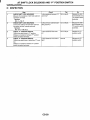
General Diagostic......................................................................................
38
I
GENERAL DESCRIPTION
CONTROL SYSTEMS
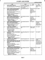
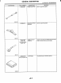
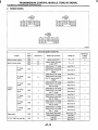
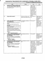
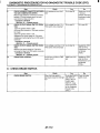
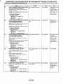
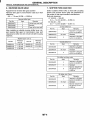
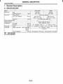
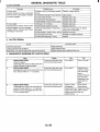
1. General Description
A: SPECIFICATIONS
I
I
Item
I Vibration torque of rod against lever
N.m (kgf-m, ft-lb)
I
cs-2
Specification
0.7 (0.07, 0.5) or less
-1
I
GENERAL DESCRIPTION
CONTROL SYSTEMS
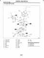
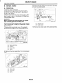
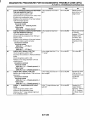
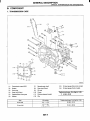
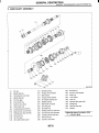
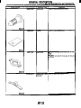
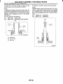
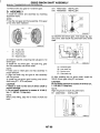
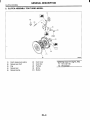
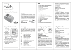
B: COMPONENT
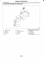
1. AT SELECT LEVER
.‘
.
‘‘
.‘
.‘ ‘-A
I
I
‘
TR054t
Indicator light bulb
Detent arm
Detent spring
Select lever
Spring pin
Arm
Pin
Plate
Grommet
Packing
Grip
Indicator cover
Cushion
Guide plate
Snap pin
Outer cable
Inner cable
Nut B
Nut A
Clip
Lock plate
Shift lock solenoid
Clamp
Cover
cs-3
(25) Slider
(26) Clip
(27) “P” position switch
(28) Spring
(29) Button
Tightening torque: N.m (kgf-m, fi-lb)
T1: 7.5 (0.76, 5.5)
T2: 13 (1.3, 9.4)
T3: l S ( 1 . 8 , 13.0)
T4: 33 (3.4,25)
I
GENERAL DESCRIPTION
CONTROL SYSTEMS
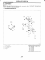
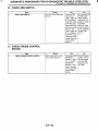
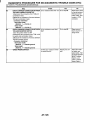
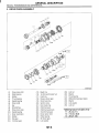
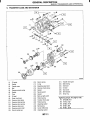
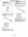
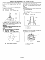
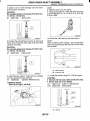
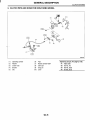
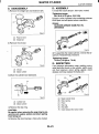
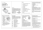
2. MT GEAR SHIFT LEVER
TI30594
(1)
(2)
(3)
(4)
(5)
(6)
(7)
(8)
(9)
Gear shift knob
Console boot
Plate complete
Lever
Bush
Bush
Locking wire
Boot
Snap ring
(IO) O-ring A
(11) O-ring B
(12) BushA
(13) Cushion rubber
(14) Bush6
(15 ) Joint
(16) Rod
(17) Bracket
(18) Washer
cs-4
(19)
(20)
Stay
Spacer
Tightening torque: N-m (kgf-m, ft-lb)
T1: 7.5 (0.76, 5.5)
T2: 12 (1.2, 8.7)
T3: lS(1.8, 13.0)
I
GENERAL DESCRIPTION
CONTROL SYSTEMS
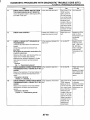
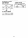
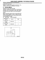
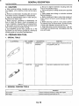
C: CAUTION
Wear working clothing, including a cap, protective goggles, and protective shoes during operation.
Remove contamination including dirt and corrosion before removal, installation or disassembly.
Keep the disassembled parts in order and protect them from dust or dirt.
Before removal, installation or disassembly, be
sure to clarify the failure. Avoid unnecessary removal, installation, disassembly, and replacement.
Use SUBARU genuine grease etc. or the equivalent. Do not mix grease etc. with that of another
grade or from other manufacturers.
Be sure to tighten fasteners including bolts and
nuts to the specified torque.
Place shop jacks or safety stands at the specified
points.
Apply grease onto sliding or revolution surfaces
before installation.
Before installing O-rings or snap rings, apply sufficient amount of grease to avoid damage and deformation.
Before securing a part on a vice, place cushioning material such as wood blocks, aluminum plate,
or shop cloth between the part and the vice.
Before disconnecting electrical connectors, be
sure to disconnect the negative terminal from battery.
c
.
cs-5
I
ELECTRICAL COMPONENT
CONTROL SYSTEMS
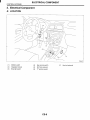
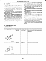
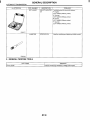
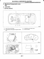
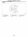
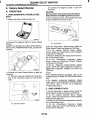
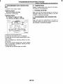
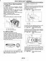
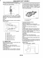
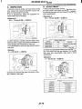
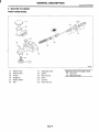
2. Electrical Component
A: LOCATION
(1)
(2)
(3)
Inhibitor switch
Integrated module
Stop light switch
(4)
(5)
(6)
Key warning switch
Shift lock solenoid
“P” position switch
CS-6
(7)
Key lock solenoid
ELECTRICAL COMPONENT
I
CONTROL SYSTEMS
(2)
\ \o\
'
TR0548
B2M2246E
TR0549
cs-7
I
AT SHIFT LOCK SYSTEM
CONTROL SYSTEMS
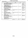
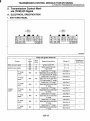
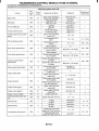
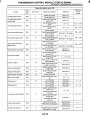
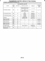
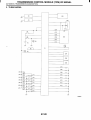
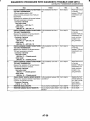
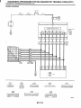
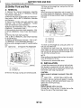
3. AT Shift Lock System
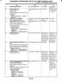
A: ELECTRICAL SPECIFICATION
10 9
16 15 14 13 12 11 10 9
8
7
6
5
4
3
2
1
20 19 18 17 16 15 14 13 12 11
BO031 1
I
Contents
Connector No.
Terminal No.
Battery power supply
Ignition power supply
Ignition power supply
8281
B280
8280
2
19
10
Inhibitor Switch (“P” position)
8280
5
Stop light switch
I
“P” position switch
Shift lock solenoid signal
I
I
B280
I
9
B280
8281
9
InpuVOutput signal
Measured value and measuring conditions
9-16V
10 - 15 V when ignition switch is at ON or START.
10 - 15 V when ignition switch is at ACC.
0 V when select lever is in “ P position.
9 - 16 V when select lever is in other positions than “ P
oosition.
9 - 16 V when stop light switch is ON.
0 V when stop light switch is OFF.
0 V when select lever is in “ P position.
9 - 16 V when select lever is in other positions than “P”
position.
8.5 - 16 V when shift lock is released.
0 V when shift lock is oPeratina.
9 - 16 V when key is inserted.
0 V when key is removed.
7.5 - 16 V when turning ignition switch to ON, select
lever is in “P” position and brake switch is ON.
0 V at other conditions than above.
.
I
Key warning switch signal
6280
20
Key lock solenoid signal
8281
3
Ground
Ground
B281
B281
4
13
CS-8
-
I
AT SHIFT LOCK SYSTEM
CONTROL SYSTEMS
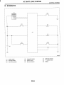
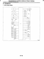
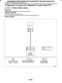
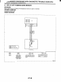
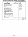
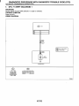
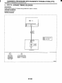
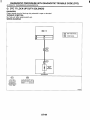
B: SCHEMATIC
OQ
(2)
0
0
L
c----
(4)
(1)
(2)
Ignition switch
Stop light switch
(3)
Key warning switch
(4)
(5)
(6)
integrated module
Inhibitor switch
Key lock solenoid
cs-9
(7)
(8)
(9)
Shift lock solenoid
“P” position switch
Battery
AT SHIFT LOCK SYSTEM
CONTROL SYSTEMS
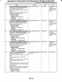
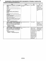
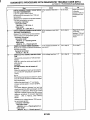
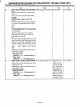
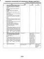
C: INSPECTION
Step
CHECK SHIFT LOCK.
1)Turn the ignition switch ON.
2)Move the select lever to “P” position.
!
CHECK SHIFT LOCK.
I
CHECK KEY INTERLOCK.
Check
While brake pedal is
depressed, can select lever
move from “ P range to other
positions?
Yes
Go to step 2.
NO
Inspect “SELECT
LEVER CANNOT
BE SHIFT
LOCKED. <Ref.
to CS-I4, SELECT
LEVER CANNOT
BE SHIFT
LOCKED,
INSPECTION, AT
Shift Lock System.>
While brake pedal is not
Inspect “SELECT Go to step 3.
depressed, can select lever
LEVER SHIFT
move from “P” range to other LOCK CANNOT
positions?
BE RELEASED.
<Ref. to CS-16,
SELECT LEVER
SHIFT LOCK
CANNOT BE
RELEASED,
INSPECTION, AT
Shift Lock System.>
4T shift lock sysInspect “KEY
When select lever is in other
than “P” position, does ignition INTERLOCK
em is normal.
switch turn to “LOCK position? DOES NOT BE
Or when select lever is in “ P LOCKED OR
position, does ignition switch RELEASED. <Ref.
turn to “LOCK position?
to CS-20, KEY
INTERLOCK
DOES NOT LOCK
OR RELEASE,
INSPECTION, AT
Shift Lock System.>
cs-10
AT SHIFT LOCK SYSTEM
CONTROL SYSTEMS
cs-11
CONTROL SYSTEMS
AT SHIFT LOCK SYSTEM
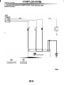
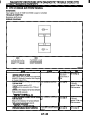
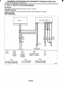
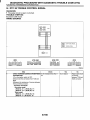
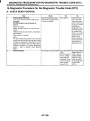
1. INTEGRATED MODULE POWER SUPPLY AND GROUND LINE
WIRING DIAGRAM:
r
0
P
0
z
I
A:
@
I I
-
TR0551
cs-12
1
AT SHIFT LOCK SYSTEM
CONTROL SYSTEMS
~
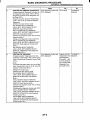
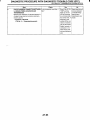
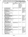
Step
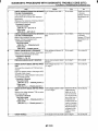
CHECK FUSE (No. 3 , 4 and 11).
1)Aemove the fuse (No. 3 , 4 and 11).
!
Check
s the fuse (No. 3,4 or 11)
)lawn out?
CHECK HARNESS CONNECTOR BETWEEN s the resistance less than 1
2?
INTEGRATED MODULE AND BODY
GROUND.
1)Turn the ignition switch to OFF.
2)Measure the resistance of harness between
integrated module and chassis ground.
Connector & terminal
(8281) No. 4 - Chassis ground:
(8281) No. 13 Chassis ground:
s the voltage more than 9 V?
CHECK BATTERY POWER SUPPLY.
1)Turn the ignition switch to ON (engine OFF).
2)Measure the voltages between integrated
module and chassis ground.
Connector & terminal
(8281) No. 1 (+)
Chassis ground (-):
No
Yes
3eplace the fuse So to step 2.
:No. 3, 4 or 11). If
he replaced fuse
:No. 3,4 or 11)
ias blown out eas
ly, repair short cir:uit in harness
letween fuse and
ntegrated module.
Repair open circuit
30 to step 3.
in harness
between integrated module and
body ground.
-
I
30 to step 4.
-
I
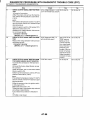
>
s the voltage more than 9 V?
CHECK IGNITION POWER SUPPLY CIRCUIT.
1)Tufn the ignition switch to ACC.
2)Measure the voltage between integrated
module and chassis ground.
Connector & terminal
(8280) No. 10 (+) - Chassis ground (-):
s the voltage more than 9 V?
CHECK IGNITION POWER SUPPLY CIRCUIT.
1)Turn the ignition switch to ON (engine OFF).
2)Measure the voltage between integrated
module and chassis ground.
Connector & terminal
(8281) No. 19 (+)
Chassis ground (-):
s there poor contact in power
CHECK POOR CONTACT.
;upply and ground line circuit?
So to step 5.
Go to step 6.
-
i
CS-13
Repair poor contact.
Repair open circuit
harness between
battery and integrated module,
and poor contact
in coupling connector.
Repair open circuit
harness between
battery and integrated module,
and poor contact
in coupling connector.
Repair open circuit
harness between
battery and integrated module,
and poor contact
in coupling connector.
Replace the integrated module.
AT SHIFT LOCK SYSTEM
CONTROL SYSTEMS
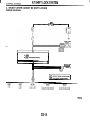
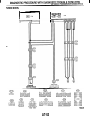
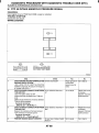
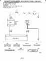
2. SELECT LEVER CANNOT BE SHIFT LOCKED
WIRING DIAGRAM:
SBF-1
STOP LIGHT
@
B: @ INTEGRATED MODULE
A:
I
1I
la1
I
I
SHIFT LOCK
SOLENOID
I
I
s
OC :WITHOUT CRUISE CONTROL MODEL
WC :WITH CRUISE CONTROL MODEL
TR0552
cs-14
AT SHIFT LOCK SYSTEM
CONTROL SYSTEMS
I
2
3
4
5
6
7
8
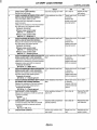
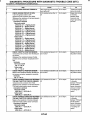
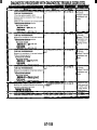
Step
CHECK STOP LIGHT SWITCH.
Depress the brake pedal.
CHECK HARNESS BETWEEN STOP LIGHT
SWITCH AND INTEGRATED MODULE.
1)Turn the ignition switch to OFF.
2)Disconnect the integrated and stoplight
switch connector.
3)Measure the resistance of harness between
stop light switch and integrated module.
Connector & terminal
Without cruise control model
(864) NO. 1 - (B280) NO. 9:
Without cruise control model
(B65) NO. 3 - (8280) NO. 9:
CHECK HARNESS BETWEEN STOP LIGHT
SWITCH AND INTEGRATED MODULE.
Measure the resistance of harness between
stop light switch and chassis ground.
Connector & terminal
Without cruise control model
(B64) No. 1 - Chassis ground:
Without cruise control model
(B65) No. 3 - Chassis ground:
CHECK HARNESS BETWEENINTEGRATED
MODULE AND SHIFT LOCK SOLENOID.
1)Disconnect the shift lock solenoid connector
2)Measure the resistance of harness between
integrated module and shift lock solenoid..
Connector & terminal
(B116) NO. 4 - (8281) NO. 9:
CHECK HARNESSBETWEENINTEGRATED
MODULE AND SHIFT LOCK SOLENOID.
Measure the resistance of harness between
shift lock solenoid and chassis ground.
Connector & terminal
( B l l 6 ) No. 4 - Chassis ground:
CHECK HARNESS BETWEEN SHIFT LOCK
SOLENOID AND CHASSIS GROUND.
Measure the resistance of harness between
shift lock solenoid and chassis ground.
Connector & terminal
(6116) No. 5 - Chassis ground:
CHECK SHIFT LOCK SOLENOID.
Measure the resistance of shift lock solenoid
connector terminals.
Terminal
NO. 4 -NO. 5:
CHECK SHIFT LOCK SOLENOID.
Connect the battery with shift lock solenoid
connector terminal and operate solenoid.
Terminal
NO. 4 (+) NO. 5 (--)I
CHECK POOR CONTACT.
Check
Does the stop light turn ON?
Is the resistance more than 1
MR?
Is the resistance less than 1
n?
Yes
Go to step 2.
No
Inspect the stop
light system.
Repair open circuit So to step 3.
in harness
between integrated module and
stop light switch.
Repair short circuit Go to step 4.
in harness
between integrated module and
stop light switch.
Is the resistance more than 1
MR?
Repair open circuit Go to step 5.
in harness
between integrated module and
shift lock solenoid.
Is the resistance less than 1
Q?
Repair short circuit Go to step 6.
in harness
between integrated module and
shift lock solenoid.
Is the resistance more than 1
MR?
Repair open circuit Go to step 7.
in harness
between shift lock
solenoid and body
ground.
Is the resistance between 10
and 20 R?
Go to step 8.
Replace the shift
lock solenoid.
Does the shift lock solenoid
operate properly?
Go to step 9.
Replace the shift
lock solenoid.
Is there poor contact in key
lock circuit?
Repair poor contact.
Replace the integrated module.
-
9
CS-15
AT SHIFT LOCK SYSTEM
CONTROL SYSTEMS
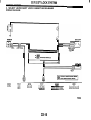
3. SELECT LEVER SHIFT LOCK CANNOT BE RELEASED
WIRING DIAGRAM:
INHIBITOR
SWITCH
STOP LIGHT
SWITCH
I
@
B: @ INTEGRATED MODULE
A:
I
SHIFT LOCK
SOLENOID
~
I
I
B
m
n
9 10 11 12
11213]4]516171819110
11~12~13~14]15]16~17~18~19~20
TR0553
CS-16
I
AT SHIFT LOCK SYSTEM
CONTROL SYSTEMS
~
~
Check
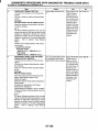
Step
;ombination
meter indicator
CHECK INHIBITOR SWITCH.
1)Turn the ignition switch to ON (engine OFF). amp and select lever “ P , “R”,
2)Move the select lever from “P”to “1” range. IN”, “ 3 , “ 2 and “1” are cor.ectly matched?
s the resistance less than 1
CHECK HARNESS BETWEEN INHIBITOR
n?
SWITCH AND INTEGRATED MODULE.
1)Turn the ignition switch to OFF.
2)Disconnect the connector transmission harness and intgrated module.
3)Measure the resistance of harness between
integrated module and chassis ground.
Connector & terminal
(6280) No. 5 - Chassis ground:
s the resistance more than 1
CHECK HARNESS BETWEEN INHIBITOR
WR?
SWITCH AND INTEGRATED MODULE.
Measure the resistance of harness between
integrated module and inhibitor switch.
Connector & terminal
(612) NO. 3 - (6280) NO. 5:
s the resistance less than 1
CHECK HARNESS BETWEEN INHIBITOR
n?
SWITCH AND CHASSIS GROUND.
Measure the resistance of harness between
integrated module and chassis ground.
Connector & terminal
(612) No. 4
Chassis ground:
s the resistance more than 1
CHECK INHIBITOR SWITCH.
wn?
1)Move the select lever to “ P position.
2)Measure the resistance of transmission harness connector terminals.
Connector & terminal
(T3) NO. 3 - NO. 4:
CHECK OUTPUT SIGNAL FOR INTEGRAT- Is the voltage between 9 and
16 V?
ED MODULE.
1)Connect all connectors.
2)Turn the ignition switch to ON.
3)Measure the voltage between integrated
module and chassis ground.
Connector & terminal
(6280) No. 5 (+) - Chassis ground (-):
Does the stop light turn on?
CHECK STOP LIGHT SWITCH.
Depress the brake pedal.
CHECK HARNESS BETWEEN STOP LIGHT Is the voltage more than 9 V?
SWITCH AND AT SHIFT LOCK CONTROL
MODULE.
1)Depress the brake pedal.
2)Measure the voltage between integrated
module and chassis ground.
Connector & terminal
(6280) No. 9 (+) - Chassis ground (-):
CHECK HARNESS BETWEENINTEGRATED Is the resistance more than 1
MR?
MODULE AND SHIFT LOCK SOLENOID.
1)Turn the ignition switch to OFF.
2)Disconnect the connector from shift lock
solenoid and integrated module.
3)Measure the resistance of harness between
integrated module and shift lock solenoid.
Connector & terminal
(6281) NO. 9 - (61161 NO. 4:
-
CS-17
Yes
Go to step 2.
No
4djust inhibitor
;witch and select
:able.
Repair short circuit 30 to step 3.
in harness
between integrated module and
transmission connector.
Repair open circuit 30 to step 4.
in harness
between integrated module and
transmission connector
Sepair open circuii
Go to step 5.
n harness
2etween inteJrated module and
:hassis ground.
Repair or replace
inhibitor switch.
30 to step 6.
Go to step 7.
30 to step 15.
Go to step 8.
Inspect stop light
iystem.
Repair open or
short circuit in har,
ness between inte
grated module ana
itop light switch.
Go to step 9.
Repair open circuit Go to step 10.
in harness
between integrated module and
shift lock solenoid.
I
AT SHIFT LOCK SYSTEM
CONTROL SYSTEMS
IO
I1
12
13
-...
14
5
.
Step
CHECK HARNESS BETWEENINTEGRATEC
MODULE AND SHIFT LOCK SOLENOID.
Measure the resistance of harness between
shift lock solenoid and chassis ground.
Connector & terminal
(6281) No. 9 - Chassis ground:
CHECK HARNESS BETWEEN SHIFT LOCK
SOLENOID AND CHASSIS GROUND.
Measure the resistance of harness between
shift lock solenoid and chassis ground.
Connector & terminal
( 6 1 16) No. 5 - Chassis ground:
CHECK SHIFT LOCK SOLENOID.
Measure the resistance of shift lock solenoid
connector terminals.
Terminal
NO. 4 - NO. 5:
CHECK SHIFT LOCK SOLENOID.
Connect the battery with shift lock solenoid
connector terminal and operate solenoid.
Terminal
NO. 4 (+) - NO. 5I)-(
CHECK OUTPUT SIGNAL FOR AT SHIFT
LOCK CONTROL MODULE.
1)Turnthe ignition switch to ON (engine OFF).
2)Measure the voltage between integrated
module and chassis ground.
Connector & terminal
(6281) No. 9 (+) - Chassis groundI)-(
CHECK POOR CONTACT.
Check
Is the resistance less than 10
R?
Yes
Go to step 11.
No
Repair short circui
in harness
between integrated module an(
shift lock solenoid
Is the resistance less than 1
Go to step 12.
Repair open circui
in harness
between shift lock
solenoid and chas
sis ground.
Go to step 13.
Replace the shift
lock solenoid.
Is shift lock solenoid operating So to step 14.
properly?
Replace the shift
lock solenoid.
Is the voltage more than 8.5 V? 30 to step 15.
Replace the integrated module.
Is there poor contact in key
lock circuit?
Replace the integrated module.
n?
Is the resistance between 10
and 20 R?
CS-18
3epair poor conact.
I
AT SHIFT LOCK SYSTEM
CONTROL SYSTEMS
cs-19
AT SHIFT LOCK SYSTEM
CONTROL SYSTEMS
4. KEY INTERLOCK DOES NOT LOCK OR RELEASE
WIRING DIAGRAM:
>
a
(D
E
si
$ 0
c.
TR0554
cs-20
I
I
AT SHIFT LOCK SYSTEM
CONTROL SYSTEMS
Yes
No
3epair open or
short circuit in harless between bat:ery and key
Narning switch.
Step
CHECK HARNESS BETWEEN BATTERY
AND KEY WARNING SWITCH.
1)Disconnectthe connector key warning
switch.
2)Measure the voltage of harness between key
warning switch and chassis ground.
Connector & terminal
(874) No. 2 - Chassis ground:
CHECK KEY WARNING SWITCH.
Measure the resistance of stop light switch
connector terminals.
Terminal
NO. 1 - NO. 2:
CHECK KEY WARNING SWITCH.
1)Remove the key.
2)Measure the resistance of stop light switch
connector terminals.
Terminal
Check
s the voltage between 9 and
I6 V?
Is the resistance more than 1
MR?
30 to step 4.
Replace key warning switch.
CHECK HARNESS BETWEEN AT SHIFT
LOCK CONTROL MODULE AND KEY
WARNING SWITCH.
1)Disconnectthe integrated module connector.
2)Measure the voltage of harness integrated
module and chassis ground.
Connector & terminal
(8280) No. 20 - Chassis ground:
CHECK HARNESS BETWEENINTEGRATED
MODULE AND KEY LOCK SOLENOID.
1)Disconnectthe connector key lock solenoid.
2)Measure the resistance of harness between
integrated module and key lock solenoid.
Connector & terminal
(873) NO. 2 - (8281) NO. 3:
CHECK HARNESS BETWEEN INTEGRATED
MODULE AND KEY LOCK SOLENOID.
Measure the resistance of harness between
integrated module and chassis ground.
Connector & terminal
(B281) No. 3 - Chassis ground:
CHECK HARNESS BETWEEN KEY LOCK
SOLENOID AND CHASSIS GROUND.
Measure the resistance of harness between
key lock solenoid and chassis ground.
Connector & terminal
(873) No. 1 - Chassis ground:
CHECK KEY LOCK SOLENOID.
Measure the resistance of key lock solenoid
connector terminals.
Connector & terminal
(873) NO. 1 -NO. 2:
CHECK HARNESS BETWEEN “P” POSITION SWITCH AND CHASSIS GROUND.
Measure the resistance of harness between
“ P position switch and chassis ground.
Connector & terminal
(8116) No. 2 - Chassis ground:
Is the resistance more than 9
V?
30 to step 5.
Repair open circuit
in harness
between integrated module and
key warning
switch.
Is the resistance more than 1
MR?
Repair open circuit Go to step 6.
n harness
setween integrated module and
cey lock solenoid.
Is the resistance more than 1
R?
Go to step 7.
Repair short circuit
in harness
between integrated module and
key lock solenoid.
Is the resistance less than 10
Go to step 8.
Repair open circuit
in harness
between key lock
solenoid and chas
sis ground.
Is the resistance between 4
and 8 R?
Go to step 14.
Replace the key
lock solenoid.
Is the resistance less than 1
R?
Go to step 10.
Repair short circuil
in harness
between “P” position switch and
integrated module
Is the resistance more than 1
WR?
30 to step 2.
3eplace key warn- 30 to step 4.
ng switch.
NO. 1 - NO. 2:
a?
cs-21
AT SHIFT LOCK SYSTEM
CONTROL SYSTEMS
Step
IO
I1
I2
k
4
I5
.
CHECK HARNESS BETWEEN AT SHIFT
LOCK CONTROL MODULE AND “P” POSITION SWITCH.
1)Disconnectthe connector from “ P position
switch.
2)Measure the resistance of harness between
integrated module and “ P position switch.
Connector & terminal
(B116) NO. 2 - (8280) NO. 6:
CHECK HARNESS BETWEEN “P” POSITlON SWITCH AND CHASSIS GROUND.
Measure the resistance of harness “P”position
switch and chassis ground.
Connector & terminal
( B l l 6 ) No. 6 - Chassis ground:
CHECK “P” POSITION SWITCH.
1)Move the select lever to “P” position.
2)Measure resistance between “ P position
switch connector terminals.
Terminal
NO. 2 - NO. 6:
CHECK “P” POSITION SWITCH.
1)Move the select lever to other than “P” position.
2)Measure resistance between “ P position
switch connector terminals.
Terminal
NO. 2 - NO. 6:
CHECK OUTPUT SIGNAL FOR INTEGRATED MODULE.
1)Connect all connectors.
2)Turn the ignition switch to ON (engine OFF).
3)Move the select lever to “P” position.
4)Press the brake pedal.
5)Measure the voltage between integrated
module connector and chassis ground.
Connector & terminal
(8281) No. 3 (+) - Chassis ground (-):
CHECK POOR CONTACT.
Check
s the resistance more than 1
AQ?
No
Yes
Repair open circuit Go to step 11.
in harness
between integrated module and
“P” position switch.
s the resistance more than 1 IGo to step 12.
JIR?
Repair open circuit
in harness
between “P” position switch and
shassis ground.
s the resistance less than 1
2?
Go to step 13.
Replace the “P”
aosition switch.
s the resistance more than 1
JIQ?
Go to step 14.
Replace the “P”
position switch.
s the voltage 7.5 and 16 V?
30 to step 15.
Replace the integrated module.
s there poor contact in AT shift Repair poor conx k circuit?
tact.
cs-22
Replace the integrated module.
I
SELECT LEVER
CONTROL SYSTEMS
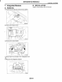
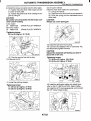
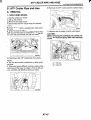
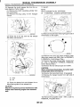
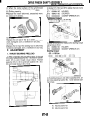
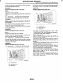
4. Select Lever
B: INSTALLATION
A: REMOVAL
1) Mount the select lever onto the vehicle body.
2) Tighten the four bolts to install the select lever to
the vehicle body, then connect the connector.
1) Set the vehicle on the lift.
2) Disconnect the ground terminal from battery.
3) Move the select lever to the “N” position.
4) Lift-up the vehicle.
5) Remove the rear exhaust pipe and muffler.
6) Remove the heat shield cover. (If equipped)
7) Disconnect the cable from select lever and then
remove the cable bracket.
(A) Adjusting nuts
(B) Cable bracket
8) Lower the vehicle.
9) Remove the console box. <Ref. to El-41, REMOVAL, Console Box.>
10) Disconnect the connectors, then remove the
four bolts to take out the select lever assembly from
the body.
I1510
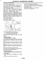
Tightening torque:
13 N.m (1.3 kgf-m, 9.4 ft-lb)
3) Install the console box. <Ref. to El-39, INSTALLATION, Glove Box.>
4) Set the location of select lever at ‘IN” position.
5) Lift-up the vehicle.
6) Set the location of range select lever to “N” position.
7) Insert the thread portion of the other inner cable
and into the connector hole of the select lever, and
fix the other outer cable end to the bracket.
8) Adjust the select cable position. <Ref. to CS-27,
ADJUSTMENT, Select Cable.>
9) After completion of fitting, make sure that the select lever operates smoothly all across the operating range.
10) Inspect the following items. If the following inspection reveals problems, adjust the select cable
and inhibitor switch. <Ref. to CS-27, ADJUSTMENT, Select Cable.> and <Ref. to AT-28, ADJUSTMENT, Inhibitor Switch.>
(1) The engine starts operating when select lever is in position “P”,but not in other positions.
(2) The back-up light is lit when the select lever
is in position ‘W, but not in other positions.
(3) Select lever and indicator positions are
matched.
11) Check the shift-lock system.
(1) Ensure the ignition switch rotates from
“ACC” to “LOCK when the select lever is set at
“P”. Also check that ignition key can be removed
only from the “LOCK position.
(2) Ensure the select lever moves from “P” to
any other position when the brake pedal is depressed with ignition key set at “ON” or
“START.
12) Install heat shield cover. (If equipped)
13) Install rear exhaust pipe and muffler.
CS-23
I
SELECT LEVER
CONTROL SYSTEMS
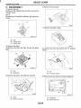
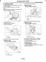
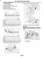
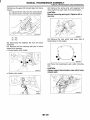
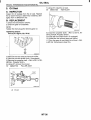
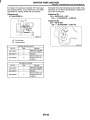
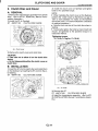
C: DISASSEMBLY
6) Remove the lock plate.
1) Remove the grip.
2) Remove the indicator light and then remove the
indicator cover.
NOTE:
Be careful not to break the indicator light during removal.
n
v
TR0556
7) Remove the pattern plate.
B3M1511A
c.
(A) Grip
(B) Indicator cover
(C) indicator light
~
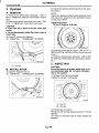
3) Remove the slider.
4) Remove the clips and then remove the guide
plate.
TR0557
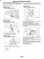
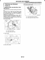
8) Remove the clip and remove the “P” position
switch.
I
I
B3M2177A
(A) Clips
(B) Guide plate
(A) Clip
(B) “P” position switch
5) Remove the clamp, and shift lock solenoid.
I
9) Remove the cap and then extract straight pin.
TR0555
B3M1797A
(A) Clamp
(B) Shift lock solenoid
(A) Straight pin
(B) Select lever lower
CS-24
I
SELECT LEVER
CONTROL SYSTEMS
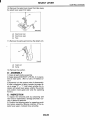
10)Remove the select lever lower then take away
the select lever upper from plate.
dA’
B3M1848A
(A)
Select lever lower
(B) Select lever upper
(C) Plate
1 1 ) Remove the spring and remove the detent arm.
(A)
Detent arm
(B) Spring
12)Remove the cushion.
D: ASSEMBLY
1) Clean all parts before assembly.
2) Apply grease [NIGTIGHT LYW No. 2 or equivalent] to each parts. <Ref. to CS-3, AT Select Lever.>
3) Assembly is in the reverse order of disassembly.
4) After completion of fitting, transfer the select lever to range “P” - “l”, then check whether the indicator and select lever agree, whether the pointer
and position mark agree and what the operating
force is.
E: INSPECTION
1) Inspect the removed parts by comparing with
new ones for deformation, damage and wear. Correct or replace if defective.
2) Confirm the following parts for operating condition before assembly. Moving condition of the selector lever upper, it should move smoothly.
CS-25
I
SELECT CABLE
CONTROL SYSTEMS
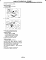
10) Disconnect the cable from select lever and then
remove the cable bracket.
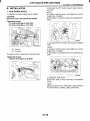
5. Select Cable
A: REMOVAL
1) Set the vehicle on the lift.
2) Disconnect the ground terminal from battery.
3) Prior to removal, set the lever to “N” position.
4) Lift-up the vehicle.
5) Remove the front and center exhaust pipe. (Nonturbo model) <Ref. to EX(S0HC)-5, REMOVAL,
Front Exhaust Pipe.>
CAUTION:
When removing the exhaust pipes, be careful
each exhaust pipe does not drop out.
6) Remove the center exhaust pipe. (Turbo model)
<Ref. to EX(D0HC TURBO)-8, REMOVAL, Center
Exhaust Pipe.>
7) Remove’ the heat shield cover. (If equipped)
8) Remove the snap pin from range select lever.
(A) Adjusting nuts
(B) Cable bracket
11) Remove the select cable from plate assembly.
(A) Range select lever
(B) Snap pin
(C) Select cable
(D) Clamp
9) Remove the plate assembly from transmission
case
(A) Select cable
(B) Plate ASSY
(C) Clamp
CS-26
I
I
I
SELECT CABLE
CONTROL SYSTEMS
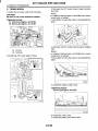
B: INSTALLATION
C: INSPECTION
1) Install the select cable to plate assembly.
Check the removed cable and replace if damaged,
rusty, or malfunctioning.
1) Check for smooth operation of the cable.
2) Check the inner cable for damage and rust.
3) Check the outer cable for damage, bends, and
cracks.
4) Check the boot for damage, cracks, and deterioration.
5) Move the select lever from “P” position to “1” position. You should be able to feel the detentes in
each position. If the detentes cannot be felt or the
position pointer is improperly aligned, adjust the cable.
Tightening torque:
32 N.m (3.3 kgf-m, 24 fi-lb)
2) Install the select cable to range select lever.
3) Install the plate assembly to transmission.
Tightening torque:
T: 24.5 N-m (2.5 kgf-m, 18.1 ft-lb)
D: ADJUSTMENT
1) Set the vehicle on the lift.
2) Disconnect the ground terminal from battery.
3) Set the lever to “N” position.
4) Lift-up the vehicle.
5) Remove the rear exhaust pipe and muffler.
6) Remove the heat shield cover. (If equipped)
7) Loosen the adjusting nut on each side.
c
.
(A) Select cable
(B) Plate ASSY
4) Install the snap pin to range select lever
I /
(A) Adjusting nut A
(B) Adjusting nut B
(A)
(B)
(C)
(D)
Range select lever
Snap pin
Select cable
Clamp
5) Move the select lever to the “N” position, then adjust the select cable position. <Ref. to CS-27, ADJUSTMENT, Select Cable.>
6) Install the heat shield cover. (If equipped)
7) Install the front and center exhaust pipe. (Nonturbo model) <Ref. to EX(S0HC)-6, INSTALLATION, Front Exhaust Pipe.>
8) Install the center exhaust pipe. (Turbo model)
<Ref. to EX(D0HC TURBO)-9, INSTALLATION,
Center Exhaust Pipe.>
CS-27
03M1792A
I
SELECT CABLE
CONTROL SYSTEMS
8) Turn the adjusting nut B until it lightly touches the
connector.
(A)
(B)
(C)
(D)
(E)
(F)
Front side
Select lever
Connector
Adjusting nut B
Contact point
Adjusting nut A
S).While preventing the adjusting nut B from moving with a wrench, tighten adjusting nut A.
Tightening torque:
7.5 N.m (0.76 kgf-m, 5.5 ft-lb)
(A) Adjusting nut A
(B) Adjusting nut B
10) After completion of fitting, make sure that the
select lever operates smoothly all across the operating range.
11) Install in the reverse order of removal.
CS-28
AT SHIFT LOCK SOLENOID AND “P” POSITION SWITCH
CONTROL SYSTEMS
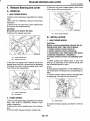
6. AT Shift Lock Solenoid and
“P” Position Switch
6 : INSTALLATION
Install in the reverse order of removal.
A: REMOVAL
1) Disconnect the ground terminal from battery.
2) Remove the console box. <Ref. to El-41, REMOVAL, Console Box.>
3) Disconnect the connector.
4) Remove the grip.
5 ) Remove the indicator cover.
6) Remove the slider.
7) Remove the cushion.
8) Remove the clip and remove the “P” position
switch.
(A) Clip
(B) “ P position switch
9) Remove the clamp and remove the shift lock solenoid.
(A) Clamp
(B) Shift lock solenoid
CS-29
I
I
AT SHIFT LOCK SOLENOID AND “P” POSITION SWITCH
CONTROL SYSTEMS
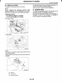
C: INSPECTION
1
2
3
4
Step
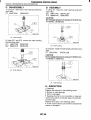
CHECK SHIFT LOCK SOLENOID.
Measure the resistance of shift lock solenoid
connector terminals.
Terminal
NO. 4 - NO. 5
CHECK SHIFT LOCK SOLENOID.
Connect the battery with shift lock solenoid
connector terminal, operate solenoid.
Terminal
NO. 4 (+) - NO. 5 (-)
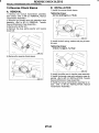
CHECK “P” POSITION SWITCH.
1)Move the select lever to “ Pposition.
2)Measure resistance between “ P position
switch connector terminals.
CHECK “P” POSITION SWITCH.
1)Move the select lever to other than “P” position.
2)Measure resistance between “P” position
switch connector terminals.
Check
and 20 R?
lock solenoid and
“ P position switch
assembly.
Is the shift lock solenoid oper- Go to step 3.
ating properly?
Replace the shift
lock solenoid and
“ P position switch
assembly.
Is the resistance less than 1
Go to step 4.
Replace the “ P
position switch.
Normal
Replace the “P”
position switch.
n?
Is the resistance more than 1
MR?
CS-30
INTEGRATED MODULE
I
CONTROL SYSTEMS
B: INSTALLATION
7. Integrated Module
Install in the reverse order of removal.
A: REMOVAL
1 ) Disconnect the ground terminal from battery.
2 ) Remove the lower cover.
3) Remove the knee bolster.
4) Disconnect the connector from integrated module.
5) Remove the integrated module.
CS-31
I
MT GEAR SHIFT LEVER
CONTROL SYSTEMS
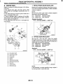
8. MT Gear Shift Lever
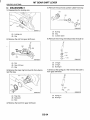
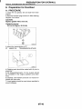
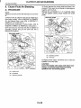
11) Remove the cushion rubber from body.
A: REMOVAL
1) Set the vehicle on the lift.
2) Remove the gear shift knob.
3) Disconnect the ground terminal from battery.
4) Remove the console box. <Ref. to El-41, REMOVAL, Console Box.>
5) Remove the boot plate from body.
(A) Stay
(B) Cushion rubber
12) Remove the joint and then extract the spring
pin.
@.Lift-up the vehicle.
7) Remove the rear exhaust pipe and muffler.
8) Remove the heat shield cover. (If equipped)
9) Remove the stay from transmission bracket.
(A) Joint
(B) Spring pin
13) Lower the vehicle.
14) Remove the gear shift lever
(A) Stay
(B) Transmission bracket
10) Remove the rod from joint.
CS-32
I
I
MT GEAR SHIFT LEVER
CONTROL SYSTEMS
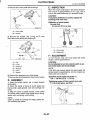
B: INSTALLATION
7) Connect the rod to the joint.
1) Install the joint to the transmission and secure
with the straight pin.
2) Insert the gear shift lever from room side.
NOTE:
After inserting the rod and stay, temporarily put
them onto transmission mount.
Tightening torque:
18 N.m (1.8 kgf-m, 73.0 ff-lb)
(A) Stay
(B) Rod
8) Connect the stay to transmission bracket.
3) Lift-up the vehicle.
4) Install the joint to shifter arm.
5) Insert the spring pin.
c
.
Tightening torque:
18 N-m (1.8 kgf-m, 13.0 ff-lb)
(A) Stay
(B) Transmission bracket
(A) Joint
(B) Spring pin
6) Mount the cushion rubber on the body.
Tightening torque:
18 N-m (1.8 kgf-m, 13.0 ff-lb)
9) Install the heat shield cover. (If equipped)
IO) Install the rear exhaust pipe and muffler.
1 1 ) Lower the vehicle.
12) Install the boot plate to body.
Tightening torque:
7.5 N.m (0.76 kgf-m, 5.5 ff-lb)
13) Install the consol box. <Ref. to El-41, INSTALLATION, Console Box.>
(A) Stay
(B) Cushion rubber
cs-33
I
I
MT GEAR SHIFT LEVER
CONTROL SYSTEMS
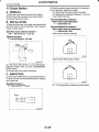
C: DISASSEMBLY
5) Remove the bush and cushion rubber from stay.
1) Disassemble the locking wire.
B3M08300
' ' B3M0617C
(A) Bushing
(B) Stay
(C) Cushion rubber
(A) Locking wire
(B) Stay
6) Remove the O-ring, then disconnect the bush D.
2) Remove the rod from gear shift lever.
-
B3M1828A
(A) O-ring B
(B) O-ring A
(C) Bushing B
(A) Rod
(B) Gear shift lever
(C) Stay
3) Remove the snap ring from bush B, then disconnect the stay.
7) Draw out the spring pin, then remove the bush C
from gear shift lever.
83M0621B
B3M0619B
(A) Spring pin
(B) BushingA
(A) Snap ring
(B) Bushing B
(C) Boot
4) Remove the boot from gear shift lever.
cs-34
I
MT GEAR SHIFT LEVER
CONTROL SYSTEMS
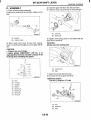
D: ASSEMBLY
1) Clean all parts before assembly.
2) Mount the bushing B and cushion rubber on the
stay.
4) Insert the gear shift lever into the boot hole.
5) Install the snap ring and stay to the bushing B.
B3M0619C
(A) Snap ring
(6) Bushing B
B3M0830C
(A) Bushing
(6) Cushion rubber
6) Tighten with locking wire to the extent that the
boot will not come off.
3) Mount each part; boot, O-ring, bush, spacer,
bush A, bush B and straight pin on the gear shift lever.
..-
CAUTION:
Always use new locking wire.
CAUTION:
Always use new O-rings.
Apply grease [DNIGTIGHT LYW No. 2 or
equivalent] to the inner and side surfaces of the
bushing when installing the spacer.
L
(A)
(6)
(C)
(D)
(E)
(F)
(G)
(H)
Boot
O-ring B
Bushing
Spacer
BushingA
Bushing E3
Spring pin
O-ring A
(A) Locking wire
(6) Stay
B3M0623C
7) Insert the rod into the boot hole.
8) Connect the rod to gear shift lever.
Tightening torque:
11.8 N.m (1.2 kgf-m, 8.7 fi-lb)
n
(A) Rod
(6) Shift lever
(C) Stay
cs-35
I
MT GEAR SHIFT LEVER
CONTROL SYSTEMS
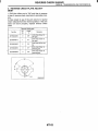
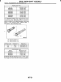
9) Check the swing torque of the rod in relation to
the gear shift lever.
If the torque exceeds the specification, replace the
bushing or retighten nuts.
Rocking torque:
0.7 N.m (0.07 kgf-m, 0.5 ft-lb) or less
E: INSPECTION
1) Check each part (bushing, cushion rubber, spacer, boot, stay and rod, etc.) for deformation, damage and wear. Repair or replace any defective part.
Determine defective parts by comparing with new
parts.
(A) Center of rotation
(6) Swing torque
70) Check that there is no excessive play and that
parts move smoothly.
B3M7 765A
(A) Bushing
(6) Cushion rubber
(C) Spacer
(D) Boot
(E) Stay
(F) Rod
CS-36
3
MT GEAR SHIFT LEVER
CONTROL SYSTEMS
2) Check the swing torque of the rod in relation of
the gear shift lever.
If the torque exceeds the specification, replace the
bushing or retighten nuts.
Rocking torque:
0.7 N-m (0.07 kgf-m, 0.5 ff-lb) or less
n
(6)
B3M1829C
(A) Center of rotation
(B) Swing torque
cs-37
GENERAL DlAGOSTlC
CONTROL SYSTEMS
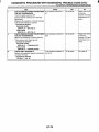
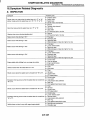
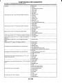
9. General Diagostic
A: INSPECTION
Problem Darts
Symptom
Shift lock does not function.
Shift lock cannot be released.
Key interlock does not function.
Key interlock cannot be released.
Starter does not run.
Back-up light does not light up.
Stop light switch
Shift lock solenoid
Integrated module
Stop light switch
Shift lock solenoid
Integrated module
Inhibitor switch
Key warning switch
“ P position switch
Key lock solenoid
Integrated module
Key warning switch
“ P position switch
Key lock solenoid
Integrated module
Inhibitor switch
Select cable
Starter circuit
Inhibitor switch
Select cable
Back-up light circuit
CS-38
I
AUTOMATIC TRANSMISSION
AT
Page
C.
.
1.
2.
3.
4.
5.
6.
7.
8.
9.
10.
11.
12.
13.
14.
15.
16.
17.
18.
19.
20 .
21.
General Description .................................................................................... 2
Automatic Transmission Fluid ..................................................................... 9
Differential Gear Oil ...................................................................................
11
Road Test .................................................................................................. 12
Stall Test ................................................................................................... 13
Time Lag Test ........................................................................................... 15
Line Pressure Test .................................................................................... 16
Transfer Clutch Pressure Test .................................................................. 18
Automatic Transmission Assembly ........................................................... 19
Transmission Mounting System ................................................................ 25
Extension Case Oil Seal ........................................................................... 27
Inhibitor Switch .......................................................................................... 28
Front Vehicle Speed Sensor ..................................................................... 32
Rear Vehicle Speed Sensor ......................................................................
35
Torque Converter Turbine Speed Sensor ................................................. 36
Control Vatve Body ................................................................................... 37
Shift Solenoids. Duty Solenoids and ATF Temperature Sensor ...............39
ATF Filter .................................................................................................. 44
Transmission Control Module (TCM) ........................................................ 45
Dropping Resistor .....................................................................................
46
ATF Cooler Pipe and Hose ....................................................................... 47
a
I
I
GENERAL DESCRIPTION
AUTOMATIC TRANSMISSION
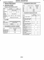
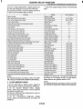
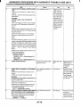
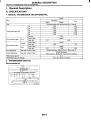
1. General Description
4. TRANSMISSION GEAR RATIO
A: SPECIFICATIONS
Model
1. TORQUE CONVERTER CLUTCH
Non-turbo
Turbo
Symmetric, 3 element, single stage, 2 phase
torwe converter
Model
Type
ratio torque
Nominal
diameter
speed
(at sea level)
One-way
clutch
1st
2nd
3rd
4th
I
1.9 - 2.1
I
I
1
1
Model
2,600 - 3,300 rpm
Sprague type one-way clutch
I
I
I
I
Except sedan
non-turbo
2.785
1.545
I
I
3.027
1.619
1.ooo
0.694
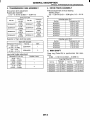
5. PLANETARY GEAR AND PLATE
2. OILPUMP
I Type
LDriving method
I
Sedan non-turbo
1.85-2.15
246 mm (9.69 in)
2,100 - 2,600 rpm
I
Pracoid constant-displacementpump
Driven by engine
9
Inner rotor
I
3. TRANSMISSION CONTROL ELEMENT
4-forward, 1-reverse, double-row planetary gears
Multi-Dlate clutch
3 sets
I Multi-plate brake I
2 sets
I
One-way clutch
1 sets
(sprague type)
Type
AT-2
1-1
Front sun gear number of
teeth
Front pinion number of teeth
Front internal gear number
of teeth
Rear sun gear number of
teeth
Rear pinion number of teeth
Drive & driven plate number
of high clutch
Drive & driven plate number
of low clutch
Drive & driven plate number
of 2-4 brake
Drive & driven plate number
of low & reverse brake
Turbo
I
“
1
33
I
21
75
42
37
I
I
19
I
17
4
5
6
7
1
I
I
I
I
GENERAL DESCRIPTION
Transmission in neutral, output member immov.
able, and engine start possible
Transmission in reverse for backing
(Reverse)
I
Liquid-cooledcooler incorporated in radiator
I
I
20 poles
I
9. TRANSFER
D (Drive)
Automatic gear change 1st e
+ 4th
2 (2nd)
Automatic gear change 1st e + 2nd +_)3rd t
4th
2nd gear locked (Deceleration possible 2nd t
3rd c 4th)
1st gear locked (Deceleration possible 1st t
2nd c 3rd t 4th)
Control
method
Cooling system
I Transmission harness
tral)
1 (1st)
AUTOMATIC TRANSMISSION
8. COOLING AND HARNESS
6. SELECTOR POSITION
P (Park)
I
1
I
+
2nd +_) 3rd
Model
Transfer type
Drive & driven plate
number of transfer
clutch
Control method
Non-turbo
Multi-plate
transfer
(MPT)
Turbo
Variable torque
distribution
(VTD)
5
3
I Electronic, hydraulic type
I
The same Automatic transmission
fluid used in automatic transmisLubricant
sion
Ist reduction Clear ratio I I.OOO ( 5 ~ 5 3 )
Hydraulic remote control
7. HYDRAULIC CONTROL AND LUBRICAJlON
forward speed changes by electrical signals of vehicle speed and
accelerator (throttle) opening]
Fluid
Fluid capacity
Lubrication system
Oil
mission fluid
9.3 - 9.6 8 (9.8 - 10.1 US qt,
7.4 - 7.7 Imp qt)
Forced feed lubricationwith oil
,DUmD
,
Automatic transmission fluid
(above mentioned)
10.FlNAL REDUCTION
I Model
Front final gear ratio
Except sedan non-turbo
4.1 11 (37/91
Sedan non-turbo
4.444 (4019)
ITEM
Front differential gear oil
Lubricationoil
API Classification
GL - 5
SAE Viscosity No. and Applicable Temperature
("C) -30 -26 -15 -5 0
15 2530
H3M1235A
1.2 8 (1.3 US qt, 1.1 Imp qt)
Front differential oil capacity
AT-3
I
I
GENERAL DESCRIPTION
AUTOMATIC TRANSMISSION
B: COMPONENT
NOTE:
For information about other transmission mounting components, refer to “AUTOMATIC TRANSMISSION”
<Pub. No. G0853ZE> a separate publication.
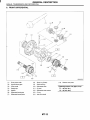
1. TRANSMISSION MOUNTING
P
Pitching stopper
Rear cushion rubber
(3) Crossmember
(4) Stopper
(1)
(2)
’1I
t
Tightening torque: N.m (kgf-m, ft-lb)
T1: 35 (3.6, 26)
T2: 39 (4.0,29)
T3: 50 (5.1, 37)
T4: 58 (5.9, 43)
T5: 70 (7.1, 51)
AT-4
I
GENERAL DESCRIPTION
AUTOMATIC TRANSMISSION
C: CAUTION
Wear working clothing, including a cap, protective goggles, and protective shoes during operation.
Remove contamination including dirt and corrosion before removal, installation, and disassembly.
Keep the disassembled parts in order and protect them from dust or dirt.
Until the oil pan is removed, do not place with the
oil pan side facing up to prevent foreign matter from
entering the valve body.
Before removal, installation or disassembly, be
sure to clarify the failure. Avoid unnecessary removal, installation, disassembly and replacement.
When disassembling the-case and other light alloy parts, use a plastic hammer to force it apart. Do
not pry it apart with a screwdriver or other tool.
Be careful not to burn your hands, because each
part on the vehicle is hot after running.
~ . ..
Use SUBARU genuine gear oil, grease etc. or
the equivalent. Do not mix gear oil, grease etc. with
that of another grade or from other manufacturers.
Be sure to tighten fasteners including bolts and
nuts to the specified torque.
Place shop jacks or safety stands at the specified
points.
Apply gear oil onto sliding or revolution surfaces
before installation.
Replace deformed or otherwise damaged snap
rings with new ones.
Before installing O-rings or oil seals, apply sufficient amount of ATF fluid to avoid damage and deformation.
Be careful not to incorrectly install or fail to install
O-rings, snap rings and other such parts.
Before securing a part on a vice, place cushioning material such as wood blocks, aluminum plate,
or shop cloth between the part and the vice.
Avoid damaging the mating surface of the case.
Before applying sealant, completely remove the
old seal.
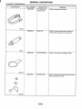
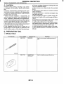
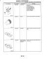
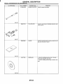
D: PREPARATION TOOL
1. SPECIAL TOOLS
~
ILLUSTRATION
TOOL NUMBER
398527700
DESCRIPTION
PULLER ASSY
REMARKS
Used for removing and installing extension case
roller bearing.
Used for installing extension oil seal.
AT-5
I
AUTOMATIC TRANSMISSION
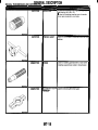
I--ILLUSTRATION
I
I
I
GENERAL DESCRIPTION
TOOL NUMBER
498575400
DESCRIPTION
OIL PRESSURE
GAUGE ASSY
REMARKS
Used for measuring oil pressure.
498897200
4DAPTER
Used for oil pump housing when measuring
reverse clutch pressure and line pressure.
498545400
-ILTER WRENCH
Jsed for removing and installing ATF filter.
498277200
;TOPPER SET
Jsed for removing and installing automatic trans.
nission assembly to engine.
B3M204C
B3M2041
B3M2043
AT-6
3
GENERAL DESCRIPTION
I
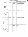
ILLUSTRATION
I
AUTOMATIC TRANSMISSION
REMARKS
Used for supporting engine.
TOOLNUMBER
41099AA020
DESCRIPTION
NGINE SUPPORT
41099AA010
INGINE SUPPORT
3RACKET
Jsed for supporting engine.
:RANK PULLEY
WRENCH
Used for removing and installing bolts which hold
torque converter clutch and drive plate.
CARTRIDGE
Troubleshooting for electrical systems.
B3M1976
~
I
B3M1975
Turbo model
499977300
Non-turbo model
499977100
B2M4157
I
24082AA150
(Newly adopted tool
B2M3876
AT-7
I
GENERAL DESCRIPTION
AUTOMATIC TRANSMISSION
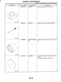
ILLUSTRATION
TOOL NUMBER
22771AA030
DESCRIPTION
SELECT MONITOR
KIT
REMARKS
Troubleshooting for electrical systems.
English:
22771AA030 (Without printer)
German:
22771AA070 (Without printer)
French:
22771AA080 (Without printer)
Spanish:
22771AA090 (Without printer)
STOPPER PIN
Used for installing and adjusting inhibitor switch.
B2M3877
499267300
B3M2008
2. GENERAL PURPOSE TOOLS
TOOL NAME
REMARKS
AT-8
AUTOMATIC TRANSMISSION FLUID
AUTOMATIC TRANSMISSION
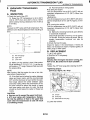
2. Automatic Transmission
Fluid
A: INSPECTION
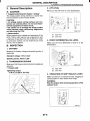
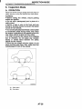
1) Check the level of the ATF.
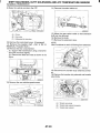
(1) Raise the ATF temperature to 60 to 80°C
(140 to 176°F) from 40 to 60°C (104 to 140°F)
(when cold) by driving a distance of 5 to 10 km (3
to 6 miles).
NOTE:
The level of ATF varies with fluid temperature. Pay
attention to the fluid temperature when checking oil
level.
(4) Fluid temperature rising speed:
By idling the engine
Time for temperature rise to 60°C (140°F) with atmospheric temperature of 0°C (32°F): More than
25 minutes
<Reference>
Time for temperature rise to 30°C (86°F) with atmospheric temperature of 0°C (32°F): Approx. 8 minutes
By running the vehicle
Time for temperature rise to 60°C (140°F) with atmospheric temperature of 0°C (32°F): More than
10 minutes
(5) Method for checking fluid level upon delivery
or at periodic inspection:
Check fluid level after a warm-up run of approx.
10 minutes. During the warm-up period, the automatic transmission functions can also be
checked.
2) Check the fluid for leaks.
Check for leaks in the transmission. If there are
leaks, it is necessary to repair or replace gasket, oil
seals, plugs or other parts.
B: REPLACEMENT
B3M1020B
1) Lift-up the vehicle.
2) Drain the ATF completely.
(A) ATF level gauge
(B) Upper level
(C) Lower level
(2) Make sure the vehicle is level. After selecting all positions (P, R, N, D, 3, 2, l ) , set the select leveler in “P” range. Measure fluid level with
the engine idling.
NOTE:
After running, idle the engine for one or two minutes before measurement.
(3) If the fluid level is below the center between
upper and lower marks, add the recommended
ATF until the fluid level is found within the specified range (above the center between upper
and lower marks). When the transmission is hot,
the level should be above the center of upper
and lower marks, and when it is cold, the level
should be found below the center of these two
marks.
CAUTION:
Use care not to exceed the upper limit level.
ATF level varies with temperature. Remember that the addition of fluid to the upper limit
mark when the transmission is cold will result
in overfilling of fluid.
CAUTION:
Directly after the engine has been running, the
ATF is hot. Be careful not to burn yourself.
NOTE:
Tighten the ATF drain plug after draining the ATF.
Tightening torque:
25 N-m (2.5 kgf-m, 18.1 ft-lb)
(A) Oil pan
(B) Drain plug
(C) Differential oil drain plug
3) Lower the vehicle.
AT-9
I
I
AUTOMATIC TRANSMISSION FLUID
AUTOMATIC TRANSMISSION
4) Pour ATF into the oil charge pipe.
Recommended fluid:
Dexron Ill type automatic transmission fluid
Capacity:
Fill the same amount of fluid drained from the
drain plug hole.
Capacity when transmission is overhauled:
9.3-9.6 8 (9.8- 10.1 USqt, 8.2-8.4Imp
qt)
5) Check the level and leaks of the ATF.
<Ref. to AT-9, INSPECTION, Automatic Transmission Fluid.>
AT-I 0
I
DIFFERENTIAL GEAR OIL
AUTOMATIC TRANSMISSION
B: REPLACEMENT
3. Differential Gear Oil
1) Lift-up the vehicle.
2) Drain the differential gear oil completely.
A: INSPECTION
1) Park the vehicle on a level surface.
2) Remove the oil level gauge and wipe it clean.
3) Reinsert the level gauge all the way. Be sure that
the level gauge is correctly inserted and in the
proper orientation.
4) Remove it again and note the reading. If the differential gear oil level is below the “L” line, add oil to
bring the level up to the “F’ line.
5) To prevent overfilling the differential gear oil, do
not add oil above the ‘IF line.
c
.
I
CAUTION:
Directly after the engine has been running, the
differential gear oil is hot. Be careful not to burn
yourself.
NOTE:
Tighten the differential gear oil drain plug after
draining the differential gear oil.
Tightening torque:
44 N.m (4.5 kgf-m, 32.5 ff-16)
.
I
s3M0478A
(A) Upper level
(B) Lower level
(A) Oil pan
(B) Drain plug
(C) Differential oil drain plug
3) Lower the vehicle.
4) Pour gear oil into the gauge hole.
Recommended fluid:
Use GL-5 or equivalent.
Gear oil capacity:
1.2 8 (1.3 US qt, 1.1 Imp qt)
5) Check the level of the differential gear oil.
<Ref. to AT-1 1, INSPECTION, Differential Gear
Oil.>
AT-I 1
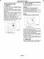
ROAD TEST
AUTOMATIC TRANSMISSION
4. RoadTest
A: INSPECTION
1. GENERAL PRECAUTION
Road tests should be conducted to properly diagnose the condition of the automatic transmission.
CAUTION:
When performing the test, do not exceed posted speed limit.
2. D RANGE SHIFT FUNCTION
Check shifting between 1st a 2nd w 3rd a 4th
while driving on normal city streets.
3. D RANGE SHIFT SHOCK
Check the shock level when shifting up during normal driving.
4. KICK-DOWN FUNCTION
Check kick-down for each gear. Also check the
krick-down shock level.
-
5. ENGINE BRAKE OPERATION
Check the 3rd gear engine brake when shifting
3rd range while driving in 4th gear of
between D
D range [50 to 60 km/h (31 to 37 MPH)].
Check the 2nd gear engine brake when shifting
between 3
2 range while driving in the 3 range
3rd gear [40 to 50 km/h (25 to 31 MPH)].
Check the 1st gear engine brake when shifting
between 2 -1 range while driving in the 2 range
2nd gear [20 to 30 km/h (12 to 19 MPH)].
6. LOCK-UP FUNCTION
Check that rpm does not change sharply when the
axle pedal is lightly depressed when driving on flat
roads at normal speed in the lock-up range.
7. P RANGE OPERATION
Stop the vehicle on an uphill grade of 5% or more
and shift to “P” range. Check that the vehicle does
not move when the parking brake is released.
8. UNUSUAL SOUNDS AND VIBRATION
Check for unusual sounds and vibration while driving and during shifting.
9. CLIMBING CONTROL FUNCTION
Check that the gear remains in 3rd when going
up a grade.
Check that the gear remains in 3rd when applying the brakes while going down a grade.
10.01L LEAKS
After the driving test, inspect for oil leaks.
AT-I 2
I
I
STALL TEST
AUTOMATIC TRANSMISSION
5. Stall Test
A: INSPECTION
1. GENERAL INFORMATION
The stall test is of extreme importance in diagnosing the condition of the automatic transmission and
the engine. It should be conducted to measure the
engine stall speeds in “R” and “2” ranges.
Purposes of the stall test:
1) To check the operation of the automatic transmission clutch.
2) To check the operation of the torque converter
clutch.
3) To check engine performance.
2. TEST METHODS
1) Preparations before test:
(1) Check that the throttle valve opens fully.
(2) Check that the engine oil level is correct.
c _ . (3) Check that the coolant level is correct.
(4) Check that the ATF level is correct.
(5) Check that the differential gear oil level is
correct.
(6) Increase ATF temperature to 50 to 80°C
(122 to 176°F) by idling the engine for approximately 30 minutes (with select lever set to “N” or
lip”).
2) Install an engine tachometer at a location visible
from the driver’s compartment and mark the stall
speed range on the tachometer scale.
3) Place the wheel chocks at the front and rear of all
wheels and engage the parking brake.
4) Move the manual linkage to ensure it operates
properly, and shift the select lever to the “2” range.
5) While forcibly depressing the foot brake pedal,
gradually depress the accelerator pedal until the
engine operates at full throttle.
7) Shift the select lever to Neutral, and cool down
the engine by idling it for more than one minute.
8) Record the stall speed.
9) If the stall speed in “2” range is higher than specifications, low clutch slipping and “2-4 brake slipping” may occur. To identify it, conduct the same
test as above in D range.
10) Perform the stall tests with the select lever in
the R range.
NOTE:
Do not continue the stall test for MORE THAN
FIVE SECONDS at a time (from closed throttle, fully open throttle to stall speed reading). Failure to
follow this instruction causes the engine oil and
ATF to deteriorate and the clutch and brake to be
adversely affected.
Be sure to cool down the engine for at least one
minute after each stall test with the select lever set
in the “P’ or ‘IN” range and with the idle speed lower
than 1,200 rpm.
If the stall speed is higher than the specified
range, attempt to finish the stall test in as short a
time as possible, in order to prevent the automatic
transmission from sustaining damage.
Stall speed (at sea level):
Non-turbo model: 2,100 -2,600 rpm
Turbo model: 2,600 - 3,300 rpm
03M1589E
(A) Brake pedal
(B) Accelerator pedal
6) When the engine speed is stabilized, read that
speed quickly and release the accelerator pedal.
AT-1 3
I
STALL TEST
AUTOMATIC TRANSMISSION
3. EVALUATION
Stall speed (at sea level)
Cause
Position
Less than specifications
~
Greater than specifications
R
2
I
Erroneous engine operation
Torque converter clutch's one-way clutch slipping
Line pressure too low
Low clutch slipping
One-wav clutch malfunctionim
Line pressure too low
Reverse clutch slipping
Low & reverse brake slipping
Line pressure too low
Low clutch slipping
2-4 brake slipping
AT-I 4
-
I
TIME LAG TEST
AUTOMATIC TRANSMISSION
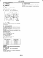
6. Time Lag Test
A: INSPECTION
1. GENERAL INFORMATION
If the select lever is shifted while the engine is
idling, there will be a certain time elapse or lag before the shock can be felt. This is used for checking
the condition of the low clutch, reverse clutch, low &
reverse brake and one-way clutch.
CAUTION:
Perform the test at normal operation fluid
temperature 60 to 80°C (140 to 176°F).
Be sure to allow a one minute interval between tests.
Make three measurements and take the average value.
2. TEST METHODS
1) Fully apply the parking brake.
-2.)Start the engine.
3) Check the idling speed (NC OFF).
4) Shift the select lever from “N” to “D” range.
Using a stop watch, measure the time it takes from
shifting the lever until the shock is felt.
Time lag: Less than 1.2 seconds
5 ) In the same manner, measure the time lag for
“N” + “R”.
Time lag: Less than 1.5 seconds
3. EVALUATION
1) If “N” + ‘ID time lag is longer than specified:
Line pressure too low
Low clutch worn
One-way clutch not operating properly
2) If “N” + “R” time lag is longer than specified:
Line pressure too low
Reverse clutch worn
Low & reverse brake worn
AT-I 5
I
LINE PRESSURE TEST
AUTOMATIC TRANSMISSION
7. Line Pressure Test
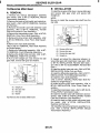
2. TEST METHODS
A: MEASUREMENT
1) Temporarily attach the ST to a suitable place in
the driver’s compartment, remove the blind plug located in front of the toe board and pass the hose of
the ST to the engine compartment.
ST 498575400
OIL PRESSURE GAUGE
ASSY
1. GENERAL INFORMATION
If the clutch or the brake shows a sign of slippage or
shifting sensation is not correct, the line pressure
should be checked.
Excessive shocks during upshifting or shifting
takes place at a higher point than under normal circumstances, may be due to the line pressure being
too high.
Slippage or inability to operate the vehicle may,
in most cases, be due to loss of oil pressure for the
operation of the clutch, brake or control valve.
1) Line pressure measurement (under no load):
CAUTION:
Before measuring line pressure, jack-up all
wheels.
Maintain temperature of ATF at approximately 50°C (122°F) during measurement.
(ATF will reach the above temperature after
idling the engine for approximately 30 minutes
with select lever in “N” or “P”.)
2) Line pressure measurement (under heavy load):
CAUTION:
Before measuring line pressure, apply both
foot and parking brakes with all wheels
chocked (Same as for “stall” test conditions).
Measure the line pressure when the select lever is in “R”, “2” with engine under stall conditions.
Measure the line pressure within 5 the seconds after shifting the select lever to each position. (If the line pressure needs to be measured
again, allow the engine to idle and then stop.
Wait for at least one minute before measurement.)
Maintain the temperature of ATF at approximately 50°C (122°F) during measurement. (ATF
will reach the above temperature after idling the
engine for approximately 30 minutes with the
select lever in “N” or “P”.)
(A) Pressure gauge hose
(B) Hole in toe board (blind plug hole)
(C) Brake pedal
2) Remove the test plug and install the ST instead.
ST 498897200
OIL PRESSURE GAUGE
ADAPTER
(A) Test plug
3) Connect ST1 with ST2.
ST1 498897200 OIL PRESSURE GAUGE
ADAPTER
ST2 498575400 OIL PRESSURE GAUGE
ASSY
AT-16
LINE PRESSURE TEST
4) Check for duty ratio changes by opening and
closing the throttle valve using the Subaru Select
Monitor.
(1) Insert the cartridge to the Subaru Select
Monitor. <Ref. to AT-5, PREPARATION TOOL,
General Description.>
(2) Connect the Subaru Select Monitor to data
link connector.
5 ) Check the line pressure in accordance with the
following chart.
3. EVALUATION
Standard line Dressure
Range
position
Line pressure duty
ratio (Yo)
Throttle
position
Full open
Full open
D
100
Full closed
1
Line pressure
kPa (kgkm’, psi)
1,128-1,304
(11.5 - 13.3,
164- 189)
1,520 - 1,716
(15.5 - 17.5,
220 - 249)
304 - 412
(3.1 - 4.2, 44 - 60)
AT-I 7
I
AUTOMATIC TRANSMISSION
I
TRANSFERCLUTCHPRESSURETEST
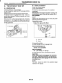
AUTOMATIC TRANSMISSION
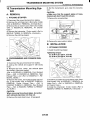
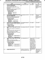
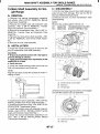
8. Transfer Clutch Pressure
Test
2. EVALUATION
MTP model
A: INSPECTION
NOTE:
If the oil pressure is not produced or if it does not
change in the AWD mode, the transfer duty solenoid or transfer valve assembly may be malfunctioning. If the oil pressure is produced in the FWD
mode, the problem is similar to that in the AWD
mode.
1. TEST METHODS
MPT model
Check the transfer clutch pressure in accordance
with the following chart in the same manner as with
line pressure. <Ref. to AT-16, Line Pressure Test.>
ST 498897700
OIL PRESSURE ADAPTER
SET
ST 498575400
OIL PRESSURE GAUGE
ASSY
AWD mode: “D” range
FWD mode: “P”range, engine speed 2,000 rpm
Standard transfer clutch Dressure kPa (ka/cm2. Dsi)
FWD
Duty ratio Throttle
AWD mode
position
mode
(%)
932 - 1,089
(9.5-11.1,
closed
CAUTION:
Before setting in FWD mode, install the spare
fuse on FWD mode switch.
c.
~
2/3 t hrottle
216 - 294
(2.2 - 3.0, 31 - 43)
Throttle
position
Full
closed
2/3 throttle
Standard transfer clutch pressure
kPa (kg/cm2,psi)
932 - 1,089
(9.5-11.1, 135-158)
216-294
(2.2 - 3.0, 31 - 43)
1
t
Duty ratio
(Yo)
5
60
(A) Test plug
VTD model
Check the transfer clutch pressure in accordance
with the following chart in the same manner as with
line pressure.
ST 498897700
OIL PRESSURE ADAPTER
SET
ST 498575400
OIL PRESSURE GAUGE
ASSY
7
H3M18408
(A) Test plug
AT-I 8
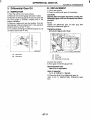
AUTOMATIC TRANSMISSION ASSEMBLY
AUTOMATIC TRANSMISSION
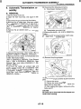
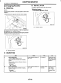
9. Automatic Transmission Assembly
10) Disconnect the following connectors:
(1) Transmission harness connector
A: REMOVAL
1) Set the vehicle on the lift.
2) Open the front hood fully, and support it with
stay.
3) Disconnect the ground terminal from battery.
4) Remove the air intake duct. (Non-turbo model)
<Ref. to IN(S0HC)-7, REMOVAL, Air Intake Duct.>
5 ) Remove the air cleaner case. (Non-turbo model)
<Ref. to IN(S0HC)-6, REMOVAL, Air Cleaner
Case.>
6) Remove the air cleaner case stay. (Non-turbo
model)
7) Remove the intercooler. (Turbo model) <Ref. to
IN(D0HC TURBO)-10, REMOVAL, Intercooler.>
8) Remove the front, center, rear exhaust pipe and
muffler. (Non-turbo model)
<Ref. to EX(S0HC)-5, REMOVAL, Front Exhaust
Pipe.>, <Ref. to EX(S0HC)-9, REMOVAL, Rear
Exhaust Pipe.> and <Ref. to EX(S0HC)-1 1, REMOVAL, Muffler.>
9) Remove the center, rear exhaust pipe and
muffer. (Turbo model) <Ref. to EX(D0HC TURBO)-8, REMOVAL, Center Exhaust Pipe.>, <Ref.
to EX(D0HC TURBO)-13, REMOVAL, Rear Exhaust Pipe.> and <Ref. to EX(D0HC TURBO)-14,
REMOVAL, Muffler.>
(2) Transmission ground terminal
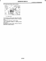
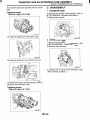
11) Remove the starter. <Ref. to SC-6, REMOVAL,
Starter.>
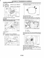
12) Install the ST to torque converter clutch case.
STOPPER SET
ST 498277200
13) Remove the pitching stopper.
14) Separate the torque converter clutch from drive
plate.
(1) Remove the service hole plug.
(2) Remove the bolts which hold torque converter clutch to drive plate.
(3) While rotating the engine, remove the other
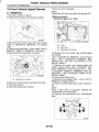
bolts using ST.
CAUTION:
Be careful not to drop bolts into the torque converter clutch housing.
AT-I 9
I
I
AUTOMATIC TRANSMISSION ASSEMBLY
AUTOMATIC TRANSMISSION
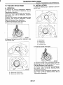
Turbo model
ST 499977300
Non-turbo model
ST 499977100
CRANK PULLEY WRENCH
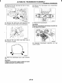
17) Remove the bolt which holds right upper side of
transmission to engine.
CRANK PULLEY WRENCH
B3M2044
15) Remove the ATF level gauge.
CAUTION:
Plug the opening to prevent entry of foreign
particles into transmission fluid.
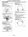
18) Lift-up the vehicle.
19) Remove the under cover.
20) Remove the heat shield cover. (If equipped)
21) Drain the ATF to remove the ATF drain plug.
(A) Oil pan
(6) Drain plug
16) Set the ST.
NOTE:
Also is available Part No. 41099AA010.
ST 41 099AA020 ENGINE SUPPORT ASSY
22) Disconnect the ATF cooler hoses from pipes of
transmission side, and remove the ATF level gauge
guide.
23) Remove the propeller shaft.
<Ref. to DS-14, REMOVAL, Propeller Shaft.>
24) Remove the shift select cable. <Ref. to CS-26,
REMOVAL, Select Cable.>
25) Disconnect the stabilizer link from transverse
link.
AT-20
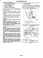
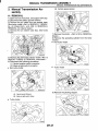
AUTOMATIC TRANSMISSION ASSEMBLY
AUTOMATIC TRANSMISSION
26) Remove the bolt securing ball joint of transverse link to housing.
30) Remove the transmission rear crossmember
from vehicle.
S4M0090
27) Remove the spring pins and separate front
drive shafts from each side of the transmission.
31) Remove the transmission.
CAUTION:
Move the transmission and torque converter as
a unit away from engine.
Remove the nuts which hold lower side of
transmission to engine.
32) Separate transmission assembly and rear
cushion rubber.
I
v
B3M2047
29) Place the transmission jack under transmission.
CAUTION:
Make sure that the support plates of transmission jack don't touch the oil pan.
AT-2 1
I
I
I
AUTOMATIC TRANSMISSION ASSEMBLY
AUTOMATIC TRANSMISSION
B: INSTALLATION
1) Install the rear cushion rubber to transmission
assembly.
Tightening torque:
39 N.m (4.0 kgf-m, 29 ft-lb)
2) Install the ST to torque converter clutch case.
ST 498277200
STOPPER SET
3) Install the transmission onto engine.
. (1) Gradually raise the transmission with transmission jack.
-_
6) Tighten the nuts and bolts which hold lower side
of transmission to engine.
Tightening torque:
50 N-m (5.1 kgf-m, 36.9 ft-lb)
7) Lower the vehicle.
8) Connect the engine and transmission.
(1) Remove the ST from torque converter clutch
case.
NOTE:
Be careful not to drop the ST into the torque converter clutch case when removing the ST.
ST 498277200
STOPPER SET
(2) Install the starter.
<Ref. to SC-7, INSTALLATION, Starter.>
(3) Tighten the bolt which holds right upper side
of transmission to engine.
Tightening torque:
50 N.m (5.1 kgf-m, 36.9 ft-lb)
(2) Engage them at splines.
4) Install the transmission rear crossmember.
Tightening torque:
T1: 35 N-m (3.6 kgf-m, 26 ft-lb)
T2: 70 Nom(7.1 kgf-m, 51.4 ft-lb)
03M2044
5) Take off the transmission jack.
AT-22
I
AUTOMATIC TRANSMISSION ASSEMBLY
AUTOMATIC TRANSMISSION
9) Install the torque converter clutch to drive plate.
(1) Tighten the bolts which hold torque converter clutch to drive plate.
(2) Tighten the other bolts while rotating the engine by using ST.
CAUTION:
Be careful not to drop bolts into the torque converter clutch housing.
Turbo model
ST 499977300
CRANK PULLEY WRENCH
Non-turbo model
ST 499977100
CRANK PULLEY WRENCH
12) Lift-up the vehicle.
Install the front drive shafts into transmission.
(1) Lift-up the vehicle.
(2) Install the front drive shaft into transmission.
(3) Drive the spring pin into chamfered hole of
drive shaft.
CAUTION:
Always use a new spring pin.
Tightening torque:
25 N.m (2.5 kgf-m, 18.1 ft-lb)
13) Install the ball joint into housing.
14) Connect the stabilizer link to transverse link,
and temporarily tighten the bolts.
CAUTION:
Discard the loosened self-locking nut and replace with a new one.
(3) Clog the service hole with a plug.
10) Remove the ST.
Tightening torque:
T1: 30 N.m (3.1 kgf-m, 22.4 ft-lb)
T2: 50 N-m (5.1 kgf-m, 37 ft-lb)
11) Install the pitching stopper.
Tightening torque:
T1: 50 N.m (5.1 kgf-m, 37 ft-lb)
T2: 58 N.m (5.9 kgf-m, 43 ft-lb)
15) Install the shift select cable onto select lever.
<Ref. to CS-27, INSTALLATION, Select Cable.>
16) Install the ATF level gauge guide, and connect
the ATF cooler hoses to pipe.
AT-23
1
I
AUTOMATIC TRANSMISSION ASSEMBLY
AUTOMATIC TRANSMISSION
17) Install the propeller shaft.
<Ref. to DS-15, INSTALLATION, Propeller Shaft.>
18) Install the heat shield cover. (If equipped)
19) Install the front, center, rear exhaust pipes and
muffler. (Non-turbo model)
<Ref. to EX(S0HC)-6, INSTALLATION, Front Exhaust Pipe.>, <Ref. to EX(S0HC)-9, INSTALLATION, Rear Exhaust Pipe.> and <Ref. to
EX(S0HC)-11, INSTALLATION, Muffler.>
20) Install the center, rear exhaust pipes and muffler. (Turbo model) <Ref. to EX(D0HC TURBO)-9,
INSTALLATION, Center Exhaust Pipe.>, <Ref. to
EX(D0HC TURBO)-13, INSTALLATION, Rear Exhaust Pipe.>, <Ref. to EX(D0HC TURBO)-14, INSTALLATION, Muff ler.>
21) Install the under cover.
22) Lower the vehicle.
23) Install the ATF level gauge.
c.
32) Check the select lever operation.
<Ref. to AT-28, INSPECTION, Inhibitor Switch.>
33) Check the ATF level. <Ref. to AT-9, Automatic
Transmission Fluid.>
34) Check the vehicle on the road tester.
<Ref. to AT-12, Road Test.>
.
24) Connect the following connectors:
(1) Transmission harness connectors
(2) Transmission ground terminal
25) Install the air cleaner case stay. (Non-turbo
model)
Tightening torque:
16 N.m (1.6 kgf-m, 11.6 ft-16)
26) Install the air cleaner case. (Non-turbo model)
<Ref. to IN(S0HC)-6, INSTALLATION, Air Cleaner
Case.>
27) Install the air intake duct. (Non-turbo model)
<Ref. to IN(S0HC)-7, INSTALLATION, Air Intake
Duct.>
28) Install the intercooler. (Turbo model) <Ref. to
IN(D0HC TURBO)-1 1, INSTALLATION, Intercooler.>
29) Connect the battery ground terminal.
30) Fill ATF up to the middle of the “COLD” side on
level gauge by using the gauge hole.
Recommended fluid:
Dexron Ill type automatic transmission fluid
Fluid capacity:
9.3-9.6 0 (9.8-10.1 USqt, 7.4-7.7lmp
qt)
31) Take off the vehicle from lift arms.
AT-24
1
TRANSMISSION MOUNTING SYSTEM
AUTOMATIC TRANSMISSION
1O.Transmission Mounting System
A: REMOVAL
1. PITCHING STOPPER
6) Set the transmission jack under the transmission.
CAUTION:
Make sure that the support plates of transmission jack don't touch the oil pan.
7) Remove the crossmember.
1) Disconnect the ground terminal from battery.
2) Remove the air intake duct. (Non-turbo model)
<Ref. to IN(S0HC)-7, REMOVAL, Air Intake Duct.>
3) Remove the air cleaner case. (Non-turbo model)
<Ref. to IN(S0HC)-6, REMOVAL, Air Cleaner
Case.>
4) Remove the intercooler. (Turbo model) <Ref. to
IN(D0HC TURBO)-10, REMOVAL, Intercooler.>
5) Remove the pitching stopper.
8) Remove the rear cushion rubber.
B: INSTALLATION
1. PITCHING STOPPER
1) Install the pitching stopper.
Tightening torque:
T I : 50 N.m (5.1 kgf-m, 37 ff-lb)
T2: 58 N.m (5.9 kgf-m, 43 ft-lb)
2. CROSSMEMBER AND CUSHION RUBBER
1) Disconnect the ground terminal from battery.
2) Jack-up the vehicle and support it with sturdy
racks.
3) Remove the front, center, rear exhaust pipes
and muffler. (Non-turbo model)
<Ref. to EX(S0HC)-5, REMOVAL, Front Exhaust
Pipe.>, <Ref. to EX(S0HC)-9, REMOVAL, Rear
Exhaust Pipe.> and <Ref. to EX(S0HC)-11, REMOVAL, Muffler.>
4) Remove the center, rear exhaust pipes and muffler. (Turbo model) <Ref. to EX(D0HC TURBO)-8,
REMOVAL, Center Exhaust Pipe.>, <Ref. to
EX(D0HC TURBO)-13, REMOVAL, Rear Exhaust
Pipe.>, <Ref. to EX(D0HC TURBO)-14, REMOVAL, Muffler.>
CAUTION:
When removing the exhaust pipes, be careful
each exhaust pipe does not drop out.
5) Remove the heat shield cover. (If equipped)
2) Install the air intake duct and cleaner case. (Nonturbo model) <Ref. to IN(S0HC)-7, REMOVAL, Air
Intake Duct.>, <Ref. to IN(S0HC)-6, REMOVAL,
Air Cleaner Case.>
3) Install the intercooler. (Turbo model) <Ref. to
IN(D0HC TURBO)-10, REMOVAL, Intercooler.>
AT-25
I
I
TRANSMISSION MOUNTING SYSTEM
AUTOMATIC TRANSMISSION
C: INSPECTION
2. CROSSMEMBER AND CUSHION RUBBER
Repair or replace parts if the results of the inspection below are not satisfactory.
1) Install the rear cushion rubber.
1. PITCHING STOPPER
Tightening torque:
39 N.m (4.0 kgf-m, 29 ff-lb)
2 ) Install the crossmember.
Make sure that the pitching stopper is not bent or
damaged. Make sure that the rubber is not stiff,
cracked, or otherwise damaged.
Tightening torque:
T I : 35 N-m (3.6 kgf-m, 26 ft-lb)
T2: 70 N.m (7.1 kgf-m, 51.4 ff-lb)
2. CROSSMEMBER AND CUSHION RUBBER
Make sure that the crossmember is not bent or
damaged. Make sure that the cushion rubber is not
stiff, cracked, or otherwise damaged.
c.
3) Remove the transmission jack.
4) Install the heat shield cover. (If equipped)
5 ) Install the front, center, rear exhaust pipes and
the muffler. (Non-turbo model)
<Ref. to EX(S0HC)-6, INSTALLATION, Front Exhaust Pipe.>, <Ref. to EX(S0HC)-9, INSTALLATION, Rear Exhaust Pipe.> and <Ref. to
EX(S0HC)-11, INSTALLATION, Muffler.>
6) Install the center, rear exhaust pipes and muffler.
(Turbo model) <Ref. to EX(D0HC TURBO)-14, INSTALLATION, Muffler.>, <Ref. to EX(D0HC TURBO)-13, INSTALLATION, Rear Exhaust Pipe.>,
<Ref. to EX(D0HC TURBO)-9, INSTALLATION,
Center Exhaust Pipe.>
AT-26
EXTENSION CASE OIL SEAL
AUTOMATIC TRANSMISSION
11.Extension Case Oil Seal
A: INSPECTION
Make sure that the ATF does not leak from the joint
of the transmission and propeller shaft. If so, replace the oil seal. <Ref. to AT-27, REPLACEMENT, Extension Case Oil Seal.>
B: REPLACEMENT
1) Set the vehicle on the lift.
2) Disconnect the ground terminal from battery.
3) Lift up the vehicle.
4) Clean the transmission exterior.
5 ) Drain the ATF completely.
13) Install the rear exhaust pipe and muffler.
Non-turbo model
<Ref. to EX(S0HC)-9, INSTALLATION, Rear Exhaust Pipe.> and <Ref. to EX(S0HC)-11, INSTALLATION, Muffler.>
Turbo model
<Ref. to EX(D0HC TURBO)-14, INSTALLATION,
Muffler.>, <Ref. to EX(D0HC TURBO)-13, INSTALLATION, Rear Exhaust Pipe.>
14) Pour ATF and check the ATF level. <Ref. to AT9, Automatic Transmission Fluid.>
NOTE:
Tighten the ATF drain plug after draining the ATF.
Tightening torque:
25 N-m (2.5 kgf-m, 18.1 ft-lb)
(A) Oil pan
(B) Drain plug
(C) Differentialoil drain plug
6) Remove the rear exhaust pipe and muffler.
Non-turbo model
<Ref. to EX(S0HC)-9, REMOVAL, Rear Exhaust
Pipe.> and <Ref. to EX(S0HC)-11, REMOVAL,
Muffler.>
Turbo model
<Ref. to EX(D0HC TURBO)-13, REMOVAL, Rear
Exhaust Pipe.>, <Ref. to EX(D0HC TURBO)-14,
REMOVAL, Muffler.>
7) Remove the heat shield cover. (If equipped)
8) Remove the propeller shaft. <Ref. to DS-14, REMOVAL, Propeller Shaft.>
9) Using the ST, remove the oil seal.
ST 398527700
PULLER ASSY
10) Using the ST, install the oil seal.
ST 498057300
INSTALLER
11) Install the propeller shaft. <Ref. to DS-15, INSTALLATION, Prope1ler Shaft.>
12) Install the heat shield cover. (If equipped)
AT-27
I
INHIBITOR SWITCH
AUTOMATIC TRANSMISSION
3) Check if there is continuity at equal points when
the select lever is turned 1.5" in both directions
from the N range.
If there is continuity in one direction and the continuity in the other or if there is continuity at unequal
points, adjust the inhibitor switch.<Ref. to AT-28,
ADJUSTMENT, Inhibitor Switch.>
I
Position
P
R
N
D
3
2
-.
Signal sent to TCM
I
Starter circuit
Back-up light circuit
1
PIN
R
Pin No.
4-3
4-2
4-1
4-8
4-7
4-6
I
4-5
12-11
10-9
Inhibitor switch side connector
f-----3
(A) Continuity does not exist.
(B) Continuity exists.
(C) 1.5"
I
4) Repeat the above checks. If there are abnormalities, adjust the select cable. <Ref. to CS-27, ADJUSTMENT, Select Cable.>
I
B: ADJUSTMENT
1) Shift the select lever to the N range.
2) Loosen the three inhibitor switch securing bolts.
3) Insert the ST as vertical as possible into the
holes in the inhibitor switch lever and switch body.
ST 499267300
STOPPER PIN
B3H0016e
4) Tighten the three inhibitor switch bolts.
Tightening torque:
3.4 N.m (0.35 kgf-m, 2.5 ft-lb)
5 ) Repeat the above checks. If the inhibitor switch
is determined to be "faulty", replace it.
AT-28
I
INHI BI T 0R SWITCH
AUTOMATIC TRANSMISSION
C: REMOVAL
1) Set up the vehicle on the lift.
2) Move the select lever to neutral position.
3) Remove the air cleaner case. (Non-turbo model)
<Ref. to IN(S0HC)-6, REMOVAL, Air Cleaner
Case.>
4) Remove the intercooler. (Turbo model) <Ref. to
IN(D0HC TURBO)-10, REMOVAL, Intercooler.>
5) Disconnect the inhibitor switch connector.
11) Remove the plate assembly from transmission
case.
(A) Select cable
(B) Plate ASSY
12) Remove the bolts.
c-
(A) Inhibitor switch
6) Remove the inhibitor switch connector from stay.
7) Lift-up the vehicle.
8) Remove the front exhaust pipe with center exhaust pipe. (Non-turbo model)
<Ref. to EX(S0HC)-5, REMOVAL, Front Exhaust
Pipe.>
9) Remove the center exhaust pipe. (Turbo model)
<Ref. to EX(D0HC TURBO)-8, REMOVAL, Center
Exhaust Pipe.>
10) Remove the snap pin from range select lever.
(A) Inhibitor switch
13) Move the range select lever to parking position
(left side).
(A) Snap pin
(B) Select cable
(C) Range select lever
(A) Range select lever
AT-29
I
INHIBITOR SWITCH
AUTOMATIC TRANSMISSION
14) Remove the inhibitor switch from transmission.
6) Install the plate assembly to transmission.
Tightening torque:
T: 24.5 N.m (2.50 kgf-m, 18.1 ff-16)
(A) Inhibitor switch
15) Disconnect the inhibitor switch harness from inhibitor switch.
(A) Select cable
(B) Plate ASSY
D: INSTALLATION
1) Connect the inhibitor switch harness to inhibitor
switch.
2) Install the inhibitor switch to transmission case.
7 ) Install the snap pin to range select lever
c.
(A) Snap ring
(B) Select cable
(C) Range select lever
(A) Inhibitor switch
3) Move the range select lever to neutral position.
4) Using the ST, tighten bolts of inhibitor switch.
ST 499267300
STOPPER PIN
Tightening torque:
3.4 N-m (0.35 kgf-m, 2.5 ff-16)
8) Install the front exhaust pipe with center exhaust
pipe. (Non-turbo model)
<Ref. to EX(S0HC)-6, INSTALLATION, Front Exhaust Pipe.>
9) Install the center exhaust pipe. (Turbo model)
<Ref. to EX(D0HC TURBO)-9, INSTALLATION,
Center Exhaust Pipe.>
10) Lower the vehicle.
11) Install the inhibitor switch connector from stay.
(A) Inhibitor switch
(B) Range select lever
5) Install the select cable to range select lever.
AT-30
INHIBITOR SWITCH
12) Connect the inhibitor switch connector.
(A) Inhibitor switch
13) Install the air cleaner case. (Non-turbo model)
<Ref. to IN(S0HC)-6, INSTALLATION,Air Cleaner
Case.>
14) Install the intercooler. (Turbo model)
<Ref. to IN(D0HC TURBO)-11, INSTALLATION,
Intercooler.>
1 5 ) Inspect the inhibitor switch. <Ref. to AT-28, INSPECTION, Inhibitor Switch.>
AT-31
1
AUTOMATIC TRANSMISSION
I
FRONT VEHICLE SPEED SENSOR
AUTOMATIC TRANSM ISSlON
13.Front Vehicle Speed Sensor
9) Drain the ATF completely.
NOTE:
Tighten the ATF drain plug after draining the ATF.
A: REMOVAL
1) Set up the vehicle on the lift.
2) Disconnect the ground terminal from battery.
Tightening torque:
25 N-m (2.5 kgf-m, 18.1 ft-lb)
3) Remove the air cleaner case. (Non-turbo model)
<Ref. to IN(SOHC)-6, REMOVAL, Air Cleaner
Case.>
4) Remove the intercooler. (Turbo model) <Ref. to
W(DOHC TURBO)-10, REMOVAL, Intercooler.>
5) Disconnect the transmission connector.
(A) Transmission connector
6) Remove the transmission connector from stay.
7) Lift-up the vehicle.
8) Clean the transmission exterior.
(A) Oil pan
(B) Drain plug
(C) Differential oil drain plug
IO) Remove the front, center, rear, exhaust pipes
and muffler.
<Ref. to EX(S0HC)-5, REMOVAL, Front Exhaust
Pipe.>, <Ref. to EX(S0HC)-9, REMOVAL, Rear
Exhaust Pipe.> and <Ref. to EX(S0HC)-11, REMOVAL, Muffler.>
11) Remove the center, rear exhaust pipes and
muffler. (Turbo model) <Ref. to EX(D0HC TURBO)-8, REMOVAL, Center Exhaust Pipe.>, <Ref.
to EX(D0HC TURBO)-13, REMOVAL, Rear Exhaust Pipe.>, <Ref. to EX(D0HC TURBO)-14, REMOVAL, Muffler.>
12) Remove the shield cover.
13) Remove the propeller shaft. <Ref. to DS-14,
REMOVAL, Propeller Shaft.>
14) Place the transmission jack under crossmember.
NOTE:
Place a shop cloth or equivalent between the
crossmember and transmission.
15) Remove the transmission rear crossmember
bolts.
\
AT-32
FRONT VEHICLE SPEED SENSOR
16) Lower the AT jack.
NOTE:
Do not separate the AT jack and transmission.
17) Remove the oil cooler outlet pipe.
CAUTION:
When removing the outlet pipe, be careful not
to lose the balls and springs used with retaining screws.
18) Remove the front and rear vehicle speed sensor and torque converter turbine speed sensor.
Front vehicle speed sensor and torque
converter turbine speed sensor
I
AUTOMATIC TRANSMISSION
20) Disconnect the duty solenoids and ATF temperature sensor connectors. Remove the connectors from clip and disconnect the connectors.
(A) Lock-up duty solenoid (Blue)
(A) Front vehicle speed sensor
(B) Torque converter turbine speed sensor
Rear vehicle speed sensor
(B)
(C)
(D)
(E)
Low clutch timing solenoid (Gray)
Line pressure duty solenoid (Red)
Shift solenoid 2 (Yellow)
Shift solenoid 1 (Green)
(F)
(G)
(H)
(I)
(J)
2-4 brake timing solenoid (Black)
2-4 brake duty solenoid (Red)
ATF temperature sensor
Transfer duty solenoid (Brown)
Transmission ground
21) Remove the harness assembly.
B: INSTALLATION
1) Pass the harness assembly through the hole in
the transmission case.
(A) Rear vehicle speed sensor
(B) Front vehicle speed sensor
19) Remove the oil pan.
AT-33
I
FRONT VEHICLE SPEED SENSOR
AUTOMATIC TRANSMISSION
2) Connect the harness connectors.
Connect the connectors of same color, and secure
the connectors to valve body sing clips.
6) Install the oil cooler outlet pipe.
Tightening torque (Transmission ground terminal):
8 N-m (0.8 kgf-m, 5.8 ft-lb)
Tightening torque:
25 N-m (2.5 kgf-m, 18.1 ft-lb)
7) Install the transmission rear crossmember bolts.
B2M22631
(A) Lock-up duty solenoid (Blue)
(B) Low clutch timing solenoid (Gray)
Line pressure duty solenoid (Red)
Shift solenoid 2 (Yellow)
Shift solenoid 1 (Green)
2-4 brake timing solenoid (Black)
2-4 brake duty solenoid (Red)
ATF temperature sensor
Transfer duty solenoid (Brown)
Transmission ground
3) Apply proper amount of liquid gasket to the entire oil pan mating surface.
Fluid packing:
Three Bond 12176
I
CAUTION:
Be sure to use a new aluminum washer.
Tightening torque:
75 Nom(7.6 kgf-m, 55 ft-lb)
8 ) Install the propeller shaft. <Ref. to DS-15, INSTALLATION, PropeIler Shaft.>
9) Install the shield cover. (If equipped)
10) Install the front, center, rear exhaust pipes and
muffler. (Non-turbo model)
<Ref. to EX(S0HC)-6, INSTALLATION, Front Exhaust Pipe.> and <Ref. to EX(S0HC)-9, INSTALLATION, Rear Exhaust Pipe.> and <Ref. to
EX(S0HC)-11, INSTALLATION, Muffler.>
11) Install the center, rear exhaust pipes and muffler. (Turbo model) <Ref. to EX(D0HC TURBO)14, INSTALLATION, Muffler.>, <Ref. to EX(D0HC
TURBO)-13, INSTALLATION, Rear Exhaust
Pipe.>, <Ref. to EX(D0HC TURBO)-9, INSTALLATION, Center Exhaust Pipe.>
12) Lower the vehicle.
13) Install the transmission connector to the stay.
14) Install the air cleaner case. (Non-turbo model)
<Ref. to IN(S0HC)-6, INSTALLATION, Air Cleaner
Case.>
15) Install the intercooler. (Turbo model). <Ref. to
IN(D0HC TURBO)-11, INSTALLATION, Intercooler.>
B3M1040
4) Install the oil pan.
Tightening torque:
25 N-m (2.5 kgf-m, 18.1 ff-lb)
5) Install the front and rear vehicle speed sensor,
and also the torque converter turbine speed sensor, and then fasten the harness.
Tightening torque:
7 N-m (0.7 kgf-m, 5. 1 ft-lb)
AT-34
REAR VEHICLE SPEED SENSOR
AUTOMATIC TRANSMISSION
14.Rear Vehicle Speed Sensor
A: REMOVAL
When removing the rear vehicle speed sensor, refer to “Front Vehicle Speed Sensor.” <Ref. to AT32, REMOVAL, Front Vehicle Speed Sensor.>
B: INSTALLATION
When installing the rear vehicle speed sensor, refer
to “Front Vehicle Speed Sensor.” <Ref. to AT-33,
INSTALLATION, Front Vehicle Speed Sensor.>
AT-35
I
TORQUE CONVERTER TURBINE SPEED SENSOR
AUTOMATIC TRANSMISSION
15.Torque Converter Turbine
Speed Sensor
A: REMOVAL
When removing the torque converter turbine speed
sensor, refer to “Front Vehicle Speed Sensor.’’
<Ref. to AT-32, REMOVAL, Front Vehicle Speed
Sensor.>
B: INSTALLATION
When installing the torque converter turbine speed
sensor, refer to “Front Vehicle Speed Sensor.”
<Ref. to AT-33, INSTALLATION, Front Vehicle
Speed Sensor.>
AT-36
I
CONTROL VALVE BODY
I
AUTOMATIC TRANSMISSION
5) Disconnect the duty solenoids and ATF temperature sensor connectors. Remove the connectors
from clip and disconnect the connectors.
16.Control Valve Body
A: REMOVAL
1) Lift-up the vehicle.
2) Clean the transmission exterior.
3) Drain the ATF completely.
NOTE:
Tighten the ATF drain plug after draining the ATF.
Tightening torque:
25 N.m (2.5 kgf-m, 18.7 ff-16)
B2M2269
(A) Oil pan
(B) Drain plug
(C) Differential oil drain plug
(A)
(B)
(C)
(D)
(E)
Lock-up duty solenoid (Blue)
Low clutch timing solenoid (Gray)
Line pressure duty solenoid (Red)
Shift solenoid 2 (Yellow)
Shift solenoid 1 (Green)
(F)
(G)
(H)
(I)
2-4 brake timing solenoid (Black)
2-4 brake duty solenoid (Red)
ATF temperature sensor
Transfer duty solenoid (Brown)
6) Remove the control valve. When removing the
control valve body, be careful not to interfere with
transfer duty solenoid wiring.
4) Remove the oil pan.
NOTE:
Remove and clean the magnet.
Remove the old gasket on the oil pan and transmission case completely.
I103;
AT-37
I
I
CONTROL VALVE BODY
AUTOMATIC TRANSMISSION
B: INSTALLATION
1) Set the range select lever in ‘IN” position.
2) Install the control valve and ground earth connectors.
5) Apply proper amount of liquid gasket to the entire oil pan mating surface.
Fluid packing:
Tree Bond 12178
Tightening torque:
8 N.m (0.8 kgf-m, 5.8 ft-lb)
B3M1040
6) Install the oil pan.
(A) Short bolts
(B) Long bolts
ij Connect all connector.
Tightening torque:
4.9 N-m (0.5 kgf-m, 3.6 ft-16)
7 ) Pour ATF into the oil charge pipe. <Ref. to AT-9,
Automatic Transmission Fluid.>
8) Check the level of the ATF.
<Ref. to AT-9, Automatic Transmission Fluid.>
C: DISASSEMBLY
Refer to “AUTOMATIC TRANSMISSION” <Pub.
No. G0853ZE> a separate publication.
D: ASSEMBLY
Refer to “AUTOMATIC TRANSMISSION” <Pub.
No. G0853ZE> a separate publication.
E: INSPECTION
Refer to “AUTOMATIC TRANSMISSION” <Pub.
No. G0853ZE> a separate publication.
Lock-up duty solenoid (Blue)
Low clutch timing solenoid (Gray)
Line pressure duty solenoid (Red)
Shift solenoid 2 (Yellow)
Shift solenoid 1 (Green)
2-4 brake timing solenoid (Black)
2-4 brake duty solenoid (Red)
ATF temperature sensor
Transfer duty solenoid (Brown)
4) Attach the magnet at the specified position.
AT-38
SHIFT SOLENOIDS, DUTY SOLENOIDS AND ATF TEMPERATURE SENSOR
AUTOMATIC TRANSMISSION
17.Shift Solenoids, Duty Solenoids and ATF Temperature
Sensor
8) Remove the solenoids, duty solenoids and ATF
temperature sensor.
A: REMOVAL
1) Set the vehicle on the lift.
2) Disconnect the ground terminal from battery.
3) Lift-up the vehicle.
4) Clean the transmission exterior.
5) Drain the ATF completely.
NOTE:
Tighten the ATF drain plug after draining the ATF.
Tightening torque:
25 Nom(2.5 kgf-m, 18.1 ff-lb)
c-
(A) Lock-up duty solenoid (Blue)
(B) Low clutch timing solenoid (Gray)
(C) Line pressure duty solenoid (Red)
(D) Shift solenoid 2 (Yellow)
(E) Shift solenoid 1 (Green)
(F) 2-4 brake timing solenoid (Black)
(G) 2-4 brake duty solenoid (Red)
(H) ATF temperature sensor
.
1. TRANSFER DUTY SOLENOID AND
TRANSFER VALVE BODY
(A) Oil pan
(B) Drain plug
6) Remove the oil pan.
7) Disconnect the solenoid and sensor connectors.
Remove the connectors from clip and disconnect
the connectors.
1) Set up the vehicle on the lift.
2) Disconnect the ground terminal from battery.
3) Remove the air intake duct. <Ref. to IN(S0HC)7, REMOVAL, Air Intake Duct.>
4) Remove the air cleaner case. <Ref. to IN(S0HC)-6, REMOVAL, Air Cleaner Case.>
5 ) Remove the intercooler. (Turbo model) <Ref. to
IN(D0HC TURBO)-10, REMOVAL, Intercooler.>
6) Remove the pitching stopper.
I
(G)
(F)
B2M2263J
Lock-up duty solenoid (Blue)
Low clutch timing solenoid (Gray)
Line pressure duty solenoid (Red)
Shift solenoid 2 (Yellow)
Shift solenoid 1 (Green)
2-4 brake timing solenoid (Black)
2-4 brake duty solenoid (Red)
ATF temperature sensor
Transfer duty solenoid (Brown)
7) Remove the front exhaust pipe with center exhaust pipe. (Non-turbo model)
With OBD
<Ref. to EX(S0HC)-5, REMOVAL, Front Exhaust
Pipe.>
8) Remove the center exhaust pipe. (Turbo model)
<Ref. to EX(D0HC TURBO)-8, REMOVAL, Center
Exhaust Pipe.>
AT-39
I
I
SHIFT SOLENOIDS, DUTY SOLENOIDS AND ATF TEMPERATURE SENSOR
AUTOMATIC TRANSMISSION
9) Raise the vehicle and drain the ATF
14) Remove the select cable nut.
G3M0308
15) Move the gear select cable so that extension
bolts can be removed.
16) Remove the bolts.
17) Remove the extension case.
(A) Oil pan
(B) Drain plug
(C) Defferential oil drain plug
10) Remove the heat shield cover. (If equipped)
11) Remove the propeller shaft. <Ref. to DS-14,
REMOVAL, Propeller Shaft.>
12) Remove the rear crossmember.
.(1) Support the transmission using a transmission jack and raise slightly.
(2) Remove the bolts and nuts as shown in the
figure.
NOTE:
Use a container to catch oil flowing from extension.
-_
18) Disconnect the transfer duty solenoid connector.
19) Remove the transfer duty solenoid and transfer
valve body.
13) Remove the rear vehicle speed sensor
B3M1045F
(A) Transfer valve body
(B) Transfer duty solenoid connector
(C) Transfer duty solenoid
AT-40
I
SHIFT SOLENOIDS, DUTY SOLENOIDS AND ATF TEMPERATURE SENSOR
AUTOMATIC TRANSMISSION
B: INSTALLATION
1) Install the solenoids and ATF temperature sensor.
Tightening torque:
T: 8 N-m (0.8 kgf-m, 5.8 ft-lb)
3) Apply proper amount of liquid gasket to the entire oil pan mating surface.
Fluid packing:
Tree Bond 12178
I
B3M 1040
4) Install the oil pan.
Tightening torque:
4.9 N.m (0.50 kgf-m, 3.6 ft-lb)
(A) Lock-up duty solenoid (Blue)
c-
-
(B)
(C)
(D)
(E)
(F)
(G)
(H)
Low clutch timing solenoid (Gray)
Line pressure duty solenoid (Red)
Shift solenoid 2 (Yellow)
Shift solenoid 1 (Green)
2-4 brake timing solenoid (Black)
2-4 brake duty solenoid (Red)
ATF temperature sensor
2) Connect the harness connectors.
Connect the connectors of same color, and secure
the connectors to valve body using clips.
(A) Oil pan
(B) Drain plug
5 ) Fill ATF up to the middle of the “COLD” side on
level gauge by using the gauge hole. <Ref. to AT-9,
Automatic Transmission Fluid.>
6) Check the ATF level. <Ref. to AT-9, Automatic
Transmission Fluid.>
(G,
CF,
B2M2263J
Lock-up duty solenoid (Blue)
Low clutch timing solenoid (Gray)
Line pressure duty solenoid (Red)
Shift solenoid 2 (Yellow)
Shift solenoid 1 (Green)
2-4 brake timing solenoid (Black)
2-4 brake duty solenoid (Red)
ATF temperature sensor
Transfer duty solenoid (Brown)
AT-4 1
I
SHIFT SOLENOIDS, DUTY SOLENOIDS AND ATF TEMPERATURE SENSOR
AUTOMATIC TRANSMISSION
1. TRANSFER DUTY SOLENOID AND
TRANSFER VALVE BODY
4) Install the rear crossmember.
(1) Tighten the bolts.
1) Install the transfer duty solenoid and transfer
valve body.
(1) Install the transfer duty solenoid and transfer valve body.
Tightening torque:
T I : 35 N-m (3.6 kgf-m, 26 ft-lb)
T2: 70 N.m (7.1 kgf-m, 51.4 ft-lb)
Tightening torque:
T: 8 N-m (0.8 kgf-m, 5.8 ft-lb)
(2) Connect the transfer duty solenoid connector.
(2) Lower and remove the transmission jack.
5) Install the propeller shaft. <Ref. to DS-15, INSTALLATION, Propeller Shaft.>
6) Install the front exhaust pipe and center exhaust
pipe.
7) Lower and remove the jack.
8) Connect the transmission harness connector.
c.
(A) Transfer valve body
(B) Transfer duty solenoid connector
(C) Transfer duty solenoid
2) Install the extension case to transmission case.
(1) Tighten eleven bolts.
Tightening torque:
25 N-m (2.5 kgf-m, 18.1 ft-lb)
(2) Adjust the select cable. <Ref. to CS-27, ADJUSTMENT, Select Cable.>
3) Install the rear vehicle speed sensor.
Tightening torque:
T: 7 N.m (0.7 kgf-m, 5. t ft-lb)
9) Install the pitching stopper.
Tightening torque:
T1: 50 N.m (5.1 kgf-m, 37 ft-lb)
T2: 58 N.m (5.9 kgf-m, 43 ft-lb)
IO) Install the air cleaner case and duct.
AT-42
e
I
SHIFT SOLENOIDS, DUTY SOLENOIDS AND ATF TEMPERATURE SENSOR
AUTOMATIC TRANSMISSION
11) Fill ATF up to the middle of the "COLD" side on
level gauge by using the gauge hole. <Ref. to AT-9,
Automatic Transmission Fluid.>
12) Check the ATF level. <Ref. to AT-9, Automatic
Transmission Fluid.>
AT-43
I
ATF FILTER
AUTOMATIC TRANSMISSION
18.ATF Filter
C: INSPECTION
A: REMOVAL
Replace the part if any defect is found from the inspection.
Check for rust, hole, ATF leaks, and other damage.
NOTE:
The ATF filter is maintenance free.
1) Lift-up the vehicle.
2) Using the ST, remove the ATF filter.
ST 498545400
OIL FILTER WRENCH
Torque wrench length
mm (in)
100 (3.94)
150 (5.91)
200 (7.87)
250 (9.841
Tightening torque
N.m (kgf-m, ft-lb)
6 (0.6, 4.3)
5 (0.5, 3.6)
4 (0.4, 2.9)
3 (0.3. 2.2)
CAUTION:
Align the ST with torque wrench while tightening the ATF filter.
ST 498545400
OIL FILTER WRENCH
3) Add ATF.
4) Inspect the level of ATF. <Ref. to AT-9, Automatic Transmission Fluid.>
AT-44
TRANSMISSION CONTROL MODULE (TCM)
AUTOMATIC TRANSMISSION
B: INSTALLATION
19.Transmission Control Module (TCM)
1) Install the transmission control module.
A: REMOVAL
Tightening torque:
7.5 N-m (0.76 kgf-m, 5.5 ft-lb)
1) Disconnect the ground terminal from battery.
(A) Transmission control module
(B) Brake pedal bracket
2) Remove the lower cover and then disconnect the
connector.
c-
2) Connect the connectors to transmission control
module.
3) Install in the reverse order of removal.
.
3) Disconnect the connectors from transmission
control module.
(A) Transmission control module
(B) Brake pedal bracket
4) Remove the transmission control module.
AT-45
I
DROPPING RESISTOR
AUTOMATIC TRANSMISSION
20.Dropping Resistor
B: INSTALLATION
1) Install in the reverse order of removal.
A: REMOVAL
NOTE:
The dropping resister is only equipped to Non-turbo
models.
1) Disconnect the ground terminal from battery.
Tightening torque:
6.4 N.m (0.65 kgf-m, 4.7 fWb)
(A
03M2170A
(A) Dropping resistor
2) Remove the air intake duct. <Ref. to IN(S0HC)6, REMOVAL, Air Cleaner Case.>
3)Disconnect the connector from dropping resistor.
4) Remove the dropping resistor.
J/
\
i::
I
'
B3M2170A
(A) Dropping resistor
C: INSPECTION
~~
1
2
Step
CHECK RESISTOR.
1)Turn the ignition switch to OFF.
2)Disconnect the connector from dropping
resistor.
3)Measure the resistance between dropping
resistor terminal.
Terminals
NO. 1 - NO. 2:
CHECK RESISTOR.
Measure the resistance between dropping
resistor terminal.
Terminals
NO. 3 - NO. 4:
Check
Is the resistance between 9
and 15 a?
Yes
Go to step 2.
No
Replace the dropping resistor. <Ref.
to AT-46, Dropping
Is the resistance between 9
and 15 a?
Dropping resistor
is normal.
Replace the dropping resistor.
<Ref. to AT-46,
Dropping Resistor.>
AT-46
ATF COOLER PIPE AND HOSE
21 .ATF Cooler Pipe and Hose
I
AUTOMATIC TRANSMISSION
6) Remove the ATF cooler pipe from cylinder head.
A: REMOVAL
1. NON-TURBO MODEL
1) Set the vehicle on the lift.
2) Lift-up the vehicle.
3) Remove the under cover.
4) Disconnect the ATF cooler hose from radiator.
NOTE:
Do not remove with a screwdriver or other pointed tools.
When the hose is difficult to remove, wrap a shop
cloth around the hose to protect it. Turn it with pliers, and then pull directly out with your hand.
7) Remove the oil cooler inlet and outlet pipes.
CAUTION:
When removing the outlet pipe, be careful not
to lose the ball and spring used with retaining
screw.
c-
S2M0895
5) Disconnect the ATF cooler hoses from pipes.
NOTE:
Do not remove with a screwdriver or other pointed tools.
When the hose is difficult to remove, wrap a shop
cloth around the hose to protect it. Turn it with pliers, and then pull directly out with your hand.
AT-47
(A) Inlet pipe
(B) Outlet pipe
I
I
ATF COOLER PIPE AND HOSE
AUTOMATIC TRANSMISSION
2. TURBO MODEL
8) Remove the ATF cooler pipe from frame.
1) Set the vehicle on the lift.
2) Remove the battery and washer tank.
3) Lift-up the vehicle.
4) Remove the under cover.
5) Remove the radiator under cover.
EN1063
sconnect the ATF cooler hose from radiator
NOTE:
:Do not remove with a screwdriver or other pointed tools.
When the hose is difficult to remove, wrap a shop
cloth around the hose to protect it. Turn it with pliers, and then pull directly out with your hand.
I
'
TR0331
9) Remove the oil cooler inlet and outlet pipes.
CAUTION:
When removing the outlet pipe, be careful not
to lose the ball and spring used with retaining
screw.
-I
TR0329
7) Disconnect the ATF cooler hoses from pipes.
NOTE:
Do not remove with a screwdriver or other pointed tools.
When the hose is difficult to remove, wrap a shop
cloth around the hose to protect it. Turn it with pliers, and then pull directly out with your hand.
AT-48
(A) Inlet pipe
(B) Outlet pipe
ATF COOLER PIPE AND HOSE
B: INSTALLATION
1. NON-TURBO MODEL
1) Install the oil cooler outlet and inlet pipes.
CAUTION:
Be sure to use a new aluminum washer.
Tightening torque:
T1: 44 N-m (4.5 kgf-m, 32.5 ff-lb)
T2: 25 N-m (2.5 kgf-m, 18.1 ff-lb)
I
AUTOMATIC TRANSMISSION
3) Connect the ATF cooler hose to pipe transmission side.
NOTE:
Install so that the hose is not folded over, excessively bent, or twisted.
Be careful to insert the hose to the specified position.
4) Connect the ATF cooler hose to pipe of radiator
side.
(A) Inlet pipe
(B) Outlet pipe
2) Install the ATF cooler pipe to cylinder head.
NOTE:
Install so that the hose is not folded over, excessively bent, or twisted.
Be careful to insert the hose to the specified position.
Tightening torque:
7.35 N-m (0.75 kgf-m, 5.42 ft-lb)
S2M0895
5) istall the under cover.
6) Fill ATF. <Ref. to AT-9, Automatic Transmission
Fluid.>
NOTE:
Make sure there are no ATF leaks in joints between
the transmission, radiator, pipes, and hoses.
AT-49
I
I
ATF COOLER PIPE AND HOSE
AUTOMATIC TRANSMISSION
2. TURBO MODEL
1) Install the oil cooler outlet and inlet pipes.
CAUTION:
Be sure to use a new aluminum washer.
Tightening torque:
T l : 44 N.m (4.5 kgf-m, 32.5 ft-lb)
T2: 25 N-m (2.5 kgf-m, 18.1 ft-lb)
--
.
3) Connect the ATF cooler hose to pipe transmission side.
NOTE:
Install so that the hose is not folded over, excessively bent, or twisted.
Be careful to insert the hose to the specified position.
4) Connect the ATF cooler hose to pipe of radiator
side.
NOTE:
Install so that the hose is not folded over, excessively bent, or twisted.
Be careful to insert the hose to the specified position.
(A) Inlet pipe
(B) Outlet pipe
2) Install the ATF cooler pipe to frame.
L
TR0329
5) Install the radiator under cover.
Tightening torque:
4.9 N.m (0.5 kgf-m, 3.6 ft-lb)
TR0331
EN106:
6) Install the under cover.
7) Install the battery and washer tank.
AT-50
ATF COOLER PIPE AND HOSE
8) Fill ATF. <Ref. to AT-9, Automatic Transmission
Fluid.>
NOTE:
Make sure there are no ATF leaks in joints between
the transmission, radiator, pipes, and hoses.
c-
I
AUTOMATIC TRANSMISSION
C: INSPECTION
Repair or replace any defective hoses, pipes,
clamps, and washers found from the inspection below.
1) Check for ATF leaks in joints between the transmission, radiator, pipes, and hoses.
2) Check for deformed clamps.
3) Lightly bend the hose and check for cracks in the
surface and other damage.
4) Pinch the hose with your fingers and check for
poor elasticity. Also check for poor elasticity in the
parts where the clamp was installed by pressing
with your fingernail.
5 ) Check for peeling, cracks, and deformation at
the tip of the hose.
.
AT-51
ATF COOLER PIPE AND HOSE
AUTOMATIC TRANSMISSION
AT-52
I
AUTOMATIC TRANSMISSION
(DIAGNOSTICS)
c-
.
1.
2.
3.
4.
5.
6.
7.
8.
9.
10.
11.
12.
13.
14.
15.
16.
Page
Basic Diagnostic Procedure ........................................................................ 2
4
Check List for Interview ...............................................................................
5
General Description ....................................................................................
Electrical Components Location.................................................................. 7
11
Transmission Control Module (TCM) I/O Signal .......................................
22
Subaru Select Monitor...............................................................................
Read Diagnostic Trouble Code (DTC) ...................................................... 24
Inspection Mode ........................................................................................ 26
Clear Memory Mode.................................................................................. 27
28
AT OIL TEMP Warning Light Display ........................................................
List of Diagnostic Trouble Code (DTC) ..................................................... 29
Diagnostic Procedure for AT OIL TEMP Warning Light ............................ 31
Diagnostic Procedure for Select Monitor Communication......................... 39
Diagnostic Procedure with Diagnostic Trouble Code (DTC) ..................... 44
Diagnostic Procedure for No-Diagnostic Trouble Code (DTC) ...............108
Symptom Related Diagnostic .................................................................. 127
I
BASIC DIAGNOSTIC PROCEDURE
AUTOMATIC TRANSMISSION (DIAGNOSTICS)
1. Basic Diagnostic Procedure
A: PROCEDURE
Step
CHECK PRE-INSPECTION.
1)Ask the customer when and how the trouble
occurred using the interview checklist. <Ref. to
AT-4, Check List for Interview.>
2)Before performing diagnosis, inspect the following items which might influence the AT
problems.
*General inspection <Ref. to AT-5, INSPECTION, General Description.>
*Oil leak
*Stall speed test <Ref. to AT-I 3, Stall Test.>
*Line pressure test <Ref. to AT-16, Line Pressure Test.>
*Transfer clutch pressure test <Ref. to AT-I 8,
Transfer Clutch Pressure Test.>
*Time lag test <Ref. to AT-15, Time Lag Test.>
*Road test <Ref. to AT-12, Road Test.>
*Inhibitor switch <Ref. to AT-28, Inhibitor
Switch.>
CHECK AT OIL TEMP WARNING LIGHT.
Turn the ignition switch to ON.
CHECK AT OIL TEMP WARNING LIGHT.
1)Turn the ignition switch to OFF.
2)Repair the AT OIL TEMP warning light circuit
or power supply and ground line circuit.
<Ref. to AT-31, Diagnostic Procedure for AT
OIL TEMP Warning Light.>
3)Turn the ignition switch to ON.
CHECK INDICATION OF DTC.
Calling up the diagnostic trouble code (DTC).
Without SUBARU SELECT MONITOR
<Ref. to AT-24, WITHOUT SUBARU SELECT
MONITOR, Read Diagnostic Trouble Code
(DTC).>
With SUBARU SELECT MONITOR
<Ref. to AT-25, WITH SUBARU SELECT
MONITOR, Read Diagnostic Trouble Code
(DTC).>
NOTE:
If the communication function of the selec
monitor cannot be executed normally, check
the communication circuit. <Ref. to AT-39
COMMUNICATION FOR INITIALIZING IM.
POSSIBLE, Diagnostic Procedure for Selec
Monitor Communication.>
Check
j the unit that might influence
l e AT problem normal?
Yes
;o to step 2.
No
3epair or replace
?achitem.
)oes not the AT OIL TEMP
iarning light light up?
j the AT OIL TEMP warning
ght flashing?
$0 to step 3.
30 to step 4.
$0 to step 4.
30 to step 5.
j the diagnostic trouble code
DTC) displayed?
20 to step 6.
30 to step 5.
AT-2
JOTE:
3ecord all diag
iostic trouble code
DTC).
I
BASIC DIAGNOSTIC PROCEDURE
AUTOMATIC TRANSMISSION (DIAGNOSTICS)
5
6
Check
Step
PERFORM THE GENERAL DIAGNOSTICS. Is the diagnostic trouble code
1NnsDect usina the “Diaqnostic Procedure for (DTC) displayed?
No-Diagnostictrouble Code”.<Ref. to AT-108,
Diagnostic Procedure for No-Diagnostic Trouble Code (DTC).>
2)lnspect using the “Symptom Related Diagnostic’’. <Ref. to AT-127, Symptom Related
Diagnostic.>
3)Perform the clear memory mode.
With SUBARU SELECT MONITOR
<Ref. to AT-27, WITH SUBARU SELECT
MONITOR, Clear Memory Mode.>
Without SUBARU SELECT MONITOR
<Ref. to AT-27, WITHOUT SUBARU SELECT
MONITOR, Clear Memory Mode.>
4)Perform the inspection mode. <Ref. to AT-26,
Inspection Mode.>
Calling up the diagnostic trouble code (DTC).
Without SUBARU SELECT MONITOR
<Ref. to AT-24, WITHOUT SUBARU SELECT
MONITOR, Read Diagnostic Trouble Code
(DTC).>
With SUBARU SELECT MONITOR
<Ref. to AT-25, WITH SUBARU SELECT
MONITOR, OPERATION, Read Diagnostic
Trouble Code (DTC).>
5 the diagnostic trouble code
PERFORM THE DIAGNOSIS.
DTC) displayed?
1)lnspect using the “Diagnostics Chart with
Diahnostic Trouble Code”.<Ref. to AT-44, Diagnostic Procedure with Diagnostic Trouble Code
(DTC).>
NOTE:
For trouble code table, refer to the “List of Diag.
nostic Trouble Code”.<Ref. to AT-29, List of Di.
agnostic Trouble Code (DTC).>
2)Repair the trouble cause.
3)Perform the clear memory mode.
With SUBARU SELECT MONITOR
<Ref. to AT-27, WITH SUBARU SELECT
MONITOR, OPERATION, Clear Memory
Mode.>
Without SUBARU SELECT MONITOR
<Ref. to AT-27, WITHOUT SUBARU SELECT
MONITOR, Clear Memory Mode.>
4)Perform the inspection mode. <Ref. to AT-26,
Inspection Mode.>
5)Calling up the diagnostic trouble code (DTC)
Without SUBARU SELECT MONITOR
<Ref. to AT-24, WITHOUT SUBARU SELECT
MONITOR, OPERATION, Read Diagnostic
Trouble Code (DTC).>
With SUBARU SELECT MONITOR
<Ref. to AT-25, WITH SUBARU SELECT
MONITOR, OPERATION, Read Diagnostic
Trouble Code ( D T C b
AT-3
Yes
io to step 6.
No
iomplete the
iagnosis.
:omplete the
nspect using the
Diagnostics Chart hagnosis.
vith Diagnostic
2onnector”. <Ref.
o AT-44, Diagnosic Procedure with
liagnostic Trou,le Code (DTC).>
I
CHECK LIST FOR INTERVIEW
AUTOMATIC TRANSMISSION (DIAGNOSTICS)
2. Check List for Interview
NOTE:
Use copies of this page for interviewing customers.
A: CHECK
Check the following items when problem has occurred.
Customer's name
Data vehicle brought in
Data of repair
Trans. model
Odometer reading
Freauencv
Weather
I
I VIN
TRANSMISSION
km/h or mile
D Continuous U Intermittent (
times a day)
CI Fine CI Cloudy U Rainy U Snowy
CI Various/Others
(
1
U High 0 Suburbs U Inner city CI Uphill U Rough road
U Others
(
1
0 Hot U Warm c3 Cool U Cold
~~
Place
Outdoor temperature
Vehicle speed
Malfunction indicator lamp (MIL)
Select lever Dosition
Driving condition
km/h (MPH:
] U Not lit
U Continuously lit
CIP
UR
UN
UD
0 While decelerating
CI While idling
U While cruising
LH)
I
SvmDtoms
,
*
U 2 U1
U At starting
U While accelerating
U While turning (URH/CI
C13
U Not affected
U At racing
I U No up-shift
I Q No down-shift
CI No kick down
CI Vehicle does not move (UAny position
CI Lock-uD malfunction
I U Noise or vibration
I 0 Shift shock or sliD
I U Select lever does not move
AT-4
U Particular position)
I
GENERAL DESCRIPTION
AUTOMATIC TRANSMISSION (DIAGNOSTICS)
3. General Description
3. ATFLEVEL
A: CAUTION
Make sure the ATF level is in the specification.
Supplemental Restraint System “Airbag”
The airbag system wiring harness is routed near
the transmission control module (TCM).
CAUTION:
All airbag system wiring harness and connectors are colored yellow. Do not use electrical test equipment on these circuit.
Be careful not to damage the airbag system
wiring harness when performing diagnostics
and servicing the TCM.
Measurement
When measuring the voltage and resistance of the
ECM, TCM or each sensor, use a tapered pin with
a diameter of less than 0.64 mm (0.025 in) in order
to avoid poor contact. Do not insert the pin more
than 6.5 mm (0.256 in).
a:INSPECTION
B3M0173B
(A) Upper level
(B) Lower level
4. FRONT DIFFERENTIAL OIL LEVEL
Make sure the front differential oil level is in the
specification.
1. BATTERY
Measure the battery voltage and specific gravity of
electrolyte.
Standard voltage: 12V or more
Specific gravity: Above 1.260
2. TRANSMISSION GROUND
Make sure that the ground terminal bolt is tightened
securely.
Chassis side
Tightening torque:
13 N.m (1.3 kgf-m, 9.4 ff-lb)
B3M01748
(A) Upper level
(B) Lower level
5. OPERATION OF SHIFT SELECT LEVER
Make sure there is no abnormal noise, dragging or
contact pattern in each select lever range.
WARNING:
Stop the engine while checking operation of the
selector lever.
TR0373
AT-5
GENERAL DESCRIPTION
AUTOMATIC TRANSMISSION (DIAGNOSTICS)
C: PREPARATION TOOL
1. SPECIAL TOOLS
I
TOOLNUMBER
ILLUSTRATION
I
I
DESCRIPTION
REMARKS
Troubleshooting for electrical systems.
SELECT MONITOR
KIT
Troubleshootingfor electrical systems.
* English:
22771AA030 (Without printer)
German:
22771AA070 (Without printer)
French:
22771AA080 (Without printer)
Spanish:
22771AA090 (Without printer)
(Newly adopted tool)
02M3876
22771AA030
B2M3877
2. GENERAL PURPOSE TOOLS
TOOL NAME
Circuit Tester
Oscilloscope
REMARKS
Used for measuring resistance, voltage and ampere.
Used for measuring sensor.
AT-6
I
ELECTRICAL COMPONENTS LOCATION
AUTOMATIC TRANSMISSION (DIAGNOSTICS)
4. Electrical Components Location
A: LOCATION
1. CONTROL MODULE
(1)
(2)
Engine control module (ECM)
ATF temperature warning light (AT diagnostic indicator
(3)
(4)
Transmission control module (TCM)
Data link connector
light)
B3M1575A
TR0563
AT-7
TR0382
I
ELECTRICAL COMPONENTS LOCATION
AUTOMATIC TRANSMISSION (DIAGNOSTICS)
2. SENSOR
TR0565
Throttle position sensor
Front vehicle speed sensor
(3) Inhibitor switch
(1)
(2)
(4)
(5)
Rear vehicle speed sensor
Torque converter turbine speed
sensor
AT-8
(6)
(7)
ATF temperature sensor
Dropping resistor (Non-turbo
model)
I
ELECTRICAL COMPONENTS LOCATION
AUTOMATIC TRANSMISSION (DIAGNOSTICS)
don-turbo model
--/
S2M0262B
TR0387
Turbo model
_J
TR0592
\\ol
(3)
'
TR0388
(6)
I
,
,
TR0390
TR0593
AT-9
TR0389
ELECTRICAL COMPONENTS LOCATION
AUTOMATIC TRANSMISSION (DIAGNOSTICS)
3. SOLENOID
B3M 1 186A
(1)
(2)
(3)
Solenoid 1
Solenoid 2
Line pressure duty solenoid
(4)
(5)
(6)
Low clutch timing solenoid
Lock-up duty solenoid
2-4 brake duty solenoid
.-,
AT-10
(7)
(8)
2-4 brake timing solenoid
Transfer duty solenoid
B2M2264E
I
TRANSMISSION CONTROL MODULE (TCM) I/O SIGNAL
AUTOMATIC TRANSMISSION (DIAGNOSTICS)
5. Transmission Control Module (TCM) I/O Signal
A: ELECTRICAL SPECIFICATION
1. NON-TURBO MODEL
to
@
to
@
Check with ignition switch ON.
Content
Back-up power supply
Ignition power supply
Connector
No.
B55
854
B54
Terminal No.
6
23
24
“ P range
switch
B55
23
“ N range
switch
B55
22
Inhibitor
switch
“R” range
switch
655
17
“ D range
switch
B55
8
I
lanition switch OFF
Ignition switch ON (with
enaine OFF)
-
Select lever in “N” range
Select lever in any other than
“N” ranae lexceDt “ P ranae)
Select lever in ‘W ranae
Select lever in any other than
“R” range
“
I
%
-
“
I
Select lever in “D” range
Select lever in any other than
“D ranae
Select lever in “ 3 ranae
Select lever in any other than
I
“ 3 range
switch
“ 2 range
switch
“ I ” range
switch
1
B55
18
854
10
654
1
AT-1 1
I
-
10 - 13
l -
More than 8
I
1
Less than 1
Morethan8
I
I
1
Less than 1
-
More than 8
I
I
Less than 1
More than8
I
I
I
I
1
-
I
Less than 1
-
More than 8
I
-
I
,
“3”ranae
Select lever in “2” range
Select lever in any other than
“ 2 ranae
Select lever in “1”ranae
Select lever in any other than
“1” range
10-13
Less than 1
Select lever in “ P range
Select lever in any other than
“ P ranae (except “N” ranae)
-
Resistanceto
body (ohms)
Voltage (V)
Measuring conditions
Less than 1
I
More than8
I
I
Less than 1
I
More than 8
-
I
TRANSMISSION CONTROL MODULE (TCM) I/O SIGNAL
AUTOMATIC TRANSMISSION (DIAGNOSTICS)
Check with ignition switch ON.
Content
Terminal No.
nector
No.
Brake switch
B55
24
ABS signal
B54
19
AT OIL TEMP light
B54
3
Throttle position sensor power
SUDDlV
ATF temperature sensor
B55
2
11
B55
Rear vehicle speed sensor
Front vehicle speed sensor
Torque converter turbine
speed sensor
B55
Vehicle speed output signal
855
13
Engine speed signal
B55
4
Cruise set signal
12
11
854
Torque control signal 1
Torque control signal 2
~
Toraue control cut simal
Intake manifold pressure signal
854
Shift solenoid 1
Shift solenoid 2
Line pressure duty solenoid
Voltage (V)
Brake pedal depressed.
Brake pedal released.
ABS switch ON
ABS switch OFF
Light ON
Light OFF
Throttle fully closed.
Throttle fullv open.
Ignition switch ON (With
engine OFF)
ATF temperature 20°C
(68°F)
ATF temperature 80°C
(176°F)
Vehicle stopped.
Vehicle speed at least 20
km/h (12 MPH)
Vehicle stowed
..
Vehicle speed at least 20
km/h (12 MPH)
More than 10.5
Less than 1
Less than 1
More than 6.5
Less than 1
More than 9
-
Approx. 0.5
Approx. 4.3
-
4.8 - 5.3
-
1.6 - 2.0
2.1 - 2.9 k
0.4 - 0.9
275 - 375
+
I
Throttle position sensor
I
2
~~
Resistanceto
body (ohms)
Measuring conditions
I
I
450 - 650
(AC range)
0
More than
I
Ignition switch ON
I
450 - 650
(Ac
I
n
u
450 - 650
More than
(AC
Less than I t
+More than 5
-
0
-
0 - 13 or more
Less than 1
More than 6.5
More than 4.8
-
More than 4.8
-
a
Engine idling after warm-up.
I .2 - 1.a
1st gear
3rd aear
2nd gear
4th gear
Throttle fully closed (with
More than 9
Less than 1
More than 9
Less than 1
1.5 - 5.0
B54
AT-I 2
-
0
More than
Engine idling after warm-up
(D range)
Engine idling after warm-up
(N range)
Vehicle speed at most 10
km/h (6 MPH)
Ignition switch ON (with
engine OFF)
Ignition switch ON (with
engine ON)
When cruise control is set
(SET liaht ON)
When cruise control is not
set (SET light OFF)
Ignition switch ON (with
enaine
ON)
"
Ignition switch ON (with
enaine ON)
engine OFF) after warm-up.
-
Less than 1
I
10-16
4
2.0 - 4.5
I
TRANSMISSION CONTROL MODULE (TCM) 1/0 SIGNAL
AUTOMATIC TRANSMISSION (DIAGNOSTICS)
Terminal NO.
Content
No.
854
Dropping resistor
I
I
'On-
18
Measuring conditions
Throttle fully closed (with
engine OFF) after warm-up.
Throttle fully open (with
enaine
a
-~OFF) after warm-uD.
When lock up occurs.
When lock up is released.
Fuse on FWD switch
Fuse removed from FWD
switch (with throttle fully
open and with select lever in
1st gear).
Throttle fully closed (with
engine OFF) after warm-up.
Throttle fully open (with
enaine OFF) after warm-uD.
Throttle fully closed (with
engine OFF) after warm-up.
Throttle fully open (with
engine OFF) after warm-up.
1st gear
3rd gear
More than 8.5
1
Less than 0.5
I
B54
Lock-up duty solenoid
16
Resistanceto
body (ohms)
Voltage (V)
More than 8.5
Less than 0.5
More than 8.5
I
9-
15
10- 17
~
Transfer duty solenoid
854
15
2-4 brake duty solenoid
B54
8
Less than 0.5
10- 17
1.5 - 5.0
2.0 - 4.5
Less than 1
d
--2-4 brake dropping resistor
B54
Less than 1
Less than 1
-
0
Less than 1
Fuse removed.
Fuse installed.
Fuse ONFWD switch
Fuse removed from FWD
switch
More than 9
Less than 1
Less than 1
5
Low clutch timing solenoid
B54
14
2nd gear
4th gear
Sensor ground line 1
Sensor ground line 2
855
855
-
B55
10
21
9
19
B55
14
FWD indicator light
I
B54
I
l2
AT diagnosis signal
B54
4
Data link signal (Subaru Select
Monitor)
B55
7
16
9-16 "
Less than 0.5
-
B54
FWD switch
More than 8.5
Less than 1
More than 9
Less than 1
More than 9
0
0
2-4 brake timing solenoid
System ground line
I
17
Ignition switch ON
AT-I 3
10- 16
10- 16
-
-
More than 9
Less than I t
-+More than 4
-
TRANSMISSION CONTROL MODULE (TCM) I/O SIGNAL
AUTOMATIC TRANSMISSION (DIAGNOSTICS)
2. TURBO MODEL
to
n
n
@
n
I
TR0532
Check with ianition switch ON.
Content
Back-up power supply
Ignition power supply
Connector
No.
856
B54
B54
I
Terminal No.
Measuring conditions
Voltage (V)
Resistance
to body
(ohms)
1
Ignition switch OFF
IO- 13
-
I
“ P range
switch
“N” range
3
switch
switch
1
I
“R” range
“D” range
I
I
I
B55
4
I
I
I
“ 3 range
switch
“ 2 range
switch
1
I
14
switch
Inhibitor
switch
23
24
B55
I
I
6
I
I
“1” range
switch
I
7
Brake switch
B55
AT OIL TEMP warning light
856
I
I
5
I
B55
I
12
10
1
Ignition switch ON (with
engine OFF)
Select lever in “ P range
Select lever in any other
than “P” range (except “N”
range)
Select lever in “N” range
Select lever in any other
than “N” range (except “P”
range)
Select lever in “R” ranae
“
Select lever in any other
than “R” ranae
Select lever in “D” range
Select lever in any other
than “D” ranae
“
Select lever in “ 3ranae
“
Select lever in any other
than “ 3 range
Select lever in “2” range
Select lever in any other
than “2” ranae
”
Select lever in “1” range
Select lever in any other
than “1” range
Brake pedal depressed.
Brake Dedal released.
Light ON
Liaht OFF
AT-I 4
-
IO- 13
I
I
I
Less than 1
More than 8
Less than 1
More than 8
I
Less than 1
t
More than 8
I
Less than 1
I
More than 8
I
I
I
Less than 1
-
More than 8
I
Less than 1
I
More than 8
I
I
1
I
I
-
-
I
Less than 1
More than 8
More than 10.5
Less than 1
Less than 1
More than 9
-
I
TRANSMISSION CONTROL MODULE (TCM) I/O SIGNAL
AUTOMATIC TRANSMISSION (DIAGNOSTICS)
I
Check with ianition switch ON.
Content
Throttle position sensor
Throttle position sensor
ATF temperature sensor
Connector
No.
Terminal No.
Measuring conditions
Voltage (V)
Resistance
to body
(ohms)
654
3
Throttle fully closed.
Throttle fullv- open.
.
Approx. 0.5
Auprox.
4.3
..
-
654
2
Approx. 5.0
-
1.6 - 2.0
2.1 k - 2.9 k
654
11
Ignition switch ON (With
engine OFF)
ATF temperature 20°C
(68°F)
ATF temperature 80°C
(176°F)
0.4 - 0.9
275 - 375
I
Rear vehicle speed sensor
655
24
Front vehicle speed sensor
655
18
I
Torque converter turbine
speedsensor
8
655
~
Vehicle speed output signal
656
17
Engine speed signal
655
17
Cruise set signal
22
655
Vehicle stopped.
. .
Vehicle speed at least 20
km/h (12 MPH)
Vehicle stotmed.
,.
Vehicle speed at least 20
km/h (12 MPH)
I
Engine idling after warm- up. (D-range)
Engine idling after warmUP. (N ranae)
Vehicle speed at most 10
km/h (6 MPH)
Ignition switch ON (with
engine OFF)
Ignition switch ON (with
engine ON)
When cruise control is set
(SET lamp ON)
When cruise control is not
set (SET lamp OFF)
Ignition switch ON (with
engine ON)
I
I
~~
Torque control signal 1
656
5
Torque control signal 2
656
14
655
10
654
1
I
Shift solenoid 1
654
22
Shift solenoid 2
654
5
Line pressure duty solenoid
654
9
Lock-up duty solenoid
654
7
Transfer duty solenoid
654
6
I
Ignition switch ON (with
enaine ON)
lanition switch ON
Engine idling after warmUD.
--r
1st or 4th gear
2nd or 3rd gear
1st or 2nd gear
3rd or 4th gear
Ignition switch ON (with
engine OFF)
Throttle fully closed after
warm-up.
Ignition switch ON (with
engine OFF)
Throttle fully open after
warm-up.
When lock up occurs.
When lock up is released.
Throttle fully open and with
select lever in 1st gear.
AT-15
I
0
More than
(Ac range)
450 - 650
(AC range)
450 - 650
0
More than
n
V
I
450 - 650
More than 1 (AC range)
Less than I t
+More than 5
-
0
-
0-
13 or more
Less than 1
-
More than 6.5
More than 4
-
More than 4
-
8
-
0.5 - 1.2
More than 9
Less than 1
More than 9
Less than 1
l 10-16
'
10-16
1.5 - 5.0
2.0 - 4.5
Less than 1
More than 8.5
Less than 0.5
More than 8.5
Less than 0.5
10-17
10 - 17
I
TRANSMISSION CONTROL MODULE (TCM) I/O SIGNAL
AUTOMATIC TRANSMISSION (DIAGNOSTICS)
Check wi
Content
2-4 brake duty solenoid
Connector
No.
B54
Terminal No.
18
I ignition switch
ON.
Measuring conditions
Resistance
to body
(ohms)
Throttle fully closed (with
engine OFF) after warmUP.
Throttle fully open (with
engine OFF) after warmUP.
1st gear
3rd gear
2nd gear
4th gear
ABS switch ON
ABS switch OFF
Less than 1
More than 9
Less than 1
More than 9
Less than 1
More than 6.5
-
0
Less than 1
Less than 1
0
Less than 1
0
0
Less than 1 t
+ More than 4
Less than 1
Less than 1
2-4 brake timing solenoid
854
16
-ow clutch timing solenoid
854
15
4BS signal
855
21
Sensor around line 1
Sensor ground line 2
:.ensor ground line 3
Sensor ground line 4
854
B55
B56
B54
854
B54
20
9
19
21
10
19
-
AT diagnosis signal
B56
21
Ignition switch ON
lata link signal (Subaru
Select Monitor)
856
15
6
System ground line
Voltage (V)
-
1.5 - 5.0
2.0 - 4.5
Less than 1
I
I
10-16
10-16
I
-
AT-I 6
I
TRANSMISSION CONTROL MODULE (TCM) I/O SIGNAL
AUTOMATIC TRANSMISSION (DIAGNOSTICS)
AT-1 7
I
TRANSMISSION CONTROL MODULE (TCM) I10 SIGNAL
AUTOMATIC TRANSMISSION (DIAGNOSTICS)
B: SCHEMATIC
1. NON-TURBO MODEL
I
AT-I 8
TR0566
TRANSMISSION CONTROL MODULE (TCM) I/O SIGNAL
AUTOMATIC TRANSMISSION (DIAGNOSTICS)
Transmission control module
Data link connector
Cruise set switch
ABS control module
Ignition switch
Brake switch
Brake light
Battery
Combination meter
AT OIL TEMP warning light
FWD indicator light
FWD switch
“ P range indicator light
“R” range indicator light
“N” range indicator light
“ D range indicator light
“ 3 range indicator light
“ 2 range indicator light
”1” range indicator light
“ P range switch
“R” range switch
“N” range switch
“ D range switch
“ 3 range switch
“ 2 range switch
“1” range switch
Throttle position sensor
Engine speed signal
Torque control cut signal
Torque control signal 2
Torque control signal 1
AT load signal
AT diagnostics signal
Engine control module
AT-19
ATF temperature sensor
Torque converter turbine speed
sensor
Front vehicle speed sensor
Rear vehicle speed sensor
Shift solenoid 1
Shift solenoid 2
2-4 brake timing solenoid
Line pressure duty solenoid
Line pressure dropping resistor
2-4 brake duty solenoid
2-4 brake dropping resistor
Lock-up duty solenoid
Low clutch timing solenoid
Transfer duty solenoid
E
I
I
TRANSMISSION CONTROL MODULE (TCM) I10 SIGNAL
AUTOMATIC TRANSMISSION (DIAGNOSTICS)
2. TURBO MODEL
rr"" 1 (4)
c- "
m
(9)
TR0567
AT-20
TRANSMISSION CONTROL MODULE (TCM) I/O SIGNAL
AUTOMATIC TRANSMISSION (DIAGNOSTICS)
Transmission control module
Cruise control module
ABS control module
Ignition switch
Brake switch
Brake light
Battery
Combination meter (Speedome-
(16)
(17)
(18)
(19)
(20)
(21)
(22)
(23)
ter circuit)
AT OIL TEMP light
“ P range indicator light
“P” range switch
“R” range indicator light
“R” range switch
“N” range indicator light
“N” range switch
(24)
(25)
(26)
(27)
(28)
(29)
(30)
(31)
“ D range indicator light
“ D range switch
“ 3 range indicator light
“ 3 range switch
“2” range indicator light
“ 2 range switch
“1” range indicator light
“1” range switch
Data link connector
Throttle position sensor
Engine speed signal
Torque control cut signal
Torque control signal 2
Torque control signal 1
Mass air flow signal
AT diagnostics signal
AT-21
Engine control module
ATF temperature sensor
Torque converter turbine speed
sensor
Rear vehicle speed sensor
Front vehicle speed sensor
Shift solenoid 1
Shift solenoid 2
2-4 brake timing solenoid
Line pressure duty solenoid
2-4 brake duty solenoid
Lock-up duty solenoid
Low clutch timing solenoid
Transfer duty solenoid
I
I
SUBARU SELECT MONITOR
AUTOMATIC TRANSMISSION (DIAGNOSTICS)
6. Subaru Select Monitor
(2) Connect the diagnosis cable to data link
connector.
CAUTION:
Do not connect scan tools except for Subaru
Select Monitor and OBD-ll general scan tool.
5) Turn the ignition switch to ON (engine OFF) and
Subaru Select Monitor switch to ON.
A: OPERATION
1. READ DIAGNOSTIC TROUBLE CODE
(DTC)
1) Prepare the Subaru Select Monitor kit.
I
.
’’
S2M0285
2) Connect the diagnosis cable to Subaru Select
Monitor.
3 Insert the cartridge into Subaru Select Monitor.
<Ref. to AT-6, PREPARATION TOOL, General Description.>
1
S2M028E
4) Connect the Subaru Select Monitor to dati link
connector.
(1) Data link connector located in the lower portion of the instrument panel (on the driver’s
side).
S2M0288C
(A) Power switch
6) On the ((Main Menu,) display screen, select the
{Each System Check} and press the [YES] key.
7) On the ((System Selection Menu,, display
screen, select the {Transmission Control System}
and press the [YES] key.
8) Press the [YES] key after displayed the information of transmission type.
9) On the ((Transmission Diagnosis)) display
screen, select the {Diagnostic Code@) Display}
and press the [YES] key.
10) On the ((Diagnostic Code(s) Display)) display
screen, select the {Latest Diagnostic Code(s)} or
{Memorized Diagnostic Code(s)} and press the
[YES] key.
NOTE:
For detailed operation procedure, refer to the
SUBARU SELECT MONITOR OPERATION MANUAL.
For detailed concerning diagnostic trouble
codes, refer to the DIAGNOSTIC TROUBLE CODE
LIST (DTC). <Ref. to AT-29, List of Diagnostic
Trouble Code (DTC).>
2. READ CURRENT DATA
(A) Data link connector
1) On the ((Main Menu,) display screen, select the
{Each System Check} and press the [YES] key.
2) On the ((System Selection Menu)) display
screen, select the {Transmission Control System}
and press the [YES] key.
3) Press the [YES] key after displayed the information of transmission type.
4) On the ((Transmission Diagnosis,, display
screen, select the {Current Data Display & Save}
and press the [YES] key.
AT-22
SUBARU SELECT MONITOR
AUTOMATIC TRANSMISSION (DIAGNOSTICS)
Contents
Engine speed signal
Automatic transmission fluid temperature signal
Throttle position signal
Gear Dosition
I &ne pressure control dutv ratio
I Lock up clutch control duty ratio
I Transfer clutch control duty ratio
Power supply for throttle position sensor
Torque converter turbine speed signal
2-4 brake timina Dressure control dutv ratio
Display
I Batterv Voltaae
1 Rear Wheel Speed
I Front Wheel Speed
Engine Speed
ATF Temp.
Throttle Sensor Voltage
Gear Position
1 Line Pressure Dutv Ratio
I Lock Up Duty Ratio
1 Transfer Duty Ratio
Throttle Sensor Power
Turbine Revolution Speed
Brake Clutch Dutv Ratio
IMass air flow sensor sianal (Turbo model)
I Air Flow Sensor Voltaae
-1
I Mani. Pressure Voltage
1 FWD Switch
I
Batterv voltaae
I Rear vehicle speed sensor signal
I Front vehicle speed sensor signal
-4
-Intake manifold pressure sensor voltage (Non-turbo model)
I 2 wheel drive switch signal (Non-turbo model)
Stop Light Switch
ABS Signal
Cruise Control Signal
N/P RanQeSianal
I R Range Signal
1 D Range Signal
3rd Range Signal
2nd Range Signal
1st Range Signal
Shift Solenoid #1
Shift Solenoid #2
Torque Control Signal 1
Torque Control Signal 2
Torque Control Cut Sig.
2-4 Brake Timing Sol.
Low Clutch Timing Sol.
Diagnosis Lamp
-Stop lamp switch signal
Anti lock brake system signal
Cruise control system signal
NeutraVParkina ranae sianal
I Reverse range signal
I Drive range signal
3rd range signal
2nd range signal
1st range signal
Shift control solenoid A
Shift control solenoid B
Torque control output signal #I
Torque control output signal #2
Torque control cut signal
2-4 brake timing control solenoid valve
Low clutch timing control solenoid valve
Automatic transmission diagnosis indicator lamp
3. CLEAR MEMORY MODE
1) On the ((Main Menu)) display screen, select the
12.Each System Check} and press the [YES] key.
Unit of measure
V
I
I
I
I
km/h or MPH
km/h or MPH
rPm
"Cor OF
V
-
I
I
I
YO
I
I
O/O
I
%
V
rPm
YO
I
I
I
-
-
-
V
V
ON or OFF
ON or OFF
ON or OFF
ON or OFF
ON or OFF
ON or OFF
ON or OFF
ON or OFF
ON or OFF
ON or OFF
ON or OFF
ON or OFF
ON or OFF
ON or OFF
ON or OFF
ON or OFF
ON or OFF
ON or OFF
-1
I
I
I
I
NOTE:
For detailed operation procedure, refer to the SUBARU SELECT MONITOR OPERATION MANUAL.
2) On the ((System Selection Menu), display
screen, select the {Transmission Control System}
and press the [YES] key.
3) Press the [YES] key after displayed the information of transmission type.
4) On the ((Transmission Diagnosis)) display
screen, select the {Clear Memory} and press the
[YES] key.
AT-23
I
READ DIAGNOSTIC TROUBLE CODE (DTC)
AUTOMATIC TRANSMISSION (DIAGNOSTICS)
7. Read Diagnostic Trouble
Code (DTC)
A: OPERATION
1. WITHOUT SUBARU SELECT MONITOR
~~
Step
PERFORM READ DIAGNOSTIC TROUBLE
CODE.
1)Warm-up the engine.
2)Turn the ignition switch to OFF.
3)Turn the ignition switch to ON.
4)Start the engine.
5)Drive the vehicle at speeds greater than 20
km/h (12 MPH).
6)Stop the vehicle.
7)Brake pedal depressed and move the select
lever to 1 range.
8)Turn the ignition switch to OFF.
9)Turn the ignition switch to ON.
1O)Move the select lever 2 range.
11)Move the select lever 1 range.
12)Movethe select lever 2 range.
13)Movethe select lever 3 range.
14)Move the select lever D range.
CHECK INDICATOR LIGHT.
CHECK INDICATOR LIGHT.
CHECK INDICATOR LIGHT.
Check
Does the indicator light blink at
4-Hz intervals? NOTE: Blinks
every 0.125 (1/8) seconds
(until ignition switch is turned
OFF).
Yes
No
Repair power sup- 30 to step 2.
ply and ground circuit.<Ref. to AT-36,
CHECK POWER
SUPPLY AND
GROUND LINE,
Diagnostic Procedure for AT OIL
TEMP Warning
Light.>
Does the indicator light blink at AT system is nor2-Hz intervals? NOTE: Blinks mal.
every 0.25 (1/4) seconds (until
ignition switch is turned OFF).
Is a trouble code outputted?
Inspect the problem corresponding with diagnostic
trouble code
(DTC).
NOTE:
Record all diagiostic trouble code
(DTC).
Does the indicator light remain Repair the AT OIL
illuminated?
TEMP warning
ight circuit <Ref.
to AT-31, Diagnos:ic Procedure for
4T OIL TEMP
Uarning Light.>,
3r Inspect inhibitor
switch, wiring,
TCM, etc.
AT-24
30 to step 3.
30 to step 4.
2alling up the
liagnostic trouble
:ode (DTC) again.
I
READ DIAGNOSTIC TROUBLE CODE (DTC)
AUTOMATIC TRANSMISSION [DIAGNOSTICS)
The AT OIL TEMP warning light flashes the code corresponding to the faulty part.
The long segment (1.2 sec on) indicates a “ten”, and the short segment (0.2 sec on) signifies a “one”
Normal code
DTC 11
0.25
0.3
\
0.2
/
Unit: Seconds
TR056!
2. WITH SUBARU SELECT MONITOR
Refer to SUBARU SELECT MONITOR for information about how to obtain and understand trouble
codes. <Ref. to AT-22, OPERATION, Subaru Select Monitor.>
AT-25
I
INSPECTION MODE
AUTOMATIC TRANSMISSION (DIAGNOSTICS)
~~
8. Inspection Mode
A: OPERATION
Raise the vehicle using a garage jack and place on
safety stands or drive the vehicle onto free rollers.
WARNING:
Before raising the vehicle, ensure parking
brakes are applied.
Do not use a pantograph jack in place of a
safety stand.
Secure a rope or wire to the front and rear
towing or tie-down hooks to prevent the lateral
runout of front wheels.
Do not abruptly depresshelease clutch pedal
or accelerator pedal during works even when
the engine is operating at low speeds since this
may cause vehicle to jump off free rollers.
In order to prevent the vehicle from slipping
due to vibration, do not place any wooden
blocks or similar items between the safety
%landsand the vehicle.
Since the rear wheels will also rotate, do not
place anything near them. Also, make sure that
nobody goes in front of the vehicle.
(B)
B2M2969C
(A) Safety stand
(B) Free rollers
AT-26
CLEAR MEMORY MODE
AUTOMATIC TRANSMISSION (DIAGNOSTICS)
9. Clear Memory Mode
A: OPERATION
1. WITHOUT SUBARU SELECT MONITOR
Current trouble codes shown on the display are
cleared by turning the ignition switch OFF after
conducting the on-board diagnostics operation.
Previous trouble codes, however, cannot be
cleared since they are stored in the TCM memory
which is operating on the back-up power supply.
These trouble codes can be cleared by removing
the specified fuse (located under the light or left
lower position of the instrument panel).
CLEAR MEMORY:
Removal of No. 4 fuse (for at least one
minute)
The No. 4 fuse is located in the line to the memory back-up power supply of the TCM. Removal of
this fuse clears the previous trouble codes stored in
-+he TCM memory.
Be sure to remove the No. 4 fuse for at least the
specified length of time. Otherwise, trouble codes
may not be cleared.
2. WITH SUBARU SELECT MONITOR
Refer to SUBARU SELECT MONITOR for information about how to clear trouble codes.
<Ref. to AT-23, CLEAR MEMORY MODE, OPERATION, Subaru Select Monitor.>
AT-27
I
I
AT OIL TEMP WARNING LIGHT DISPLAY
AUTOMATIC TRANSMISSION (DIAGNOSTICS)
10.AT OIL TEMP Warning Light
Display
A: INSPECTION
When any on-board diagnostics item is malfunctioning, the display on the Power indicator light
blinks from the time the malfunction is detected after starting the engine until the ignition switch iS
turned OFF. The malfunctioning part or unit can be
determined by a trouble code during the on-board
diagnostics operation. Problems which occurred
previously can also be identified through the memory function. If the AT OIL TEMP warning does not
show a problem (although a problem is occurring),
the problem can be determined by checking the
performance characteristics of each sensor using
the selectmonitor. indicator signal is as shown in
the figure.
Normal
ON
2 secs
I
.
OFF
-
-_ -_
-
0.25 secs
ON
_ _
2 secs
-- _ _ _ _
OFF
Normal (power switch ON)
I
__
II
Blink
Power indicator light ON
S3M0062A
AT-28
LIST OF DIAGNOSTIC TROUBLE CODE (DTC)
AUTOMATIC TRANSMISSION (DIAGNOSTICS)
11.List of Diagnostic Trouble
Code (DTC)
A: LIST
Item
DTC No.
Index
<Ref. to AT-44, DTC 11 ENGINE SPEED SIGNAL,
Diagnostic Procedure with Diagnostic Trouble
Code (DTC).>
<Ref. to AT-46, DTC 23 MASS AIR FROW SIGNAL, Diagnostic Procedure with Diagnostic Trouble Code (DTC).>
<Ref. to AT-48, DTC 27 ATF TEMPERATURE
SENSOR, Diagnostic Procedure with Diagnostic
Trouble Code (DTC).>
<Ref. to AT-52, DTC 31 THROTTLE POSITION
SENSOR, Diagnostic Procedure with Diagnostic
Trouble Code (DTC).>
<Ref. to AT-57, DTC 33 FRONT VEHICLE SPEED
SENSOR, Diagnostic Procedure with Diagnostic
Trouble Code (DTC).>
<Ref. to AT-62, DTC 36 TORQUE CONVERTER
TURBINE SPEED SENSOR, Diagnostic Procedure with Diagnostic Trouble Code (DTC).>
<Ref. to AT-66, DTC 38 TORQUE CONTROL SIG,
NAL, Diagnostic Procedure with Diagnostic Trouble Code (DTC).>
Content of diagnosis
11
Engine speed signal
Detects open or shorted input
signal circuit.
23
Mass air flow signal
Detects Open Or shorted input
signal circuit.
27
Detects
circuit,
Open
ATF temperature sensor signal
Or
shorted input
31
Throttle position sensor
signal
Detects
circuit,
Open
Or
shorted input
33
Front vehicle speed
sensor
Detects Open Or shorted input
signal circuit.
36
Torque converter turbine speed sensor
Detects Open
signal circuit.
Or
shorted input
38
Torque control signal
Detects Open
signal circuit.
Or
shorted input
Intake manifold pressure
signal (Non-turbo
model)
Detects open or shorted input
signal circuit.
~
45
71
72
73
74
75
76
77
<Ref. to AT-68, DTC 45 INTAKE MANIFOLD
PRESSURE SIGNAL, Diagnostic Procedure with
Diagnostic Trouble Code (DTC).>
<Ref. to AT-70, DTC 71 SHIFT SOLENOID 1,
Diagnostic Procedure with Diagnostic Trouble
Code (DTC).>
<Ref. to AT-74, DTC 72 SHIFT SOLENOID 2,
Detects open or shorted outDiagnostic Procedure with Diagnostic Trouble
Shift solenoid 2
put signal circuit.
Code (DTC).>
<Ref. to AT-78, DTC 73 LOW CLUTCH TIMING
Low clutch timing sole- Detects open or shorted outSOLENOID, Diagnostic Procedure with Diagnostic
put signal circuit.
noid
Trouble Code (DTC).>
<Ref. to AT-82, DTC 74 2-4 BRAKE TIMING
2-4 brake timing soleDetects open or shorted outSOLENOID, Diagnostic Procedure with Diagnostic
put signal circuit.
noid
Trouble
Code
(DT
Cb
_
_
_
~
~
~
<Ref. to AT-86, DTC 75 LINE PRESSURE DUTY
Line pressure duty sole- Detects open or shorted outSOLENOID, Diagnostic Procedure with Diagnostic
put signal circuit.
noid
Trouble Code (DTC).>
<Ref. to AT-90, DTC 76 2-4 BRAKE DUTY SOLEDetects open or shorted outNOID, Diagnostic Procedure with Diagnostic Trou.
2-4 brake duty solenoid
put signal circuit.
ble Code (DTC).>
<Ref. to AT-94, DTC 77 LOCK-UP DUTY SOLEDetects open or shorted outNOID, Diagnostic Procedure with Diagnostic Trou,
Lock-up duty solenoid
put signal circuit.
ble Code ( D T C b
<Ref. to AT-100, DTC 79 TRANSFER DUTY
Detects open or shorted outSOLENOID, Diagnostic Procedure with Diagnostic
Transfer duty solenoid
put signal circuit.
Trouble Code (DTC).>
<Ref. to AT-104, DTC 93 REAR VEHICLE SPEED
Detects open or shorted input
Rear vehicle speed
SENSOR, Diagnostic Procedure with Diagnostic
signal circuit.
sensor
Trouble Code (DTC).>
Shift solenoid 1
Detects open or shorted output signal circuit.
~~
79
93
AT-29
I
LIST OF DIAGNOSTIC TROUBLE CODE (DTC)
AUTOMATIC TRANSMISSION (DIAGNOSTICS)
r.
AT-30
DIAGNOSTIC PROCEDURE FOR AT OIL TEMP WARNING LIGHT
AUTOMATIC TRANSMISSION (DIAGNOSTICS)
12.Diagnostic Procedure for AT OIL TEMP Warning Light
A: AT OIL TEMP WARNING LIGHT DOES NOT COME ON OR GO OFF
DIAGNOSIS:
The AT OIL TEMP warning light circuit is open or shorted.
TROUBLE SYMPTOM:
When the ignition switch is turned to ON (engine OFF), AT OIL TEMP warning light does not illuminate.
When the on-board diagnostics is performed, AT OIL TEMP warning light remains illuminated.
--
AT-31
a
I
DIAGNOSTIC PROCEDURE FOR AT OIL TEMP WARNING LIGHT
AUTOMATIC TRANSMISSION (DIAGNOSTICS)
WIRING DIAGRAM:
IGNITION
SWITCH
SBF-4
SBF-1
i
I
COMBINATION
METER
B
AT OIL
INHIBITOR SWITCH
r-
~
3
I
A:
B:
7 8 9101112
@
@
3
3
TCM
dR\
9 101112
A:
@
B:
@
TR0570
AT-32
DIAGNOSTIC PROCEDURE FOR AT OIL TEMP WARNING LIGHT
AUTOMATIC TRANSMISSION (DIAGNOSTICS)
~~~
~
Step
CHECK AT OIL TEMP WARNING LIGHT.
Turn the ignition switch to ON (engine OFF).
CHECK AT OIL TEMP WARNING LIGHT.
1)Turn the ignition switch to OFF.
2)Remove the combination meter.
3)Remove the ATF temp warning light bulb
from combination meter.
CHECK AT OIL TEMP WARNING LIGHT.
Perform “Read Diagnostic Trouble Code”.
<Ref. to AT-24, WITHOUT SUBARU SELECT
MONITOR, OPERATION, Read Diagnostic
Trouble Code (DTC).>
Check
)oes the AT OIL TEMP warni g light illuminate?
;the AT OIL TEMP warning
ght bulb OK?
Yes
Go to step 3.
Go to step 4.
No
30 to step 2.
3eplace the AT
31L TEMP warnng light bulb.
A temporary poor 30 to step 10.
contact of the connector or harness
may be the cause.
Repair the harness or connector
in TCM, inhibitor
switch and combination meter.
30 to step 5.
5 the fuse (No. 13) blown out? Replace the fuse
CHECK FUSE (No. 13).
(No. 13). If the
Remove the fuse (No. 13).
replaced fuse (No.
13) is blown out
easily, repair short
circuit in harness
between fuse (No.
13) and combination meter.
3epair open or
5
the
voltage
more
than
9
V?
Go
to step 6.
CHECK HARNESSCONNECTOR BETWEEN
short circuit in harCOMBINATION METER AND IGNITION
less between
SWITCH.
:ombination meter
1)Turnthe ignition switch to ON (engine OFF).
md battery.
2)Measure the voltage between combination
meter connector and chassis ground.
Connector & terminal
(il0) No. 7 (+) - Chassis ground (-):
3epair the combi3 the voltage less than 1 V?
Go to step 7 .
CHECK COMBINATION METER.
iation meter.
Measure the voltage between combination
:Ref. to IDI-11,
meter connector and chassis ground.
zombination
Connector & terminal
Meter Assembly.>
( i l l ) No. 5 (+) - Chassis ground (-):
3epair open circuit
s the resistance less than 1
Go to step 8.
CHECK OPEN CIRCUIT OF HARNESS.
n harness
l?
1)Turn the ignition switch to OFF.
ietween TCM and
2)Disconnect the connector from combination
:ombination
meter connector.
neter, and poor
3)Measure the resistance of harness between
:ontact in coucombination meter.
iling connector.
Connector & terminal
Non-turbo model
(854) NO. 3 - ( i l l ) NO. 5:
Turbo model
(856) NO. 11 - ( i l l ) NO. 5:
)oes the AT OIL TEMP warni g light blink?
AT-33
1
I
DIAGNOSTIC PROCEDURE FOR AT OIL TEMP WARNING LIGHT
AUTOMATIC TRANSMISSION (DIAGNOSTICS)
I
Step
CHECK INPUT SIGNAL FOR TCM.
1)Connectthe connector to TCM and combination meter.
2)Turn the ignition switch to ON (engine OFF).
3)Measure the voltage between TCM connector and chassis ground.
Connector & terminal
Non-turbo model
(B54)No. 3 (+) Chassis ground (-):
Turbo model
(B56)No. 11 (+) - Chassis ground (-):
5
Check
the voltage less than 1 V?
-
1
CHECK SUBARU SELECT MONITOR.
0
CHECK INHIBITOR SWITCH.
1)Connect the Subaru Select Monitor to data
link connector.
2)Turn the ignition switch to ON.
3)Subaru Select Monitor to ON.
4)Read the data of range switch using Subaru
Select Monitor.
*Range switch is indicated in ON w OFF.
._
1
Yes
Even if the AT OIL
TEMP warning
lights up, the circuit has returned
to a normal condition at this time. A
temporary poor
contact of the connector or harness
may be the cause.
Repair the harness or connector
in TCM.
Go to step 10.
10 you have a SUBARU
SELECT MONITOR?
Vhen each range is selected, Go to step 11.
loes the LED of Subaru Seleci
Aonitor light up?
s the resistance less than 1
CHECK SHORT CIRCUIT OF HARNESS.
AR?
1)Disconnectthe connector from TCM.
2)Remove the combination meter.
3)Disconnect the connector from combination
meter.
4)Measure the resistance of harness connector between TCM and chassis ground.
Connector & terminauspecified resistance
Non-turbo model
(854)No. 3 (+) - Chassis ground (-):
Turbo model
(B56)No. 11 (+)
Chassis ground (-):
-
AT-34
No
Replace the TCM.
<Ref. to AT-45,
Transmission Control Module
(TCM).>
Go to step 11.
Check the inhibitor switch circuit.
<Ref. to AT-115,
CHECK INHIBITOR SWITCH.,
Diagnostic Procedure for No-Diagnostic Trouble
Code (DTC).>
Replace the TCM. Repair short circuil
<Ref. to AT-45,
in harness
Transmission Con- between combination meter connec.
trol Module
tor and TCM
(TCM).>
connector.
I
DIAGNOSTIC PROCEDURE FOR AT OIL TEMP WARNING LIGHT
AUTOMATIC TRANSMISSION (DIAGNOSTICS)
AT-35
I
I
I
DIAGNOSTIC PROCEDURE FOR AT OIL TEMP WARNING LIGHT
AUTOMATIC TRANSMISSION (DIAGNOSTICS)
B: CHECK POWER SUPPLY AND GROUND LINE
WIRING DIAGRAM:
BATTERY
n
I
-
i
m
(I)
INITION
DATALINK
NITCH
CONNECTOR
by
TB
m,@
m,
: NON-TURBO MODEL
:TURBO MODEL
9 110 11 111211 311 411 511 6
112131415]
16171819110111
1211311411511 611 711 8119120121122123124
TR0571
AT-36
I
DIAGNOSTIC PROCEDURE FOR AT OIL TEMP WARNING LIGHT
AUTOMATIC TRANSMISSION (DIAGNOSTICSI
1
2
3
I
Step
CHECK IGNITION SWITCH.
Check
Is the ignition switch ON?
CHECK GENERATOR.
1)Start the engine.
2)ldle the engine.
3)Measure the voltage between generator and
chassis ground.
Terminal
Generator B terminal (+) - Chassis
ground (-):
CHECK BATTERY TERMINAL.
Turn the ignition switch to OFF.
CHECK POWER SUPPLY OF TCM.
1)Disconnectthe connector from TCM.
2)Turn the ignition switch to ON.
3)Measure the voltage between TCM connector and chassis ground.
Connector & terminal
Non-turbo model
(654) No. 6 (+) - Chassis groundI)-(
Turbo model
(B56) No. 1 (+)
Chassis ground (-):
CHECK FUSE (NO. 4).
Remove fuse (No. 4).
Is the voltage between 10 and Go to step 3.
15 V?
Yes
Go to step 2.
No
Turn the ignition
switch ON.
Repair the genera
tor. <Ref. to SC13, Generator.>
Is there poor contact at battery Repair the battery Go to step 4.
terminal?
terminal.
Is the voltage between 10 and Go to step 6.
Go to step 5.
15 V?
-
5
5
7
3
Is the fuse (No. 4) blown out?
Replace the fuse
(No. 4). If the
replaced fuse (No.
4) has blown out
easily, repair short
circuit in harness
between fuse (No.
4) and TCM.
Is the voltage more than 10 V? Go to step 8.
CHECK IGNITION POWER SUPPLY CIRCUIT.
1)Turn the ignition switch to ON (engine OFF).
2)Measure the ignition power supply voltage
between TCM connector and chassis ground.
Connector & terminal
(B54) No. 23 (+) - Chassis ground (-):
(654) No. 24 (+)- - Chassis ground (-):
CHECK FUSE (NO. 11).
Is the fuse (No. 11) blown out? Replace the fuse
Remove the fuse (No. 11).
(No. 11). If the
replaced fuse (No.
11) has blown out
easily, repair short
circuit in harness
between fuse (No.
11) and TCM.
CHECK HARNESSCONNECTOR BETWEEN Is the resistance less than 1
Go to step 9.
TCM AND TRANSMISSION.
n?
1)Turn the ignition switch to OFF:
2)Disconnect the connector from TCM and
transmission.
3)Measure the resistance of harness between
TCM and transmission connector.
Connector & terminal
Non-turbo model
(B55) NO. 9 - (B1 1) NO. 16
(B55) NO. 19 - (Bl 1) NO. 16
Turbo model
(B56) NO. 19 - ( B l l ) NO. 16
(654) NO.21 - (611) NO. 16
AT-37
Repair open circuii
in harness
between fuse (No.
4) and TCM, or
fuse (No. 4) and
battery, and poor
sontact in coupling connector.
Go to step 7.
Repair open circuii
in harness
Detween fuse (No.
4) and TCM, or
fuse (No. 4) and
Dattery, and poor
:ontact in couDling connector.
Repair open circuii
n harness
Detween TCM,
ransmission harless connector,
and poor contact
n coupling conlector.
I
DIAGNOSTIC PROCEDURE FOR AT OIL TEMP WARNING LIGHT
AUTOMATIC TRANSMISSION (DIAGNOSTICS)
9
10
Check
Step
Yes
CHECK HARNESS CONNECTOR BETWEEN Is the resistance less than 1
30 to step 10.
n?
TRANSMISSION AND TRANSMISSION
GROUND.
Measure the resistance of harness between
transmission and transmission ground.
Connector & terminal
(T4) No. 16 - Transmission ground:
CHECK POOR CONTACT IN CONNECTORS. Is there poor contact in control Repair the conmodule power supply, ground lector.
line and data link connector?
AT-38
No
Repair open circuit
in harness
between transmission and transmission ground.
Replace the TCM.
<Ref. to AT-45,
Transmission Control Module
(TCM).>
I
I
DIAGNOSTIC PROCEDURE FOR SELECT MONITOR COMMUNICATION
AUTOMATIC TRANSMISSION (DIAGNOSTICS)
13.Diagnostic Procedure for Select Monitor Communication
A: COMMUNICATION FOR INITIALIZING IMPOSSIBLE
DIAGNOSIS:
Faulty harness connector
TROUBLE SYMPTOM:
Select the monitor communication failure
AT-39
E
DIAGNOSTIC PROCEDURE FOR SELECT MONITOR COMMUNICATION
AUTOMATIC TRANSMISSION (DIAGNOSTICS)
WIRING DIAGRAM:
BATTERY
P
0
5 DATALINK
=
12
r-
CONNECTOR
13
~
1
A:@
m
*
2 2
m *
9 2
B:@
C @ : m
TCM
TRANSMISSION
m,@
: NON-TURBO MODEL
TR0571
AT-40
I
DIAGNOSTIC PROCEDURE FOR SELECT MONITOR COMMUNICATION
AUTOMATIC TRANSMISSION (DIAGNOSTICS)
~~
Check
Step
CHECK SUBARU SELECT MONITOR POW- s the voltage more than lOV?
ER SUPPLY CIRCUIT.
Measure the voltage between data link connector and chassis ground.
Connector & terminal
(840) No. 1 - Chassis ground:
Yes
30 to step 2.
CHECK SUBARU SELECT MONITOR
GROUND CIRCUIT.
Measure the resistance of harness between
data link connector and chassis ground.
Connector & terminal
(840) No. 12 - Chassis ground:
(840) No. 13 - Chassis ground:
Is the resistance less than In? 30 to step 3.
CHECK COMMUNICATIONOF SELECT
MONITOR.
1)Turn the ignition switch to ON.
2)Using the select monitor, check whether
communication to other systems (such as
engine, ABS etc.) can be executed normally.
CHECK COMMUNlCATtON OF SELECT
MONITOR.
1)Turn the ignition switch to OFF.
2)Disconnect the TCM connector.
3)Check whether communication to other systems (such as ABS etc.) can be executed normally.
CHECK COMMUNICATIONOF SELECT
MONIT0R .
1)Turnthe ignition switch to OFF.
2)Connect the TCM connector.
3)Disconnect the ECM connector.
4)Check whether communication to other systems (such as ABS etc.) can be executed normally.
CHECK COMMUNICATIONOF SELECT
MONITOR.
1)Turn the ignition switch to OFF.
2)Connect the ECM connector.
3)Disconnect the ABSCM&H/U connector.
4)Check whether communication to other systems (such as engine etc.) can be executed
normally.
CHECK COMMUNICATIONOF SELECT
MONITOR.
1)Turn the ignition switch to OFF.
2)Connect the ABSCM&H/U module connector.
3)Disconnect the cruise control module connector.
4)Check whether communication to other systems (such as engine etc.) can be executed
normally.
NOTE:
If the vehicle is not equipped with cruise contro
Go to step 8.
Are the name and year of the 30 to step 8.
system displayed on the select
monitor?
No
3epair harness
and connector
3etween battery
and data link conlector, and poor
:ontact in couDling connector.
Repair open circuii
in harness
between data link
sonnector and
ground terminal,
and poor contact
in coupling connector.
Go to step 4.
Are the name and year of the So to step 10.
system displayed on the select
monitor?
Go to step 5.
Are the name and year of the Inspect the ECM.
system displayed on the select
monitor?
Go to step 6.
Are the name and year of the Inspect the
system displayed on the select ABSCM&H/U.
monitor?
Go to step 7.
Are the name and year of the Inspect the cruise Go to step 8.
system displayed on the select control module.
monitor?
AT-41
I
I
DIAGNOSTIC PROCEDURE FOR SELECT MONITOR COMMUNICATION
AUTOMATIC TRANSMISSION (DIAGNOSTICS)
Check
Step
and connector
between each con.
trol module and
data link connector.
R?
-
(840) No. 4
Chassis ground:
CHECK OUTPUT SIGNAL FOR TCM.
I
0
Is the voltage more than 1 V?
CHECK HARNESSKONNECTORBETWEEN Is the resistance less than 0.5
TCM AND DATA LINK CONNECTOR.
R?
Measure the resistance between TCM connector and data link connector.
Connector & terminal
Non-turbo model
(855) NO. 7 (840) NO. 5:
(855) NO. 16 - (840) NO. 4:
Turbo model
(856) NO. 6 - (840) NO. 5:
(856) NO. 15 - (840) NO. 4:
CHECK INSTALLATION OF TCM CONNEC- Is TCM connector inserted into
TCM?
TOR.
Turn the ignition switch to OFF.
CHECK POOR CONTACT IN CONNECTORS. Is there poor contact in control
module and data link connector?
3epair harness
ind connector
letween each conrol module and
jata link connecor.
i o to step 11.
A temporary poor
contact or harness may be the
case. Repair harness or connector
in the select monitor communication
circuit.
Repair harness
and connector
between TCM and
data link connector.
-
1
2
AT-42
i o to step 12.
3epair the poor
:ontact.
Insert the TCM
connector into
TCM.
Replace the TCM.
<Ref. to AT-45,
Transmission Control Module
(TCM).>
DIAGNOSTIC PROCEDURE FOR SELECT MONITOR COMMUNICATION
AUTOMATIC TRANSMISSION (DIAGNOSTICS)
AT-43
DIAGNOSTIC PROCEDURE WITH DIAGNOSTIC TROUBLE CODE (DTC)
AUTOMATIC TRANSMISSION (DIAGNOSTICS)
14.Diagnostic Procedure with Diagnostic Trouble Code (DTC)
A: DTC 11 ENGINE SPEED SIGNAL
DIAGNOSIS:
Engine speed input signal circuit is open or shorted.
TROUBLE SYMPTOM:
No lock-up (after engine warm-up).
AT OIL TEMP warning light remains on when the vehicle speed is ''0'.
WIRING DIAGRAM:
1
@TCM
: NON-TURBO MODEL
: TURBO MODEL
I
ECM
I
TR0572
AT-44
I
DIAGNOSTIC PROCEDURE WITH DIAGNOSTIC TROUBLE CODE (DTC)
AUTOMATIC TRANSMISSION (DIAGNOSTICS)
Step
CHECK HARNESS CONNECTOR BETWEEN
TCM AND ECM.
1)Turn the ignition switch to OFF.
2)Disconnect the connectors from TCM and
ECM.
3)Measure the resistance of harness between
TCM and ECM connector.
Connector & terminal
Non-turbo model
(B55) NO. 4 - (8134) NO. 30:
Turbo model
(B55) NO. 17 - (8136) NO. 9:
CHECK HARNESSCONNECTOR BETWEEN
TCM AND ECM.
Measure the resistance of harness between
TCM connector and chassis ground.
Connector & terminal
Non-turbo model
(B55) No. 4 - Chassis ground:
Turbo model
(B55) No. 17 - Chassis ground:
PREPARE SUBARU SELECT MONITOR.
i
I
Yes
io to step 2.
No
3epair open circuit
n harness
letween TCM and
X M connector.
s the resistance more than 1
VlR?
i o to step 3.
3epair short circuit
n harness
ietween TCM and
ICM connector.
l o you have a Subaru Select
i o to step 5.
30 to step 4.
Vlonitor?
s the voltage 0 V?
gven if the AT OIL 30 to step 6.
rEMP warning
ights up, the cir:uit has returned
o a normal condiion at this time. A
emporary poor
:ontact of the con
lector or harness
nay be the cause
3epair harness or
:onnector in the
E M and ECM.
Iven if the AT OIL 30 to step 6.
Is the revolution value the
CHECK INPUT SIGNAL FOR TCM USING
same as the tachometer read- rEMP warning
SUBARU SELECT.MONITOR.
ng shown on the combination ights up, the cir1)Connect the connectors to TCM and ECM.
x i t has returned
2)Connect the Subaru Select Monitor to data neter?
o a normal condi.
link connector.
ion at this time. A
3)Start the engine, and turn the Subaru Select
emporary poor
Monitor switch to ON.
:ontact of the con
4)Warm-up the engine until engine coolant
lector or harness
temperature is above 80°C (176°F).
nay be the cause
5)Engine idling.
qepair harness or
6)Read the data of engine speed using the
:onnector in the
Subaru Select Monitor.
TCM and ECM.
-Display shows engine speed signal value sent
from ECM.
Is there poor contact in engine qepair poor con- Go to step 7.
CHECK POOR CONTACT.
:act.
speed signal circuit?
CONFIRM DTC 11.
Replace the ECM with a new Replace the TCM. Replace the ECM.
<Ref. to AT-45,
one. Does the trouble code
appear again, after the mem- Transmission Con
:rol Module
ory has been cleared?
[TCM).>
CHECK INPUT SIGNAL FOR TCM.
1)Connect the connectors to TCM and ECM.
2)Turn the ignition switch to ON (engine OFF).
3)Measure the voltage between TCM connector and chassis ground.
Connector & terminal
Non-turbo model
(B55) No. 4 (+) - Chassis ground (-):
Turbo model
(B55) No. 17 (+) - Chassis ground (-):
I
Check
s the resistance less than 1
2?
AT-45
I
DIAGNOSTIC PROCEDURE WITH DIAGNOSTIC TROUBLE CODE (DTC)
AUTOMATIC TRANSMISSION (DIAGNOSTICS)
B: DTC 23 MASS AIR FROW SIGNAL
DIAGNOSIS:
Input signal circuit of TCM from ECM is open or shorted.
TROUBLE SYMPTOM:
Excessive shift shock.
WIRING DIAGRAM:
TR0573
Step
I
I
2
~
3
4
GROUND CIRCUIT OF ECM
<Ref. to AT-52, DTC 31 THROTTLE POSITION
SENSOR, Diagnostic Procedure with Diagnostic Trouble Code (DTC).>
CHECK HARNESS CONNECTOR BETWEEN
TCM AND ECM.
1)Turn the ignition switch to OFF.
2)Disconnect the connectors from TCM and
ECM.
3)Measure the resistance of harness between
TCM and ECM connector.
Connector & terminal
(B54) NO. 1 - (8135) NO. 28:
CHECKHARNESSCONNECTORBETWEEN
TCM AND ECM.
Measure the resistance of harness between
TCM connector and chassis ground.
Connector & terminal
(854) No. 1 - Chassis ground:
PREPARE SUBARU SELECT MONITOR.
Check
Yes
No
Repair ground ter- Go to step 2.
minal and/or
ground circuit of
ECM.
s the resistance less than 1
Go to step 3.
Repair open circuit
in harness
between TCM and
ECM connector.
s the resistance more than 1
M1R?
Go to step 4.
Repair short circuit
in harness
between TCM and
ECM connector.
l o you have a Subaru Select
Go to step 6.
Go to step 5.
n?
vlonitor?
AT-46
DIAGNOSTIC PROCEDURE WITH DIAGNOSTIC TROUBLE CODE (DTC)
AUTOMATIC TRANSMISSION (DIAGNOSTICS)
1
i
r
Step
CHECK INPUT SIGNAL FOR TCM.
1)Connect the connectors to TCM and ECM.
2)Start the engine, and warm-up the transmission until ATF temperature is above 80°C
(176°F).
NOTE:
If ambient temperature is below 0°C (32°F)
drive the vehicle until the ATF reaches its oper
ating temperature.
3)Engine idling.
4)Measure the voltage between TCM connector and chassis ground.
Connector & terminal
(854) No. 1 (+) - Chassis ground (-):
CHECK INPUT SIGNAL FOR TCM USING
SUBARU SELECT MONITOR.
1)Connect the connectors to TCM and ECM.
2)Connect the Subaru Select Monitor to data
link connector.
3)Start the engine, and turn the Subaru Seleci
monitor switch to ON.
4)Warm-upthe engine until the engine coolani
temperature is above 80°C (176°F).
5)Engine idling.
6)Read the data of intake manifold pressure
signal using Subaru Select Monitor.
*Display shows the intake manifold pressure
signal value sent from ECM.
CHECK POOR CONTACT.
No
Check
Yes
s the voltage between 0.4 and Even if the AT OIL ;o to step 7.
TEMP warning
I .8 V?
lights up, the circuit has returned
to a normal condition at this time. A
temporary poor
contact of the connector or harness
may be the cause.
Repair harness or
connector in the
TCM and ECM.
s the value between 0.4 and
1.8 V?
Even if the AT OIL 30 to step 7.
TEMP warning
lights up, the circuit has returned
to a normal condition at this time. A
temporary poor
contact of the connector or harness
may be the cause.
Repair harness or
connector in the
TCM and ECM.
s there poor contact in intake
nanifold pressure signal cir-
Repair the poor
contact.
AT-47
3eplace the TCM.
:Ref. to AT-45,
rransmission Conrot Module
'TCMb
I
DIAGNOSTIC PROCEDURE WITH DIAGNOSTIC TROUBLE CODE (DTC)
AUTOMATIC TRANSMISSION (DIAGNOSTICS)
C: DTC 27 ATF TEMPERATURE SENSOR
DIAGNOSIS:
Input signal circuit of TCM to ATF temperature sensor is open or shorted.
TROUBLE SYMPTOM:
Excessive shift shock.
WIRING DIAGRAM:
TCM
I
:TURBO MODEL
w o
a m
w w
LL
+
4:
TRANSMISSION
TR0574
AT-48
I
DIAGNOSTIC PROCEDURE WITH DIAGNOSTIC TROUBLE CODE (DTC)
AUTOMATIC TRANSMISSION (DIAGNOSTICS)
~~~
Step
CHECK HARNESSCONNECTOR BETWEEN
TCM AND ATF TEMPERATURE SENSOR.
1)Turn the ignition switch to OFF.
2)Disconnect the connector from transmission
and TCM.
3)Measure the resistance of harness between
TCM and transmission connector.
Connector & terminal
Non-turbo model
(655) NO. 10 - (61 1) NO. 12:
Turbo mode
(654) NO.20 - ( 6 1 1) NO. 12:
CHECK HARNESSCONNECTOR BETWEEN
TCM AND ATF TEMPERATURE SENSOR.
Measure the resistance of harness between
TCM and transmission connector.
Connector & terminal
Non-turbo model
(655) No. 11 - (611) NO. 11:
Turbo mode
(654) NO. 11
(611) NO. 11:
CHECK HARNESSCONNECTOR BETWEEN
TCM AND ATF TEMPERATURE SENSOR.
Measure the resistance of harness between
TCM connector and chassis ground.
Connector & terminal
Non-turbo model
(655) No. 10 - Chassis ground:
Turbo mode
(654) No. 20 - Chassis ground:
CHECK HARNESS CONNECTOR BETWEEN
TCM AND ATF TEMPERATURE SENSOR.
Measure the resistance of harness between
TCM connector and chassis ground.
Connector & terminal
Non-turbo model
(655) No. 11 - Chassis ground:
Turbo mode
(654) No. 11 - Chassis ground:
CHECK ATF TEMPERATURE SENSOR.
1)Turn the ignition switch to OFF.
2)Connect the connectors to transmission and
TCM.
3)Turn the ignition switch to ON and start
engine.
4)Warm-up the transmission until the ATF tern
perature reaches to 80°C (176°F).
~
Yes
io to step 2.
No
Repair open circuit
in harness
between TCM and
transmission connector.
the resistance less than 1
io to step 3.
Repair open circuit
in harness
between TCM and
transmission connector.
;the resistance more than 1
io to step 4.
Repair short circuit
in harness
between TCM and
transmission connector.
So to step 5.
Repair short circuil
in harness
between TCM and
transmission connector.
So to step 6.
Go to step 11.
Check
;the resistance less than 1
1?
3
I?
-
c
I
1
.-
AR?
s the resistance more than 1
An?
s the resistance between 275
md 375 n?
NOTE:
If ambient temperature is below 0°C (32°F)
drive the vehicle until the ATF reaches its oper
ating temperature.
5)Disconnect the connector from transmission
6)Measure the resistance between transmission connector terminals.
Connector & terminal
(T4) NO. 11 - NO. 12:
AT-49
1
I
DIAGNOSTIC PROCEDURE WITH DIAGNOSTIC TROUBLE CODE (DTC)
AUTOMATIC TRANSMISSION (DIAGNOSTICS)
~~
Step
CHECK ATF TEMPERATURE SENSOR.
1)Turn the ignition switch to ON (engine OFF).
2)Measure the resistance between transmission connector terminals.
Connector & terminal
(T4) NO. 11 - NO. 12:
PREPARE SUBARU SELECT MONITOR.
6
7
r.
9
~
Check
Yes
Does the resistance value
Go to step 7.
ncrease while the ATF temper
3ture decreases?
No
So to step 11.
30 you have a Subaru Select Go to step 9.
30 to step 8.
Monitor?
CHECK INPUT SIGNAL FOR TCM.
s the voltage between 0.4 and Even if the AT OIL 30 to step 10.
1)Connect the connector to transmission.
1.9 V?
TEMP warning
2)Warm-up the transmission until the ATF temlights up, the cirperature is about 80°C (176°F).
cuit has returned
to a normal condiNOTE:
If ambient temperature is below 0°C (32°F)
tion at this time.
drive the vehicle until the ATF reaches its oper.
Temporary poor
ating temperature.
:ontact of the con.
lector or harness
3)Measure the voltage between TCM connecnay be the case.
tor terminal.
Repair harness or
Connector & terminal
:ontact in the ATF
Non-turbo model
:emperatwe sen(B55)NO. 11 (+) - NO. 10 (-):
;or and transmisTurbo model
sion connector.
(B54) NO. 11 (+) - NO. 20 (-):
CHECK INPUT SIGNAL FOR TCM USING
1oes the ATF temperature
Even if the AT OIL 50 to step 10.
SUBARU SELECT MONITOR.
jradually decrease?
rEMP warning
1)Connect the connector to transmission.
ights up, the cir2)Turn the ignition switch to ON (engine OFF).
:uit has returned
o a normal condiion at this time.
remporary poor
:ontact of the conlector or harness
nay be the case.
3epair harness or
:ontact in the ATF
emperature senior and transmis;ion connector.
3 there poor contact in ATF
Iepair poor conieplace the TCM.
smperature sensor circuit?
act.
:Ref. to AT-45,
tansmission Con'01 Module
TCM).>
AT-50
I
DIAGNOSTIC PROCEDURE WITH DIAGNOSTIC TROUBLE CODE (DTC)
AUTOMATIC TRANSMISSION (DIAGNOSTICS)
I1
12
13
4
Check
Step
s
the
resistance
less than 1
CHECK HARNESS CONNECTOR BETWEEN
TRANSMISSION AND ATF TEMPERATURE 2?
SENSOR.
1)Turnthe ignition switch to OFF.
2)Disconnect the connector from transmission.
3)Remove the transmission connector from
bracket.
4)Lift-up the vehicle and place safety stand.
CAUTION:
On AWD models, raise all wheels off
ground.
5)Drain the automatic transmission fluid.
CAUTION:
Do not drain the automatic transmission flu.
id until it cools down.
6)Remove the oil pan, and disconnect the connector from ATF temperature sensor connector.
7)Measure the resistance of harness between
ATF temperature sensor and transmission con.
nector.
Connector & terminal
(T4) NO. 11 - (AT1) NO. 2:
CHECK HARNESSCONNECTOR BETWEEN
TRANSMISSION AND ATF TEMPERATURE
SENSOR.
Measure the resistance of harness between
ATF-temperaturesensor and transmission con.
nector.
Connector & terminal
(T4) NO. 12 - (ATl) NO. 1:
CHECK HARNESSCONNECTOR BETWEEN
TRANSMISSION AND ATF TEMPERATURE
SENSOR.
Measure the resistance of harness between
transmission connector and transmission
ground.
Connector & terminal
(T4) No. 11 - Transmissionground:
CHECK HARNESS CONNECTOR BETWEEN
TRANSMISSION AND ATF TEMPERATURE
SENSOR.
Measure the resistance of harness between
transmission connector and transmission
ground.
Connector & terminal
(T4) No. 12 Transmissionground:
Yes
;o to step 12.
No
lepair open circuit
1 harness
letween ATF temlerature sensor
.nd transmission
onnector.
I
s the resistance less than 1
50 to step 13.
iepair open circuit
iharness
letween ATF temIerature sensor
ind transmission
:onnector.
Is the resistance more than 1
Ma?
20 to step 14.
iepair short circuit
iharness
jetween ATF temerature sensor
nd transmission
onnector.
s the resistance more than 1
leplace the ATF
mperature sen,or. <Ref. to AT19,Shift Soleioids, Duty Soleioids and ATF
emperature Sen,or.>
lepair short circuit
1 harness
etween ATF temerature sensor
nd transmission
onnector.
n?
An?
-
AT-51
I
DIAGNOSTIC PROCEDURE WITH DIAGNOSTIC TROUBLE CODE (DTC)
AUTOMATIC TRANSMISSION (DIAGNOSTICS)
D: DTC 31 THROTTLE POSITION SENSOR
DIAGNOSIS:
Input signal circuit of throttle position sensor is open or shorted.
TROUBLE SYMPTOM:
Shift point too high or too low; excessive shift shock; excessive tight corner “braking”.
WIRING DIAGRAM:
NON-TURBO MODEL
000
A. 6134
@ TCM
L
SHIELD AND
SENSOR GROUND
JOINT CONNECTOR
THROTTLE
POSITION SENSOR
AT-52
B 8135
C 6136
ECM
I
DIAGNOSTIC PROCEDURE WITH DIAGNOSTIC TROUBLE CODE (DTC)
AUTOMATIC TRANSMISSION (DIAGNOSTICS)
TURBO MODEL
'O
A: 8134
B 6135
C:@
D:@
ECM
@ TCM
I
I
r.
I
.
SHIELD AND
SENSORGROUND
JOINT CONNECTOR
THROTTLE
POSITION SENSOR
TR0576
AT-53
I
I
DIAGNOSTIC PROCEDURE WITH DIAGNOSTIC TROUBLE CODE (DTC)
AUTOMATIC TRANSMISSION (DIAGNOSTICS)
I
!
_I
~
t
I
>
Step
CHECK ENGINE GROUND TERMINALS.
CHECK GROUND CIRCUIT OF ECM.
1)Turn the ignition switch to OFF.
2)Disconnect the connector from ECM.
3)Measure the resistance of harness between
ECM and engine ground.
Connector & terminal
Non-turbo model
(6134) No. 27 - Engine ground:
( 6 134)No. 8 - Engine ground:
(6134) No. 7 - Engine ground:
(6136) No. 21 -Engine ground:
(6136) No. 22 - Engine ground:
(6134) No. 35 - Engine ground:
(6134) No. 34 - Engine ground:
Turbo model
(6134) No. 7 - Engine ground:
(6134) No. 15 - Engine ground:
(6134) No. 22 - Engine ground:
(6136) No. 8 -Engine ground:
(6136) No. 17 - Engine ground:
(6136) No. 18 -Engine ground:
(6137) No. 8 - Engine ground:
(6137) No. 9 -Engine ground:
CHECK THROTTLE POSITION SENSOR.
1)Disconnect the connector from throttle position sensor.
2)Measure the resistance between throttle
position sensor connector receptacle's terminals.
Terminals
Non-turbo model
NO. 4 - NO. 2:
Turbo model
NO. 1 - NO. 2:
CHECK THROTTLE POSITION SENSOR.
Measure the resistance between throttle position sensor connector receptacle's terminals.
Terminals
NO. 2 - NO. 3:
CHECK HARNESS CONNECTOR BETWEEN
TCM AND THROTTLE POSITION SENSOR.
1)Disconnect the connector from TCM.
2)Measure the resistance of harness between
TCM and throttle position sensor connector.
Connector & terminal
Non-turbo model
(655) NO. 2 (€13) NO. 3:
Turbo model
(B54) NO. 3 (E13) NO. 3:
CHECK HARNESS CONNECTOR BETWEEN
TCM AND THROlTLE POSITION SENSOR.
Measure the resistance of harness between
TCM and throttle position sensor connector.
Connector & terminal
Non-turbo model
(655) NO. 1 (€13) NO. 4:
Turbo model
(654) NO. 2 (€13) NO. 4:
Check
-lave engine ground terminals
ieen tightened?
s the resistance less than 5
3?
Yes
20 to step 2.
:o to step 3.
s the resistance between 3.0
2nd 4.2 kfi?
20 to step 4.
3eplace the throtle position sensor.
s the resistance between 0.35
md 0.5 kR?
;o to step 5.
3eplace the throtle position sensor.
s the resistance less than 1
20 to step 6.
3epair open circuit
n harness
ietween TCM and
hrottle position
sensor connector,
3nd poor contact
n coupling conlector.
s the resistance less than 1
;o to step 7.
3epair open circuit
n harness
ietween TCM and
hrottle position
sensor connector,
md poor contact
n coupling conlector.
n?
-
i
No
righten the engine
ground terminals.
3epair open circuit
n harness
letween ECM
:onnector and
mgine grounding
erminal.
n?
-
AT-54
DIAGNOSTIC PROCEDURE WITH DIAGNOSTIC TROUBLE CODE (DTC)
AUTOMATIC TRANSMISSION (DIAGNOSTICS)
I
0
I1
12
13
Step
CHECK HARNESSCONNECTOR BETWEEN
TCM AND THROTTLE POSITION SENSOR.
Measure the resistance of harness between
TCM connector and chassis ground.
Connector & terminal
Non-turbo model
(655) No. 2 - Chassis ground:
Turbo model
(654) No. 3 - Chassis ground:
CHECK HARNESSCONNECTOR BETWEEN
TCM AND THROTTLE POSITION SENSOR.
Measure the resistance of harness between
TCM connector and chassis ground.
Connector & terminal
Non-turbo model
(655) No. 1 - Chassis ground:
Turbo model
(654) No. 2 - Chassis ground:
CHECK HARNESS CONNECTOR BETWEEN
TCM AND ECM.
Measure the resistance of harness between
TCM and ECM connector.
Connector & terminal
Non-turbo model
(655) NO.2 - (6136) NO. 17:
Turbo model
(654) NO. 3 - (6135) NO. 7:
CHECK HARNESSCONNECTOR BETWEEN
TCM AND ECM.
Measure the resistance of harness between
TCM and ECM connector.
Connector & terminal
Non-turbo model
(655) NO. 1 - (6136) NO. 15:
Turbo model
(654) NO. 2 - (6135) NO. 9:
PREPARE SUBARU SELECT MONITOR.
Yes
o step 8.
No
Repair short circuit
n harness
Detween TCM and
throttle position
sensor connector.
s the resistance more than 1
dR?
o step 9.
Repair short circuit
in harness
between TCM and
throttle position
sensor connector.
s the resistance less than 1
o step 10.
Repair open circuit
in harness
between TCM and
ECM connector.
to step 11.
Repair open circuit
in harness
between TCM and
ECM connector.
to step 14.
Go to step 12.
to step 13.
Go to step 18.
Check
s the resistance more than 1
An?
2?
Is the resistance less than 1
n?
Do you have a Subaru Select
Monitor?
Is the voltage between approx.
0.5 V in throttle fully closed?
CHECK INPUT SIGNAL FOR TCM.
1)Connect the connectors to TCM, throttle
position sensor and ECM.
2)Turn the ignition switch to ON (engine OFF)
3)Close the throttle completely.
4)Measure the voltage between TCM connector and chassis ground.
Connector & terminal
Non-turbo model
(655) No. 2 (+) - Chassis ground (-):
Turbo model
(654) No. 3 (+) - Chassis ground (-):
Is the voltage between approx.
CHECK INPUT SIGNAL FOR TCM.
4.3 V with throttle fully open?
1)Open the throttle completely.
2)Measure the voltage between TCM connector and chassis ground.
Connector & terminal
Non-turbo model
(655) No. 2 (+) - Chassis ground (-):
Turbo model
(654) No. 3 (+) - Chassis ground (-):
AT-55
to step 16.
I
I
DIAGNOSTIC PROCEDURE WITH DIAGNOSTIC TROUBLE CODE (DTC)
AUTOMATIC TRANSMISSION [DIAGNOSTICS)
4
5
6
.-
7
8
Step
CHECK INPUT SIGNAL FOR TCM USING
SUBARU SELECT MONITOR.
1)Connect the connectors to TCM, throttle
position sensor and ECM.
2)Connect the Subaru Select Monitor to data
link connector.
3)Turn the ignition switch to ON (engine OFF).
4)Turn the Subaru Select Monitor switch to ON.
5)Throttle fully closed.
6)Read the data of throttle position sensor
using Subaru Select Monitor.
*Throttle position sensor input signal is indicated.
CHECK INPUT SIGNAL FOR TCM USING
SUBARU SELECT MONITOR.
Throttle fully open.
NOTE:
Must be changed correspondingly with accelerator pedal operation (from “released” to “depressed” position).
CHECK INPUT SIGNAL FOR TCM (THROTTLE POSITION SENSOR POWER SUPPLY).
Measure the voltage between TCM connector
and chassis ground.
Connector & terminal
Non-turbo model
(855)No. 1 (+) - Chassis ground (-):
Turbo model
(B54) No. 2 (+) - Chassis ground (-):
Check
s the value voltage between
ipprox. 0.5 V?
30 to step 15.
20 to step 18.
s the value voltage between
30 to step 17.
i o to step 18.
Yes
No
ipprox. 4.3 V?
s the voltage between 4.8 and Even if the AT OIL i o to step 18.
i.3 V?
rEMP warning
ights up, the cir:uit has returned
o a normal condiion at this time. A
emporary poor
:ontact of the conlector or harness
nay be the cause.
3epair harness or
:onnector in throtle position sensor
:ircuit.
CHECK INPUT SIGNAL FOR TCM USING
s the value voltage between
Even if the AT OIL i o to step 18.
SUBARU SELECT MONITOR (THROTTLE
rEMP warning
..8 and 5.3 V?
POSITION SENSOR POWER SUPPLY).
ights up, the cirRead the data of throttle position sensor power
:uit has returned
o a normal condisupply using Subaru Select Monitor.
ion at this time. A
*Throttle position sensor power supply voltage
is indicated.
emporary poor
:ontact of the conlector or harness
nay be the cause.
3epair harness or
:onnector in throtle position sensor
:ircuit.
CHECK POOR CONTACT.
s there poor contact in throttle
losition sensor circuit?
:ontact.
<Ref. to AT-45,
Transmission Control Module
AT-56
DIAGNOSTIC PROCEDURE WITH DIAGNOSTIC TROUBLE CODE (DTC)
AUTOMATIC TRANSMISSION (DIAGNOSTICS)
E: DTC 33 FRONT VEHICLE SPEED SENSOR
DIAGNOSIS:
The vehicle speed signal is abnormal.
The circuit in combination meter is faulty.
The harness connector between TCM and vehicle speed sensor is in short or open.
TROUBLE SYMPTOM:
Erroneous idling.
Engine stalls.
Poor driving performance.
--
AT-57
3
DIAGNOSTIC PROCEDURE WITH DIAGNOSTIC TROUBLE CODE (DTC)
AUTOMATIC TRANSMISSION (DIAGNOSTICS)
WIRING DIAGRAM:
TCM
SHIELD AND
SENSORGROUND
JOINT CONNECTOR
I
I
I
I
I
I
I
I
I
I
I
I
I
I
I
I
I
I
..
I
I
I
COMBINATON
I
I
I
I
I
I
I
I
I
I
I
*I
r
II
J
I
I
I
(
I
1
FRONT
VEHICLE SPEED
SENSOR
A:
a
TR0577
AT-58
I
DIAGNOSTIC PROCEDURE WITH DIAGNOSTIC TROUBLE CODE (DTC)
AUTOMATIC TRANSMISSION (DIAGNOSTICS)
1
I
i
I
Step
CHECK HARNESS CONNECTOR BETWEEN
TCM AND TRANSMISSION.
1)Turn the ignition switch to OFF.
2)Disconnect the connector from TCM and
transmission.
3)Measure the resistance of harness between
TCM and transmission connector.
Connector & terminal
Non-turbo model
(B55) NO. 5 - (B11)NO. 17:
Turbo model
(B55) NO. 18 - (B11)NO. 17:
CHECK HARNESS CONNECTOR BETWEEN
TCM AND TRANSMISSION.
Measure the resistance of harness between
TCM and transmission connector.
Connector & terminal
Non-turbo model
(B55) NO. 21 - (Bll)NO. 18:
Turbo model
(854) NO. 10 - (B 1 1) NO. 18:
CHECK HARNESS CONNECTOR BETWEEN
TCM AND TRANSMISSION.
Measure the resistance of harness between
TCM and transmission connector.
Connector & terminal
Non-turbo model
(B55) No. 21 - Chassis ground:
Turbo model
(854) No, 10 - Chassis ground:
CHECK HARNESS CONNECTOR BETWEEN
TCM AND TRANSMISSION.
Measure the resistance of harness between
TCM and transmission connector.
Connector & terminal
Non-turbo model
(B55) No. 5 - Chassis ground:
Turbo model
(B55) No. 18 - Chassis ground:
CHECK FRONT VEHICLE SPEED SENSOR.
Measure the resistance between transmission
connector receptacle's terminals.
Connector & terminal
(T4) NO. 17- NO. 18:
PREPARE OSCILLOSCOPE.
PREPARE SUBARU SELECT MONITOR.
Check
Is the resistance less than 1
R?
No
Repair open circuit
in harness
between TCM and
transmission connector.
Yes
20 to step 2.
Is the resistance less than 1
R?
30 to step 3.
Repair open circuit
in harness
between TCM and
transmission connector, and poor
contact in coupling connector.
Is the resistance more than 1
30 to step 4.
Repair short circuit
in harness
between TCM and
transmission connector.
Is the resistance more than 1
MR?
30 to step 5.
Repair short circuit
in harness
between TCM and
transmission connector, and poor
contact in coupling connector.
Is the resistance between 450
and 650 R?
30 to step 6.
Replace the front
vehicle speed sen.
sor. <Ref. to AT-32,
Front Vehicle
Speed Sensor.>
Go to step 7.
Go to step 8.
MR?
'
Do you have an oscilloscope? 30 to step 9.
Do you have a Subaru Select 30 to step 10.
Monitor?
AT-59
I
I
DIAGNOSTIC PROCEDURE WITH DIAGNOSTIC TROUBLE CODE (DTC)
AUTOMATIC TRANSMISSION (DIAGNOSTICS)
Step
Check
CHECK INPUT SIGNAL FOR TCM.
Is the voltage more than AC 1
1)Connect all connectors.
V?
2)Lift-up or raise the vehicle and place safety
stands.
CAUTION:
On AWD models, raise all wheels off floor.
3)Start the engine and set the vehicle in 20 km
h (12 MPH) condition.
NOTE:
The speed difference between front and real
wheels may light the ABS warning light, but thk
indicates no malfunction. When the AT contro
diagnosis is finished, perform the ABS memorq
clearance procedure of on-board diagnostic5
system. <Ref. to ABS-22, Clear Memor)
Mode.>
4)Measure the voltage between TCM connector terminals.
Connector &
terminal
i
Non-turbo model
(655) NO. 5 (+) - (654) NO. 21 (-):
Turbo model
(655) NO. 18 (+) - (654) NO. 10 (-):
CHECK FRONT VEHICLE SPEED SENSOR s the voltage more than AC 4
USING OSCILLOSCOPE.
J?
1)Connect all connectors.
2)Lift-up the vehicle and place safety stands.
CAUTION:
On AWD models, raise all wheels off
ground.
3)Set the oscilloscope to TCM connector terminals.
Non-turbo model
Positive probe; (855) No. 18
Earth lead; (B54) No. 10
Turbo model
Positive probe; (855) No. 5
Earth lead; (854) No. 21
4)Start the engine, and drive the wheels slowly,
NOTE:
The speed difference between front and real
wheels may light the ABS warning light, but this
indicates no malfunctions.When the AT control
diagnosis is finished, perform the ABS memory
clearance procedure of self-diagnosis system.
<Ref. to ABS-22, Clear Memory Mode.>
5)Measure the signal voltage indicated on
oscilloscope.
AT-60
Yes
%en if the AT OIL
rEMP warning
ights up, the cir:uit has returned
o a normal condiion at this time. A
emporary poor
:ontactor or harless may be the
:ase. Repair harless or connector
n the front vehicle
;peed sensor cir:uit.
No
20 to step 11.
h e n if the AT OIL
rEMP warning
ights up, the cir:uit has returned
o a normal condiion at this time. A
emporary poor
:ontactor or harless may be the
:ase. Repair harless or connector
Ithe front vehicle
;peed sensor cir:uit.
;o to step 11.
DIAGNOSTIC PROCEDURE WITH DIAGNOSTIC TROUBLE CODE (DTC)
AUTOMATIC TRANSMISSION (DIAGNOSTICS)
0
1
Step
Check
Yes
No
CHECK INPUT SIGNAL FOR TCM USING
Does the speedometer indica- Even if the AT OIL ;o to step 11.
SUBARU SELECT MONITOR.
tion increase as the Subaru
TEMP warning
1)Connect all connectors.
Select Monitor data increases? lights up, the cir2)Connect the Subaru Select Monitor to data
cuit has returned
link connector.
to a normal condi3)Lift-up or raise the vehicle and place safety
tion at this time. A
stands.
temporary poor
connector or harCAUTION:
ness may be the
On AWD models, raise all wheels off floor.
case.
Repair har4)Turn the ignition switch to ON and turn the
ness or connector
Subaru Select Monitor switch to ON.
in the front vehicle
5)Start the engine.
speed sensor cir6)Read the data of vehicle speed using Subaru
cuit.
Select Monitor.
Compare the speedometer with Subaru
Select Monitor indications.
*Vehicle speed is indicated in “km/h” or “MPH”.
1)Slowly increase the vehicle speed to 60 km/h
or 37 MPH.
NOTE:
The speed difference between front and rear
wheels may light the ABS warning light, but this
indicates no malfunction. When the AT control
diagnosis is finished, perform the ABS memory
clearance procedure of on-board diagnostics
system. <Ref. to ABS-22, Clear Memory
Mode.>
CHECK POOR CONTACT.
Repair poor con- Replace the TCM.
IS there poor contact in front
vehicle speed sensor circuit? tact.
<Ref. to AT-45,
Transmission Control Module
(TCM).>
AT-61
I
DIAGNOSTIC P 3OCEDURE WITH DIAGNOSTIC TROUBLE CODE (DTC)
AUTOMATIC TRANSMISSI( IN (DIAGNOSTICS)
F: DTC 36 TORQUE CONVERTER TURBINE SPEED SENSOR
DIAGNOSIS:
Input signal circuit of TCM is open or shorted.
TROUBLE SYMPTOM:
Excessive shift shock.
WIRING DIAGRAM:
: NON-TURBO MODEL
: TURBO MODEL
SHIELD AND
SENSOR GROUND
JOINT CONNECTOR
r.
I
I
I
I
t
I
I
I
*a
4
la
1
I
I
I
I
I
I
I
I
I
\
.
I
TORQUE
CONVERTER
TURBINE SPEED
SENSOR
TRQ570
AT-62
I
I
DIAGNOSTIC PROCEDURE WITH DIAGNOSTIC TROUBLE CODE (DTC)
AUTOMATIC TRANSMISSION (DIAGNOSTICS)
I
!
Step
CHECK TORQUE CONVERTER TURBINE
SPEED SENSOR.
1)Turn the ignition switch to OFF.
2)Disconnect the connector from transmission.
3)Measure the resistance between transmission connector receptacle's terminals.
Connector & terminal
(T4) NO. 14 - NO. 15:
CHECK HARNESS CONNECTOR BETWEEN
TCM AND TRANSMISSION.
1)Disconnectthe connector from TCM.
2)Measure the resistance of harness between
TCM and transmission connector.
Connector & terminal
Non-turbo model
(B55) NO. 12 - (Bll)NO. 14:
Turbo model
(B55) NO. 8 (Bll)NO. 14:
CHECK HARNESS CONNECTOR BETWEEN
TCM AND TRANSMISSION.
Measure the resistance of harness between
TCM and transmission connector.
Connector & terminal
Non-turbo model
(B55) NO. 21 - (Bll)NO. 15:
Turbo model
(B55) NO. 9 - (B11) NO. 15:
CHECK HARNESS CONNECTOR BETWEEN
TCM AND TRANSMISSION.
Measure the resistance of harness between
TCM and chassis ground.
Connector & terminal
Non-turbo model
(B55) No. 21 - Chassis ground:
Turbo model
(B55) No. 9 - Chassis ground:
CHECK HARNESS CONNECTOR BETWEEN
TCM AND TRANSMISSION.
Measure the resistance of harness between
TCM and chassis ground.
Connector & terminal
Non-turbo model
(B55) No. 12 - Chassis ground:
Turbo model
(B55) No. 8 - Chassis ground:
PREPARE OSCILLOSCOPE.
PREPARE SUBARU SELECT MONITOR.
Check
Is the resistance between 450
and 650 Q?
Yes
;o to step 2.
No
Replace the turbine speed sensor.
<Ref. to AT-36,
Torque Converter
Turbine Speed
Sensor.>
Is the resistance less than 1
Q?
;o to step 3.
Repair open circuit
in harness
between TCM and
transmission connector.
Is the resistance less than 1
Q?
$0 to step 4.
Repair open circuit
in harness
between TCM and
transmission connector, and poor
contact in coupling connector.
Is the resistance more than 1
MQ?
;o to step 5.
Repair short circuit
in harness
between TCM and
transmission connector.
Is the resistance more than 1
MQ?
20 to step 6.
Repair short circuit
in harness
between TCM and
transmission connector, and poor
contact in coupling connector.
Do you have an oscilloscope?
Do you have a Subaru Select
Monitor?
;o to step 10.
o
; to step 9.
Go to step 7.
Go to step 8.
-
t
I
I
5
7
AT-63
I
I
DIAGNOSTIC PROCEDURE WITH DIAGNOSTIC TROUBLE CODE (DTC)
AUTOMATIC TRANSMISSION (DIAGNOSTICS)
8
9
r.
-
10
11
I
Yes
Check
Step
s the voltage more than AC 1 Even if the AT OIL
CHECK INPUT SIGNAL FOR TCM.
TEMP warning
I?
1)Connect the connectors to TCM and translights up, the cirmission.
cuit has returned
2)Start the engine and move select lever to “P”
to a normal condior “N” range.
tion at this time. A
3)Measure the voltage between TCM connectemporary poor
tor terminals.
contact of the conConnector & terminal
nector or harness
Non-turbo model
may be the cause.
(855) NO. 12 (+) - NO. 21 (-):
Repair harness or
Turbo model
connector in the
(855) NO. 8 (+) - NO. 9 (-):
TCM and transmission.
s the revolution value same as Even if the AT OIL
CHECK INPUT SIGNAL FOR TCM USING
he tachometer reading shown TEMP warning
SUBARU SELECT MONITOR.
In the combination meter?
lights up, the cir1)Connect the connectors to TCM and transcuit has returned
mission.
to a normal condi2)Connect the Subaru Select Monitor to data
tion at this time. A
link connector.
temporary poor
3)Turn the ignition switch to ON and turn the
contact of the conSubaru Select Monitor switch to ON.
nector or harness
4)Start the engine.
may be the cause.
5)Move the select lever to “P” or “N” range.
Repair harness or
6)Read the data of turbine speed using Subaru
connector in the
Select Monitor.
TCM and transCompare the tachometer with Subaru Select
mission.
Monitor indications.
s the signal voltage more than Even if the AT OIL
CHECK INPUT SIGNAL FOR TCM USING
TEMP warning
4c 1 V?
OSCILLOSCOPE.
lights up, the cir1)Connect the connectors to TCM and transcuit has returned
mission.
to a normal condi2)Set the oscilloscope to TCM connector tertion at this time. A
minals.
temporary poor
Turbo model
contact of the conPositive probe; (B55) No. 8
nector or harness
Earth lead; (B55) No. 9
may be the cause.
Non-turbo model
Repair harness or
Positive probe; (B55) No. 12
connector in the
Earth lead; (B55) No. 21
TCM and trans3)Start the engine and move the select lever to
mission.
“P” or “N” range.
s there poor contact in torque Repair poor conCHECK POOR CONTACT.
:onverter turbine speed sensor tact.
:ircuit?
f
20 to stc
20 to ste
30 to stt
z$5EG
:Ref. to
rransmi:
rol Modi
TCM).>
I
AT-64
DIAGNOSTIC PROCEDURE WITH DIAGNOSTIC TROUBLE CODE (DTC)
AUTOMATIC TRANSMISSION (DIAGNOSTICS)
AT-65
I
I
DIAGNOSTIC PROCEDURE WITH DIAGNOSTIC TROUBLE CODE (DTC)
AUTOMATIC TRANSMISSION (DIAGNOSTICS)
G: DTC 38 TORQUE CONTROL SIGNAL
DIAGNOSIS:
The signal circuit is open or shorted.
TROUBLE SYMPTOM:
Excessive shift shock.
WIRING DIAGRAM:
I
: NON-TURBO MODEL
.TURBO MODEL
I
TR0579
1
Step
Check
CHECK HARNESSCONNECTOR BETWEEN I Is the resistance less than 1
TCM AND ECM.
1)Turnthe ignition switch to OFF.
2)Disconnect the connectors from TCM and
ECM.
3)Measure the resistance of harness between
TCM and ECM connector.
Connector & terminal
Non-turbo model
(854) NO. 21 - (8134) NO. 17:
(854) NO. 13 - (8134) NO. 16:
Turbo model
(B56) NO. 14 - (8135) NO. 18:
(856) NO. 5 -(8135) NO. 19:
1
AT-66
t
Go to step 2.
Repair open circuit
in harness
between TCM and
ECM connector.
DIAGNOSTIC PROCEDURE WITH DIAGNOSTIC TROUBLE CODE (DTC)
AUTOMATIC TRANSMISSION (DIAGNOSTICS)
I
1
i
,
I
1
Check
Step
CHECK HARNESS CONNECTOR BETWEEN s the resistance more than 1
An?
TCM AND ECM.
Measure the resistance of harness between
TCM connector and chassis ground.
Connector & terminal
Non-turbo model
(B56) No. 21 - Chassis ground:
(854) No. 13 - Chassis ground:
Turbo model
(B56) No. 14 - Chassis ground:
(B56) No. 5 - Chassis ground:
CHECK OUTPUT SIGNAL EMITTED FROM s the voltage more than 4.8 V'
TCM.
1)Connect the connectors to TCM and ECM.
2)Turn the ignition switch to ON (engine OFF).
3)Measure the voltage between TCM connector terminals.
Connector & terminal
Non-turbo model
(B54) No. 21 (+) - Chassis ground (-):
(B54) No. 13 (+) - Chassis ground (-):
Turbo model
(B56) No. 14 (+) - Chassis ground (-):
(B56) No. 5 (+) - Chassis ground (-):
s there poor contact in torque
CHECK POOR CONTACT.
:ontrol signal circuit?
CHECK GROUND LINE BETWEEN TRANS- s there any dirt or rust at
lround line installing point?
MISSION AND BODY.
Check the installing condition of ground line in
transmission and body.
CHECK GROUND LINE BETWEEN TRANS- s the tightening torque value
vithin specification?
MISSION AND BODY.
Check the installing condition of ground line in
transmission and body.
Tightening torque:
13f3 N.m (1.3i0.3 kgf-m, 9.4i9.2 ft-lb)
CHECK GROUND LINE INSIDE TRANSMIS- s the tightening torque value
vithin specification?
SION.
1)Drain the AT fluid and remove the oil pan.
2)Check the tightening torque value of ground
line installing bolt.
Tightening torque:
T: Bfl N-m (O.BiO.l kgf-m, 5.8i0.7 ft-lb)
CHECK GROUND CIRCUIT OF ECM.
s there any trouble?
<Ref. to AT-52, DTC 31 THROTTLE POSITION
SENSOR, Diagnostic Procedure with Diagnos,
tic Trouble Code (DTC).>
s each voltage more than 4.8
RECHECK OUTPUT SIGNAL EMITTED
I?
FROM TCM.
Measure the voltage between TCM connector
and chassis ground.
Connector & terminal
Non-turbo model
(B54) No. 21 (+) - Chassis ground (-):
(B54) No. 13 (+) - Chassis ground (-):
Turbo model
(B56) No. 14 (+) - Chassis ground (-):
(B56) No. 5 (+) - Chassis ground (-):
AT-67
Yes
Go to step 3.
No
3epair short circuit
I harness
ietween TCM and
ICM connector.
Even if the AT OIL ;o to step 4.
TEMP warning
lights up, the circuit has returned
to a normal condition at this time. A
temporary poor
contact of the connector or harness
may be the cause.
Repair harness or
connector in the
TCM and ECM.
;o to step 5.
Repair poor contact.
;o to step 6.
Remove dirt and
rust.
Go to step 7.
7ghten to speciied torque.
Go to step 9.
7ghten to speciied torque.
Repair ground ter- So to step 9.
minal and/or
ground circuit of
ECM.
Replace the TCM. 3eplace the ECM.
<Ref. to AT-45,
Transmission Control Module
(TCM).>
I
DIAGNOSTIC PROCEDURE WITH DIAGNOSTIC TROUBLE CODE (DTC)
AUTOMATIC TRANSMISSION (DIAGNOSTICS)
H: DTC 45 INTAKE MANIFOLD PRESSURE SIGNAL
DIAGNOSIS:
Input signal circuit of TCM from ECM is open or shorted.
TROUBLE SYMPTOM:
Excessive shift shock.
WIRING DIAGRAM:
TR0580
~~
1
2
3
1
Step
Check
CHECK ENGINE GROUND TERMINALSAND Is there any trouble?
GROUND CIRCUIT OF ECM
<Ref. to AT-52, DTC 31 THROTTLE POSITION
SENSOR, Diagnostic Procedure with Diagnostic Trouble Code (DTC).>
CHECK HARNESSCONNECTOR BETWEEN Is the resistance less than 1
n?
TCM AND ECM.
1)Turn the ignition switch to OFF.
2)Disconnect the connectors from TCM and
ECM.
3)Measure the resistance of harness between
TCM and ECM connector.
Connector 81terminal
(B55)NO. 20 -(8136) NO. 11:
CHECK HARNESSCONNECTOR BETWEEN
TCM AND ECM.
Measure the resistance of harness between
TCM connector and chassis ground.
Connector & terminal
(B55)No. 20 - Chassis ground:
PREPARE SUBARU SELECT MONITOR.
Do you have a Subaru Select
Monitor?
AT-68
Yes
No
Repair ground ter- Go to step 2.
minal and/or
ground circuit of
ECM.
Go to step 3.
Repair open circuit
in harness
between TCM and
in harness
between TCM and
ECM connector.
Go to step 6.
Go to step 5.
I
DIAGNOSTIC PROCEDURE WITH DIAGNOSTIC TROUBLE CODE (DTC)
AUTOMATIC TRANSMISSION (DIAGNOSTICS)
Step
CHECK INPUT SIGNAL FOR TCM.
1)Connect the connectors to TCM and ECM.
2)Start the engine, and warm-up the transmission until the ATF temperature is above 80°C
(176°F).
NOTE:
If ambient temperature is below 0°C (32"F),
drive the vehicle until the ATF reaches its operating temperature.
3)Engine idling.
4)Measure the voltage between TCM connector and chassis ground.
Connector & terminal
(855) No. 20 (+) - Chassis ground (-):
CHECK INPUT SIGNAL FOR TCM USING
SUBARU SELECT MONITOR.
1)Connect the connectors to TCM and ECM.
2)Connect the Subaru Select Monitor to data
link connector.
3)Start the engine, and turn the Subaru Select
monitor switch to ON.
4)Warm-up the engine until the engine coolant
temperature is above 80°C (176°F).
5)Engine idling.
6)Read the data of intake manifold pressure
signal using Subaru Select Monitor.
*Display shows the intake manifold pressure
signal value sent from ECM.
CHECK POOR CONTACT.
No
Check
Yes
Even
if
the
AT
OIL
s the voltage between 1.2 and
30 to step 7.
TEMP warning
i.8 V?
lights up, the circuit has returned
to a normal condition at this time. A
temporary poor
contact of the connector or harness
may be the cause.
Repair harness or
connector in the
TCM and ECM.
s the value between 1.2 and
1.8 V?
%it?
AT-69
; to step 7.
Even if the AT OIL o
TEMP warning
lights up, the circuit has returned
to a normal condition at this time. A
temporary poor
contact of the connector or harness
may be the cause.
Repair harness or
connector in the
TCM and ECM.
<Ref. to AT-45,
Transmission Control Module
I
DIAGNOSTIC PROCEDURE WITH DIAGNOSTIC TROUBLE CODE (DTC)
AUTOMATIC TRANSMISSION (DIAGNOSTICS)
I: DTC 71 SHIFT SOLENOID 1
DIAGNOSIS:
Output signal circuit of shift solenoid 1 is open or shorted.
TROUBLE SYMPTOM:
Does not shift.
WIRING DIAGRAM:
TRANSMISSION
TR0581
AT-70
I
I
DIAGNOSTIC PROCEDURE WITH DIAGNOSTIC TROUBLE CODE (DTC)
AUTOMATIC TRANSMISSION (DIAGNOSTICS)
b
I
1
i
Step
CHECK HARNESS CONNECTOR BETWEEN
TCM AND TRANSMISSION.
1)Turn the ignition switch to OFF.
2)Disconnect the connector from TCM and
transmission.
3)Measure the resistance of harness between
TCM and shift solenoid 1 connector.
Connector & terminal
Non-turbo model
(854) NO. 7 - (B 1 1) NO. 1:
Turbo model
(B54) NO.22 - (B1 1) NO. 1:
CHECK HARNESS CONNECTOR BETWEEN
TCM AND TRANSMISSION.
Measure the resistance of harness between
TCM connector and chassis ground.
Connector & terminal
Non-turbo model
(B54) No. 7 - Chassis ground:
Turbo model
(B54) No. 22 - Chassis ground:
CHECK SHIFT SOLENOID 1.
Measure the resistance between transmission
connector terminals.
Connector & terminal
(T4) NO. 1 - NO. 16:
CHECK OUTPUT SIGNAL EMITTED FROM
TChk
1)Connect the connectors to TCM and transmission.
2)Turn the ignition switch to ON (engine OFF).
3)Move the select lever to “ D range.
4)Measure the voltage between TCM connector and chassis ground.
Connector & terminal
Non-turbo model
(B54) No. 7 (+) - Chassis ground (-):
Turbo model
(B54) No. 22 (+) - Chassis ground (-):
CHECK OUTPUT SIGNAL EMIlTED FROM
TCM.
1)Move the select lever to “ 2 range.
2)Measure the voltage between TCM connector and chassis ground.
Connector & terminal
Non-turbo model
(854) No. 7 (+) - Chassis ground (-):
Turbo model
(B54) No. 22 (+) - Chassis ground (-):
CHECK POOR CONTACT.
j
Check
the resistance less than 1
Yes
;o to step 2.
1?
No
iepair open circuit
1 harness
letween TCM and
*ansmissionconlector.
;o to step 3.
iepair short circuit
i harness
letween TCM and
ransmission conlector.
s the resistance between 10
ind 16 Q?
30 to step 4.
;o to step 7.
s the voltage more than 9V?
30 to step 5.
;o to step 6.
s the voltage less than l V ?
Even if the AT OIL 20 to step 6.
rEMP warning
ights up, the cir:uit has returned
:o a normal condi:ion at this time. A
:emporary poor
:ontact of the con.
lector or harness
nay be the cause.
qepair harness or
:ontact in the
TCM.
3eplace the TCM.
Repair poor con:Ref. to AT-45,
:act.
rransmission Con,
rol Module
TCM).>
3 the resistance more than 1
An?
s there poor contact in shift
;olenoid 1 circuit?
AT-71
I
I
DIAGNOSTIC PROCEDURE WITH DIAGNOSTIC TROUBLE CODE (DTC)
AUTOMATIC TRANSMISSION [DIAGNOSTICSI
r
I
..
1
Step
CHECK SHIFT SOLENOID 1 (IN TRANSMISSION).
1)Remove the transmission connector from
bracket.
2)Lift-up or raise the vehicle and support with
safety stand.
CAUTION:
On AWD models, raise all wheels off
ground.
3)Drain the automatic transmission fluid.
CAUTION:
Do not drain the automatic transmission fluid until it cools down.
4)Remove the oil pan, and disconnect the connector from shift solenoid 1.
5)Measure the resistance between shift solenoid 1 connector and transmission ground.
Terminal
No. 1 - Transmissionground:
CHECK HARNESS CONNECTOR BETWEEN
SHIFT SOLENOID 1 AND TRANSMISSION.
Measure the resistance of harness between
shift solenoid 1 and transmission connector.
Connector & terminal
(AT5) NO. 1 - (T4) NO. 1:
CHECK HARNESS CONNECTOR BETWEEN
SHIFT SOLENOID 1 AND TRANSMISSION.
Measure the resistance of harness between
shift solenoid 1 connector and transmission
ground.
Connector & terminal
(T4) No. 1 - Transmissionground:
Check
s the resistance between 10
ind 16 Q?
Yes
Go to step 8.
No
3eplace the shift
;olenoid 1. <Ref.
o AT-39, Shift
Solenoids, Duty
Solenoids and ATF
remperature Senior.>
s the resistance less than 1
[Go to step 9.
3epair open circuit
n harness
)etween shift soleioid 1 and transnission connector.
Even if the AT OIL
TEMP warning
lights up, the circuit has returned
to a normal condition at this time. A
temporary poor
contact of the connector or harness
may be the cause.
Repair harness or
connector in shift
solenoid 1 and
transmission.
3epair short circuit
iarness between
;hift solenoid 1
ind transmission
:onnector.
2?
s the resistance more than 1
An?
AT-72
DIAGNOSTIC PROCEDURE WITH DIAGNOSTIC TROUBLE CODE (DTC)
AUTOMATIC TRANSMISSION (DIAGNOSTICS)
r.
AT-73
DIAGNOSTIC PROCEDURE WITH DIAGNOSTIC TROUBLE CODE (DTC)
AUTOMATIC TRANSMISSION (DIAGNOSTICS)
J: DTC 72 SHIFT SOLENOID 2
DIAGNOSIS:
Output signal circuit of shift solenoid 2 is open or shorted.
TROUBLE SYMPTOM:
Does not shift.
WIRING DIAGRAM:
<
z
m
I-
(D
v)
TR0582
AT-74
DIAGNOSTIC PROCEDURE WITH DIAGNOSTIC TROUBLE CODE (DTC)
AUTOMATIC TRANSMISSION (DIAGNOSTICS)
~~
!
1-
Step
CHECK HARNESSCONNECTOR BETWEEN
TCM AND TRANSMISSION.
1)Turn the ignition switch to OFF.
2)Disconnect the connector from TCM and
transmission.
3)Measure the resistance of harness between
TCM and shift solenoid 2 connector.
Connector & terminal
Non-turbo model
(654) NO. 6 - (611) NO. 2:
Turbo model
(B54) NO. 5 - (611) NO. 2:
CHECK HARNESSCONNECTOR BETWEEN
TCM AND TRANSMISSION.
Measure the resistance of harness between
TCM connector and chassis ground.
Connector & terminal
Non-turbo model
(654) No. 6 - Chassis ground:
Turbo model
(654) No. 5 - Chassis ground:
CHECK SHIFT SOLENOID 2.
Measure the resistance between transmission
connector terminals.
connector & terminal
(T4) NO.2 - NO. 16:
Check
s the resistance less than 1
l?
Yes
;o to step 2.
No
3epair open circuit
n harness
letween TCM and
ransmission conlector.
s the resistance more than 1
30 to step 3.
3epair short circuit
n harness
letween TCM and
ransmission conlector.
30 to step 4.
30 to step 6.
VlQ?
s the resistance between 10
ind 16 Q?
AT-75
1
I
DIAGNOSTIC PROCEDURE WITH DIAGNOSTIC TROUBLE CODE (DTC)
AUTOMATIC TRANSMISSION (DIAGNOSTICS)
~~
I
Step
Check
CHECK OUTPUT SIGNAL EMITTED FROM I Is the voltage less than 1 V?
TCM.
1)Connect the connectors to TCM and transmission.
2)Lift-up or raise the vehicle and support with
safety stand.
CAUTION:
On AWD models, raise all wheels off
ground.
3)Start the engine and warm-up the transmission until the ATF temperature is above 80°C
(176°F).
NOTE:
If the ambient temperature is below 0°C (32°F)
drive the vehicle until the ATF reaches its oper
ating temperature.
4)Move the selector lever to “D”, and slowly
increase the vehicle speed to 50 km/h (31
MPH).
NOTE:
The speed difference between front and real
wheels may light the ABS warning light, but thi:
indicates no malfunction. When the AT contro
diagnosis is finished, perform the ABS memo0
clearance procedure of on-board diagnostics
system. <Ref. to ABS-22, Clear Memor)
Mode.>
5)Measure the voltage between TCM connector and chassis ground.
Connector & terminal
Non-turbo model
(654) No. 6 (+) - Chassis groundI)-(
Turbo model
(654) No. 5 (+) - Chassis ground (-):
CHECK POOR CONTACT.
IS there poor contact in shift
solenoid 2 circuit?
Yes
No
Even if the AT OIL 30 to step 5.
TEMP warning
lights up, the cirsuit has returned
to a normal condition at this time. A
temporary poor
:ontact of the conlector or harness
nay be the cause.
3epair harness or
:onnector in the
TCM and transnission.
CHECK SHIFT SOLENOID 2 (IN TRANSMISSION).
1)Remove the transmission connector from
bracket.
2)Drain the automatic transmission fluid.
CAUTION:
Do not drain the automatic transmission fluid until it cools down.
3)Remove the oil pan, and disconnect the connector from shift solenoid 2.
4)Measure the resistance between shift solenoid 2 connector and transmission ground.
Connector & terminal
No. 1 - Transmissionground:
CHECK HARNESS CONNECTOR BETWEEN
SHIFT SOLENOID 2 AND TRANSMISSION.
Measure the resistance of harness between
shift solenoid 2 and transmission connector.
Connector & terminal
(AT6) NO. 1 - (T4) NO.2:
$0to step 7.
Is the resistance between 10
and 16 !2?
s the resistance less than 1
R?
AT-76
3eoair Door con-act.
-3.-
I---
denlace the TCM
.
<Ref. to AT-45,
Transmission Con.
trol Module
(TCM).>
Replace the shift
solenoid 2 assembly. <Ref. to AT-39
Shift Solenoids,
Duty Solenoids
and ATF Temperature Sensor.>
I. . - ~
in harness
between shift sole.
noid 2 and transmission connector,
I
DIAGNOSTIC PROCEDURE WITH DIAGNOSTIC TROUBLE CODE (DTC)
AUTOMATIC TRANSMISSION (DIAGNOSTICS)
I
Check
Step
CHECK HARNESS CONNECTOR BETWEEN s the resistance more than 1
SHIFT SOLENOID 2 AND TRANSMISSION. An?
Measure the resistance of harness between
shift solenoid 2 connector and transmission
ground.
Connector &
terminal
i
(T4) No. 2 - Transmissionground:
-. .
AT-77
Yes
Even if the AT OIL
TEMP warning
lights up, the circuit has returned
to a normal condition at this time. A
temporary poor
contact of the connector or harness
may be the cause.
Repair harness or
connector in shift
solenoid 2 and
transmission.
harness between
shift solenoid 2
and transmission
connector.
I
DIAGNOSTIC PROCEDURE WITH DIAGNOSTIC TROUBLE CODE (DTC)
AUTOMATIC TRANSMISSION (DIAGNOSTICS)
K: DTC 73 LOW CLUTCH TIMING SOLENOID
DIAGNOSIS:
Output signal circuit of low clutch timing solenoid is open or shorted.
TROUBLE SYMPTOM:
Excessive shift shock.
WIRING DIAGRAM:
TCM
E
I
LOW CLUTCH
TIMING
SOLENOID
TRANSMISSION
AT-78
DIAGNOSTIC PROCEDURE WITH DIAGNOSTIC TROUBLE CODE (DTC)
AUTOMATIC TRANSMISSION (DIAGNOSTICS)
~
Step
CHECK HARNESSCONNECTOR BETWEEN
TCM AND TRANSMISSION.
1)Turn the ignition switch to OFF
2)Disconnect the connector from TCM and
transmission.
3)Measure the resistance of harness between
TCM and transmission connector.
Connector & terminal
Non-turbo model
(954) NO. 14 - (91 1) NO. 3:
Turbo model
(954) NO. 15 - (91 1) NO. 3:
CHECK HARNESS CONNECTOR BETWEEN
TCM AND TRANSMISSION.
Measure the resistance of harness between
TCM connector and transmission ground.
Connector & terminal
Non-turbo model
(954) No. 14 - Chassis ground:
Turbo model
(B54) No. 15 - Chassis ground:
CHECK LOW CLUTCH TIMING SOLENOID.
Measure the resistance between transmission
connector terminals.
Connector & terminal
(T4) NO. 3 - NO. 16:
CHECK OUTPUT SIGNAL EMITTED FROM
TCM.
1)Connect the connectors to TCM and transmission.
2)Turn the ignition switch to ON (engine OFF).
3)Move the select lever to “ D range.
4)Measure the voltage between TCM connector and chassis ground.
Connector & terminal
Non-turbo model
(854) No. 14 (+) - Chassis ground (-):
Turbo model
(954) No. 15 (+) - Chassis ground (-):
CHECK OUTPUT SIGNAL EMITTED FROM
TCM.
1)Move the select lever to “ 2 range.
2)Measure the voltage between TCM connector and chassis ground.
Connector & terminal
Non-turbo model
(954) No. 14 (+) - Chassis ground (-):
Turbo model
(954) No. 15 (+) - Chassis ground (-):
1
CHECK POOR CONTACT.
Check
s the resistance less than 1
2?
Yes
o
; to step 2.
No
3epair open circuit
n harness
ietween TCM and
.ransmissionconlector.
Is the resistance more than 1
MR?
30 to step 3.
3epair short circuit
n harness
3etween TCM and
transmission connector.
Is the resistance between 10
and 16 R?
30 to step 4.
Go to step 7.
Is the voltage more than 9V?
30 to step 5.
Go to step 6.
Is the voltage less than 1V?
Even if the AT OIL Go to step 6.
TEMP warning
lights up, the circuit has returned
to a normal condition at this time. A
temporary poor
contact of the connector or harness
may be the cause.
Repair harness or
contact in the TCM
and transmission.
Repair poor con- Replace the TCM.
<Ref. to AT-45,
tact.
Transmission Con
trol Module
(TCM).>
Is there poor contact in low
clutch timing solenoid circuit?
AT-79
I
I
DIAGNOSTIC PROCEDURE WITH DIAGNOSTIC TROUBLE CODE (DTC)
AUTOMATIC TRANSMISSION (DIAGNOSTICS)
r
I
1
Step
CHECK LOW CLUTCH TIMING SOLENOID
(IN TRANSMISSION).
1)Remove the transmission connector from
bracket.
2)Lift-up or raise the vehicle and support with
safety stands.
CAUTION:
On AWD models, raise all wheels off
ground.
3)Drain the automatic transmission fluid.
CAUTION:
Do not drain the automatic transmission fluid until it cools down.
4)Remove the oil pan, and disconnect the connector from low clutch timing solenoid.
5)Measure the resistance between low clutch
timing solenoid connector and transmission
ground.
Terminal
No. 1 - Transmission ground:
CHECK HARNESSCONNECTOR BETWEEN
LOW CLUTCH TIMING SOLENOID AND
TRANSMISSION.
Measure the resistance of harness between
low clutch timing solenoid and transmission
connector.
Connector & terminal
(ATS) NO. 7 - (T4) NO. 3:
CHECK HARNESSCONNECTOR BETWEEN
LOW CLUTCH TIMING SOLENOID AND
TRANSMISSION.
Measure the resistance of harness between
low clutch timing solenoid connector and transmission ground.
Connector & terminal
(T4) No. 3 - Transmission ground:
Check
s the resistance between 10
md 16 R?
Yes
i o to step 8.
No
3eplace the low
:lutch timing soleioid. <Ref. to AT39,Shift Soleioids, Duty Soleioids and ATF
remperature Senior.>
s the resistance less than 1
2?
i o to step 9.
3epair open circuit
n harness
)etween low clutch
iming solenoid
md transmission
:onnector.
s the resistance more than 1
dR?
hen if the AT OIL
-EMP warning
ghts up, the cir:uit has returned
3 a normal condiion at this time. A
smporary poor
:ontact of the coniector or harness
nay be the cause.
lepair harness or
:onnector in low
:lutchtiming soleioid and transmis,ion.
3epair short circuit
iarness between
OW clutch timing
;olenoid and
ransmission conlector.
AT-80
DIAGNOSTIC PROCEDURE WITH DIAGNOSTIC TROUBLE CODE (DTC)
AUTOMATIC TRANSMISSION (DIAGNOSTICS)
r.
AT-81
I
DIAGNOSTIC PROCEDURE WITH DIAGNOSTIC TROUBLE CODE (DTC)
AUTOMATIC TRANSMISSION (DIAGNOSTICS)
L: DTC 74 2-4 BRAKE TIMING SOLENOID
DIAGNOSIS:
Output signal circuit of 2-4 brake timing solenoid is open or shorted.
TROUBLE SYMPTOM:
Excessive shift shock.
WIRING DIAGRAM:
I
2-4 BRAKE
TIMING
SOLENOID
TRANSMISSION
TR0584
AT-82
1
DIAGNOSTIC PROCEDURE WITH DIAGNOSTIC TROUBLE CODE (DTC)
I
AUTOMATIC TRANSMISSION (DIAGNOSTICS)
Check
Step
CHECK HARNESSCONNECTOR BETWEEN Is the resistance less than 1
1)Turnthe ignition switch to OFF.
2)Disconnect the connector from TCM and
transmission.
3)Measure the resistance of harness between
TCM and transmission connector.
Connector & terminal
Non-turbo model
(B11) NO. 4:
(B54) NO. 5
Turbo model
(854) NO. 16 - (81I ) NO. 4:
CHECK HARNESSCONNECTOR BETWEEN
TCM AND TRANSMISSION.
Measure the resistance of harness between
TCM connector and transmission ground.
Connector & terminal
Non-turbo model
(854) No. 5 - Chassis ground:
Turbo model
(B54) No. 16 - Chassis ground:
CHECK 2-4 BRAKE TIMING SOLENOID.
Measure the resistance between transmission
connector terminals.
Connector & terminal
)
to step 2.
in harness
between TCM and
transmission connector.
-
Is the resistance more than 1
MQ?
Is the resistance between 10
and 16 Q?
CHECK OUTPUT SIGNAL EMllTED FROM 1 Is the voltage less than 1 V?
TCM.
1)Connect the connectors to TCM and transmission.
2)Lift-up or raise the vehicle and support with
safety stands.
CAUTION:
On AWD models, raise all wheels off
ground.
3)Start the engine and warm-up the transmission until the ATF temperature is above 80°C
(176°F).
NOTE:
If the ambient temperature is below 0°C (32°F)
drive the vehicle until the ATF reaches its oper,
ating temperature.
4)Move the select lever to “l”,and slowly
increase vehicle speed to 10 km/h (6 MPH).
NOTE:
The speed difference between front and rea
wheels may light the ABS warning light, but thi!
indicates no malfunction. When the AT contrc
diagnosis is finished, perform the ABS memo?
clearance procedure of on-board diagnostic!
system. <Ref. to ABS-22, Clear Memor
Mode.>
5)Measure the voltage between TCM connector and chassis ground.
Connector & terminal
Non-turbo model
(B54) No. 5 (+) - Chassis ground (-):
Turbo model
(B54) No. 76 (+) - Chassis ground (-):
AT-83
in harness
between TCM and
transmission connector.
+--o to step 4.
Go to step 7.
I
DIAGNOSTIC PROCEDURE WITH DIAGNOSTIC TROUBLE CODE (DTC)
AUTOMATIC TRANSMISSION (DIAGNOSTICS)
1
I
Step
Check
CHECK OUTPUT SIGNAL EMITTED FROM I Is the voltage more than 9 V?
TCM.
1)Move the select lever to “D”, and slowly
increase vehicle speed to 65 km/h (40 MPH).
NOTE:
The speed difference between front and rear
wheels may light the ABS warning light, but this
indicates no malfunction. When the AT control
diagnosis is finished, perform the ABS memory
clearance procedure of on-board diagnostics
system. <Ref. to ABS-22, Clear Memory
Mode.>
2)Measure the voltage between TCM connector and chassis ground.
Connector & terminal
Non-turbo model
(854) No. 5 (+) - Chassis ground (-):
Turbo model
(B54) No. 16 (+) - Chassis ground (-):
CHECK POOR CONTACT.
Is there poor contact in 2-4
brake timing solenoid circuit?
Yes
No
Zven if the AT OIL 30 to step 6.
rEMP warning
ights up, the cir:uit has returned
o a normal condiion at this time. A
emporary poor
:ontact of the conlector or harness
nay be the cause.
qepair harness or
:ontact in the
ransmission.
3epair poor conact.
Replace the TCM.
<Ref. to AT-45,
Transmission Con.
trol Module
(TCM).>
Replace the 2-4
brake timing solenoid. <Ref. to AT-
I
I
CHECK 2-4 BRAKE TIMING SOLENOID (IN I Is the resistance between 10
TRANSMISSION).
and 16 R?
1)Remove the transmission connector from
bracket.
2)Lift-up or raise the vehicle and support with
safety stands.
CAUTION:
On AWD models, raise all wheels off
ground.
3)Drain the automatic transmission fluid.
CAUTION:
Do not drain the automatic transmission flu,
id until it cools down.
4)Remove the oil pan,.and disconnect the connector from 2-4 brake timing solenoid.
5)Measure the resistance between 2-4 brake
timing solenoid connector and transmission
ground.
Terminal
No. 1 - Transmission ground:
CHECK HARNESSCONNECTOR BETWEEN Is the resistance less than 1
2-4 BRAKE TIMING SOLENOID AND
R?
TRANSMISSION.
Measure the resistance of harness between 24 brake timing solenoid and transmission connector.
Connector & terminal
(AT8) NO. 1 - (T4) NO. 4:
AT-84
30 to step 8.
‘20 ChiH Crrln.
noids, Duty Solenoids and ATF
Temperature Sensor.>
I
30 to step 9.
Repair open circuit
in harness
between 2-4 brake
timing solenoid
and transmission
connector.
DIAGNOSTIC PROCEDURE WITH DIAGNOSTIC TROUBLE CODE (DTC)
AUTOMATIC TRANSMISSION (DIAGNOSTICS)
9
Check
Step
CHECK HARNESSCONNECTOR BETWEEN Is the resistance more than 1
MR?
2-4 BRAKE TIMING SOLENOID AND
TRANSMISSION.
Measure the resistance of harness between 24 brake timing solenoid connector and transmission ground.
Connector & terminal
(T4) No. 4 - Transmissionground:
AT-85
Yes
Even if the AT OIL
TEMP warning
lights up, the circuit has returned
to a normal condition at this time. A
temporary poor
contact of the connector or harness
may be the cause.
Repair harness or
connector in 2-4
brake timing solenoid and transmission.
No
Repair short circuit
harness between
2-4 brake timing
solenoid and
transmission connector.
1
DIAGNOSTIC PROCEDURE WITH DIAGNOSTIC TROUBLE CODE (DTC)
AUTOMATIC TRANSMISSION (DIAGNOSTICS)
M: DTC 75 LINE PRESSURE DUTY SOLENOID
DIAGNOSIS:
Output signal circuit of line pressure duty solenoid is open or shorted.
TROUBLE SYMPTOM:
Excessive shift shock.
WIRING DIAGRAM:
: NON-TURBO MODEL
U
DROPPING
RESISTOR
Ir""lB
L
TRANSMISSION
TR0585
I
!
Step
CHECK VEHICLE.
CHECK RESISTOR.
1)Turn the ignition switch to OFF.
2)Disconnect the connector from dropping
resistor.
3)Measure the resistance between dropping
resistor terminal.
Terminals
NO. 1 -NO. 2:
Check
s the resistance between 9
AT-86
Yes
I
I Go to step 3.
No
Go to step 7.
Replace the dropping resistor. <Ref.
to AT-46, Dropping
Resistor.>
I
DIAGNOSTIC PROCEDURE WITH DIAGNOSTIC TROUBLE CODE (DTC)
AUTOMATIC TRANSMISSION (DIAGNOSTICS)
3
4
5
6
7
Step
CHECK HARNESS CONNECTOR BETWEEN
TCM AND DROPPING RESISTOR.
1)Disconnectthe connector from TCM.
2)Measure the resistance of harness between
TCM connector and dropping resistor connector.
Connector & terminal
(B54) NO. 18 - (84) NO. 1:
CHECK HARNESS CONNECTOR BETWEEN
TCM AND DROPPING RESISTOR.
Measure the resistance of harness between
dropping resistor connector and chassis
ground.
Connector & terminal
(B4) No. 1 - Chassis ground:
CHECK HARNESS CONNECTOR BETWEEN
TRANSMISSION AND DROPPING RESISTOR.
1 )Disconnect the connector from transmission.
2)Measure the resistance of harness between
transmission and dropping resistor connector.
Connector & terminal
(B4) NO. 2 - ( B l l ) NO. 5:
CHECK HARNESSCONNECTOR BETWEEN
TRANSMISSION AND DROPPING RESISTOR.
Measure the resistance of harness between
dropping resistor connector and chassis
ground.
Connector & terminal
(B4) No. 2 - Chassis ground:
CHECK HARNESSCONNECTOR BETWEEN
TCM AND TRANSMISSION.
1)Turn the ignition switch to OFF.
2)Disconnect the connector from transmission
and TCM.
3)Measure the resistance of harness between
TCM and transmission connector.
Connector & terminal
(B54) NO. 9
(B1 1) NO. 5:
CHECK HARNESSCONNECTOR BETWEEN
TCM AND CHASSIS GROUND.
Measure the resistance of harness between
TCM and chassis ground.
Connector & terminal
(B54) No. 9 - Chassis ground:
CHECK LINE PRESSURE DUTY SOLENOID.
Measure the resistance between transmission
connector receptacle's terminals.
Terminal
(T4) NO. 5 - NO. 16:
PREPARE SUBARU SELECT MONITOR.
Check
Is the resistance less than 1
Yes
i o to step 4.
No
Repair open circuit
in harness
between TCM and
dropping resistor
connector.
Is the resistance more than 1
MR?
;o to step 5.
Repair short circuit
in harness
between TCM and
dropping resistor
connector.
Is the resistance less than 1
Q?
;o to step 6.
Repair open circuit
in harness
between dropping
resistor and transmission connector.
Is the resistance more than 1
MQ?
;o to step 7.
Repair short circuit
in harness
between dropping
resistor and transmission connector.
n?
I
Is the resistance less than 1
i o to step 8.
Repair open circuit
in harness
between TCM and
transmission connector.
Is the resistance more than 1
MR?
;o to step 9.
Repair short circuit
in harness
between TCM and
transmission connector.
Is the resistance between 2.0
and 4.5 R?
20 to step 10.
Go to step 16.
Do you have a Subaru Select
Monitor?
;o to step 13.
Go to step 11.
n?
-
8
9
10
AT-87
I
I
DIAGNOSTIC PROCEDURE WITH DIAGNOSTIC TROUBLE CODE (DTC)
AUTOMATIC TRANSMISSION (DIAGNOSTICS)
1
-
2
..
~
3
Step
CHECK OUTPUT SIGNAL EMITTED FROM
TCM.
1)Connect all connectors.
2)Start the engine and warm-up the transmission until the ATF temperature is above 80°C
(176°F).
Check
Yes
s the voltage between 1.5 and Go to step 12.
NOTE:
If the ambient temperature is below 0°C (32°F:
drive the vehicle until the ATF reaches its ope1
ating temperature.
3)Turn the ignition switch to ON (engine OFF).
4)Move the select lever to “N”.
5)Measure the voltage between TCM connector and chassis ground.
Connector & terminal
(854) No. 9 (+) - Chassis ground (-):
CHECK OUTPUT SIGNAL EMITTED FROM s the voltage less than 1 V
TCM.
iith throttle fully open?
Measure the voltage between TCM connector
and chassis ground.
Connector & terminal
(B54) No. 9 (+) - Chassis ground (-):
CHECK OUTPUT SIGNAL EMITTED FROM
TCM USING SUBARU SELECT MONITOR.
1)Connect the connectors to TCM and transmission.
2)Connect the Subaru Select Monitor to data
link connector.
3)Start the engine, and turn the Subaru Select
Monitor switch to ON.
4)Warm-up the transmission until the ATF tem.
perature is above 80°C (176°F).
NOTE:
If the ambient temperature is below 0°C (32°F)
drive the vehicle until the ATF reaches its oper
ating temperature.
5)Stop the engine and turn the ignition switch
to ON (engine OFF).
6)Move the select lever to “N”.
7)Read the data of line pressure duty solenoid
using Subaru Select Monitor.
*Line pressure duty solenoid is indicated in
j
the value 1OO%?
“o/o”,
1)Throttle is fully closed.
AT-88
No
;o to step 15.
Even if the AT OIL ;o to step 15.
TEMP warning
lights up, the circuit has returned
to a normal condition at this time. A
temporary poor
contact of the connector or harness
may be the cause.
Repair harness or
connector in transmission.
Go to step 14.
io to step 15.
DIAGNOSTIC PROCEDURE WITH DIAGNOSTIC TROUBLE CODE (DTC)
AUTOMATIC TRANSMISSION (DIAGNOSTICS)
4
5
6
17
18
Check
Step
CHECK OUTPUT SIGNAL EMITTED FROM s the value less than 25%?
TCM USING SUBARU SELECT MONITOR.
1)Turnthe ignition switch to ON (Engine OFF).
2)Throttle is fully open.
Yes
No
lven if the AT OIL ;o to step 15.
'EMP warning
ghts up, the ciruit has returned
3 a normal condion at this time. A
zmporary poor
ontact of the conlector or harness
lay be the cause.
iepair harness or
onnector in transnission.
3eplace the TCM.
Iepair poor cons there poor contact in line
CHECK POOR CONTACT.
:Ref. to AT-45,
)ressure duty solenoid circuit? act.
rransmissionConrol Module
TCM).>
3eplace the line
io to step 17.
CHECK LINE PRESSURE DUTY SOLENOID s the resistance between 2.0
)ressure duty
ind 4.5 Q?
(IN TRANSMISSION).
;olenoid. <Ref. to
1)Remove the transmission connector from
4T-39, Shift Solebracket.
ioids, Duty Sole2)Drain the automatic transmission fluid.
\aids and ATF
CAUTION:
Temperature SenDo not drain the automatic transmission flu;or.>
id until it cools down.
3)Remove the oil pan, and disconnect the connector from line pressure duty solenoid.
4)Measure the resistance between line pressure duty solenoid connector and transmission
ground.
Terminal
No. 1 - Transmissionground:
CHECK HARNESSCONNECTOR BETWEEN s the resistance less than 1
a?
TRANSMISSION AND LINE PRESSURE
DUTY SOLENOID.
Measure the resistance of harness between
line pressure duty solenoid and transmission
connector.
Connector & terminal
(T4) NO. 5 - (AT2) NO. 1:
CHECK HARNESS CONNECTOR BETWEEN s the resistance more than 1
dQ?
TRANSMISSION AND LINE PRESSURE
DUTY SOLENOID.
Measure the resistance of harness between
transmission connector and transmission
ground.
Connector & terminal
(T4) No. 5 - Transmissionground:
AT-89
;o to step 18.
3epair open circuit
n harness
)etween line presjure duty solenoid
md transmission
:onnector.
iven if the AT OIL
-EMP warning
ghts up, the cir:uit has returned
D a normal condiion at this time. A
emporary poor
:ontact of the conlector or harness
nay be the cause.
3epair harness or
:onnector in line
)ressure duty
;olenoid and
ransmission.
3epair short circuit
n harness
jetween line pres;ure duty solenoid
ind transmission
:onnector.
I
DIAGNOSTIC PROCEDURE WITH DIAGNOSTIC TROUBLE CODE (DTC)
AUTOMATIC TRANSMISSION (DIAGNOSTICS)
N: DTC 76 2-4 BRAKE DUTY SOLENOID
DIAGNOSIS:
Output signal circuit of 2-4 brake duty solenoid is open or shorted.
TROUBLE SYMPTOM:
Excessive shift shock.
WIRING DIAGRAM:
$
m
I-
m
a
2
Ey*
~
SOLENOID
-
_.
a
TI30586
1
2
Step
CHECK VEHICLE.
CHECK RESISTOR.
1)Turnthe ignition switch to OFF.
2)Disconnect the connector from dropping
resistor.
3)Measure the resistance between dropping
resistor terminal.
Terminals
NO. 3 - NO. 4:
Check
Yes
Is the target non-turbo model? Go to step 2.
Is the resistance between 9
Go to step 3.
and 15 Q?
AT-90
No
Go to step 7.
Replace the dropping resistor. <Ref.
to AT-46, Dropping
Resistor.>
DIAGNOSTIC PROCEDURE WITH DIAGNOSTIC TROUBLE CODE (DTC)
AUTOMATIC TRANSMISSION (DIAGNOSTICS)
~~~
I
Step
CHECK HARNESSCONNECTOR BETWEEN
TCM AND DROPPING RESISTOR.
1)Disconnectthe connector from TCM.
2)Measure the resistance of harness between
TCM connector and dropping resistor connector.
Connector & terminal
(B54) NO. 17 - (B4) NO. 3:
CHECK HARNESSCONNECTOR BETWEEN
TCM AND DROPPING RESISTOR.
Measure the resistance of harness between
dropping resistor connector and chassis
ground.
Connector & terminal
(B4) No. 3 - Chassis ground:
CHECK HARNESS CONNECTOR BETWEEN
TRANSMISSION AND DROPPING RESISTOR.
1)Disconnect the connector from transmission.
2)Measure the resistance of harness between
transmission and dropping resistor connector.
Connector & terminal
(B4) NO. 4 - ( B l l ) NO. 9:
CHECK HARNESSCONNECTOR BETWEEN
TRANSMISSION AND DROPPING RESISTOR.
Measure the resistance of harness between
dropping resistor connector and chassis
ground.
Connector & terminal
(B4) No. 4 - Chassis ground:
CHECK HARNESS CONNECTOR BETWEEN
TCM AND TRANSMISSION.
1)Turnthe ignition switch to OFF.
2)Disconnect the connector from transmission
and TCM.
3)Measure the resistance of harness between
TCM and transmission connector.
Connector & terminal
Non-turbo model
(B54) NO. 8 - ( B l l ) NO. 9:
Turbo model
(B54) NO. 18 - ( B l l ) NO. 9:
CHECK HARNESS CONNECTOR BETWEEN
TCM AND CHASSIS GROUND.
Measure the resistance of harness between
TCM and chassis ground.
Connector & terminal
Non-turbo model
(B54) No. 8 - Chassis ground:
Turbo model
(B54) No. 18 - Chassis ground:
CHECK 2-4 BRAKE DUTY SOLENOID.
Measure the resistance between transmission
connector receptacle's terminals.
Terminal
(T4) NO. 16 - NO. 9:
PREPARE SUBARU SELECT MONITOR.
~~
Yes
Go to step 4.
No
Repair open circuit
in harness
between TCM and
dropping resistor
connector.
Go to step 5.
Repair short circuit
in harness
between TCM and
dropping resistor
connector.
s the resistance less than 1
Go to step 6.
Repair open circuit
in harness
between dropping
resistor and transmission connector.
s the resistance more than 1
Ua?
Go to step 7.
Repair short circuit
in harness
between dropping
resistor and transmission connector.
s the resistance less than 1
Go to step 8.
Repair open circuit
in harness
between TCM and
transmission connector.
Go to step 9.
Repair short circuii
in harness
between TCM and
transmission connector.
Go to step 10.
Go to step 16.
Go to step 13.
Go to step 11.
Check
s the resistance less than 1
2?
s the resistance more than 1
VlQ?
n?
n?
Is the resistance more than 1
Ma?
Is the resistance between 2.0
and 4.5 R?
Do you have a Subaru Select
Monitor?
AT-9 1
I
I
DIAGNOSTIC PROCEDURE WITH DIAGNOSTIC TROUBLE CODE (DTC)
AUTOMATIC TRANSMISSION (DIAGNOSTICS)
~~
1
2
._
3
Step
CHECK OUTPUT SIGNAL EMITTED FROM
TCM.
1)Connect all connectors.
2)Start the engine and warm-up the transmission until the ATF temperature is above 80°C
(176°F).
NOTE:
If the ambient temperature is below 0°C (32"F),
drive the vehicle until the ATF reaches its operating temperature.
3)Turn the ignition switch to ON (engine OFF).
4)Move the select lever to "N".
5)Measure the voltage between TCM connector and chassis ground.
Connector & terminal
Non-turbo model
(B54) No. 8 (+) - Chassis groundI)-(
Turbo model
(854) No. 18 (+) - Chassis ground (-):
CHECK OUTPUT SIGNAL EMITTED FROM
TCM.
Measure the voltage between TCM connector
and chassis ground.
Connector & terminal
Non-turbo model
(B54) No. 8 (+) - Chassis ground (-):
Non-turbo model
(B54) No. 18 (+) - Chassis ground (-):
Check
;the voltage between 1.5 and
Yes
30 to step 12.
No
i o to step 15.
i.0 V with throttle fully closed?
s the voltage less than 1 V
with throttle fully open?
CHECK OUTPUT SIGNAL EMIlTED FROM s the value 1OO%?
TCM USING SUBARU SELECT MONITOR.
1)Connect all connectors.
2)Connect the Subaru Select Monitor to data
link connector.
3)Start the engine, and turn the Subaru Select
Monitor switch to ON.
4)Warm-up the transmission until the ATF temperature is above 80°C (176°F).
NOTE:
If the ambient temperature is below 0°C (32"F),
drive the vehicle until the ATF reaches its operating temperature.
5)Stop the engine and turn the ignition switch
to ON (engine OFF).
6)Move the select lever to "N".
7)Read the data of 2-4 brake duty solenoid
using Subaru Select Monitor.
*2-4 brake duty solenoid is indicated in "%".
1)Throttle is fully closed.
AT-92
Even if the AT OIL io to step 15.
rEMP warning
ights up, the cir:uit has returned
o a normal condiion at this time. A
emporary poor
:ontact of the conlector or harness
nay be the cause.
3epair harness or
:onnector in TCM
2nd transmission.
;o to step 15.
30 to step 14.
DIAGNOSTIC PROCEDURE WITH DIAGNOSTIC TROUBLE CODE (DTC)
AUTOMATIC TRANSMISSION (DIAGNOSTICS)
Check
Step-
No
Yes
Heplace the TCM.
<Ref. to AT-45,
Transmission Control Module
(TCM).>
Replace the 2-4
brake duty solenoid. <Ref. to AT39, Shift Sole. noids, Duty Solenoids and ATF
Temperature Sensor.>
5
CHECK POOR CONTACT.
Is there poor contact in 2-4
brake duty solenoid circuit?
3epair poor conact.
6
CHECK 2-4 BRAKE DUTY SOLENOID (IN
TRANSMISSION).
1)Remove the transmission connector from
bracket.
2)Drain the automatic transmission fluid.
CAUTION:
Do not drain the automatic transmission fluid until it cools down.
3)Remove the oil pan, and disconnect the con.
nector from 2-4 brake duty solenoid.
4)Measure the resistance between 2-4 brake
duty solenoid connector and transmission
ground.
Terminal
No. 1 - Transmissionground:
CHECK HARNESS CONNECTOR BETWEEN
TRANSMISSION AND 2-4 BRAKE DUTY SOLENOID.
Measure the resistance of harness between 24 brake duty solenoid and transmission connector.
Connector & terminal
(T4) NO. 9 - (AT7) NO. 1:
CHECK HARNESSCONNECTOR BETWEEN
TRANSMISSION AND 2-4 BRAKE DUTY SOLENOID.
Measure the resistance of harness between
transmission connector and transmission
ground.
Connector & terminal
(T4) No. 9 - Transmissionground:
Is the resistance between 2.0
and 4.5 R?
30 to step 17.
IS the resistance less than 1
Q?
30 to step 18.
Repair open circuil
in harness
between 2-4 brake
duty solenoid and
transmission connector.
Is the resistance more than 1
MQ?
Even if the AT OIL
rEMP warning
ights up, the cir:uit has returned
o a normal condiion at this time. A
emporary poor
:ontact of the conlector or harness
nay be the cause.
3epair harness or
:onnector in line
3ressure duty
solenoid and
ransmission.
Repair short circuil
in harness
between 2-4 brake
duty solenoid and
transmission connector.
7
8
AT-93
I
I
DIAGNOSTIC PROCEDURE WITH DIAGNOSTIC TROUBLE CODE (DTC)
AUTOMATIC TRANSMISSION (DIAGNOSTICS)
0:DTC 77 LOCK-UP DUTY SOLENOID
DIAGNOSIS:
Output signal circuit of lock-up duty solenoid is open or shorted.
TROUBLE SYMPTOM:
No “lock-up” (after engine warm-up).
WIRING DIAGRAM:
@ TCM
TRANSMISSION
TR0587
AT-94
DIAGNOSTIC PROCEDURE WITH DIAGNOSTIC TROUBLE CODE (DTC)
AUTOMATIC TRANSMISSION (DIAGNOSTICS)
Check
Step
I
!
i
I
)
CHECK DTC.
l o multiple trouble codes
ippear in the on-board diagiostics test mode?
CHECK HARNESS CONNECTOR BETWEEN s the resistance less than 1
2?
TCM AND TRANSMISSION.
1)Turn the ignition switch to OFF.
2)Disconnect the connector from TCM and
transmission.
3)Measure the resistance of harness between
TCM and transmission connector.
Connector & terminal
Non-turbo model
(654) NO. 16 - (61 1) NO. 13:
Turbo model
(654) NO. 7 - (61 1) NO. 13:
CHECK HARNESS CONNECTOR BETWEEN s the resistance more than 1
fin?
TCM AND TRANSMISSION.
Measure the resistance of harness connector
between TCM and chassis ground.
Connector & terminal
Non-turbo model
(654) No. 16 - Chassis ground:
Turbo model
(654) No. 7 - Chassis ground:
CHECK LOCK-UP DUTY SOLENOID.
s the resistance between 10
Measure the resistance between transmission 2nd 17 Q?
connector receptacle's terminals.
Connector & terminal
(T4) NO. 13 - NO. 16:
PREPARE SUBARU SELECT MONITOR.
l o you have a Subaru Select
donitor?
AT-95
No
Yes
So to another trou- Go to step 2.
)le code.
o
; to step 3.
Repair open circui
in harness
between TCM anc
transmission connector.
;o to step 4.
Repair short circui
in harness
between TCM anc
transmission connector.
;o to step 5.
Go to step 11.
;o to step 8.
Go to step 6.
I
I
DIAGNOSTIC PROCEDURE WITH DIAGNOSTIC TROUBLE CODE (DTC)
AUTOMATIC TRANSMISSION (DIAGNOSTICS)
,
..
Check
Step
CHECK OUTPUT SIGNAL EMITTED FROM j the voltage more than 8.5 V?
TCM.
1)Connect the connectors to TCM and transmission.
2)Lift-up the vehicle and place safety stand.
CAUTION:
On AWD models, raise all wheels off
ground.
3)Start the engine and warm-up the transmission until the ATF temperature is above 80°C
(176°F).
NOTE:
If the ambient temperature is below 0°C (32°F)
drive the vehicle until the ATF reaches its oper.
ating temperature.
4)Move the select lever to “D” and slowly
increase the vehicle speed to 75 km/h (47
MPH). Wheels will lock-up.
NOTE:
The speed difference between front and real
wheels may light the ABS warning light, but thiz
indicates no malfunction. When the AT contro
diagnosis is finished, perform the ABS memoq
clearance procedure of on-board diagnostic:
system. <Ref. to ABS-22, Clear Memoq
Mode.>
5)Measure the voltage between TCM connector and chassis ground.
Connector & terminal
Non-turbo model
(B54)No. 16 (+) - Chassis ground (-):
Turbo model
(44)No. 7 (+) - Chassis ground (-):
CHECK OUTPUT SIGNAL EMITTED FROM s the voltage less than 0.5 V?
TCM.
1)Return the engine to idling speed and move
the select lever to “N”.
2)Measure the voltage between TCM connector and chassis ground.
Connector & terminal
Non-turbo model
(854)No. 16 (+) - Chassis ground (-):
Turbo model
(B54)No. 7 (+) - Chassis ground (-):
AT-96
Yes
30 to step 7.
:veri if the AT OIL
rEMP warning
ights up, the cir:uit has returned
o a normal condiion at this time. A
emporary poor
:ontact of the conlector or harness
nay be the cause.
3epair harness or
:onnector in TCM
and transmission.
DIAGNOSTIC PROCEDURE WITH DIAGNOSTIC TROUBLE CODE (DTC)
AUTOMATIC TRANSMISSION (DIAGNOSTICS)
Step
Check
CHECK OUTPUT SIGNAL EMllTED FROM Is the value 95%?
TCM USING SUBARU SELECT MONITOR.
1)Connect the connectors to TCM and transmission.
2)Lift-up the vehicle and place safety stand.
CAUTION:
On AWD models, raise all wheels off
ground.
3)Connect the Subaru Select Monitor to data
link connector.
4)Start the engine, and turn the Subaru Select
Monitor switch to ON.
5)Start the engine and warm-up the transmission until the ATF temperature is above 80°C
(176°F).
NOTE:
If the ambient temperature is below 0°C (32°F)
drive the vehicle until the ATF reaches its oper.
ating temperature.
6)Read the data of lock-up duty solenoid using
Subaru Select Monitor.
*Lock-up duty solenoid is indicated in “Yo”.
1)Move the select lever to “ D and slowly
increase the vehicle speed to 75 km/h (47
MPH). Wheels will lock-up.
NOTE:
The speed difference between front and real
wheels may light the ABS warning light, but this
indicates no malfunction. When the AT contro
diagnosis is finished, perform the ABS memor)
clearance procedure of on-board diagnostics
system. <Ref. to ABS-22, Clear Memor),
Mode.>
CHECK OUTPUT SIGNAL EMllTED FROM Is the value 5%?
TCM USING SUBARU SELECT MONITOR.
Return the engine to idling speed and move
the select lever to “N”.
NOTE:
The speed difference between front and real
wheels may light the ABS warning light, but this
indicates no malfunction. When AT control diagnosis is finished, perform the ABS memor)
clearance procedure of on-board diagnostics
system. <Ref. to ABS-22, Clear Memor)
Mode.>
CHECK POOR CONTACT.
Yes
30 to step 9.
No
30 to step 10.
Even if the AT OIL 30 to step 10.
TEMP warning
lights up, the circuit has returned
to a normal condition at this time. A
temporary poor
contact of the connector or harness
may be the cause.
Repair harness or
connector in TCM
and transmission.
Is there poor contact in lock-up Repair poor con3eplace the TCM.
tact.
duty solenoid circuit?
:Ref. to AT-45,
rransmission Conrol Module
TCM).>
I
I
AT-97
I
I
DIAGNOSTIC PROCEDURE WITH DIAGNOSTIC TROUBLE CODE (DTC)
AUTOMATIC TRANSMISSION (DIAGNOSTICS)
Step
CHECK LOCK-UP DUTY SOLENOID (IN
TRANSMISSION).
1)Remove the transmission connector from
bracket.
2)Drain the automatic transmission fluid.
CAUTION:
Do not drain the automatic transmission fluid until it cools down.
3)Remove the oil pan, and disconnect the connector from lock-up duty solenoid.
4)Measure the resistance between lock-up
duty solenoid connector and transmission
ground.
Terminal
No. 1 - Transmission ground:
CHECK HARNESSCONNECTOR BETWEEN
LOCK-UP DUTY SOLENOID AND TRANSMISSION.
Measure the resistance of harness between
lock-up duty solenoid and transmission connector.
Connector & terminal
(T4) NO. 13 - (AT3) NO. 1:
CHECK HARNESSCONNECTOR BETWEEN
LOCK-UP DUTY SOLENOID AND TRANSMISSION.
Measure the resistance of harness between
transmission connector and transmission
ground.
Connector & terminal
(T4) No. 13 - Transmission ground:
No
Replace the lockup duty solenoid.
<Ref. to AT-39,
Shift Solenoids,
Duty Solenoids
and ATF Temperature Sensor.>
ind 17 R?
s the resistance less than 1
IGo to step 13.
Repair open circuit
in harness
between TCM and
transmission connector.
Even if the AT OIL
TEMP warning
lights up, the circuit has returned
to a normal condition at this time. A
temporary poor
contact of the con.
nector or harness
may be the cause.
Repair harness or
connector in lockup duty solenoid
and transmission.
Repair short circuit
in harness
between lock-up
duty solenoid and
transmission connector.
2?
s the resistance more than 1
dR?
AT-98
DIAGNOSTIC PROCEDURE WITH DIAGNOSTIC TROUBLE CODE (DTC)
AUTOMATIC TRANSMISSION (DIAGNOSTICS)
r-
.
AT-99
DIAGNOSTIC PROCEDURE WITH DIAGNOSTIC TROUBLE CODE (DTC)
AUTOMATIC TRANSMISSION (DIAGNOSTICS)
P: DTC 79 TRANSFER DUTY SOLENOID
DIAGNOSIS:
Output signal circuit of transfer duty solenoid is open or shorted.
TROUBLE SYMPTOM:
Excessive “braking” in tight corners.
WIRING DIAGRAM:
@ TCM
I
TRANSMISSION
TR0588
AT-I 00
DIAGNOSTIC PROCEDURE WITH DIAGNOSTIC TROUBLE CODE (DTC)
AUTOMATIC TRANSMISSION (DIAGNOSTICS)
1
Step
CHECK HARNESSCONNECTOR BETWEEN
TCM AND TRANSMISSION.
1)Turn the ignition switch to OFF.
2)Disconnect the connector from TCM and
transmission.
3)Measure the resistance of harness between
TCM and transmission connector.
Connector & terminal
Non-turbo model
(B54) NO. 15 (Bl 1) NO. 6:
Turbo model
(B54) NO. 6 - (811) NO. 6:
CHECK HARNESS CONNECTOR BETWEEN
TCM AND TRANSMISSION.
Measure the resistance harness connector
between TCM and chassis ground.
Connector & terminal
Non-turbo model
(854) No. 15 Chassis ground:
Turbo model
(B54) No. 6
Chassis ground:
CHECK TRANSFER DUTY SOLENOID.
Measure the resistance between transmission
connector and transmission terminals.
Connector & terminal
(T4) NO. 6
NO. 16:
PREPARE SUBARU SELECT MONITOR.
Check
s the resistance less than 1
2?
Yes
i o to step 2.
No
3epair open circuit
n harness
setween TCM and
[ransmissionconlector.
s the resistance more than 1
i o to step 3.
Repair short circuii
in harness
between TCM and
transmission conlector.
s the resistance between 10
ind 17 R?
;o to step 4.
Go to step 13.
10 you have a Subaru Select
A o nito r?
;o to step 7 .
Go to step 5.
CHECK OUTPUT SIGNAL EMITTED FROM
TCM.
1)Connect the connectors to TCM and transmission.
2)Turn the ignition switch to ON (engine OFF).
3)Throttle is fully closed.
4)Measure the voltage between TCM connector and chassis ground.
Connector & terminal
Non-turbo model
(854) No. 15 (+) - Chassis ground (-):
Turbo model
(854) No. 6 (+) - Chassis ground (-):
CHECK OUTPUT SIGNAL EMITTED FROM
TCM.
Measure the voltage between TCM connector
and chassis ground.
Connector & terminal
Non-turbo model
(854) No. 15 (+) - Chassis ground (-):
Turbo model
(854) No. 6 (+) - Chassis ground (-):
s the voltage less than 1 V in
P” range?
;o to step 6.
Go to step 12.
s the voltage between 5 and 7
J in “D” range?
CHECK VEHICLE
s the taraet non-turbo model S
iven if the AT OIL Go to step 12.
-EMP warning
ights up, the cir:uit has returned
o a normal condiion at this time. A
emporary poor
:ontact of the con.
rector or harness
nay be the cause.
Iepair harness or
:onnector in the
TCM and transnission.
Go to step 10.
o
; to step 8.
-
2
An?
-
-
.3
-
4
7
AT-I 01
I
I
DIAGNOSTIC PROCEDURE WITH DIAGNOSTIC TROUBLE CODE (DTC)
AUTOMATIC TRANSMISSION (DIAGNOSTICS)
Step
CHECK OUTPUT SIGNAL EMITTED FROM
TCM USING SUBARU SELECT MONITOR.
1)Connect the connectors to TCM and transmission.
2)Connect the Subaru Select Monitor to data
link connector.
3)Turn the ignition switch to ON (engine OFF)
and turn the Subaru Select Monitor switch to
ON.
4)Move the select lever to “D” with throttle fully
open (vehicle speed 0 km/h or 0 MPH).
5)Read the data of transfer duty solenoid using
Subaru Select Monitor.
*Transfer duty solenoid is indicated in “ O h ” .
CHECK OUTPUT SIGNAL EMITTED FROM
TCM USING SUBARU SELECT MONITOR.
1)Move the select lever to “D” with throttle fully
closed (vehicle speed 0 km/h or 0 MPH).
2)Rear the data of transfer duty solenoid using
Subaru Select Monitor.
*Transfer duty solenoid is indicated in “%”.
I
Check
s the value between 5 and
I O%?
Yes
Go to step 9.
s the value between approx.
SO% and approx. 70%?
Even if the AT OIL 30 to step 12.
TEMP warning
lights up, the circuit has returned
to a normal condition at this time. A
temporary poor
contact of the connector or harness
may be the cause.
Repair harness or
connector in the
TCM and transmission.
Go to step 11.
30 to step 12.
CHECK OUTPUT SIGNAL EMITTED FROM s the value between 80 and
)5%?
TCM USING SUBARU SELECT MONITOR.
1)Connect connectors to TCM and transmission.
2)Connect Subaru Select Monitor to data link
connector.
3)Turn ignition switch to ON (engine OFF) and
turn Subaru Select Monitor switch to ON.
4)Move select lever to “ D with throttle fully
open (vehicle speed 0 km/h or 0 MPH).
5)Read data of transfer duty solenoid using
Subaru Select Monitor.
*Transfer duty solenoid is indicated in ‘Yo”.
CHECK OUTPUT SIGNAL EMllTED FROM s the value approx. 40%?
TCM USING SUBARU SELECT MONITOR.
1)Move select lever to “N” with throttle fully
close (vehicle speed 0 km/h or 0 MPH).
2)Rear data of transfer duty solenoid using
Subaru Select Monitor.
*Transfer duty solenoid is indicated in “Yo”.
AT-I 02
No
30 to step 12.
Even if the AT OIL 30 to step 12.
TEMP warning
lights up, the circuit has returned
to a normal condition at this time. A
temporary poor
contact of the connector or harness
may be the cause.
Repair harness or
connector in the
transfer duty solenoid and TCM
connector.
DIAGNOSTIC PROCEDURE WITH DIAGNOSTIC TROUBLE CODE (DTC)
AUTOMATIC TRANSMISSION (DIAGNOSTICS)
2
3
4
5
No
3eplace the TCM.
:Ref. to AT-45,
rransmission Conrol Module
'TCM).r
3eplace the transer duty solenoid.
Step
CHECK POOR CONTACT.
Check
Yes
Is there poor contact in transfer lepair poor conact.
duty solenoid circuit?
CHECK TRANSFER DUTY SOLENOID (IN
TRANSMISSION).
1)Lift-up the vehicle and place safety stand.
CAUTION:
On AWD models, raise all wheels off
ground.
2)Drain the automatic transmission fluid.
CAUTION:
Do not drain the automatic transmission flu.
id until it cools down.
3)Remove the extension case, and disconnect
the connector from transfer duty solenoid.
4)Measure the resistance between transfer
duty solenoid connector and transmission
ground.
Connector & terminal
(AT4) No. 1 - Transmissionground:
CHECK HARNESS CONNECTOR BETWEEN
TRANSFER DUTY SOLENOID AND TRANSMISSION.
Measure the resistance of harness between
transfer duty solenoid and transmission connector.
Connector & terminal
(T4) NO. 6 - (AT4) NO. 1:
CHECK HARNESS CONNECTOR BETWEEN
TRANSFER DUTY SOLENOID AND TRANSMISSION.
Measure the resistance of harness between
transmission connector and transmission
ground.
Connector & terminal
(T4) No. 6 - Transmissionground:
Is the resistance between 10
and 17 Q?
;o to step 14.
IS the resistance less than 1
Q?
o; to step 15.
3epair open circuit
n harness
ietween transfer
juty solenoid and
ransmission conlector.
Is the resistance more than 1
MQ?
%en if the AT OIL
rEMP warning
ights up, the cir:uit has returned
o a normal condiion at this time. A
emporary poor
:ontact of the con,
lector or harness
nay be the cause.
3epair harness or
:ontact in the
ransfer duty soleioid and transmis.
;ion.
3epair short circuit
n harness
ietween transfer
luty solenoid and
ransmission conlector.
AT-I 03
I
DIAGNOSTIC PROCEDURE WITH DIAGNOSTIC TROUBLE CODE (DTC)
AUTOMATIC TRANSMISSION (DIAGNOSTICS)
Q: DTC 93 REAR VEHICLE SPEED SENSOR
DIAGNOSIS:
Input signal circuit of TCM is open or shorted.
TROUBLE SYMPTOM:
No lock-up or excessive tight corner “braking”
WIRING DIAGRAM:
: NON-TURBO MODEL
: TURBO MODEL
REAR VEHICLE
SPEED SENSOR
TR0589
AT-I 04
I
DIAGNOSTIC PROCEDURE WITH DIAGNOSTIC TROUBLE CODE (DTC)
AUTOMATIC TRANSMISSION (DIAGNOSTICS)
Step
CHECK HARNESSCONNECTOR BETWEEN
TCM AND TRANSMISSION.
1)Turn the ignition switch to OFF.
2)Disconnect the connector from TCM and
transmission.
3)Measure the resistance of harness between
TCM and transmission connector.
Connector & terminal
Non-turbo model
(B55)NO. 3 - (B11)NO. 19:
Turbo model
(B55)NO.24 - (B11)NO. 19:
CHECK HARNESS CONNECTOR BETWEEN
TCM AND TRANSMISSION.
Measure the resistance of harness between
TCM and transmission connector.
Connector & terminal
Non-turbo model
(B55)NO.21 - (B11)NO.20:
Turbo model
(B54)NO. 19 - ( 6 1 1) NO. 20:
CHECK HARNESSCONNECTOR BETWEEN
TCM AND TRANSMISSION.
Measure the resistance of harness between
TCM and chassis ground.
Connector & terminal
Non-turbo model
(B55)No. 3 - Chassis ground:
Turbo model
(655)No. 24 - Chassis ground:
CHECK HARNESS CONNECTOR BETWEEN
TCM AND TRANSMISSION.
Measure the resistance of harness between
TCM and chassis ground.
Connector & terminal
Non-turbo model
(655)No. 21 - Chassis ground:
Turbo model
(B54)No. 19 - Chassis ground:
CHECK REAR VEHICLE SPEED SENSOR.
Measure the resistance between transmission
connector receptacle'sterminals.
Connector & terminal
(T4) NO. 19 - NO.20:
PREPARE OSCILLOSCOPE.
PREPARE SUBARU SELECT MONITOR.
Yes
20 to step 2.
No
Repair open circuit
in harness
between TCM and
transmission connector.
s the resistance less than 1
2?
o
; to step 3.
Repair open circuit
in harness
between TCM and
transmission, and
poor contact in
coupling connector.
s the resistance more than 1
Uln?
30 to step 4.
Repair short circuit
in harness
between TCM and
transmission connector.
s the resistance more than 1
30 to step 5.
Repair short circuit
in harness
between TCM and
transmission connector.
30 to step 6.
Replace the rear
vehicle speed sen.
sor. <Ref. to AT35, Rear Vehicle
Speed Sensor.>
Go to step 7.
Go to step 8.
Check
s the resistance less than 1
2?
wn?
s the resistance between 450
and 650 Q?
l o you have an oscilloscope? 30 to step 10.
30 you have a Subaru Select 30 to step 9.
Monitor?
AT-I 05
I
I
DIAGNOSTIC PROCEDURE WITH DIAGNOSTIC TROUBLE CODE (DTC)
AUTOMATIC TRANSMISSION (DIAGNOSTICS)
Step
CHECK INPUT SIGNAL FOR TCM.
1)Connect the connectors to TCM and transmission.
2)Lift-up or raise the vehicle and place safety
stands.
CAUTION:
On AWD models, raise all wheels off floor.
3)Start the engine and set vehicle in 20 km/h
(12 MPH) condition.
NOTE:
The speed difference between front and rea
wheels may light the ABS warning light, but thi:
indicates no malfunction. When the AT contro
diagnosis is finished, perform the ABS memor)
clearance procedure of on-board diagnostic5
system. <Ref. to ABS-22, Clear Memor)
Mode.>
4)Measure the voltage between TCM connector terminals.
Connector & terminal
Non-turbo model
(655) NO. 3 (+) - (654) NO. 21 (-):
Turbo model
(655) NO.24 (+) - (654) NO. 19 (-):
CHECK INPUT SIGNAL FOR TCM USING
SUBARU SELECT MONITOR.
1)Connect the connectors to TCM and transmission.
2)Connect the Subaru Select Monitor to data
link connector.
3)Lift-up or raise the vehicle and place safety
stands.
CAUTION:
Raise all wheels off floor.
4)Turn the ignition switch to ON and turn the
Subaru Select Monitor switch to ON.
5)Start the engine.
6)Read the data of vehicle speed using Subaru
Select Monitor.
Compare the speedometer with Subaru
Select Monitor indications.
*Vehicle speed is indicated in “km/h” or “MPH”.
1)Slowly increase the vehicle speed to 60 km/h
or 37 MPH.
NOTE:
The speed difference between front and rear
wheels may light the ABS warning light, but this
indicates no malfunction. When the AT control
diagnosis is finished, perform the ABS memory
clearance procedure of on-board diagnostics
system. <Ref. to ABS-22, Clear Memory
Mode.>
Check
s the voltage more than AC 1
/?
Yes
No
Even if the AT OIL 30 to step 11.
TEMP warning
ights up, the cir:uit has returned
:o a normal condi:ion at this time. A
:emporary poor
:ontact of the conlector or harness
nay be the cause.
3epair harness or
:onnector in the
TCM and transnission.
)oes the speedometer indica- Even if the AT OIL i o to step 11.
on increase as the Subaru
rEMP warning
ielect Monitor data increases? ights up, the cir:uit has returned
o a normal condiion at this time. A
emporary poor
:ontact of the conlector or harness
nay be the cause.
3epair harness or
:onnector in the
T M and transnission.
AT-106
DIAGNOSTIC PROCEDURE WITH DIAGNOSTIC TROUBLE CODE (DTC)
AUTOMATIC TRANSMISSION (DIAGNOSTICS)
~
IO
I1
Check
Step
s the signal voltage more than
CHECK INPUT SIGNAL FOR TCM USING
4c 1 V?
OSCILLOSCOPE.
1)Connect the connectors to TCM and transmission.
2)Lift-up or raise the vehicle and place safety
stands.
CAUTION:
Raise all wheels off floor.
3)Set the oscilloscope to TCM connector terminals.
Turbo model
Positive probe; (655) No. 24
Earth lead; (855) No. 19
Non-turbo model
Positive probe; (B55) No. 3
Earth lead; (B55) No. 21
4)Start the engine and set the vehicle in 20 km,
h (12 MPH) condition.
NOTE:
The speed difference between front and real
wheels may light the ABS warning light, but this
indicates no malfunction. When the AT contro
diagnosis is finished, perform the ABS memoq
clearance procedure of on-board diagnostic:
system. <Ref. to ABS-22, Clear Memoq
Mode.>
5)Measure the signal voltage indicated on
oscilbscope.
s there poor contact in rear
CHECK POOR CONTACT.
iehicle speed sensor circuit?
AT-1 07
~
No
Yes
Even if the AT OIL 30 to step 11.
rEMP warning
ights up, the cir:uit has returned
o a normal condiion at this time. A
emporary poor
:ontact of the conlector or harness
nay be the cause.
3epair harness or
:onnector in the
TCM and transnission.
3epair poor conact.
3eplace the TCM.
:Ref. to AT-45,
rransmission Conrol Module
'TCM).>
I
I
DIAGNOSTIC PROCEDURE FOR NO-DIAGNOSTIC TROUBLE CODE (DTC)
AUTOMATIC TRANSMISSION (DIAGNOSTICS)
15.Diagnostic Procedure for No-Diagnostic Trouble Code (DTC)
A: CHECK GEAR POSITION.
I
Step
CHECK GEAR POSITION.
1)Lift-up the vehicle and place safety stand.
CAUTION:
On AWD models, raise all wheels off
ground.
2)Start the engine.
3)Move the select lever to “D”, and drive the
vehicle.
4)Read the data of gear position using Subaru
Select Monitor.
*Gear position is indicated.
NOTE:
The speed difference between front and rear
wheels may light the ABS warning light, but this
indicates no malfunction. When the AT control
diagnosis is finished, perform the ABS memory
clearance procedure of on-board diagnostics
system. <Ref. to ABS-22, Clear Memory
Mode.>
CHECK VEHICLE.
Check
Does the transmission gear
correspond to the gear which
is shown on display?
Yes
30 to step 2.
s the target no6turbo model? 30 to step CHECK
=WD
;WITCH.<Ref. to
4T-110, CHECK
IWD SWITCH.,
liagnostic Procelure for No-Diagiostic Trouble
;ode (DTC).>
AT-I 08
No
Check shift solenoid 1 and shift
solenoid 2 signal
circuit. <Ref. to AT70, DTC 71 SHIFT
SOLENOID 1,
Diagnostic Procedure with Diagnostic Trouble Code
(DTC).> and <Ref.
to AT-74, DTC 72
SHIFT SOLENOID 2, Diagnostic Procedure with
Diagnostic Trouble Code (DTC).>
Go to step CHECK
BRAKE SWITCH.
<Ref. to AT-1 12,
CHECK BRAKE
SWITCH., Diagnostic Procedure
for No-Diagnostic
Trouble Code
(DTC).>
DIAGNOSTIC PROCEDURE FOR NO-DIAGNOSTIC TROUBLE CODE (DTC)
ALJTOMATIC TRANSMISSION (DIAGNOSTICS)
AT-I 09
DIAGNOSTIC PROCEDURE FOR NO-DIAGNOSTIC TROUBLE CODE (DTC)
AUTOMATIC TRANSMISSION (DIAGNOSTICS)
B: CHECK FWD SWITCH.
DIAGNOSIS:
LED does not come on even if FWD switch is ON.
FWD switch circuit is open or short.
WIRING DIAGRAM:
-
IGNITION
SWITCH
BATTERY
SBF-4
0
SEF-1
3 0
0
1
2
0
z
-
I
r.
E
B:@
FWD SWITCH
COMBINATION
) FWD
METER
A:
@
B:@
A:@
4-
8
11 12
16 19 20 24 27 28 30
TI30590
AT-I 10
I
DIAGNOSTIC PROCEDURE FOR NO-DIAGNOSTIC TROUBLE CODE (DTC)
AUTOMATIC TRANSMISSION (DIAGNOSTICS)
~~
I
!
I
Yes
No
Go
to
step
2.
Go to step CHECK
BRAKE
SWITCH.<Ref. to
AT-1 12, CHECK
BRAKE SWITCH.,
Diagnostic Procedure for No-Diagnostic Trouble
Code (DTC).>
Is the FWD indicator light bulb Go to step 3.
Replace the FWD
CHECK FWD INDICATOR LIGHT.
indicator light bulb.
1)Turnthe ignition switch to OFF.
<Ref. to IDI-11,
2)Remove the combination meter.
Combination
3)Remove the FWD indicator light bulb from
Meter Assembly.>
combination meter.
Repair open circuit
CHECK HARNESSCONNECTOR BETWEEN Is the resistance less than 1
Go to step 4.
in harness
TCM AND FWD SWITCH.
between TCM and
1)Turn the ignition switch to OFF.
FWD switch con2)Disconnect the connector from TCM and
nector.
FWD switch.
I
3)Measure the resistance of harness between
TCM and FWD switch connector.
Connector & terminal
(B55) NO. 14 (F67) NO. 30:
Repair open circuit
CHECK HARNESSCONNECTOR BETWEEN Is the resistance less than 1
Go to step 5.
in harness
D?
FWD SWITCH AND CHASSIS GROUND.
between FWD
Measure the resistance of harness between
switch connector
FWD switch and chassis ground.
and chassis
Connector & terminal
ground.
(F67) No. 29 Chassis ground:
Repair short circuit
CHECKHARNESSCONNECTORBETWEEN Is the resistance more than 1 1 Go to step 6.
in harness
TCM AND FWD SWITCH.
MQ?
between TCM and
Measure the resistance of harness connector
FWD switch conbetween TCM and body to make sure that cirnector.
cuit does not short.
Connector & terminal
(B55) No. 14 Chassis ground:
Go to step 12.
CHECK INPUT SIGNAL FOR TCM.
FWD switch while installing?
1)Turn the ignition switch to OFF.
2)Connect the connector to TCM and FWD
switch.
3)Turn the ignition switch to ON.
4)Measure the signal voltage for TCM while
installing the fuse to FWD switch connector.
Connector & terminal
(B55) No. 14 (+) - Chassis ground (-):
Replace the TCM.
CHECK INPUT SIGNAL FOR TCM.
<Ref. to AT-45,
FWD switch while removing?
Measure the signal voltage for TCM while
Transmission Conremoving the fuse from FWD switch connector.
trol Module
Connector & terminal
(TCM).>
(B55) No. 14 (+) - Chassis ground (-):
Go to step 9.
Repair open circuit
CHECK HARNESS CONNECTOR BETWEEN Is the resistance less than 1
in harness
TCM AND COMBINATION METER.
between TCM and
1)Turn the ignition switch to OFF.
combination meter
2)Disconnect the connector from TCM and
and poor contact
combination meter.
in coupling con3)Measure the resistance of harness between
nector.
TCM and diagnosis connector.
Connector & terminal
(B54) No. 12 ( i l l ) No. 4:
Step
CHECK FWD SWITCH.
Check
When the fuse is inserted to
FWD switch, does the LED
light up?
r---f-
-
I
-
-
i
r
I
7j--
-
1
I
DIAGNOSTIC PROCEDURE FOR NO-DIAGNOSTIC TROUBLE CODE (DTC)
AUTOMATIC TRANSMISSION (DIAGNOSTICS)
~~
Step
9
CHECK HARNESS CONNECTOR BETWEEN
TCM AND COMBINATION METER.
Measure the resistance of harness connector
between TCM and chassis ground to make
sure that circuit does not short.
Connector & terminal
(854) No. 12 Chassis ground:
CHECK OUTPUT SIGNAL EMITTED FROM
TCM.
1)Turn the ignition switch to OFF.
2)Connect the connector to TCM and combination meter.
3)Turn the ignition switch to ON.
4)Measure the signal voltage for TCM while
installing and removing the fuse to FWD switch
connector.
Connector & terminal
(854) No. 12 - Chassis ground:
CHECK OUTPUT SIGNAL EMITTED FROM
TCM.
Measure the signal voltage for TCM while
removing the fuse from FWD switch connector.
Connector & terminal
(854) No. 12 Chassis ground:
CHECK POOR CONTACT.
Check
the resistance more than 1
~
Yes
30 to step 1Q.
No
Repair short circuii
,n harness
between TCM and
:ombination meter
zonnector.
30 to step 11.
So to step 12.
n?
-
10
11
_..
the voltage less than 1 V in
YD switch while installing?
the voltage more than 9 V in 30 to step 12.
'VDswitch while removing?
-
12
there poor contact in FWD
[itch circuit?
3epair poor conact.
Replace the TCM.
<Ref. to AT-45,
Transmission Con.
trol Module
[TCM).>
Replacethe TCM.
<Ref. to AT-45,
Transmission Con.
trol Module
(TCM).>
C: CHECK BRAKE SWITCH.
I
CHECK BRAKE SWITCH.
Yes
No
Check
When the brake pedal is
Go to step CHECK Check the brake
depressed, does the LED light ABS SWITCH.
switch circuit.
<Ref. to AT-113,
up?
CHECK ABS
SWITCH., Diagnostic Procedure
for No-Diagnostic
Trouble Code
(DTC).>
AT-1 12
DIAGNOSTIC PROCEDURE FOR NO-DIAGNOSTIC TROUBLE CODE (DTC)
AUTOMATIC TRANSMISSION (DIAGNOSTICS)
D: CHECK ABS SWITCH.
Step
Yes
Check
1 light up?
[switch circuit.
<Ref. to ABS1 38,
DTC 44 ABS-AT
CONTROL (NON
CONTROLLED),
Diagnostics Chart
with Subaru Select
Monitor.> and
<Ref. to ABS-140,
DTC 44 ABS-AT
CONTROL (CONTROLLED), Diagnostics Chart with
Subaru Select
Monitor.>
No
Go to step CHECK
CRUISE CONTROL SWITCH.
<Ref. to AT-113,
CHECK CRUISE
CONTROL
SWITCH., Diagnostic Procedure
for No-Diagnostic
Trouble Code
(DTC).>
E: CHECK CRUISE CONTROL
SWITCH.
r-
~
1
Step
CHECK CRUISE CONTROL SWITCH.
Check
When cruise control is set,
does the LED light up?
AT-I 13
Yes
Go to step CHECK
INHIBITOR
SWITCH. <Ref. to
AT-1 15, CHECK
INHIBITOR
SWITCH., Diagnostic Procedure
for No-Diagnostic
Trouble Code
(DTC).>
No
Check the cruise
control. <Ref. to
CC-28, Diagnostics Chart with
Diagnostic Trouble Code.>
I
I
DIAGNOSTIC PROCEDURE FOR NO-DIAGNOSTIC TROUBLE CODE (DTC)
AUTOMATIC TRANSMISSION (DIAGNOSTICS)
r.
.
AT-I 14
I
DIAGNOSTIC PROCEDURE FOR NO-DIAGNOSTIC TROUBLE CODE (DTC)
AUTOMATIC TRANSMISSION (DIAGNOSTICS)
F: CHECK INHIBITOR SWITCH.
DIAGNOSIS:
Input signal circuit of inhibitor switch is open or shorted.
TROUBLE SYMPTOM:
Shift characteristics are erroneous.
Engine brake is not effected when selector lever is in “ 3 range.
Engine brake is not effected when selector lever is in “2” range.
Engine brake is not effected when selector lever is in “1” range.
AT-1 15
I
DIAGNOSTIC PROCEDURE FOR NO-DIAGNOSTIC TROUBLE CODE (DTC)
AUTOMATIC TRANSMISSION (DIAGNOSTICS)
WIRING DIAGRAM:
IGNITION
SWITCH
SBF-1
SBF-4
0
0
No 13
c
COMBINATION
I -
I @"
METER
A@
C@
TR0591
AT-I 16
I
DIAGNOSTIC PROCEDURE FOR NO-DIAGNOSTIC TROUBLE CODE (DTC)
AUTOMATIC TRANSMISSION (DIAGNOSTICS)
Step
CHECK “P” RANGE SWITCH.
CHECK INDICATOR LIGHT.
CHECK “P” RANGE SWITCH.
CHECK “R” RANGE SWITCH.
CHECK INDICATOR LIGHT.
CHECK “R” RANGE SWITCH.
CHECK “N” RANGE SWITCH.
CHECK INDICATOR LIGHT.
CHECK “N” RANGE SWITCH.
1
CHECK “D” RANGE SWITCH.
I
CHECK INDICATOR LIGHT.
?
CHECK “D” RANGE SWITCH.
3
CHECK “3” RANGE SWITCH.
I
CHECK INDICATOR LIGHT.
>
CHECK “3” RANGE SWITCH.
5
CHECK “2” RANGE SWITCH.
7
CHECK INDICATOR LIGHT.
3
CHECK “2” RANGE SWITCH.
9
CHECK “1” RANGE SWITCH.
D
CHECK INDICATOR LIGHT.
1
CHECK “1” RANGE SWITCH.
Check
When “ P range is selected,
loes the LED light up?
>oes the combination meter
P” range indicator illuminate?
When the “R” range is
;elected, does the “ P range
.ED light up?
Nhen the “R” range is
;elected, does the LED light
lp?
loes the combination meter
R” range indicator illuminate?
Nhen the “N” range is
;elected, does the “R” range
-ED light up?
Nhen the “N” range is
;elected, does the LED light
JP?
loes the combination meter
‘N” range indicator illuminate?
Nhen the “ D range is
selected, does the “N” range
-ED light up?
Nhen the “D” range is
selected, does the LED light
Jp?
I o e s the combination meter
‘D” range indicator illuminate?
Nhen the “ 3 range is selected,
joes the “D” range LED light
Jp?
When the “ 3 range is selected,
joes the LED light up?
Does the combination meter
‘3” range indicator illuminate?
When the “ 2 range is selected,
does the “ 3 range LED light
up?
When the “2” range is selected,
does the LED light up?
Does the combination meter
“2” range indicator illuminate?
When the “1” range is selected,
does the “2” range LED light
up?
When the “ I ” range is selected,
does the LED light up?
Does the combination meter
“1” range indicator illuminate?
When the “P” range is
selected, does the “1” range
LED light UP?
AT-I 17
Yes
i o to step 2.
No
20 to step 22.
;o to step 3.
o
; to step 26.
io to step 28.
o
; to step 4.
;o to step 5.
30 to step 29.
;o to step 6.
30 to step 32.
20 to step 34.
30 to step 7.
30 to step 8.
30 to step 35.
30 to step 9.
30 to step 38.
o
; to step 40.
30 to step 10.
o; to step 11.
30 to step 41.
30 to step 12.
30 to step 44.
30 to step 46.
30 to step 13.
30 to step 14.
30 to step 47.
30 to step 15.
Go to step 50.
30 to step 52.
Go to step 16.
30 to step 17.
Go to step 53.
30 to step 18.
Go to step 56.
So to step 58.
Go to step 19.
Go to step 20.
Go to step 59.
Go to step 21.
Go to step 62.
Go to step 64.
Go to step Symptom Related Diagnostic. <Ref. to A1
127, Symptom
Related Diagnostic.>
3
I
DIAGNOSTIC PROCEDURE FOR NO-DIAGNOSTIC TROUBLE CODE (DTC)
AUTOMATIC TRANSMISSION (DIAGNOSTICS)
2
3
._
4
5
6
7
Step
CHECK HARNESS CONNECTOR BETWEEN
INHIBITOR SWITCH AND CHASSIS
GROUND.
1)Turn the ignition switch to OFF.
2)Disconnect the connector from inhibitor
switch.
3)Measure the resistance of harness between
inhibitor switch and chassis ground.
Connector & terminal
(T7) No. 5 - Chassis ground:
CHECK HARNESS CONNECTOR BETWEEN
TCM AND INHIBITOR SWITCH.
1)Turn the ignition switch to OFF.
2)Disconnect the connectors from TCM and
inhibitor switch.
3)Measure the resistance of harness between
TCM and inhibitor switch connector.
Connector & terminal
Non-turbo model
(655) NO. 23 - (T7) NO. 9
Turbo model
(655) NO. 1 - (T?’) NO. 9
CHECK INPUT SIGNAL FOR TCM.
1)Turnthe ignition switch to OFF.
2)Connect the connector to TCM and inhibitor
switch.
3)Turn the ignition switch to ON.
4)Measure the voltage between TCM and
chassis ground.
Connector & terminal
Non-turbo model
(655) No. 23 (+) - Chassis ground (-):
Turbo model
(655) No. 1 (+) - Chassis ground (-):
CHECK INPUT SIGNAL FOR TCM.
Measure the voltage between TCM and chassis ground.
Connector & terminal
Non-turbo model
(655) No. 23 (+) - Chassis ground (-):
Turbo model
(655) No. 1 (+) - Chassis ground (-):
CHECK “P” RANGE INDICATOR LIGHT
BULB.
1)Turn the ignition switch to OFF.
2)Remove the combination meter.
3)Remove the “ P range indicator light bulb
from combination meter.
CHECKHARNESSCONNECTORBETWEEN
TCM AND COMBINATION METER.
1)Disconnectthe connectors from TCM and
combination meter.
2)Measure the resistance of harness between
TCM and combination meter.
Connector & terminal
Non-turbo model
(655) NO.23 -(112) NO. 14:
Turbo model
(655) NO. 1 - (i12) NO. 14:
Check
Is the resistance less than 1
R?
Yes
Go to step 23.
No
Repair open circui
in harness
between inhibitor
switch connector
and chassis
ground, and poor
contact in coupling connector.
Is the resistance less than 1
R?
Go to step 24.
Repair open circuil
in harness
between TCM and
inhibitor switch
connector, and
poor contact in
coupling connector.
Is the voltage less than 1 V in
‘P” range?
Go to step 25.
Go to step 65.
Is the voltage more than 8 V in Go to step 65.
2ther ranges?
Replace the TCM.
<Ref. to AT-45,
Transmission Con:rol Module
:TCM).>
s the “ P range indicator light
iulb OK?
Go to step 27.
s the resistance more than 1
Go to step 65.
qeplace the “ P
ange indicator
ight bulb. <Ref. to
DI-11, Combinaion Meter AssemilY.>
3epair open circuit
n harness
ietween TCM con.
lector and combiiation meter, and
ioor contact in
:oupling connecor.
n?
AT-I 18
DIAGNOSTIC PROCEDURE FOR NO-DIAGNOSTIC TROUBLE CODE (DTC)
AUTOMATIC TRANSMISSION (DIAGNOSTICS)
Step
CHECK HARNESS CONNECTOR BETWEEN
TCM AND INHIBITOR SWITCH.
1)Turn the ignition switch to OFF.
2)Disconnect the connectors from TCM, inhibi.
tor switch and combination meter.
3)Measure the resistance of harness between
TCM and chassis ground.
Connector & terminal
Non-turbo model
(B55) No. 23 Chassis ground:
Turbo model
(B55) No. 1 - Chassis ground:
CHECK HARNESS CONNECTOR BETWEEN
TCM AND INHIBITOR SWITCH.
1)Turn the ignition switch to OFF.
2)Disconnect the connectors from TCM and
inhibitor switch.
3)Measure the resistance of harness between
TCM and inhibitor switch connector.
Connector & terminal
Non-turbo model
(B55) NO. 17 - (V)
NO. 8:
Turbo model
(B55) NO. 3
(V)
NO. 8:
CHECK INPUT SIGNAL FOR TCM.
1)Turn the ignition switch to OFF.
2)Connect the connector to TCM and inhibitor
switch.
3)Turn the ignition switch to ON.
4)Measure the voltage between TCM and
chassis ground.
Connector & terminal
Non-turbo model
(B55) No. 17 (+) - Chassis ground (-):
Turbo model
(B55) No. 3 (+)
Chassis ground (-):
CHECK INPUT SIGNAL FOR TCM.
Measure the voltage between TCM and chassis ground.
Connector & terminal
Non-turbo model
(B55) No. 17 (+) - Chassis ground (-):
Turbo model
(B55) No. 3 (+) - Chassis ground (-):
CHECK “R” RANGE INDICATOR LIGHT
BULB.
1)Turn the ignition switch to OFF.
2)Remove the combination meter.
3)Remove the “R” range indicator light bulb
from combination meter.
Check
s the resistance less than 1
Yes
30 to step 29.
AR?
No
lepair ground
,hart circuit in “ P
ange circuit.
-
s the resistance less than 1
2?
30 to step 30.
lepair open circui
I harness
between TCM anc
ihibitor switch
:onnector,and
ioor contact in
:oupling connecDr.
s the voltage less than 1 V in
R” range?
30 to step 31.
;o to step 65.
-
-
s the voltage more than 8 V in 30 to step 65.
)ther ranges?
s the “R” range indicator light
)ulb OK?
AT-I 19
30 to step 33.
leplace the TCM.
:Ref. to AT-45,
-ransmissionCon
rol Module
TCM).>
leplace the “R”
ange indicator
ght bulb. <Ref. tc
DI-11, Combinaion Meter Assem,
)lY.>
I
I
DIAGNOSTIC PROCEDURE FOR NO-DIAGNOSTIC TROUBLE CODE (DTC)
AUTOMATIC TRANSMISSION (DIAGNOSTICS)
~
3
4
._
5
6
7
..
~~
~~~~
Step
CHECK HARNESS CONNECTOR BETWEEN
TCM AND COMBINATION METER.
1)Disconnectthe connectors from TCM and
combination meter.
2)Measure the resistance of harness between
TCM and combination meter.
Connector & terminal
Non-turbo model
(B55) NO. 17 - (i12) NO. 13:
Turbo model
(B55) NO. 3 - (i12) NO. 13:
CHECK HARNESS CONNECTOR BETWEEN
TCM AND INHIBITOR SWITCH.
1)Turn the ignition switch to OFF.
2)Disconnect the connectors from TCM, inhibi.
tor switch and combination meter.
3)Measure the resistance of harness between
TCM and chassis ground.
Connector & terminal
Non-turbo model
(B55) No. 17 - Chassis ground:
Turbo model
(B55) No. 3 - Chassis ground:
CHECK HARNESSCONNECTOR BETWEEN
TCM AND INHIBITOR SWITCH.
1)Turn the ignition switch to OFF.
2)Disconnect the connectors from TCM and
inhibitor switch.
3)Measure the resistance of harness between
TCM and inhibitor switch connector,
Connector & terminal
Non-turbo model
(B55) NO. 22 - (T?) NO. IO:
Turbo model
(B55) NO. 14 - (T7) NO. 10:
CHECK INPUT SIGNAL FOR TCM.
1)Turn the ignition switch to OFF.
2)Connect the connector to TCM and inhibitor
switch.
3)Turn the ignition switch to ON.
4)Measure the voltage between TCM and
chassis ground.
Connector & terminal
Non-turbo model
(B55) No. 22 (+) - Chassis ground (-):
Turbo model
(B55) No. 14 (+) - Chassis ground (-):
CHECK INPUT SIGNAL FOR TCM.
Measure the voltage between TCM and chassis ground.
Connector & terminal
Non-turbo model
(B55) No. 22 (+) - Chassis ground (-):
Turbo model
(B55) No. 14 (+) - Chassis ground (-):
Check
s the resistance less than 1
2?
Yes
30 to step 65.
No
Repair open circuii
in harness
between TCM con
nector and combination meter, and
poor contact in
TCM connector.
s the resistance more than 1
30 to step 35.
Repair ground
short circuit in “R”
range circuit.
30 to step 36.
Repair open circuit
in harness
between TCM and
inhibitor switch
connector, and
poor contact in
coupling connector.
20 to step 37.
Go to step 65.
AR?
s the resistance less than 1
2?
5 the voltage less than 1 V in
N” range?
the voltage more than 8 V in 20 to step 65.
ither ranges?
5
AT-I 20
Replace the TCM.
<Ref. to AT-45,
Transmission Control Module
(TCM).>
DIAGNOSTIC PROCEDURE FOR NO-DIAGNOSTIC TROUBLE CODE (DTC)
AUTOMATIC TRANSMISSION (DIAGNOSTICS)
8
9
0
,1
12
Step
CHECK “N” RANGE INDICATOR LIGHT
BULB.
1)Turn the ignition switch to OFF.
2)Remove the combination meter.
3)Remove the “N” range indicator light bulb
from combination meter.
CHECK HARNESS CONNECTOR BETWEEN
TCM AND COMBINATION METER.
1)Disconnect the connectors from TCM and
combination meter.
2)Measure the resistance of harness between
TCM and combination meter.
Connector & terminal
Non-turbo model
(B55) NO.22 - (i12) NO. 12:
Turbo model
(B55) NO. 14 - (i12) NO. 12:
CHECK HARNESS CONNECTOR BETWEEN
TCM AND INHIBITOR SWITCH.
1)Turnthe ignition switch to OFF.
2)Disconnect the connectors from TCM, inhibitor switch and combination meter.
3)Measure the resistance of harness between
TCM and chassis ground.
Connector & terminal
Non-turbo model
(B55) No. 22 - Chassis ground:
Turbo model
(B55) No. 14 - Chassis ground:
CHECK HARNESSCONNECTOR BETWEEN
TCM AND INHIBITOR SWITCH.
1)Turn the ignition switch to OFF.
2)Disconnect the connectors from TCM and
inhibitor switch.
3)Measure the resistance of harness between
TCM and inhibitor switch connector.
Connector & terminal
Non-turbo model
(B55) NO. 8 - (T7) NO. 3:
Turbo model
(B55) NO. 4 - (T7) NO. 3:
CHECK INPUT SIGNAL FOR TCM.
1)Turn the ignition switch to OFF.
2)Connect the connector to TCM and inhibitor
switch.
3)Turn the ignition switch to ON.
4)Measure the voltage between TCM and
chassis ground.
Connector & terminal
Non-turbo model
(B55) No. 8 (+) - Chassis ground (-):
Turbo model
(B55) No. 4 (+) - Chassis ground (-):
Check
s the “N” range indicator light
wlb OK?
Yes
i o to step 39.
No
Replace the “N”
range indicator
light bulb. <Ref. to
IDI-11, Combination Meter Assembly.>
Repair open circuit
in harness
between TCM connector and combination meter, and
poor contact in
TCM connector.
s the resistance less than 1
2?
i o to step 65.
s the resistance more than 1
dQ?
30 to step 41.
Repair ground
short circuit in “N”
range circuit.
s the resistance less than 1
i o to step 42.
Repair open circuit
in harness
between TCM and
inhibitor switch
connector, and
poor contact in
coupling connector.
Is the voltage less than 1 V in
‘ D range?
30 to step 43.
Go to step 65.
n?
AT-I 21
I
I
DIAGNOSTIC PROCEDURE FOR NO-DIAGNOSTIC TROUBLE CODE (DTC)
AUTOMATIC TRANSMISSION (DIAGNOSTICS)
Step
CHECK INPUT SIGNAL FOR TCM.
Measure the voltage between TCM and chassis ground.
Connector & terminal
Non-turbo model
(B55) No. 8 (+) - Chassis groundI)-(
Turbo model
(B55) No. 4 (+) - Chassis ground (-):
CHECK “D” RANGE INDICATOR LIGHT
BULB.
1)Turnthe ignition switch to OFF.
2)Remove the combination meter.
3)Remove the “ D range indicator light bulb
from combination meter.
CHECK HARNESS CONNECTOR BETWEEN
TCM AND COMBINATION METER.
1)Disconnectthe connectors from TCM and
combination meter.
2)Measure the resistance of harness between
TCM and combination meter.
Connector & terminal
Non-turbo model
(B55) NO. 8 - (i12) NO. 11:
Turbo model
(B55) NO. 4 - (i12) NO. 11:
CHECK HARNESS CONNECTOR BETWEEN
TCM AND INHIBITOR SWITCH.
1)Turnthe ignition switch to OFF.
2)Disconnect the connectors from TCM, inhibitor switch and combination meter.
3)Measure the resistance of harness between
TCM and chassis ground.
Connector & terminal
Non-turbo model
(B55) No. 8 - Chassis ground:
Turbo model
(B55) No. 4 - Chassis ground:
CHECK HARNESS CONNECTOR BETWEEN
TCM AND INHIBITOR SWITCH.
1)Turn the ignition switch to OFF.
2)Disconnect the connector from TCM and
inhibitor switch.
3)Measure the resistance of harness between
TCM and inhibitor switch connector.
Connector & terminal
Non-turbo model
(655) NO. 18 - (P)
NO. 11:
Turbo model
NO. 1 1:
(655) NO. 5 - (R)
Check
Yes
s the voltage more than 8 V in I Go to step 65.
Ither ranges?
No
3eplace the TCM.
:Ref. to AT-45,
rransmission Conro1 Module
TCM).>
s the “ D range indicator light
lulb OK?
;o to step 45.
s the resistance less than 1
io to step 65.
3eplace the “ D
ange indicator
ight bulb. <Ref. to
DI-11, Combinaion Meter AssemllY.>
3epair open circuit
n harness
letween TCM conlector and combiration meter, and
TCM connector.
2?
s the resistance more than 1
20 to step 47.
3epair ground
;hort circuit in “ D
ange circuit.
io to step 48.
3epair open circuit
n harness
letween TCM and
nhibitor switch
:onnector, and
loor contact in
:oupling connecor.
dQ?
s the resistance less than 1
2?
AT-I 22
DIAGNOSTIC PROCEDURE FOR NO-DIAGNOSTIC TROUBLE CODE (DTC)
AUTOMATIC TRANSMISSION (DIAGNOSTICS)
Step
18
I9
io
il
i2
CHECK INPUT SIGNAL FOR TCM.
1)Turn the ignition switch to OFF.
2)Connect the connector to TCM and inhibitor
switch.
3)Turn the ignition switch to ON.
4)Measure the voltage between TCM and
chassis ground.
Connector & terminal
Non-turbo model
(B55) No. 18 (+) - Chassis ground (-):
Turbo model
(B55) No. 5 (+) - Chassis ground (-):
CHECK INPUT SIGNAL FOR TCM.
Measure the hvoltage between TCM and chassis ground.
Connector & terminal
Non-turbo model
(B55) No. 18 (+) - Chassis ground (-):
Turbo model
(B55) No. 5 (+) - Chassis ground (-):
CHECK “3” RANGE INDICATOR LIGHT
BULB.
1)Turn the ignition switch to OFF.
2)Remove the combination meter.
3)Remove the “ 3 range indicator light bulb
from combination meter.
CHECK HARNESSCONNECTOR BETWEEN
TCM AND COMBINATION METER.
1)Disconnectthe connectors from TCM and
combination meter.
2)Measure the resistance of harness between
TCM and combination meter.
Connector & terminal
Non-turbo model
(B55) NO. 18 - (i12) NO. 10:
Turbo model
(B55) NO. 5 - (i12) NO. 10:
CHECK HARNESSCONNECTOR BETWEEN
TCM AND INHIBITOR SWITCH.
1)Turn the ignition switch to OFF.
2)Disconnect the connectors from TCM, inhibitor switch and combination meter.
3)Measure the resistance of harness between
TCM and chassis ground.
Connector & terminal
Non-turbo model
(B55) No. 18 - Chassis ground:
Turbo model
(B55) No. 5 - Chassis ground:
Check
s the voltage less than 1 V in
3 range?
3
30 to step 49.
Go to step 65.
s the voltage more than 8 V in 30 to step 65.
)ther ranges?
Replace the TCM.
<Ref. to AT-45,
Transmission Control Module
(TCM).>
s the “3” range indicator light
ulb OK?
30 to step 51.
s the resistance more than 1
2?
30 to step 65.
Replace the “ 3
range indicator
light bulb. <Ref. to
IDI-11, Combination Meter Assembly.>
Repair open circuii
in harness
between TCM con
nector and combination meter, and
poor contact in
TCM connector.
s the resistance more than 1
30 to step 53.
del?
AT-I 23
Repair ground
short circuit in “ 3
range circuit.
I
I
DIAGNOSTIC PROCEDURE FOR NO-DIAGNOSTIC TROUBLE CODE (DTC)
AUTOMATIC TRANSMISSION (DIAGNOSTICS)
13
14
..
5
8
6
7
..
Step
CHECK HARNESS CONNECTOR BETWEEN
TCM AND INHIBITOR SWITCH.
1)Turn the ignition switch to OFF.
2)Disconnect the connector from TCM and
inhibitor switch.
3)Measure the resistance of harness between
TCM and inhibitor switch connector.
Connector & terminal
Non-turbo model
(854) NO. 10 - (T7) NO. 4:
Turbo model
(B55) NO. 6 - (T7) NO. 4:
CHECK INPUT SIGNAL FOR TCM.
1)Turn the ignition switch to OFF.
2)Connect the connector to TCM and inhibitor
switch.
3)Turn the ignition switch to ON.
4)Measure the voltage between TCM and
chassis ground.
Connector & terminal
Non-turbo model
(854) No. 10 (+) - Chassis groundI)-(
Turbo model
(B55) No. 6 (+) - Chassis groundI)-(
CHECK INPUT SIGNAL FOR TCM.
Measure the voltage between TCM and chassis ground.
Connector & terminal
Non-turbo model
(B54) No. 10 (+) - Chassis ground (-):
Turbo model
(B55) No. 6 (+) - Chassis ground (-):
CHECK “2” RANGE INDICATOR LIGHT
BULB.
1)Turn the ignition switch to OFF.
2)Remove the combination meter.
3)Remove the “2” range indicator light bulb
from combination met,er.
CHECK HARNESSCONNECTOR BETWEEN
TCM AND COMBINATION METER.
1)Disconnectthe connectors from TCM and
combination meter.
2)Measure the resistance of harness between
TCM and combination meter.
Connector & terminal
Non-turbo model
(854) No. 10 - (i12) No. 4:
Turbo model
(B55) No. 6 - (i12) No. 4:
Check
s the resistance less than 1
Yes
30 to step 54.
n?
s the voltage less than 1 V in
‘2” range?
o
; to step 55.
No
3epair open circuit
n harness
letween TCM and
nhibitor switch
:onnector, and
ioor contact in
:oupling connec‘or.
30 to step 65.
s the voltage more than 8 V in 30 to step 65.
ither ranges?
3eplace the TCM.
:Ref. to AT-45,
rransmission Conrol Module
TCM).>
s the “2” range indicator light
iulb OK?
30 to step 57.
s the resistance less than 1
2?
;o to step 65.
3eplace the “ 2
‘ange indicator
ight bulb. <Ref. to
DI-11, Combinaion Meter AssemilY.>
3epair open circuit
n harness
letween TCM and
:ombination
neter, and poor
:ontact in TCM
:onnector.
AT-I 24
I
DIAGNOSTIC PROCEDURE FOR NO-DIAGNOSTIC TROUBLE CODE (DTC)
AUTOMATIC TRANSMISSION (DIAGNOSTICS)
~
3
3
3
Step
CHECK HARNESS CONNECTOR BETWEEN
TCM AND INHIBITOR SWITCH.
1)Turn the ignition switch to OFF.
2)Disconnect the connectors from TCM, inhibi
tor switch and combination meter.
3)Measure the resistance of harness between
TCM and chassis ground.
Connector & terminal
Non-turbo model
(B54) No. 10 - Chassis ground:
Turbo model
(B55) No. 6 - Chassis ground:
CHECK HARNESS CONNECTOR BETWEEN
TCM AND INHIBITOR SWITCH.
1)Turn the ignition switch to OFF.
2)Disconnect the connectors from TCM and
inhibitor switch.
3)Measure the resistance of harness between
TCM and inhibitor switch connector.
Connector & terminal
Non-turbo model
NO. 6:
(854) NO. 1 - (P)
Turbo model
(B55) NO. 7 - (P)
NO. 6:
CHECK INPUT SIGNAL FOR TCM.
1)Turnthe ignition switch to OFF.
2)Connect the connector to TCM and inhibitor
switch.
3)Turn the ignition switch to ON.
4)Measure the voltage between TCM and
chassis ground.
Connector & terminal
Non-turbo model
(854) No. 1 (+) - Chassis ground (-):
Turbo model
(B55) No. 7 (+)
Chassis ground (-):
CHECK INPUT SIGNAL FOR TCM.
Measure the voltage between TCM and chassis ground.
Connector & terminal
Non-turbo model
Chassis ground (-):
(854) No. 1 (+)
Turbo model
(B55) No. 7 (+)
Chassis ground (-):
CHECK “1” RANGE INDICATOR LIGHT
BULB.
1)Turn the ignition switch to OFF.
2)Remove the combination meter.
3)Remove the “1” range indicator light bulb
from combination meter.
~~
Check
s the resistance more than 1
do?
Yes
;o to step 59.
No
Repair ground
short circuit in “ 2
range circuit.
s the resistance less than 1
1?
;o to step 60.
Repair open circuit
in harness
between TCM and
inhibitor switch
connector, and
poor contact in
coupling connector.
s the voltage less than 1 V in
1” range?
30 to step 61.
Go to step 65.
-
1
s the voltage more than 8 V in ;o to step 65.
ither ranges?
Replace the TCM.
<Ref. to AT-45,
Transmission Control Module
(TCM).>
s the “1” range indicator light
iulb OK?
Replace the “1”
range indicator
light bulb. <Ref. to
IDI-11, Combination Meter Assembly.>
-
-
2
AT-1 25
20 to step 63.
I
I
DIAGNOSTIC PROCEDURE FOR NO-DIAGNOSTIC TROUBLE CODE (DTC)
AUTOMATIC TRANSMISSION (DIAGNOSTICS)
i3
i4
-.
i5
Step
CHECK HARNESS CONNECTOR BETWEEN
TCM AND COMBINATION METER.
1)Disconnectthe connectors from TCM and
combination meter.
2)Measure the resistance of harness between
TCM and combination meter.
Connector & terminal
Non-turbo model
(B54) No. 1 - (i12) No. 5:
Turbo model
(B55) No. 7 - (i12) No. 5:
CHECK HARNESS CONNECTOR BETWEEN
TCM AND INHIBITOR SWITCH.
1)Turn the ignition switch to OFF.
2)Disconnect the connectors from TCM, inhibitor switch and combination meter.
3)Measure the resistance of harness between
TCM and chassis ground.
Connector & terminal
Non-turbo model
(B54) No. 1 - Chassis ground:
Turbo model
(B55) No. 7 - Chassis ground:
CHECK POOR CONTACT.
Yes
Check
s the resistance less than 1RS i o to step 65.
No
Repair open circuit
in harnes between
TCM and combination meter, poor
contact in TCM
connector.
s the resistance more than 1
dsz?
;o to step 65.
Repair ground
short circuit in “1”
range circuit.
s there poor contact in inhibior switch circuit?
3epair poor conact.
Adjust the inhibitor switch and
select cable. <Ref.
to AT-28, ADJUSTMENT, Inhibitor
Switch.> and
<Ref. to CS-26,
Select Cable.>
AT-I 26
I
SYMPTOM RELATED DIAGNOSTIC
AUTOMATIC TRANSMISSION (DIAGNOSTICS)
16.Symptom Related Diagnostic
A: INSPECTION
Svmptom
Starter does not rotate when the select lever is in “P” or “N”;
starter rotates when the select lever is in “R”, “D”, “ 3 or “ 2 .
~~
Abnormal noise when the select lever is in “ P or “N”
Problem parts
Inhibitor switch
Select cable
Select lever
Starter motor and harness
Strainer
Transfer duty solenoid
Oil pump
Drive plate
ATF level too high or too low
Strainer
ATF level too high or too low
Final gear
Planetary gear
Reduction gear
Differential gear oil level too high or too low
Hissing noise occurs during standing start.
Noise occurs while driving in “Dl”.
Noise occurs while driving in “ 0 2 .
Noise occurs while driving in “ D 3
Final gear
Low & reverse brake
Reduction gear
Differential gear oil level too high or too low
Noise occurs while driving in ‘ID4
Final gear
Low & reverse brake
Planetary gear
Reduction gear
Differential gear oil level too high or too low
Engine stalls while shifting from one range to another.
Vehicle moves when the select lever is in “N”.
Shock occurs when the select lever is moved from “N” to “ D .
Excessive time lag occurs when the select lever is moved from
“N” to “ D .
Shock occurs when the select lever is moved from “N” to “R”.
Excessive time lag occurs when the select lever is moved from
“N” to “R”.
Vehicle does not start in any shift range (engine stalls).
Control valve
Lock-up damper
Engine performance
Input shaft
TCM
Low clutch
TCM
Harness
Control valve
ATF deterioration
Control valve
Low clutch
Line pressure duty solenoid
Seal ring
Front gasket transmission case
TCM
Harness
Control valve
ATF deterioration
Control valve
Low & reverse clutch
Reverse clutch
Line pressure duty solenoid
Seal ring
Front gasket transmission case
Parking brake mechanism
Planetarv aear
AT-127
I
SYMPTOM RELATED DIAGNOSTIC
AUTOMATIC TRANSMISSION (DIAGNOSTICS)
~~
’roblem parts
Strainer
1 Line pressure duty solenoid
I Control valve
1 Drive pinion
1 Hypoid gear
1 Axle shaft
1 Differential gear
Vehicle does not start in any shift range (engine revving up).
1 Oil pump
1 Input shaft
b Output shaft
b
Planetary gear
b
Drive plate
b ATF level too low
b
Front gasket transmission case
b
Select cable
b
Select lever
Control valve
Vehicle does not start in “R” range only (engine rewing up).
b
Low & reverse clutch
Reverse clutch
Low clutch
2-4 brake
,Vehicle does not start in “R” range only (engine stalls).
Planetary gear
Parking brake mechanism
Low clutch
Vehicle does not start in “D”, “ 3 range only (engine rewing up).
* One-wav clutch
Low clutch
Vehicle does not start in “D”, “ 3or “2” range only (engine revvina up).
Reverse clutch
Vehicle does not start in “D”, “ 3 or “ 2 range only (engine
stalls).
Control valve
Vehicle starts in “R” range only (engine revving up).
Control valve
Low clutch
Reverse clutch
Acceleration during standing starts is poor (high stall rpm).
ATF level too low
Front gasket transmission case
Differential gear oil level too high or too low
Symptom
.
.
..
.
-
.
Acceleration during standing starts is poor (low stall rpm).
Acceleration is poor when the select lever is in “D”, “ 3 or “ 2
range (normal stall rpm).
I
Acceleration is poor when the select lever is in “R” (normal stall
rpm).
No shift occurs from 1st to 2nd gear.
No shift occurs from 2nd to 3rd gear.
Oil pump
Torque converter one-way clutch
Engine performance
TCM
Control valve
High clutch
2-4 brake
Planetary gear
Control valve
High clutch
2-4 brake
Planetary gear
TCM
Rear vehicle speed sensor
Front vehicle speed sensor
Throttle position sensor
Shift solenoid 1
Control valve
2-4 brake
TCM
Control valve
High clutch
Shift solenoid 2
I
SYMPTOM RELATED DIAGNOSTIC
AUTOMATIC TRANSMISSION (DIAGNOSTICS)
No shift occurs from 3rd to 4th gear.
r
Engine brake is not effected when the select lever is in “ 3
range.
‘Engine brake is not effected when the select lever is in “ 3 or “2”
range.
Engine brake is not effected when the select lever is in “1”
range.
Shift characteristics are erroneous.
m n u brake is not effected.
Shift lever cannot be moved or is hard to move from “P” range.
ATF spurts out.
Differential oil swrts out.
Differential oil level changes excessively.
Odor is produced from ATF supply pipe.
Shock occurs from 1st to 2nd gear.
I
Problem parts
TCM
B
Shift solenoid 1
B ATF temperature sensor
Control valve
B 2-4 brake
B
Inhibitor switch
TCM
* Throttle position sensor
* Control valve
0
Control valve
* Control valve
Low & reverse brake
Inhibitor switch
TCM
Front vehicle speed sensor
Rear vehicle speed sensor
Throttle position sensor
Control valve
Ground earth
TCM
Throttle position sensor
ATF temperature sensor
Control valve
Lock-up facing
Engine speed signal
Select cable
Select lever
Parkinu mechanism
ATF level too high
Differential gear oil too high
Seal pipe
Double oil seal
High clutch
2-4 brake
Low & reverse clutch
Reverse clutch
Lock-up facing
ATF deterioration
TCM
Throttle position sensor
2-4 brake duty solenoid
ATF temperature sensor
Line pressure duty solenoid
Control valve
2-4 brake
ATF deterioration
Engine performance
2-4 brake timing solenoid
TCM
Throttle position sensor
2-4 brake duty solenoid
ATF temperature sensor
Line pressure duty solenoid
Control valve
2-4 brake
2-4 brake timing solenoid
Hiah clutch
I
SYMPTOM RELATED DIAGNOSTIC
AUTOMATIC TRANSMISSION (DIAGNOSTICS)
Symptom
Shock occurs from 2nd to 3rd gear.
r
Slippage occurs from 2nd to 3rd gear.
Slippage occurs from 3rd to 4th gear.
Shock occurs when the select lever is moved from “ 3 to “ 2
I Shock occurs when the select lever is moved from “ 0to “1”
range.
Problem parts
TCM
Throttle position sensor
2-4 brake duty solenoid
ATF temperature sensor
Line pressure duty solenoid
Control valve
High clutch
2-4 brake
ATF deterioration
Engine performance
2-4 brake timing solenoid
TCM
Throttle position sensor
2-4 brake duty solenoid
ATF temperature sensor
Line pressure duty solenoid
Control valve
High clutch
2-4 brake
2-4 brake timing solenoid
TCM
Throttle position sensor
2-4 brake duty solenoid
ATF temperature sensor
Line pressure duty solenoid
Control valve
2-4 brake timing solenoid
2-4 brake
ATF deterioration
Engine performance
Low clutch timing solenoid
Low clutch
TCM
Throttle position sensor
2-4 brake duty solenoid
ATF temperature sensor
Line pressure duty solenoid
Control valve
2-4 brake
2-4 brake timing solenoid
TCM
Throttle position sensor
ATF temperature sensor
Line pressure duty solenoid
Control valve
2-4 brake duty solenoid
2-4 brake
ATF deterioration
2-4 brake timing solenoid
TCM
Throttle position sensor
ATF temperature sensor
Line pressure duty solenoid
Control valve
ATF deterioration
2-4 brake duty solenoid
2-4 brake timing solenoid
Low clutch timinu solenoid
AT-I 30
SYMPTOM RELATED DIAGNOSTIC
AUTOMATIC TRANSMISSION (DIAGNOSTICS)
3vmPtom
Shock occurs when the select lever is moved from “2” to “1”
.ange.
Shock occurs when the accelerator pedal is released at
nedium speeds.
Vibration occurs during straight-forwardoperation.
Vibration occurs during turns (tight corner “braking” phenomenon).
Front wheel slippage occurs during standing starts.
Vehicle is not set in FWD mode.
Select lever is hard to move.
Select lever is too high to move (unreasonable resistance).
Select lever slips out of operation during acceleration or while
driving on rough terrain.
Problem parts
TCM
Throttle position sensor
ATF temperature sensor
Line pressure duty solenoid
Control valve
Low & reverse clutch
ATF deterioration
2-4 brake duty solenoid
2-4 brake timing solenoid
Low clutch timing solenoid
TCM
Throttle position sensor
ATF temperature sensor
Line pressure duty solenoid
Control valve
Lock-up damper
Engine performance
2-4 brake duty solenoid
2-4 brake timing solenoid
Low clutch timing solenoid
TCM
Lock-up duty solenoid
Lock-up facing
Lock-up damper
TCM
Front vehicle speed sensor
Rear vehicle speed sensor
Throttle position sensor
ATF temperature sensor
Transfer clutch
Transfer valve
Transfer duty solenoid
ATF deterioration
Harness
TCM
Front vehicle speed sensor
Throttle position sensor
ATF temperature sensor
Control valve
Transfer clutch
Transfer valve
Transfer pipe
Transfer dutv solenoid
TCM
Transfer clutch
Transfer valve
Transfer duty solenoid
Select cable
Select lever
Detent spring
Manual date
Detent spring
Manual plate
Select cable
Select lever
Detent spring
Manual plate
AT-1 31
I
SYMPTOM RELATED DIAGNOSTIC
AUTOMATIC TRANSMISSION (DIAGNOSTICS)
AT-I 32
I
MANUAL TRANSMISSION AND
DIFFERENTIAL
MT
r
.
1.
2.
3.
4.
5.
6.
7.
8.
9.
10.
11.
12.
13.
14.
15.
16.
17.
18.
19.
20.
21 .
Page
General Description .................................................................................... 2
Transmission Gear Oil .............................................................................. 26
Manual Transmission Assembly ............................................................... 27
Transmission Mounting System ................................................................ 34
Oil Seal ...................................................................................................... 36
37
Switches and Harness ..............................................................................
Vehicle Speed Sensor ............................................................................... 39
Preparation for Overhaul ........................................................................... 40
Transfer Case and Extension Case Assembly .......................................... 41
Transfer Drive Gear ..................................................................................
45
Transfer Driven Gear ................................................................................
47
Center Differential ..................................................................................... 49
Reverse Check Sleeve .............................................................................. 50
54
Transmission Case ...................................................................................
Main Shaft Assembly for Single-Range .................................................... 57
Drive Pinion Shaft Assembly ..................................................................... 63
Front Differential Assembly .......................................................................
71
Speedometer Gear ....................................................................................
77
Reverse Idler Gear ....................................................................................
78
Shifter Fork and Rod .................................................................................
80
General Diagnostic.................................................................................... 84
GENERAL DESCRIPTION
MANUAL TRANSMISSION AND DIFFERENTIAL
1. General Description
A: SPECIFICATIONS
1. MANUAL TRANSMISSION AND DIFFERENTIAL
Type
1st
2nd
3rd
Transmission gear ratio
F
Transfer
15th
I Reverse
Type of gear
Gear ratio
Type of gear
Rear reduction gear
C.
~
Final
Front differential
Center differential
I
I
I
Gear ratio
Type of gear
Gear ratio
1 Type and number of gear
I
Type and number of gear
Transmission aear
oil
" .
Transmission aear oil caeacitv
I
I
I
Wagon
Sedan
5-forward speeds with synchromesh and 1-reverse
3.454
3.454
2.062
1.947
1.448
1.366
1.088
I
0.972
0.780
I
0.738
3.333
Hypoid
3.900
4.1 11
I
Helical
1.ooo
1.100
Hypoid
4.1 11
3.900
3.545
Straight bevel gear (Bevel pinion: 2, Bevel gear: 2)
Straight bevel gear
(Bevel Dinion: 2, Bevel aear: 2 and viscous couplina)
GL-5
3.5 8 (3.7 US qt, 3.1 Imp qt)
2. TRANSMISSION GEAR OIL
Recommended oil
Transmission gear oil
API Classification
SAE Viscosity No and Applicable Temperature
(OF)
-22 -15
MT-2
3
3
GENERAL DESCRIPTION
MANUAL TRANSMISSION AND DIFFERENTIAL
3. TRANSMISSION CASE ASSEMBLY
4. DRIVE PINION ASSEMBLY
Drive pinion shim adjustment
Hypoid gear backlash
0.13 - 0.18 mm (0.0051 - 0.0071 in)
Preload adjustment of thrust bearing
Starting torque
0.3 - 0.8 N-m (0.03 - 0.08 kgf-m, 0.2 - 0.6 ftIb)
Part No.
Drive pinion shim
Thickness
Part No.
mm (in)
1
mm (in)
32295AA031
I
0.275
32295AA041
32295AA051
(0.0079)
32295AA061
I
Thickness mm (in)
Part No.
I
803025052
803025053
3.950 (0.1555)
I
803025055
(0.01 18)
32295AAlOl
Selection of main shaft rear plate
I
I
Main shaft rear date
bimension"Amm (in) I
Part No.
. . 4.00-4.13
32294AA041
(0.1575 - 0.1626)
3.87 - 3.99
32294AA051
(0.1524 - 0.1571)
I
Mark
Dimension " D mm (in)
52.50 - 53.1 1
(2.0669 - 2.0909)
52.00 - 52.49
(2.0472 - 2.0665)
51.26 - 51.99
(2.0181 - 2.0468)
I
3.850 (0.1516)
1
2
Input shaft holder adjustment
I
803025059
I
Number of shim
-
5. MAIN SHAFT
I
Snap ring (Outer-25) to synchronizer hub clearance
0.060 - 0.100 mm (0.0024 - 0.0039 in)
I
1
2
1
MT-3
SnaD rina (Outer-25)
Part No,
Thickness
Part No.
mm (in)
805025051 2.42 (0.0953) 805025055
805025052 2.47 (0.0972) 805025056
805025053
2.52
805025057
_________- - (0.0992)
,805025054 I 2.57 (0.1012) I 805025058
- - - - I
,
1
Thickness
mm (in)
2.62 (0.1031)
2.67 (0.1051)
2.72 (0.1071)
I
I 2.37 (0.0933)
I
I
GENERAL DESCRIPTION
MANUAL TRANSMISSION AND DIFFERENTIAL
6. REVERSE IDLER GEAR
7. SHIFTER FORK AND ROD
Adjustment of reverse idler gear position
Reverse idler gear to transmission case (LH) wall
clearance
6.0 - 7.5 mm (0.236 - 0.295 in)
Select suitable shifter forks so that both coupling
sleeve and reverse driven gear are positioned in
the center of their synchromesh mechanisms.
Rod end clearance
A: 1st-2nd - 3rd-4th
0.4 - 1.4 mm (0.016 - 0.055 in)
B: 3rd-4th - 5th
0.5 - 1.3 mm (0.020 - 0.051 in)
Part No.
I
I
32820AA080
32820AA090
I
I
Mark
Remarks
8
9
I Standard
I
I Closer to the case wall I
After installing a suitable reverse shifter lever, adjust reverse idler gear to transmission case wall
clearance to within 0 to 0.5 mm (0 to 0.020 in) using
washers.
I
Part No.
803020151
--803020152
803020153
I
I
Washer (20.5 x 26 x t)
Thickness
Part No,
mm (in)
I
I
I
y; : ;T
I
I
I
I
I
0.4 (0.016)
1.1 (0.043)
1.5 (0.059)
803020154
803020155
1.9 (0.075)
2.3 (0.091)
-
-
I
I
I
I
I
1st-2nd shifter fork
I
I
32804AA060
1
Mark
32804AA070
I
No mark
I
Part No.
32804AA080
I
Part No.
Mark
32810AA061
1
32810AA071
32810AA101
I
I
I
3
I Standard
No mark
MT-4
Part No.
32812AA231
I
1
I
I
3
I
I
Approach to 3rd gear
bv 0.2 mm (0.008 in)
5th shifter fork (Non-turbo)
I
Mark
I
Remarks
Approach to 5th gear
32812AA201
4
bv 0.2 mm (0.008 in)
Part No.
I
Remarks
Approach to 4th gear
bv 0.2 mm (0.008 in)
I
I
I
Become distant from
5th gear by 0.2 mm
(0.008 in)
32812AA221
I
Remarks
Approach to 1st gear
by 0.2 mm (0.008 in)
Standard
Approach to 2nd gear
by 0.2 mm (0.008 in)
I
Mark
'
32812AA241
No mark
32812AA251
9
1
Remarks
Approach to 5th gear
by 0.2 mm (0.008 in)
Standard
Become distant from
5th gear by 0.2 mm
(0.008 in)
I
GENERAL DESCRIPTION
MANUAL TRANSMISSION AND DIFFERENTIAL
9. EXTENSION ASSEMBLY
Thrust washer (50 x 61 x t) to taper roller bearing
8. TRANSFER CASE
Neutral position adjustment
Thickness mm (in)
0.15 (0.0059)
Part No.
32190AA000
I
I
I
I
32190AA010
Part No.
Mark
32188AA090
3
32188AA100
32188AA110
table outer race side clearance
0.2 - 0.3 mm T (0.0008 - 0.012 in T)
I
I
I Standard
I
1
Neutral position is
closer to reverse aear.
I
I
803050062
803050063
803050064
803050065
803050066
803050067
803050068
I
0.60 (0.0236)
0.65 (0.0256)
0.70 (0.0276)
0.75 (0.0295)
0.80 (0.0315)
0.85 (0.0335)
0.90 (0.0354)
I
I
I
803050069
803050070
803050071
803050072
803050073
803050074
I
I
0.95 (0.0374)
1.OO (0.0394)
1.05 (0.0413)
1.10 (0.0433)
1.15 (0.0453)
1.20 (0.0472)
I
I
I
I
803050075
803050076
803050077
803050078
803050079
I
I
1.25 (0.0492)
1.30 (0.0512)
1.35 (0.0531)
1.40 (0.0551)
1.45 (0.0571)
I
I
I
803036050
803036054
803036051
803036055
803036052
803036056
803036053
I
0.9 (0.035)
1.O (0.039)
1.1 (0.043)
1.2 (0.047)
1.3 (0.051 )
1.4 (0.055)
1.5 (0.059)
I
I
803036057
803036058
I
1.6 (0.063)
1.7 (0.067)
I
I
Reverse check plate adjustment
I
Reverse check plate
Angle
Part No.
Mark
e
Remarks
.-..
Arm stops closer to
I
1
32189AA000
I
I
I
0
I
I
32189AA010
1
33189AA020
2
32189AA030
3
32189AA040
I
4
I
280
I
31"
340
I
370
40"
I
5th qear.
Arm stops closer to
5th gear.
Arm stops in the center.
Arm stops closer to
reverse gear.
Arm stops closer to
reverse aear.
Thickness mm (in)
0.50 (0.0197)
0.55 (0.0217)
Part No.
803050060
803050061
Remarks
Neutral position is
closer to 1st.
0
I
0.30 (0.0118)
NOTE:
T: Tight
I
I
I
I
Thickness mm (in)
Part No.
MT-5
GENERAL DESCRIPTION
MANUAL TRANSMISSION AND DIFFERENTIAL
1O.FRONT DIFFERENTIAL
Washer (38.1 x 50 x t)
Part No,
Thickness
mm (in)
0.925 -
Part No.
I
I
I
I
I
803038022
I
Part No.
805028011
11.TRANSFER DRIVE GEAR
I
0.0374)
0.975-
l.ooo
(0.0384-
Thickness
mm (in)
1.05 (0.0413)
I
I
I
Thickness
mm (in)
1.025 -
I
I
-
1
Part No.
1
805028012
Snap ring (Outer-30)
Thickness mm (in)
Part No.
805030041
1.53 (0.0602)
805030042
1.65 (0.0650)
I
0.0413)
-
I
II
Thickness
mm (in)
1.20 (0.0472)
MT-6
I
GENERAL DESCRIPTION
MANUAL TRANSMISSION AND DIFFERENTIAL
B: COMPONENT
1. TRANSMISSION CASE
(1)
Transmission case ASSY
(2)
(3)
(4)
(5)
Gasket
Drain plug
Snap ring (Outer)
Speedometer driven gear
(6)
Washer
(7)
(8)
(9)
(10)
Speedometer shaft
Snap ring (Outer)
Oil seal
Clamp
(11)
(12)
Pitching stopper bracket
Clip
Size
All models
8 mm bolt
<5> - <I 5>
< I > - <4>
<16> - <17>
10 mm bolt
MT-7
(13)
(14)
Oil level gauge (Non-turbo model)
Oil level gauge (Turbo model)
Tightening torque: N.m (kgf-m, ff-lb)
T: 44 (4.5, 32.5)
Tightening torque: N.m (kgf-m, ft-lb)
25 (2.5, 18.1)
39 (4.0, 28.9)
I
GENERAL DESCRIPTION
MANUAL TRANSMISSION AND DIFFERENTIAL
2. DRIVE PINION ASSEMBLY
/
/’
/
/’
S3M0423B
(1)
(2)
(3)
(4)
(5)
(6)
Drive pinion shaft
Roller bearing
Washer
Thrust bearing
Needle bearing
Driven shaft
(7) Key
(8)
(9)
(10)
(11)
(12)
(13)
(14)
Woodruff key
Drive pinion collar
Needle bearing
Snap ring (Outer)
Washer
Subgear
1st driven gear
(15)
(16)
(17)
(18)
(19)
(20)
(21)
(22)
(23)
(24)
(25)
(26)
(27)
(28)
Baulk ring
1st-2nd synchronizer hub
Insert key
Reverse driven gear
Outer baulk ring
Synchro cone
Inner baulk ring
2nd driven gear
2nd driven gear bush
3rd-4th driven gear
Driven pinion shim
Roller bearing
5th driven gear
Lock washer
MT-8
(29)
(30)
(31)
(32)
(33)
(34)
(35)
Locknut
Washer
Thrust bearing
Differential bevel gear sleeve
Washer
Lock washer
Locknut
Tightening torque: N.m (kgf-m, ft-lb)
T1: 29 (3.0, 21.7)
T2: 118 (12.0, 86.8)
T3: 265 (27, 195)
I
GENERAL DESCRIPTION
MANUAL TRANSMISSION AND DIFFERENTIAL
3. MAIN SHAFT ASSEMBLY
I
Oil seal
Needle bearing
Transmission main shaft
Needle bearing
3rd drive gear
Inner baulk ring
Synchro cone (3rd)
Outer baulk ring
Coupling sleeve (3rd-4th)
Synchronizer hub (3rd-4th)
Shifting insert key (3rd-4th)
4th baulk ring
4th drive gear
4th needle bearing race
Needle bearing
4th gear thrust washer
Ball bearing
5th gear thrust washer
5th needle bearing race
Needle bearing
Main shaft rear plate
5th drive gear
5th baulk ring
Shifting insert key (5th-Rev)
Synchronizer hub (5th-Rev)
Coupling sleeve (5th-Rev)
Rev baulk ring
Synchro cone (Rev)
MT-9
Ball bearing
Synchro cone stopper
Snap ring
Lock washer
Lock nut
Reverse idler gear shaft
Straight pin
Reverse idler gear
Washer
Tightening torque: N.m (kgf-m, ft-lb)
T: 118 (12.0, 86.8)
I
I
GENERAL DESCRIPTION
MANUAL TRANSMISSION AND DIFFERENTIAL
4. SHIFTER FORK AND SHIFTER ROD
r-
I
(1)
(2)
(3)
(4)
(5)
(6)
(7)
(8)
Shifter arm
5th shifter fork
Straight pin
Reverse fork rod
Checking ball plug
Gasket
Checking ball spring
Ball
(9)
(10)
(1 1)
(12)
3rd-4th fork rod
Interlock plunger
1st-2nd fork rod
3rd-4th shifter fork
(13)
(14)
(15)
(16)
1st-2nd shifter fork
Ball
Spring
Snap ring (Outer)
MT-10
(17)
(18)
Reverse fork rod arm
Reverse shifter lever
Tightening torque: N-m (kgf-m, ft-lb)
T: 19.6(2.0, 14.5)
I
GENERAL DESCRIPTION
MANUAL TRANSMISSION AND DIFFERENTIAL
5. TRANSFER CASE AND EXTENSION
.
I
TROOO
Oil guide
Gasket
Transfer case
Ball
Reverse accent spring
Gasket
Plug
Oil seal
Snap ring (Inner)
Reverse check plate
Reverse check spring
Reverse return spring
Reverse check cam
Reverse accent shaft
Return spring cap
Return spring
O-ring
Adjusting select shim
Reverse check sleeve
Gasket
Neutral switch
Gasket
Back-up light switch
Roller bearing
Transfer driven gear
Roller bearing
Adjusting washer
Ball bearing
Center differential
Adjusting washer
MT-11
(31) Transfer drive gear
(32) Ball bearing
(33) Extension
(34) Oil seal
(35) Dust cover
(36) Shift bracket
(37) Snap ring
Tightening torque: N.m (kgf-myft-lb)
T1: 6.4 (0.65, 4.7)
T2: lO(1.0, 7.2)
T3: 25 (2.5, 18.1)
T4: 26 (2.7, 20)
T5: 40 (4.1, 29.7)
I
I
GENERAL DESCRIPTION
MANUAL TRANSMISSION AND DIFFERENTIAL
6. FRONT DIFFERENTIAL
H3M1967A
(1)
(2)
(3)
(4)
(5)
(6)
(7)
Drive pinion shaft
Hypoid driven gear
Pinion shaft
Straight pin
Washer
Differential bevel gear
Differential bevel pinion
Snap ring (Outer)
Roller bearing
(10) Differentialcase
(1 1) Oil seal
(12) Differential side retainer
(13) O-ring
(14) Axle drive shaft
(8)
(9)
MT-12
(15)
Retainer lock plate
Tightening torque: N.m (kgf-m, ft-lb)
T1: 25(2.5, 18.1)
T2: 62 (6.3, 45.6)
I
GENERAL DESCRIPTION
MANUAL TRANSMISSION AND DIFFERENTIAL
7. TRANSMISSION MOUNTING
“i,
@
I
’\
TROOl:
(1)
(2)
(3)
(4)
(5)
(6)
(7)
Pitching stopper
Spacer
Cushion C
Front plate
Damper
Rear cushion rubber
Rear crossmember
(8)
(9)
(10)
(1 1)
Cushion D
Center crossmember
Rear plate
Front crossmember
MT-13
Tightening torque: N.m (kgf-m, ft-lb)
T l : 7.5 (0.76, 5.5)
T2: 35 (3.6,26)
T3: 50 (5.1, 37)
T4: 58 (5.9, 43)
T5: 70 (7.1, 51)
T6: 140(14.3, 103)
I
GENERAL DESCRIPTION
MANUAL TRANSMISSION AND DIFFERENTIAL
C: CAUTION
Wear working clothing, including a cap, protective goggles, and protective shoes during operation.
Remove contamination including dirt and corrosion before removal, installation, and disassembly.
Keep the disassembled parts in order and protect them from dust or dirt.
Before removal, installation or disassembly, be
sure to clarify the failure. Avoid unnecessary removal, installation, disassembly and replacement.
When disassembling the case and other light alloy parts, use a plastic hammer to force it apart. Do
not pry it apart with a screwdriver or other tool.
Be careful not to burn your hands, because each
part on the vehicle is hot after running.
Use SUBARU genuine gear oil, grease etc. or
the equivalent. Do not mix gear oil, grease etc. with
that of another grade or from other manufacturers.
Be sure to tighten fasteners including bolts and
nuts to the specified torque.
Place shop jacks or safety stands at the specified
points.
Apply gear oil onto sliding or revolution surfaces
before installation.
Replace deformed or otherwise damaged snap
rings with new ones.
Before installing O-rings or oil seals, apply sufficient amount of gear oil to avoid damage and deformation.
Be careful not to incorrectly install or fail to install
O-rings, snap rings and other such parts.
Before securing a part on a vice, place cushioning material such as wood blocks, aluminum plate,
or shop cloth between the part and the vice.
Avoid damaging the mating surface of the case.
Before applying sealant, completely remove the
old seal.
D: PREPARATION TOOL
r.
~
1. SPECIAL TOOLS
ILLUSTRATION
I
TOOLNUMBER
398791700
DESCRIPTION
REMOVER
REMARKS
Used for removing and installing spring pin (6
mm).
ACCENT BALL
INSTALLER
Used for installing reverse shifter rail arm.
B3M1938
39941 1700
B3M1939
MT-14
1
GENERAL DESCRIPTION
MANUAL TRANSMISSION AND DIFFERENTIAL
--t
I
TOOL NUMBER
399527700
ILLUSTRATION
DESCRIPTION
'ULLER SET
REMARKS
k e d for removing and installing roller bearing
Differential).
1) BOLT (899521412)
2) PULLER (399527702)
3) HOLDER (399527703)
4) ADAPTER (398497701)
5 ) BOLT (899520107)
6) NUT (021008000)
B3M1940A
I
I
I
399780104
VEIGHT
Jsed for measuring preload on roller bearing.
498077000
3EMOVER
Used for removing roller bearing of drive pinion
shaft.
498077300
CENTER DIFFERENTIAL BEARING
REMOVER
Used for removing the center differential cover
ball bearing.
B3M1941
B3M194;
B3M194:
MT-15
I
GENERAL DESCRIPTION
MANUAL TRANSMISSION AND DIFFERENTIAL
ILLUSTRATION
TOOL NUMBER
498147000
DESCRIPTION
DEPTH GAUGE
REMARKS
Used for adjusting main shaft axial end play.
498247001
MAGNET BASE
Used for measuring backlash between side
gear and pinion, and hypoid gear.
Used with DIAL GAUGE (498247100).
498247100
31AL GAUGE
m Used for measuring backlash between side
gear and pinion, and hypoid gear.
Used with MAGNET BASE (498247001).
STOPPER
Jsed for securing the drive pinion shaft assem3ly and driven gear assembly when removing the
jrive pinion shaft assembly lock nut.
~~
-t
B3M1945
r---
.
B3M1946
I
498427100
B3M1947
MT-16
GENERAL DESCRIPTION
MANUAL TRANSMISSION AND DIFFERENTIAL
TOOL NUMBER
498787100
ILLUSTRATION
DESCRIPTION
_ _ _JlAlN SHAFT
;TOPPER
I
REMARKS
Used for removing and installing transmission
main shaft lock nut.
B3M1948
498937000
rRANSMlSSlON
i0LDER
Jsed for removing and installing transmission
nain shaft lock nut.
499277100
BUSH 1-2
INSTALLER
Used for installing 1st driven gear thrust plate
and 1st-2nd driven gear bush.
Used for installing roller bearing outer races to
jifferential case.
B3M1945
1
1
B3M195l
499277200
INSTALLER
B3M195
MT-17
Used for press-fittingthe 2nd driven gear, roller
bearings, and 5th driven gear onto the driven
shaft.
3
GENERAL DESCRIPTION
MANUAL TRANSMISSION AND DIFFERENTIAL
ILLUSTRATION
TOOL NUMBER
499757002
DESCRIPTION
INSTALLER
REMARKS
Used for installing snap ring (OUT 25), and
ball bearing (25 x 26 x 17).
Used for installing bearing cone of transfer
driven gear (extension core side).
499787000
NRENCH ASSY
Used for removing and installing differential side
retainer.
499827000
WESS
Used for installing speedometer oil seal when
Installing speedometer cable to transmission.
499857000
jTH DRIVEN GEAR
3EMOVER
Jsed for removing 5th driven gear.
B3M1952
B3M1953
B3M1954
B3M1955
MT-18
GENERAL DESCRIPTION
I
MANUAL TRANSMISSION AND DIFFERENTIAL
REMARKS
DESCRIPTION
TOOL NUMBER
IL
L
499877000
3ACE 4-5
NSTALLER
Used for installing 4th needle bearing race and
,all bearing onto transmission main shaft.
Used with REMOVER (8997141IO).
1
1
I
B3M1956
]RIVE PINION
3AUGE ASSY
Used for adjusting drive pinion shim.
499927100
HANDLE
Used for fitting transmission main shaft.
499937100
TRANSMISSION
STAND SET
499917500
+
B3M1957
I
B3M1958
~
I
B3M1959
MT-19
Stand used for transmission disassembly and
assembly.
GENERAL DESCRIPTION
MANUAL TRANSMISSION AND DIFFERENTIAL
ILLUSTRATION
TOOL NUMBER
499987003
DESCRIPTION
SOCKET WRENCH
(35)
REMARKS
Used for removing and installing driven pinion
lock nut and main shaft lock nut.
499987300
SOCKET WRENCH
Used for removing and installing driven gear
assembly lock nut.
B3M1960
(50)
...
B3M1961
8997141 10
REMOVER
Used for fixing transmission main shaft, drive
pinion, rear drive shaft.
899864100
REMOVER
Used for removing parts on transmission main
shaft and drive pinion.
B3M1962
B3M1963
MT-20
I
GENERAL DESCRIPTION
MANUAL TRANSMISSION AND DIFFERENTIAL
DESCRIPTION
iOLDER
REMARKS
Jsed for tightening lock nut on sleeve.
899904100
3 EMOVER
Used for removing and installing straight pin.
899988608
SOCKET WRENCH
?7)
Used for removing and installing drive pinion lock
nut.
398497701
ADAPTER
Used for installing roller bearing onto differential case.
Used with INSTALLER (499277100).
TOOL NUMBER
899884100
ILLUSTRATION
B3M1964
B3M1965
B3M1966
B3M1967
MT-21
I
GENERAL DESCRIPTION
MANUAL TRANSMISSION AND DIFFERENTIAL
ILLUSTRATION
DESCRIPTION
INSTALLER
REMARKS
Used for installing driven gears to driven shaft.
899824100
PRESS
Used for installing speedometer shaft oil seal.
499987100
SOCKET WRENCH
(35)
Llsed for removing and installing drive pinion lock
IUt.
899984103
SOCKET WRENCH
(35)
Jsed for removing and installing drive pinion lock
IUt.
TOOL NUMBER
499587000
B3M1968
B3M1969
B3M1970
B3M1971
MT-22
GENERAL DESCRIPTION
MANUAL TRANSMISSION AND DIFFERENTIAL
DESCRIPTION
NSTALLER
REMARKS
Jsed for installing extension oil seal.
498255400
'LATE
Used for measuring backlash.
498077400
REMOVER
Used for removing synchronizer cone of main
shaft.
Used for removing 5th driven gear of drive pinion shaft.
ENGINE SUPPORT
BRACKET
Used for supporting engine.
TOOL NUMBER
498057300
ILLUSTRATION
B3M1972
B3M1973
B3M1974
41099AA010
B3M1975
MT-23
I
GENERAL DESCRIPTION
MANUAL TRANSMISSION AND DIFFERENTIAL
r-----ILLUSTRATION
TOOL NUMBER
41099AA020
398527700
DESC R IPTION
ENGINE SUPPORT
REMARKS
Jsed for supporting engine.
PULLER ASSY
Jsed for removing and installing extension case
*oiler bearing.
I
B3M1977
I
398643600
GAUGE
Jsed for measuring total end play, extension end
2lay and drive pinion height.
38177700
INSTALLER
1 Used for installing bearing cone of transfer
driven gear (transfer case side).
1 Used for installing ball bearing of transfer drive
gear.
B3M1978
B3M1905
MT-24
I
GENERAL DESCRIPTION
MANUAL TRANSMISSION AND DIFFERENTIAL
2. GENERAL PURPOSE TOOLS
TOOL NAME
Circuit Tester
REMARKS
Used for measuring resistance, voltage and ampere.
MT-25
1
I
TRANSMISSION GEAR OIL
MANUAL TRANSMISSION AND DIFFERENTIAL
2. Transmission Gear Oil
B: REPLACEMENT
A: INSPECTION
1) Pull out oil level gauge.
2) Lift-up the vehicle.
3) Drain the transmission gear oil completely.
1) Park vehicle on a level surface.
2) Turn the ignition switch to OFF, and wait until the
engine cools.
3) Remove the oil level gauge and wipe it clean.
4) Reinsert the level gauge all the way. Be sure
that the level gauge is correctly inserted and in the
proper direction.
5) Pull out the oil level gauge again and check the
oil level on it. If it is below the lower level, add oil
through the oil level gauge hole to bring the level up
to the upper level.
CAUTION:
Directly after the engine has been running, the
transmission gear oil is hot. Be careful not to
burn yourself.
NOTE:
Tighten the transmission gear oil drain plug after
draining transmission gear oil.
Tightening torque:
44 N.m (4.5 kgf-m, 325 ft-lb)
e'
A
S3M0470A
(A) Drain plug
(B) Gasket
4) Lower the vehicle.
5 ) Pour the gear oil into the gauge hole.
Recommended gear oil:
Use GL-5 or equivalent.
Gear oil capacity:
3.5 0 (3.7 US 9t, 3.1 Imp 9t)
6 ) Check the level of the transmission gear oil.
CAUTION:
When inserting the level gauge into transmission gear, align the protrusion on the side of
the top part of the level gauge with the notch in
the gauge hole.
NOTE:
The level should be within the specified range
marked on the gauge.
MT-26
MANUAL TRANSMISSION ASSEMBLY
MANUAL TRANSMISSION AND DIFFERENTIAL
(3) Vehicle speed sensor
3. Manual Transmission Assembly
A: REMOVAL
1) Open the front hood fully, and support with stay.
2) Disconnect the battery ground terminal.
3) Remove the air intake duct and cleaner case.
(Non-turbo model) <Ref. to IN(S0HC)-7, REMOVAL, Air Intake Duct.> and <Ref. to IN(S0HC)-6,
REMOVAL, Air Cleaner Case.>
4) Remove the air cleaner case stay. (Non-turbo
model)
7) Remove the starter. <Ref. to SC-6, REMOVAL,
Starter.>
8) Remove the operating cylinder from the transmission.
Non-turbo model
5 ) Remove the intercooler (Turbo model) <Ref. to
IN(D0HC TURBO)-10, REMOVAL, Intercooler.>
6) Disconnect the following connectors.
(1) Neutral position switch connector
(2) Back-up light switch connector
Non-turbo model
Turbo model
9) Remove the pitching stopper.
(A) Neutral switch (Brown)
(B) Back-up light switch (Gray)
Turbo model
MT-27
I
I
MANUAL TRANSMISSION ASSEMBLY
MANUAL TRANSMISSION AND DIFFERENTIAL
10) Separate the clutch release fork from the release bearing. (Turbo model)
(1) Remove the clutch operating cylinder from
the transmission.
(2) Remove the plug using 10 mm hexagon
wrench.
S2M1935
I
(3) Screw the 6 mm dia. bolt into the release
fork shaft, and remove it.
11) Set ST.
NOTE:
Also is available Part No. 927670000.
ST 41099AA020 ENGINE SUPPORT ASSY
12) Remove the bolt which holds right upper side of
transmission to the engine.
B2M2791
13) Remove the front and center exhaust pipes.
(Non-turbo model) with OBD <Ref. to EX(S0HC)5, REMOVAL, Front Exhaust Pipe.>
14) Remove the center exhaust pipe. (Turbo model). <Ref. to EX(D0HC TURBO)-8, REMOVAL,
Center Exhaust Pipe.>
15) Remove the rear exhaust pipe and muffler.
CAUTION:
When removing exhaust pipes, be careful each
exhaust pipe does not drop out.
16) Remove the heat shield cover. (If equipped)
17) Remove the hanger bracket from right side of
transmission.
S2M1936A
(A) Shaft
(B) Bolt
I
I W '
I
(4) Raise the release fork and unfasten the release bearing tabs to free release fork.
CAUTION:
Step (4) is required to prevent interference with
engine when removing engine from transmission.
I
rJl \\
0
B2M0032
18) Remove the propeller shaft. <Ref. to DS-14,
REMOVAL, Propeller Shaft.>
MT-28
1
MANUAL TRANSMISSION ASSEMBLY
MANUAL TRANSMISSION AND DIFFERENTIAL
19) Remove the gear shift rod and stay from transmission.
(1) Disconnect the stay from the transmission.
(2) Disconnect the rod from the transmission.
22) Remove the spring pins and separate front
drive shafts from each side of the transmission.
CAUTION:
Discard removing spring pin. Replace with a
new one.
2M0325
(4
Stay
(6) Rod
23) Remove the nuts which hold lower side of
transmission to the engine.
20) Disconnect the stabilizer link from the transverse link.
2 1 ) Remove the bolt securing ball joint of transverse link to housing.
Except sedan turbo model
B2M2790
G4M0491
Sedan turbo model
24) Place the transmission jack under transmission.
CAUTION:
Always support transmission case with a transmission jack.
u
G2M0326
MT-29
I
I
MANUAL TRANSMISSION ASSEMBLY
MANUAL TRANSMISSION AND DIFFERENTIAL
25) Remove the transmission rear crossmember
from the vehicle.
6) Tighten the nuts which hold lower side of transmission to the engine.
Tightening torque:
50 N.m (5.1 kgf-m, 36.9 ft-lb)
26) Remove the transmission.
CAUTION:
Move transmission jack toward rear until main
shaft is withdrawn from clutch cover.
27) Separate the transmission assembly and rear
cushion rubber.
B-:INSTALLATION
1) Install the rear cushion rubber to the transmission assembly.
Tightening torque:
35 N.m (3.6 kgf-m, 26.3 ft-lb)
2) Install the clutch release lever and bearing onto
the transmission. (Turbo model) <Ref. to CL-15,
INSTALLATION, Release Bearing and Lever.>
3) Install the transmission onto the engine.
(1) Gradually raise the transmission with transmission jack.
(2) Engage them at splines.
CAUTION:
Be careful not to strike main shaft against
clutch cover.
4) Install the transmission rear crossmember.
I
82M2790
7) Connect the engine and transmission.
(1) Install the starter.
<Ref. to SC-7, INSTALLATION, Starter.>
(2) Tighten the bolt which holds right upper side
of transmission to the engine.
Tightening torque:
50 N.m (5.1 kgf-m, 36.9 ft-lb)
I
B2M2791
8) Remove ST.
Tightening torque:
T1: 70 N-m (7.1 kgf-m, 51 ft-lb)
T2: 140 N.m (14.3 kgf-m, 103 ft-lb)
5) Take off the transmission jack.
MT-30
I
MANUAL TRANSMISSION ASSEMBLY
MANUAL TRANSMISSION AND DIFFERENTIAL
9) Push the clutch release lever to fit bearing into
clutch cover.
/
14) Drive the spring
.
- .pin into the chamfered hole of
drive shaft.
CAUTION:
Always use a new spring pin.
H2M1818
10) Install the plug.
Tightening torque:
44 N.m (4.5 kgf-m, 32.5 ft-lb)
15) Install the ball joints of lower arm into knuckle
arm of housing, and tighten the installing bolts.
Tightening torque:
49 N-m (5.0 kgf-m, 36 ft-lb)
(4
Plug
(B) Transmission ASSY
-
B2M3402A
11) Install the pitching stopper.
(A) Transverse link
(B) Ball joint
Tightening torque:
T7: 50 Nom(5.7 kgf-m, 37 ft-lb)
T2: 58 N.m (5.9 kgf-m, 43 ft-lb)
12) Lift-up the vehicle.
13) Install the front drive shaft into the transmission.
MT-31
I
MANUAL TRANSMISSION ASSEMBLY
MANUAL TRANSMISSION AND DIFFERENTIAL
16) Install the stabilizer link from the transverse
link.
Except sedan turbo model
Tightening torque:
30 N.m (3.1 kgf-m, 22.1 ft-lb)
(2) Connect the stay to the transmission bracket.
Tighfening torque:
18 N.m (1.8 kgf-m, 13.0 ft-lb)
(A) Stay
(B) Transmission bracket
Sedan turbo model
Tightening torque:
45 N-m (4.6 kgf-m, 33.2 ft-lb)
18) Install the propeller shaft. <Ref. to DS-15, INSTALLATION, Prope1ler Shaft.>
19) Install the heat shield cover. (If equipped)
20) Install the rear exhaust pipe and muffler.
21) Install the hanger bracket on the right side of
transmission.
17) Install the gear shift rod and stay.
(1) Connect the rod to the joint.
Tightening torque:
18 N-m (1.8 kgf-m, 13.0 ft-lb)
(4,
B2M0032
Install the front exhaust .pipe
. and center exhaust pipe. (Non-turbo model)
<Ref. to EX(S0HC)-6, INSTALLATION, Front Exhaust Pipe.>
23) Install the center exhaust pipe. (Turbo model)
<Ref. to EX(D0HC TURBO)-9, INSTALLATION,
Center Exhaust Pipe.>
24) install the under cover.
MT-32
I
MANUAL TRANSMISSION ASSEMBLY
MANUAL TRANSMISSION AND DIFFERENTIAL
25) Install the operating cylinder.
Tightening torque:
37 N-m (3.8 kgf-m, 27.5 ft-lb)
Non-turbo model
Turbo model
26) Connect the following connectors.
(1) Transmission ground terminal
Tightening torque:
73 N-m (7.3 kgf-m, 9.4 ft-lb)
(2) Vehicle speed sensor connector
(3) Neutral position switch connector
(4) Back-up light switch connector
27) Install the air cleaner case stay.
Tightening torque:
76 N-m (7.6 kgf-m, 7 7.6 ft-lb)
28) Install the air cleaner case and intake duct.
(Non-turbo model) <Ref. to IN(S0HC)-6, INSTALLATION, Air Cleaner Case.> and <Ref. to IN(S0HC)-7, INSTALLATION, Air Intake Duct.>
29) Install the intercooler. (Turbo model)
<Ref. to IN(D0HC TURBO)-1 1, INSTALLATION,
I ntercooler.>
30) Connect the battery ground terminal.
31) Take off the vehicle from lift arms.
MT-33
1
I
I
TRANSMISSION MOUNTING SYSTEM
MANUAL TRANSMISSION AND DIFFERENTIAL
4. Transmission Mounting System
8) Remove the rear crossmember.
A: REMOVAL
1. PITCHING STOPPER
1) Disconnect the battery ground terminal.
2) Remove the air intake duct and cleaner case.
3) Remove the air intake duct (Non-turbo model).
<Ref. to IN(S0HC)-7, REMOVAL, Air Intake Duct.>
4) Remove the air cleaner case (Non-turbo model).
<Ref. to IN(S0HC)-6, REMOVAL, Air Cleaner
Case.>
5) Remove the inter cooler (Turbo model). <Ref. to
IN(D0HC TURBO)-10, REMOVAL, Intercooler.>
6) Remove the pitching stopper.
7
C J
\
'
G2M0831
9) Remove the rear cushion rubber.
B: INSTALLATION
1. PITCHING STOPPER
1) Install the pitching stopper.
Tightening torque:
T1: 50 N-m (5.1 kgf-m, 37 ff-lb)
T2: 58 N.m (5.9 kgf-m, 43 ff-lb)
2. CROSSMEMBER AND CUSHION RUBBER
1) Disconnect the battery ground terminal.
2) Jack-up the vehicle and support it with sturdy
racks.
3) Remove the front, center exhaust pipes. (Nonturbo model)
<Ref. to EX(S0HC)-5, REMOVAL, Front Exhaust
Pipe.>
CAUTION:
When removing exhaust pipes, be careful each
exhaust pipe does not drop out.
4) Remove the center exhaust pipe. (Turbo model)
<Ref. to EX(D0HC TURBO)-8, REMOVAL, Center
Exhaust Pipe.>
5) Remove the rear exhaust pipe and muffler.
6) Remove the heat shield cover. (If equipped)
7) Set the transmissionjack under the transmission
body.
CAUTION:
Always support transmission case with a transmission jack.
2) Install the air intake duct and cleaner case. (Nonturbo model)
<Ref. to IN(S0HC)-6, INSTALLATION, Air Cleaner
Case.> and <Ref. to IN(S0HC)-7, INSTALLATION,
Air Intake Duct.>
3) Install the intercooler. (Turbo model)
<Ref. to IN(D0HC TURBO)-11, INSTALLATION,
Intercooler.>
4) Connect the battery ground terminal.
MT-34
TRANSMISSION MOUNTING SYSTEM
MANUAL TRANSMISSION AND DIFFERENTIAL
C: INSPECTION
2. CROSSMEMBER AND CUSHION RUBBER
Repair or replace parts if the results of the inspection below are not satisfactory.
1) Install for rear cushion rubber.
1. PITCHING STOPPER
Tighfening torque:
35 N-m (3.6 kgf-m, 26 ff-lb)
2 ) Install the crossmember.
Make sure that the pitching stopper is not bent or
damaged. Make sure that the rubber is not stiff,
cracked, or otherwise damaged.
Tighfening torque:
T I : 70 N.m (7.1 kgf-m, 51 ff-lb)
T2: 140 N-m (14.3 kgf-m, 103 ff-lb)
2. CROSSMEMBER AND CUSHION RUBBER
Make sure that the crossmember is not bent or
damaged. Make sure that the cushion rubber is not
stiff, cracked, or otherwise damaged.
3) Remove the transmission jack.
4) Install the heat shield cover. (If equipped)
5) Install the front and center exhaust pipes. (Nonturbo model)
<Ref. to EX(-S0HC)-6, INSTALLATION, Front Exhaust Pipe.>
6) Install the center exhaust pipe. (Turbo model)
<Ref. to EX(D0HC TURBO)-9, INSTALLATION,
Center Exhaust Pipe.>
7) Install the rear exhaust pipe and muffler.
MT-35
I
I
I
OIL SEAL
MANUAL TRANSMISSION AND DIFFERENTIAL
7 ) Using ST, install the oil seal.
INSTALLER
ST 4$8057300
5. Oil Seal
A: INSPECTION
Inspect for oil leakage from the oil seal. Replace
the oil seal if the lips is deformed, hardened, damaged, worn or defective if any.
B: REPLACEMENT
1) Clean the transmission exterior.
2) Drain the gear oil completely.
NOTE:
Tighten the drain plug after draining gear oil.
\
Tightening torque:
44 N.m (4.5 kgf-m, 32.5 ff-lb)
1
B3M1982
8) Install the propeller shaft. <Ref. to DS-15, INSTALLATION, Prope1ler Shaft.>
9) Install the heat shield cover. (If equipped)
10) Install the rear exhaust pipe and muffler.
11) Pour the gear oil and check the oil level. <Ref.
to MT-26, Transmission Gear Oil.>
g
B3M0037
3) Remove the rear exhaust pipe and muffler,
4) Remove the heat shield cover. (If equipped)
5) Remove the propeller shaft. <Ref. to DS-14, REMOVAL, Propeller Shaft.>
6) Using ST, remove the oil seal.
ST 398527700
PULLER ASSY
B3M2135A
(A) Oilseal
MT-36
SWITCHES AND HARNESS
MANUAL TRANSMISSION AND DIFFERENTIAL
6) Remove the back-up light switch and neutral position switch with harness.
6. Switches and Harness
A: REMOVAL
1. BACK-UP LIGHT AND NEUTRAL POSITION SWITCH
1) Disconnect the connector battery ground terminal.
2) Remove the air intake duct and cleaner case.
(Non-turbo model) <Ref. to IN(S0HC)-6, REMOVAL, Air Cleaner Case.> and <Ref. to IN(S0HC)-7,
REMOVAL, Air Intake Duct.>
3) Remove the intercooler (Turbo model). <Ref. to
IN(D0HC TURBO)-I0, REMOVAL, Intercooler.>
4) Disconnect the connector back-up light switch
and neutral position switch.
Non-turbo model
(A) Neutral switch (Brown)
(B) Back-up light switch (Gray)
Turbo model
5) Lift-up the vehicle.
MT-37
(A) Neutral switch (Brown connector)
(B) Back-up light switch (Gray connector)
I
I
SWITCHES AND HARNESS
MANUAL TRANSMISSION AND DIFFERENTIAL
B: INSTALLATION
C: INSPECTION
1. BACK-UP LIGHT SWITCH AND NEUTRAL POSITION SWITCH
1. BACK-UP LIGHT SWITCH
1) Install the back-up light switch and neutral position switch with harness.
Tightening torque:
24.5 N.m (2.5 kgf-m, 18.1 fi-lb)
Inspect the back-up light switch. <Ref. to LI-6, INSPECTION, Back-up Light System.>
2. NEUTRAL POSITION SWITCH
1) Turn the ignition switch to OFF.
2) Disconnect the connector neutral position
switch.
3) Measure the resistance between neutral position
switch terminal.
Non-turbo model
I
---
Gear shift position
Neutral position
Other positions
Gear shift position
Neutral position
Other positions
(A) Neutral switch
(B) Back-up light switch
I
Terminal No.
1 and2
Terminal No.
1 and 3
I Specified resistance I
.
Less than 1R
More than 1MR
Specified resistance
Less than 1R
More than 1MR
2) Connect the connector of back-up light switch
and neutral position switch.
3) Install the air intake duct and cleaner case. (Nonturbo model) <Ref. to IN(S0HC)-6, INSTALLATION, Air Cleaner Case.> and <Ref. to IN(S0HC)7, INSTALLATION, Air Intake Duct.>
4) Install the intercooler. (Turbo model)
<Ref. to IN(D0HC TURBO)-I 1, INSTALLATION,
Intercooler.>
5 ) Connect the battery ground terminal.
Turbo model
TROlOl
4) Replace defective parts.
MT-38
VEHICLE SPEED SENSOR
MANUAL TRANSMISSION AND DIFFERENTIAL
7. Vehicle Speed Sensor
A: REMOVAL
1) Disconnect the ground terminal from battery.
2) Lift-up the vehicle.
3) Remove the front and center exhaust pipes.
4) Disconnect the connector from vehicle speed
sensor.
5 ) Turn and remove the vehicle speed sensor.
-8: INSTALLATION
NOTE:
Discard the vehicle speed sensor and after removal, replace with a new one.
Ensure the sensor mounting hole is clean and
free of foreign matter.
Align the tip end of key with key groove on the
end of speedometer shaft during installation.
1) Hand tighten the vehicle speed sensor.
2) Tighten the vehicle speed sensor using suitable
tool.
Tightening torque:
5.9 N-m (0.6 kgf-m, 4.3 ff-lb)
3) Connect the connector to vehicle speed sensor.
4) Install the front and center exhaust pipes.
5 ) Lower the vehicle.
6) Connect the battery ground terminal.
C: INSPECTION
Inspect the vehicle speed sensor.
Non-Turbo model
<Ref. to EN(S0HC)-238, DTC PO500 - VEHICLE
SPEED SENSOR MALFUNCTION -, Diagnostic
Procedure with Diagnostic Trouble Code (DTC).>
Turbo model
<Ref. to EN(D0HC TURBO)-246, DTC PO500 VEHICLE SPEED SENSOR MALFUNCTION -,
Diagnostic Procedure with Diagnostic Trouble
Code (DTC).>
MT-39
I
I
PREPARATION FOR OVERHAUL
MANUAL TRANSMISSION AND DIFFERENTIAL
8. Preparation for Overhaul
A: PROCEDURE
1) Clean the oil, grease, dirt and dust from transmission.
2) Remove the drain plug to drain oil. After draining,
retighten it as before.
CAUTION:
Replace gasket with a new one.
Tightening torque:
44 N.m (4.5 kgf-m, 32.5 ft-lb)
3) Attach the transmission to ST.
ST 499937100
TRANSMISSION STAND
A
j
G3M0517
4) Rotating parts should be coated with oil prior to
assembly.
5) All disassembled parts, if to be reused, should
be reinstalled in the original positions and directions.
6) Gaskets, lock washers and lock nut must be replaced with new ones.
7) Liquid gasket should be used where specified to
prevent leakage.
MT-40
I
TRANSFER CASE AND EXTENSION CASE ASSEMBLY
MANUAL TRANSMISSION AND DIFFERENTIAL
2j Remove the bearing cone from the extension
case assemblv, and install to taper roller bearing of
the transfer d h e n gear.
9. Transfer Case and Extension
Case Assembly
A: REMOVAL
1) Remove the manual transmission assembly
from vehicle. <Ref. to MT-27, REMOVAL, Manual
Transmission Assembly.>
2) Remove the back-up light switch and neutral position switch. <Ref. to MT-37, REMOVAL, Switches
and Harness.>
3) Remove the transfer case with extension case
assembly.
(A) Bearing cone (Extensioncase)
(B) Extension case
3) While pressing the bearing cone horizontally,
turn the driven shaft ten rotations.
4) Measure the height “W’ between transfer case
and taper roller bearing on the transfer driven gear.
4) Remove the shifter arm.
5) Remove the extension case assembly.
B3M1374
5 ) Measure the depth “X’.
NOTE:
Measure with bearing cone and thrust washer removed.
I
B INSTALLATION
1) Install the center differential and transfer driven
gear into transfer case.
6) Calculate space “t” using the following equation:
t = X - W + 0.2 to 0.3 mm (0.008 to 0.012 in)
MT-41
I
I
TRANSFER CASE AND EXTENSION CASE ASSEMBLY
MANUAL TRANSMISSION AND DIFFERENTIAL
7) Select the nearest washer in the following table:
Standard clearance between thrust washer and
taper roller bearing:
0.2 - 0.3 mm T (0.008 - 0.012 in T)
NOTE:
T: Tight
I
Thrust washer (50 x 61 x t)
Part No.
I
Thickness”
(in)
803050060
0.50 (0.01 97)
803050061
0.55 (0.0217)
803050062
0.60 (0.0236)
803050063
0.65 (0.0256)
I
803050064
803050065
I
I
I
3951
I
0.70 (0.0276)
I
803050070
803050071
803050072
803050073
803050074
803050075
803050076
I
Standard clearance:
1.OO (0.0394) 10.15 - 0.35 mm (0.0059 - 0.0138 in)
803050077
803050078
803050079
I
803050067
I.
I
10) Measure the depth “T” between extension case
and transfer drive gear.
ST 398643600
GAUGE
I
1.05 (0.041 3)
1.10 (0.0433)
1.15 (0.0453)
1.20 (0.0472)
1.25 (0.0492)
1.30 (0.0512)
1.35 (0.0531)
1.40 (0.0551)
1.45 (0.0571)
11) Calculate the space “U” using the following
equation: U = S - T
12) Select the suitable washer in the following table:
Part No.
803036050
803036054
803036051
803036055
803036052
1
I
407A
-
MT-42
803036056
803036053
803036057
803036058
I
Thrust washer
Thickness mm (in)
0.9 (0.035)
1.O (0.039)
1.1 (0.043)
1.2 (0.047)
1.3 (0.051)
I
1.4 (0.055)
1.5 (0.059)
1.6 (0.063)
1.7 (0.067)
~
-1
I
I
TRANSFER CASE AND EXTENSION CASE ASSEMBLY
MANUAL TRANSMISSION AND DIFFERENTIAL
16) Install the extension assembly into the transfer
case.
Tightening torque:
40N.m (4.1 kgf-m, 29.7 ff-lb)
C: DISASSEMBLY
1. TRANSFER CASE
1) Remove the reverse check assembly. <Ref. to
MT-50, REMOVAL, Reverse Check Sleeve.>
2) Remove the oil guide.
r
B3M 1374
17) Install the shifter arm to the transfer case.
I
83M1378
2. EXTENSION CASE
1) Remove the transfer drive gear assembly. <Ref.
to MT-45, REMOVAL, Transfer Drive Gear.>
2) Remove the shift bracket.
-
w
B3M1396
18) Hang the shifter arm on the 3rd-4th fork rod.
B3M1381
3) Remove the oil seal from the extension case.
<Ref. to MT-36, OIL SEAL, .>
I
B3M1397B
I
19) Install the transfer case with extension case assembly to the transmission case.
Tightening torque:
25N-m (2.5 kgf-m, 18.1 ff-lb)
/
B3M 1373
MT-43
I
TRANSFER CASE AND EXTENSION CASE ASSEMBLY
MANUAL TRANSMISSION AND DIFFERENTIAL
D: ASSEMBLY
1. EXTENSION CASE
1) Using ST, install the oil seal to the extension
case. <Ref. to MT-36, Oil Seal.>
CAUTION:
Use new oil seal.
2) Install the shift bracket to the extension case.
Tightening torque:
25 N-m (2.5 kgf-m, 18.1 ff-lb)
3) Install the transfer drive gear to the extension
case. <Ref. to MT-45, INSTALLATION, Transfer
Drive Gear.>
2. TRANSFER CASE
1) Install the oil guide to the transfer case.
Tightening torque:
6.4 Nom(0.65 kgf-m, 4.7 ff-lb)
B3M137E
2) Install the reverse check sleeve assembly to the
transfer case. <Ref. to MT-50, INSTALLATION,
Reverse Check Sleeve.>
MT-44
I
TRANSFER DRIVE GEAR
MANUAL TRANSMISSION AND DIFFERENTIAL
1O.Transfer Drive Gear
C: DISASSEMBLY
1) Remove the snap ring.
A: REMOVAL
1) Remove the manual transmission assembly
from vehicle. <Ref. to MT-27, REMOVAL, Manual
Transmission Assembly.>
2) Remove the back-up light switch and neutral position switch. <Ref. to MT-37, REMOVAL, Switches
and Harness.>
3) Remove the transfer case with extension case
assembly. <Ref. to MT-41, REMOVAL, Transfer
Case and Extension Case Assembly.>
4) Remove the extension case assembly.
5) Remove the transfer driven gear.
6) Remove the transfer drive gear.
@
C
C
B3M 198E
2) Remove the ball bearing.
B3M1986
D: ASSEMBLY
INSTALLATION
1) Set the ST applying to inner race of bearing and
instal to drive shaft.
ST 398177700
INSTALLER
CAUTION:
Do not apply pressure in excess of 10 kN (1 ton,
1.1 US ton, 1.O Imp ton)
1) Install the transfer drive gear.
Tightening torque:
26 N.m (2.7 kgf-m, 20 fi-lb)
B3M198E
2) Install the transfer driven gear.
3) Install the extension case assembly.
4) Install the transfer case and extension case assembly. <Ref. to MT-41, INSTALLATION, Transfer
Case and Extension Case Assembly.>
5 ) Install the back-up light switch and neutral position switch. <Ref. to MT-38, INSTALLATION,
Switches and Harness.>
6) Install the manual transmission assembly from
vehicle. <Ref. to MT-30, INSTALLATION, Manual
Transmission Assembly.>
2) Install the snap ring on transfer drive shaft.
3) Inspect the clearance between snap ring and inner race of ball bearing. <Ref. to MT-46, INSPECTION, Transfer Drive Gear.>
MT-45
I
TRANSFER DRIVE GEAR
MANUAL TRANSMISSION AND DIFFERENTIAL
E: INSPECTION
1) Bearings
Replace bearings in the following cases:
Broken or rusty bearings
Worn or damaged
Bearings that fail to turn smoothly or make abnormal noise when turned after gear oil lubrication.
2) Drive gear
Replace drive gear in the following cases:
If their tooth surfaces and shaft are excessively
broken or damaged.
3) Measure the clearance between snap ring and
inner race of ball bearing with a thickness gauge.
Clearance:
0.0 1 - 0.15 mm (0.0004
- 0.0059 in)
B3M1991
If the measurement is not within the specification,
select suitable snap ring.
I
Snap ring (Outer-30)
Thickness mm (in)
Part No.
1.53 (0.0602)
805030041
1.65 (0.0650)
805030042
1.77 (0.0697)
805030043
I
MT-46
TRANSFER DRIVEN GEAR
MANUAL TRANSMISSION AND DIFFERENTIAL
B: INSTALLATION
11.Transfer Driven Gear
1) Install the bearing cup to extension case and
transfer case.
A: REMOVAL
1) Remove the manual transmission assembly
from vehicle. <Ref. to MT-27, REMOVAL, Manual
Transmission Assembly.>
2) Remove the back-up light switch and neutral position switch. <Ref. to MT-37, REMOVAL, Switches
and Harness.>
3) Remove the transfer case with extension case
assembly. <Ref. to MT-41, REMOVAL, Transfer
Case and Extension Case Assembly.>
4) Remove the extension case assembly.
5) Remove the transfer driven gear.
6) Remove the bearing cup from extension case
and transfer-case.
(A)
(B)
(C)
(D)
Bearing cup
Bearing cup
Transfer case
Extension case
2) Install the transfer driven gear.
(A) Bearing cup (transfer case)
(B) Bearing cup (extension case)
3) Install the transfer case and extension case assembly.<Ref. to MT-41, INSTALLATION, Transfer
Case and Extension Case Assembly.>
4) Install the back-up light switch and neutral position switch. <Ref. to MT-38, INSTALLATION,
Switches and Harness.>
5) Install the manual transmission assembly to vehicle. <Ref. to MT-30, INSTALLATION, Manual
Transmission Assembly.>
MT-47
I
I
TRANSFER DRIVEN GEAR
MANUAL TRANSMISSION AND DIFFERENTIAL
C: DISASSEMBLY
D: ASSEMBLY
1) Using ST, remove the roller bearing (extension
case side).
REMOVER
ST 498077000
1) Using ST, install the roller bearing (extension
case side).
ST1 398177700 INSTALLER
ST2 899864100 REMOVER
CAUTION:
Do not apply pressure in excess of 10 kN (1 ton,
1.1 US ton, 1.0 Imp ton)
(A) Roller bearing
2) Using ST1 and ST2, remove the roller be&,ing
(transfer case side).
ST1 498077000 REMOVER
sJ2 899864100 REMOVER
(A) Roller bearing
2) Using ST, install the roller bearing (transfer case
side).
ST 499757002
INSTALLER
CAUTION:
Do not apply pressure in excess of 10 kN (1 ton,
1.1 US ton, 1.O Imp ton)
(A) Roller bearing
(A) Roller bearing
E: INSPECTION
1) Bearings
Replace the bearings in the following cases:
Broken or rusty bearings
Worn or damaged
Bearings that fail to turn smoothly or make abnormal noise when turned after gear oil lubrication.
2) Driven gear
Replace drive gear in the following cases:
If their tooth surfaces and shaft are excessively
broken or damaged.
MT-48
I
CENTER DIFFERENTIAL
MANUAL TRANSMISSION AND DIFFERENTIAL
12.Center Differential
C: DISASSEMBLY
A: REMOVAL
NOTE:
Do not disassemble center differential because it is
a non-disassemble part.
Remove ball bearing using ST.
CAUTION:
Do not reuse ball bearing.
ST 498077300
CENTER DIFFERENTIAL
BEARING REMOVER
1) Remove the manual transmission assembly
from vehicle. <Ref. to MT-27, REMOVAL, Manual
Transmission Assembly.>
2) Remove the transfer case with extension case
assembly.<Ref. to MT-41, REMOVAL, Transfer
Case and Extension Case Assembly.>
3) Remove the extension case assembly. <Ref. to
MT-41, REMOVAL, Transfer Case and Extension
Case Assembly.>
4) Remove the transfer driven gear. <Ref. to MT47, REMOVAL, Transfer Driven Gear.>
5) Remove the center differential.
1
B: INSTALLATION
1) Install the center differential into transfer case.
2) Install the transfer driven gear. <Ref. to MT-47,
INSTALLATION, Transfer Driven Gear.>
3) Install the extension case assembly. <Ref. to
“MT-41, INSTALLATION,Transfer Case and Extension Case Assembly.>
4) Install the transfer case with extension case assembly. <Ref. to MT-41, REMOVAL, Transfer
Case and Extension Case Assembly.>
5) Install the back-up light switch and neutral position switch. <Ref. to MT-37, REMOVAL, Switches
and Harness.>
6) Install the manual transmission assembly to vehicle. <Ref. to MT-30, INSTALLATION, Manual
Transmission Assembly.>
D: ASSEMBLY
Install the ball bearing to center differential assembly.
CAUTION:
Do not apply pressure in excess of 10 kN (1 ton,
1.1 US ton, 1.O Imp ton).
I
B3M13998
(A) Ball bearing
E: INSPECTION
1) Bearings
Replace the bearings in the following cases:
Broken or rusty bearings
Worn or damaged
Bearings that fail to turn smoothly or make abnormal noise when turned after gear oil lubrication.
Bearings having other defects
2) Center differential
Replace the center differential assembly in the following case:
Worn or damaged
MT-49
I
I
REVERSE CHECK SLEEVE
MANUAL TRANSMISSION AND DIFFERENTIAL
B: INSTALLATION
13.Reverse Check Sleeve
1) Install the reverse check sleeve.
A: REMOVAL
1) Remove the manual transmission assembly
from vehicle. <Ref. to MT-27, REMOVAL, Manual
Transmission Assembly.>
2) Remove the transfer case with extension case
assembly. <Ref. to MT-41, REMOVAL, Transfer
Case and Extension Case Assembly.>
3) Remove the shifter arm.
4) Remove the plug, spring washer and reverse
check ball.
Tightening torque:
6.4 N-m (0.65 kgf-m, 4.7 ff-16)
B3M 1377 I
2) Install the ball, spring, washer and plug to transfer case.
Tightening torque:
10 N-m (1.0 kgf-m, 7.2 ff-16)
5) Remove the reverse check sleeve.
I
. .
B3M1377 I
3) Install the shifter arm to transfer case assembly.
4) Install the transfer case with extension case assembly. <Ref. to MT-41, INSTALLATION,Transfer
Case and Extension Case Assembly.>
5) Install the manual transmission assembly to vehicle. <Ref. to MT-30, INSTALLATION, Manual
Transmission Assembly.>
MT-50
I
REVERSE CHECK SLEEVE
MANUAL TRANSMISSION AND DIFFERENTIAL
C: DISASSEMBLY
D: ASSEMBLY
1) Cover the reverse check sleeve with a rag, and
remove snap ring using a screwdriver.
NOTE:
Replace the snap ring with a new one if deformed
or weakened.
1) Install the return spring (lst-2nd), return spring
cap, reverse accent shaft, check cam, return spring
and check spring onto reverse check sleeve.
NOTE:
Be sure the bent section of reverse check spring is
positioned in the groove in check cam.
B3M1383C
I
B3M 1384A
(A) Snap ring
(A)
(B)
(C)
(D)
(E)
(F)
(G)
2) Remove the reverse check plate, reverse check
‘spring, reverse check cam, return spring (5th-Rev),
reverse accent shaft, return spring cap and return
spring (1st-2nd).
1
I
I
B3M1384A
2) Hook the bent section of reverse check spring
over reverse check plate.
3) Rotate the cam so that the protrusion of reverse
check cam is at the opening in plate.
4) With cam held in that position, install plate onto
reverse check sleeve and hold with snap ring.
5) Position O-ring in groove in sleeve.
I
(A) Reverse check plate
(8) Reverse check spring
(C)
(D)
(E)
(F)
(G)
Reverse check spring
Reverse check cam
Return spring (5th-Rev)
Reverse accent shaft
Return spring cap
Return spring (1st-2nd)
Reverse check sleeve
Return spring (5th-Rev)
Reverse check cam
Reverse accent shaft
Return spring cap
Return spring (1st-2nd)
3) Remove O-ring.
NOTE:
Reverse check sleeve assembly uses an O-ring
which should not be scratched.
Be careful not to break adjustment shim placed
between reverse check sleeve assembly and case.
MT-51
I
REVERSE CHECK SLEEVE
MANUAL TRANSMISSION AND DIFFERENTIAL
E: INSPECTION
F: ADJUSTMENT
Make sure the cutout section of reverse accent
shaft is aligned with the opening in reverse check
sleeve.
Spin cam by hand for smooth rotation.
Move cam and shaft all the way toward plate and
release.
If the cam does not return properly, replace reverse
check spring; if the shaft does not, check for
scratches on the inner surface of sleeve. If the
sleeve is in good order, replace spring.
r.
,
-
(A)
(6)
(C)
(D)
B3M0048D
Snap ring
Reverse check plate
Check spring
Checkcam
Select a suitable reverse accent shaft and reverse check plate.<Ref. to MT-52, ADJUSTMENT,
Reverse Check Sleeve.>
1. NEUTRAL POSITION ADJUSTMENT
1) Shift the gear into 3rd gear position.
2) Shifter arm turns lightly toward the lst/2nd gear
side but heavily toward the reverse gear side because of the function of the return spring, until arm
contacts the stopper.
3) Make adjustment so that the heavy stroke (reverse side) is a little more than the light stroke (lst/
2nd side).
4) To adjust, remove bolts holding reverse check
sleeve assembly to the case, move sleeve assembly outward, and place adjustment shim (0 to 1 ea.)
between sleeve assembly and case to adjust the
clearance.
CAUTION:
Be careful not to break O-ring when placing
shim(s).
NOTE:
When the shim is removed, the neutral position
will move closer to reverse; when the shim is added, the neutral position will move closer to 1st gear.
If the shims alone cannot adjust the clearance,
replace the reverse accent shaft and re-adjust.
Part No.
I
I
I
1
MT-52
Thickness mm (in)
I
I
32190AA000
32190AA010
Part No.
Mark
32188AA090
3
32188AA100
32188AA110
I
I
0
1
0.15 (0.0059)
0.30 (0.0118)
Remarks
Neutral position is closer to 1st
gear.
1 Standard
Neutral position is closer to
reverse aear.
I
I
I
I
I
REVERSE CHECK SLEEVE
MANUAL TRANSMISSION AND DIFFERENTIAL
2. REVERSE CHECK PLATE ADJUSTMENT
1) Shift the shifter arm to “5th” and then to reverse
to see if reverse check mechanism operates properly.
2) Also check to see if the arm returns to neutral
when released from the reverse position. If the arm
does not return properly, replace reverse check
plate.
Reverse check plate
Angle
(A):
Remarks
No.
0
Arm stops closer to
0
280
5th gear.
Arm stops closer to
1
310
5th gear.
Arm stops in the cen2
340
ter.
Arm stops closer to
3
370
reverse gear.
Arm stops closer to
4
400
reverse gear.
I
Part No.
32189AA000
32189AA010
32 189AA020
32189AA030
32 189AA040
I
B3M00540
MT-53
I
I
I
TRANSMISSION CASE
MANUAL TRANSMISSION AND DIFFERENTIAL
14.Transmission Case
7) Separate the transmission case into the right
and left cases by loosening coupling bolts and nuts.
A: REMOVAL
1) Remove the manual transmission assembly
from vehicle. <Ref. to MT-27, REMOVAL, Manual
Transmission Assembly.>
2) Remove the clutch release lever. <Ref. to CL15, REMOVAL, Release Bearing and Lever.>
3) Remove the transfer case with extension case
assembly. <Ref. to MT-41, REMOVAL, Transfer
Case and Extension Case Assembly.>
4) Remove the bearing mounting bolts.
1
03M 1359
8) Remove the drive pinion shaft assembly from left
side transmission case.
NOTE:
Use a hammer handle, etc. to remove if too tight.
5 ) Remove the main shaft rear plate.
(A) Main shaft assembly
(B) Drive pinion shaft assembly
9) Remove the main shaft assembly.
10) Remove the differential assembly.
I I
S3M0100C
(A) Main shaft rear plate
6) Put the vinyl tape around splines of the right and
left axle drive shafts to prevent damage to oil seal.
I
I
I
\\ \
CAUTION:
Be careful not to confuse right and left roller
bearing outer races.
Be careful not to damage retainer oil seal.
B3M14050
(A) Vinyl tape
MT-54
I
TRANSMISSION CASE
MANUAL TRANSMISSION AND DIFFERENTIAL
B: INSTALLATION
1) Wipe off grease, oil and dust on the mating surfaces of transmission cases with white gasoline.
2) Install the front differential assembly.
3) Install the main shaft assembly.
Install the needle bearing knock pin hole into transmission case knock pin.
4) Install the drive pinion shaft assembly.
Install the roller bearing knock pin hole into transmission case knock pin.
5) Apply the liquid gasket, and then put the case
right side and left side together.
Liquid gasket:
THREE BOND 1215 or equivalent
6) Tighten seventeen bolts with bracket, clip, etc.
as shown in the figure.
NOTE:
Insert the bolts from the bottom and tighten nuts
at the top.
- 0 - Put the cases together so that the drive pinion
shim and input shaft holder shim are not caught up
in between.
Confirm that speedometer gear is meshed.
Tightening torque:
8 mm bolt
25 Nom(2.5 kgf-m, 18.1 ft-16)
10 mm bolt
39 N.m (4.0 kgf-m, 28.9 ft-lb)
*
8) Backlash adjustment of hypoid gear and preload
adjustment of roller bearing
NOTE:
Support the drive pinion assembly with ST. (AWD
model)
ST 4984271 00
STOPPER
L -
I
B3M1362A
9) Place the transmission with case left side facing
downward and put ST1 on bearing cup.
10) Screw the retainer assembly into left case from
the bottom with ST2. Fit ST3 on the transmission
main shaft. Shift gear into 4th or 5th and turn the
shaft several times. Screw in the retainer while
turning ST3 until a slight resistance is felt on ST2.
This is the contact point of hypoid gear and drive
pinion shaft. Repeat the above sequence several
times to ensure the contact point.
ST1 399780104 WEIGHT
ST2 499787000 WRENCH ASSY
ST3 4999271 00 HANDLE
03M1361A
7) Tighten the ball bearing attachment bolts.
Tightening torque:
29 N-m (3.0 kgf-m, 21.7 ft-16)
MT-55
I
TRANSMISSION CASE
MANUAL TRANSMISSION AND DIFFERENTIAL
11) Remove weight and screw in retainer without
O-ring on the upper side and stop at the point
where slight resistance is felt.
NOTE:
At this point, the backlash between the hypoid gear
and drive pinion shaft is zero.
ST 499787000
WRENCH ASSY
17) After checking the tooth contact of hypoid
gears, remove the lock plate. Then loosen the retainer until the O-ring groove appears. Fit O-ring
into the groove and tighten the retainer into the position where retainer has been tightened in.
Tighten the lock plate.
NOTE:
Carry out this job on both upper and lower retainers.
Tightening torque:
T: 25 N-m (2.5 kgf-m, 18.1 fi-lb)
12) Fit lock plate. Loosen the retainer on the lower
side by 1-112 notches of lock plate and turn in the
6tainer on the upper side by the same amount in
order to obtain the backlash.
NOTE:
The notch on the lock plate moves by 1/2 notch if
the plate is turned upside down.
13) Turn in the retainer on the upper side addtionally by 1 notch in order to apply preload on taper
roller bearing.
14) Tighten temporarily both the upper and lower
lock plates and mark both holder and lock plate for
later readjustment.
15) Turn the transmission main shaft several times
while tapping around retainer lightly with plastic
hammer.
16) Inspect and adjust backlash and tooth contact
of hypoid gear. <Ref. to MT-74, INSPECTION,
Front Differential Assembly.>
S3M0014C
18) Selecting of main shaft rear plate <Ref. to MT62, ADJUSTMENT, Main Shaft Assembly for Single-Range.>
19) Install the clutch release lever and bearing.
<Ref. to CL-15, INSTALLATION, Release Bearing
and Lever.>
20) Install the transfer case with extension case assembly. <Ref. to MT-41, INSTALLATION, Transfer
Case and Extension Case Assembly.>
21) Install the manual transmission assembly into
the vehicle.<Ref. to MT-30, INSTALLATION, Manual Transmission Assembly.>
C: INSPECTION
Check the transmission case for cracks, damage,
and oil leaks.
MT-56
I
MAIN SHAFT ASSEMBLY FOR SINGLE-RANGE
MANUAL TRANSMISSION AND DIFFERENTIAL
15.Main Shaft Assembly for Single-Range
A: REMOVAL
1) Remove the manual transmission assembly
from vehicle. <Ref. to MT-27, REMOVAL, Manual
Transmission Assembly.>
2) Remove the transfer case with extension case
assembly. <Ref. to MT-41, REMOVAL, Transfer
Case and Extension Case Assembly.>
3) Remove the transmission case. <Ref. to MT-41,
REMOVAL, Transfer Case and Extension Case
Assembly.>
4) Remove the drive pinion shaft assembly. <Ref.
to MT-63, REMOVAL, Drive Pinion Shaft Assembly.>
5) Remove the main shaft assembly.
C: DISASSEMBLY
1) Put the vinyl tape around main shaft splines to
protet oil seal from damage. Then pull out the oil
seal and needle bearing by hand.
2) Remove the lock nut from transmission main
shaft assembly.
NOTE:
Remove the caulking before off lock nut.
ST1 499987000 TRANSMISSION HOLDER
ST2 498937003 SOCKET WRENCH (35)
B: INSTALLATION
1) Install the needle bearing and oil seal onto the
front of transmission main shaft assembly.
r.
CAUTION:
Wrap clutch splined section with vinyl tape to
prevent damage to oil seal.
Apply grease (Unilube #2 or equivalent) to the
sealing lip of oil seal.
Use a new one.
2) Install the needle bearing outer race knock pin
hole into transmission case knock pin.
NOTE:
Align the end face of seal with surface (A) when installing oil seal.
3) Remove the 5th-Rev sleeve and hub assembly,
baulk ring, 5th drive gear and needle bearing.
)
I
A// /
03MQ4378
(A) 5th-Rev sleeve and hub ASSY
(B) Baulk ring
(C) 5th drive gear
4) Remove the snap ring and synchro cone stopper
from 5th-Rev sleeve and hub assembly.
B3M0528A
3) Install the drive pinion assembly. <Ref. to MT-63,
INSTALLATION, Drive Pinion Shaft Assembly.>
4) Install the transmission case. <Ref. to MT-55, INSTALLATION, Transmission Case.>
5) Install the transfer case with extension case assembly. <Ref. to MT-41, INSTALLATION, Transfer
Case and Extension Case Assembly.>
6) Install the manual transmission assembly to vehicle. <Ref. to MT-30, INSTALLATION, Manual
Transmission Assembly.>
MT-57
w
(A) Synchro cone stopper
(B) Snap ring
B3M0435E
I
MAIN SHAFT ASSEMBLY FOR SINGLE-RANGE
MANUAL TRANSMISSION AND DIFFERENTIAL
5) Using ST1, ST2 and a press, remove the ball
bearing, synchro cone and baulk ring (Rev).
NOTE:
Replace the sleeve and hub with new ones. Do
not attempt to disassemble because they must engage at a specified point. If they should be disassembled, mark engagement point on the splines
beforehand.
Do not reuse the ball bearing.
ST1 499757002 INSTALLER
ST2 498077400 SYNCHRO CONE REMOVER
6) Using ST1 and ST2, remove the rest of parts.
NOTE:
Replace sleeve and hub with new ones. Do not attempt to disassemble because they must engage
at a specified point. If they should be disassembled, marking engagement point on splines beforehand.
ST1 899864100 REMOVER
ST2 8997141 10 REMOVER
Press
n
fl
(A) Ball bearing
(B) Synchro cone
(C) Baulk ring
03MQ035A
MT-58
I
MAIN SHAFT ASSEMBLY FOR SINGLE-RANGE
MANUAL TRANSMISSION AND DIFFERENTIAL
3) Install the 4th needle bearing race onto transmission main shaft using ST1, ST2 and a press.
D: ASSEMBLY
1) Assemble each sleeve and hub assembly.
NOTE:
Position open ends of spring 120" apart.
CAUTION:
Do not apply pressure in excess of 10 kN (1 ton,
1.1 US ton, 1.0 Imp ton).
ST1 8997141 10 REMOVER
ST2 499877000 RACE 4-5 INSTALLER
3rd-4th hub ASSY
3rd gear
5th-Rev hub ASSY
-
vyY//-'/
B3M0543C
(A) 4th needle bearing race
4) Install the baulk ring, needle bearing, 4th drive
gear and 4th gear thrust washer to the transmission
main shaft.
NOTE:
Align the baulk ring and gear & hub assembly with
key groove.
B3M1366A
2) Install the 3rd drive gear, outer baulk ring, synchro cone, inner baulk ring, sleeve and hub assembly for 3rd needle bearing on the transmission main
shaft.
NOTE:
Align the groove in baulk ring with shifting insert.
S3M0045P
7
(A)
(B)
(C)
(D)
(E)
(F)
(A) Groove
(B) 4th gear side
d-r-
3rd needle bearing
3rd drive gear
Inner baulk ring
Synchro cone
Outer baulk ring
Sleeve and hub ASSY
MT-59
I
MAIN SHAFT ASSEMBLY FOR SINGLE-RANGE
MANUAL TRANSMISSION AND DIFFERENTIAL
5) Drive the ball bearing onto the rear section of
transmission main shaft using ST1, ST2 and a
press.
CAUTION:
Do not apply pressure in excess of 10 kN (1 ton,
1.1 US ton, 1.O Imp ton).
ST1 8997141 10 REMOVER
ST2 499877000 RACE 4-5 INSTALLER
6) Using ST1 and ST2, install the 5th gear thrus
iasher and 5th needle bearing race onto the rear
section of transmission main shaft.
CAUTION:
Do not apply pressure in excess of 10 kN (1 ton,
1.1 US ton, 1.O Imp ton).
NOTE:
Face the thrust washer in the correct direction.
ST1 8997141 10 REMOVER
ST2 499877000 RACE 4-5 INSTALLER
7) Install the bearing onto synchro cone.
8) Install the baulk ring and synchro cone onto 5thRev sleeve and hub assembly using ST and a
press.
CAUTION:
Do not apply pressure in excess of 10 kN (1 ton,
1.1 US ton, 1.0 Imp ton).
NOTE:
Use new ball bearing.
After press fitting, make sure synchro cone rotates freely.
ST 499757002
INSTALLER
(A) Baulk ring
(B) Synchro cone
(C) Ball bearing
9) Install the synchro cone stopper and snap ring to
5th-Rev sleeve and hub assembly.
.
u
B3M0091D
(A) Synchro cone stopper
(B) Snap ring
(A) Face this surface to 5th gear side.
MT-60
B3M04358
1
MAIN SHAFT ASSEMBLY FOR SINGLE-RANGE
MANUAL TRANSMISSION AND DIFFERENTIAL
10) Install the rest parts to the rear section of transmission main shaft.
NOTE:
Align the groove in baulk ring with shifting insert.
(A) Needle bearing
(B) 5th drive gear
(C) Baulk ring
r.
(D) 5th-Rev sleeve and hub ASSY
(E) Lock washer
(F) Lock nuts
11) Tighten the lock nuts to the specified torque using ST1 and ST2.
NOTE:
Secure the lock nuts in two places after tightening.
ST1 499987003 SOCKET WRENCH
ST2 498937000 TRANSMISSION HOLDER
Tightening torque:
118 N.m (12.0 kgf-m, 86.8 ff-lb)
E: INSPECTION
Disassembled parts should be washed clean first
and then inspected carefully.
1) Bearings
Replace the bearings in the following cases:
Bearings whose balls, outer races and inner races are broken or rusty.
Worn bearings
Bearings that fail to turn smoothly or make abnormal noise when turned after gear oil lubrication.
Bearings having other defects
2) Bushing (each gear)
Replace the bushing in the following cases:
When the sliding surface is damaged or abnormally worn.
When the inner wall is abnormally worn.
3) Gears
Replace the gears with new ones if their tooth
surfaces are broken, damaged, or excessively
worn.
Correct or replace if the cone that contacts the
baulk ring is rough or damaged.
Correct or replace if the inner surface or end face
is damaged.
4) Baulk ring
Replace the ring in the following cases:
When the inner surface and end face are damaged.
When the ring inner surface is abnormally or partially worn down.
When the contact surface of the synchronizer
ring insert is scored or abnormally worn down.
5) Shifting insert key
Replace the insert if deformed, excessively worn,
or defective in any way.
&
S3M0189
6) Oil seal
Replace the oil seal if the lip is deformed, hardened, damaged, worn, or defective in any way.
7) O-ring
Replace the O-ring if the sealing face is deformed,
hardened, damaged, worn, or defective in any way.
MT-61
I
MAIN SHAFT ASSEMBLY FOR SINGLE-RANGE
MANUAL TRANSMISSION AND DIFFERENTIAL
8) Gearshift mechanism
Repair or replace the gearshift mechanism if excessively worn, bent, or defective in any way.
F: ADJUSTMENT
Selection of main shaft rear plate
Using ST, measure the amount (A) of ball bearing
protrusion from transmission main case surface
and select the proper plate in the following table:
NOTE:
Before measuring, tap the end of main shaft with a
plastic hammer lightly in order to make the clearance zero between the main case surface and the
moving flange of bearing.
ST 498147000
DEPTH GAUGE
~ _ _ _ _
~
I
e*
Dimension (A)
mm (in)
4.00 - 4.13
(0.1575 0.1626)
3.87- 3.99
(0.1524 0.1571)
Part No.
I
32294AA041
32294AA051
Mark
I
1
2
MT-62
3
DRIVE PINION SHAFT ASSEMBLY
MANUAL TRANSMISSION AND DIFFERENTIAL
4) Inspection and adjustment of ST
16.Drive Pinion Shaft Assembly
A: REMOVAL
1) Remove the manual transmission assembly
from vehicle. <Ref. to MT-27, REMOVAL, Manual
Transmission Assembly.>
2) Remove the transfer case with extension case
assembly. <Ref. to MT-41, REMOVAL, Transfer
Case and Extension Case Assembly.>
3) Remove transmission case. <Ref. to MT-54, REMOVAL, Transmission Case.>
4) Remove the drive pinion shaft assembly.
NOTE:
Loosen the two bolts and adjust so that the scale
indicates 0.5 correctly when the plate end and the
scale end are on the same level.
Tighten the two bolts.
ST 499917500
DRIVE PINION GAUGE
ASSY
NOTE:
Use a hammer handle, etc. to remove if too tight.
(A) Plate
(B) Scale
*-
(A) Main shaft assembly
(B) Drive pinion shaft assembly
B: INSTALLATION
1) Remove the differential assembly.
2) Alignment markshumbers on hypoid gear set
The upper number on driven pinion is the match
number for combining it with hypoid driven gear.
The lower number is for shim adjustment. If no lower number is shown, the value is zero. The number
on hypoid driven gear indicates a number for combination with drive pinion.
5 ) Position the ST by inserting the knock pin of ST
into the knock hole in the transmission case.
ST 49991 7500
DRIVE PINION GAUGE
ASSY
6) Slide the drive pinion gauge scale with finger tip
and read the value at the point where it matches
with the end face of drive pinion.
DRIVE PINION GAUGE
ST 499917500
ASSY
11.
B3M0065C I
(A) Adjust clearance to zero without shim.
G3M0554
3) Place the drive pinion shaft assembly on right
hand transmission main case without shim and
tighten the bearing mounting bolts.
7) The thickness of shim shall be determined by
adding the value indicated on drive pinion to the
value indicated on the ST. (Add if the number on
drive pinion is prefixed by + and subtract if the number is prefixed by -.)
ST 499917500
DRIVE PINION GAUGE
ASSY
MT-63
I
I
DRIVE PINION SHAFT ASSEMBLY
MANUAL TRANSMISSION AND DIFFERENTIAL
8) Select one to three shims from the next table for
the value determined as described above and take
a shim thickness which is closest to the said value.
I
I
I
I
Part No.
32295AA031
32295AA041
32295AA051
32295AA061
32295AA071
32295AA081
32295AA091
32295AA101
I
I
I
I
Thickness mm (in)
0.1 50 (0.0059)
0.175 (0.0069)
0.200 (0.0079)
0.225 (0.0089)
0.250 (0.0098)
0.275 (0.0108)
0.300 (0.0118)
0.500 (0.0197)
9) Install the differential assembly. <Ref. to MT-71,
INSTALLATION, Front Differential Assembly.>
10) Set the transmission main shaft assembly and
drive pinion assembly in position. (So there is no
clearance between the two when moved all the way
to the front). Inspect the suitable 1st - 2nd, 3rd 4th and 5th shifter fork so that the coupling sleeve
and reverse driven gear are positioned in the center of their cynchronizing mechanisms. <Ref. to
MT-68, INSPECTION, Drive Pinion Shaft Assembly.>
11) Install the transmission case. <Ref. to MT-55,
INSTALLATION, Transmission Case.>
12) Install the transfer case with extension case assembly. <Ref. to MT-41, INSTALLATION,Transfer
Case and Extension Case Assembly.>
13) Install the manual transmission assembly to vehicle.<Ref. to MT-27, Manual Transmission Assembly.>
C: DISASSEMBLY
CAUTION:
Attach a cloth to the end of driven shaft (on the
frictional side of thrust needle bearing) during
disassembly or reassembly to prevent damage.
1) Straighten the lock nut at staked portion. Remove the lock nut using S T l , ST2 and ST3.
ST1 899884100 HOLDER
ST2 4984271 00 STOPPER
ST3 899988608 SOCKET WRENCH (27)
G3M0595
2) Withdraw the drive pinion from driven shaft.
Remove the differential bevel gear sleeve, adjusting washer No. 1, adjusting washer No. 2, thrust
bearing, needle bearing, drive pinion collar, needle
bearing and thrust bearing.
Differential bevel gear sleeve
Washer No. 1 (25 x 37.5 x t)
Thrust bearing (25 x 37.5 x 3)
Washer No. 2 (25 x 37.5 x 4)
Needle bearing (25 x 30 x 20)
Drive pinion collar
Needle bearing (30 x 37 x 23)
Thrust bearing (33 x 50 x 3)
MT-64
I
DRIVE PINION SHAFT ASSEMBLY
MANUAL TRANSMISSION AND DIFFERENTIAL
3) Remove the roller bearing and washer using ST
and press.
CAUTION:
Do not reuse roller bearing.
ST 498077000
REMOVER
7) Remove the roller bearing, 3rd-4th driven gear
using ST1 and ST2.
ST1 499757002 INSTALLER
ST2 8997141 10 REMOVER
I
G3M060;
4) Straighten the lock nut at staked portion. Remove the lock nut using ST1 and ST2.
ST1 499987300 SOCKET WRENCH (50)
ST2 899884100 HOLDER
8) Remove the key.
9) Remove the 2nd driven gear, inner baulk ring,
synchro cone and outer baulk ring.
c.
5) Remove the 5th driven gear using ST.
ST 499857000
5TH DRIVEN GEAR REMOVER
(A)
(B)
(C)
(D)
2nd driven gear
Inner baulk ring
Synchro cone
Outer baulk ring
10) Remove the 1st driven gear, 2nd gear bushing,
gear and hub using ST1 and ST2.
NOTE:
Replace the gear and hub if necessary. Do not attempt to disassemble if at all possible because they
must engage at a specified point. If they have to be
disassembled, mark the engaging point beforehand.
STl 499757002 INSTALLER
ST2 8997141 10 REMOVER
6) Remove the woodruff key.
G3M0611
MT-65
I
DRIVE PINION SHAFT ASSEMBLY
MANUAL TRANSMISSION AND DIFFERENTIAL
11) Remove the sub gear for 1st driven gear.
ST1 499277200
ST2 499587000
D: ASSEMBLY
INSTALLER
INSTALLER
1) Install the sleeve and assembly by matching
alignment marks.
NOTE:
Use the new gear and hub assembly, if the gear
or hub have been replaced.
5) Install the 2nd driven gear, inner baulk ring, synchro cone, outer baulk ring and insert onto driven
shaft.
n
B3M0077E
n
(A) 1st gear side
-+
(B) 2nd gear side
(C) Flush surface
(D) Stepped surface
2) Install the washer, snap ring and sub gear to 1st
driven gear.
3) Install the 1st driven gear, 1st baulk ring, gear
and hub assembly onto driven shaft.
NOTE:
Take care to install gear and hub assembly in
proper direction.
Align the baulk ring and gear & hub assembly
with key groove.
4) Install the 2nd driven gear bushing onto driven
shaft using ST1, ST2 and press.
CAUTION:
Attach a cloth to the end of driven shaft to
prevent damage.
Do not apply pressure in excess of 10 kN (1
ton, 1.1 US ton, 1.0 Imp ton).
NOTE:
When press fitting, align the oil holes of shaft and
bush.
(
(A)
(B)
(C)
(D)
)
(
S3M0445A
2nd driven gear
Inner baulk ring
Synchro cone
Outer baulk ring
6) After installing key on driven shaft, install the
3rd-4th driven gear using ST and press.
CAUTION:
Do not apply pressure in excess of 10 kN (1 ton,
1.1 US ton, 1.0 Imp ton).
NOTE:
Align the groove in baulk ring with insert.
ST 499277200
INSTALLER
G3M061.5
MT-66
il
DRIVE PINION SHAFT ASSEMBLY
MANUAL TRANSMISSION AND DIFFERENTIAL
7) Install a set of roller bearings onto the driven
shaft using ST and press.
CAUTION:
Do not apply pressure in excess of 10 kN (1 ton,
1.1 US ton, 1.O Imp ton).
ST 499277200
INSTALLER
I
NOTE:
Stake the lock nut at two points.
Using spring balancer, check that starting torque
of roller bearing is 0.1 to 1.5 N (0.01 to 0.15 kgf,
0.02 to 0.33ft).
I
G3M0616
8) Position the woodruff key in groove on the rear of
driven shaft. Install 5th driven gear onto drive shaft
using ST and press.
r.
CAUTION:
Do not apply pressure in excess of 10 kN (1 ton,
1.1 US ton, 1.O Imp ton).
ST 499277200
INSTALLER
10) Install the roller bearing onto drive pinion.
NOTE:
When installing roller bearing, note its directions
(front and rear) because the knock pin hole in outer
race is offset.
'
9) Install the lock washer. Install lock nut and tighten to the specified torque using ST.
ST 499987300
SOCKET WRENCH (50)
I
.
(B)
B3M1661A
(A) Roller bearing
(B) Knock pin hole
G3M0617
Tightening torque:
265 N.m (27 kgf-m, 195 ff-lb)
\
11) Install the washer using STI, ST2 and press.
CAUTION:
Discard old lock nuts, replace with new ones.
Secure lock nut in four places.
STI 4992771 00 BUSH 1-2 INSTALLER
ST2 499277200 INSTALLER
(A) Washer
MT-67
I
DRIVE PINION SHAFT ASSEMBLY
MANUAL TRANSMISSION AND DIFFERENTIAL
12) Install the thrust bearing and needle bearing.
Install the driven shaft assembly.
r-:--
The ball bearing on the rear side of the drive pinion shaft should be checked for smooth rotation before the drive pinion assembly is disassembled. In
this case, because a preload is working on the
bearing, its rotation feels like it is slightly dragging
unlike the other bearings.
B3M0082
13) Install the drive pinion collar, needle bearing,
adjusting washer No. 2, thrust bearing, adjusting
washer No. 1 and differential bevel gear sleeve in
that order.
NOTE:
Be careful because the spacer must be installed in
proper direction.
r-
-
B3M0038E
(A) Drive pinion shaft
(B) Ball bearing
Bearings having other defects
2) Bushing (each gear)
Replace the bushing in the following cases:
When the sliding surface is damaged or abnormally worn.
When the inner wall is abnormally worn.
3) Gears
Replace gears with new ones if their tooth surfaces are broken, damaged, or excessively worn.
Correct or replace if the cone that contacts the
baulk ring is rough or damaged.
Correct or replace if the inner surface or end face
is damaged.
4) Baulk ring
Replace the ring in the following cases:
When the inner surface and end face are damaged.
When the ring inner surface is abnormally or partially worn down.
If the gap between the end faces of the ring and
the gear splined part is excessively small when the
ring is pressed against the cone.
I
(A) Driven shaft
(B) Drive shaft
(C) Drive pinion collar
(D) Needle bearing (25 x 30 x 20)
(E) Washer No. 2 (25 x 36 x 4)
(F) Thrust bearing (25 x 37.5 x 3)
(G) Washer No. 1 (25 x 36 x t)
(H) Differential bevel gear sleeve
E: INSPECTION
Disassembled parts should be washed clean first
and then inspected carefully.
1) Bearings
Replace bearings in the following cases:
Bearings whose balls, outer races and inner races are broken or rusty.
Worn bearings
Bearings that fail to turn smoothly or make abnormal noise when turned after gear oil lubrication.
Clearance (A):
0.5 - 1.0 mm (0.020 - 0.040 in)
/I
I
MT-68
\
S3M0188A
I
DRIVE PINION SHAFT ASSEMBLY
MANUAL TRANSMISSION AND DIFFERENTIAL
When the contact surface of the synchronizer
ring insert is scored or abnormally worn down.
5) Shifting insert key
Replace the insert if deformed, excessively worn,
or defective in any way.
7-
I
2) Using ST1, ST2 and ST3, tighten the lock nut to
the specified torque.
ST1 899884100 HOLDER
ST2 498427100 STOPPER
ST3 899988608 SOCKET WRENCH (27)
Tightening torque:
118 N.m (12 kgf-m, 86.8 ft-16)
6) Oil seal
Replace the oil seal if the lip is deformed, hardened, damaged, worn, or defective in any way.
7) O-ring
&place the O-ring if the sealing face is deformed,
hardened, damaged, worn, or defective in any way.
F: ADJUSTMENT
1. THRUST BEARING PRELOAD
1) After completing the preceding steps 1) through
3), select adjusting washer No. 1 so that the dimension (H) is zero through visual check. Position
washer (18.3 x 30 x 4) and lock washer (18 x 30 x
2) and install lock nut (18 x 13.5).
G3M0626
3) After removing ST2, measure the starting torque
using torque driver.
ST1 899884100 HOLDER
ST3 899988608 SOCKET WRENCH (27)
Starting torque:
0.3 - 0.8 N-m
(0.03 - 0.08 kgf-m, 0.2 - 0.6 ft-16)
4) If starting torque is not within specified limit, select new adjusting washer No. 1 and recheck starting torque.
\-,
B3M05361
(A) Adjusting washer No.1
(B) Adjusting washer No.2
MT-69
DRIVE PINION SHAFT ASSEMBLY
MANUAL TRANSMISSION AND DIFFERENTIAL
I
I
Adjusting washer No. 1
Part No.
803025052
3.950 (0.1555)
803025055
803025056
803025057
4.025 (0.1585)
4.050 (0.1594)
4.075 (0.1604)
I
B3M05361
(A) Adjusting washer No. 1
(B) Adjusting washer No. 2
I
I
I
I
Starting torque
Low
I
I
Part No.
803025059
803025054
803025058
Dimension H
Small
I
I
I
I
Washer No. 2
Select thicker one.
1
I
Thickness mm
3.850 (0.1516)
4.000 (0.1575)
4.150 (0.1634)
I
MT-70
I
FRONT DIFFERENTIAL ASSEMBLY
MANUAL TRANSMISSION AND DIFFERENTIAL
17.Front Differential Assembly
B: INSTALLATION
A: REMOVAL
1) Install the differential side retainers using ST.
ST 499787000
WRENCH ASSY
2) Install the differential assembly.
1) Remove the manual transmission assembly
from vehicle. <Ref. to MT-27, REMOVAL, Manual
Transmission Assembly.>
2) Remove the transfer case with extension case
assembly. <Ref. to MT-41, REMOVAL, Transfer
Case and Extension Case Assembly.>
3) Remove the transmission case. <Ref. to MT-54,
REMOVAL, Transmission Case.>
4) Removes the drive pinion shaft assembly. <Ref.
to MT-63, REMOVAL, Drive Pinion Shaft Assembly.>
5) Remove the main shaft assembly.
<Ref. to MT-57, REMOVAL, Main Shaft Assembly
for Single-Range.>
6) Remove the differential assembly.
CAUTION:
Be careful not to confuse right and left roller
-bearing outer races.
Be careful not to damage retainer oil seal.
7) Remove the differential side retainers using ST.
ST 499787000
WRENCH ASSY
Be careful not to fold the sealing lip of oil seal.
NOTE:
Wrap the left and right splines sections of axle shaft
with vinyl tape to prevent scratches.
3) Install the main shaft assembly. <Ref. to MT-57,
INSTALLATION, Main Shaft Assembly for SingleRange.>
4) Install the drive pinion assembly. <Ref. to MT-63,
INSTALLATION, Drive Pinion Shaft Assembly.>
5) Install the transmission case. <Ref. to MT-55, INSTALLATION, Transmission Case.>
6) Install the transfer case with extension case assembly. <Ref. to MT-41, INSTALLATION,Transfer
Case and Extension Case Assembly.>
7) Install the manual transmission assembly to vehicle. <Ref. to MT-30, INSTALLATION, Manual
Transmission Assembly.>
MT-71
1
I
FRONT DIFFERENTIAL ASSEMBLY
MANUAL TRANSMISSION AND DIFFERENTIAL
C: DISASSEMBLY
1) Remove the right and left snap rings from differential, and then remove the two axle drive shafts.
NOTE:
During reassembly, reinstall each axle drive shaft
in the same place from which it was removed.
2) Loosen the twelve bolts and remove hypoid driven gear.
4) Pull out the pinion shaft, and remove the differential bevel pinion and gear and washer.
(A)
(B)
(C)
(D)
Pinion shaft
Bevel pinion
Bevel gear
Washer
5) Remove the roller bearing using ST.
ST 399527700
PULLER SET
G3M0668
(A) Snap ring
(B) Axle drive shaft
(C) Hypoid driven gear
D: ASSEMBLY
3) Drive out the straight pin from differential assembly toward hypoid driven gear.
ST 899904100
REMOVER
+I
A'L
1) Install the bevel gear and bevel pinion together
with washers, and insert pinion shaft.
NOTE:
Face the chamfered side of washer toward gear.
G3M0667
(A) Bevel pinion
(B) Bevel gear
(C) Pinion shaft
MT-72
1
FRONT DIFFERENTIAL ASSEMBLY
MANUAL TRANSMISSION AND DIFFERENTIAL
2) Measure the backlash between bevel gear and
pinion. If it is not within specifications, install a suitable washer to adjust it. <Ref. to MT-75, ADJUSTMENT, Front Differential Assembly.>
NOTE:
Be sure the pinion gear tooth contacts adjacent
gear teeth during measurement.
STl 498247001 MAGNET BASE
ST2 4982471 00 DIAL GAUGE
Standard backlash:
0.73 - 0.78 mm (0.0057
I
\-
4) Install the roller bearing to differential case.
CAUTION:
Do not apply pressure in excess of 10 kN (1 ton,
1.1 US ton, 1.O Imp ton).
NOTE:
Be careful because roller bearing outer races are
used as a set.
STl 499277100 BUSH 1-2 INSTALLER
ST2 398497701 ADAPTER
- 0.0077 in)
/ I
I
I
ST2
y
G3M0671
5) Install the hypoid driven gear to differential case
using twelve bolts.
G3M0670
3) Align the pinion shaft and differential case at
their holes, and drive straight pin into holes from
the hypoid driven gear side, using ST.
NOTE:
Lock the straight pin after installing.
REMOVER
ST 899904100
Tightening torque:
T: 62 N.m (6.3 kgf-m, 45.6 ft-lb)
I
. .
(A) Hypoid driven gear
(B) Differential case
B3M0609C
(A) Pinion shaft
(B) Differential case
(C) Straight pin
MT-73
B3M0554C
I
FRONT DIFFERENTIAL ASSEMBLY
MANUAL TRANSMISSION AND DIFFERENTIAL
E: INSPECTION
1. BEVEL PINION GEAR BACKLASH
Repair or replace the differential gear in the following cases:
The hypoid drive gear and drive pinion shaft
tooth surface are damaged, excessively worn, or
seized.
The roller bearing on the drive pinion shaft has a
worn or damaged roller path.
There is damage, wear, or seizure of the differential bevel pinion, differential bevel gear, washer,
pinion shaft, and straight pin.
The differential case has worn or damaged sliding surfaces.
Measure the backlash between bevel gear and pinion. If it is not within specifications, install a suitable
washer to adjust it.
NOTE:
Be sure the pinion gear tooth contacts adjacent
gear teeth during measurement.
ST1 498247001 MAGNET BASE
ST2 498247100 DIAL GAUGE
Standard backlash:
0.13 - 0.18 mm (0.0051
- 0.0071 in)
2. HYPOID GEAR BACKLASH
Set the STI, ST2 and ST3. Insert the needle
through transmission oil drain plug hole so that the
needle comes in contact with the tooth surface at a
right angle and check the backlash.
STI 498247001 MAGNET BASE
ST2 498247100 DIAL GAUGE
ST3 498255400 PLATE
B3M0558C
(A)
Backlash:
0.13 - 0.18 mm (0.0051
- 0.0071 in)
Drive pinion shaft
(6) Hypoid driven gear
(C)
(D)
(E)
(F)
(G)
(H)
Pinion shaft
Straight pin
Washer
Differential bevel gear
Differential bevel pinion
Snap ring
(I) Roller bearing
(J) Differential case
NOTE:
If the backlash is outside specified range, adjust it
by turning holder in right side case.
MT-74
I
FRONT DIFFERENTIAL ASSEMBLY
MANUAL TRANSMISSION AND DIFFERENTIAL
3. TOOTH CONTACT OF HYPOID GEAR
Check tooth contact of hypoid gear as follows: Apply a uniform thin coat of red lead on both tooth surfaces of 3 or 4 teeth of the hypoid gear. Move the
hypoid gear back and forth by turning the transmission main shaft until a definite contact pattern is developed on hypoid gear, and judge whether face
contact is correct. If it is inaccurate, make adjustment. <Ref. to MT-75, ADJUSTMENT, Front Differential Assembly.>
Tooth contact is correct.
Thickness mm (in)
Part No.
I
803038021
803038022
803038023
1
0.925- 0.950
(0.0364
- 0.0374)
~~0.975- I .OOO
(0.0384- 0.0394)
1.025- 1.050
(0.0404- 0.0413)
\ -
~~
I
3) Adjust until the specified value is obtained.
Standard backlash:
0.13 0.18 mm (0.0051 - 0.0071 in)
-
2. HYPOID GEAR BACKLASH
(A)
(B)
(C)
(D)
Toe
Coast side
Heel
Drive side
Adjust the backlash by turning holder in right side
case.
ST 499787000
WRENCH ASSY
I
NOTE:
Each time holder rotates one tooth, backlash
changes by 0.05 mm (0.020 in).
MT-75
I
FRONT DIFFERENTIAL ASSEMBLY
MANUAL TRANSMISSION AND DIFFERENTIAL
3. TOOTH CONTACT OF HYPOID GEAR
Adjust until the teeth contact is correct.
Backlash is excessive.
To reduce backlash, loosen holder on the upper
side (case right side) and turn in the holder on the
lower side (case left side) by the same amount.
The drive pinion shim selected before is too thin.
Increase its thickness.
B3MOQ74
Backlash is insufficient.
To increase backlash, loosen holder on the lower
side (case left side) and turn in the holder on the
upper side (case right side) by the same amount.
B3MQO72
The drive pinion shim selected before is too
thick.
Reduce its thickness.
03M0073
MT-76
SPEEDOMETER GEAR
MANUAL TRANSMISSION AND DIFFERENTIAL
B: INSTALLATION
18.Speedometer Gear
A: REMOVAL
1) Remove the manual transmission assembly
from vehicle. <Ref. to MT-27, REMOVAL, Manual
Transmission Assembly.>
2) Remove the back-up light switch and neutral position switch. <Ref. to MT-37, REMOVAL, Switches
and Harness.>
3) Remove the transfer case with extension case
assembly. <Ref. to MT-41, REMOVAL, Transfer
Case and Extension Case Assembly.>
4) Remove the transmission case. <Ref. to MT-54,
REMOVAL, Transmission Case.>
5) Remove the vehicle speed sensor. <Ref. to MT39, REMOVAL, Vehicle Speed Sensor.>
6) Remove the outer snap ring and pull out the
speedometer driven gear. Next, remove the oil
seal, speedometer shaft and washer.
1) Install the washer and speedometer shaft, and
press fit oil seal with ST.
CAUTION:
Use new oil seal, if it has been removed.
ST 899824100 or 499827000PRESS
2) Install the vehicle speed sensor. <Ref. to MT-39,
INSTALLATION, Vehicle Speed Sensor.>
3) Install the speedometer driven gear and snap
ring.
CAUTION:
Use new snap ring, if it has been removed.
r.
(A) Outer snap ring
(B) Speedometer driven gear
/
B3M0525C
(A) Outer snap ring
(B) Speedometer driven gear
4) Install the transmission case. <Ref. to MT-55, INSTALLATION, Transmission Case.>
5) Install the transfer case with extension case assembly. <Ref. to MT-41, INSTALLATION, Transfer
Case and Extension Case Assembly.>
6) Install the back-up light switch and neutral position switch. <Ref. to MT-38, INSTALLATION,
Switches and Harness.>
7) Install the manual transmission assembly to vehicle.<Ref. to MT-30, INSTALLATION, Manual
Transmission Assembly.>
C: INSPECTION
Check the speedometer gear, oil seal and speedometer shaft for damage. Replace if damaged.
MT-77
I
REVERSE IDLER GEAR
MANUAL TRANSMISSION AND DIFFERENTIAL
19.Reverse Idler Gear
B: INSTALLATION
A: REMOVAL
1) Install the reverse shifter lever, reverse idler gear
and reverse idler gear shaft, and secure with
straight pin.
1) Remove the manual transmission assembly
from vehicle. <Ref. to MT-27, REMOVAL, Manual
Transmission Assembly .>
2) Remove the back-up light switch and neutral position switch. <Ref. to MT-37, REMOVAL, Switches
and Harness.>
3) Remove the transfer case with extension case
assembly. <Ref. to MT-41, REMOVAL, Transfer
Case and Extension Case Assembly.>
4) Remove the transmission case. <Ref. to MT-63,
REMOVAL, Drive Pinion Shaft Assembly.>
5) Remove the drive pinion shaft assembly. <Ref.
to MT-63, REMOVAL, Drive Pinion Shaft Assembly.>
6) Remove the main shaft assembly.
<Ref. to MT-57, REMOVAL, Main Shaft Assembly
for Single-Range.>
7) Remove the differential assembly. <Ref. to MTA , REMOVAL, Front Differential Assembly.>
8) Remove the shifter forks and rods. <Ref. to MT80, REMOVAL, Shifter Fork and Rod.>
9) Pull out the straight pin, and remove the idler
gear shaft, reverse idler gear and washer.
(A) Straight pin
(8) Idler gear shaft
(C) Idler gear
(D) Washer
IO) Remove the reverse shifter lever.
NOTE:
Be sure to install the reverse idler shaft from the
rear side.
M0526C
(A)
(B)
(C)
(D)
Reverse shifter lever
Reverse idler gear
Reverse idler gear shaft
Straight pin
2) Inspect and adjust the clearance between reverse idler gear and transmission case wall. <Ref.
to MT-78, INSTALLATION, Reverse Idler Gear.>
and <Ref. to MT-79, ADJUSTMENT, Reverse Idler
Gear.>
3) Install the shifter forks and rods. <Ref. to MT-80,
INSTALLATION,Shifter Fork and Rod.>
4) Install the differential assembly. <Ref. to MT-71,
INSTALLATION, Front Differential Assembly.>
5) Install the main shaft assembly.
<Ref. to MT-57, INSTALLATION, Main Shaft Assembly for Single-Range.>
6) Install the drive pinion shaft assembly. <Ref. to
MT-63, INSTALLATION, Drive Pinion Shaft Assembly.>
7) Install the transmission case. <Ref. to MT-55, INSTALLATION, Transmission Case.>
8) Install the transfer case with extension case assembly. <Ref. to MT-41, INSTALLATION,Transfer
Case and Extension Case Assembly.>
9) Install the back-up light switch and neutral position switch. <Ref. to MT-38, INSTALLATION,
Switches and Harness.>
IO) Install the manual transmission assembly to vehicle. <Ref. to MT-30, INSTALLATION, Manual
Transmission Assembly.>
MT-78
I
REVERSE IDLER GEAR
MANUAL TRANSMISSION AND DIFFERENTIAL
C: INSPECTION
D: ADJUSTMENT
1) Move the reverse shifter rod toward the reverse
side. Inspect the clearance between reverse idler
gear and transmission case wall.
If out of specification, select the appropriate reverse shifter lever and adjust.
1) Select the appropriate reverse shifter lever from
the table below, and adjust until the gap between
the reverse idler gear and transmission case wall is
within specification.
Clearance A:
6.0 - 7.5 mm (0.236 - 0.295 in)
Clearance A:
6.0 - 7.5 mm (0.236 - 0.295 in)
2) After installing a suitable reverse shifter lever,
“shift into neutral. Inspect the clearance between reverse idler gear and transmission case wall.
If out of specification, select the appropriate washer
and adjust.
Part No.
32820AA070
32820AA080
32820AA090
Mark
7
8
9
Remarks
Further from case wall
Standard
Closer to case wall
Clearance:
0 - 0.5 mm (0 - 0.020 in)
3) Check the reverse idler gear and shaft for damage. Replace if damaged.
Part No.
803020151
803020152
803020153
803020154
803020155
MT-79
Thickness mm (in)
0.4 (0.016)
1.1 (0.043)
1.5 (0.059)
1.9 (0.075)
2.3 (0.091)
I
SHIFTER FORK AND ROD
MANUAL TRANSMISSION AND DIFFERENTIAL
20.Shifter Fork and Rod
A: REMOVAL
1) Remove the manual transmission assembly
from vehicle. <Ref. to MT-27, REMOVAL, Manual
Transmission Assembly.>
2) Remove the back-up light switch and neutral position switch. <Ref. to MT-37, REMOVAL, Switches
and Harness.>
3) Remove the transfer case with extension case
assembly. <Ref. to MT-41, REMOVAL, Transfer
Case and Extension Case Assembly.>
4) Remove the transmission case. <Ref. to MT-54,
REMOVAL, Transmission Case.>
5) Removes the drive pinion shaft assembly. <Ref.
to MT-63, REMOVAL, Drive Pinion Shaft Assembly.>
6) Remove the main shaft assembly.
<Ref. to MT-57, REMOVAL, Main Shaft Assembly
for Single-Range.>
7) Remove the differential assembly. <Ref. to MT7.4,~
REMOVAL, Front Differential Assembly.>
8) Drive out the straight pin with ST, and 5th shifter
fork.
ST 398791700
STRAIGHT PIN REMOVER
10) Drive out the straight pin, and pull out 3-4 fork
rod and shifter fork.
NOTE:
When removing rod, keep other rods in neutral. Also, when pulling out straight pin, remove it toward
the inside of the case so that it does not hit against
the case.
(A) Straight pin
(B) 3-4 fork rod
(C) Shifter fork
11) Drive out the straight pin, and pull out the 1-2
fork rod and shifter fork.
12) Remove the outer snap ring, and pull out reverse shifter rod arm from reverse fork rod. Then
take out the ball, spring and interlock plunger from
rod. And then remove the rod.
NOTE:
When pulling out reverse shifter rod arm, be careful
not to let ball pop out of arm.
13) Remove the reverse shifter lever.
B: INSTALLATION
(
1) Install the reverse arm fork spring, ball and interlock plunger to reverse fork rod arm. Insert the reverse fork rod into hole in reverse fork rod arm, and
hold it with outer snap ring using ST.
B3M03331
(A) Straight pin
(6) 5th shifter fork
9) Remove the plugs, springs and checking balls.
CAUTION:
Apply grease to plunger to prevent it from falling.
ST 39941 1700
ACCENT BALL INSTALLER
2) Position the ball, spring and gasket in reverse
shifter rod hole, on left side transmission case, and
tighten the checking ball plug.
CAUTION:
Replace gasket with a new one.
3) Install the 1-2 fork rod into 1-2 shifter fork via the
hole on the rear of the transmission case.
MT-80
I
SHIFTER FORK AND ROD
MANUAL TRANSMISSION AND DIFFERENTIAL
4) Align the holes in rod and fork, and drive straight
pin into these holes using ST.
CAUTION:
Replace straight pin with a new one.
9) Position the balls, checking ball springs and gaskets into 3-4 and 1-2 rod holes, and install plugs.
CAUTION:
Replace gasket with a new one.
NOTE:
Set other rods to neutral.
Make sure interlock plunger is on the 3-4 fork rod
side.
ST 398791700
STRAIGHT PIN REMOVER
5) Install the interlock plunger onto 3-4 fork rod.
CAUTION:
Apply a coat of grease to plunger to prevent it
from falling.
6) Install the 3-4 fork rod into 3-4 shifter fork via the
hole on the rear of transmission case.
7) Align the holes in rod and fork, and drive straight
pin into these holes.
**
CAUTION:
Replace straight pin with a new one.
NOTE:
Set the reverse fork rod to neutral.
Make sure the interlock plunger (installing before) is on the reverse fork rod side.
ST 398791700
STRAIGHT PIN REMOVER
8) Install the 5th shifter fork onto the rear of reverse
fork rod. Align the holes in the two parts and drive
straight pin into place.
CAUTION:
Replace straight pin with a new one.
ST 398791700
STRAIGHT PIN REMOVER
(
33J
(A)
5th shifter fork
(B) Reverse fork rod
(C) Straight pin
10) Install the differential assembly. <Ref. to MT71 INSTALLATION, Front Differential Assembly.>
11) Install the main shaft assembly.
Single-range model:
<Ref. to MT-57, INSTALLATION, Main Shaft Assembly for Single-Range.>
12) Install the drive pinion shaft assembly. <Ref. to
MT-63, INSTALLATION, Drive Pinion Shaft Assembly.>
13) Install the transmission case. <Ref. to MT-55,
INSTALLATION, Transmission Case.>
14) Install the transfer case with extension case assembly. <Ref. to MT-41, INSTALLATION, Transfer
Case and Extension Case Assembly.>
15) Install the back-up light switch and neutral position switch. <Ref. to MT-38, INSTALLATION,
Switches and Harness.>
16) Install the manual transmission assembly to vehicle. <Ref. to MT-30, INSTALLATION, Manual
Transmission Assembly.>
B3M0333J
(A)
5th shifter fork
(B) Reverse fork rod
(C) Straight pin
MT-81
1
SHIFTER FORK AND ROD
MANUAL TRANSMISSION AND DIFFERENTIAL
C: INSPECTION
1) Check the shift shaft and shift rod for damage.
Replace if damaged.
2) Gearshift mechanism
Repair or replace the gearshift mechanism if excessively worn, bent, or defective in any way.
3) Inspect the clearance between lst, 2nd driven
gear and reverse driven gear. If any clearance is
not within specifications, replace the shifter fork as
required.
4) Inspect the clearance between 3rd, 4th drive
gear and coupling sleeve. If any clearance is not
within specifications, replace shifter fork as required.
Clearance (a) and (b):
9.3 mm (0.366 in)
Clearance (a) and (b):
9.5 mm (0.374 in)
B3M1411A
(A) 3rd drive gear
(B) Coupling sleeve
(C) 4th drive gear
I
L
I
I
I
(A) 1st driven gear
(B) Reverse driven gear
(C) 2nd driven gear
Part No.
32810AA061
3281OAA071
3281OAAI 01
I
32804AA060
I
1
32804AA070
-
32804AA080
3
I
Approach to 1st gear
by 0.2 mm (0.008 in).
Standard
Become distant from
2nd gear by 0.2 mm
(0.008 in).
I
MT-82
I
I
3rd-4th shifter fork
Mark
I
Remarks
Approach to 4th gear
by 0.2 mm (0.008 in).
Standard
Become distant from
3
3rd gear by 0.2 mm
(0.008 in).
I
SHIFTER FORK AND ROD
MANUAL TRANSMISSION AND DIFFERENTIAL
5) Inspect the clearance between 5th drive gear
and coupling sleeve. If any clearance is not within
specifications, replace shifter fork as required.
6) Inspect the rod end clearances (A) and (B). If any
clearance is not within specifications, replace the
rod or fork as required.
Clearance (a):
9.3 mm (0.366 in)
Clearance (A):
1st -2nd to 3rd - 4th:
0.4 - 1.4 "(0.016 - 0.055 in)
Clearance (B):
3rd - 4th to 5th:
0.5 - 1.3 "(0.020
- 0.051 in)
r
S3M0191A
(A) 5th drive gear
(B) Coupling sleeve
W
-4-
I
I
I
5th shifter fork (Non-turbo)
I
Part No.
I
Mark
I
Remarks
I
Approach to 5th gear
32812AA201
4
bv 0.2 mm 10.008 ink
32812AA211
5
Standard
Become distant from
6
5th gear by 0.2 mm
32812AA221
(0.068 in).-
I
Part No.
32812AA231
1
Mark
7
32812AA241
-
32812AA251
9
I
I
I
I
I
Remarks
Approach to 5th gear
by 0.2 mm (0.008 in).
Standard
Become distant from
5th gear by 0.2 mm
(0.008 in).
I
MT-83
B3M0530A
I
I
GENERAL DIAGNOSTIC
MANUAL TRANSMISSION AND DIFFERENTIAL
21 .General Diagnostic
A: INSPECTION
1. MANUAL TRANSMISSION
Symptom
1. Gears are difficult to intermesh.
VOTE:
The cause for difficulty in shifting gears
:an be classified into two kinds: one is
malfunction of the gear shift system and
:he other is malfunction of the transmission. However, if the operation is heavy
and engagement of the gears is difficult,
jefective clutch disengagement may also
De responsible. Check whether the clutch
s correctly functioning, before checking
the gear shift system and transmission.
2. Gear slips out.
Gear slips out when coasting on rough
road.
Gear slips out during acceleration.
.-
3. Unusual noise comes from transmission.
NOTE:
If an unusual noise is heard when the vehicle is parked with its engine idling and if
the noise ceases when the clutch is disengaged, it may be considered that the
noise comes from the transmission.
Possible cause
(a) Worn, damaged or burred chamfer of
internal spline of sleeve and reverse
driven gear
(b) Worn, damaged or burred chamfer of
spline of gears
(c) Worn or scratched bushinas
(d) Incorrect contact between synchronizer ring and gear cone or wear
(a) Defective pitching stopper adjustment
(b) Loose engine mounting bolts
(c) Worn fork shifter, broken shifter fork
rail spring
Id) Worn or damaaed ball bearina
(e) Excessive clearance between splines
of synchronizer hub and synchronizer
sleeve
(f) Worn tooth step of synchronizer hub
(resDonsible for slipout of 3rd clear)
(9) Worn 1st driven gear, needle bearing
and race
(h) Worn 2nd driven gear, needle bearing
and race
Ii) Worn 3rd drive aear and bushinn
(i) Worn 4th drive gear and bushing
(k) Worn reverse idler gear and bushing
(a) Insufficient or improper lubrication
(b) Worn or damaged gears and bearings
NOTE:
If the trouble is only wear of the tooth surfaces, merely a high roaring noise will occur at high speeds, but if any part is
broken, rhythmical knocking sound will be
heard even at low speeds.
MT-84
Remedv
~~
Replace.
Replace.
Redace.
Correct or replace.
Adjust.
Tiahten
or redace.
u
Replace.
Replace.
Replace.
Replace.
Replace.
Replace.
Replace.
Replace.
Replace.
Lubricate or replace with specified oil.
Replace.
I
GENERAL DIAGNOSTIC
MANUAL TRANSMISSION AND DIFFERENTIAL
2. DIFFERENTIAL
Symptom
1 . Broken differential (case, gear, bearng, etc.)
VOTE:
4bnormal noise will develop and finally it
Mill become impossible to continue to run
h e to broken pieces obstructing the gear
,evolution.
Possible cause
(a) Insufficient or improper oil
I
r
2. Differential and hypoid gear noises
b u b l e s of the differential and hYPoid
p a r always appear as nOiSe problems.
rherefore noise is the first indication of
:he trouble. However noises from the
mgine, muffler, tire, exhaust gas, bearng, body, etc. are easily mistaken for the
jifferential noise. Pay special attention to
:he hypoid gear noise because it is easily
:onfused with other gear noises. There
we the following four kinds of noises.
1 Gear noise when driving: If noise
ncreases as vehicle speed increases it
nay be due to insufficient gear oil, incorOect gear engagement, damaged gears,
2tc.
1 Gear noise when coasting: Damaged
jears due to maladjusted bearings and
ncorrect shim adjustment
1 Bearing noise when driving or when
:oasting: Cracked, broken or damaged
3earings
1 Noise which mainly occurs when turnng: Unusual noise from differential side
jear, differential pinion, differential pinion
;haft. etc.
(b) useof vehicle under Severe con&
tions such as
load and
improper use of clutch
(c) Improper adjustment of taper roller
bearing
(d) Improper adjustment of drive pinion
and hvlsoid driven aear
(e) Excessive backlash due to worn differential side gear, washer or differential
pinion vehicle under severe operating
conditions
(f) Loose hypoid driven gear clamping
bolts
(a) Insufficient oil
(b) Improper adjustment of hypoid driven
sear and drive Dinion
I
vi
I iypuiu ui
ivci
I
ycai ai iu
,e roller bearing
(e) Distorted hypoid driven gear or differential case
(f) Worn washer and differential pinion
shaft
MT-85
Remedy
3isassemble differential and replace broten components and at the same time
:heck other components for any trouble,
3nd replace if necessary.
Readjust bearing preload and backlash
m d face contact of gears.
4djust.
4djust.
4dd recommended oil to specified level.
Do not use vehicle under severe operatng conditions.
Tighten.
-ubricate.
:heck tooth contact.
Replace as a set.
Readjust bearing preload.
Readjust hypoid driven gear to drive pinon backlash and check tooth contact.
Replace.
Replace.
I
GENERAL DIAGNOSTIC
MANUAL TRANSMISSION AND DIFFERENTIAL
MT-86
a
CLUTCH SYSTEM
CL
Page
1.
2.
3.
4.
5.
6.
7.
...
8.
9.
10.
11.
12.
General Description ....................................................................................
Clutch Disc and Cover ..............................................................................
Flywheel ....................................................................................................
Release Bearing and Lever .......................................................................
Operating Cylinder ....................................................................................
Master Cylinder .........................................................................................
Clutch Pipe and Hose ...............................................................................
Clutch Fluid ...............................................................................................
Clutch Fluid Air Bleeding ...........................................................................
Clutch Pedal ..............................................................................................
Clutch Switch ............................................................................................
General Diagnostic Table ..........................................................................
2
i1
14
15
18
20
22
23
24
26
30
31
I
GENERAL DESCRIPTION
CLUTCH SYSTEM
1. General Description
A: SPECIFICATIONS
Model
Clutch cover
Clutch disk
Type
Diaphraam set load
I
Spline O.D.
Clutch release lever ratio
Release bearina
I Clutch Dedal
I
Clutch disk
ka Ob)
I Facinq material
O.D. x I.D. x thickness
II Full stroke
I Free play
Depth of rivet head
I Limit
for deflection
NON-TURBO
Push type
580 (1 -279)
TURBO
Pull type
830 (1,830)
I
Woven (Non asbestos)
230 x 150 x 3.5
225 x 150 x 3.5
(8.86 x 5.91 x 0.138)
(9.06 x 5.91 x 0.138)
25.2 (0.992), (No. of teeth: 24)
1.6
1.7
Grease-Dacked self-alianina
mm (in)
. ,I
130 - 135 (5.12 - 5.31)
10 - 20 (0.39 - 0.79)
3 - 13 (0.12 - 0.51)
mm (in)
mm (in)
mm (in)
1
mm (in) Standard
1.3 - 1.9 (0.051 - 0.075)
Limit of
0.3 (0.012)
sinking
mm (in) I 1.0 (0.039) at R = 107 (4.21) 1 0.8 (0.031) at R = 110 (4.33)
13.: Inner diameter
O.D.: Outer diameter
cL-2
I
1
I
I
GENERAL DESCRIPTION
CLUTCH SYSTEM
B: COMPONENT
1. CLUTCH ASSEMBLY FOR NON-TURBO MODEL
TR0533
(1)
(2)
(3)
(4)
(5)
Clutch release lever sealing
Retainer spring
Pivot
Release lever
Clip
(6)
(7)
(8)
(9)
Release bearing
Clutch cover
Clutch disc
Flywheel
cL-3
Tightening torque: N.m (kgf-m, ft-lb)
T1: 15.7(1.6, 11.6)
T2: 72 (7.3, 52.8)
GENERAL DESCRIPTION
CLUTCH SYSTEM
2. CLUTCH ASSEMBLY FOR TURBO MODEL
(8)
(1)
(2)
Clutch release lever sealing
Release lever shaft
(3) Plug
(4)
(5)
Release lever
Release bearing
(6)
Clutch cover
(7) Clutch disc
(8)
Flywheel
(9)
(10)
Spring
Bracket
cL-4
TR0534
Tightening torque: N-m (kgf-m, ft-lb)
T1: 15.7(1.6, 11.6)
T2: 44 (4.5, 32.5)
I
GENERAL DESCRIPTION
CLUTCH SYSTEM
3. CLUTCH PIPE AND HOSE FOR NON-TURBO MODEL
r
(1)’
I
TR0535
(1)
(2)
(3)
(4)
(5)
Operating cylinder
Washer
Clutch hose
Bracket
Clip
(6)
(7)
(8)
(9)
Pipe
Master cylinder ASSY
Clevis pin
Snap pin
(IO) Lever
CL-5
Tightening torque: N.m (kgf-m, ft-lb)
T I : 8 (0.8, 5.8)
T2: 15 (1.5, 11)
T3: 18 (1.8, 13.0)
T4: 37 (3.8,27.5)
I
GENERAL DESCRIPTION
CLUTCH SYSTEM
4. CLUTCH PIPE AND HOSE FOR TURBO MODEL
TR0536
(1)
(2)
(3)
(4)
(5)
Operating cylinder
Washer
Clutch hose
Bracket
Clip
(8)
Pipe
Master cylinder ASSY
Clevis pin
(9)
(10)
Snap pin
Lever
(6)
(7)
CL-6
Tightening torque: N.m (kgf-m, ft-lb)
T I : 8 (0.8, 5.8)
TZ: lS(1.5, 1 1 )
T3: 18 (1.8, 13.0)
T4: 37 (3.8,27.5)
I
GENERAL DESCRIPTION
CLUTCH SYSTEM
5. MASTER CYLINDER
NON-TURBO MODEL
TR0431
(1)
(2)
(3)
(4)
(5)
(6)
Reservoir cap
Reservoir tank
Oil seal
Straight pin
Master cylinder
Seat
(7)
(8)
(9)
(10)
(11)
(12)
Diaphragm spring
Gasket
Return spring
Piston
Push rod
Piston stop ring
cL-7
Tightening torque: N-m (kgf-m, ft-lb)
T I : 10 (1.0, 7)
T2: 46.6 (4.75, 34.4)
I
GENERAL DESCRIPTION
CLUTCH SYSTEM
TURBO MODEL
TR054!
(1)
(2)
(3)
(4)
(5)
Reservoir cap
Reservoir tank
Oil seal
Straight pin
Master cylinder
(6)
(7)
(8)
(9)
(10)
Seat
Return spring
Piston
Push rod
Piston stop ring
CL-8
Tightening torque: N.m (kgf-m, ft-lb)
T: 10 (1.0, 7)
I
I
GENERAL DESCRIPTION
6. CLUTCH PEDAL
TR0537
Stopper
Bushing
Spring pin
Snap pin
Brake pedal pad
Brake pedal
Clevis pin
Brake pedal spring
Clutch pedal pad
(IO) Clutch pedal
(11) Bushing C
(1)
(2)
(3)
(4)
(5)
(6)
(7)
(8)
(9)
(12)
(13)
(14)
(15)
(16)
(17)
(18)
(19)
(20)
Clutch clevis pin
Assist rod A
Clip
Assist spring
Assist bushing
Assist rod B
Spring S
Rods
Bushing S
(21)
(22)
O-ring
Clip
cL-9
(23)
(24)
(25)
(26)
(27)
(28)
Clutch switch (With cruise control)
Stop light switch
Pedal bracket
Clutch master cylinder bracket
Lever
Clutch switch (Starter interlock)
Tightening torque: N-m (kgf-m, ft-lb)
T1: 8 (0.8, 5.8)
T2: lS(1.8, 13.0)
T3: 30 (3.1,22.4)
GENERAL DESCRIPTION
CLUTCH SYSTEM
C: CAUTION
Wear working clothing, including a cap, protective goggles, and protective shoes during operation.
Remove contamination including dirt and corrosion before removal, installation or disassembly.
Keep the disassembled parts in order and protect them from dust or dirt.
Before removal, installation or disassembly, be
sure to clarify the failure. Avoid unnecessary removal, installation, disassembly, and replacement.
Be careful not to burn your hands, because each
part on the vehicle is hot after running.
Use SUBARU genuine fluid, grease etc. or the
equivalent. Do not mix fluid, grease etc. with that of
another grade or from other manufacturers.
Be sure to tighten fasteners including bolts and
nuts to the specified torque.
Place shop jacks or safety stands at the specified
points.
Apply grease onto sliding or revolution surfaces
before installation.
Before installing O-rings or snap rings, apply sufficient amount of fluid to avoid damage and deformation.
Before securing a part on a vice, place cushioning material such as wood blocks, aluminum plate,
or shop cloth between the part and the vice.
Keep fluid away from the vehicle body. If any fluid contacts the vehicle body, immediately flush the
area with water.
D: PREPARATION TOOL
1. SPECIAL TOOLS
TOOL NUMBER
498497100
I
DESCRlPTtON
CRANKSHAFT
STOPPER
REMARKS
Used for stopping rotation of flywheel when Ioos.
eninghightening bolt, etc.
CLUTCH DISC
GUIDE
Used when installing clutch disc to flywheel.
B2M3853
499747100
B2M4112
2. GENERAL PURPOSE TOOLS
TOOL NAME
Circuit Tester
Dial Gauge
REMARKS
Used for measuring resistance, voltage and ampere.
Used for measuring clutch disk run-out.
CL-10
I
1
CLUTCH DISC AND COVER
CLUTCH SYSTEM
2. Clutch Disc and Cover
A: REMOVAL
1) Remove the transmission assembly from vehicle
body. <Ref. to MT-27, REMOVAL, Manual Transmission Assembly.>
2) Install the ST on flywheel.
ST 499747100
CLUTCH DISC GUIDE
2) Install the clutch cover on flywheel and tighten
bolts to the specified torque.
NOTE:
When installing the clutch cover on the flywheel,
position the clutch cover so that there is a gap of
120” or more between “0’marks on the flywheel
and clutch cover. ( “ 0 marks indicate the directions
of residual unbalance.)
Note the front and rear of the clutch disc when installing.
Temporarily tighten the bolts by hand. Each bolt
should be tightened to the specified torque in a
crisscross method.
Tightening torque:
15.7 N-m (1.6 kgf-m, 11.6 ft-lb)
I I1 1‘ 1
-. -
.
(A) Clutch cover
3) Remove the clutch cover and clutch disc.
CAUTION:
Take care not to allow oil on the clutch disc
facing.
Do not disassemble either the clutch cover or
clutch disc.
B: INSTALLATION
1) Insert the ST into the clutch disc and install them
on the flywheel by inserting the ST end into the pilot bearing.
ST 499747100
CLUTCH DISC GUIDE
B2M 1I0118
-
(A) “ 0marks
G2M0253
3) Remove the ST.
ST 499747100
CLUTCH DISC GUIDE
4) Install the transmission assembly. <Ref. to MT30, INSTALLATION, Manual Transmission Assembly.>
CL-11
I
CLUTCH DISC AND COVER
CLUTCH SYSTEM
C: INSPECTION
1. CLUTCH DISC
1) Facing wear:
Measure the depth of rivet head from the surface of
facing. Replace if the facings are worn locally or
worn down to less than the specified value.
Depth of rivet head:
Limit of sinking
0.3 mm (0.012 in)
CAUTION:
Do not wash the clutch disc with any cleaning
fluid.
4) Deflection on facing:
If deflection exceeds the specified value at the outer circumference of facing, repair or replace.
ST 499747100
CLUTCH DISC GUIDE
Limit for deflection:
Non-turbo model:
1.0 mm (0.039 in) at R = 107 mm (4.21 in)
Turbo model:
0.8 mm (0.031 in) at R = 110 mm (4.33 in)
5) Worn spline, loose rivets and torsion spring failure:
Replace defective parts.
2) Hardened facing:
Correct by using emery paper or replace.
3) Oil soakage on facing:
Replace the clutch disc and inspect transmission
front oil seal, transmission case mating surface,
engine rear oil seal and other points for oil leakage.
(A) Spline
(B) Rivet
(C) Torsion spring
(A) Facing
CL-12
1
CLUTCH DISC AND COVER
2. CLUTCH COVER
NOTE:
Visually check for the following items without disassembling, and replace or repair if defective.
1) Loose thrust rivet.
2) Damaged or worn bearing contact area at the
center of diaphragm spring.
(Bf
c.
(A) Thrust rivet
(B) Diaphragm spring
3) Damaged or worn disc contact surface of pressure plate.
4) Loose strap plate setting bolt.
5) Worn diaphragm sliding surface.
(A) Pressure plate
(B) Strap plate
CL-13
I
CLUTCH SYSTEM
I
FLYWHEEL
CLUTCH SYSTEM
3. Flywheel
A: REMOVAL
1) Remove the transmission assembly. <Ref. to
MT-27, REMOVAL, Manual Transmission Assembly.>
2) Remove the clutch cover and clutch disc. <Ref.
to CL-11, REMOVAL, Clutch Disc and Cover.>
CAUTION:
Take care not to allow oil on the clutch disc
facing.
Do not disassemble either the clutch cover or
clutch disc.
3) Using ST, remove the flywheel.
CRANKSHAFT STOPPER
ST 498497100
r.
- .
' B2M0332B
(A) Flywheel
B: INSTALLATION
1) Install the flywheel and ST.
CRANKSHAFT STOPPER
ST 498497100
2) Tighten the flywheel attaching bolts to the specified torque.
NOTE:
Tighten the flywheel installing bolts gradually. Each
bolt should be tightened to the specified torque in
a crisscross method.
Tightening torque:
72 N-m (7.3 kgf-m, 52.8 ft-lb)
3) Install the clutch disc and cover. <Ref. to CL-11,
INSTALLATION, INSTALLATION, Clutch Disc and
Cover.>
4) Install the transmission assembly. <Ref. to MT30, INSTALLATION, Manual Transmission Assembly.>
C: INSPECTION
CAUTION:
Since this bearing is grease sealed and is of a
non-lubrication type, do not wash with gasoline or any solvent.
1) Damage of facing and ring gear:
If defective, replace the flywheel.
(A) Flywheel
(B) Ring gear
2) Smoothness of rotation:
Rotate the ball bearing applying pressure in thrust
direction.
3) If noise or excessive play is noted, replace the
flywheel.
CL-14
I
RELEASE BEARING AND LEVER
CLUTCH SYSTEM
4. Release Bearing and Lever
4) Remove the clutch release bearing from clutch
cover using a flat-type screwdriver.
A: REMOVAL
1. NON-TURBO MODEL
1) Remove the transmission assembly from vehicle
body.
<Ref. to MT-27, REMOVAL, Manual Transmission
Assembly.>
2) Remove the two clips from clutch release lever
and remove the release bearing.
CAUTION:
Be careful not to deform the clips.
3) Remove the release lever seal.
(A) Clutch release bearing
B: INSTALLATION
1. NON-TURBO MODEL
(A) Clutch release lever
(B) Release lever seal
4) Remove the release lever retainer spring from
release lever pivot with a screwdriver by accessing
it through the clutch housing release lever hole.
Then remove the release lever.
CAUTION:
Before or during assembling, lubricate the following points with a light coat of grease.
Contact surface of lever and pivot
Contact surface of lever and bearing
Transmission main shaft spline (Use grease
containing molybdenum disulphide.)
Contact surface of lever and operating cylinder
1) While pushing the release lever to pivot and
twisting it to both sides, fit the retainer spring onto
the constricted portion of pivot.
NOTE:
Apply grease (SUNLIGHT 2: P/N 003602010) to
the contact point of release lever and operating cylinder.
Confirm that the retainer spring is securely fitted
by observing it through the main case hole.
(A) Clutch release lever
(B) Screwdriver
2. TURBO MODEL
1) Remove the transmission assembly from vehicle
body. <Ref. to MT-27, REMOVAL, Manual Transmission Assembly.>
2) Remove the clutch release lever from transmission.
3) Put the clutch release bearing in engine side.
(A) Release lever
2) Install the release bearing and fasten it with two
clips.
CL-15
I
RELEASE BEARING AND LEVER
CLUTCH SYSTEM
3) Apply grease to the specified points:
Spline FX2200
Shaft SUNLIGHT 2
3) Install the release lever seal.
(A) Release lever
(6) Release lever seal
4) Install the transmission assembly.
<Ref. to MT-30, INSTALLATION, Manual Tran
mission Assembly.>
2. TURBO MODEL
#) Install the release bearing on transmission.
2) Insert the release fork into release bearing tab.
S2M1938A
(A) Spline (FX2200)
(6) Shaft (SUNLIGHT 2)
4) Insert the release fork shaft into release fork.
S2M1937A
CAUTION:
Make sure the cutout portion of the release fork
shaft contacts spring pin.
(A) Release fork
(6) Release bearing
1845A
(A) Release fork
(B) Release shaft
(C) Spring pin
5 ) Install the transmission assembly. <Ref. to MT30, INSTALLATION, Manual Transmission Assembly.>
CL-16
I
RELEASE BEARING AND LEVER
CLUTCH SYSTEM
C: INSPECTION
2. RELEASE LEVER
1. RELEASE BEARING
1) Check the lever pivot portion and the point of
contact with release bearing case for wear.
CAUTION:
Since this bearing is grease sealed and is of a
non-lubrication type, do not wash with gasoline or any solvent when servicing the clutch.
1) Check the bearing for smooth movement by applying force in the radial direction.
Radial direction stroke:
1.4 mm (0.055 in)
S2M1102E
(A) Clutch release lever
(B) Pivot
(C) Clutch release bearing
(A) Bearing case
2) Check the bearing for smooth rotation by applying pressure in the thrust direction.
(A) Bearing case
3) Check wear and damage of bearing case surface contacting with lever.
CL-17
I
OPERATING CYLINDER
CLUTCH SYSTEM
5. Operating Cylinder
4) Remove the operating cylinder from transmission.
Non-turbo model
A: REMOVAL
1) Remove the air cleaner case and air intake duct
(Non-turbo model). <Ref. to IN(S0HC)-6, REMOVAL, Air Cleaner Case.> and <Ref. to IN(S0HC)-7,
REMOVAL, Air Intake Duct.>
2) Remove the intercooler (Turbo model). <Ref. to
IN(D0HC TURBO)-10, REMOVAL, Intercooler.>
3) Remove the clutch hose from operating cylinder.
CAUTION:
Cover the hose joint to prevent clutch fluid from
flowing out.
Non-turbo model
Turbo model
-.
179J
-
(A) Clutch hose
(B) Operating cylinder
Turbo model
(A) Clutch hose
(6) Operating cylinder
CL-18
I
I
OPERATING CYLINDER
CLUTCH SYSTEM
B: INSTALLATION
1) Install in the reverse order of removal.
NOTE:
Before installing the operating cylinder, apply
grease (SUNLIGHT 2: P/N 003602010) to the contact point of release lever and operating cylinder.
Tightening torque:
T1: 18 N.m (1.8 kgf-m, 13.0 ft-lb)
T2: 37 N-m (3.8 kgf-m, 27.5 ft-lb)
Non-turbo model
c.
2) After bleeding air from the operating cylinder, ensure that the clutch operates properly.
<Ref. to CL-24, Clutch Fluid Air Bleeding.>
C: INSPECTION
1) Check the operating cylinder for damage. If the
operating cylinder is damaged, replace it.
2) Check the operating cylinder for fluid leakage or
damage on boot. If any leakage or damage is
found, replace the operating cylinder.
.
Turbo model
NOTE:
Be sure to install the clutch hose with the mark
side facing upward.
Be careful not to twist the clutch hose during installation.
(A) Marking
(B) Clutch hose
(C) Operating cylinder
CL-19
I
I
MASTER CYLINDER
CLUTCH SYSTEM
B: INSTALLATION
6. Master Cylinder
1) Install the master cylinder to body, and install the
clutch pipe to master cylinder.
A: REMOVAL
1) Thoroughly drain the brake fluid from reservoir
tank.
2) Remove the snap pin, clevis pin and separate
the push rod of master cylinder from clutch pedal.
CAUTION:
Check that the pipe is routed properly.
Tightening torque:
T1: 15 N.m (1.5 kgf-m, 10.8 ff-lb)
T2: 18 N.m (1.8 kgf-m, 13.0 ff-lb)
B4M1189E
-*
(A)
(B)
(C)
(D)
Clevis pin
Snap pin
Push rod
Locknut
2) Connect the push rod of master cylinder to clutch
pedal, and install the clevis pin and snap pin.
3) Remove the air cleaner case and air intake duct
(Non-turbo model). <Ref. to IN(S0HC)-6, REMOVAL, Air Cleaner Case.> and <Ref. to IN(S0HC)-7, REMOVAL, Air Intake Duct.>
4) Remove the intercooler (Turbo model). <Ref. to
IN(D0HC TURBO)-10, REMOVAL, Intercooler.>
5) Remove the clutch pipe from master cylinder.
6) Remove the master cylinder with reservoir tank.
CAUTION:
Be extremely careful not to spill the brake fluid.
Brake fluid spilt on the vehicle body will harm
the paint surface; wipe it off quickly if spilt.
NOTE:
Apply grease to the clevis pin.
/
B4M1189C
(A) Clevis pin
(B) Snap pin
(C) Push rod
(A) Master cylinder
(B) Clutch pipe
3) After bleeding air from the system, ensure that
the clutch operates properly.
<Ref. to CL-24, Clutch Fluid Air Bleeding.>
4) Install the air cleaner case and air intake duct
(Non-turbo model). <Ref. to IN(S0HC)-6, INSTALLATION, Air Cleaner Case.> and <Ref. to IN(S0HC)-7, INSTALLATION, Air Intake Duct.>
5) Install the intercooler (Turbo model). <Ref. to
IN(D0HC TURBO)-11, INSTALLATION, Intercooler.>
CL-20
MASTER CYLINDER
I
CLUTCH SYSTEM
C: DISASSEMBLY
D: ASSEMBLY
1) Remove the straight pin and reservoir tank.
1) Install the clutch damper. (Non-turbo model)
Tightening torque:
46.6 N.m (4.75 kgf-m, 34.4 ft-lb)
2) Apply a coat of grease to the contacting surfaces
of the push rod and piston before installation.
Grease:
SILICONE GREASE G40M (Part No.
004404003)
(A) Reservoir tank
(B) Straight pin
2) Remove the oil seal.
3) To assemble the master cylinder, reverse the sequence of disassembly procedure.
Tightening torque:
10 N-m (1.0 kgf-m, 7 ft-lb)
E: INSPECTION
If any damage, deformation, wear, swelling, rust or
other faults are found on the cylinder, piston, push
rod, fluid reservoir, return spring, gasket, clutch
damper and hose replace the faulty part.
(A) Oil seal
(B) Master cylinder
3) Move the cylinder boot backward.
TR0475
Master cylinder body
Return spring
Piston
Stop ring
(E) Rod ASSY
(F) Clutch damper (Non-turbo model)
(A)
(B)
(C)
(D)
(A) Cylinder boot
(B) Master cylinder
4) Remove the stop ring.
CAUTION:
Be careful when removing the snap ring to prevent the rod, washer, piston and return spring
from flying out.
5) Remove the clutch damper. (Non-turbo model)
CL-21
I
CLUTCH PIPE AND HOSE
CLUTCH SYSTEM
B: INSTALLATION
7. Clutch Pipe and Hose
Install in the reverse order of removal.
A: REMOVAL
1) Remove the air cleaner case. (Non-turbo model)
<Ref. to IN(S0HC)-6, REMOVAL, Air Cleaner
Case.>
2) Remove the intercooler. (Turbo model) <Ref. to
IN(D0HC TURBO)-IO, REMOVAL, Intercooler.>
3) Drain the clutch fluid. <Ref. to CL-23, Clutch Fluid.>
4) Remove the clutch pipe from the clutch hose and
master cylinder.
5) Pull out the clamp, then remove the clutch hose
from bracket
NOTE:
Bleed the clutch fluid. <Ref. to CL-24, Clutch Fluid
Air Bleeding.>
Tightening torque:
T1: 15 N.m (1.5 kgf-m, 10.8 ft-lb)
T2: 18 N-m (1.8 kgf-m, 13.0 ft-16)
T3: 25 N-m (2.5 kgf-m, 18.1 ft-16)
I
'\
'\
(A) Clamp
(B) Clutch hose
6) Remove the hose from operating cylinder.
7) Remove the bracket.
(A) Clutch pipe
(B) Clip
(C) Clutch hose
C: INSPECTION
Check pipes and hoses for cracks, breakage or
damage. Check joints for fluid leakage. If any
cracks, breakage, damage or leakage is found, repair or replace the applicable pipe or hose.
CL-22
I
CLUTCH FLUID
CLUTCH SYSTEM
8. Clutch Fluid
B: REPLACEMENT
A: INSPECTION
CAUTION:
The FMVSS No. 116, fresh DOT3 or 4 brake
fluid must be used.
Cover the bleeder with waste cloth, when
loosening it, to prevent brake fluid from being
splashed over surrounding parts.
Avoid mixing different brands of brake fluid
to prevent degrading the quality of the fluid.
Be careful not to allow dirt or dust to get into
the reservoir tank.
NOTE:
During bleeding operation, keep the clutch reservoir tank filled with brake fluid to eliminate entry of
air.
Clutch pedal operating must be very slow.
For convenience and safety, it is advisable to
have two men working.
The amount of brake fluid required is approximately 70 m f2 (2.4 US fl 02, 2.5 Imp fl 02) for total
clutch system.
1) Remove the air cleaner case and air duct.
2) Either jack-up the vehicle and place a safety
stand under it, or lift-up the vehicle.
3) Draw out the brake fluid from reservoir tank with
syringe.
4) Refill the reservoir tank with recommended
brake fluid.
1) Park the vehicle on a level surface.
2) Inspect the fluid level using the scale on the outside of the reservoir tank. If the level is below “MIN”,
add fluid to bring it up to “MAX, and also inspect for
leakage.
e
c.
(A) Max. level
(B) Min. level
(C) Reservoir tank
Recommended brake fluid:
FM VSS No. 1 16, fresh DOT3 or 4 brake fluid
5) Drain fluid in the same method as the air bleeding.
6) Refill the brake fluid before reservoir tank becomes empty, and drain the contaminated fluid
again.
7) Repeat the above procedure until the contaminated fluid is completely drained.
CL-23
I
CLUTCH FLUID AIR BLEEDING
CLUTCH SYSTEM
9. Clutch Fluid Air Bleeding
A: PROCEDURE
NOTE:
Bleed air from the oil line with the help of a co-worker.
1) Remove the air cleaner case and air intake duct.
(Non-turbo model) <Ref. to IN(S0HC)-6, REMOVAL, Air Cleaner Case.> and <Ref. to IN(S0HC)-7,
REMOVAL, Air Intake Duct.>
2) Remove the intercooler. (Turbo model) <Ref. to
IN(D0HC TURBO)-10, REMOVAL, Intercooler.>
3) Fit one end of a vinyl tube into the air bleeder of
operating cylinder and put the other end into a
brake fluid container.
4) Slowly depress the clutch pedal and keep it depressed. Then open the air bleeder to discharge air
together with the fluid.
Release the air bleeder for 1 or 2 seconds. Next,
with the bleeder closed, slowly release the clutch
pedal,
(A) Operating cylinder
(B) Vinyl tube
5 ) Repeat these steps until there are no more air
bubbles in the vinyl tube.
CAUTION:
Cover the bleeder with waste cloth when loosening it, to prevent brake fluid from being
splashed over surrounding parts.
(A) Clutch hose
(B) Air bleeder
(C) Operating cylinder
CL-24
I
I
CLUTCH FLUID AIR BLEEDING
CLUTCH SYSTEM
6) Tighten the air bleeder.
Tightening torque:
T: 8 N.m (0.8 kgf-m, 5.8 ff-lb)
7) Repeat steps 2) through 4) using the air bleeder
on operating cylinder.
8) Tighten the air bleeder.
Tightening torque:
8 N-m (0.8 kgf-m, 5.8 ff-lb)
9) After depressing the clutch pedal, make sure
that there are no leaks evident in the entire system.
10) After bleeding air from the system, ensure that
the clutch operates properly.
CL-25
I
I
CLUTCH PEDAL
CLUTCH SYSTEM
1O.Clutch Pedal
B: INSTALLATION
1) Install in the reverse order of removal.
A: REMOVAL
1) Remove the steering column. <Ref. to PS-23,
REMOVAL, Tilt Steering Column.>
2) Disconnect the connectors from stop light and
clutch switches.
3) Remove the snap pins which secure lever to
push rod and operating rod.
4) Remove the clevis pins which secure lever to
push rod and operating rod.
CAUTION:
If the cable clamp is damaged, replace it with
a new one.
Never fail to cover outer cable end with boot.
Be careful not to kink the accelerator cable.
Always use a new clevis pins.
2) Adjust the clutch pedal after installation.<Ref. to
CL-27, ADJUSTMENT, Clutch Pedal.>
C: DISASSEMBLY
1) Remove the clutch switches.
2) Remove the clips, assist spring, rod and bushing.
(A)
(B)
(C)
(D)
Operating rod
Push rod
Snap pin
Clevis pin
02M4115A
5 ) Remove the air cleaner case and intake duct.
(Non-turbo model) <Ref. to IN(S0HC)-6, REMOVAL, Air Cleaner Case.> and <Ref. to IN(S0HC)-7,
REMOVAL, Air Intake Duct.>
6) Remove intercooler. (Turbo model) <Ref. to
IN(D0HC TURBO)-10, REMOVAL, Intercooler.>
7) Remove the nut which secures clutch master
cylinder.
(A)
(B)
(C)
(D)
(E)
Clip
Assist spring
Assist rod
Bushing
Clevis pin
3) Remove the spring pin and lever.
8) Remove the bolts and nuts which secure brake
and clutch pedals, and remove pedal assembly.
CL-26
(A) Pin
(B) Lever
I
CLUTCH PEDAL
CLUTCH SYSTEM
E: INSPECTION
4) Remove the clutch pedal and bushings.
Move the clutch pedal pads in the lateral direction
with a force of approximately 10 N (1 kgf, 2 Ib) to
ensure the pedal deflection is in specified range.
CAUTION:
If excessive deflection is noted, replace the
bushings with new ones.
Deflection of clutch pedal:
Service limit
5.0 mm (0.197 in) or less
B2M4117A
(A) Clutch pedal
(B) Bushing
5 ) Remove the stopper, clip, O-ring, rod S, and
then remove the spring and bushing S.
(A) Clutch pedal
(B) Brake pedal
F: ADJUSTMENT
(A)
(B)
(C)
(D)
(E)
(F)
Clip
O-ring
Bushings
Spring S
Rod S
Stopper
6) Remove the stoppers from clutch pedal.
7) Remove the clutch pedal pad. (Non-turbo model)
D: ASSEMBLY
1) Attach the clutch switch, etc. to pedal bracket
temporarily.
2) Clean the inside of bores of clutch pedal and
brake pedal, apply grease, and set bushings into
bores.
3) Align the bores of pedal bracket, clutch pedal
and brake pedal, attach brake pedal return spring,
assist rods, and spring, and bushing.
NOTE:
Clean up inside of bushings and apply grease before installing the spacer.
1) Turn the lock nuts until clutch pedal full stroke
length is within specifications.
CAUTION:
Do not attempt to turn the clutch switch to adjust clutch pedal full stroke length.
NOTE:
If the lock nuts cannot adjust the clutch pedal full
stroke length to specifications, turn the master cylinder push rod to adjust it.
Specified clutch pedal full stroke: A
130 - 135 mm (5.12 - 5.31 in)
Tightening torque (Clutch switch lock nut):
T: 8 N.m (0.8 kgf-m, 5.8 ft-16)
CL-27
CLUTCH PEDAL
CLUTCH SYSTEM
2) Turn the master cylinder push rod so that the clevis pin moves to the left and then to the right. Clevis
pin must move without resistance while it is rattling.
Tightening torque (Push rod lock nut):
T: 10 N.m (1.0 kgf-m, 7 fWb)
6) Push the release lever until operating cylinder
push rod retracts. Ensure that the clutch fluid level
in reservoir tank increases. If the clutch fluid level
increases, hydraulic clutch is properly adjusted; if
fluid level does not increase or push rod does not
retract, replace the master cylinder with a new
one.<Ref. to CL-20, Master Cylinder.>
~
B4M1189G
*.
(A)
(B)
(C)
(D)
1918
Clevis pin
Snap pin
Push rod
Locknut
(1) Push rod
(2) Release lever
(3) Operating cylinder
3) Depress and release the clutch pedal 2 to 3
times to ensure that the clutch pedal and release
fork operates smoothly. If the clutch pedal and release fork do not operate smoothly, bleed air from
the clutch hydraulic system. <Ref. to CL-24, Clutch
Fluid Air Bleeding.>
4) Measure the clutch pedal full stroke length again
to ensure that it is within specifications. If it is not,
repeat adjustment procedures again from the beginning.
7) Push the release lever until operating cylinder
push rod retracts. Check that the clutch fluid level in
reservoir tank increases.
Specified clutch pedal full stroke:
130 - 135 mm (5.12 - 5.31 in)
5) Move the clevis pin to the left and then to the
right. It should move without resistance while it is
rattling. If resistance is felt, repeat adjustment procedures again from the beginning.
1918
(1) Push rod
(2) Release lever
(3) Operating cylinder
8) If the clutch fluid level increases, hydraulic clutch
play is correct.
9) If the clutch fluid level does not increase or push
rod does not retract, clutch pedal must be readjusted.
CL-28
I
CLUTCH PEDAL
CLUTCH SYSTEM
10) Check the fluid level on the outside of the reservoir tank. If the level is below “MIN”, add clutch
fluid to bring it up to “MAX.
Recommended clutch fluid:
FMVSS No. 116, fresh DOT 3 or DOT 4 brake
fluid
c.
~
(A) Max. level
(B) Min. level
(C) Reservoir tank
CL-29
I
CLUTCH SWITCH
CLUTCH SYSTEM
11.Clutch Switch
2) Check the clutch switch continuity. If continuity is
not as specified, replace the switch.
(1) Disconnect the clutch switch connector.
(2) Measure the resistance between 1 and 2 of
clutch switch terminal.
A: REMOVAL
1) Disconnect the ground terminal from battery.
2) Disconnect the connector from clutch switch.
3) Remove the clutch switch.
B: INSTALLATION
1) Move the clevis pin of the push rod right and left
and hold where it moves smoothly, then measure
stroke of clutch pedal.
Specified clutch pedal full stroke:A
130
135 mm (5.12 - 5.31 in)
-
Terminals/Specified resistance
When clutch pedal depressed:
1 - ZLess than 1 0
TerminaWSpecified resistance
When clutch pedal not depressed:
1 - ZMore than lMSZ
Clutch switch (Starter interlock)
Tightening torque:
T: 8 N-m (0.8 kgf-m, 5.8 ft-lb)
Clutch switch (With cruise control)
04M 119OC
2) If the clutch pedal stroke is out of specification,
adjust the stroke. <Ref. to CL-27, ADJUSTMENT,
Clutch Pedal.>
3) Connect the clutch switch connector.
C: INSPECTION
1) If the clutch switch does not operate properly (or
if it does not stop at the specified position), replace
with a new one.
Specified position: L
P'.5/omm(0.079+0.059/0
in)
I
TR0541
(3) If not as specified, replace the clutch switch.
L
G4M0327
CL-30
I
GENERAL DIAGNOSTIC TABLE
CLUTCH SYSTEM
12.General Diagnostic Table
A: INSPECTION
1. CLUTCH
I
Symptom
1. Clutch slippage.
It is hard to perceive clutch slippage in
the early stage, but pay attention to the
following symptoms
Engine speeds up when shifting.
High speeds driving is impossible;
especially rapid acceleration impossible
and vehicle speed does not increase in
proportion to an increase in engine
speed.
Power falls, particularly when ascending a slope, and there is a smell of burning of the clutch facing.
Method of testing: Put the vehicle in a
stationary condition with parking brake
.fully applied. Disengage the clutch and
shift the transmission gear into the first.
Gradually allow the clutch to engage
while gradually increasing the engine
speed. The clutch function is satisfactory
if the engine stalls. However, the clutch is
slipping if the vehicle does not start off
and the engine does not stall.
2. Clutch drags.
As a symptom of this trouble, a harsh
scratching noise develops and control
becomes quite difficult when shifting
gears. The symptom becomes more
apparent when shifting into the first gear.
However, because much trouble of this
sort is due to defective synchronization
mechanism, carry out the test as
described after.
Method of testing: <Ref. to CL-32,
DIAGNOSTIC DIAGRAM OF CLUTCH
DRAG, INSPECTION, General Diagnostic Table.>
It may be judged as insufficient disengagement of clutch if any noise occurs
during this test.
3. Clutch chatters.
Clutch chattering is an unpleasant vibration to the whole body when the vehicle is
just started with clutch partially engaged.
Possible cause
(a) Clutch facing smeared by oil
(bl Worn clutch facina
(c) Deteriorated diaphragm spring
(d) Distorted pressure plate or flywheel
(e) Defective release bearing holder
Corrective
Replace.
Replace.
Replace.
Sorrect or replace.
Sorrect or replace.
(a) Worn or rusty clutch disc hub spline
(b) Excessive deflection of clutch disc
facina
(c) Seized crankshaft pilot needle bear-
ReDlaCe clutch disc.
Correct or replace.
Replace.
inn
(d) Cracked clutch disc facing
(e) Sticked clutch disc (smeared by oil or
water)
ReDlace.
Replace.
(a) Adhesion of oil on the facing
(bl Weak or broken torsion spring
(c) Defective facing contact or excessive
disc
(d) Warped pressure plate or flywheel
(e) Loose disc rivets
(fl Loose enaine mountina
(9) Improper adjustment of pitching stopper
Replace clutch disc.
Replace clutch disc.
Replace clutch disc defection.
CL-31
Correct or replace.
Replace clutch disc.
Retiahten or replace mounting.
Adjustment.
I
GENERAL DIAGNOSTIC TABLE
CLUTCH SYSTEM
Symptom
4. Noisy clutch
Examine whether the noise is generated
when the clutch is disengaged, engaged,
or partially engaged.
5. Clutch grabs.
When starting the vehicle with the clutch
the clutch engages
partially
suddenly and the vehicle jumps instead
of making a smooth start.
Possible cause
(a) Broken, worn or unlubricated release
bearing
(b) Insufficient lubrication of pilot bearing
(c) Loose clutch disc hub
I (d) Loose torsion spring retainer
(e) Deteriorated or broken torsion spring
(a) Grease or oil on facing
(b) Deteriorated cushioning spring
(c) Worn or rusted spline of clutch disc or
main shaft
Corrective
Replace release bearing.
Apply grease.
Replace clutch disc.
I Replace clutch disc.
Replace clutch disc.
Replace clutch disc.
Replace clutch disc.
Take off rust, apply grease or replace
clutch disc or main shaft.
(d) Deteriorated or broken torsion spring
(e) Loose engine mounting
(f) Deteriorated diaphragm spring
Replace clutch disc.
Retighten or replace mounting.
Replace.
2. CLUTCH PEDAL
Corrective action
Trouble
Adjust pedal play.
Adjust pedal free play.
Replace bushing and/or shaft with new one.
Insufficient pedal play
Clutch pedal free play insufficient
Excessively worn and damaged pedal shaft and/or bushing
3. DIAGNOSTIC DIAGRAM OF CLUTCH DRAG
!
I
Step
CHECK GEAR NOISE.
rom the transmission gear?
1)Start the engine.
2)Disengage the clutch and shift quickly from
neutral to reverse in idling condition.
CHECK GEAR NOISE.
Disengage the clutch at idle and shift from neu- rom the transmission gear?
tral to reverse within 0.5 - 1.O seconds.
CHECK GEAR NOISE.
1)Disengage the clutch at idle and shift from
neutral to reverse within 0.5 - 1.O seconds.
2)With the clutch disengaged, shift from N to
R. R to N several times.
CL-32
No
Clutch is normal.
Defective transmission or excessive clutch drag
torque.
Inspect Pilot bearing, clutch disc,
transmission and
clutch disc hub
spline.
Clutch and flywheel seizure.
Inspect clutch disc, Inspect clutch disc,
clutch cover, clutch spline of clutch
release, and clutch disc hub.
pedal free play.