1
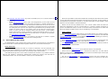
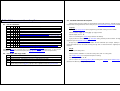
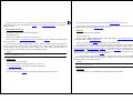
DS100 Serial Device Server
Technical Manual*
Tibbo
Thank you for taking an interest in Tibbo’s Products!
TECHNOLOGY
Always check for updates!
Our every Product is an “ongoing Project”. Basing on our Customer’s feedback we are constantly
working on improving and enhancing the DS100 Serial Device Server. Chances are, the User’s Manual you
are reading now is outdated. Visit our website at www.tibbo.com for up-to-the-minute firmware, software,
and documentation. You can also subscribe to our periodic e-mail newsletter to stay informed on the latest
developments at Tibbo Technology.
The DS100 can be customized in many ways. Have an idea? Let us know now!
Is this Manual for you?
This User’s Manual was designed to serve as a reference for Software Developers and System
Integrators seeking in-depth information on the DS100 functionality and programming. If you are an Enduser with a task to connect your serial device to the network then you most probably should turn to our
Connectivity Manual. This Manual is a user-level document that details the installation, setup, and use of the
DS100 Serial Device Server and Tibbo Device Server Toolkit software ( including Virtual Serial Port Driver).
This Manual assumes that the Reader is a technical specialist with a knowledge of Ethernet and
TCP/IP networking
Is your firmware up to date?
Please, register at www.tibbo.com to receive update notifications
Version: 2.2a
Tibbo Technology, Inc. 2001, 2002
* Formerly User’s Manual
e-mail: [email protected]
tel: 08-52 400 700 fax: 08-520 18121
This Manual describes the functionality of the DS100 Serial Device Server running V2.2x firmware. If
your DS100 has an older firmware you need to upgrade to this new firmware first. See Firmware Download
Mode for a complete information on how to upgrade the DS100.
3
4
Seeking further assistance
If you cannot find an answer to your question or problem you are encouraged to send us an e-mail:
•
[email protected] for technical problems
•
[email protected] for your suggestions
•
[email protected] for sales inquiries
•
[email protected] for all “other” inquiries
Table of Contents
1.
2.
3.
How to print out this Manual
This Manual is supplied in two forms: screen-optimized and print-optimized. Use the screen-optimized
document (DS100 Technical Manual) to conveniently view the Manual on your PC screen. Use the printoptimized version of the above (DS100 Technical Manual (print)) to make a hardcopy of the Manual. The
printed version arranges 2 small document pages per single A4 sheet.
4.
5.
6.
7.
8.
9.
Introduction
1.1.
What is the DS100?
1.2.
Three basic ways of using the DS100
Controls, operating modes, and signals
2.1.
DS100 connectors and controls
2.2.
Operating modes
2.3.
Summary of Status LED signals
Operation in the Normal Mode
3.1.
General information
3.2.
Slave and Master routing modes
3.3.
Serial!Ethernet data routing
3.4.
Buffer-related issues
Programming the DS100
4.1.
General information
4.2.
Serial Programming Mode
4.3.
Network Programming
Available commands and replies
5.1.
List or commands
5.2.
List of possible reply codes
5.3.
Detailed Command description
Available Settings
6.1.
List of Settings by groups
6.2.
Detailed Setting description
Available Parameters
7.1.
List of Parameters
7.2.
Detailed Parameter description
Firmware Download Mode
8.1.
Downloading new firmware file
8.2.
Initializing the DS100
8.3.
Possible download problems and LED signaling
I/O Connector pin assignment & Cable wiring
9.1.
DS100 I/O connector pin assignment
6
6
6
7
7
8
8
Error! Bookmark not defined.
9
11
15
18
19
19
20
22
25
25
25
26
32
32
33
44
44
44
46
46
48
49
50
50
5
9.2.
RS232 cable wiring
9.3.
Ethernet cable wiring
10.Specifications, packing & ordering Information
10.1. Specifications & packing information
10.2. Ordering Information
50
51
52
52
52
1. Introduction
1.1. What is the DS100?
The DS100 is a Serial Device Server. The main function of the DS100 is to network-enable existing
serial devices. Using the DS100 you can connect practically any serial device with RS232 interface to an
Ethernet Local Area Network (LAN). You can then communicate with your serial device from any PC (or
other device) connected to your LAN. And if your LAN has a direct connection to the Internet, then you can
*
access and control your serial device from anywhere in the world !
1.2. Three basic ways of using the DS100
•
If you have a serial device and an existing PC software to control it then you can use the
DS100 in conjunction with our Virtual Serial Port Driver (VSPD). Virtual Serial Ports (VSPs) created
by the driver are logical COMs that behave like standard hardware COMs but in reality
transparently reroute the data via the TCP/IP network to the DS100 and the serial device attached
to it. By using the VSPs you can continue using your existing PC software without any modification.
•
If you have a serial device and are creating a new PC software to control it then you can
communicate with the DS100 directly (without VSPD). The DS100 transmits the data using
industry-standard UDP/IP and TCP/IP communications protocols. Most software development
packages like Visual Basic from Microsoft® provide an easy to use components that simplify
exchanging data with the DS100. Turn to our tutorial Using VB to communicate with the
DS100/EM100 for more information
•
If you have two serial devices that you want to link over the network you can use two DS100s at
both sides to create a Virtual Serial Link over the TCP/IP network.
For more information on how to use the DS100 with different kinds of serial devices please turn to our
Connectivity Manual.
* Provided that you have assigned a valid “true” IP-address to the DS100. “True” IP-address is the address that is unique Internet-wide.
2. Controls, operating modes, and signals
8
2.2. Operating modes
The DS100 has three modes of operation:
2.1. DS100 connectors and controls
•
Normal Mode is entered after the DS100 is powered up with neither Setup Button pressed. It is in
the Normal Mode that the DS100 performs its Ethernet"!Serial data routing. Network
Programming of the DS100 can also proceed in the Normal Mode in parallel with the data routing
•
Serial Programming Mode is entered when either Setup Button is pressed or escape sequence is
sent into the DS100’s serial port while the DS100 is in the Normal Mode. This mode is used to
program the DS100’s functioning parameters (Settings) via the serial port
•
Firmware download mode is entered when the DS100 is powered up with either Setup Button
pressed. This mode is used to download new firmware file into the DS100.
Setup Buttons
Status LEDs
Power Jack
Ethernet LEDs
10BaseT port
2.3. Summary of Status LED signals
RS232 port
•
Setup Buttons. Pressing either button while the DS100 is in the Normal Mode forces the DS100
into the Serial Programming Mode. Powering the DS100 up with either button pressed puts the
DS100 into the Firmware Download mode.
•
Status LEDs indicate DS100’s operating mode/conditions. See Summary of Status LED signals
•
Power Jack- use DC12V, 200mA (min.) power adaptor
•
Ethernet Status LEDs- Green LED blinks when the data packet is received, Red LED indicates
network data collision error
•
Ethernet (10BaseT) port- connects to the LAN
•
Serial (RS232) port- connects to the serial device. This port is also used for DS100 setup in the
Serial Programming Mode and to download new firmware in the Firmware Download Mode.
This Section details the Status LED signaling for the Normal and Serial Programming Modes. LED
signaling in the Firmware Download Mode is detailed in Possible download problems and LED signaling.
Entering the Normal Mode
Setting error, cannot enter the Normal mode
In the Normal Mode:
• Slave Routing Mode
• Master Routing Mode
• Destination IP-address is not reachable*
• Destination IP-address is reachable*
When buffer overflow is detected
In the Serial Programming mode
Red and Green LEDs blink 3 times
Red LED is blinking constantly (Initialize the DS100)
Green LED is constantly on
Green LED is blinking
Green LED is constantly on
Red LED blinks momentarily
Green and Red LEDs are blinking (Green-Red-Green...)
*The DS100 is constantly sending pings to the Destination IP-address when in the Master Routing
Mode (once in every 5 seconds). The Green Status LED is blinking if no reply is received. The Green Status
LED is constantly on when the destination replies to pings.
3. DS100 operation (Normal Mode)
3.1. General information
The main function of the DS100 is to route the data between its Ethernet and serial ports. Routing
means that the data received into the serial port is sent out via the Ethernet port and vise versa. Data routing
is effected through two routing buffers, one for each routing direction.
The DS100 performs the routing in the Normal Mode of operation. A number of user-programmable
Settings and Parameters define the way the DS100 works in the Normal Mode. Settings define permanent
functionality of the DS100 and are programmed into the DS100 via its serial port in the Serial Programming
Mode or via the network in the Network Programming Session. Parameters are temporary overrides for
certain Settings. Parameters can be changed via the network only. For more information see Programming
the DS100.
Ethernet port and network communications
The Ethernet port of the DS100 is of 10BaseT type. Just like any other Ethernet device each DS100 has
a unique Ethernet (MAC) Address and must be assigned a valid IP-address to function properly on the
network.
Logically, the DS100’s network interface has two ports. A user-definable Data Port is used to exchange
the data between the DS100 and other stations on the network. Another port called Command Port has a
fixed number 65535 (FFFF Hex) and is used to send programming commands to the DS100’s over the
network.
The DS100 can exchange data with remote stations using the UDP/IP or TCP/IP transport protocols as
defined by the Transport Protocol Setting. Depending on the Routing Mode Setting the DS100 can act as a
network Slave or Master (see Slave and Master routing modes for details).
10
Other network-related settings include Destination IP-address, Destination Data Port Number, Gateway
IP-address, Netmask, and Connection Timeout (see Available Settings for a complete description of all
Settings).
Besides UDP and TCP protocols used for data transmission the DS100 also supports ARP and ICMP
(ping) protocols. You can ping the DS100 just like any other device on the TCP/IP network.
Serial port
The serial port of the DS100 supports TX, RX, CTS, and RTS signals and can work at baudrates up to
115200. In the Normal Mode the serial port transmits the data between the DS100 and attached serial
device. In the Serial Programming Mode the port is used to program the DS100’s Settings.
Settings that define the operation of the serial port include the Baudrate (150~115200bps), Parity (none,
even, or odd), Bits Per Byte (7 or 8), and Flow Control (none or CTS/RTS). Each of these Settings has a
matching Parameter that overrides the value of a corresponding Setting. (see Available Settings for a
complete description of all Settings).
Routing buffer
The data between the Ethernet port and the serial port is routed via two independent 255-byte buffers,
one for each routing direction. Buffers are necessary because the Ethernet and the serial port operate at
different speeds and in different ways. Ethernet carries the data in “packets” (i.e. groups of data), while the
serial port sends and receives a serial “stream” where each data byte is independent. Here is how the
DS100 transforms the Ethernet packets into the serial stream and back:
•
Ethernet !serial data routing is simple: the DS100 outputs the contents of arriving Ethernet data
packets byte by byte via the serial port. The DS100 does not check of filter the contents of data
being routed in the Ethernet!serial direction
•
Serial !Ethernet routing requires grouping arriving serial data into packets and is more
complicated. Several Settings define exactly what serial data is accepted into the buffer and when
11
12
and how this data is combined into an Ethernet packet and sent out. Detailed information on the
subject can be found in Serial!Ethernet data routing.
virtual serial link over the TCP/IP network. Both sides of the link have DS100s pointing at each
other. The link must work as a plain serial cable and this means that both DS100 must be in the
Master Routing Mode.
3.2. Slave and Master routing modes
The DS100 routes the data in one of two modes as defined by the Routing Mode Setting:
•
In the Slave Routing Mode the DS100 never sends any data transmission in the serial port!
Ethernet direction before it receives some data from the remote station first (i.e. the data in the
Ethernet!serial direction). The serial data received into the DS100’s serial port before the remote
station “contacts” the DS100 is discarded. In the Slave Mode the DS100 will “work” with any station
on the network that contacts it;
•
In the Master Routing Mode the DS100 does not wait for the remote station to send the data first
and routes the data in the serial!Ethernet direction as soon as there is a data to be sent. The data
is always sent to a specific destination (as defined by the Destination IP-address and Destination
Data Port Number Settings of the DS100). Also, the DS100 only accepts the data sent from the
remote station whose IP-address matches the one set in the Destination IP-address. The DS100
will discard the data sent from any other IP. Note, that data port number of the sender is not verified
so the data can be sent from any port.
When to use the Slave and Master Routing Modes
•
Use the Slave Routing Mode to network-enable serial devices that never send out the data by
themselves but instead are “polled” for data from the PC. Examples of such devices are time
recorders, access control panels and other “hardware terminals”.
•
Use the Master Routing Mode to network-enable serial devices that send out the data
“spontaneously” i.e. without waiting for the request from PC. Examples of such devices are barcode
scanners and other “readers” that just output the data after each successful read.
•
Also use the Master Routing Mode in cases when the serial data must flow independently in both
directions (i.e. Ethernet!serial and serial!Ethernet). This is the case when you are creating a
Required network settings for the Slave and Master Routing Modes
•
In the Slave Routing Mode the DS100 only “responds” to other stations on the network. When the
DS100 receives the data from remote station it memorizes this station’s IP-address and data port
number. When routing the data in the serial!Ethernet direction the DS100 will reply to this IPaddress and data port number. Therefore, the only network settings that must be set in the Slave
Routing Mode are the DS100’s own IP-address and the Data Port Number. This is true even if
there is a router between the remote station and the DS100. You don’t have to set the Netmask
and Gateway IP when using the DS100 in the Slave Routing Mode;
•
In the Master Routing Mode the DS100 needs to be able to send the data to a predefined remote
station at any time. This means that not only DS100’s own IP-address and Data Port Number must
be set but also the Destination IP-address and the Destination Data Port Number. If the destination
remote station and the DS100 are residing in different network segments then the Netmask and
Gateway IP-address must also be set.
Slave and Master routing modes vs. UDP/IP and TCP/IP transport protocols
UDP/IP and TCP/IP provide completely different data transmission so DS100s behavior in the Slave
and Master Routing Modes is slightly different under UDP/IP and TCP/IP Transport Protocols.
•
UDP/IP Transport Protocol
o
Slave Routing Mode. All UDP data packets arriving from any remote station and addressed to
the Data Port of the DS100 are routed to the serial port. For the serial!Ethernet direction the
DS100 always sends the data to the IP-address and the port number that were received in the
last (latest) UDP packet. Once the DS100 receives a UDP packet from a different station it will
start sending all its serial!Ethernet data to this new station. After power up and before the
13
14
DS100 receives the first UDP data packet the DS100 doesn’t have any IP-address and port
number to send the data to so all the data received into the DS100’s serial port is simply
discarded.
o
•
Master Routing Mode. The DS100 only accepts and routes to the serial port the data packets
that have originated from the remote station whose IP-address matches the one defined by the
Destination IP-address Setting. Source data port number need not match the one defined by
the Destination Data Port Number Setting so the packet can be sent from any port. Whenever
the DS100 has the data to transmit in the serial!Ethernet direction it will send the data to the
Destination IP-address and Destination Data Port Number. The packet will be sent to the
Destination Data Port Number even if the packet received by the DS100 from the remote
station originated at a different port. Therefore, it possible that the DS100 will be receiving the
data from one port but sending it to another port!
TCP/IP Transport Protocol
o
o
UDP/IP there will never be a situation when the DS100 receives the data from one port but
sends the data to another port. Once the TCP/IP connection has been established both sides
exchange the data using a single port on each side.
Connections with more than two nodes
In many real-life situations it is often necessary to have several PCs (network stations) access the same
serial device through the DS100 (“many clients to one data source”) or have many serial devices (each
connected to the network via its own DS100) send the data to a single PC (“many data sources to one
client”).
An example of “many clients to one source” installation is a hardware terminal or sensor that can be
polled for data from many PCs on the network. A typical “many sources to one client” situation is when
several barcode scanners must send the data to a single PC on the network.
•
Slave Routing Mode. The DS100 will accept an incoming TCP connection from any station on
the network. The DS100 will not attempt to establish a connection with a remote station by
itself even it the DS100 has the data to transmit in the serial!Ethernet direction. Once the
remote station has established the connection the data can flow independently in either
direction. Pending serial!Ethernet data received by the DS100 prior to the TCP connection
establishment is discarded when the connection is established.
Master Routing Mode. The DS100 will both accept an incoming TCP/IP connection and
attempt to establish a connection with the remote station by itself depending on which side
sends that data first- remote station or attached serial device. Incoming TCP connection will
only be accepted from a station whose IP-address matches the one defined by the Destination
IP-address Setting of the DS100. Source port number need not match the one defined by the
Destination Data Port Number Setting so the connection can be initiated from any port. When
the DS100 needs to initiate a TCP/IP connection the it will attempt to connect to the
Destination IP-address and Destination Data Port Number. Once the connection has been
established the data can flow independently in either direction. Note that unlike in case of
•
Many clients to one data source operation is achieved by using the DS100 in the Slave Routing
Mode. The DS100 will reply to any sender in this mode, so any station will be able to access the
serial device attached to the DS100.
o
UDP/IP Transport Protocol should not be used if there is a chance that several different
clients will send the requests to the same DS100/serial device at the same time. Data mix up
will result on the serial side and the DS100 won’t be able to route the data back to the
respective sender of each command correctly.
o
TCP/IP Transport Protocol can be used safely since when one client is already connected to
the DS100 others won’t be able to gain access to the same DS100 until this client disconnects.
To prevent one client from holding the TCP/IP connection to the DS100 indefinitely there is a
Connection Timeout Setting that defines after how long the DS100 will abort the connection in
case there is no data transfer in any direction.
Many data sources to one client operation is achieved by using the DS100 in the Master Routing
Mode. In this mode the DS100 will route all its serial!Ethernet data to the Destination IP-address
15
and Destination Data Port Number. Any number of DS100s can be set to send the data to the
same destination.
o
o
UDP/IP Transport Protocol can be used in this arrangement but you must make sure that
each serial data block output by the serial device (for instance, a complete barcode from a
barcode scanner) is sent out in a single UDP packet. Potential data mix up can occur on the
receiving end if the serial data block is transmitted in several UDP packets and several DS100
are sending data at the same time. The upside of using the UDP/IP is that you will only need to
maintain one listening socket on the receiving end to get the data from all data sources
(unless, of course, you want to distinguish between the data sources). Several DS100’s
Settings define how the incoming serial data is combined into Ethernet packets so you can
make sure that the serial data block from your serial device is not split into several packets
(see serial!Ethernet data routing for details).
TCP/IP Transport Protocol can be used safely but you will have to maintain a separate
socket on the receiving end for every data source sending the data.
3.3. Serial!Ethernet data routing
The DS100 provides a way to choose which incoming serial data is accepted into the serial!Ethernet
buffer, how this data is combined into Ethernet packets and when it is sent out via the Ethernet port.
Serial data blocks
The DS100 treats all incoming serial data as a sequence of data blocks. The term “data block” here
does not mean that the DS100 is only capable of working with a structured serial data. An absolutely
random serial stream can also be processed- as one continuous infinite serial data block.
Serial data blocks begin when a start condition is detected and end when a stop condition is detected.
After the start condition is detected the DS100 begins recording the incoming serial data into the
serial!Ethernet buffer. Thus, the start condition is said to open the serial data block.
16
When the stop condition is detected the DS100 seizes recording the data into the buffer and attempts to
send out all the data accumulated in the buffer via the Ethernet port. Therefore, the stop condition closes the
serial data block. The inter-block serial data i.e. the data received after the stop condition is detected and
before the next start condition is detected is discarded.
Besides the start and stop conditions there is also a break condition. When the break condition is
detected the DS100 doesn’t close the serial data block (i.e. it continues recording subsequent serial data
into the serial!Ethernet buffer) but sends out the data already accumulated in the buffer through the
Ethernet port. Break conditions provide a way to subdivide large serial data blocks.
Start conditions
The Start On Any Character Setting defines if the DS100 recognizes any character received into the
serial port as a start condition or requires a predefined Start Character to open the serial data block. When
Start On Any Character is set to “yes” the DS100 will accept any character following the end of the previous
serial data block as the beginning of the next block.
When Start On Any Character is set to “no” the DS100 will only open the serial data block when one of
the preset Start Characters is received. Up to three different Start Characters can be defined.
Start Characters received after the serial data block has been opened are treated as normal characters
and do not “restart” the serial data block.
Stop conditions
Up to three different Stop Characters can be defined to close the serial data block.
Once one of the preset Stop Characters is detected the DS100 closes the serial data block and
attempts to send out the contents of the serial!Ethernet buffer via the Ethernet port. All subsequent serial
data is ignored until the next start condition is met.
The use of Start Characters and Stop Characters assumes that these characters will not be
encountered in the data block body. Some communications protocols use checksums (or other forms of data
17
integrity verification). Checksum can potentially take any value and occasionally match the ASCII codes of
the Stop Characters. To avoid possible confusion some communications protocols put the checksum bytes
behind the Stop Characters. The DS100 deals with this by allowing to define a Number Of Post-characters
for each enabled Stop Character. For example, if the Number Of Post-characters for a certain Stop
Character is set to 2 then the DS100 will additionally receive and count as belonging to the current serial
data block 2 bytes of data after this Stop Character has been encountered.
18
exchanges the data with PC using command-reply communications protocol. In this situation every time the
hardware terminal finishes transmitting a reply to the PC it starts waiting for the next command to process.
This creates a gap in the serial data coming into the DS100’s serial buffer. After a small delay of 10ms the
DS100 routes the (end of) reply to the PC. The 10ms delay slows a system down a little bit but is, in fact,
negligible for most serial applications.
3.4. Buffer-related issues
Break conditions
The Maximum Data Length Setting defines the maximum number of data bytes in the serial!Ethernet
buffer. (can be set between 32 and 255). Once this number is reached the DS100 attempts to send out the
contents of the buffer via the Ethernet port. This Setting only works when the UDP/IP Transport Protocol is
selected. This is because TCP/IP has its own way to determine what size of data chunks is best for
transmission over the network.
When using the DS100 be careful not to overflow its internal Ethernet!serial and serial!Ethernet
buffers. The overflow can occur because of the difference in receive/transmission speeds on the Ethernet
and the serial sides of the DS100 (Red Status LED blinks momentarily when overflow happens). In addition,
the internal receiving buffer of the attached serial device can potentially overflow if the DS100 outputs the
serial data too fast.
•
The Maximum Intercharacter Delay Setting defines the maximum time gap between the arrival of two
consecutive serial characters into the serial port (can be defined in 10ms increments between 10ms and
2.55 sec). Once this time is exceeded the DS100 attempt to send out the contents of the serial!Ethernet
buffer via the Ethernet port. Setting the Maximum Intercharacter Delay to 0 disables the function.
Default start/stop/break configuration
By default (i.e. after the Initialization) the DS100 is configured to handle a random data stream that
doesn’t have any structure. To achieve this the Start On Any Character is set to “yes”, no Stop Characters
are defined, the Maximum Intercharacter Delay is set to 10ms, and the Maximum Data Length is set to 255
bytes (the latter is needed only for the UDP/IP Transport Protocol). As a result the very first byte received
into the serial port is regarded as a beginning of the serial data block that never ends. Once there amount of
data in the serial!Ethernet buffer reaches the limit or there is a gap in the serial transmission the DS100
combines all serial data it has already received and sends it out.
Practice shows that this arrangement works very well not only for a random data flow but also for
structured data. Consider, for example, a case in which a hardware terminal attached to the DS100
Ethernet!Serial buffer
o
UDP/IP Transport Protocol. The Ethernet!serial buffer can easily overflow because the
Ethernet is much faster than the serial port and UDP/IP has no inbuilt protection against buffer
overflows. UDP/IP should not be used to send continuous data flow and is only suitable for
sending short data blocks that can fit in the buffer.
o
TCP/IP Transport Protocol has an inbuilt protection from buffer overflowing. You can safely
send the data of any size.
•
Serial!Ethernet buffer. The only way to protect the buffer is to enable the RTS/CTS Flow Control
in the DS100 and on the attached serial device. This way the DS100 will be able to signal the serial
device to stop transmitting the data once the buffer becomes full.
•
Internal receiving buffer of the attached serial device. This buffer can also be protected by
using the RTS/CTS to regulate the exchange of data between the DS100 and the serial device.
Using TCP/IP and RTS/CTS is the most reliable way of transmitting data through the DS100
4. Programming the DS100
20
•
Certain commands can only be executed through the network. Some commands have different
result when executed in the Serial Programming Mode and through the network (Initialize
command)
•
Serial Programming Mode can always be entered, even when the DS100 is not properly setup and
needs to be Initialized. Network Programming can only be used when the DS100 is already
functional.
4.1. General information
Settings and Parameters
The operation of the DS100 in the Normal Mode is controlled by a number of user-definable Settings
and Parameters:
•
•
Settings define the permanent functionality of the DS100. Settings are stored in the non-volatile
memory and are preserved even when the DS100 is switched off. After having been changed new
Setting values take effect only after the DS100 is restarted (rebooted)
Parameters are temporary overrides for certain Settings. Changing Parameters have an immediate
effect on the DS100 operation. Parameters are preserved only until the DS100 is switched off or
restarted.
Ways of programming the DS100
The DS100 can be programmed in two different ways:
•
Through the serial port of the DS100 in a Serial Programming Mode
•
Over the network using UDP packets sent to a command port 65535 (FFFF Hex). This method is
called Network Programming
Groups of commands
The DS100 is programmed using programming commands that fall into three categories:
•
Setup commands are used to program the Settings of the DS100. Setup commands can be
issued both in the Serial Programming Mode and using the Network Programming, in a so-called
Network Setup Session.
•
Parameter commands are used to change the Parameters. These commands can only be sent
over the network.
•
Broadcast commands are sent in the Ethernet broadcast mode and are used for automatic
discovery of the DS100s on the network and over-the-network assignment of new IP-addresses.
Naturally, the Broadcast commands can only be sent over the network.
See Available commands and replies for a complete description of all commands.
4.2. Serial Programming Mode
There are several differences between the Serial Programming Mode and the Network Programming:
•
Serial Programming Mode is a separate mode of operation. The DS100 is not performing its data
routing function when in the Serial Programming Mode. In contrast the Network Programming is not
a separate mode of operation but a method of programming. Network Programming can proceed in
parallel with the normal operation of the DS100.
Serial Programming Mode is a separate mode of operation that can only be used to edit Settings (via
Setup commands). Parameter commands and Broadcast commands cannot be issued in the Serial
Programming Mode.
Serial Programming is effected by sending commands to and receiving replies from the DS100’s serial
port.
21
Entering the Serial Programming Mode
There are two ways of entering the Serial Programming Mode:
•
•
By pressing either Setup Button while in the Normal Mode. This forces the DS100 to enter the
Serial Programming Mode with default communications parameters of 38400-8-N-1, flow
control=”none”.
By sending an escape sequence of three consecutive SOH (ASCII code 1) characters to the
serial port (“soft entry”). The Soft Entry Setting of the DS100 defines if escape sequence will
work. Soft Entry is disabled by default. Escape characters must be sent at a current baudrate.
When entering the Serial Programming Mode through escape sequence the DS100 preserves the
current baudrate, defined by the Baudrate Setting. However, the parity is still set to “none”, number
of bits- to 8, and the flow control- to “none” regardless of the values of Parity, Bits Per Byte, and
Flow Control Settings.
The state of the RTS (output) line of the DS100 must be ignored when in the Serial Programming Mode.
Therefore, you must disable the flow control on your PC (if you use PC to setup the DS100) or in the
attached serial device (if the serial device does the programming) for the duration of the Serial Programming
Mode.
Exiting Serial Programming Mode
22
STX (ASCII code 2) and CR (ASCII code 13) provide necessary encapsulation. Command code field
always consists of one character (i.e. “S”, “G”, etc.). Setting name and Setting value fields are only
required for certain commands. Setting name always consists of two characters (i.e. “BR”, “SA”, etc.).
Setting value format depends on the type of Setting.
All replies returned by the DS100 in the Serial Programming Mode have the following format:
STX (2)
Reply code
Setting value (if any)
CR (13)
Reply code is always present and informs you of the command processing status (OK, failed, etc.).
Setting value field is only present for commands that return Setting values.
4.3. Network Programming
Setup commands, Parameter commands, and Broadcast commands can all be sent over the network.
Parameter commands and Broadcast commands can be sent at any time. Executing Setup commands
requires a Network Setup Session to be opened first.
Network programming is effected by sending commands to and receiving replies from the command
port (65535 or FFFF Hex) of the DS100. Each command and reply must be sent in its own UDP packet.
Opening Network Setup Session (Login)
You can exit the Serial Programming Mode either by switching the DS100 off and back on again or by
using the Exit command. In both cases the DS100 restarts operation using the new Setting values.
The Network Setup Session is opened by logging in using a Login command. Correct password
matching that defined by the Login Password Setting must be supplied. Login command must be used even
if the Login Password is set to NUILL (default after the Initialization).
Serial command and reply format
All commands sent to the DS100 in the Serial Programming Mode must have the following format:
STX (2)
Command code
Setting name (if any)
Setting value (if any)
CR (13)
If you forgot the password you can use the Serial Programming Mode to set a new password since the
Serial Programming Mode is not password-protected.
23
Closing Network Setup Session
Network Setup Session is closed either by switching the DS100 off and back on again or by using an
Exit command. In both cases the DS100 restarts operation using the new Setting values.
Command and reply format for Setup and Parameter commands
The format of Setup and Parameter Commands and replies sent via the network is similar to that of
Setup commands and replies exchanged in the Serial Programming Mode with the only exception that STX
and CR characters are not required- sending each command and reply in a separate UDP packet provides a
necessary encapsulation already.
Setup and Parameter Commands have the following format:
Command code
Setting/Parameter name
Setting/Parameter value
Command code field always consists of one character (i.e. “S”, “G”, etc.). Setting/Parameter name
field and Setting/Parameter value fields are optional and only required for certain commands. Name
always consists of two characters (i.e. “BR”, “SA”, etc.). Value format depends on the type of
Setting/Immediate.
All replies sent by the DS100 over the network have the following format:
Reply code
Setting/Parameter value
Reply code field is always present and informs you of the command processing status (OK, failed,
etc.). Setting/Parameter value field is only present for replies that return values.
Format of Broadcast commands
Broadcast commands have no unified format. Format of each Broadcast command and corresponding
reply is described in Available commands.
24
5. Available commands and replies
Command and reply strings below are shown without STX and CR characters. STX/CR encapsulation is
required when sending commands via the serial port (see Serial command and reply format for details).
5.1. List or commands
Code S N B L
Setup commands
L
+
S
+ +
+
G
+ +
+
I
+ +
+
E
+ +
+
V
+ +
Parameter commands
P
+
Broadcast commands
X
+ +
A
+ +
26
5.3. Detailed Command description
Description
Login (L)
Login (open Network Setup Session)
Set (write) new Setting value
Get (read) current Setting value
Initialize (restore Settings to their default factory values)
Exit Serial Programming Mode/Network Setup Session (restart the DS100)
Get firmware version
Opens Network Setup Session for the programming of DS100’s Settings over the network
Command format: “Lppp…p”, where ppp…p- login password
Possible replies: “A”, “F”, “D”
Can be issued through the network only (broadcast not allowed)
Change Parameter value
Login password is defined by the Login Password Setting. Default password is NULL but login is still
required to open the Network Setup Session.
Request echo from all listening DS100s
Assign new IP-address to the DS100 with the specified Ethernet address
F reply may happen because of the DS100’s internal malfunction (for example, inability to retrieve
current password from the non-volatile memory). D reply code is returned when the supplied password is
incorrect.
Columns: “S”- command is available in the Serial Programming mode; “N” -command can be issued
through the network; “B”- command can be issued through the network in broadcast mode; “L”- when issued
through the network this command requires prior login (Network Setup Session must be opened first).
Set (S)
5.2. List of possible reply codes
Command format: “Snnvvv…v”, where nn- Setting name, vvv…v- Setting value
Code
A
C
F
D
Description
Completed successfully, may be followed by data (if this command returns data)
Invalid command, Setting/Parameter name, or Setting/Parameter value
Command execution failed (internal error or malfunction)
Access denied. This reply code can only be sent in response to a network command. It
means that you haven’t logged in properly or have supplied an incorrect Login Password.
Set (write) new Setting value
See Available Settings for a complete description of Settings
Possible replies: “A”, “C”, “F”, “D”
Can be issued in the Serial Programming Mode or through the network in the Network Setup Session
(broadcast not allowed, prior login required)
27
C reply code is returned if the Setting name is incorrect or new Setting value is invalid (out of range, has
invalid formatting, etc.). F reply may happen because of the DS100’s internal malfunction (for example,
failure to save new Setting value into the non-volatile memory). D reply code is returned when command is
issued through the network and the Network Setup Session is not opened (i.e. without prior login).
Example. Set the IP-address of the DS100 to “192.168.100.40”:
SIP192.168.100.40
A
Get (G)
Get (read) current Setting value
Command format: “Gnn”, where nn- Setting name
See Available Settings for a complete description of Settings
Possible replies: “Avvv…v”, “C”, “F”, ”D”, where vvv…v- Setting value
Can be issued in the Serial Programming Mode or through the network in the Network Setup Session
(broadcast not allowed, prior login required)
C reply code is returned if the Setting name is incorrect. F reply is returned when current Setting value
is invalid or could not be retrieved (situation can be rectified by setting correct value using the Set command
or using the Initialize command to restore all Settings to their default factory values). D reply code is
returned when command is issued through the network and the Network Setup Session is not opened (i.e.
without prior login).
Example. Get the IP-address of the DS100:
GIP
A192.168.100.40
28
Initialize (I)
Initializes the DS100 (restores all Settings to their default factory values)
Command format: “I”
Possible replies: “A”, “F”, ”D”
Can be issued in the Serial Programming Mode or through the network in the Network Setup Session
(broadcast not allowed, prior login required)
This command performs the following: (1) all Settings are restored to their default values with the
following exceptions: (a) Factory Ethernet address is not initialized (because it contains unique address set
by the factory), and (b) IP-address and Current Ethernet Address of the DS100 is not initialized in case this
command is issued through the network; (2) in case the command is issued in the Serial Programming
Mode the value of the Factory Ethernet address Setting is copied into the Current Ethernet address Setting.
If this command fails (F reply code), this maybe because the Factory Ethernet address Setting contains
invalid value. In this case initialize it first by setting any address you can think of (i.e. “204.134.165.0.44.55”)
but make sure that the first number is even, then try to use the Initialize command again. D reply code is
returned when command is issued through the network and the Network Setup Session is not opened (i.e.
without prior login).
Exit (E)
Exits the Serial Programming Mode or Network Setup Session, also restarts the DS100 which puts new
Setting values into effect
Command format: “E”
Possible replies: no reply in case of success, “D”
Can be issued in the Serial Programming Mode or through the network in the Network Setup Session
(broadcast not allowed, prior login required)
29
No reply is returned in case of successful execution because the DS100 restarts. D reply code is
returned when command is issued through the network and the Network Setup Session is not opened (i.e.
without prior login).
Get firmware version (V)
Gets firmware version of the currently loaded firmware
Command format: “V”
Possible replies: “Avvv…v”, where vvv…v - version string
Can be issued in the Serial Programming Mode or through the network (broadcast not allowed, prior
login is not required)
The version string is always encapsulated in “<” and “>” characters, begins with the version number in
the “X.XX” format and possibly contains a small comment after a space. Version numbering follows this
system: change in the first digit- major release, change in the second digit- new minor features or
alterations, change in the third digit- bug fixes but no functionality changes.
Example:
V
A<V2.20 RELEASE2 final>
Parameter (P)
Changes Parameters of the DS100
Command format: “Pppv”, where pp- parameter, v- value if any
See Available Parameters for a complete description of Parameters
30
The DS100 only accepts Parameter command when the Remote Control is set to “yes”.
C reply code is returned if supplied parameter name or value is incorrect. D reply code is returned if
command is rejected because the Remote Control is set to “no”.
Echo (X)
Request Echo from all listening DS100s
Command format: “X”
Possible replies: “Aether_addr/port_num”, where ether_addr is Current Ethernet Address of the
DS100, port_num- current Data Port Number
Can be issued through the network only (broadcast mode should be used)
This command can be utilized to auto-detect all the DS100s on a local network segment. When sent in
the broadcast mode it reaches all locally attached DS100s. Each DS100 then replies with its Current
Ethernet Address and Data Port Number (IP-address is not returned because it is already contained in the
IP-packet’s header). Reply will reach the sender even when the IP-address of the DS100 is not valid.
Ethernet address of each particular DS100 is needed for an over-the-network assignment of the new IPaddress to the designated DS100 using the Assign command.
It is noteworthy that broadcast packets cannot penetrate routers, bridges, etc. and, therefore, are
confined to a local network segment. Consequently, it is impossible to use this command to discover the
DS100s outside the local network segment.
Example:
X
A192.168.100.40/1001
Possible replies: “A”,”C”,”D”
Assign (A)
Can be issued through the network only (broadcast not allowed, prior login not required)
Assign new IP-address to the DS100 with the specified Ethernet (MAC) address
31
Command format: “Aether_addr/password/ip_addr”, where ether_addr- Ethernet (MAC) address of
the DS100 that is to be assigned a new IP-address, password- Login Password for this DS100, ip_addrnew IP-address to be assigned.
Possible replies: this command is never replied to
Can be issued through the network only (broadcast mode should be used)
This command is used to assign a new IP-address to the DS100 with specific Ethernet (MAC) address.
When sent in the broadcast mode this command reaches all locally attached DS100s. Only the DS100
whose Current Ethernet Address matches that in the ether_addr field of the command will change its IPaddress to ip-addr value (provided that correct Login Password has been supplied in the password field).
This command is never replied to but its result can be verified using Echo command.
This command is useful when you need to assign a valid IP-address to the uninitialized DS100. Using
the Set command to change the IP-address Setting of the DS100 is not possible at this time since executing
this command requires the DS100 to have a valid IP-address already. Having to supply a valid password is
usually not an issue since uninitialized (ex-factory) DS100 have a NULL password.
It is noteworthy that broadcast packets cannot penetrate routers, bridges, etc. and, therefore, are
confined to a local network segment. Consequently, it is impossible to assign a new IP-address using this
command to the DS100s outside the local network segment.
Example: set the IP-address of the DS100 whose Ethernet address is 0.1.2.3.4.5 and login password is
“pwd1” to 192.168.100.40
A0.1.2.3.4.5/pwd1/192.168.100.40
6. Available Settings
6.1. List of Settings by groups
The following is a complete list of all available Settings. Setting values are set and retrieved using Set
and Get commands:
Code
RM
IP
DI
PN
DP
TP
CT
GI
NM
PW
BR
PR
BB
FC
RC
SE
ML
MD
Description
Network-related Settings
Routing mode (slave/master)
IP-address of the DS100
Destination IP-address. Only relevant in the Master Routing Mode
Data Port Number of the DS100 (0…65534)
Destination Data Port Number (0…65535). Only relevant in the Master Routing Mode
Transport Protocol (UDP/TCP)
Connection Timeout (never/1…255min). Only relevant with TCP Transport Protocol
Gateway IP-address. Only relevant in the Master Routing Mode
Netmask. Only relevant in the Master Routing Mode
Login Password for the Network Setup Session
Serial port-related Settings
Baudrate (150/300/1200/2400/4800/9600/19200/38400/57600/115200bps)
Parity (none/even/odd)
Bits Per Byte (7/8)
Flow Control (none/RTS-CTS)
Remote Control of DS100’s Parameters via Parameter Commands (enable/disable)
Soft Entry (by escape sequence) into the Serial Programming Mode (enable/disable)
Serial!Ethernet routing Settings
Maximum Data Length (32…255bytes). Only relevant with UDP Transport Protocol
Maximum Intercharacter Delay (disabled/10…2550ms)
33
SA
F1, F2, F3
S1, S2, S3
U1, U2, U3
E1, E2, E3
P1, P2, P3
EA
FE
SI
Start On Any Character (no/yes)
Start Characters, Enable/Disable. Not relevant when Start On Any Character= “yes”
Start Characters, ASCII code. Not relevant when Start On Any Character= “yes”
Stop characters, Enable/Disable
Stop characters, ASCII code
Stop characters, Number Of Post-characters
System Settings
Current Ethernet (MAC) address
Factory (default) Ethernet (MAC) address
Serial Interface (full-duplex/half-duplex/auto)
34
Default: 127.0.0.1
See also: Ethernet port and network communications
Destination IP-address (DI)
Defines the Destination IP-address. Only relevant in the Master Routing Mode
Set command format: “SDIip_addr”, where ip_addr must be in the dot-decimal format, i.e.
“192.168.100.40”
Get command format: “GDI”
Default: 127.0.0.2
6.2. Detailed Setting description
Routing Mode (RM)
Selects Slave or Master Routing Mode
Set command format: “SRMx”, where x- 0- Slave Routing Mode, 1- Master Routing Mode
Get command format: “GRM”
Default: 0 (Slave)
See also: ---
IP-address (IP)
Defines own IP-address of the DS100
Set command format: “SIPip_addr”, where ip_addr must be in the “dot-decimal” format, i.e.
“192.168.100.40”
Get command format: “GIP”
See also: Ethernet port and network communications
Data Port Number
Defines own data port number for the DS100
Set command format: “SPNport_num”, where port_num must be in the 0…65534 range
Get command format: “GPN”
Default: 1001
Port number 65535 cannot be used since it is reserved for a command port.
See also: Ethernet port and network communications
Destination Data Port Number
Defines the destination data port number. Only relevant in the Master Routing Mode
Set command format: “SDPport_num”, where port_num must be in the 0…65535 range
35
36
Get command format: “GDP”
Gateway IP-address (GI)
Default: 1001
Defines the IP-address of the default gateway. Only relevant in the Master Routing Mode
See also: Ethernet port and network communications
Transport Protocol (TP)
Selects UDP/IP or TCP/IP communications protocol for data transmission
Set command format: “STPt”, where t- 0- UDP/IP protocol, 1- TCP/IP protocol
Get command format: “GTP”
Default: 0 (UDP/IP)
See also: Ethernet port and network communications, Slave and Master routing modes vs. UDP/IP and
TCP/IP transport protocols, Buffer-related issues
Connection Timeout (CT)
Specifies timeout (in minutes) for the TCP/IP connection in case no data is transmitted in any direction
Set command format: “SCTtout”, where tout is the connection timeout in minutes (0-255). Value of 0
disables this function (connection never times out)
Get command format: “GCT”
Default: 5 (5 minutes)
When no data is exchanged across the TCP/IP connection for a specified number of minutes the DS100
will abort the connection automatically (by sending a RESET packet). This Setting prevents an idle client
(connection) from “holding” the DS100 indefinitely.
See also: Ethernet port and network communications, Connections with more than two nodes (many
clients to one data source under TCP/IP Transport Protocol)
Set command format: “SIPgateway_ip”, where gateway_ip must be in the “dot-decimal” format, i.e.
“192.168.100.40”
Get command format: “GGI”
Default: 127.0.0.1
Defines the IP-address of the default gateway to which the DS100 sends the data in case the
Destination IP-address is not on the local network segment. Whether the Destination IP-address is local or
not is defined by the Netmask Setting.
See also: Ethernet port and network communications
Netmask (NM)
Defines the IP-address range for the local network segment. Only relevant in the Master Routing Mode
Set command format: “SNMnetmask”, where netmask must be in the “dot-decimal” format, i.e.
“255.255.255.0”
Get command format: “GNM”
Default: 0.0.0.0 (any Destination IP-address is considered to be local)
The Netmask defines whether the Destination IP-address is considered to be on the local network
segment or foreign network segment. In the latter case the DS100 sends the data to the default Gateway IPaddress rather then to the Destination IP-address directly.
See also: Ethernet port and network communications
37
Login Password (PW)
Defines login password for the Network Setup Session
Set command format: “SPWpassword”, where password is the login password (0-6 characters long,
valid characters are those with ASCII codes in the 32…127 range).
Get command format: “GPW”
Default: NULL
You need to Login even when the password is set to NULL (i.e. password has a zero length).
See also: ---
Baudrate (BR)
Sets the baudrate of the DS100’s serial port. Can be overridden by the Baudrate Parameter.
Set command format: “SBRb”, where b: 0-.1200bps, 1- 2400bps, 2- 4800bps, 3- 9600bps, 419220bps, 5- 38400bps, 6- 57600bps, 7- 115200bps, 8- 150bps, 9- 300bps, 10- 600bps
Get command format: “GBR”
Default: 5 (38400bps)
See also: ---
Parity (PR)
Selects the parity mode of the DS100’s serial port. Can be overridden by the Parity Parameter.
Set command format: “SPRp”, where p: 0-.Disabled, 1- Even, 2- Odd
Get command format: “GPR”
Default: 0 (Disabled)
38
See also: ---
Bits Per Byte (BB)
Defines the bits/byte mode of the DS100’s serial port. Can be overridden by the Bits Per Byte
Parameter.
Set command format: “SBBb”, where b: 0-.7 bits/byte, 1- 8 bits/byte
Get command format: “GBB”
Default: 1 (8 bits/byte)
See also: ---
Flow Control (FC)
Selects the flow control mode for the DS100’s serial port. Can be overridden by the Flow Control
Parameter.
Set command format: “SFCf”, where f: 0-.none, 1- RTS/CTS (hardware)
Get command format: “GFC”
Default: 0 (none)
You are recommended to choose the RTS/CTS flow control whenever possible
See also: Buffer-related issues
Remote Control (RC)
Enables/Disables DS100’s Parameter changing through the Parameter command
Set command format: “SRCp”, where p: 0-.Disabled, 1- Enabled
Get command format: “GRC”
39
Default: 1 (Enabled)
See also: ---
40
Set command format: “SMDdel”, where del is the maximum intercharacter delay (0-255). Value of 0
disables this function. Actual delay is calculated as del X 10ms, i.e. it can be in the 10-2550ms range.
Get command format: “GMD”
Soft Entry (SE)
Enables/disables entry into the Serial Programming Mode by escape sequence
Default: 1 (10 ms)
See also: Serial!Ethernet data routing (Break conditions)
Set command format: “SSEs”, where s: 0-.Disabled, 1- Enabled
Get command format: “GSE”
Default: 0 (Disabled)
See also: ---
Maximum Data Length (ML)
Defines the amount of data in the serial!Ethernet buffer at which the break condition will be generated
and the contents of the buffer will be sent out via the Ethernet port. Only relevant when the UDP/IP
Transport Protocol is selected
Start On Any Character (SA)
Defines if the next serial data block is opened on any character received or only when one of predefined Start Characters is received
Set command format: “SSAs”, where s: 0- No (new serial data block is opened on predefined Start
Characters only), 1- Yes (new serial data block is opened on any character)
Get command format: “GSA”
Default: 1 (Yes)
See also: Serial!Ethernet data routing (Start conditions)
Set command format: “SMLlen”, where len is the length of data in bytes (32-255)
Get command format: “GML”
Default: 255
See also: Serial!Ethernet data routing (Break conditions)
Maximum Intercharacter Delay (MD)
Defines the time gap after the arrival of the most recent serial character into the serial port which, when
exceeded, leads to a break condition and makes the DS100 send out the contents of the serial!Ethernet
buffer via the Ethernet port
Start Character, Enable/Disable (F1, F2, F3)
Three separate Settings to enable/disable start characters 1, 2, and 3 (ASCII codes of start characters
are defined by Start character, ASCII Code Settings). Not relevant when Start On Any Character is set to
“yes”
Set command format: “SF1e”, “SF2e”, “SF3e”, where e: 0- Disabled, 1- Enabled
Get command format: “GF1”, “GF2”, “GF3”
Default: 0 (Disabled)
See also: Serial!Ethernet data routing (Start conditions)
41
Start Character, ASCII Code (S1, S2, S3)
Three separate Settings to define the ASCII codes of start characters 1, 2, and 3 (start characters are
enabled/disabled through Start Character, Enable/Disable Settings). Not relevant when Start On Any
Character is set to “yes”
Set command format: “SS1c”, “SS2c”, “SS3c”, where c is an ASCII code of the start character (0-255)
Get command format: “GS1”, “GS2”, “GS3”
Default: 0
See also: Serial!Ethernet data routing (Start conditions)
Stop Character, Enable/Disable (U1, U2, U3)
Three separate Settings to enable/disable stop characters 1, 2, and 3 (ASCII code of stop characters
are defined by Stop character, ASCII Code Settings)
Set command format: “SU1e”, “SU2e”, “SU3e”, where e: 0- Disabled, 1- Enabled
Get command format: “GU1”, “GU2”, “GU3”
Default: 0 (Disabled)
See also: Serial!Ethernet data routing (Stop conditions)
Stop Character, ASCII Code (E1, E2, E3)
Three separate Settings to define the ASCII codes of stop characters 1, 2, and 3 (stop characters are
enabled/disabled through Stop character, Enable/Disable Settings)
Set command format: “SE1c”, “SE2c”, “SE3c”, where c is an ASCII code of the stop character (0-255)
Get command format: “GE1”, “GE2”, “GE3”
Default: 0
42
See also: Serial!Ethernet data routing (Stop conditions)
Stop Character, Number of Post Characters (P1, P2, P3)
Three separate Settings to define the number of post characters to follow stop characters 1, 2, and 3
(ASCII codes of stop characters are defined by Stop character, ASCII Code Settings, stop characters are
enabled/disabled through Stop character, Enable/Disable Settings)
Set command format: “SP1n”, “SP2n”, “SP3n”, where n in a number of Post-characters (0-255)
Get command format: “GP1”, “GP2”, “GP3”
Default: 0
See also: Serial!Ethernet data routing (Stop conditions)
Current Ethernet Address (EA)
Defines current Ethernet (MAC) address of the DS100
Set command format: “SEAe_addr”, where e_addr must be in the “dot-decimal” format, i.e.
“100.101.102.103.104.105”.
Get command format: “GEA”.
Default: copied from the Factory Ethernet address Setting
This Ethernet address is used by the DS100 during operation.
See also: Initialize (I)
Factory Ethernet Address (FE)
Keeps default Ethernet address
Set command format: “SFEe_addr”, where e_addr must be in the “dot-decimal” format, i.e. “1.2.3.4.5.6”
43
Get command format: “GFE”
Default: unique number for each DS100 produced
This Setting contains a default Ethernet address assigned to a particular DS100 during production.
Tibbo Technology initializes each DS100 to different Ethernet address number. You are advised to never
change it. If you want to change the Ethernet address of the DS100 do this by changing the value of the
Current Ethernet Address Setting. During the Initialization, the value of this Setting is copied into the Current
Ethernet Address thus restoring factory Ethernet address for use.
See also: Initialize
Serial Interface (SI)
Selects full-duplex or half-duplex mode for serial interface
7. Available Parameters
7.1. List of Parameters
The following is a complete list of all available Parameters. Parameters are set using Parameter
command:
Name
BR
PR
BB
FC
Description
Baudrate (150/300/1200/2400/4800/9600/19200/38400/57600/115200bps)
Parity (none/even/odd)
Bits Per Byte (7/8)
Flow Control (none/RTS-CTS)
7.2. Detailed Parameter description
Set command format: “SSIi”, where i: 0- RS232, 1- RS485, 2- Auto
Get command format: “GSI”
Default: 2 (Auto)
For the DS100 to operate properly, always keep this Setting at “Auto” (as selected by default)
Baudrate (BR)
Changes current baudrate of the DS100’s serial port. This Parameter overrides the Baudrate Setting
Command format: “PBRb”, where b: 0-.1200bps, 1- 2400bps, 2- 4800bps, 3- 9600bps, 4- 19220bps, 538400bps, 6- 57600bps, 7- 115200bps, 8- 150bps, 9- 300bps, 10- 600bps
See also: ---
Parity (PR)
Changes current parity mode of the DS100’s serial port. This Parameter overrides the Parity Setting
Command format: “PPRp”, where p: 0-.Disabled, 1- Even, 2- Odd
See also: ---
45
Bits Per Byte (BB)
Changes current bits/byte mode of the DS100’s serial port. This Parameter overrides the Bits Per Byte
Setting
Command format: “PBBb”, where b: 0-.7 bits/byte, 1- 8 bits/byte
See also: ---
Flow Control (FC)
8. Firmware Download Mode
Internal firmware of the DS100 can be upgraded in the field. We are constantly working on the DS100
functionality enhancement, so new firmware versions are released quite often. New firmware versions are
posted at www.tibbo.com. You are advised to register at our site so we can let you know when the new
firmware becomes available.
Red Status LED is blinking after you have downloaded new firmware and the DS100 doesn’t
seem to work? You have forgotten to initialize the DS100!
Changes current flow control mode of the serial port. This Parameter overrides the Flow Control Setting
Command format: “PFCf”, where f: 0-.none, 1- RTS/CTS
8.1. Downloading new firmware file
See also: ---
New firmware file is downloaded into the DS100 through its RS232 port. To download the firmware file
you’ll need any PC software that supports an XMODEM communications protocol (checksum version).
Suitable software packages are Term95 (part of a Norton Commander package), QMODEM (a very popular
DOS program), and a HyperTerminal. The latter is especially widespread because it comes with every
Windows distribution. Procedures below assume the use of HyperTerminal for Windows.
The HyperTerminal is normally found in the Start! Programs! Accessories! Communications!
HyperTerminal folder. If it is not there, then you must have opted it out when installing Windows on your PC.
Follow the instructions below to add HyperTerminal to your system (be sure to have your Windows
distribution CD handy!):
•
Go to the Control Panel (Start! Settings! Control Panel) and double-click on the
Add/Remove Programs icon- the Add/Remove Programs dialog will open
•
Click on Windows Setup tab to view the list of optional installation components
•
Choose Communications in the Components list and click Details
•
In the Communications window, select the HyperTerminal (it must be “checked”)
•
Press OK to close Communications window, press OK again to close Add/Remove Programs
47
•
48
You will possibly be asked to insert the Windows CD at this point. Do this and follow the
instructions on the screen.
Once the HyperTerminal is installed, follow the procedures below to download new firmware file into the
DS100:
•
Switch the DS100 off
•
Connect the DS100’s Serial port to the PC using WAS-1455 or similar cable
•
Launch the HyperTerminal and configure it as follows:
o
When the Connection Description dialog opens, type any descriptive string (like
“DS100”) and press OK
o
When the Connect to dialog opens, select an appropriate COM port from the Connect
Using drop-down box (for example, “Direct to COM1”)
o
When the COM Properties dialog appears, set communications parameters as
follows: Bits per second: 38400, Data bits: 8, Parity: None, Stop bits: 1, Flow control:
None. Click OK when done- the HyperTerminal’s main window will appear
o
Now choose File!Properties from the Main menu- the Properties dialog will appear
o
Click on the Settings tab and press the ASCII Setup button- the ASCII Setup dialog
will open
o
Check (enable) three options: Echo typed characters locally, Send line feeds with line
ends, and Append line feeds to incoming line ends
o
Click OK twice to close both dialogs
o
Optional: you may want to save this HyperTerminal configuration for the future use.
This way you won’t have to go through this elaborate setup again next time. Choose
File!Save from the Main menu to save this configuration under the filename you’ve
chosen for your connection
•
Choose Transfer! Send file from the Main menu- the Send file dialog will appear
•
In the Send file dialog, select the firmware file that you want to download into the DS100 and
choose the Xmodem protocol from the Protocol drop-down box. Click OK when finished
•
The Xmodem file send for a dialog will be displayed
•
Press either Setup Button on the back of the DS100 and power the DS100 up while keeping
the Button pressed- the download will start. You may release the Button at this point
•
DS100’s Green Status LED is blinking during the download, and the HyperTerminal shows the
file transfer progress
•
When the download is finished, switch the DS100 off and back on again. If the Red Status LED
starts blinking this means that the DS100’s Settings need to be initialized. Do not exit the
HyperTerminal and proceed to the next Section for further instructions
8.2. Initializing the DS100
Initialize command is used to initialize the DS100 after the new firmware download.
#I
#A
•
Make sure the DS100 is powered up and press either Setup Button. The DS100 will enter the
Serial Programming Mode
•
In the HyperTerminal window type <CTRL+B> followed by capital “I” and press <ENTER> key.
Pressing <CTRL+B> sends an STX character (appears on the HyperTerminal’s screen as a
“smiley face”) while pressing <ENTER> sends CR character (see Serial command and reply
format for more information)
•
The DS100 should reply with STX-“A”-CR which means that command was completed
successfully. The whole dialog should look like this:
49
•
Switch the DS100 off and back on again- the DS100 should start normal operation.
9. I/O Connector pin assignment & Cable wiring
8.3. Possible download problems and LED signaling
9.1. DS100 I/O connector pin assignment
A number of errors can occur when downloading new firmware file. All errors are expressed as Red
Status LED signals (“blinking patterns”):
The DS100 has one 10BaseT (Ethernet) port and one RS232 (Serial) port. Pin assignment is shown in
the table below:
One long signal
One long + one short signal
One long + two short signals
One long + three short signals
Timeout while waiting for the data from PC
Communications error (XMODEM error)
File is too big and cannot fit in the DS100s memory
DS100 program memory (FLASH) failure
Every time you power the DS100 up its internal firmware is checked for being valid. If the firmware is
valid, the DS100 starts normal operation. If the firmware you have downloaded is not valid then one of the
following may occur:
•
If you’ve been downloading a correct firmware file but the download wasn’t finished, then the
DS100 will blink its Red and Green Status LEDs rapidly
•
If you’ve downloaded a wrong file, then the DS100 will not show “any signs of life” on startup.
In both cases, make sure you are trying to download correct firmware file and repeat the downloading
process.
To avoid common confusion, all pins are designated as inputs and outputs with respect to the DS100.
RS232M (Serial) port
9
5
10BaseT (Ethernet) port
6
1
#1
#2
#3
#4
#5
#6
#7
#8
No connection
RX (Input)
TX (Output)
No connection
Ground
No connection
RTS (Output)
CTS (Input)
#9
No connection
8
#1
#2
#3
#4
#5
#6
#7
#8
1
TX+
TXRX+
No connection
No connection
RXNo connection
No connection
9.2. RS232 cable wiring
There are two kinds of RS232 cable suitable for use with the DS100: DS100-to-Device (WAS-1404) and
DS100-to-PC (WAS-1455). You can use your own cable in case the standard one is not suitable. Cable
wiring is presented in the table below:
51
DS100-to-Device (WAS-1404)
DB9M (Male)
DB9F (Female)
#2 "
! #2
! #3
#3 "
! #5
#5 "
! #7
#7 "
#8 "
! #8
DS100-to-PC (WAS-1455)
DB9F (Female)
DB9F (Female)
#2 "
! #3
! #2
#3 "
! #5
#5 "
! #8
#7 "
#8 "
! #7
Important note: you need to have a DS100-to-PC cable to be able to download new firmware.
9.3. Ethernet cable wiring
Most Ethernet installations require cables of substantial and variable length, so you will probably need
to make your own cables. For testing purposes Tibbo supplies two kinds of Ethernet cables: device-to-hub
(WAS-1499) for connections through a standard Ethernet hub, and device-to-device (WAS-1498) for
connections without a hub (i.e. directly from one Ethernet device to another).
Device-to-hub (WAS-1499)
Side A
Side B
#1 " (*)
#2 " (*)
#3 " (**)
#4 "
#5 "
#6 " (**)
#7 "
#8 "
! #1
! #2
! #3
! #4
! #5
! #6
! #7
! #8
Device-to-device (WAS-1498)
Side A
Side B
(*) #1, #2
must share
the same
twisted pair;
(**) #3, #6
must share
the same
twisted pair;
#1 " (*)
#2 " (*)
#3 " (**)
#4 "
#5 "
#6 " (**)
#7 "
#8 "
! #3
! #6
! #1
! #4
! #5
! #2
! #7
! #8
10. Specifications, packing & ordering Information
10.1. Specifications & packing information
Ethernet interface:
Serial interface:
Network Protocols
Data buffers
Power supply:
Operation Temperature
Operating relative humidity
Unit dimensions (including connectors)
Carton dimensions (DS100R/ DS100R-KIT)
Gross weight (DS100R/ DS100R-KIT)
10BaseT Ethernet
RS232, DB9M, signals: RX, TX, RTS, CTS, Ground
UDP, TCP, ICMP (ping), ARP
Two independent 255-byte buffers (for Ethernet!serial and serial!Ethernet
data transmission
DC 12V, 150mA
0-55 Co
10-90%
95mm(L) x 57mm(W) x 30mm(H)
130mm(L) x 100mm(W) x 65mm(H)/ 325mm(L) x 145mm(W) x 90mm(H)
950g/ 170g
10.2. Ordering Information
DS100RDS100R-E-KIT
DS100R-U-KIT
ARP-1014
ARP-1015A
WAS-1455
WAS-1404
WAS-1499
WAS-1498
DSK-T0001
Bare DS100 in the individual carton (no accessories included except a Velcro sticker for wall mounting)
DS100 with accessories: ARP-1014 (110V), WAS-1455, WAS-1404, WAS-1499, WAS-1498, DSK-T001
Same as the above but with the ARP-1015A (220V) power adaptor
AC 110V/ DC 12V power adaptor
AC 220V/ DC12V power adaptor
DS100-to-PC RS232 180cm cable (required for firmware downloading!)
DS100-to-Device RS232 140cm cable
Device-to-hub Ethernet 180cm cable
Device-to-device Ethernet 180cm cable
Official CD with all the latest documentation and software