1
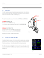
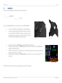
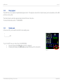
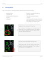
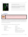
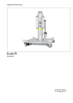
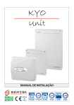
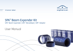
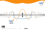
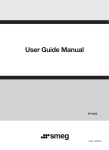
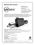
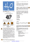
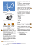
HUDC-Manual Vers: 1.3 HUDC – User Manual Head Up Dive Computer Vers: 1.3 Mar. 2014 Contact details [email protected] Seabear Diving Technology, Seabear GmbH, Austria © 2014 Seabear Diving Technology - Graz - Austria Page 1 of 49 HUDC-Manual Vers: 1.3 Table of Contents 1 Introduction ............................................................................................................................................................................. 5 2 Safety considerations ............................................................................................................................................................. 6 3 Warnings - cautions - notes .................................................................................................................................................... 7 3.1 Warnings ............................................................................................................................................................................ 7 3.2 NOTICE .............................................................................................................................................................................. 9 4 Mounting the device.............................................................................................................................................................. 10 4.1 Mounting the pressure transmitter.................................................................................................................................... 10 4.2 Mounting the HUDC on a full-face mask .......................................................................................................................... 11 4.3 Mounting the HUDC on a second stage regulator............................................................................................................ 12 4.4 Adjusting the length of the mounting bracket ................................................................................................................... 12 4.5 Battery .............................................................................................................................................................................. 13 5 Operating interfaces ............................................................................................................................................................. 14 5.1 Control buttons ................................................................................................................................................................. 14 5.2 Activation and deactivation of the HUDC ......................................................................................................................... 14 5.3 Optic and display interface ............................................................................................................................................... 15 5.4 PC interface...................................................................................................................................................................... 15 6 Operating modes .................................................................................................................................................................. 15 6.1 Surface mode display ....................................................................................................................................................... 16 6.2 Dive mode display ............................................................................................................................................................ 17 7 Menus, settings and functions .............................................................................................................................................. 18 7.1 Menu structure ................................................................................................................................................................. 18 7.2 MAIN MENU ..................................................................................................................................................................... 19 7.3 SETTINGS ....................................................................................................................................................................... 19 7.3.1 SET TIME ......................................................................................................................................................................... 20 7.3.2 SET DATE ........................................................................................................................................................................ 21 7.3.3 SET DIVE ......................................................................................................................................................................... 22 7.3.3.1 FO2+/- - adjusting volume fraction of Oxygen content.................................................................................................... 22 7.3.3.2 PSET – personal settings ................................................................................................................................................. 23 7.3.3.3 EXIT ................................................................................................................................................................................. 23 7.3.4 COMPASS ....................................................................................................................................................................... 24 7.3.5 SET UNITS....................................................................................................................................................................... 25 7.3.6 EXIT ................................................................................................................................................................................. 25 © 2014 Seabear Diving Technology - Graz - Austria Page 2 of 49 HUDC-Manual 7.4 USB MODE ...................................................................................................................................................................... 26 7.4.1 Firmware upgrade ............................................................................................................................................................ 27 7.4.2 Diving logbook .................................................................................................................................................................. 28 7.4.3 Standby mode .................................................................................................................................................................. 28 8 Diving with HUDC ................................................................................................................................................................. 29 8.1 Before diving .................................................................................................................................................................... 29 8.2 Dive mode activation ........................................................................................................................................................ 30 8.3 No decompression dives .................................................................................................................................................. 31 8.4 Decompression dives ....................................................................................................................................................... 32 8.5 Nitrox ................................................................................................................................................................................ 35 8.6 Displayed information in dive mode ................................................................................................................................. 37 8.6.1 Remaining no decompression time (NDT) ....................................................................................................................... 37 8.6.2 Tank pressure .................................................................................................................................................................. 37 8.6.3 Ascent/Descent rate bar graph......................................................................................................................................... 38 8.6.4 Battery indicator ............................................................................................................................................................... 39 9 Altitude .................................................................................................................................................................................. 41 9.1 Flying after diving ............................................................................................................................................................. 41 9.2 Altitude diving ................................................................................................................................................................... 41 10 Care and maintenance ......................................................................................................................................................... 42 11 Technical specifications ........................................................................................................................................................ 43 11.1 Intended use..................................................................................................................................................................... 43 11.2 Operating conditions ........................................................................................................................................................ 43 11.3 Operating temperature ..................................................................................................................................................... 43 11.4 Depth gauge ..................................................................................................................................................................... 43 11.5 Tank pressure sensor....................................................................................................................................................... 43 11.6 Temperature measurement .............................................................................................................................................. 44 11.7 Memory ............................................................................................................................................................................ 44 11.8 Logbook............................................................................................................................................................................ 44 11.9 PC interface...................................................................................................................................................................... 44 11.10 Compass .......................................................................................................................................................................... 44 11.11 Battery .............................................................................................................................................................................. 44 11.12 User interface ................................................................................................................................................................... 45 11.13 Mechanical and material characteristics .......................................................................................................................... 45 12 Functional specifications....................................................................................................................................................... 46 12.1 Oxygen concentrations (Nitrox) ........................................................................................................................................ 46 © 2014 Seabear Diving Technology - Graz - Austria Vers: 1.3 Page 3 of 49 HUDC-Manual 12.2 Altitude correction............................................................................................................................................................. 46 12.3 Decompression model...................................................................................................................................................... 46 12.4 Activation / Deactivation ................................................................................................................................................... 46 12.5 Personal settings .............................................................................................................................................................. 46 12.6 Display surface mode ....................................................................................................................................................... 47 12.7 Display dive mode ............................................................................................................................................................ 47 13 Limited warranty ................................................................................................................................................................... 48 14 SEABEAR Limitation of Liability ........................................................................................................................................... 48 © 2014 Seabear Diving Technology - Graz - Austria Vers: 1.3 Page 4 of 49 HUDC-Manual Vers: 1.3 1 Introduction Welcome to Seabear Diving Technology. You have chosen a sophisticated Head Up Dive Computer - a true hands-free dive computer solution of high quality, reliable safety and ease of usability that displays all dive relevant data directly in front of your eye. The Head Up Dive Computer (HUDC) can be mounted on any second stage regulator. With a flexible mounting device you are able to bring the HUDC in an optimal position in front of your half-or full-face mask. The full color display shows you all the necessary dive-related information like tank pressure, current depth, current time, elapsed dive time, water temperature, decompression times, ascent rate, and has a build in tilt-compensated digital compass. The relevant data (depth, time, decompression obligations, tank pressure) are stored in the internal flash memory. The data can be read out via USB port, which is also used to charge the built in rechargeable battery. Fig. 1 The HUDC is a near-eye true hands-free dive computer. Due to the close vicinity of the HUDC to the visor, the HUDC can still be read in very low visibility conditions (e.g. silt out), where reading of a normal wrist worn dive computer is often impossible. Fig. 2 © 2014 Seabear Diving Technology - Graz - Austria Fig. 3 Fig. 4 Page 5 of 49 HUDC-Manual Vers: 1.3 2 Safety considerations Before using the Head Up Dive Computer you must read and understand the information provided in this manual in its entirety. Be aware that diving has many inherent risks. A dive computer considerably increases your diving safety but it does not eliminate the remaining risk for serious injury, or death caused by decompression sickness, Oxygen toxicity or some other inherent risk of scuba diving. Do not use this HUDC if you are not aware of these risks, and you do not accept these remaining risks. In this manual the following precautionary symbols are used to indicate the following important precautionary statements. Those statements , Signalwort-Panel provide information on potential hazards and proper procedures. Three differently safety Signs are used to indicate their importance: red stands for vital information, which shall not be ignored under any circumstances; yellow advises for caution; blue indicates technical or other recommendations for safe and reliable operation of the device: g, Signalwort-Panel nel“ n WARNING statements describe potentially hazardous situations, if not avoided, could result in death, or serious, injury. Avoid these situations under any circumstances. nel“ CAUTION indicates a hazardous situation which, if not avoided, could result in minor or moderate injury. NOTICE statements are used to notify the user of information regarding installation, operation, maintenance, performance, general tips that are important, or statements describing a procedure or situation that might cause damage to the device but is unrelated to physical injury. 15 15 © 2014 Seabear Diving Technology - Graz - Austria Page 6 of 49 HUDC-Manual , Signalwort-Panel 3 Vers: 1.3 Warnings - cautions - notes , Signalwort-Panel 3.1 Warnings nel“ , Signalwort-Panel Before using the HUDC, read the manual and get familiar with all the functions of the device. nel“ Divers must have successfully completed a course in scuba diving. They must have knowledge about the potential risks and hazards of scuba diving. , Signalwort-Panel nel“ , Signalwort-Panel nel“ , Signalwort-Panel nel“ , Signalwort-Panel We strongly recommend diving within the recreational limits, to limit your maximum depth to 40 m and to limit the pO2 to a maximum of 1.4 bar. Exposure to greater depths or pO2 increases the risk of Oxygen toxicity and/or decompression sickness. Diving beyond the recreational limits may greatly increase your risk of decompression 15sickness. Diving should not be undertaken without obtaining the necessary training from a recognized training agency. 15 nel“ , Signalwort-Panel nel“ The risk from decompression sickness (DSC) or Oxygen toxicity for any dive profile, even if you follow dive tables, or a dive computer, cannot be totally eliminated. This risk also depends on the individual diver’s physiological condition, which can vary from day to day. The HUDC cannot account for these variations. We strongly advise you to stay within the exposure limits provided by the instrument to minimize the risk of DCS. Before diving you should consult a physician regarding your fitness to dive. The HUDC is designed for Nitrox with Oxygen content from 20 to 50%. It is NOT designed for mix gas diving. 15 Do not ignore warning signs and indicators on the HUDC, as this may result in serious injuries and can be even lethal. nel“ Be aware of Nitrogen narcosis, this cannot be indicated on this computer, there are no warnings. 15 © 2014 Seabear Diving Technology - Graz - Austria 15 Page 7 of 49 HUDC-Manual Vers: 1.3 , Signalwort-Panel nel“ , Signalwort-Panel nel“ , Signalwort-Panel nel“ , Signalwort-Panel The HUDC can be only used with open circuit breathing systems. The HUDC does not indicate any safety stops. Safety stops must be done according to your own planning, and on your own responsibility. Safety stop shall be made between 6 and 3meters.It is strongly recommended to perform safety stops as a standard procedure before completing your dive. The HUDC should never be shared between differed divers. Use always the same HUDC for repetitive dives. There is an in-built memory that keeps track of a diver’s diving history. Changing the HUDC in between a series of repetitive dives may result in incorrect decompression calculations. nel“ Should the HUDC fail, you should immediately abort the dive by using a diving table or a back up dive computer.. , Signalwort-Panel nel“ , Signalwort-Panel 15 If a reset of the HUDC occurs, for instance, after a software update, information about tissue tensions from previous dives will be lost. When this situation happens in between a series of repetitive dives, the decompression schedule and the remaining 15no decompression time for the following dives may be incorrect. nel“ , Signalwort-Panel Do not fly, or travel to high altitudes while the NO-FLY indication remains active. Flying while the HUDC displays NO FLY can result in serious injury or death. nel“ 15 nel“ 15 , Signalwort-Panel nel“ If you do not perform the proposed decompression stops, a flashing sign will indicate a ceiling to which you should ascend. If you still ignore these warnings, there is NO additional ERROR OR LOCKOUT. Do not ignore these warnings, decompression stops must be done for your own safety and on your own responsibility. For safety reasons you should always dive with backup instruments, including a depth gauge, pressure gauge, dive watch, or a backup dive computer and have access to decompression tables while planning your dive with the HUDC. If you do not fully understand how to use the HUDC, or if you have any questions, contact your instructor, or your Seabear Diving Technology dealer before diving with it. 15authorized © 2014 Seabear Diving Technology - Graz - Austria Page 8 of 49 HUDC-Manual 3.2 Vers: 1.3 NOTICE Never lift or carry your cylinder by holding the pressure transmitter. If there is a mechanical shock on the pressure transmitter, (e.g. if your cylinder falls on the side with the pressure transmitter attached to the first stage of the regulator), ensure that the pressure transmitter is not damaged. Ensure that there is no water or moisture inside the device, as well as in the high-pressure port (HP). This may seriously damage the unit. Do not disassemble or remodel any cable or connectors. Use only the original USB cable, supplied with the HUDC. Check compatibility before use. Use only a clean, and dry USB cable. Clean and dry the connector surfaces of the cable, as well as the connector on the HUDC before each use to prevent damage of the HUDC, in particular to avoid corrosion of the USB connector contacts. © 2014 Seabear Diving Technology - Graz - Austria Page 9 of 49 HUDC-Manual 4 Vers: 1.3 Mounting the device 4.1 Mounting the pressure transmitter The pressure transmitter contains a tank pressure sensor and the battery. To mount the pressure transmitter, first, remove the high-pressure port plug from the first stage regulator. Then screw in the pressure transmitter gently by hand until you feel a minimum of resistance. Use a suitable tool (wrench) to tighten it. Fig. 5 Fig. 6 Fig. 7 g, Signalwort-Panel n Do not twist the pressure transmitter forcefully by hand. Use a proper tool to tighten the pressure transmitter (Fig.8). nel“ Always close the tank pressure valve and depressurize your regulator before attempting to remove or connect the HUDC to the high-pressure port. Fig. 8 © 2014 Seabear Diving Technology - Graz - Austria Page 10 of 49 HUDC-Manual 4.2 Vers: 1.3 Mounting the HUDC on a full-face mask clamp ball joints The mounting bracket for the HUDC consists of an adapter, several ball joints and a clamp. adapter ENTGRATEN UND SCHARFE KANTEN BRECHEN WENN NICHT ANDERS DEFINIERT: OBERFLÄCHENGÜTE: BEMASSUNGEN SIND IN MILLIMETER OBERFLÄCHENBESCHAFFENHEIT: TOLERANZEN: LINEAR: WINKEL: Fig. 9 NAME SIGNATUR DATUM ZEICHNUNG NICHT SKALIEREN ÄNDERUNG BENENNUNG: GEZEICHNET 21 11 01 9 8 7 6 5 GEPRÜFT 4 GENEHMIGT 3 2 1 PRODUKTION hose_Assem1_1 WERKSTOFF: QUALITÄT ZEICHNUNGSNR: GEWICHT: A MASSSTAB:1:1 A Disconnect the low-pressure hose from the second stage regulator and slide the adapter over the thread of the regulator (Fig.11). B B Reconnect the low-pressure hose to the thread of the second stage regulator. Use a suitable tool (wrench) to tighten it (Fig. 10). C C D Fig. 11 D Fig. 10 E E F F Slide the HUDC in the clamp (Fig.12) and adjust the mounting bracket in a way that the display is comfortably placed in front of your visor. G G GNUREDNÄ NETARGTNE EFRAHCS DNU NETNAK NEHCERB NEREILAKS THCIN GNUNHCIEZ :ETÜGNEHCÄLFREBO MUTAD :GNUNNENEB A2 BLATT 1 VON 1 :TREINIFED SREDNA THCIN NNEW RETEMILLIM NI DNIS NEGNUSSAMSEB :TIEHNEFFAHCSEBNEHCÄLFREBO :NEZNARELOT :RAENIL :LEKNIW RUTANGIS EMAN TENHCIEZEG H TFÜRPEG Fig. 12 TGIMHENEG NOITKUDORP 2A 1_1messA_esoh .RNSGNUNHCIEZ 1 NOV 1 TTALB © 2014 Seabear Diving Technology - Graz - Austria 1:1:BATSSSAM :FFOTSKREW :THCIWEG TÄTILAUQ 8 7 6 5 4 3 2 1 Page 11 of 49 HUDC-Manual Vers: 1.3 Adjust the ball joints of the mounting bracket in a comfortable position, so that the screen falls in the field of your vision once the mask is properly donned. A slight readjustment underwater might be necessary to account for the optical diffraction index of water. The HUDC is compatible with many models of a full-face masks (Fig.13, 14). 4.3 Fig. 14 Fig. 13 Mounting the HUDC on a second stage regulator The assembly is done in the same way as the assembly of the HUDC on a full-face mask. There is no limitation on the type of the second stage regulator for mounting the device (Fig.15). Fig. 15 4.4 Adjusting the length of the mounting bracket The length of the mounting bracket can be adjusted by removing or adding some ball joints (Fig.16, 17). You have to exert little force to remove a ball joint or to snap them together. Do not use lubrication on the ball joints. ENTGRATEN UND SCHARFE KANTEN BRECHEN WENN NICHT ANDERS DEFINIERT: OBERFLÄCHENGÜTE: BEMASSUNGEN SIND IN MILLIMETER OBERFLÄCHENBESCHAFFENHEIT: TOLERANZEN: LINEAR: WINKEL: NAME SIGNATUR OBERFLÄCHENBESCHAFFENHEIT: BENENNUNG: TOLERANZEN: LINEAR: WINKEL: GEZEICHNET GEPRÜFT NAME GENEHMIGT GEPRÜFT hose_A WERKSTOFF: GENEHMIGT ZEICHNUNGSNR: GEWICHT: MASSSTAB:1:1 PRODUKTION QUALITÄT Fig. 16 © 2014 Seabear Diving Technology - Graz - Austria Fig. 17 SIGNATUR GEZEICHNET PRODUKTION QUALITÄT ZEICHNUNG NICHT SKAL WENN NICHT ANDERS DEFINIERT: OBERFLÄ BEMASSUNGEN SIND IN MILLIMETER DATUM Page 12 of 49 HUDC-Manual Vers: 1.3 4.5 Battery The HUDC is equipped with a rechargeable Lithium-ion battery. The battery is charged over the USB in approximately 8 hours. Before your fist dive recharge the battery. Use the original HUDC USB interface cable and slide it in the socket of the HUDC as shown in Fig.18. Make sure to position the plug correctly into the socket in order to ensure good electric connection. A fully charged battery will last for approximately 25 diving hours. The condition and the charging level of the battery are indicated with a small battery symbol, appearing on the display. Additionally, the battery voltage is displayed on the surface in mV. A well-charged battery has about 3800 to 4150 mV. The battery symbol changes its color from green over yellow to red, and flashing red according to the battery discharge level. It is recommended to recharge the HUDC if the battery symbol is yellow or red. If the voltage decreases to low level, the battery symbol will flash red, and the HUDC will shut off in a short period of time. Fig. 18 The battery has a lifetime of approximately 500 charging cycles, which is typical for Lithium-ion batteries. If you need to replace the battery, please, contact your authorized Seabear Diving Technology service provider to replace it. © 2014 Seabear Diving Technology - Graz - Austria Page 13 of 49 HUDC-Manual 5 Vers: 1.3 Operating interfaces 5.1 Control buttons The HUDC is operated by means of two integrated piezo switches/buttons. These buttons are used to turn on and off the HUDC, and to navigate through the menu. The two buttons are located on the TOP and the right SIDE of the HUDC (Fig.19). TOP button Throughout this manual the buttons will be referred to as the TOP button and SIDE button. SIDE button TOP button= NEXT MENU ITEM This button is located on TOP of the housing. The TOP button is used to activate the menu and to switch to the NEXT MENU ITEM. SIDE button= SELECT MENU ITEM This button is located on the opposite SIDE of the USB connector. The SIDE button is used to select the DISPLAYED MENU ITEM. Fig. 19 Keep this logic in mind when navigating through the menu! 5.2 Activation and deactivation of the HUDC To switch on the device press one of the two buttons. After the welcome screen, the display shows the surface mode screen allowing you to navigate within the menu with the two buttons. The buttons are only active in surface mode. Underwater the buttons are deactivated. The HUDC switches off automatically after some minutes, if the diver is on the surface, and the tank pressure is less than 15 bar. Alternatively, it is possible to switch off the HUDC manually, see chapter 7.2. Fig. 20 © 2014 Seabear Diving Technology - Graz - Austria Page 14 of 49 HUDC-Manual Vers: 1.3 5.3 Optic and display interface The full color OLED display is viewed through a bright optical system. The design of the optical system allows the user to see the image of the display in a virtual distance of one meter from the eye. The display will appear in a virtual dimension of a15-inch monitor in one meter distance. The HUDC display is readable in a wide range of ambient light conditions. Shading may be required only in direct sunlight on the surface. The HUDC is a true hands-free dive computer, and due to the close vicinity to the visor of the diver, it can be read even in very low visibility and silt out situations. 5.4 PC interface The HUDC is equipped with a USB port. The USB charging cable is used to connect the HUDC to a USB port of a personal computer. 6 Operating modes The HUDC has three operating modes: standby- surface- and dive-mode. Standby-mode: The display of the HUDC is switched off, and the microprocessor operates in a power saving state. A fully charged battery lasts up to 1 year in standby mode. Surface-mode: The surface-mode is used to navigate in the menu, to adjust the settings, to activate the USB MODE, and to switch off the HUDC. The surface-mode is activated after switching on the computer with one of the buttons. If the HUDC is not used for 5 minutes, and the pressure transmitter is depressurized, the HUDC switches to standby mode to save battery power. Dive-mode: The dive-mode is automatically activated following immersion in water, and after reaching a depth of one meter. There is a display for a no decompression dive mode, and a display for a decompression dive mode. The HUDC should be switched on the surface. © 2014 Seabear Diving Technology - Graz - Austria Page 15 of 49 HUDC-Manual Vers: 1.3 nel“ Switching the HUDC on underwater may lead to incorrect measurement of the atmospheric pressure on the surface, which may lead to incorrect depth readings, and faulty decompression calculation. 6.1 Surface mode display Alphanumeric display: -‐ Time -‐ Date -‐ FO2 volume fraction of Oxygen content [%O2] -‐ Personal decompression setting 0,1,2,3 -‐ GF gradient factors -‐ Tank pressure[bar / PSI] -‐ Atmospheric/surface pressure [bar / PSI] 15 -‐ Battery [mV] -‐ Menu item Graphical indicators: -‐ Battery indicator[3300 - 4100 mV] -‐ -‐ -‐ -‐ Green zone > 3700 mV Yellow zone 3400 mV to3700mV Red zone < 3400 mV Compass scale Atmospheric/surface pressure Time Battery in mV Date Battery Indicator FO2 volume fraction of Oxygen [%O2] Compass scale Personal decompression setting Menu item Gradient factors Tank pressure © 2014 Seabear Diving Technology - Graz - Austria Fig. 21 Page 16 of 49 HUDC-Manual 6.2 Vers: 1.3 Dive mode display Alphanumeric display: -‐ Maximum depth[m/ft] -‐ Current depth[m/ft] -‐ Dive time [min] -‐ No decompression time indicator -‐ Remaining no decompression time – NDT [min] -‐ Ceiling depth[m/ft] -‐ Time to surface [min] -‐ Compass [0..360°] Tank pressure [bar / PSI] -‐ Temperature [°C / °F] Graphical indicators: -‐ Compass scale -‐ Battery indicator[3300 - 4100 mV] -‐ -‐ -‐ -‐ -‐ -‐ Green zone > 3700 mV Yellow zone 3400 mV to3700mV Red zone < 3400 mV Ascent/descent rate bar graph -‐ -‐ -‐ -‐ Blue zone = Descent rate bar graph Green zone <5m/min Yellow zone 5m/min to 10m/min Red zone 10m/min to 20m/min Tank pressure bar graph -‐ -‐ -‐ -‐ Green zone >110 bar Yellow zone 50 bar to 110 bar Red zone 25 bar to 50 bar Red blinking <25 bar Ceiling indicator Compass in° Maximum depth Battery indicator Current depth NDT indicator Dive time Remaining no decompression time Compass scale Tank pressure graph Time to surface Ascent rate graph Ceiling depth Tank pressure Ceiling indicator Temperature Fig. 22 Display NO decompression dive mode © 2014 Seabear Diving Technology - Graz - Austria Fig. 23Display decompression dive mode Page 17 of 49 HUDC-Manual 7 Vers: 1.3 Menus, settings and functions 7.1 Menu structure I I____________SETTINGS I I I I I I I I I I I I I I I I I I I I I I I I I____________USB MODE I I__________ I I____________OFF I__________ I I I I__________ I I I I I I__________ I I I I I I__________ I I__________ I I I I__________ SET TIME I__________ I__________ HOUR+ MINUTES+ SET DATE I__________YEAR + I__________ YEAR I__________ MONTH+ I__________DAY+ SET DIVE I__________ I__________ I__________ I__________ FO2+ FO2PSET+ EXIT Ø Use the TOP button to activate the menu and switch to the NEXT MENU ITEM. Ø Use the SIDE button to confirm the SELECTED MENU ITEM. COMPASS SET UNITS I__________ I__________ m-bar ft-PSI EXIT EXIT USB The menu can only be used on the surface. © 2014 Seabear Diving Technology - Graz - Austria Page 18 of 49 HUDC-Manual Vers: 1.3 7.2 MAIN MENU The MAIN MENU has three items. I I____________SETTINGS … setting parameters, time, date and calibration of the compass I I____________USB MODE … selecting the USB mode for data access and transfer I I____________OFF … deactivation of the HUDC and entering into standby mode To go to the MAIN MENU you have to be in the surface mode. Ø Pressing and releasing the TOP button will activate the main menu. Ø Repeated pressing and releasing the TOP button will toggle in the MAIN MENU between SETTINGS - USB MODE – OFF. Ø If no button is pressed for a period of 15 seconds, the menu will be deactivated. 7.3 SETTINGS The sub menu SETTINGS has 6 items: I I____________SETTINGS I I I I I I I I I I I I__________ I I__________ I I__________ I I__________ I I__________ I I__________ SET TIME … setting the actual time SET DATE … setting the actual date SET DIVE … setting parameters for diving COMPASS … calibrating the compass SET UNITS … changing between metric and imperial units EXIT … exit the sub menu back to main menu Fig. 24 To go to the SETTINGS menu you have to be in the MAIN MENU. Ø Press and release the TOP button until SETTINGS is displayed. Ø Pressing and releasing the SIDE button will select the menu item SETTINGS. © 2014 Seabear Diving Technology - Graz - Austria Page 19 of 49 HUDC-Manual Ø Ø Vers: 1.3 Repeated pressing and releasing of the TOP button will toggle in the SETTINGS menu between SET TIME - SET DATE - SET DIVE – COMPASS - SET UNITS – EXIT. If no button is pressed for a period of 15 seconds, the menu will be deactivated. 7.3.1 SET TIME The actual time can be set in the sub menu SET Time: I__________ I I SET TIME I__________ I__________ HOUR+ MINUTES+ …stepping up the hour 0-23 …stepping up the minutes 0-59 To go to the SET TIME menu you have to be in the SETTINGS menu. Ø Press and release the TOP button until SET TIME is displayed. Ø Pressing and releasing the SIDE button will select the menu item SET TIME. Fig. 25 Ø Ø Pressing and releasing the SIDE button will select the setting HOUR+. Repeated pressing and releasing the SIDE button will step up the HOUR+ value, continue pressing, and releasing the SIDE button till the right hour is on the display. Ø Ø Press and release the TOP button to switch to the next menu item MINUTES+. Repeated pressing and releasing the SIDE button will step up the MINUTES+ value, continue pressing, and releasing the SIDE button till the right minute is on the display. Ø Press and release the TOP button to EXIT the menu (the SET TIME procedure is finished, there is no further menu item, so the user exits the menu, and the time is stored). © 2014 Seabear Diving Technology - Graz - Austria Page 20 of 49 HUDC-Manual Vers: 1.3 7.3.2 SET DATE The actual date can be set in the sub menu SET DATE: I__________SET DATE I I__________YEAR + I I__________YEAR I I__________MONTH+ I I__________DAY+ …stepping …stepping …stepping …stepping up the year down the year up the month 1-12 up the day 1-31 To go to the SET DATE menu you have to be in the SETTINGS menu. Ø Press and release the TOP button until SET DATE is displayed. Ø Pressing and releasing the SIDE button will select the menu item SET DATE. Fig. 26 Ø Ø Pressing and releasing the SIDE button will select the setting YEAR+. Repeated pressing and releasing the SIDE button will step up the YEAR+ value, continue pressing, and releasing the SIDE button till the right YEAR is on the display. Ø Ø Press and release the TOP button to switch to the next menu item YEAR-. Repeated pressing and releasing the SIDE button will step down the YEAR- value, continue pressing, and releasing the SIDE button till the right YEAR is on the display. Ø Ø Press and release the TOP button to switch to the next menu item MONTH+. Repeated pressing and releasing the SIDE button will step up the MONTH+ value, continue pressing, and releasing the SIDE button till the right MONTH is on the display. Ø Ø Press and release the TOP button to switch to the next menu item DAY+. Repeated pressing and releasing the SIDE button will step up the DAY+ value, continue pressing, and releasing the SIDE Button till the right DAY is on the display. Ø Press and release the TOP button to EXIT the menu (the SET DATE procedure is finished, there is no further menu item, so the user exits the menu, and the date is stored). © 2014 Seabear Diving Technology - Graz - Austria Page 21 of 49 HUDC-Manual Vers: 1.3 7.3.3 SET DIVE The settings for diving can be personalised in the sub menu SET DIVE: I__________ I I I I SET DIVE I__________ I__________ I__________ I__________ FO2+…stepping up the FO2 value 20-50 FO2-…stepping down the FO2 value 20-50 PSET+…stepping up the PSET value 0-3 EXIT…EXIT To go to the SET DIVE menu you have to be in the SETTINGS menu. Ø Press and release the TOP button until SET DIVE is displayed. Ø Pressing and releasing the SIDE button will select the menu item SET DIVE. 7.3.3.1 Fig. 27 FO2+/- - adjusting volume fraction of Oxygen content To increase the setting for the Oxygen fraction in a Nitrox mixture: To go to the FO2+ setting you have to be in the SET DIVE menu. Ø Press and release the TOP button until FO2+ is displayed. Ø Pressing and releasing the SIDE button will step up the FO2+ value, continue pressing, and releasing the SIDE button till the right FO2 is on the display. g, Signalwort-Panel To decrease the setting for the Oxygen fraction in a Nitrox mixture: Ø Press and release the TOP button to switch to the next menu item FO2-. Ø Repeated pressing and releasing the SIDE button will step down the FO2- value, n g, Signalwort-Panelcontinue pressing, and releasing the SIDE button till the right FO2 is on the display. anel“ n Fig. 28 Before each Nitrox dive, the FO2 setting of the dive computer must be verified, and if necessary adjusted to match the fraction (percentage) of O2 in the Nitrox mix being used. anel“ Diving with Nitrox requires special training and Nitrox certification. © 2014 Seabear Diving Technology - Graz - Austria Page 22 of 49 HUDC-Manual 7.3.3.2 Vers: 1.3 PSET – personal settings For additional safety, four personal decompression settings can be set (Eric Baker gradient factors). , Signalwort-Panel PSET 0: GF 30/80 (preset value, typical standard value) PSET 1: GF 15/90 PSET 2: GF 80/80 PSET 3: GF 95/95 (standard ZH-L16C Buehlmann model, with minimum conservatism!) nel“ PSET 3: GF 95/95 Do not use this setting under normal conditions! This setting results in long no decompression limits and aggressive decompression schedules. Use this setting only for emergency purposes. To go to the PSET setting you have to be in the SET DIVE menu. Ø Press and release the TOP button until PSET+ is displayed. Ø Repeated pressing and releasing the SIDE button will toggle the PSET Value between 0 - 1 - 2 - 3. Continue pressing and releasing the SIDE button till the right PSET is on the display. Press and release the TOP button to switch to the next menu item EXIT and save the Ø Ø PSET value. 7.3.3.3 Fig. 29 EXIT 15 To go to the EXIT item you have to be in the SET DIVE menu. Ø Pressing and releasing the SIDE button when EXIT is displayed will deactivate the menu. Fig. 30 © 2014 Seabear Diving Technology - Graz - Austria Page 23 of 49 HUDC-Manual Vers: 1.3 7.3.4 COMPASS During the calibration process the compass adjusts itself to the surrounding magnetic field and to tilting. In the menu COMPAS you can calibrate the compass. I__________ COMPASS To go to the COMPAS calibration you have to be in the SETTINGS menu. Ø Press and release the top button until COMPASS is displayed. Ø Pressing and releasing the SIDE button will select the COMPAS calibration. Ø Start with the calibration process Fig. 31 The calibration of the 3-axial compass requires 3 simple steps (Fig. 32, 33 and 34).During each step the HUDC is rotated around one axis (note the rotation axis in Fig.33 should be horizontal). Rotate the HUDC at least 3 times in each position like depicted in the figures. Test if the compass is working otherwise repeat the calibration. Fig. 32 © 2014 Seabear Diving Technology - Graz - Austria Fig. 33 Fig. 34 Page 24 of 49 HUDC-Manual Vers: 1.3 7.3.5 SET UNITS In the menu SET UNITS the units can be changed from imperial to metric. Temperature: °C / °F Pressure: bar / PSI Length: m / ft I__________ SET UNITS I I I__________ I__________ m-bar ft-PSI To go to the SET UNITS you have to be in the SETTINGS menu. Ø Press and release the TOP button until SET UNITS is displayed. Ø Pressing and releasing the SIDE button will select the SET UNIT item. Ø Repeated pressing and releasing the TOP button will toggle in the SET UNIT m-bar (metric) and ft-PSI (imperial). Ø If you want to set the HUDC to metric mode, press and release the SIDE button when m-bar is displayed. Ø If you want to set the HUDC to imperial mode, press and release the SIDE button when ft-PSI is displayed. Fig. 35 7.3.6 EXIT From the EXIT menu you can exit the menu. I__________ EXIT You can access the EXIT menu from the SETTINGS menu. Ø Pressing and releasing the SIDE button will deactivate the menu. Fig. 36 © 2014 Seabear Diving Technology - Graz - Austria Page 25 of 49 HUDC-Manual Vers: 1.3 7.4 USB MODE In the menu USB Mode the USB interface can be activated. I I____________USB MODE I I__________ EXIT USB To go to the USB MODE menu you have to be in the MAIN MENU. Ø Ø Ø Ø Ø Ø Connect the HUDC to the USB port via the USB cable. Use the original HUDC USB interface cable and slide it into the socket of the HUDC. Please, ensure the correct positioning of the plug into the socket in order to have an electric contact between plug and socket. Fig. 37 Fig. 38 Press and release the TOP button until USB MODE is displayed. Pressing and releasing the SIDE button will select the menu item USB MODE and activate the USB interface. Now the device will be recognized as a mass storage device and can be accessed by any file explorer from a computer. Pressing and releasing the SIDE button will EXIT the menu and switch off the interface. Fig. 39 The USB mode is used for firmware upgrade and to access the logbook. © 2014 Seabear Diving Technology - Graz - Austria Page 26 of 49 HUDC-Manual 7.4.1 Vers: 1.3 Firmware upgrade For the firmware upgrade you do not need any special software. The memory of the HUDC is accessible from any computer via the USB port. Files in the internal memory are handled and visualized like on a hard drive, or a USB memory stick. Ø Ø Connect the HUDC to a USB port and enter the USB mode as described before. From your computer copy the supplied new firmware file to the HUDC. Ø Ø Switch off the computer as described below. Then the display will bootload itself and the new firmware will become active. g, Signalwort-Panel Ø Press and release the SIDE button to EXIT the menu and switch off the interface. n Visit our webpage in regular intervals to download the latest firmware release and the manual. anel“ Upgrading the firmware resets decompression tissue loading and time. Plan repetitive dives accordingly, and reset the time. The HUDC should be well charged and / or connected to the PC during the boot load process. 15 © 2014 Seabear Diving Technology - Graz - Austria Page 27 of 49 HUDC-Manual Vers: 1.3 7.4.2 Diving logbook The HUDC has a very simple but sophisticated logbook built in. This logbook is stored in the internal memory and is accessible over the USB port like a memory stick. The internal memory will retain approximately the last 200 hours of dive time. To access the data see section 7.4 USB MODE. 7.4.3 Standby mode In the menu OFF you can switch the HUDC to the standby mode. I I____________OFF To go to the OFF menu you have to be in the MAIN MENU. Ø Press and release the TOP button until OFF is displayed. Ø Pressing and releasing the SIDE button will select the menu OFF of the HUDC. Fig. 40 © 2014 Seabear Diving Technology - Graz - Austria Page 28 of 49 HUDC-Manual 8 Vers: 1.3 Diving with HUDC 8.1 Before diving Switch on the HUDC before diving and make all necessary settings on the surface. Under water you do not have any more the opportunity to change these values. Check the HUDC for damages before diving. Before entering the water check on the surface screen: -‐ battery level -‐ personal settings -‐ FO2, NITROX setting g, Signalwort-Panel -‐ FO2 setting matches the used gas -‐ tank pressure ok -‐ correct time and date n -‐ units g, Signalwort-Panel anel“ Before each dive check the battery power and recharge the battery, if necessary. Recharge the battery when the computer has not been used for a long time. Low temperatures can affect battery performance. Take special attention to the charge level of the battery during cold-water dives. n g, Signalwort-Panel anel“ Before each dive you must verify if the settings displayed by the HUDC correspond to the used gas and the desired personal settings. n anel“ Before each Nitrox dive, the FO2+/- set points of the dive computer must be verified, or set, to match the percentage of Oxygen in the Nitrox mix being used. By setting incorrect Oxygen concentrations there is an inherent risk of decompression sickness, and/or Oxygen toxicity. 15 © 2014 Seabear Diving Technology - Graz - Austria Page 29 of 49 n HUDC-Manual Vers: 1.3 anel“ Make sure you have correctly set the units you are familiar with. An incorrect setting may be confusing. g, Signalwort-Panel 8.2 Dive mode activation n If the HUDC is switched on and is in surface mode, it automatically switches to dive mode by immersion in water, and after reaching a depth of one meter. It is highly recommended that the HUDC is switched on before entering the water to avoid wrong measurements and calculations. anel“ Do not switch on the HUDC underwater. This can lead to incorrect surface pressure measurement and further incorrect depth and decompression calculations. 15 In dive mode the buttons are deactivated. All necessary dive-related information is displayed and automatically adapts to the diving situations. 15 © 2014 Seabear Diving Technology - Graz - Austria Page 30 of 49 HUDC-Manual 8.3 Vers: 1.3 No decompression dives During a no decompression dive, the following information is displayed (NO decompression dive mode display): -‐ -‐ -‐ -‐ -‐ Maximum depth in m/ft Current depth in m/ft Dive time (the duration of the dive) in min Compass in ° Compass scale -‐ -‐ -‐ -‐ -‐ -‐ Remaining no decompression time NDT in min Tank pressure in bar/ PSI Tank pressure presented as a bar graph Temperature Ascent rate presented as a bar graph on the right side Battery indicator presented as an icon changing the color depending on the discharging condition. Beginning of the dive - all parameters in the “green” value. Maximum depth 5.1m, current depth 5.1m, dive time 3:05min, heading NE 55°, battery OK, remaining NDT 99min, tank pressure 205 bar, descent rate 10m/min, temperature 24°C. Fig. 41 After reaching maximum depth and fast ascend to the surface. Maximum depth 39,5m, current depth 25.1m, dive time 20:50min, heading SE 145°, battery OK, remaining NDT 15min, tank pressure 62bar, ascent rate 12m/min, temperature 19°C. Fig. 42 © 2014 Seabear Diving Technology - Graz - Austria Page 31 of 49 HUDC-Manual Vers: 1.3 Before reaching the surface, no deco dive. Maximum depth 39,5m, current depth 12.0m, dive time 35:00min, heading SW 235°, battery OK, remaining NDT 7min, tank pressure 51bar, ascent rate 1m/min, temperature 23°C. g, Signalwort-Panel n Fig. 43 8.4 Decompression dives anel“ Seabear Diving Technology strongly advises against any dives that require decompression stops. You should ascend, and begin decompression immediately after the dive computer shows you that a decompression stop is required! A decompression dive is a dive when the NDT becomes zero and the display changes into the decompression dive mode display. According to decompression models, you must perform one or more decompression stops on your way to the surface. The ceiling indicator, the ceiling depth and the total time to surface will replace the NDT indicator and the remaining no decompression time. Ceiling may clear during a slow ascent even without making decompression stops. During a decompression dive, the following information is displayed (decompression dive mode display): -‐ -‐ -‐ -‐ -‐ -‐ Maximum depth in m/ft Current depth in m/ft Dive time (the duration of the dive) in min Ceiling indicator 15 Ceiling depth Total time to surface in min © 2014 Seabear Diving Technology - Graz - Austria -‐ -‐ -‐ -‐ -‐ -‐ -‐ Compass scale Compass in ° Tank pressure in bar/ PSI Tank pressure presented as a bar graph Temperature Ascent rate presented as a bar graph on the right side Battery indicator presented as an icon changing the color depending on the discharging condition. Page 32 of 49 HUDC-Manual Vers: 1.3 The ceiling indicator is an upward pointing arrow to prompt you to start your ascent. If you are in the decompression mode display, the HUDC will provide the decompression information required for ascent, and the additional standard information as shown above. The decompression model used in the HUDC calculates all necessary information like decompression stops and time, and is also capable of calculating continuous decompression while you continue your ascent. g, Signalwort-Panel The ceiling depth is the shallowest depth to which you should ascend. At this depth, or below, you must perform the decompression stops. n Going deeper than the required ceiling depth will increase your time to surface. The total time to surface (TTS) is the time it takes to perform the ascent from your current depth to the surface in a decompression dive, including all decompression stops and assuming an ascent rate of 10 m/min. g, Signalwort-Panel anel“ Going deeper than the required ceiling depth will increase your total time to surface n g, Signalwort-Panel anel“ Do not violate the ceiling depth during your decompression. In order to avoid doing so by accident, you should stay slightly below the ceiling depth. n anel“ Besides the decompression stops, there are no additional mandatory safety stops or error messages displayed when the decompression ceiling and time, or the recommended ascent rate are violated. 15 15 © 2014 Seabear Diving Technology - Graz - Austria 15 Page 33 of 49 HUDC-Manual Vers: 1.3 Fast ascend, warning for coming up decompression stop at 9 m. Maximum depth 39,5m, current depth 20.1m, dive time 55:00min, heading SE 145°, battery OK, decompression stop required at a ceiling of 9 m, total time to surface 5min, tank pressure 62 bar, ascent rate 13m/min, temperature 19°C. Fig. 44 Decompression stop at 9m, OK. Maximum depth 39,5m, current depth 9.5m, dive time 58:00min, heading SE 145°, battery OK, decompression required at a ceiling of 9m, total time to surface 3min, tank pressure 55bar, ascent rate 1m/min, temperature 19°C. Fig. 45 Decompression stop at 6 m, decompression violated – FLASHING. Maximum depth 39,5m, current depth 4.1m, dive dime 59:00min, heading SE 145°, battery OK, decompression required at a ceiling of 6 m, total time to surface 3min, tank pressure 52 bar, ascent rate 0m/min, temperature 19°C. Fig. 46 © 2014 Seabear Diving Technology - Graz - Austria Page 34 of 49 HUDC-Manual Vers: 1.3 8.5 Nitrox The term Nitrox is used to describe breathing gases made of gas mixture with Oxygen percentage higher than 21%. The Oxygen content of the gas is adjusted in the SETTINGS menu as described above in part 7.3.3.1 FO2+/- - adjusting volume fraction of Oxygen content. g, Signalwort-Panel n Diving with Nitrox provides the diver with an opportunity to increase bottom times, and/or reduce the risk of decompression sickness by reducing the Nitrogen content in the breathing gas mixture. However, the increase in Oxygen concentration in Nitrox implies an increase in Oxygen partial pressure (pO2) in the breathing mix at the same depth. anel“ Oxygen can have toxic effects on the human body. Be aware of Oxygen toxicity effects when using Oxygen enriched gas mixtures. The color of the displayed depth indicates the Oxygen partial pressure and the maximum operating depth (MOD). Color of the displayed depth: pO2< 1.4 ……….green pO21.4 to 1.5 ….yellow pO21.5 to 1.7 ….red pO2> 1.7 ……….red flashing >>>>WARNING MOD and pO2indicated by changing the color of the depth: pO2< 1.4 at 27.1m pO2 1.4 to 1.5 at 35.2m pO2 1.5 to 1.7 at 39.0m pO2> 1.7 at 44.9m 15 Fig. 47 © 2014 Seabear Diving Technology - Graz - Austria Fig. 48 Fig. 50 Fig. 49 Page 35 of 49 g, Signalwort-Panel HUDC-Manual Vers: 1.3 n If the color of the depth measurement changes from green to yellow, you should ascent to a depth where the color is green. anel“ g, Signalwort-Panel If the color is red or red flashing, there is a high risk of Oxygen toxicity. You should immediately ascend to a shallower “green” depth. n anel“ The HUDC does not track the time and intensity of the Oxygen exposure and does not provide the diver with information about Oxygen exposure within reasonably safe limits. g, Signalwort-Panel These have to be assessed by the diver himself and on his own responsibility. n anel“ The use of Nitrox requires special training. 15 Do not attempt to dive with any gas mix other than standard air without first receiving special training. 15 15 © 2014 Seabear Diving Technology - Graz - Austria Page 36 of 49 HUDC-Manual 8.6 Vers: 1.3 Displayed information in dive mode 8.6.1 Remaining no decompression time (NDT) NDT is the remaining no decompression time at the present depth. It is calculated based on the amount of Nitrogen absorbed by hypothetical tissue compartments (ZH-L16C Buehlmann model). 8.6.2 Tank pressure The tank pressure is shown as a bar graph and a numeric value on the left side of the display. The graph and the numbers are changing color depending on the remaining pressure. - Green zone >110 bar Yellow zone 50 bar to 110 bar Red zone 25 bar to 50 bar Red blinking <25 bar Tank pressure alarm. Maximum depth 39,5m, current depth 11.0m, dive time 35:00min, heading SW 235°, battery OK, remaining NDT 5min, tank pressure 28bar, ascent rate 1m/min, temperature 23°C. Fig. 51 © 2014 Seabear Diving Technology - Graz - Austria Page 37 of 49 HUDC-Manual 8.6.3 Vers: 1.3 Ascent/Descent rate bar graph The ascent rate is shown as a bar graph on the right side of the display. The display shows the descent and the ascent rate. The descent rate (negative ascent rate) is indicated from the top of the bar in blue. Positive ascent rates are indicated from the bottom. The color of the bar is changing depending on the ascent rate. Blue zone = descent rate bar graph Green zone <5m/min Yellow zone 5m/min to 10m/min Red zone 10m/min to 20m/min Beginning of the dive, descent rate 12m/min, no deco dive. Maximum depth 9.5m, current depth 9.5m, dive time 3:05min, heading NE 55°, battery OK, remaining NDT 99min, tank pressure 205bar, descent rate -12m/min, temperature 24°C. Fig. 52 Ascent rate 10m/min, no deco dive. Maximum depth 39,5m, current depth 19.2m, dive time 20:50min, heading NW 317°, battery OK, remaining NDT 15min, tank pressure 62bar, ascent rate 9m/min, temperature 19°C Fig. 53 © 2014 Seabear Diving Technology - Graz - Austria Page 38 of 49 n HUDC-Manual Vers: 1.3 g, Signalwort-Panel anel“ Do not exceed the maximum ascent rate of 10 m/min! Rapid ascents increase the risk of injury. n anel“ Besides the decompression stops, there are no additional mandatory safety stops, or error messages displayed when the decompression ceiling and time, or the recommended ascent rate are violated. No lock out mechanisms or error modes are implemented in the HUDC. 8.6.4 Battery indicator The battery indicator icon is located in the right upper corner of the display. Green zone > 3700 mV 15 Yellow zone 3400 mV to3700mV Red zone <3400 mV 15 Battery and tank pressure alarm, end of dive, no deco dive. Maximum depth 39,5m, current depth 11 m, dive time 35:00min, heading SW 235°, battery alarm, remaining NDT 5min, tank pressure 28bar, ascent rate 1m/min, temperature 23°C. Fig. 54 © 2014 Seabear Diving Technology - Graz - Austria Page 39 of 49 n HUDC-Manual Vers: 1.3 anel“ g, Signalwort-Panel Recharge the battery when battery indicator is yellow or red. n If the red battery warning appears, and the voltage decreases further, during or right after a dive, the HUDC will SHUT OFF. In this situation the battery is completely discharged and the HUDC will lose the information of the Nitrogen loading in the tissues. When this situation happens in between a series of repetitive dives, the decompression schedule and the remaining no decompression time of following dives may be incorrect. anel“ 15 15 © 2014 Seabear Diving Technology - Graz - Austria Page 40 of 49 HUDC-Manual 9 Vers: 1.3 Altitude g, Signalwort-Panel 9.1 Flying after diving n There is a “NO-FLY” Indicator built in the computer. If the “NO-FLY” symbol is shown after starting up the HUDC, you should not fly till the sign disappears. Avoid flying any time the “NO-FLY” indicator is displayed. Always activate the computer in surface mode to check the “NO-FLY” indicator. anel“ g, Signalwort-Panel Flying or traveling to a higher altitude within the no-fly time increases the risk of DCS. n anel“ If the battery is completely discharged the HUDC will SHUT OFF. In this situation the information about the Nitrogen loading in the tissues, as well as the “NO-FLY” information are reset and the information is lost. 15 9.2 Altitude diving In the mountains the atmospheric pressure is lower than at sea level. The HUDC uses the in-built pressure sensor to measure the ambient pressure on the surface, which is needed to perform an automatic altitude adaptation of the decompression algorithm. As a result, the allowed no-decompression-stop limits are considerably reduced. 15 © 2014 Seabear Diving Technology - Graz - Austria Page 41 of 49 HUDC-Manual Vers: 1.3 10 Care and maintenance You should protect your HUDC from shock, excessive temperatures, chemicals and mechanical tampering. Take care of the lens of the HUDC and avoid scratches. Signalwort-Panel After diving rinse the HUDC in fresh water to avoid corrosion of USB connectors and the tank pressure transmitter. Signalwort-Panel If you notice any sign of moisture in the optic, discontinue the use of the HUDC until it receives appropriate service. el“ Signalwort-Panel el“ el“ During transportation protect your HUDC from mechanical shock and excessive temperatures. Never try to open the pressure transmitter or the display of the HUDC. The HUDC should be inspected for mechanical damage and cracks before, and after each dive to ensure it is working properly. An authorized Seabear Diving Technology dealer should inspect the HUDC annually. Failure to observe the above precautions leads to loss of warranty and any product-related liability of Seabear Diving Technology. 15 © 2014 Seabear Diving Technology - Graz - Austria 15 Page 42 of 49 HUDC-Manual 11 Vers: 1.3 Technical specifications 11.1 Intended use The intended use of this instrument is to measure, calculate and display dive relevant information for divers using a head up display. It has a built in temperature-, tank pressure- and ambient pressure sensor and a compass. The values are calculated from a microprocessor and displayed for the user on a head up display. It cannot be used as a standalone depth gauge or watch. 11.2 Operating conditions Operating altitude range: 0 to 2,000 m above sea level Operating temperature: 0°C to 40°C - The dive computer can withstand use in water at temperatures below 10°C (cold water) Storage temperature: -20°C to +50°C (it is recommended to store the device in a dry place at room temperature) Maximum depth: 100m (330 ft) Depth resolution: 0.1m Max tank pressure: 300 bar 11.3 Operating temperature Operating temperature range: -10° to +50°C 11.4 Depth gauge Maximum depth of operation: 100 m (complying with EN 13319) Accuracy: ± 1% of full scale at 20°C (complying with EN 13319) Resolution: 0.1 m from 0 to 100 m Integrated temperature compensation 11.5 Tank pressure sensor The tank pressure sensor is integrated in the pressure transmitter. It is personal protective equipment as defined by the European Directive 89/686/ CEE, and complies with the specifications set by the harmonized European Standard EN 250/2000. © 2014 Seabear Diving Technology - Graz - Austria Page 43 of 49 HUDC-Manual Vers: 1.3 Rated working pressure: 300 bar Display resolution: 1 bar 11.6 Temperature measurement Measurement range: -10°C to +50°C Temperature display: Celsius (°C) or Fahrenheit (°F) Temperature sensor resolution: 1°C 11.7 Memory Internal memory: 64 Mbit Maximum total dive time: 200 hours 11.8 Logbook Stored in the internal memory - files, file system, mass storage accessible via USB. 11.9 USB PC interface 11.10 Compass Tilt compensated digital compass 0°to 360° Resolution: 1° Maximum tilt and roll angle: Up to +/- 45° 11.11 Battery Type: rechargeable Lithium-ion battery Rechargeable: via USB or via the USB charger Charging time: 8h Battery lifetime in operational mode: approximately 15h Battery life in standby mode: approximately 1 year © 2014 Seabear Diving Technology - Graz - Austria Page 44 of 49 HUDC-Manual Vers: 1.3 Note: operating temperature affects the battery life: at lower temperatures the battery life can decrease, and the life of the battery will vary depending on the use of the HUDC. The user cannot replace the battery. Only an authorized Seabear Diving Technology service provider can replace the battery. Failure to observe this leads to loss of warranty and any product related liability of Seabear Diving Technology. 11.12 User interface Buttons: two integrated piezo switches Audible alarms: There are no audible alarms Display: full color OLED display with 96x64 pixels Optics: image in a virtual distance of 1m The image will appear in a virtual dimension of a 15 inch monitor in 1 m distance. 11.13 Mechanical and material characteristics Pressure transmitter: Weight: approximately 86g Dimensions: diameter 25 mm / length 70mm Material of the housing: black polycarbonates (PC) Head up display: Weight: approximately 60 g Dimensions: width 35mm / length 50mm / height 70mm Material of the housing: black polycarbonate (PC) Material of the clamp: black polyoxymethylene (POM), © 2014 Seabear Diving Technology - Graz - Austria Page 45 of 49 HUDC-Manual Vers: 1.3 12 Functional specifications 12.1 Oxygen concentrations (Nitrox) Oxygen concentration is adjustable between 20% and 50% O2. 12.2 Altitude correction The HUDC has a built in automatic altitude correction gauge. Ambient pressure is measured on the surface when the dive computer is switched on. It is recommended to switch the dive computer on before entering the water and when the tank is turned on. 12.3 Decompression model ZH-L16C Buehlmann model: 16 Tissue compartments Gradient factors Ceiling and time to surface are displayed No-Fly indicator 12.4 Activation / Deactivation Surface Mode: The Surface mode can be entered with any button. Dive mode: If in surface mode, the HUDC automatically switches to dive mode when immersed in water and after reaching a depth of one meter. Standby mode: An automatic standby mode is implemented to reduce power consumption. The HUDC enters standby mode when the tank pressure sensor is depressurized and the HUDC was not used for 5 min. In this case there is no loss of information about the Nitrogen loading in the tissues. SHUT OFF: If the battery is completely discharged the HUDC will SHUT OFF. In this situation the information about the Nitrogen loading in the tissues, as well as the No-FLY indication are reset and the information is lost. 12.5 Personal settings For additional safety, four personal decompression settings can be set as Eric Baker gradient factors. PSET 0: GF 30/80 (preset value, typical standard value) PSET 1: GF 15/90 PSET 2: GF 80/80 PSET 3: GF 95/95 (standard ZH-L16C Buehlmann model, with minimum conservatism!!) © 2014 Seabear Diving Technology - Graz - Austria Page 46 of 49 HUDC-Manual Vers: 1.3 12.6 Display surface mode Alphanumeric display: -‐ Time -‐ Date -‐ FO2 volume fraction of Oxygen content [%O2] -‐ Personal decompression setting 0,1,2,3 -‐ Gradient factors -‐ Tank pressure [bar / PSI] -‐ Atmospheric/surface pressure [bar / PSI] -‐ Battery [mV] -‐ Menu item 12.7 Display dive mode Alphanumeric display: -‐ Maximum depth [m/ft] -‐ Current depth [m/ft] -‐ -‐ -‐ -‐ Graphical indicators: -‐ Battery indicator -‐ -‐ -‐ -‐ -‐ -‐ -‐ -‐ -‐ Dive time [min] No decompression time indicator Remaining no decompression time (NDT) [min] -‐ -‐ -‐ -‐ Ceiling depth [m/ft] Total time to surface [min] -‐ -‐ Tank pressure [bar / PSI] Temperature [°C / °F] Compass [0..360°] © 2014 Seabear Diving Technology - Graz - Austria Compass scale No-Fly indicator Graphical Indicators: -‐ Compass scale -‐ Battery indicator pO 2< 1.4 green pO 2 1.4 to 1.5 yellow pO 2 1.5 to 1.7 red pO 2> 1.7 red flashing -‐ -‐ -‐ Green zone >3700 mV Yellow zone 3400 mV to3700mV Red zone <3400 mV -‐ Ascent/Descent rate bar graph -‐ -‐ -‐ -‐ Blue Zone = Descent Rate Bar Graph Green Zone <5m/min Yellow Zone 5m/min to 10m/min Red Zone 10m/min to 20m/min Tank pressure bar graph -‐ -‐ -‐ -‐ -‐ Green zone > 3700 mV Yellow zone 3400 mV to3700mV Red zone < 3400 mV Green zone >110 bar Yellow zone 50 bar to 110 bar Red zone 25 bar to 50 bar Red blinking <25 bar Ceiling indicator Page 47 of 49 HUDC-Manual Vers: 1.3 13 Limited warranty The warranty arrangements vary in different countries. The Head Up Dive Computer packaging contains information regarding the warranty benefits and requirements applicable to your purchase. 14 SEABEAR Limitation of Liability WITH THE PURCHASE OF THE HEAD UP DIVING COMPUTER YOU HEREBY AGREE TO THE FOLLOWING EXCLUSIONS AND LIMITATIONS OF SEABEAR’S LIABILITY TO YOU. YOU AGREE AND UNDERSTAND THAT SCUBA DIVING IS A HIGH RISK, POSSIBLY LIFE-THREATENING ACTIVITY AND THE USE OF THE HEAD UP COMPUTER IS IN NO WAY A SUBSTITUTE FOR PROPER SCUBA TRAINING AND CERTIFICATION. BECAUSE OF THE NUMBER OF VARIABLES AND THE VARYING DEGREES TO WHICH THEY MAY AFFECT INDIVIDUALS ENGAGED IN SCUBA DIVING, SEABEAR DOES NOT GUARANTEE THAT USE OF THIS PRODUCT WILL PREVENT DECOMPRESSION SICKNESS OR ANY OTHER CONDITION OR INJURY INCURRED WHILE USING THIS PRODUCT. THESE INFLUENCING VARIABLES MAY INCLUDE, BUT ARE NOT LIMITED TO, DEHYDRATION, OBESITY, AGE, OLD INJURIES, OR OTHER PHYSICAL CONDITIONS ON THE PART OF THE DIVER, OR ENVIRONMENTAL EXTREMES OF HEAT OR COLD, OR POOR TRAINING, OR DIVING PRACTICES, ANY OF WHICH MAY PROMOTE THE ONSET OF DECOMPRESSION SICKNESS OR OTHER HARMFUL EFFECTS. THE SEABEAR HEAD UP DIVING COMPUTER WAS TESTED ACCORDING TO RELEVANT NORMATIVES EN13319 AND EN250 AND WAS EVALUATED IN NUMEROUS TEST DIVES. HOWEVER THERE MAY STILL BE ERRORS IN THE SOFTWARE, THAT WERE NOT IDENTIFIED YET AND THAT MAY LEAD TO MALFUNCTIONS OF THE HEAD UP DIVE COMPUTER. THEREFORE SEABEAR SUGGESTS ALWAYS TO CARRY AND USE A BACKUP DIVE COMPUTER OR A DIVE TABLE IN COMBINATION WITH A DEPTH GAUGE AND A WATCH. YOU AGREE THAT YOU UNDERSTAND AND ACCEPT ALL RISKS ASSOCIATED WITH DIVING, AND THAT SEABEAR, ITS ELECTED AND APPOINTED OFFICIALS, EMPLOYEES, VOLUNTEERS OR OTHERS WORKING ON BEHALF OF SEABEAR ARE NOT LIABLE TO YOU OR ANY OTHER PERSON, INCLUDING YOUR HEIRS, EXECUTORS OR PERSONAL REPRESENTATIVES, FOR ANY LOSS, DAMAGE, COST, EXPENSE OR CLAIM ARISING OUT OF, CAUSED BY OR RELATING TO YOUR PERSONAL INJURY OR DEATH WHILE DIVING, EVEN IF YOUR PERSONAL INJURY OR DEATH IS CAUSED, IN WHOLE OR IN PART AND DIRECTLY OR INDIRECTLY, BY THE PURCHASE OF THE HEAD UP DIVING COMPUTER OR YOUR USE THEREOF, OR ARISING FROM BREACH OF THE WARRANTY, BREACH OF CONTRACT, NEGLIGENCE, STRICT TORT, OR ANY OTHER LEGAL OR EQUITABLE THEORY, EVEN IF SEABEAR KNEW, OR SHOULD HAVE KNOWN OF THE LIKELIHOOD OF SUCH DAMAGES, AND REGARDLESS OF © 2014 Seabear Diving Technology - Graz - Austria Page 48 of 49 HUDC-Manual Vers: 1.3 WHETHER OR NOT THE HEAD UP DIVING COMPUTER FUNCTIONED PROPERLY OR WAS DEFECTIVE IN ANY WAY. SEABEAR SHALL NOT BE LIABLE FOR DELAY IN RENDERING SERVICE UNDER THE LIMITED WARRANTY, OR LOSS OF USE DURING THE TIME THE PRODUCT IS BEING REPAIRED. YOU HEREBY IRREVOCABLY WAIVE AND RELEASE SEABEAR, ITS ELECTED AND APPOINTED OFFICIALS, EMPLOYEES, VOLUNTEERS OR OTHERS WORKING ON BEHALF OF SEABEAR FROM ANY LIABILITY OR OBLIGATION TO YOU OR YOUR HEIRS, EXECUTORS OR PERSONAL REPRESENTATIVES FOR ANY LOSS, DAMAGE, COST, EXPENSE OR CLAIM ARISING OUT OF, CAUSED BY OR RELATING TO YOUR PERSONAL INJURY OR DEATH WHILE DIVING, EVEN IF YOUR PERSONAL INJURY OR DEATH IS CAUSED, IN WHOLE OR IN PART AND DIRECTLY OR INDIRECTLY, BY THE HEAD UP DIVING COMPUTER OR YOUR USE OF THE HEAD UP DIVING COMPUTER, OR ARISING FROM BREACH OF THE WARRANTY, BREACH OF CONTRACT, NEGLIGENCE, STRICT TORT, OR ANY OTHER LEGAL OR EQUITABLE THEORY, EVEN IF SEABEAR KNEW, OR SHOULD HAVE KNOWN OF THE LIKELIHOOD OF SUCH DAMAGES, AND REGARDLESS OF WHETHER OR NOT THE HEAD UP DIVING COMPUTER FUNCTIONED PROPERLY OR WAS DEFECTIVE IN ANY WAY. YOU MUST READ AND ACCEPT THE AGREEMENT FOR ALL LIMITATIONS AND EXCLUSIONS OF SEABEAR’S LIABILITY TO YOU. © 2014 Seabear Diving Technology - Graz - Austria Page 49 of 49