1
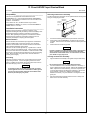
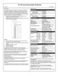
31 Circuit 48VDC Input Genius Block
March 2010
GFK-2041A
Description ___________________________________
Specifications _________________________________
A 48VDC Input Genius Block (IC660BBD040) interfaces the
controller to input signals from 48V devices. The 48V system supply
provides input power. The block logic supply is 24V.
Catalog Numbers
Block
Electronics Assembly
Terminal Assembly
The block accepts inputs from up to 31 input devices. It does not
provide input diagnostics.
This block is suitable for use in Genius Modular Redundancy
systems that utilize the GMR Discrete Input Autotest feature.
Operation and configuration of this feature are described in the GMR
User's Manual (GFK-1277). The block's 31 points accept 48V inputs.
One additional logic point is used as a driver for GMR Autotest.
IC660BBD040
IC660EBD040
IC660TBD040
Block Specifications
Size (height x width x depth)
Weight
LEDs (I/O Block)
LEDs (each circuit)
Isolation
Note: Point 16 is dedicated to the GMR Autotest feature. Point 16
must not be connected to any field device.
8.83” (22.44cm) x 3.58” (9.1cm) x 4.7”
(11.94cm)
4 lbs. (1.8 kg)
Unit OK, I/O Enabled
Individual logic side indicators
Point to point none
Power, I/O to chassis ground ±500VDC (hipot test)
Genius Serial Bus to Ground 250VAC to ground; (1500V hipot test);
note: bus rating also depends on cable type.
Heat Dissipation
11W minimum with 8 inputs
15W maximum with 31 inputs on
Operating voltage
Block 18 to 30 VDC (24V nominal supply)
Field devices 36 to 60 VDC (48V nominal supply)
Supply Ripple (maximum)
10%
DC power supply current, block
150 ma. typical, 300 ma. maximum
Power supply dropout times
4ms at 12 volts, 20ms at 24 volts
GENIUS
48 VDC
Source In/Out
Input Specifications
Input ON voltage relative to (DC-)
Field Device Supply: 36-60V
Input OFF voltage
Field Device Supply: 36-60V
Input impedance (typical)
Input processing time (typical)
Selectable input filter times
Block features include:
Thirty-one configurable input circuits (Points 1-15 and 17-32)
18VDC Block Supply: 22-60 volts
24VDC Block Supply: 30-60 volts
30VDC Block Supply: 39-60 volts
18VDC Block Supply: 0-14 volts
24VDC Block Supply: 0-20 volts
30VDC Block Supply: 0-27 volts
with point 16 ON:
16K Ohms
with point 16 OFF
6K Ohms
1.4ms (plus selectable filter delay)
1, 2, 3, 4, 5, 10, 20, 30, 40, 50, 60, 70, 80,
90, or 100ms
Environmental Specifications
Software configuration of block features
LEDs
Operating temperature
0° C to +60° C (+32° to +140° F)
Storage temperature
-40° to +100° C (-40° to +212° F)
Block LEDs verify proper block operation and CPU communications.
Individual circuit LEDs on the logic side indicate voltage present on
inputs.
Refer to GFK-0867 for product standards and general specifications.
Configurable Features
Selectable Input Filter Time from 1ms to 100ms
Internal test of input states for GMR Autotest
CPU Redundancy type
This datasheet summarizes information about block installation,
configuration, and diagnostics. Your primary reference should be the
Discrete and Analog Blocks User’s Manual. It includes detailed
instructions for block installation and configuration.
Using this Datasheet ___________________________
For additional information about systems and communications, including
bus specifications, refer to the I/O System and Communications Manual.
Block Configuration Notes
Points 1-15 and 17-32 must not be used as output points to
For details about GMR, please refer to the GMR User’s Manual.
drive loads, these points are for 48V input signals only.
Point 16 must be configured as an output and set ON for nonGMR operation. Refer to the "Configuration" section later in this
document.
1
31 Circuit 48VDC Input Genius Block
June 2002
GFK-2041A
Removing an Electronics Assembly
Compatibility _________________________________
The block’s Electronics Assembly can be replaced without removing field
wiring or reconfiguring the block.
This block is compatible with Hand-held Monitor model
IC660HHM501 only. Note that Hand-held Monitor IC660HHM501
version A will only display all references for a 32-circuit block if it is
made the “Active Block”.
Electronics
Assembly
Retaining
Screws
(Qty. 2)
For an Series Six PLC, the Bus Controller may be model
IC660CBB902 or CBB903, any version; or model IC66*CBB900 or
CBB901 version 1.3 or later.
Installation Instructions _________________________
Terminal
Assembly
Carefully inspect all shipping containers for damage. If any
equipment is damaged, notify the delivery service immediately. Save
the damaged shipping container for inspection by the delivery
service. After unpacking the equipment, record all serial numbers.
Save the shipping containers and packing material in case it is
necessary to transport or ship any part of the system.
Connector
Pins
Block Installation
Genius I/O blocks are considered "open equipment" and therefore
must be installed within a protective enclosure. They should be
located in an area that is clean and free of airborne contaminants.
There should be adequate cooling airflow.
1.
Unscrew the retaining screws at the top and bottom of the block.
2.
Using a Block Puller (IC660BLM507), engage the tabs in the first
vent slots. Move the tool to the center of the block and squeeze the
handle.
3.
Pull the Electronics Assembly upward.
Warning
The block can be mounted right side up, or upside down. Leave at
least 2 inches of space between blocks. Mount the block by drilling
two screw or bolt holes for 8-32 hardware. Position the block so that
the notches in the upper and lower flanges line up with the mounting
holes. Mount the block using 8-32 screws. Use star washers to
provide ground integrity.
If power is applied to the field terminals, power is also exposed
on the connector pins at the base of the Terminal Assembly,
and electrical shock hazard exists. Do not touch the connector
pins! Death or injury may result.
Inserting an Electronics Assembly
Grounding
1.
The block’s mounting screws must not be used as the only means
of grounding the block. Connect the green ground screw on the
block to a reliable ground system using a short wire lead, minimum
size AWG #12 (avg 3.3mm2 in cross-section).
Align the Electronics Assembly in the guides and push down firmly.
Caution
Do not exert excessive force; it may damage the block.
Warning
2.
If unusual resistance is met, remove the Electronics Assembly. If
power is applied to the block, DO NOT TOUCH THE CONNECTOR
PINS! Inspect the Terminal Assembly, connector receptacle, and
connector edge board (on the Electronics Assembly). Be sure the
keying matches. Remove any obstacles and reinsert the
Electronics Assembly. Pay close attention to the alignment of the
guide pins.
3.
Secure the Electronics Assembly with the screws on the top and
bottom of the Terminal Assembly.
If mounting screws do not make good ground connection
and the ground screw is not connected to a reliable ground,
the block is not grounded. Electrical shock hazard exists.
Death or personal injury may result.
2
31 Circuit 48VDC Input Genius Block
June 2002
GFK-2041A
Input Signal
Serial Bus Wiring
(48V)
Terminals 1 to 4 are for the serial bus. They accept one AWG #12
wire (avg. 3.3mm2 in cross-section) or two AWG #14 wires (each
avg 2.1mm2). The minimum recommended wire size is AWG #22
(avg .36mm2). Terminals 1 to 4 can also accommodate spade or
ring lugs up to 0.27 inch (6.85 mm) in width with a minimum opening
for a #6 screw, and up to 0.20 inch (5.1 mm) depth from the screw
center to the back barrier. Be sure unshielded wire ends are not
longer than 2 inches (5cm).
Input
Typical Input
Device Wiring
Input 1
5
DC+
7
DC+
9
DC+
14 INPUT 5
15 INPUT 6
16 INPUT 7
17 INPUT 8
18 INPUT 9
19 INPUT 10
20 INPUT 11
21 INPUT 12
24
Volt
Point 16 is
Reserved for
GMR Autotest
ONLY
22 INPUT 13
23 INPUT 14
25 GMR Autotest
Input 17
SERIAL 1
2
SERIAL 2
3
SHIELD IN
4
SHIELD OUT
Serial 1
Serial 2
Shield In
Shield Out
30 INPUT 21
31 INPUT 22
32 INPUT 23
34 INPUT 25
35 INPUT 26
36 INPUT 27
37 INPUT 28
Input 32
38 INPUT 29
39 INPUT 30
40 INPUT31
41 INPUT 32
42 DC43 DC44 DC-
48 Volt
If the block is at either end of the bus, connect a terminating resistor
of the appropriate type (see the System and Communications User’s
Manual for details) across its Serial 1 and Serial 2 terminals.
Terminating
Resistor
INPUT 17
28 INPUT 19
33 INPUT 24
Do not over-torque the terminal screws. Recommended torque for all
terminals on the block is 6in/lb (.678N/M).
Start
of Bus
24 INPUT 15
26
27 INPUT 18
29 INPUT 20
1
DC+
12 INPUT3
13 INPUT 4
Input 15
DC+
10 INPUT 1
11 INPUT 2
Using one of the cable types recommended in the System and
Communications User’s Manual, connect the serial bus to terminals
1- 4.
6
8
45 DC46 DC-
Power Disconnects
It is important to wire power disconnects so that block power and input
power will be removed at the same time. Either switch both supplies at
the same time, or switch the DC-.
End
of Bus
Terminating
Resistor
OK
NO
DC +
Serial 1
Serial 2
Shield In
Shield Out
YES
DC -
Caution
Field Wiring
If I/O circuit power is not removed at the same time as block
power, the block may power up when multiple inputs are
activated, even though one leg of power has been removed
from the block.
Terminals 5 - 46 accept one AWG #14 wire (avg. 2.1mm2 cross
section), two AWG #14 (2.1mm2 cross section) solid wires, or two
AWG #16 (each avg. 1.3mm2 in cross section) stranded wires.
If you want to disable the block without removing power from input
devices, use a Block Puller to unplug the Electronics Assembly. Do not
disconnect H or N to remove power.
Terminals 5-9 are for the positive 24V block supply. Terminals 42-46
are common for both the block supply and the 48V input device
supply.
This block is an inputs-only block. Connect one terminal of a field
device to the positive side of the 48V power supply and the other to
the block (terminals 10-41). All I/O devices must return to the same
power circuit.
LEDs _______________________________________
The block's Unit OK and I/O Enabled LED’s show its operating status:
Unit OK
Depending on layout and current loads, positive and negative
connections can be bussed and made by single wires to the block or
power source.
Point 16 is for GMR Input Autotest applications only. For all
applications, pt. 16 MUST NOT BE connected. However, this
point must be ON in the user's application logic in order to
enable the input points.
ON
ON
I/O
Enabled
ON
OFF
ON
Blinking
Blinking
Blinking
ON
OFF
Alternate Blinking
Synchronous
Blinking
OFF
Don’t
Care
Meaning
Block functioning, CPU communicating
Block functioning
No CPU communications for 3 bus scans
Block functioning, Circuit forced
Circuit fault, CPU communicating
Circuit fault,
No CPU communications for 3 bus scans
Circuit fault, Circuit forced
No CPU communications - block number
conflict
No block power, or block faulty
For each input circuit, the circuit LED indicates the presence of threshold
voltage at the input terminal.
3
31 Circuit 48VDC Input Genius Block
June 2002
GFK-2041A
Block Operation ________________________________
Configuration _________________________________
The block has 31 identical input circuits. All inputs connect to the
positive (+) side of the 48V I/O power supply. The 24V positive
connects to DC+. The negative side of both supplies connects to
DC-.
Block IC660BBD040 has the same Electronics Assembly and firmware
as the 24VDC 32-circuit Genius Source Block, IC660BBD024. Because
it has the same configuration parameters, it will identify itself as a
BBD024 to the Genius Hand Held Monitor and must be configured as a
BBD024 at the 90-70 GBC. Since the IC660BBD040 block is an inputsonly block, it must be configured as described below. First, the block
must be configured with a Hand-held Monitor to:
Configured +48V
as an Input I/O
Terminal
Assembly
DC +
24V
Electronics
Assembly
DC +
Field
Connections
I/O
6.6K
Smart
Switch
Input
Device
Test
Circuit
24V and 48V
common
Return
Control
Logic
10K
From I/O
Point 16
DC -
In a GMR system, this block can provide input diagnostics when set
up for the GMR Input Autotest function, as part of its GMR
configuration. A complete explanation of installation requirements
and GMR Input Autotest diagnostics are included in the GMR User's
Manual (GFK-1277).
Device
Number*
Reference
Address*
Block I/O
Type*
Baud Rate*
If this block is used in a non-GMR system, it provides basic block
diagnostics features.
Inputs and Outputs _____________________________
The block always sends 4 bytes of data each bus scan, and accepts
4 bytes of data each bus scan.
Since the block is configured as a combination block the block will
use 32 input references and 32 output references.
Input Data Format
The block broadcasts 4 bytes of input data each bus scan.
Description
Inputs 1 - 8 (input 1 in bit 0)
1
Inputs 9 - 16 (input 9 in bit 0)
2
Inputs 17 - 24 (input 17 in bit 0)
3
Inputs 25 - 32 (input 25 in bit 0)
Specify its Block I/O Type on the Program Block ID screen. For this
block, the Block I/O Type must be set to "Combination".
Feature
Diagnostics ____________________________________
0
Enter its Reference Number (required only for Series Six and
Series Five PLCs only).
Note: If a block is configured offline, it must be properly grounded and
have a 75 Ohm resistor installed across its Serial 1 and Serial 2
terminals. See the Discrete and Analog Blocks User’s Manual for
instructions. The rest of the features can be configured either using a
Hand-held Monitor, or by sending a Write Configuration datagram to the
block from the host.
DC -
The block's Terminal Assembly includes an active test circuit for
GMR Autotest applications.
Byte #
Enter its Device Number (serial bus address).
Output Data
The block receives 4 bytes of output data from the bus controller
each bus scan. However, because this block is only compatible with
input devices, the output data is not used by the block, except to set
point 16 ON.
The Hand-held Monitor displays the current states of 16 circuits at a
time on line 4 of the Monitor Block screen. Press a function key to
see the next 16 circuits.
Factory
Setting
null
Block
none
Block
input
Block
Selections
0 to 31 (a number
must be selected)
Depends on host
CPU type
input, output,
combination
153.6 std, 153.6
ext, 76.8, 38.4 Kbd
enabled, disabled
Non-GMR
Application
Settings
0 to 31 (a number
must be selected)
Depends on host
CPU type
combination
Pulse Test for
Outputs
Input Filter
Time
Block
153.6
std
enabled
Block
20ms
Block I/O
Type
Circuit I/O
Type
Report Faults
Hold Last
State
Output
Default State
BSM Present
BSM
Controller **
Output
Default Time
Block
input
Circuit
input
1, 2, 3, 4, 5, 10 to
100ms in 10ms
steps
input, output,
combination
input, output
Circuit
Circuit
yes
no
yes, no
yes, no
Circuit
off
on, off
Block
Block
no
no
yes, no
yes, no
Block
3 bus
scans
Block
none
Block
off
(for bus
redundancy) 2.5 or
10 seconds
none, hot standby,
duplex, GMR
on, off
none, hot standby,
duplex, GMR
off
Block
disabled
enabled, disabled
enabled, disabled
CPU
Redundancy
Duplex
Default
Configuration
Protection
Hand-held Monitor I/O Display
Circuit
or
Block
Block
153.6 std, 153.6 ext,
76.8, 38.4 Kbd
disabled
1, 2, 3, 4, 5, 10 to
100ms in 10ms
steps
combination
input (1-15, 17-32)
output (16)
no
no
point 16: ON
all other points: N/A
yes, no
no
N/A
* Configured using HHM, from Program Block ID screen.
** This block cannot act as a BSM Controller.
REF
17-32IO
1234567890123456
IIIIIIIIIIIIIIII
1011010101101101
4
31 Circuit 48VDC Input Genius Block
June 2002
GFK-2041A
Regardless of whether fault reporting is enabled, the block detects any
faults on the circuit and takes appropriate actions if faults occur. The
Unit OK LED blinks when a fault occurs, and a fault report is sent to a
Hand-held Monitor. The fault condition must be corrected for proper
operation of the block.
Description of Configurable Features
Pulse Test: If the block will be used in a GMR system and use the
GMR Input Autotest feature, Pulse Testing should be enabled (the
dafault).
If the CPU requests diagnostic information from the block using Read
Diagnostics datagrams, the block returns current diagnostics for all
circuits, including any with CPU fault reporting disabled.
If the block will NOT be used in a GMR system, Pulse Testing
should be changed to disabled.
Hold Last State: Not used for inputs.
Input Filter Time: A filter time can be selected for inputs on the
block. (The same filter will apply to all inputs). The default filter time
is 20ms.
Output Default State: Not used for inputs. For all applications, the Output
Default State for point 16 should be ON.
The block continuously samples an input for the length of the filter
time period. If the input remains either on or off for the length of the
Filter Time, the block recognizes its state. For example:
OFF
ON
BSM Present: If the block is connected to a single bus or to just one
trunk of a dual bus, BSM Present should be set to NO.
Select YES if the block is located in a cluster connected to dual busses
via a Bus Switching Module.
STATE
20mS
SIGNAL
Sampled Inputs
ON for 5mS
not recognized
If FILTER TIME =20mS
Sampled Inputs
ON for 30mS
recognized by block
BSM Controller: A BSM Controller is a block to which a Bus Switching
Module is directly attached, which controls the BSM’s switching action.
Selecting a block to be a BSM Controller block has no effect on the
block’s I/O type - the block can still be configured as an inputs-only
block, but circuit #1 cannot be physically used as an input. The first
circuit will not be under CPU control.
Sampled Inputs
OFF for 3mS
not recognized
To change this configuration with a Hand-held Monitor, the block must
first be configured for BSM PRESENT. The BSM CONTROLLER menu
will not appear if BSM PRESENT is set to NO.
An input filter helps reject spurious noise spikes and multiple inputs
generated by the bounce of mechanical devices. In controlled,
noise-free environments, signals generated by clean, solid state
electronics may be unnecessarily slowed by a filter, delaying system
response. In such an environment, no additional filter time is
needed.
Output Default Time: Not used for inputs.
CPU Redundancy:
This feature determines how a block will utilize
output data received from single or redundant CPUs.
If the block will be used in GMR system, refer to the configuration
instructions in the GMR User's Manual to choose the appropriate CPU
Redundancy option. Not all input blocks in a GMR system are configured
for GMR Redundancy. Do not try to configure a block for GMR mode
without referring to the detailed configuration instructions in the GMR
User's Manual.
In noisy environments, select a longer filter time to prevent noise
from possibly causing erratic or unsafe system operations. The filter
time can be 1, 2, 3, 4, 5, 10, 20, 30, 40, 50, 60, 70, 80, 90, or
100ms.
I/O Circuit Type: An earlier configuration step selected the Block
I/O type (on the Program Block ID screen). This step selects the
I/O circuit types. The default Block I/O Type and I/O Circuit Type are
Input.
Duplex Default State: Not used for inputs.
Configuration Protection: This feature can be used to protect the block’s
configuration, preventing changes from the CPU or Hand-held Monitor.
It can only be selected from the Hand-held Monitor. To make
subsequent changes, protection must be removed again using the
Hand-held Monitor. For a new block, configuration is unprotected.
Before a block is used in the system, its configuration should be
protected.
If the block is used in a GMR system and will use the GMR Autotest
feature, the Block I/O Type must be set to Combination, and Point
16 must be configured as an output. See the GMR User's Manual for
configuration instructions.
If the block is used in a non-GMR system, its Block I/O Type must
be configured as "Combination". All circuits except 16 must be
configured as inputs (the default). Point 16 must be an output, but
cannot be used for a physical input device, as explained previously.
Point 16 must be set ON in the user's application logic to enable
input operation on the other points. It is recommended that the
default state for point 16 be set to ON. This will reduce power and
permit continued display of input states on point LEDs when I/O
Enable is OFF.
Report Faults to CPU: Fault reports to the host can be disabled or
enabled for any circuit on a block.
If Fault Reporting is enabled for a circuit, the block will send a
message to the host if any fault occurs on that circuit.
If Fault reporting is disabled, the block will not send fault reports for
that circuit.
5