1
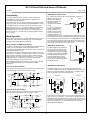
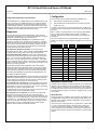
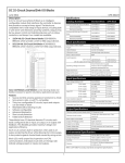
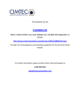
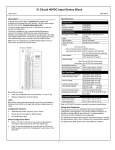
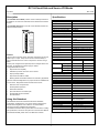
DC 16-Circuit Sink and Source I/O Blocks
April 2005
GFK-1778C
Description
Specifications
The 24/48 VDC Source Block provides current to field output devices. It
is suitable for use with 3-wire solid state sensors and electromechanical
sensors.
Catalog Numbers
Block type
24/48 VDC 16 Circuit Source I/O Block
Terminal Assembly only
Electronics Assembly only
24/48 VDC 16 Circuit Sink I/O Block
Terminal Assembly only
Electronics Assembly only
Block Specifications
Size (height x width x depth)
The 24/48 VDC Sink Block, for use with 3-wire solid-state sensors and
electromechanical sensors.
24/48 VDC
Source In/Out
Weight
LEDs (I/O Block)
LEDs (each circuit)
Block to block Isolation
Heat Dissipation
Operating voltage
Ripple (maximum)
Required DC power
Power supply dropout time
Input Specifications
For standard input, voltage relative to
DCInput ON
24 VDC supply
48 VDC supply
Input OFF
24 VDC supply
48 VDC supply
Input impedance (typical)
Input processing time (typical)
Selectable input filter times
Input diagnostics
Output Specifications
Output current (steady state)
Maximum inrush current
Block output current
Output OFF leakage current
Maximum switching frequency
Output turn-on delay (maximum)
Output voltage drop
Minimum Recommended Load
Output Diagnostics
Features
This block has 16 discrete circuits, each easily configured to be an input,
tristate input, or output. Output circuits can be connected directly to
input circuits without the use of other components or inversion of logic
states.
Control power is tapped off the input/output device voltages wired to the
terminals. No separate block power supply is needed.
Configurable features include:
Output Pulse Test capability
Selectable Input Filter Time from 10ms to 100ms
Output powerup defaults
Output Hold Last State or default
Blocking diodes and feedback resistors for redundancy applications
The block’s advanced diagnostics can pinpoint causes of installation and
run-time errors. Diagnostics features of these blocks include:
Electronic short circuit protection
Overtemperature protection
Failed switch detection
Open wire detection for tristate inputs
Overload detection and shutdown
No-load detection
Using this Datasheet
Environmental Specifications
Operating Temperature
Storage Temperature
Humidity
Vibration
This datasheet summarizes information about block installation,
configuration, and diagnostics. Your primary reference should be the
Discrete and Analog Blocks User’s Manual. It includes detailed
instructions for block installation and configuration.
For additional information about systems and communications, including
bus specifications, refer to the I/O System and Communications Manual.
For details about GMR, please refer to the GMR User’s Manual.
16 circuit discrete input and output
IC66*BRD020
IC66*TRD020
IC66*ERD020
IC66*BRD021
IC66*TRD021
IC66*ERD021
8.83” (22.44cm) x 3.56” (9.05cm) x 4.42”
(11.23cm)
4 lbs. (1.8 kg)
Unit OK, I/O Enabled
Individual load side indicators
1500V
91.5 Watts with 16 outputs on at 2 Amps.
18-56 VDC (24/48 V), 18-30 VDC (24 V)
10%
150mA typical, 300mA maximum
10ms
Source
Sink
16-24 VDC
0-8 VDC
32-48 VDC
0-16 VDC
0-7 VDC
17-24 VDC
0-14 VDC
34-48 VDC
5.6K Ohms (24/48V), 1.8K Ohms (24V)
1.7ms (plus selectable filter delay)
5-100ms
Open Wire, Overtemperature, Failed Switch
2 Amps per circuit
10 Amps up to 10ms
15 Amps at 35°C
1.0 mA
Once per second (high inrush current)
1ms
2.0 volts maximum at 2 Amps inrush
50 mA with No Load enabled
Short Circuit, Overload, No Load, Failed
Switch, Overtemperature
-0° to +60°C (32° to +140°F)
-40 °C (-40° to +212°F)
5% to 95% (non-condensing)
5-10 Hz 0.2” (5.08mm) displacement, 10200 Hz at 1G
Refer to GFK-0867 for product standards and general specifications.
1
DC 16-Circuit Sink and Source I/O Blocks
April 2005
GFK-1778C
GMR 2-Block T Output Group
Compatibility
A T- output group consists of two source-type blocks, connected in
parallel on one side of the
Bus B
Bus A
load. The other side of the
load is tied to ground. The
two blocks must be
connected to two different
Source Blocks
A
busses.
Any Hand-held Monitor can be used with this block. HHM version
IC66*HHM501 is required to change baud rate configuration or to
configure the block for redundancy.
For an IC697 series PLC, the CPU and programming software must be
version 2.0 or later. The bus controller must be IC697BEM731C or later.
For an IC600 series PLC, the CPU must be rev. 105 or later. For an
IC600 series Plus PLC, rev. 110 or later is required. The programming
software must be rel. 4.02 or later. If the bus controller is model
IC66*CBB900, it must be version C or later. For an IC550 series PLC,
the CPU must be rev. 3.0 or later. The programming software must be
rel. 2.01 or later.
B
In a 2-block T output group,
Load
current to output loads is
shared. Therefore, it is not
possible to be sure exactly
0 Volts
how much power is being
provided by each block. If
16-circuit blocks in a 2-block T output group are configured for No Load
fault reporting, the minimum connected load that can be used is 100mA.
Block Operation
Each circuit can be configured as an input, a tristate input, or an output.
If the block is configured as a combination block, output feedback is
provided via the corresponding input references.
In a T-output group, the blocking diodes in block IC66*BRD020 minimize
the reverse current into a block that is powered down or not driving the
load. The blocking diodes prevent the block from being powered through
its I/O points by the other block in the output group.
Wiring Changes for GMR Output Groups
GMR I-Block Output Group
An isolation or blocking diode is incorporated into the Terminal Assembly
for every point on these blocks. These internal diodes make it
unnecessary to add external diodes in series with outputs, to perform the
same blocking/isolation function.
An I-Block Output Group consists of a
source-type block connected to one
side of the load and a sink-type block
connected to the other side. This type
of group is most suitable for redundant
shutdown applications. Both blocks in
an I-Block Output Group must be
either 16-circuit or 32-circuit blocks.
The two blocks must be connected to
two different busses.
For example, these blocks do not require external diodes in series with
“Q16” outputs in “Power feed” applications shown in GFK-1277. External
diodes are also not needed in conjunction with the standard external
4700pF capacitor, when these blocks are used in “H”, “T” or “I”-pattern
GMR Output Groups. The blocking or isolation function is already
provided by the diodes in the Terminal Assembly.
External isolation diodes are still needed on common inputs. See GFK1277 for additional information about using diodes with GMR
applications.
Bus A
Bus B
Source Block
A
Load
Sink Block
B
GMR H-Block Output Group
16 Circuit DC Sink I/O Blocks
In an H-Block Output Group, two source-type Genius blocks are
connected in parallel on one side of each load and two sink-type Genius
blocks are connected in parallel on the other side. An H-Block Output
Group requires either two or three Genius busses.
A DC sink block has all output devices connected to the positive (+) side
of the power supply. Inputs control the negative (-) side.
DC+
Configured
as an
Output
Configured
as an
Input
Output
Device
DC+
5.6K Ohms
LED
Smart
Switch
I/O
1 - 16
Bus A Bus C
Processor
Bus B
Source Blocks
Bus B
Bus A
Source Blocks
100K Ohms
Input
Device
Field
Connections
Two Busses
Three Busses
DC-
Terminal
Assembly
Electronics
Assembly
A
DC-
B
A
Load
B
Load
16 Circuit DC Source I/O Block
C
A DC source block has all output devices connected to the negative (-)
side of the power supply. Inputs control the positive (+) side.
DC+
Configured
as an
Input
Input
Device
I/O
1 - 16
Configured
as an
Output
Sink Blocks
Smart
Switch
Processor
5.6K Ohms
Output
Device
Field
Connections
LED
DC-
Terminal
Assembly
Electronics
Assembly
C
D
Sink Blocks
If the blocks are on three busses, one source and one sink block in the
group must be on the same bus. The two blocks on the same bus must
have different serial bus addresses. If the blocks are on two busses, one
source and one sink block are on one bus and the other source and sink
block are on the other bus. Any blocks that share a bus must have
different serial bus addresses.
DC+
100K Ohms
D
DC-
2
DC 16-Circuit Sink and Source I/O Blocks
April 2005
GFK-1778C
Configuration
Configuration Required for Input Autotest
First, the block must be configured with a Hand-held Monitor to:
For 24/48VDC blocks in a GMR system, if Input Autotesting for the Input
Group is turned ON in the GMR Configuration, then during the Genius
configuration of the blocks in the group, the Output Pulse Test feature
must be disabled. Otherwise, circuits that would normally pass the Input
Autotest are incorrectly reported as having failed. When Output Autotest
is disabled, the Input Autotest feature functions correctly.
Enter its Device Number (serial bus address).
Enter its Reference Number (required only for IC600 and IC550
series PLCs only).
In addition, unless all circuits on the block will be inputs, the Block I/O
Type must be set to either Outputs or Combination on the Program Block
ID screen.
Diagnostics
Note: If a block is configured offline, it must be properly grounded and
have a 75 Ohm resistor installed across its Serial 1 and Serial 2
terminals. See the Discrete and Analog I/O Blocks User’s Manual for
instructions.
The block always performs its standard diagnostic checks, plus two
configurable output diagnostics. The block reports all faults to the Handheld Monitor, and takes appropriate corrective action.
The rest of the features can be configured either using a Hand-held
Monitor, or by sending a Write Configuration datagram to the block from
the host.
Short Circuit Diagnostic (standard) If the instantaneous current
exceeds 10 Amps at turn-on, the block turns the output off. The block
attempts to restart the load; if two attempts are unsuccessful, the output
circuit is forced off and the block sends a SHORT CIRCUIT message.
The cause of the current surge must be removed, then the diagnostic
must be cleared from the HHM or the CPU.
Feature
Circuit
or Block
Factory
Setting
Selections
Baud Rate
B
153.6 std
153.6 std, 153.6 ext, 76.8, 38.4
Block I/O Type
B
input
input, output, combination
Pulse Test
B
enabled
enabled, disabled
Failed Switch Diagnostic (standard) For an output, Failed Switch is
reported if the circuit’s switch state is not the same as its commanded
state. The block sends a FAILED SWITCH message identifying the
failed circuit. The logic state of the circuit is set to OFF. If the output
switch has failed shorted (or closed), current flow is not interrupted when
the block forces the output state OFF. Action external to the block must
be taken to remedy the problem.
Input Filter Time
B
20ms
5-100ms
Several additional switch faults independent of the output state are
detected and reported as Failed Switch faults on both input and outputconfigured circuits. Examples include loss of communications with the
block’s internal microprocessor and some internal power supply faults.
Detect No Load
Overload Shutdown
BSM Present
B
no
yes, no
Output Timeout
B
3 bus scans
2.5, 10 seconds
none, standby, duplex, GMR
Overtemperature Diagnostic (standard) If the block’s internal
temperature exceeds 120º C, the block sends an OVERTEMPERATURE
message and turns off the circuit to protect its internal electronics.
Note that in GMR applications, Failed Switch operates differently. See
the GMR User’s Manual for details.
Open Wire Diagnostic (standard) Indicates electrical (not mechanical)
malfunctions on a tristate input. The circuit must have a non-inductive
resistor placed as close as practical to the actual dry contacts (such as
across the field device terminals), as shown previously.
Circuit I/O Type
C
input
input, output, tristate input
Report Faults
C
yes
yes, no
Hold Last State
C
no
yes, no
Output Default State
C
off
on, off
C
yes
yes, no
C
yes
yes, no
Redundancy Mode
B
none
Duplex Default
B
off
on, off
Config. Protect
B
disabled
enabled, disabled
Installation Instructions
Overload Diagnostic (configurable) If Overload Shutdown is enabled,
the block will turn the output off and send an OVERLOAD message if a
load exceeds 2.8 Amps DC continuously for 10ms. currents. Exceeding
these limits may cause an overtemperature fault.
Carefully inspect all shipping containers for damage. If any equipment is
damaged, notify the delivery service immediately. Save the damaged
shipping container for inspection by the delivery service. After unpacking
the equipment, record all serial numbers. Save the shipping containers
and packing material in case it is necessary to transport or ship any part
of the system.
A load that requires more than 2 Amps DC can be configured not to shut
off at this level or send the OVERLOAD message.
No Load Diagnostic (configurable) If a load does not continuously
draw 50mA from the output circuit, the block sends a NO LOAD
message. A No Load condition may cause an HHM monitoring the block
to display 0 for the circuit although there is voltage at the output and the
circuit LED is on. This diagnostic should be not be used for circuits on
which very small loads (small relays, transformers, or indicating lamps)
will draw less than 50 mA. In GMR applications, No Load operates
differently. See the GMR User’s Manual for details.
Block Mounting
Genius I/O blocks are considered "open equipment" and therefore must
be installed within a protective enclosure. They should be located in an
area that is clean and free of airborne contaminants. There should be
adequate cooling airflow.
The block can be mounted right side up, or upside down. Leave at least
2 inches of space between blocks. Mount the block by drilling two
screw or bolt holes for 8-32 hardware. Position the block so that the
notches in the upper and lower flanges line up with the mounting holes.
Mount the block using 8-32 screws. Use star washers to provide ground
integrity.
3
DC 16-Circuit Sink and Source I/O Blocks
April 2005
GFK-1778C
Grounding
Installation in Hazardous Locations
The block’s mounting screws must not be used as the only means of
grounding the block. Connect the green ground screw on the block to a
reliable ground system using a short wire lead, minimum size AWG #12
(avg 3.3mm2 in cross-section).
These Products have UL (C-US) Hazardous Location, CE, and FM
Class 1 Division 2 Group A, B, C & D approvals.
•
Warning
•
If mounting screws do not make good ground connection and
the ground screw is not connected to a reliable ground, the
block is not grounded. Electrical shock hazard exists. Death or
personal injury may result.
•
Removing an Electronics Assembly
The block’s Electronics Assembly can be replaced with a compatible
model without removing field wiring or reconfiguring the block.
THIS EQUIPMENT IS SUITABLE FOR USE IN CLASS I,
DIVISION 2, GROUPS A, B, C, D OR NON-HAZARDOUS
LOCATIONS ONLY.
WARNING - EXPLOSION HAZARD - SUBSTITUTION OF
COMPONENTS MAY IMPAIR SUITABILITY FOR CLASS I,
DIVISION 2;
WARNING - EXPLOSION HAZARD - WHEN IN
HAZARDOUS LOCATIONS, TURN OFF POWER BEFORE
REPLACING OR WIRING MODULES; AND
WARNING - EXPLOSION HAZARD - DO NOT DISCONNECT
EQUIPMENT UNLESS POWER HAS BEEN SWITCHED
OFF OR THE AREA IS KNOWN TO BE NONHAZARDOUS.
Electronics
Assembly
Block Wiring
Retaining
Screws
(Qty. 2)
All terminals accept one AWG #12 wire (avg 3.3mm2 cross-section) or
two AWG #14 wires (each avg 2.1mm2 in cross-section). The minimum
recommended wire size is AWG #22 (avg .36mm2 in cross-section).
Block terminals can also accommodate spade or ring terminals up to
0.27 inch (6.85mm) wide with a minimum opening for a #6 screw, and up
to 0.20 inch (5.1mm) depth from the screw center to the back barrier. Be
sure unshielded wire ends are not longer than 2 inches (5 cm).
Terminal
Assembly
Do not overtorque the terminal screws. Recommended torque for all
terminals is 6 in/lb (.678 N/M).
Connector
Pins
Serial Bus Wiring
1.
Unscrew the retaining screws at the top and bottom of the block.
2.
Using a Block Puller (IC660BLM507), engage the tabs in the first
vent slots. Move the tool to the center of the block and squeeze the
handle.
Pull the Electronics Assembly upward.
3.
Using one of the cable types recommended in the System and
Communications User’s Manual, connect the serial bus to terminals 1- 4.
(If a Bus Switching Module will be connected directly to the block, see
below instead).
Warning
If power is applied to the field terminals, power is also exposed
on the connector pins at the base of the Terminal Assembly, and
electrical shock hazard exists. Do not touch the connector pins!
Death or injury may result.
Inserting an Electronics Assembly
1.
SERIAL 1
2
SERIAL 2
3
SHIELD IN
4
SHIELD OUT
If the block is at either end of the bus, connect a terminating resistor of
the appropriate type (see the System and Communications User’s
Manual for details) across its Serial 1 and Serial 2 terminals.
Align the Electronics Assembly in the guides and push down firmly.
Caution
2.
1
Start
of Bus
Do not exert excessive force; it may damage the block.
If unusual resistance is met, remove the Electronics Assembly. If
power is applied to the block, DO NOT TOUCH THE CONNECTOR
PINS! Inspect the Terminal Assembly, connector receptacle, and
connector edge board (on the Electronics Assembly). Be sure the
keying matches. Remove any obstacles and reinsert the
Electronics Assembly. Pay close attention to the alignment of the
guide pins.
Terminating
Resistor
Serial 1
Serial 2
Shield In
Shield Out
End
of Bus
Terminating
Resistor
Serial 1
Serial 2
Shield In
Shield Out
Wiring for a Bus Switching Module
Secure the Electronics Assembly with the screws on the top and
bottom of the Terminal Assembly.
If the block will be a BSM Controller, attach the Bus Switching Module to
the block’s serial bus terminals. Attach the serial bus cables to the BSM
as described in the Bus Switching Module datasheet. Wire the BSM like
a load to circuit 1. Connect either BSM pigtail wire to terminal 6.
Connect the other BSM wire to DC-.
4
DC 16-Circuit Sink and Source I/O Blocks
April 2005
GFK-1778C
Power Connections
Wiring for Tristate Inputs
Connect a DC power source to the DC+ terminal (5) and the return to the
DC- terminal (22). Depending on the layout and current loads, positive
and negative connections can be bussed and made by individual wires
back to the block or power source.
If any input is configured as a Tristate Input, install a resistor across the
dry contacts of the input device. This added resistance is required to use
the Open Wire diagnostic. The LED will glow dimly as a result.
+
Power Disconnects
It is important to wire block power disconnects so that block power and
input power will be removed at the same time. Locate the power
disconnect as shown below.
YES
NO
IN
-
DC SOURCE
BLOCK
DC+
The resistor should be 5.1K Ohms, 1/2 Watt or larger.
LOAD
Connections for a DC Sink Block
DC-
Any circuit can be an input or output. Connect one terminal of the device
to the block (terminals 6-21). Connect outputs to DC+ and inputs to DC.
Caution
If circuit power is not removed at the same time as block power, the
block may power up when multiple inputs are activated, even
though one leg of power has been removed from the block.
Connections for a DC Source Block
Any circuit can be an input or output. Connect one terminal of the device
to the block (terminals 6-21). Connect outputs to DC- and inputs to
DC+. No logic inversion is needed.
5
FIELD
INPUT
DEVICES
DC+
DC-
6
1
7
2
8
3
9
4
10
5
11
6
6
1
12
7
7
2
13
8
8
3
14
9
9
4
10
5
11
6
12
7
13
8
19 14
14
9
20 15
FIELD
OUTPUT
DEVICES
FIELD
INPUT
DEVICES
15 10
LOAD
16 11
DC+
DC-
15 10
LOAD
17 12
22
17 12
LOAD
18 13
LOAD
21 16
16 11
DC+
DC+
5
LOAD
DC-
LOAD
FIELD
OUTPUT
DEVICES
18 13
19 14
DC Sink Block, Wiring for Tristate Inputs
LOAD
If any input is configured as a Tristate Input, install a resistor across the
dry contacts of the input device. This added resistance is required to use
the Open Wire diagnostic. The LED will glow dimly as a result.
20 15
21 16
22
LOAD
DC-
+
IN
-
For a 24/48 VDC block, the resistor should be 5.1K Ohms, 1/2 Watt or
larger. For a 24 VDC block, it should be 1.6K Ohms.
5
DC 16-Circuit Sink and Source I/O Blocks
April 2005
GFK-1778C
LEDs
The block's Unit OK and I/O Enabled LEDs show its operating status:
Unit OK
I/O Enabled
Meaning
ON
ON
Block functioning, CPU communicating
ON
OFF
Block functioning, No CPU communications for 3 bus
scans
ON
Blinking
Block functioning, Circuit forced
Blinking
ON
Circuit fault, CPU communicating
Blinking
OFF
Circuit fault, No CPU communications for 3 bus scans
Alternate Blinking
Circuit fault, Circuit forced
Synchronous Blinking
No CPU communications - block number conflict
OFF
No block power, or block faulty
OFF
Each circuit has its own LED. If the circuit is configured as an input, the
LED indicates the presence of threshold voltage at the input terminal. If
the circuit is configured as an output, the LED indicates the actual state
of the load.
6