1
Programming Manual
WINMAG plus
Item No. 013610
PC Control Software for
Windows 2003 / Windows XP pro
Windows Vista
P03126-05-0G0-03
2008-03-31
Software-Version
V02.xx
Subject to change
without notice
2
Programming manual WINMAG plus
Table of Contents
Introduction . . . . . . . . . . . . . . . . . . . . . . . . . . . . . . . . . . . . . . . . . . . . . . . . . . . . . . . . . . . . . . . . . . . . . . . . . . . . . . 5
1.
General . . . . . . . . . . . . . . . . . . . . . . . . . . . . . . . . . . . . . . . . . . . . . . . . . . . . . . . . . . . . . . . . . . . . . . . . . . . 6
1.1 What is WINMAG plus . . . . . . . . . . . . . . . . . . . . . . . . . . . . . . . . . . . . . . . . . . . . . . . . . . . . . . . . . . . 6
1.2 Why WINMAG plus? . . . . . . . . . . . . . . . . . . . . . . . . . . . . . . . . . . . . . . . . . . . . . . . . . . . . . . . . . . . . . 8
1.3 WINMAG plus versions . . . . . . . . . . . . . . . . . . . . . . . . . . . . . . . . . . . . . . . . . . . . . . . . . . . . . . . . . . . 9
1.3.1 Demo version . . . . . . . . . . . . . . . . . . . . . . . . . . . . . . . . . . . . . . . . . . . . . . . . . . . . . . . . . . . . . 9
1.3.2 Single-station version . . . . . . . . . . . . . . . . . . . . . . . . . . . . . . . . . . . . . . . . . . . . . . . . . . . . . . . 9
1.3.3 Process Visualization . . . . . . . . . . . . . . . . . . . . . . . . . . . . . . . . . . . . . . . . . . . . . . . . . . . . . . . 9
1.3.4 Multi-station version . . . . . . . . . . . . . . . . . . . . . . . . . . . . . . . . . . . . . . . . . . . . . . . . . . . . . . . . 9
1.3.4.1
Multi-station . . . . . . . . . . . . . . . . . . . . . . . . . . . . . . . . . . . . . . . . . . . . . . . . . . . . . 10
1.3.4.2
Distributed network . . . . . . . . . . . . . . . . . . . . . . . . . . . . . . . . . . . . . . . . . . . . . . . 11
1.3.4.3
Several Single-stations versions in a network . . . . . . . . . . . . . . . . . . . . . . . . . . . 11
1.4 Licensing/Dongle . . . . . . . . . . . . . . . . . . . . . . . . . . . . . . . . . . . . . . . . . . . . . . . . . . . . . . . . . . . . . . 12
1.4.1 Licensing information . . . . . . . . . . . . . . . . . . . . . . . . . . . . . . . . . . . . . . . . . . . . . . . . . . . . . . 13
2
System requirements . . . . . . . . . . . . . . . . . . . . . . . . . . . . . . . . . . . . . . . . . . . . . . . . . . . . . . . . . . . . . . . .
2.1 Operating system . . . . . . . . . . . . . . . . . . . . . . . . . . . . . . . . . . . . . . . . . . . . . . . . . . . . . . . . . . . . . .
2.2 SOFTWARE requirements . . . . . . . . . . . . . . . . . . . . . . . . . . . . . . . . . . . . . . . . . . . . . . . . . . . . . . .
2.3 PC requirements . . . . . . . . . . . . . . . . . . . . . . . . . . . . . . . . . . . . . . . . . . . . . . . . . . . . . . . . . . . . . . .
14
14
14
14
3
Connections to WINMAG plus . . . . . . . . . . . . . . . . . . . . . . . . . . . . . . . . . . . . . . . . . . . . . . . . . . . . . . . .
3.1
............................................................................
3.2 Connection to the IGIS network . . . . . . . . . . . . . . . . . . . . . . . . . . . . . . . . . . . . . . . . . . . . . . . . . . .
3.2.1 IGIS-Loop connection . . . . . . . . . . . . . . . . . . . . . . . . . . . . . . . . . . . . . . . . . . . . . . . . . . . . . .
3.2.1.1 User address allocation within the security network IGIS-LOOP . . . . . . . . . . . . . .
3.2.1.1.1 Ring address . . . . . . . . . . . . . . . . . . . . . . . . . . . . . . . . . . . . . . . . . . . .
3.2.1.1.2 Ring sub-address . . . . . . . . . . . . . . . . . . . . . . . . . . . . . . . . . . . . . . . . .
3.2.1.1.3 Device address . . . . . . . . . . . . . . . . . . . . . . . . . . . . . . . . . . . . . . . . . .
3.2.1.1.4 Configuration example . . . . . . . . . . . . . . . . . . . . . . . . . . . . . . . . . . . . .
3.3 Dial-up connection . . . . . . . . . . . . . . . . . . . . . . . . . . . . . . . . . . . . . . . . . . . . . . . . . . . . . . . . . . . . .
3.4 Event protocol connection . . . . . . . . . . . . . . . . . . . . . . . . . . . . . . . . . . . . . . . . . . . . . . . . . . . . . . . .
3.5 General connection via the ConnectionServer . . . . . . . . . . . . . . . . . . . . . . . . . . . . . . . . . . . . . . . .
3.6 Interface via OPC server . . . . . . . . . . . . . . . . . . . . . . . . . . . . . . . . . . . . . . . . . . . . . . . . . . . . . . . .
3.6.1 General . . . . . . . . . . . . . . . . . . . . . . . . . . . . . . . . . . . . . . . . . . . . . . . . . . . . . . . . . . . . . . . . .
3.6.2 Use of the OPC server . . . . . . . . . . . . . . . . . . . . . . . . . . . . . . . . . . . . . . . . . . . . . . . . . . . . .
3.6.3 OPC interfaces . . . . . . . . . . . . . . . . . . . . . . . . . . . . . . . . . . . . . . . . . . . . . . . . . . . . . . . . . . .
3.6.4 Display of WINMAG plus data types on OPC data types . . . . . . . . . . . . . . . . . . . . . . . . . . .
3.6.5 Address space structure . . . . . . . . . . . . . . . . . . . . . . . . . . . . . . . . . . . . . . . . . . . . . . . . . . . .
3.7 OPC client interface . . . . . . . . . . . . . . . . . . . . . . . . . . . . . . . . . . . . . . . . . . . . . . . . . . . . . . . . . . . .
3.7.1 General . . . . . . . . . . . . . . . . . . . . . . . . . . . . . . . . . . . . . . . . . . . . . . . . . . . . . . . . . . . . . . . . .
3.7.2 Program start . . . . . . . . . . . . . . . . . . . . . . . . . . . . . . . . . . . . . . . . . . . . . . . . . . . . . . . . . . . .
3.7.3 Configuration and operation . . . . . . . . . . . . . . . . . . . . . . . . . . . . . . . . . . . . . . . . . . . . . . . . .
3.7.3.1
General . . . . . . . . . . . . . . . . . . . . . . . . . . . . . . . . . . . . . . . . . . . . . . . . . . . . . . . .
3.7.3.2
Add server . . . . . . . . . . . . . . . . . . . . . . . . . . . . . . . . . . . . . . . . . . . . . . . . . . . . . .
3.7.3.3
Add tags . . . . . . . . . . . . . . . . . . . . . . . . . . . . . . . . . . . . . . . . . . . . . . . . . . . . . . . .
3.7.3.4
Store configuration file . . . . . . . . . . . . . . . . . . . . . . . . . . . . . . . . . . . . . . . . . . . . .
3.7.3.5
New configuration . . . . . . . . . . . . . . . . . . . . . . . . . . . . . . . . . . . . . . . . . . . . . . . .
3.7.3.6
Start communication . . . . . . . . . . . . . . . . . . . . . . . . . . . . . . . . . . . . . . . . . . . . . .
3.7.3.7
Global parameters . . . . . . . . . . . . . . . . . . . . . . . . . . . . . . . . . . . . . . . . . . . . . . . .
3.7.3.8
File format of configuration file . . . . . . . . . . . . . . . . . . . . . . . . . . . . . . . . . . . . . . .
3.7.3.9
Known problems and restrictions . . . . . . . . . . . . . . . . . . . . . . . . . . . . . . . . . . . . .
15
15
16
16
17
17
17
17
17
20
20
20
21
21
21
21
22
22
23
23
23
24
24
24
25
26
26
27
27
28
28
4.
Programming WINMAG plus . . . . . . . . . . . . . . . . . . . . . . . . . . . . . . . . . . . . . . . . . . . . . . . . . . . . . . . . . .
4.1. General . . . . . . . . . . . . . . . . . . . . . . . . . . . . . . . . . . . . . . . . . . . . . . . . . . . . . . . . . . . . . . . . . . . . . .
4.1.1 Programming procedure . . . . . . . . . . . . . . . . . . . . . . . . . . . . . . . . . . . . . . . . . . . . . . . . . . . .
4.1.2 Terms . . . . . . . . . . . . . . . . . . . . . . . . . . . . . . . . . . . . . . . . . . . . . . . . . . . . . . . . . . . . . . . . . .
4.1.3 Message structure . . . . . . . . . . . . . . . . . . . . . . . . . . . . . . . . . . . . . . . . . . . . . . . . . . . . . . . .
4.1.4 User-defined programming . . . . . . . . . . . . . . . . . . . . . . . . . . . . . . . . . . . . . . . . . . . . . . . . . .
29
29
29
31
33
33
Programming manual WINMAG plus
4.2
3
Internal programming functions . . . . . . . . . . . . . . . . . . . . . . . . . . . . . . . . . . . . . . . . . . . . . . . . . . . . 34
4.2.1 Selecting internal edit functions . . . . . . . . . . . . . . . . . . . . . . . . . . . . . . . . . . . . . . . . . . . . . . 34
4.2.1.1
System configuration list . . . . . . . . . . . . . . . . . . . . . . . . . . . . . . . . . . . . . . . . . . . . 34
4.2.1.3
“Edit graphics” tool bar . . . . . . . . . . . . . . . . . . . . . . . . . . . . . . . . . . . . . . . . . . . . . 37
4.2.2 System configuration options . . . . . . . . . . . . . . . . . . . . . . . . . . . . . . . . . . . . . . . . . . . . . . . . 38
4.2.2.1
Edit general options . . . . . . . . . . . . . . . . . . . . . . . . . . . . . . . . . . . . . . . . . . . . . . . 38
4.2.2.2
Display options . . . . . . . . . . . . . . . . . . . . . . . . . . . . . . . . . . . . . . . . . . . . . . . . . . . 42
4.2.2.3
Network configuration . . . . . . . . . . . . . . . . . . . . . . . . . . . . . . . . . . . . . . . . . . . . . . 46
4.2.2.3.1 Buttons - network configuration . . . . . . . . . . . . . . . . . . . . . . . . . . . . . 47
4.2.2.3.2 Edit WINMAG plus stations . . . . . . . . . . . . . . . . . . . . . . . . . . . . . . . . 49
4.2.2.3.3 Create new network . . . . . . . . . . . . . . . . . . . . . . . . . . . . . . . . . . . . . . 52
4.2.2.3.4 Insert new object . . . . . . . . . . . . . . . . . . . . . . . . . . . . . . . . . . . . . . . . 85
4.2.2.3.5 Activate / de-activate I/O devices . . . . . . . . . . . . . . . . . . . . . . . . . . . . 87
4.2.2.3.6 Import/export I/O devices . . . . . . . . . . . . . . . . . . . . . . . . . . . . . . . . . . 90
4.2.2.3.6.1 Import I/O devices . . . . . . . . . . . . . . . . . . . . . . . . . . . . . . . . . . . . . . . 90
4.2.2.3.6.2 Export I/O devices . . . . . . . . . . . . . . . . . . . . . . . . . . . . . . . . . . . . . . . 92
4.2.2.3.7 Insert I/O devices . . . . . . . . . . . . . . . . . . . . . . . . . . . . . . . . . . . . . . . . 93
4.2.2.3.8 Edit system I/O devices . . . . . . . . . . . . . . . . . . . . . . . . . . . . . . . . . . . 94
4.2.2.3.8.1 Edit calendars . . . . . . . . . . . . . . . . . . . . . . . . . . . . . . . . . . . . . . . . . . 94
4.2.2.3.8.2 Time zones . . . . . . . . . . . . . . . . . . . . . . . . . . . . . . . . . . . . . . . . . . . . 95
4.2.2.3.8.3 Edit variables . . . . . . . . . . . . . . . . . . . . . . . . . . . . . . . . . . . . . . . . . . . 96
4.2.2.3.8.4 Security . . . . . . . . . . . . . . . . . . . . . . . . . . . . . . . . . . . . . . . . . . . . . . . 96
4.2.2.4
Connection examples . . . . . . . . . . . . . . . . . . . . . . . . . . . . . . . . . . . . . . . . . . . . . . 97
4.2.2.4.1 Igis-Loop connection . . . . . . . . . . . . . . . . . . . . . . . . . . . . . . . . . . . . . 97
4.2.2.4.1.1 The interface connector . . . . . . . . . . . . . . . . . . . . . . . . . . . . . . . . . . 100
4.2.2.4.2 IGIS V24-PC interface . . . . . . . . . . . . . . . . . . . . . . . . . . . . . . . . . . . 106
4.2.2.4.3 Video matrix switchers . . . . . . . . . . . . . . . . . . . . . . . . . . . . . . . . . . . 107
4.2.2.4.3.1 Honeywell Maxpro 1000 (VSERVER.EXE) . . . . . . . . . . . . . . . . . . . 107
4.2.2.4.3.2 Ernitec 500M / 1000M . . . . . . . . . . . . . . . . . . . . . . . . . . . . . . . . . . . 108
4.2.2.4.3.3 Matrix switchers of the Philips LTC 8x00 series . . . . . . . . . . . . . . . 110
4.2.2.4.3.4 Geutebrück Vicrosoft . . . . . . . . . . . . . . . . . . . . . . . . . . . . . . . . . . . . 111
4.2.2.4.4 Honeywell rescue route systems . . . . . . . . . . . . . . . . . . . . . . . . . . . 112
4.2.2.4.5 Connection of ESSER control panels . . . . . . . . . . . . . . . . . . . . . . . 113
4.2.2.4.5.1 Connection to the EsserNet . . . . . . . . . . . . . . . . . . . . . . . . . . . . . . . 113
4.2.2.5
Setup printers . . . . . . . . . . . . . . . . . . . . . . . . . . . . . . . . . . . . . . . . . . . . . . . . . . . 116
4.2.2.6 Edit usergroups . . . . . . . . . . . . . . . . . . . . . . . . . . . . . . . . . . . . . . . . . . . . . . . . . . . 117
4.2.2.7
Edit user . . . . . . . . . . . . . . . . . . . . . . . . . . . . . . . . . . . . . . . . . . . . . . . . . . . . . . . 118
4.2.2.8
Edit clients . . . . . . . . . . . . . . . . . . . . . . . . . . . . . . . . . . . . . . . . . . . . . . . . . . . . . . 120
4.2.2.9
Edit toolbar . . . . . . . . . . . . . . . . . . . . . . . . . . . . . . . . . . . . . . . . . . . . . . . . . . . . . 122
4.2.2.10 Edit symbols . . . . . . . . . . . . . . . . . . . . . . . . . . . . . . . . . . . . . . . . . . . . . . . . . . . . 123
4.2.2.10.1 View system symbols . . . . . . . . . . . . . . . . . . . . . . . . . . . . . . . . . . . . 124
4.2.2.10.2 Copy symbol . . . . . . . . . . . . . . . . . . . . . . . . . . . . . . . . . . . . . . . . . . 124
4.2.2.10.3 Edit user-defined symbol . . . . . . . . . . . . . . . . . . . . . . . . . . . . . . . . . 125
4.2.2.10.4 Delete user-defined symbol . . . . . . . . . . . . . . . . . . . . . . . . . . . . . . . 126
4.2.2.11 Edit I/O device types . . . . . . . . . . . . . . . . . . . . . . . . . . . . . . . . . . . . . . . . . . . . . . 127
4.2.2.11.1 View system I/O device type . . . . . . . . . . . . . . . . . . . . . . . . . . . . . . 128
4.2.2.11.2 Copy I/O device type . . . . . . . . . . . . . . . . . . . . . . . . . . . . . . . . . . . . 128
4.2.2.11.3 Edit user-defined I/O device types . . . . . . . . . . . . . . . . . . . . . . . . . . 129
4.2.2.11.4 Delete user-defined I/O device types . . . . . . . . . . . . . . . . . . . . . . . . 130
4.2.2.12 Edit alarm reasons . . . . . . . . . . . . . . . . . . . . . . . . . . . . . . . . . . . . . . . . . . . . . . . 131
4.2.2.13 Edit log messages . . . . . . . . . . . . . . . . . . . . . . . . . . . . . . . . . . . . . . . . . . . . . . . . 132
4.2.2.14 Editing time programs . . . . . . . . . . . . . . . . . . . . . . . . . . . . . . . . . . . . . . . . . . . . . 134
4.2.2.15 Editing status monitoring . . . . . . . . . . . . . . . . . . . . . . . . . . . . . . . . . . . . . . . . . . . 136
4.2.2.16 Edit calendar . . . . . . . . . . . . . . . . . . . . . . . . . . . . . . . . . . . . . . . . . . . . . . . . . . . . 137
4.2.2.17 Edit time zones . . . . . . . . . . . . . . . . . . . . . . . . . . . . . . . . . . . . . . . . . . . . . . . . . . 137
4.2.2.18 Edit SIAS programs . . . . . . . . . . . . . . . . . . . . . . . . . . . . . . . . . . . . . . . . . . . . . . 137
4.2.2.19 Edit SIAS macros . . . . . . . . . . . . . . . . . . . . . . . . . . . . . . . . . . . . . . . . . . . . . . . . 137
4
Programming manual WINMAG plus
4.2.3 Edit graphic tree . . . . . . . . . . . . . . . . . . . . . . . . . . . . . . . . . . . . . . . . . . . . . . . . . . . . . . . . .
4.2.3.1
General drawing edit mode . . . . . . . . . . . . . . . . . . . . . . . . . . . . . . . . . . . . . . . .
4.2.3.1.1 Change backdrop . . . . . . . . . . . . . . . . . . . . . . . . . . . . . . . . . . . . . .
4.2.3.1.2 Move object . . . . . . . . . . . . . . . . . . . . . . . . . . . . . . . . . . . . . . . . . . .
4.2.3.1.3 Edit object size . . . . . . . . . . . . . . . . . . . . . . . . . . . . . . . . . . . . . . . .
4.2.3.1.4
dialogue box for change size or mouse actions . . . . . . . . . . . . . . .
4.2.3.1.5 Edit object properties . . . . . . . . . . . . . . . . . . . . . . . . . . . . . . . . . . .
4.2.3.1.6 Delete object . . . . . . . . . . . . . . . . . . . . . . . . . . . . . . . . . . . . . . . . . .
4.2.3.2
Insert graphic reference . . . . . . . . . . . . . . . . . . . . . . . . . . . . . . . . . . . . . . . . . . .
4.2.3.3
Placing symbols . . . . . . . . . . . . . . . . . . . . . . . . . . . . . . . . . . . . . . . . . . . . . . . . .
4.2.3.3.1 Edit symbol dialogue box . . . . . . . . . . . . . . . . . . . . . . . . . . . . . . . .
4.2.3.3.2 Symbol configuration . . . . . . . . . . . . . . . . . . . . . . . . . . . . . . . . . . . .
4.2.3.3.3 Edit symbol configuration . . . . . . . . . . . . . . . . . . . . . . . . . . . . . . . .
4.2.3.3.4 Entering an HTML reference . . . . . . . . . . . . . . . . . . . . . . . . . . . . . .
4.2.3.3.5 HTML reference on Falcon Quattro frame grabber . . . . . . . . . . . .
4.2.3.3.6 CAD-file converter . . . . . . . . . . . . . . . . . . . . . . . . . . . . . . . . . . . . . .
4.2.3.3.7 Create layer and edit . . . . . . . . . . . . . . . . . . . . . . . . . . . . . . . . . . . .
4.2.3.3.8 Move and align symbols . . . . . . . . . . . . . . . . . . . . . . . . . . . . . . . . .
4.2.3.3.9 Arranging Symbols and allocate actions . . . . . . . . . . . . . . . . . . . . .
4.2.3.3.10 Delete symbol . . . . . . . . . . . . . . . . . . . . . . . . . . . . . . . . . . . . . . . . .
4.2.3.4
Test button . . . . . . . . . . . . . . . . . . . . . . . . . . . . . . . . . . . . . . . . . . . . . . . . . . . . .
4.2.3.5
Graphic tree context menu . . . . . . . . . . . . . . . . . . . . . . . . . . . . . . . . . . . . . . . . .
External programming functions . . . . . . . . . . . . . . . . . . . . . . . . . . . . . . . . . . . . . . . . . . . . .
4.3.1 SIAS . . . . . . . . . . . . . . . . . . . . . . . . . . . . . . . . . . . . . . . . . . . . . . . . . . . . . . . . . . . . . . . . . .
4.3.1.1
The SIAS editor . . . . . . . . . . . . . . . . . . . . . . . . . . . . . . . . . . . . . . . . . . . . . . . . .
4.3.1.2
SIASEDIT extensions . . . . . . . . . . . . . . . . . . . . . . . . . . . . . . . . . . . . . . . . . . . . .
4.3.1.3
Important SIAS programs . . . . . . . . . . . . . . . . . . . . . . . . . . . . . . . . . . . . . . . . .
4.3.2 Notification . . . . . . . . . . . . . . . . . . . . . . . . . . . . . . . . . . . . . . . . . . . . . . . . . . . . . . . . . . . . .
4.3.2.1
General . . . . . . . . . . . . . . . . . . . . . . . . . . . . . . . . . . . . . . . . . . . . . . . . . . . . . . .
4.3.2.2
ID generation . . . . . . . . . . . . . . . . . . . . . . . . . . . . . . . . . . . . . . . . . . . . . . . . . . .
4.3.2.3
Settings . . . . . . . . . . . . . . . . . . . . . . . . . . . . . . . . . . . . . . . . . . . . . . . . . . . . . . .
4.3.3 Database service program . . . . . . . . . . . . . . . . . . . . . . . . . . . . . . . . . . . . . . . . . . . . . . . . .
4.3.4 Windows system settings . . . . . . . . . . . . . . . . . . . . . . . . . . . . . . . . . . . . . . . . . . . . . . . . . .
138
138
139
139
140
140
140
140
141
143
143
144
144
145
145
146
148
149
150
153
153
153
154
154
155
156
159
160
160
160
161
167
168
5.
File management . . . . . . . . . . . . . . . . . . . . . . . . . . . . . . . . . . . . . . . . . . . . . . . . . . . . . . . . . . . . . . . . . .
5.1 Directories and files . . . . . . . . . . . . . . . . . . . . . . . . . . . . . . . . . . . . . . . . . . . . . . . . . . . . . . . . . . .
5.2 Data safeguarding . . . . . . . . . . . . . . . . . . . . . . . . . . . . . . . . . . . . . . . . . . . . . . . . . . . . . . . . . . . . .
5.2.2 SIASEDIT . . . . . . . . . . . . . . . . . . . . . . . . . . . . . . . . . . . . . . . . . . . . . . . . . . . . . . . . . . . . . .
5.2.3 Delivered driver versions . . . . . . . . . . . . . . . . . . . . . . . . . . . . . . . . . . . . . . . . . . . . . . . . . .
169
169
172
173
173
6.
Appendix . . . . . . . . . . . . . . . . . . . . . . . . . . . . . . . . . . . . . . . . . . . . . . . . . . . . . . . . . . . . . . . . . . . . . . . .
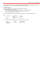
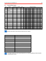
6.1 Defined alarm types and alarm reasons . . . . . . . . . . . . . . . . . . . . . . . . . . . . . . . . . . . . . . . . . . . .
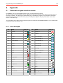
6.1.1 List of alarm types . . . . . . . . . . . . . . . . . . . . . . . . . . . . . . . . . . . . . . . . . . . . . . . . . . . . . . .
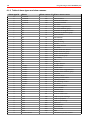
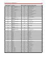
6.1.2 Table of alarm types and alarm reasons . . . . . . . . . . . . . . . . . . . . . . . . . . . . . . . . . . . . . .
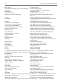
6.2 SIAS Components . . . . . . . . . . . . . . . . . . . . . . . . . . . . . . . . . . . . . . . . . . . . . . . . . . . . . . . . . . . .
..............................................
6.2.1 SIAS commands
6.2.2 SIAS variables
........................................................
6.2.3 SIAS-Konstanten . . . . . . . . . . . . . . . . . . . . . . . . . . . . . . . . . . . . . . . . . . . . . . . . . . . . . . . .
6.2.5 SIAS controls . . . . . . . . . . . . . . . . . . . . . . . . . . . . . . . . . . . . . . . . . . . . . . . . . . . . . . . . . . .
6.3 List of defined users . . . . . . . . . . . . . . . . . . . . . . . . . . . . . . . . . . . . . . . . . . . . . . . . . . . . . . . . . . .
6.4 System protocol types directory . . . . . . . . . . . . . . . . . . . . . . . . . . . . . . . . . . . . . . . . . . . . . . . . . .
174
174
174
175
179
179
183
185
186
188
189
7.
Notes . . . . . . . . . . . . . . . . . . . . . . . . . . . . . . . . . . . . . . . . . . . . . . . . . . . . . . . . . . . . . . . . . . . . . . . . . . . 192
4.3
Programming manual WINMAG plus
5
Introduction
Copyright 2008 Novar GmbH. All rights reserved.
The software described in this manual is furnished in accordance with Novar GmbH terms of business. It shall only
be used and copied in accordance with the provisions of this licence. No part of this publication may be reproduced
or transmitted in any form or by any means, electronic or mechanical without the written permission of Novar GmbH.
The information contained in this manual can be updated by us at any time without prior notice and shall not be
regarded as binding. Novar GmbH accepts no obligation or liability should errors or inaccuracies occur in this
manual.
We would like to point out that, in spite of extensive tests, we cannot guarantee faultless functioning in your system
due to the numerous hardware manufacturers and the possible resulting hardware configurations.
WINMAG plus is a trademark of Novar GmbH.
IBM is a registered trademark of International Business Machines Corporation.
Windows 2003, Windows XP, Windows Vista and Microsoft are registered trademarks of Microsoft Corporation.
All other mentioned products are trademarks of the respective manufacturer.
All rights reserved. Adobe, the Adobe logo and the Acrobat logo are all registered trademarks of Adobe Systems
Incorporated.
The WINMAG plus-Documentation consists of the following documents:
‚
‚
‚
‚
‚
the Installation instructions (P03126-26)
the Operating instructions (P03126-03)
the Operating instructions for WINMAG Lite (P03128-03)
the Programming manual (P03126-05)
Lists of the i/o devices and tables for WINMAG plus (P03126-24) with
tables of the types of i/o devices, symbols, alarm types,...
Additionally there are special Honeywell lists available with connectable components.
Symbols
This manual contains the following symbols that refer to sections of special importance:
Denotes important information on procedures and warns against steps that have serious
consequences.
Denotes important information on a particular issue and other useful information.
Denotes important information on the installation.
Tips on programming/installation as per the directives of the German Association of Property
Insurers.
6
Programming manual WINMAG plus
1.
General
1.1
What is WINMAG plus
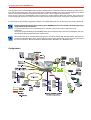
WINMAG plus is a modular PC-based security management system for hazard detection systems that can be
configured as per your requirements
‚
Running under the operating systems WINDOWS 2000 (up to version 1.xx), WINDOWS 2003,
WINDOWS XP professional and Windows Vista (from version 2.xx on).
‚
Innovative, convenient and configurable user interface
‚
Alarm processes and alarm conditions that can be adapted to your requirements
‚
With macro functions
‚
Flexible, windows-orientated graphics
‚
A variety of user entitlements
‚
Configurable as single or multi-user system or as a distributed system
‚
With connection of peripherals via PC interfaces, PC networking and modems(analog and ISDN).
‚
With “open” interface to different systems
‚
With connection modules to third-party products (central units, video matrix switches, building
services management systems) .......
‚
Connection to third-party products can also be executed by user.
WINMAG plus offers convenient, uniform, PC-based operating and control of the alarm systems connected including
message evaluation, alarm signalling and message processing that can be adapted to your requirements.
WINMAG plus runs as a single-user system on one PC or PC-Network with TCP/IP.
WINMAG plus can process data from various networks such as the Honeywell IGIS network, the Honeywell IGIS
loop network, the event protocol, the essernet, modem networks and output data that can be individually configured:
- Graphics with dynamic symbols
- Tables
- Individual program processes (e.g. alarm program)
- Output at several printers
- Logging in database and files
WINMAG plus data are stored in a protected, coded database.
WINMAG plus incorporates a global editing environment and a variety of examples.
Programming manual WINMAG plus
7
The operating mode of the WINMAG plus system is based on data received from linked networks, modem or from
PCs and the comparing of the data received with those conditions stored in the system. All messages are provided
with an unambiguous address created from network number, device address and I/O device.
Every device is given an unmistakable name as well as an evident address within the network. The I/O devices
incorporated in the system are numbered in accordance with a fixed schema and can be given configurable names.
If a message received fulfils a triggering condition, an individual program can be started to process the message.
A basic requirement for the programming of the WINMAG plus control software is knowledge of the
components to be connected.
To prevent input errors, we recommend you to compile a precise list of the components to be
connected.
As the free programmability of the WINMAG plus control software offers numerous possibilities, the user
should clearly specify implementation requirements.
We assume that you are familiar with using your PC as well as working with Windows 2003, Windows XP
professional and Windows Vista. If this should not be the case, please refer to your PC user manual and
the user manuals for Microsoft Windows Windows 2003 / Windows XP / Windows Vista.
Configuration
8
1.2
Programming manual WINMAG plus
Why WINMAG plus?
WINMAG plus unites different systems under one user interface.
As WINMAG plus unites different systems under one user interface, the operation and the monitoring of
individual components is highly simplified. The user does not need to have detailed knowledge of the
components connected.
Configuration of the control program can be executed as per user requirements.
All components can be monitored and operated consistently.
WINMAG plus displays messages and alarms as per user requirements
Messages and alarm inputs can be displayed as per user requirements. Depending upon requirements,
texts, graphics (with symbols), tables or mixed output can be programmed. Selection screens can be
configured in interactive mode so that detailed information or functions can be selected during processing.
The triggering of an alarm can be exactly located by way of symbols included in the graphics (configured
as per user requirements). Two user actions can be allocated to each symbol (left/right mouse buttons).
One action can perform of numerous commands.
WINMAG plus supports the user
Thanks to configurable processing routines, the program can be optimally adapted to user requirements i.e.
starting from simple and self-explanatory processes up to complex interactive processes (depending on user
logged on). Thus, optimal support of the user is achieved thanks to clear and authorization level appropriate
instructions.
WINMAG plus controls
WINMAG plus controls components. Thereby, control can be limited (user and time).
Examples:
• Switching detectors on/off
• Switching cameras to monitor display
• Resetting alarms
• The control of components via potential-free contacts (hardware necessary).
Control can be executed either in interactive mode or automatically
WINMAG plus monitors
WINMAG plus can check whether settings are as per requirements and reacts
accordingly.
WINMAG plus collects data
WINMAG plus saves data with respect to all actions executed by the management
system. You can evaluate this data (defined period of times)
WINMAG plus distributes data
As a multi-station system, WINMAG plus can transfer alarms/messages to other
computers. WINMAG plus can transfer alarms/messages to clients as an
InternetServer (special WINMAG plus version necessary).
Programming manual WINMAG plus
1.3
9
WINMAG plus versions
Depending on version, WINMAG plus can be operated with different options. It is possible to change the
versions and to change the options.
1.3.1 Demo version
The demo version gives you an overall picture of the WINMAG plus performance capabilities. The demo
version permits unlimited operation (20 days for max. 8 hours each) as single-station or multi-station version
with all options. Networks can be connected and messages/alarms processed. All editing functions are
enabled.
To enable demo operation without sensors and far-reaching knowledge of the system, demonstration data
are available that can simulate different types of alarms for demonstration purposes. Hereto, please refer
to the menu “Table view”, option “Simulation” for simulating alarms/messages.
After online operation of the demo version 20 test days, you can still use the demo version for editing and
simulation via the menu option “Simulation”. After the demonstration possibility of online operation has
elapsed, online operation is only then possible when you have a licence (dongle necessary).
The CD also contains the WINMAG -Lite program, the inexpensive starter version for one object (network)
with a maximum of 500 I/O points. Demo-version limitations in WINMAG-Lite are identical to those in
WINMAG plus. An inquiry as to whether WINMAG plus or WINMAG-Lite should be installed is generated
during installation.
1.3.2 Single-station version
The single-station version permits the operation of WINMAG plus at one time at one station. Programming
and data environment is identical with the demo version.
Optional rights and upgrade number are acquired when licensing (dongle). This number is required for
extending and upgrading WINMAG plus.
Several single-station licences can be operated in an IGIS (or Essernet) network. These are then
autonomous to a large degree and thus enhance redundant reliability of the system.
Every PC can be configured to individual requirements and execute different functions.
Using the WINMAG plus “Access Control” option or the “MultiAccess for Windows” option “process
visualization” is possible using the access control software “IQ-MultiAccess” and “MultiAccess for Windows”.
1.3.3 Process Visualization
“Process visualization” is a version of WINMAG plus with reduced spectrum that cannot communicate with
an intrusion detection central unit or a fire detection central unit. This version works together with “IQMultiAccess” and “MultiAccess for Windows” and serves for
‚ display of graphics (door states /zone counters)
‚ output of door data and the names of persons in a zone
‚ integration of flexible alarm processing (access control).
1.3.4 Multi-station version
The multi-station version permits the distribution of alarms/messages/signals via a PC network. One or more
computers can be assigned as a server and other computers (clients) can request data.
Prerequisite: Set-up of a TCP/IP service.
The number of connections is not logically limited. Practical limits are set by computer and network
performance.
10
Programming manual WINMAG plus
3 modes of multi-station configuration are available
1.3.4.1 Multi-station
One or several computers act as server that supply alarm/message data to other computers (also interactive). Multistation includes network distribution of messages via the event protocol. In addition the data environment is shared.
Every client replicates its own data environment with that of the server and copies changed server data into its own
data environment. The default WINMAG plus directories are checked. Data not included in the WINMAG plus
default directories are not automatically copied.
The computers from which data are supplied are defined at the client. All changed or new data (default directories
e.g. database, graphics from the “Graphics” directory, layers, SIAS programs) are transferred from the server to the
client. Changing of the alarm point list and to the network structure cannot be executed by the client.
The WINMAG plus directory on the server must be enabled for sharing.
The WINMAG plus directory on the server must be mapped to a drive on the client.
The path to the server WINMAG plus directory is defined in the start parameters of the client WINMAG plus
WINMAG plus runs on the server and on all clients locally!
Example:
WINMAG plus is running on the server in c:\programs\WINMAGplus
The server is connected to the client computer using a drive mapping of N://c:programs\WINMAGplus:
A shortcut is created (client) that has the destination:
C:\<path to local WINMAGplus>\WINMAG.exe -c n:
The client checks its data with the data on the logical drive n: in the directory program
programs\WINMAGplus.
The path is prompted with “-c”.
Prerequisites
‚
‚
‚
‚
‚
‚
‚
‚
‚
The WINMAG plus directory must be enabled for sharing at the master.
The client must have read-access to the master directory.
A logical drive allocation (to the master) must be defined at the client.
The client computer must be defined as multi-station client at the master.
A TCP/IP connection must exist between master and client.
The host address or the IP address of the client must be defined at the master.
Multi-station option and dongle are necessary at “distributed” computers.
The same WINMAG plus version must be installed on all computers.
A dongle incl. multi-station option must be available (master), incl. number of connected computers.
Error messages:
‚ Update program
When a check of the programs in the main directory (master/client) has been executed, a difference
has been recognized. Master and clients must be equipped with the same program versions.
‚ Update data
Stack content or data are not identical and cannot be automatically updated
(e.g. from sub-directories that have been self-created).
‚ During updating of data (master directory) an error has occurred.
The check cannot be executed. Possible reasons:
- data write-protected?
- access to data (other programs) attempted?
Programming manual WINMAG plus
1.3.4.2
11
Distributed network
The “distributed” mode is a variant of the multi-station mode. One or several computers act as server that supply
data to other computers (also interactive). Contrary to the multi-station configuration, every computer has its own
data environment; database and alarm programs can be configured as per requirements. The database and SIAS
programs (master) are not copied.
The server can supply messages/data that it has initialized/requested (network), i.e. all data requested by the client
must be available at the server.
Example:
WINMAG plus is running on the server in C:\programs\WINMAGplus.
On the client computer, WINMAG plus is to be found under c:\”path to local WINMAGplus”.
A shortcut is created at the client that has the destination:
C:\<path to local WINMAGplus>\WINMAG.exe -c
The client is started using the start parameter “C:\ ......” (without specifying path) as with multi-station
mode.
Prerequisites
‚ The client must be defined as a „distributed system client“ at the master in the network configuration.
‚ A TCP/IP connection must exist between master and client.
‚ The host address or the IP address of the client must be defined:
• at the master for the client
• at the client for the master
‚ Multi-station option and dongle are necessary at „shared computers“ (in other words not at a client
that only receives data).
‚ All computers possess an own database with own data structure. E.g. If a computer is linked to an
IGIS network, alarms/messages/signals can be distributed to other computers via the event protocol
by entering an event protocol address in the network configuration of the network under „data
transmission. The network to be transmitted is assigned to the „shared system client“. The
messages can be received in an “event network” at the client.
‚ Different WINMAG plus versions can exchange data.
1.3.4.3
Several Single-stations versions in a network
Several Single-station computers are operated in an IGIS network. Every computer has its own unique IGIS
address. All other data may be identical or different. The computers can be programmed for “computer
interaction” via configuration of triggering conditions. As several computer possess their own network access
feature, the redundant design enhances system reliability.
Numerous different initialization models can be kept in central units. As every computer has its own initialization
model, the number of initialization models corresponds to the number of computers (multi-station or shared
systems need only one initialization model for all computers connected) linked directly to the central unit.
12
1.4
Programming manual WINMAG plus
Licensing/Dongle
To use WINMAG plus permanently, the program must be licenced. Licensing enables program options and
authorizes you to use the program.
Upon licensing WINMAG plus you receive a dongle that is to be connected to a parallel interface or a USB port
of the WINMAG plus computer. For multi-station systems, every computer that includes connections needs a
dongle. Workstations without own connection do not need a dongle.
Licensing is for a specific version. When upgrading to a higher WINMAG plus main version (change of first
figure e.g. from V01.x to V02.x) , the licence must be upgraded to the current version.
If the dongle is removed when the program is in operation, WINMAG plus runs for max. 72 hours in online
operation without the dongle.
If you do not licence WINMAG plus, after installation it will run for 20 optional online test days (8 hours each
time) as full version and then it will switch into demo mode. This means, that after the demonstration time has
elapsed, no connection is available to components.
A start in offline mode does not reduce the number of online test days.
The demo version of WINMAG plus is an executable editing environment. All components (except the adoption
of alarms/messages) function. Thus, any event can be simulated using the demo version. All edit functions can
be used.
How to licence WINMAG plus
Licensing is executed of the ordering of a dongle and a licence file. The licence includes individual specifications
and enabled options.
The following specifications must be known for licensing:
‚ Name of customer
‚ New licence, update, upgrade
‚ Type of dongle (parallel or USP port)
‚ Connection structure (=> number of dongles, options)
‚ Update number.
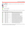
Program options to be ordered (per dongle and licence file):
Licence WINMAG Lite
O
Licence Intrusion
O
Licence Fire
O
Licence Access control
O
Licence Video technology
O
Licence Rescue route technology/escape door controller
O
Licence ConnectionServer
O
Licence WINMAG plus RDT
O
Licence OPC server
O
Licence OPC client
O
Licence Notification
O
Licence Escalation
O
Licence DTMF control possibilities
O
Licence Client processing ability
O
Licence WEBX
O
Licence DEZ
O
Licence Redundancy
O
Licence Multimonitor
O
Licence Auto Cad Integration
O
Licence OEM
O
Licence WINMAG plus client
- number of stations to which data are distributed
Programming manual WINMAG plus
13
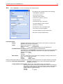
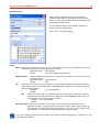
1.4.1 Licensing information
Licence parameters are displayed in WINMAG plus in the info dialogue using the "Help / Info about WINMAG
plus" menu.
The executable full version and the demo version are identical. You do not have to replace programs to turn a
demo version into a full version. The sole difference is the dongle and licence file.
The file "LIZ_XXXXXXXXXX.txt" contains a list of all licence parameters.
During installation or when updating, WINMAG plus loads this file into the WINMAG
plus master directory.
If WINMAG plus does not detect the dongle, you have to enter the port of the
dongle. Without detecting the dongle WINMAG plus only starts in the demo
mode.
Examples:
1.5
USB-Port:
c:\programs\WINMAGplus\winmag.exe /Hardlock USB
LPT1-Port:
c:\programs\WINMAGplus\winmag.exe /Hardlock 378p
LPT2-Port:
c:\programs\WINMAGplus\winmag.exe /Hardlock 278p
Ordering WINMAG plus
WINMAG plus is a modular program, thus the WINMAG plus software comprises several part numbers.
To help you configure your WINMAG plus software components, please use our WINMAG plus Order Form
which you can request from our Sales Department.
This form specifies the ordering data and licence data mentioned so that you can easily send the order to us via
telefax +49 (0) 2137-17-6076.
For further information on our Order Form, please phone +49 (0) 2137-17-6075.
If you require the WINMAG plus basic version, you must order Part-No. 013610.
Depending upon the peripheral devices connected, you will also require one or more program options e.g.:
013601 WINMAG plus licence EMZ
(intrusion)
013626 WINMAG plus licence BMZ
(fire)
013603 WINMAG plus licence ZK
(access control)
Every PC that distributes data needs a dongle that includes the required options and number of computers to
which data can be transferred.
013630 basic licence with dongle for the parallel interface
013631 basic licence with dongle USB
You need a client licence for every computer to which data is re-transmitted (e.g. re-transmit to
3 computers = 3 client licences):
013625 licence WINMAG plus client
You can order program options separately to upgrade your basic program. For every change of option you will
receive a licence update file "LIZ_XXXXXXXXXX.txt”. This update/upgrade file must be loaded into the
WINMAG plus update directory.
An old version of WINMAG plus can be updated to the current program version. Please note that the licence
applies to a specific version.
As a rule, a revised licence is required when changing the version (update "LIZ_XXXXXXXXXX.txt" file). If you
wish to change from a WINMAG version up to 5.0 to the current WINMAG plus version, you require a dongle for
every computer that is connected to WINMAG components.
013616 Upgrade of a WINMAG installation from Version 6 to the latest WINMAG plus version
013617 Upgrade of a WINMAG installation up to Version 5 to the latest WINMAG plus version
013636 WINMAG Lite upgrade to WINMAG plus full version
14
Programming manual WINMAG plus
2
System requirements
2.1
Operating system
WINMAG plus runs under the following 32-bit operating systems:
- Microsoft Windows 2000, SP4 (up to WINMAG plus Version 1.xx)
- Microsoft Windows 2003
- Microsoft Windows XP Professional, SP2
- Microsoft Windows Vista (from WINMAG plus Version 2.xx)
(Pay attention to the special advices in the Installation Instructions P03126-26)
2.2
SOFTWARE requirements
Your computer must be equipped with the following:
- Internet Explorer Version V5.0 or higher
2.3
PC requirements
To permit WINMAG plus to run at an adequate speed your PC should fulfil the following requirements:
- PC/laptop, IBM-compatible, min. Pentium / 3000 MHz or Dual Core
- 1 GB RAM
- Min. 1 GB disk space
- SVGA / XGA graphics board with 4 MB video memory
- Monitor with a resolution of min. 1024 x 768 pixel
- Mouse, trackball or other Windows compatible pointing device
- WINMAG plus software incl. necessary options
- Sound board with external loudspeakers (necessary for sound output)
- parallel / USB interface for dongle / printer
With IGIS direct connection:
- IGIS connection cable for the linking of a PC to the IGIS network
- IGIS-PC plug-in board (Article No. 013301) at ISA bus (not available in all computers)
- IGIS-V24 -PC-interface
With Essernet connection:
- serial interface for connection of the Essernet interface
With modem connection:
- Modem at PC (internal / external, analog und/or IDSN)
With multi-station systems:
- PC-Network adapter card
- the TC/IP protocol must bet set-up.
With Video overlay
- video card
With video drive (conventional):
- serial interface for connection of the video matrix switcher
- associated video driver
With video drive (digital):
- connection on recorder or *view
Please make sure that your computer capacity suffices for the program and that
- no energy save modes are active (e.g. deactivate disks)
- avoid the parallel use of programs that require a high amount of resources
Caution with Windows XP
It can happen that GDI objects are not enabled with the WINDOWS XP operating system and the
system is troubled as a result. It is imperative that the following be realised to avoid this:
- The classic display screen must be set
(Start/Settings/System control/Display/Designs/Windows classic) or
- The visual designs should be deactivated in the WINMAG plus link
(Properties/Compatibility/Display settings/Deactivate visual designs) or
- the following WINDOWS-Patch must be installed (pay attention to the language when downloading):
http://www.microsoft.com/downloads/details.aspx?familyid=9B5EDFC8-A4BB-4080-90636518166E2DAB&displaylang=en
Programming manual WINMAG plus
3
15
Connections to WINMAG plus
WINMAG plus can communicate with components in a variety of ways.
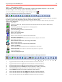
The following interfaces are possible:
Direct connection to serial interface of the central control unit
Interface via the Honeywell IGIS network (PC card / V24 / loop)
Interface to modem
Interface via the Honeywell event log
Interface via “essernet”
Interface via connection to hardware (linkable central control units)
Interface via the Honeywell connection server
Interface via the Honeywell OPC server
Interface to an OPC client
WINMAG plus has an open structure that is highly suitable for the connection of third-party components. Thus,
many non-Honeywell components are connected to WINMAG plus via the above-mentioned ways.
Novar GmbH will be pleased to be of your assistance for creating connections. Above all, the ConnectionServer
is available for creating a relatively easy connection.
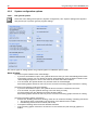
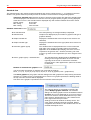
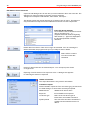
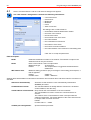
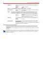
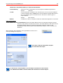
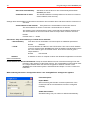
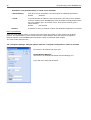
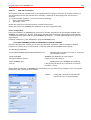
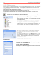
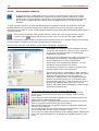
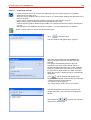
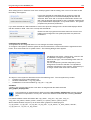
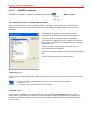
3.1
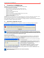
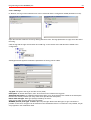
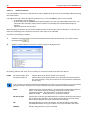
Application configuration incorrect
If WINMAG plus or a WINMAG plus driver is installed on a network, the following message may appear:
The operating system WINDOWS provides security guidelines for network drives that have the
same effect as a blocking function. This means that programs (exe-files) can only be started by
other computers within networks after the relevant security guideline has been deactivated. This
can in turn only be deactivated by Administrator rights.
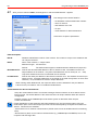
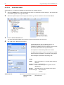
Deactivate security guideline :
Find the Caspol file on the WINMAG plus drive. The file usually appears more than once. To deactivate the
security guideline, you require the following path X:\WINDOWS\Microsoft.NET\Framework\v2.0.50727 (X:
stands for the drive on which the operating system is installed).
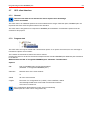
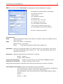
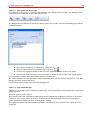
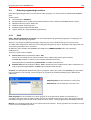
First start the command line run in the windows start window,
and confirm with OK.
In the DOS window that then appears, navigate to the path:
X:\WINDOWS\Microsoft.NET\Framework\v2.0.50727\ and
enter the characters in the following order:
Note: Pay attention to small/block letters!
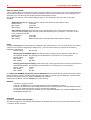
caspol -machine -addgroup 1. url file://W:\* FullTrust
(W: stands for the connected WINMAG master drive)
Press the “Enter” key to confirm deactivation of the security guideline for this computer. WINMAG plus or the
corresponding exe-file can now be started.
Deactivate the security guideline for each computer separately.
(See also “Edit Online”)
16
3.2
Programming manual WINMAG plus
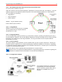
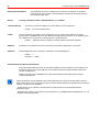
Connection to the IGIS network
3.2.1 IGIS-Loop connection
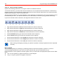
The connection of a PC/laptop to one or more IGIS-Loop networks is executed via the IGIS loop controller (Item
No. 013330.10, 013331.10 in housing ZG0, 013332.10 in housing ZG2). Parameter values are set at the
controller via micro switch and the “IGIT” program (e.g. defining of the ring bus address = loop number, ring bus
sub address = loop controller address.
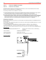
The interface is connected to a PC serial interface using a 1:1 cable.
The IGIS-Loop software version V01.00 can only be executed with the V24 connector version VO2.00.
The V24 connector version VO3.00 or higher requires at least the IGIS-Loop software version P02.02.
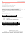
Serial connection to PC
cable 1:1 , 9 pole connector
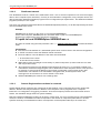
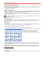
(Left) IGIS-Loop connections (Right)
2 retrogade, decoupled RS 422 paths
The ring cable is a 4-wire (twisted pair) cable. When connecting to components, please observe correct
direction (i.e. left output to right input and vice-versa) between the controllers.
Every loop has a unique address, the ring bus address (in example 0). Every controller has a unique ring bus
sub-address. The 3 address parameter (IGIT) refers to the K-bus address of the controller. This 3rd address
must not be set in WINMAG plus.
Programming manual WINMAG plus
17
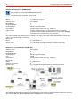
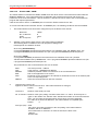
3.2.1.1 User address allocation within the security network IGIS-LOOP
So as to be able to address every user
within the network it must be positively identified. Identification is executed using the “user address”. This user
address is input into the respective system component of the hazard detection system as a 3 byte address.
The user address is comprising:
•
Ring address
•
Ring sub-address
•
Device address
Address - ring sub address (street)
Device address (house number)
3.2.1.1.1 Ring address
Address of the ring in which the user is available.
The ring address can be compared with the
specification of a “town”.
3.2.1.1.2 Ring sub-address
So as to clearly identify a group of devices (e.g. fire detection computer, operating unit) branching off a ring, a
ring sub-address is required. The ring sub-address designates a stub line branching off from a ring. Every stub
line leaving a ring must have its own ring sub-address. The ring sub-address can be compared with the
specification of a “street”.
3.2.1.1.3 Device address
The “device address” clearly identifies a device available within a group of system components. Thereby, the
respective system components (e.g. remote operating unit) could all be installed on one stub line. Depending
on complexity, the device address could also be an individual component (e.g. computer pcb of a fire detection
computer) of a hazard detection system.
The device address can be compared with the specification of a “house number”.
Please refer to the respective Installation Manual or Programming Manual for restrictions regarding the
allocation of addresses and for information on “reserved” device addresses.
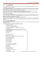
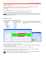
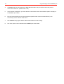
3.2.1.1.4 Configuration example
The example illustrates the configuration
and networking of an IGIS loop network
with fire detection computer FDC 1024-G,
MB 100 and a WINMAG plus control
software.
18
Programming manual WINMAG plus
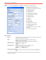
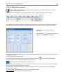
Network configuration in WINMAG plus:
An IP address or a host name must have been assigned to the computer in the network configuration
(see Chapter 4.2.2.3.2 Edit WINMAG plus stations).
A network must be created for every node.
Network for ring subaddresses 0/1 (FDC1024):
Name:
e.g. IGIS loop 0 node 1
Address of PC:
251 (default)
Ring address:
0
Ring subaddress:
1
Virtual address:
Adopt suggestion (9000)
Port:
Serial
Port address:
Serial interface used at PC (e.g. COM1=1)
Type of driver:
TCP/IP enables drivers to be performed on other computers.
TCP/IP must be installed. Shared memory can be used if WINMAG
plus and driver are executed on one computer.
The central control unit is inserted in the network as an object. Select the newly created network “IGIS loop 0
node 1” and insert an object “FDC1024”.
Object data:
Name:
e.g. FDC 1024 0-1
Address of end unit:
0 (=central computer)
Access code:
e.g. 12345678 (as programmed in the central control unit)
Network for ring subaddress 0/2 (MB 100):
Name:
e.g. IGIS loop 0 node 2
Address of PC:
251 (default)
Ring address:
0
Ring subaddress:
2
Virtual address:
Adopt suggestion (9001)
Port:
Serial
Port address:
Serial interface used at PC (e.g. COM1=1)
Object data:
Name:
Address of end unit:
Access code:
e.g. MB 100 0-2
8
e.g. 1232456 (as programmed in the central control unit)
The example illustrates the configuration and networking of two IGIS loop networks with fire detection computer
FDC 1024-F, MB 100, MB256, BMS8008 and a WINMAG plus control software.
Programming manual WINMAG plus
19
Network configuration in WINMAG plus:
An IP address or a host name must have been assigned to the computer in the network configuration
(see Chapter 4.2.2.3.2 Edit WINMAG plus stations).
A network must be created for every node.
For mixed configurations with central control units of series 8008 and HB- and/or MB-units the
adresses of the PC's must be >31.
Network for ring 0 as in example 1:
Network for ring subaddress 1/0 (MB256):
Name:
e.g. IGIS loop 1 node 0
Address of PC:
2
Ring address:
1
Ring subaddress:
0
Virtual address:
Adopt suggestion (9002)
Port:
Serial
Port address:
Serial interface used at PC (e.g. COM2=2)
Type of driver:
TCP/IP or shared memory
Object data:
Name:
Address of end unit:
Access code:
e.g. MB 256 1-0
8
e.g. 12345678 (as programmed in the central control unit)
Network for ring sub address 1/1 /BMS8008):
Prerequisites:
Ring address:
Ring subaddress:
Virtual address:
Port:
Port address:
Type of driver:
IGIS loop controller from V03, Essernet-compatible central control unit software, IGIS
loop micromodule for Esser central control units)
e.g. IGIS loop 1 node 1
2 (all ESSER components in an IGIS loop system must be configured with an address
from 1 to 32 consecutively. If e.g. address 1 has been assigned to the central control
unit and there is no further ESSER central control unit in the loop, the PC must be
assigned address 2.
1
1
Adopt suggestion (9003)
Serial
Serial interface used at PC (e.g. COM2=2)
TCP/IP or shared memory
Object data:
Name:
Address of end unit:
Access code:
e.g. BMS 8008 1-1
1
0
Name:
Address of PC:
One IGIS loop driver is started for both loops.
20
3.3
Programming manual WINMAG plus
Dial-up connection
WINMAG plus can communicate with remote systems and remote networks via modem. Both (also distributed)
analog and ISDN modems are supported. To permit modem connection, the following requirements must be
fulfilled:
! Modem installed and setup (PC) as per mode of connection (analog/ISDN).
! Component or network must be equipped with modem (DGA 2400/DS7500).
! Configuration of the object in WINMAG plus via “Remote network”.
! RemoteServer must be installed and started.
Installation of the “RemoteServer” may be executed when you install WINMAG plus and select “RemoteServer”.
You can also install the RemoteServer at a later date by restarting the installation of WINMAG plus. To do this,
you must select the option “Edit program” and activate the check box “RemoteServer” included in the server
dialogue box.
RemoteServer is required for establishing connection and must be started before WINMAG plus is started.
We recommend considering the filtering of data for data transfer as:
- the transfer of data via the telephone network is subject to fee
- data transfer rate (especially analog transfer) via modem is limited
3.4
Event protocol connection
The default data communication protocol between WINMAG plus and other applications such as MultiAccess,
RemoteServer, video servers, escape route connection or other WINMAG plus work stations is the Honeywell
event protocol.
The event protocol permits the protected, monitored transport of alarms/messages via computer-internal routes
or computer networking.
! The computer-internal network uses a “shared memory” driver.
! The PC network uses a TCP/IP driver. Hereto, a computer network must exist and the computers must be
equipped with TCP/IP.
Networking is executed by way of the allocation of unique “virtual addresses” to every component used.
Components are the individual PCs and the networks to which data is transferred.
The drivers for using the event protocol are installed together with WINMAG plus.
A corresponding option must be obtained for using this connection.
Examples of options:
Art. No. 013603
option access control
Art. No. 013604
option video technology
Art. No. 013605
option escape route
Art. No. 013625
option WINMAG plus client
3.5
General connection via the ConnectionServer
The ConnectionServer facilitates the creation of drivers for the connection of third-party products to WINMAG
plus.
It is like a shell that facilitates the viewing of the event protocol. It encapsulates the event protocol transactions
(communication from drivers to WINMAG plus) and supplies a simple programming interface applying only a
few instructions. Conversion for the connection of third-party products must be executed individually. You can
obtain an interface description for the ConnectionServer that includes error codes from an actual connection
example and the instruction structure. If you procure the ConnectionServer Developer Kit, Art. No. 013607 you
have also obtained 1-2 days Honeywell support.
Examples for the connection via the event protocol (please refer to EP configuration for description)
Honeywell:
Other:
FTServer 925, UltiAccess from V2, RemoteServer for modem connection, V24Conn. Video
Matrix Switchers, Honeywell Maxpro 32, Philips, Ernitec, Esser 5008, Essernet (from 2001), ..
Third-party drivers offered by Honeywell clients for connection to EIB, Siemens, Cerberus etc. Please
feel free to contact Honeywell for more information on drivers.
Programming manual WINMAG plus
3.6
21
Interface via OPC server
3.6.1 General
The use of the OPC server and the OPC client requires basic knowledge of OPC and DCOM.
OPC is the abbreviation for “OLE for process control”. OPC is a standardized OPC foundation software
interface for exchanging process data between applications. OPC is based on the Microsoft COM/ DCOM
technology. DCOM enables access via a network. OPC is in the process of becoming established as the
standard data interface in automation technology. The WINMAG plus OPC server is a additional option that can
be enabled via the dongle. This option enables the use of WINMAG plus as an OPC server. The WINMAG plus
OPC server is integrated in the WINMAG plus installation as a component. When queried by a client, the OPC
server provides no data without being enabled. In offline mode, data are available for test purposes.
For connection purposes, WINMAG plus can be operated in a mode without an interface so that WINMAG plus
components are only applicable to the user during configuration or in case of an error. The WINMAG plus
interface is controlled via the file “options.ini” in the WINMAG plus master directory. If the file exists, the
following setting is possible:
[OPC]OPConly = true
reduced interface for OPC operation only.
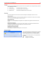
3.6.2 Use of the OPC server
An OPC data access server is a software package, that provides other programs (OPC clients) with process
data according to defined (fixed) regulations (OPC specification). OPC data access servers are mainly used as
a substitute for device drivers that would otherwise have manufacturer-specific interfaces. With random OPC
clients, it is then possible to exchange process data provided by the OPC server.
The OPC server is started automatically if this is requested by a random client. Several OPC clients can create
a connection simultaneously to the OPC server.
When the OPC server is actively connected with a client, you cannot exit WINMAG plus!
3.6.3
OPC interfaces
Not only the interfaces required according to the OPC specification Data Access 2.04, but also the browsing
interface is supported. This enables an OPC client to browse same without having knowledge of the address
space.
Browsing means requesting the existing address structure of an OPC server and enables the simple selection
of tags and communication with the tags without knowing the addressing syntax of the OPC server.
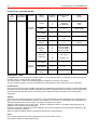
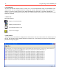
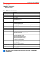
The following OPC connections are supported by the OPC interface:
supported OPC- Interfaces
OPC- DA 2.04
IOPCCommon
Required
IOPCServer
Required
IConnectionPointContainer (OPCServer)
Required
IOPCItemProperties
Required
IOPCBrowseServerAddressSpace
Optional
IOPCItemMgt
Required
IOPCGroupStateMgt
Required
IOPCSyncIO
Required
IOPCAsyncIO2
Required
IConnectionPointContainer (OPCGroup)
Required
22
Programming manual WINMAG plus
3.6.4 Display of WINMAG plus data types on OPC data types
In the WINMAG plus system, process variables are managed as enumators and can have max. 16 function
values. Description texts can be allocated to these discreet values. Access to the process values is via their
discreet value or the description text.
In the OPC server, the process values and the numerical values are also managed as texts. Allocation to OPC
data types is as follows:
Texts are always displayed on VT_BSTR
Numerical values are displayed on VT_Ul1.
- The statuses of an I/O point, objects or network are also displayed as a total
of 8 statuses (break down in Nibbel) as a VT_14 value (the value must be evaluated unsigned).
- The OPC clients enable mapping to all other supported OPC data types.
OPC access rights
The OPC access rights are displayed on the WINMAG plus variables as follows:
- WINMAG plus InTags have READ access
- WINMAG plus OutTags have WRITE access
Option: All OutTags are readable with read_write access.
This option is required should a client demand a read process before a write process. The read out values are
only fictitious, constant values and only exist so that the read request is fulfilled.
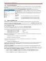
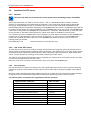
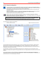
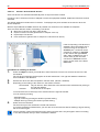
3.6.5 Address space structure
The address space uses the WINMAG plus address structure.
At the 1st level the configured networks appear.
At the 2nd level, the objects used for the network
appear. For every object the I/O points of the objects
are at the 3rd level.
The statuses are at the 4th level within the I/O points.
Depending on the type of object/network, statuses are
also possible at the 2nd or 3rd level (statuses of the
network/object). The statuses (max. 8) of an I/O point,
or network are also imaged as a total.
OPC tags are only allocated to the statuses and/or the
“total” of the statuses. All other structure elements only
contain information for addressing. The OPC tags
allocated to the statuses enable access to the discreet
process values and to the description texts allocated to
the values. For this purpose, an OPC tag is created for
representing the discreet values, a tag for the
descriptions and a tag per network or I/O point for the
“total” of the statuses.
Programming manual WINMAG plus
3.7
23
OPC client interface
3.7.1 General
The use of the OPC server and the OPC client requires basic knowledge
of OPC and DCOM.
The OPC client is an additional option that can be enabled via the dongle. With this option, WINMAG plus can
represent data from external systems with an OPC interface.
The OPC client is integrated as a component in WINMAG plus installation. Command line options must be
entered for this purpose.
3.7.2 Program start
The OPC client can only be started with command line options. If no options are entered, an error message is
transmitted. Options are as follows:
The network must be defined, before the client is started.
Invoking the client for the above-mentioned example and the standard WINMAG plus database path would thus
be as follows:
WMOPCClient.exe /DB “C:\Programme\WINMAG plus” /Netname “TestOPCClient”
Options:
/DB
Path for WINMAG plus configuration database
(Standard: “C:\Programme\WINMAG plus”)
/Netname
Network name of the event network
or
/NetID
ID of the event network
/CfgFile
File name of a configuration file (*.WOC). If this is defined, it will be
automatically loaded when started and communication with the
OPC server commences.
If the configuration file default.woc exists, this is automatically
loaded (see also 3.6.3.4 store configuration file).
24
Programming manual WINMAG plus
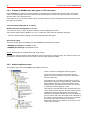
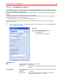
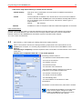
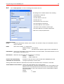
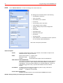
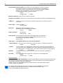
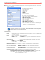
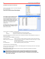
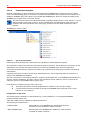
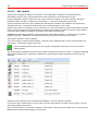
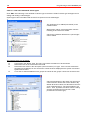
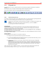
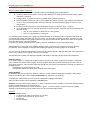
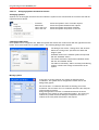
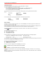
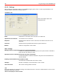
3.7.3 Configuration and operation
3.7.3.1 General
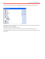
After starting the client, an icon appears at the right in the tool bar
.
This has a context menu (right mouse button).
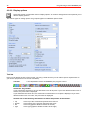
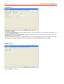
Click “OPC View” to display the main window:
Use the three tabs at the top to display different information windows:
Server
for finding OPC servers and entering
in the configuration
Browse for finding data points and entering
data points in the configuration
Config
for displaying and editing the current
configuration (data points, tags)
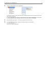
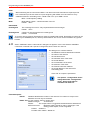
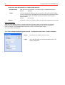
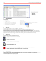
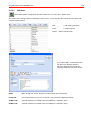
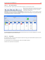
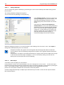
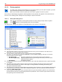
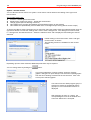
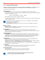
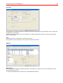
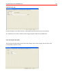
3.7.3.2 Add server
In the “server”, the branches of the displayed
tree are extended either under “Data Access
V1” or “Data Access V2”. These contain the
corresponding OPC server. This can be
added by clicking the desired server with the
right mouse button and selecting “Add
Server” in the context menu (only one server
is possible per client level).
Local OPC servers and those available in
the network can be used.
However, a corresponding Windows DCOM configuration is required for network servers (see also 3.6.3.9
common problems and restrictions).
“Browse” automatically appears.
Programming manual WINMAG plus
25
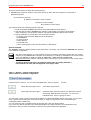
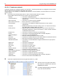
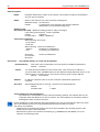
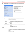
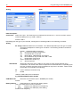
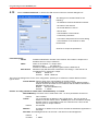
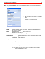
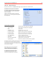
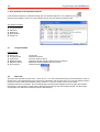
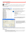
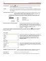
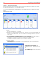
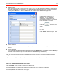
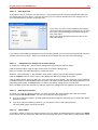
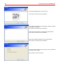
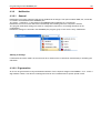
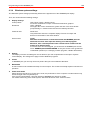
3.7.3.3 Add tags
In “Browse”, the tags of the selected server can be searched and the configuration added (illustration on left).
Open the branches under the server by clicking with the mouse. The tags (illustration on right) are at the end of
the string.
Click the tag with the right mouse button and “Add Tag” in the context menu and this will be added to the
configuration:
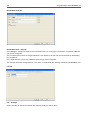
A dialogue window appears in which the parameters of the tag can be edited:
Tag path: The path of the tag in the OPC server (fixed)
Description: A random description, max. 40 characters text. Default is the tag path.
Additional description: An additional random description, max. 40 characters text. Default is the description
that the OPC server provides (not every OPC server provides the description).
Native OPC data type: Data type (fixed) provided by the server
OPC access rights: Access rights to the tag (fixed)
WINMAG plus I/O point type: WINMAG plus I/O point type. With some data types, a type conversion is
possible. In this case, the types can be selected in the combination field. If a conversion is not possible, only an
entry appears in the combination field.
26
Programming manual WINMAG plus
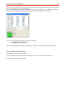
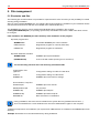
Added tags appear under the rubric “Items”. The tags can be edited per context menu (Edit Item) or deleted
(Delete Item).
3.7.3.4 Store configuration file
After the desired tags have been added, the disk symbol can be used to store the configuration. Two files are
created:
- DATEINAME.WOC
The actual configuration file (WINMAG plusOpcClient)
- DATEINAME.TXT
Import file for WINMAG plus
The .WOC file can be loaded at a later date in the client. If the .WOC-file is copied into the directory of the client
program under the name DEFAULT.WOC, this file is automatically loaded when the client is started and the
client commences communication directly.
The import file for WINMAG plus must be imported into the corresponding WINMAG plus network before
starting communication!
3.7.3.5 New configuration
This command is used to load a .WOC file that has already been created. Communication must be then started
manually.
Programming manual WINMAG plus
27
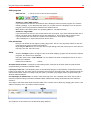
3.7.3.6 Start communication
Communication can now be started using the green symbol in the symbol bar. The symbol is then blocked and
a red symbol appears which can be used to interrupt communication.
During communication, the client displays values received by the OPC server and transmits these to WINMAG
plus in the correspondingly configured network.
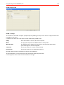
3.7.3.7 Global parameters
Select Global OPC Properties in the menu Action for setting two global parameters for the relevant
configuration:
Update rate:
Minimum actualisation interval of all data points in
milliseconds (ms).
Standard value is 1000ms = 1s
Deadband %: The maximum fluctuation for analogue values in percent
Default is 0.
An alteration is only signalled, if the value has changed by
at least the deadband.
28
Programming manual WINMAG plus
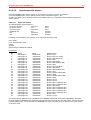
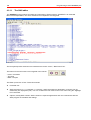
3.7.3.8 File format of configuration file
The .WOC file is a standard text file. This text file can also be edited manually. Individual data fields are
separated by semicolons. The data themselves must be enclosed in inverted commas.
Example:
OPCCFG-0100
"KiebackPeter.GLTserver.1";"";"1000";"4","10"
"1";"Z999.B000.G000.BI_F9999/1";"Binary Input 1";"300600002";"0"
"2";"Z999.B000.G000.BI_F9999/2";"Binary Input 2";"300600002";"0"
"3";"Z999.B000.G000.BI_F9999/3";"Binary Input 3";"300600002";"0"
"4";"Z999.B000.G000.BI_F9999/4";"Binary Input 4";"300600002";"0"
Structure:
First line
must contain OPCCFG-0100
Second line
Servername ; Node ; UpdateRate : max. I/O point no.; Deadband
Servername: The registered name of the OPC server
Node: The network name of the computer of a remote OPC server
UpdateRate: Update rate of the data point in ms
Max. I/O point no.: Number of the highest used I/O point during manual editing. MUST BE set correctly.
Deadband (optional): Deadband defined in percent, standard value is 0, value is optional to ensure backward
compatibility with previous configuration files
Further lines
Define tags and corresponding I/O points
I/O Point No. ; TagPath ; I/O Point name ; I/O Point type ; conversion (currently always 0)
I/O Point no.: I/O point no. for WINMAG plus
TagPath: The complete path for the data value in the OPC server
I/O Point name: Random name for the I/O point
I/O point type: Type of the I/O point (300600002 = binary input)
Conversion: For future use, should be currently set at 0).
3.7.3.9 Known problems and restrictions
Browse not possible
It may be possible that tags are not displayed in „Browse“ (the tree view has no elements). We are aware of this
problem and recommend re-starting the OPC client (store configuration beforehand, if required).
Remote server operation has not yet been thoroughly tested.
Solution: Operate the OPC client on the remote computer.
Programming manual WINMAG plus
4.
Programming WINMAG plus
4.1.
General
29
WINMAG plus is an open control software that can be greatly adapted to user requirements.
WINMAG plus includes all the tools necessary to execute adaption.
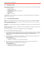
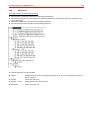
The editing functions are subdivided into
I. Internal editing functions
C System configuration (interface, networks, users, printer, rights...)
C Edit drawings (create image structure, integrate icons and actions)
II.
External editing functions
C Design alarm sequences (manage SIAS programs)
C Create/revise drawings
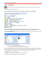
User-adaption is executed via an integrated programming language (SIAS). This programming language
operates within WINMAG plus in the same way as Visual Basic for Applications operates in Microsoft Office
applications.
WINMAG plus is supplied factory-configured with descriptions of Honeywell central units, objects and
procedures as examples for creating your own configuration.
You can use these examples for your own configuration purposes or remove them from the system.
In any case WINMAG plus must be adapted to the objects connected. This means that the detectors and
alarms/messages to be processed must be defined and can be user-adapted (Edit network configuration).
In order to configure, we recommend attending a WINMAG plus workshop or a special briefing to acquire
understanding of the system more quickly.
4.1.1 Programming procedure
The configuration of a WINMAG plus system is divided into the following steps:
1.
WINMAG plus installation
2.
Adapt data (edit)
Create networks, objects, I/O points
Adapt SIAS programs
Integrate graphics
Place icons
Adapt system settings
3.
Connect WINMAG plus with periphery
WINMAG plus is supplied factory-configured with descriptions of various central control units, networks and
objects, procedures and examples for creating your own configuration.
You can use these examples for your own configuration purposes or remove them from the system.
In any case WINMAG plus must be adapted to the objects connected. This means that the detectors and
alarms/messages to be edited must be defined and can be user-adapted (edit network configuration).
WINMAG plus system data is stored in a database. Thereby, relationships could exist between data that are
important for user-configuration. You should execute configuration changes in the same way as when building a
house i.e. hierarchical starting from the fundament.
30
Programming manual WINMAG plus
Data hierarchy of object data
Networks
in list
Network
Network
Object
Objects
I/O device
I/O device type
Status
Definitions
Function value
with alarm
reason and
user group
First of all the networks should be configured, then the objects and then the I/O devices with types (as per
structure).
Symbols can only be defined after I/O devices have been defined. A symbol is the graphical display of
an I/O device.
Programming manual WINMAG plus
31
4.1.2 Terms
Internal edit functions
Internal edit functions are integrated in WINMAG plus and can be directly called by WINMAG plus (user rights)
via menus and buttons. Examples of such functions are the creating of objects, the placing of symbols or the
issuing of user rights.
External edit functions
External edit functions are functions that cannot be directly called by WINMAG plus, these functions must be
pre-extracted from other programs or from system control. Examples of such functions are the creating of
graphics, printer configuration under Windows and the editing of SIAS programs.
Network
A network is a group of objects that are connected via a common interface/medium. For example, all control
panels connected to an IGIS-PC interface.
Object = control panel
Every device connected to a network is an object.
Examples of objects:
- Intrusion detection central units IDC 561-M20/M99/MB16/MB24/MB48/MB100/100.10/MB256/256 plus
- Fire detection computers FDC 664, BMC 616, BMC1024, BMC1016
- Frame interfaces for fire detection computers
- Operating and display unit ..
- IGIS V24 interface
- PC interfaces
Every object has a unique network address. Every message can be allocated to an object via this address.
I/O device
A I/O device describes a device who’s status can be monitored e.g. the status of a zone or the status of a
detector group.
A I/O device can have up to 8 states. I/O devices states can adopt defined function values.
I/O device status
Categorization of I/O devices into individual states, i.e. input states and output states.
Input = from object (central unit ) to PC = monitor
Output = from PC to the central unit = control
A maximum of 8 input states and a maximum of 8 output states can be defined.
Function value:
Function values are values that individual I/O states can adopt.
Example group 1 signal state 0
Function value 0: OK
Function value 1: triggered
Function value 2: not available
I/O device type
The I/O device type is the general description of a I/O device to which several I/O devices (same type) can be
allocated. Thus, the description of individual I/O devices can be kept to a minimum.
Example: The I/O devices 101 to 199 of a control panel type 561-MB100 are of the type “intrusion group
MB 100/16/8". The I/O devices are of the same type and must only be described once.
Variations can be derived from one type of I/O device that differ by way of changed:
- texts for status and function values
- alarm types
- filter structure (ie. Some function values and controls may be “filtered-out” by derived types)
A I/O device type and all types derived from it are known as an I/O device type family.
32
Programming manual WINMAG plus
I/O device type group MB 100/16/8:
I/O
device
No.
I/O device
MP-Name
Direction
Alarm
status
Function
value no.
Function value
Name
alarm
reason
101
Group 1
Input
0
status
0
1
2
OK
triggered
not available
Alarm
fault
(message
state)
1
Alarm.
0
1
out
on
Alarm group
2
int. disable
0
1
out
on
3
ext. disable
0
1
out
on
4
Tamper
0
1
out
on
5
allocation
Zone
0
1
2
3
Group
Group
Group
Group
6
allocation
Sub-zone
0
1
...
15
not in sub-zone
sub-zone 1
...
sub-zone 15
Output
0
int. disable
0
1
out
on
(Control
function)
1
ext. disable
0
1
out
on
2
clear
0
clear
Tamper
HptB 1
HptB 2
HptB 3
HptB 4
Alarm reason / type
In WINMAG plus you can allocate an alarm reason to every function value. A collection of alarm reasons form
an alarm type e.g. all fire alarms of the type fire.
The alarm reason is used in the default triggering conditions for the start of programs.
The type of alarm appears as tab in the stack view via which alarms of the same type can be separated.
I/O device list
The I/O device list for all IGIS capable components is published by Honeywell on request. It includes the default
I/O device types. These types include all possible I/O devices, statuses and function values of the components.
This list shows the data that can be received by each component and the data that can be sent by each
component.
Symbol
A symbol is the graphical display of a I/O device. Every status/function value combination can be allocated to a
layer. As there is an exact function value for every status of a I/O device, as many layers can be displayed as
statuses included in the I/O device type. The layers are drawn in the status
sequence and layered on top of each other. Thanks to transparent areas or optimally-configured layers, all
attributes can be simultaneously displayed.
Detectors are found in drawings by way of symbols - the proper functioning of the find function depends on the
correct positioning of symbols.
Select a symbol to display detector information and execute control functions.
Layer
One or more status/function value combinations can be allocated to a layer.
Every layer is drawn as independent image.
Programming manual WINMAG plus
33
4.1.3 Message structure
The messages transmitted by the system are based on the I/O device schema. Thus, an IGIS change message
has the following components:
•
•
•
•
•
•
•
Destination address
Message type /alarm type
IGIS address of the object (message address)
I/O device number
Status number
Function value number
Time
In WINMAG plus texts are allocated to all numerical data. All texts included in the system can be edited and
adapted to user requirements.
4.1.4
User-defined programming
In addition to freely editable system data, user-defined programs are the nucleus of the flexibility of WINMAG
plus.
Freely configured programs that include various tasks such as displaying data, controls, printing, checking etc.
can be called within WINMAG plus.
The programs are created in simple syntax (SIAS). WINMAG plus contains all tools to create and to edit these
programs.
Editing is executed using “SIASEDIT”. SIASEDIT is installed in the WINMAG plus program group during set-up
(External edit functions).
All user-defined programs are included in the WINMAG plus sub-directory “WINMAGEX”.
We differentiate between 3 different types of programs:
!
Stack programs that run as independent window. Start is executed via triggering conditions or via manual
program start. The program is included in the program stack and thus the execution sequence is defined
by way of own priority and other program stack content. A maximum of 10 programs can run
simultaneously.
!
Pop-up programs runs in a window via the polling window. The size of the window can be defined. The
program is immediately executed and is not placed in the stack.
Start is executed via:
C the triggering conditions or
C allocation to a mouse button or to a symbol (pop-up program)
!
Macro programs run in the background without a window, thus screen output is not possible. The
program is immediately executed and is not placed in the stack.
Start is executed via:
C the triggering conditions or
C allocation to a mouse button or to a symbol (macro) or
C the SIAS program instructions change, open, close
34
4.2
Programming manual WINMAG plus
Internal programming functions
Internal edit functions are included in the WINMAG plus control software and these functions can be called up
via
C the Edit / System configuration menu
C the Edit / Edit graphics menu
C the “Edit system configuration” button
C the “Edit graphics” button
The user must be authorized to use the functions!
4.2.1 Selecting internal edit functions
4.2.1.1
System configuration list
The “System configuration” includes functions for the configuration of networks, objects, I/O devices, types,
alarm reasons, symbol configuration, users, buttons, printer allocation and display settings.
The command can also be executed via the “Edit system configuration” button
.
After “System configuration” has been called, a list appears displaying the options that the user is allowed to
execute. Examples:
Only the options that the user is allowed to execute are shown.
By default the first dialogue box - “Edit general options” is
automatically opened.
Change general options
Definition of general options such as log deletion times, no-action alarm, flashing behaviour of
symbols as well as the definition of log-in and log-off behaviour .
Display options
Definition of display options such as stack size and stack position, tool bar position and screen
configuration, allocation of graphics for default view.
Network configuration
Creation/administration/activation/deactivation of networks, objects and I/O devices as well as the
import/export of I/O device lists. Configuration of connections and drivers for event protocols.
Programming manual WINMAG plus
Setup printers
Allocation of graphics and line printers.
Edit user groups
Definition of user groups
Edit users
Creation, maintenance or clearing of users. Definition of names, passwords, user rights and user
groups.
Edit clients
Allocate users, networks, objects and I/O points to the individual clients.
Edit toolbars
Creation, maintenance and clearing of tool bars.
Edit symbols
Creation and maintenance of symbols
Edit I/O device types
Copying of types, editing of text, allocation of alarm reasons and allocation of user groups to
functions.
Edit alarm reasons
Editing of alarm reasons and alarm types
Edit log messages
Configuration of system log messages, definition of output destination.
Process runtime programs
Time-controlled realisation of SIAS programs for defined calendar.
Process status monitoring
Assignment of monitoring data for defined I/O points.
Edit calendar
Editing of existing calendars.
Edit time zones
Editing of existing time zones
Edit SIAS programs
Edit existing SIAS programs with the SIAS Program-Editor.
Edit SIAS macros
Edit existing SIAS macros with the SIAS Program-Editor.
35
36
Programming manual WINMAG plus
4.2.1.2 Edit online
Subordinate tasks in the system configuration can be realised online with the “Online editing” command in the
“Edit” menu. WINMAG runs on without limitations during online editing (e.g. alarms are displayed, subprograms
can be activated ... etc.).
A list of possible subordinate tasks from the system configuration after the authorised activation of the “Online
editing” command. Only the options which the user is authorised to select are displayed.
The online editing functions correspond to the system configuration
editing functions described below.
.
The operating system WINDOWS provides security guidelines for network drives that have the
same effect as a blocking function. This means that online editing only only is possible after
the relevant security guideline has been deactivated. This can in turn only be deactivated by
Administrator rights.
Deactivate security guideline :
Find the Caspol file on the WINMAG plus drive. The file usually appears more than once. To deactivate the
security guideline, you require the following path X:\WINDOWS\Microsoft.NET\Framework\v2.0.50727 (X:
stands for the drive on which the operating system is installed).
First start the command line run in the windows start window,
and confirm with OK.
A DOS Window appears. Navigate in this DOS-window to the path
X:\WINDOWS\Microsoft.NET\ Framework\v2.0.50727 and
type the following string:
Important: The input is case sensitive!
caspol -machine -addgroup 1. url file://W:\* FullTrust
(W: stands for the connected WINMAG-Master drive
After confirming the command with enter the safety guideline for this computer is deactivated. Online editing is
now possible.
The safety guideline must be deactivated for each client computer separately .
Programming manual WINMAG plus
4.2.1.3
37
“Edit graphics” tool bar
“Edit graphics” includes functions for the configuration of symbols and graphic sequences. You can place,
move, reconfigure, clear and align symbols and drawing references.
You can activate the tool bar by clicking the “Edit drawings” button
If the user is authorized, the following tool bar appears:
.
If you rest the cursor over a button, a quick info appears. If you are authorized to execute a function, the button
is colored. If you are not authorized to execute a function the button is grey.
Select a function by clicking the appropriate button using the left mouse button. After selection, the button
appears to be depressed.
Test button
If you are in edit mode, drawing references and symbols become fully active to allow testing.
Edit symbols
Insert new symbols, edit arrangement of existing symbols
Edit drawing references
Insert new drawing references, edit references
Enter overlay graphic
Enter a new overlay graphic.
Enter zoom-reference
Enter a zoom reference, change existing relationships.
Edit network configuration
Create and administer / activate/ deactivate networks, objects, I/O devices
Enter HTML reference
Enter new HTML references, edit existing relationships.
Enter overlay reference
Enter a zoom reference, change existing relationships.
Position coordinates
Enter diagonally-opposing start and end coordinates for new frame.
CAD file converter
Convert and enter Auto-Cad files. Autodesk components are required
Enter and edit layer
Place and edit graphic layer
Navigation buttons for the positioning of several symbols or drawing references
1
2
3
4
1
Align selected elements to left (last selected element is used as reference)
2
Align selected elements to right (last selected element is used as reference)
3
Align selected elements to top (last selected element is used as reference)
4
Align selected elements to bottom (last selected element is used as reference)
5
Same horizontal spacing (you must have selected at least 3 objects)
6
Same vertical spacing (you must have selected at least 3 objects)
7
Set all selected elements to same width (last selected is reference element)
8
Set all selected elements to same height (last selected is reference element)
9
Set all selected elements to same size (last selected is reference element)
5
6
7
8
9
38
Programming manual WINMAG plus
4.2.2
System configuration options
4.2.2.1
Edit general options
Select the menu “Edit general options” (System configuration). The “Options” dialogue box appears
that permits you to perform general program settings.
The various types of setting options are grouped together in individual options fields:
Alarm window:
Check box “Symbol flashes after acknowledge”:
S If you have activated this option, the symbols flash even after you have acknowledged the status
in the alarm program. You can define the status “acknowledged” using the SIAS command “ack”.
“Acknowledged” appears in front of the status in the stack list column “Status”.
S If not activated, the symbol flashes only until the status is acknowledged.
Associated graphic references react as per the check box “Flashing graphic references” setting.
Check box “All symbols in stack are flashing”
If you have activated this option, the symbols flash for all items contained in the stack.
If not activated, only the symbols referring to the item being currently
processed flash (see item displayed in alarm window header).
Associated graphic references react as per the check box “Flashing graphic references” setting.
S
S
Check box “Flashing graphic references”
Activate the “Drawing references flashing” check box to invoke the flashing of drawing references.
< The flashing effect is achieved by the changing of the defined colour to RED.
< Red drawing references do not flash (red to red).
S Transparent drawing reference boxes will flash red/white
S If the “Flashing graphic references” check box is not activated, the path through graphics is
hidden.
S
Programming manual WINMAG plus
39
Alarm stack
Max stack entries specifies the maximum number of items that can be contained in the alarm stack. Only those
items with the highest priority are displayed i.e. if a message is received that has a priority higher than that of the
lowest priority message then the message received is entered into the stack and the message with the lower
priority is removed from the stack.
Default setting:
50
Minimum setting:
1
Maximum setting
1000
Stacked alarm restart timeout (min) specifies for how long a program is put back in the stack (by clicking the
“Into stack” button) before the program is automatically restarted. You cannot suppress this automatic restart - it
serves to remind user of “old” programs that have not yet been acknowledged.
Default setting:
10 minutes
Minimum setting:
1 minute
Maximum setting
1000 minutes
Start Programs describes the program behaviour with respect to the event change and editing at other
stations in multi-user systems. The program version depends on the station priority settings in the network
configuration.
On all stations (default) = Program is edited at all multi-user stations.
On one station at program start = Program is entered in the stack at all multi-user stations. As soon as a
computer starts the program, it is removed from the stack at the other stations.
On one station after acknowledgement = Program is entered in the stack at all multi-user stations. As soon as
the computer acknowledges the program, it is removed from the stack at the other stations.
Automatic delete of alarms = If the triggering event is reset, program editing is quitted immediately (required
setting for Austrian standard F3003).
SIAS multitasking
Simultaneous alarm specifies how many alarm programs can be executed in their own alarm window
simultaneously. As programs are always started in the work window “full size” you should - when executing
several programs simultaneously - select a display mode that permits you to view several alarm windows (SIAScommand “tile”,...)
You must be an experienced user to be able to execute several programs simultaneously.
Default setting:
1
Minimum setting:
1
Maximum setting
10
Login / Logout
Autologin (sec) specifies how many seconds it takes after starting WINMAG plus to login the default user.
Thus, automatic starting of the program is achieved.
If no default user is defined (selection in user dialogue box), automatic login is not effected. The time defined
has no effect.
Default value after installation: 1 second
Autologout (sec) specifies after how many seconds of user inactivity the system must change over to default
user. If no default user is defined, the system changes over to the user who has the lowest entitlement.
Default value after installation: 1 second
40
Programming manual WINMAG plus
User no-action alarm
“User no-action alarm” is the monitoring of the user by the system. If the user does not press a button within the
timeout period defined, the I/O device “system/security/no-action alarm/no action timer” is automatically set to
pre-alarm (see” user warning time” below) and then subsequently to alarm.
The system can execute a user-specific SIAS program for this message in the same way as any other
message.
Alarm timeout (sec) specifies the time in seconds after which an alarm will be raised.
Default setting:
0 seconds
Min. setting:
0 seconds
Max. setting
99999 seconds
User warning time (sec) specifies how many seconds before the no-action alarm that the user is
warned of the impending alarm. The user action interval state goes to “prealarm”. If the time is set to
0, no pre-warning is given.
Default setting:
0 seconds
Min. setting:
0 seconds
Max. setting
9999 seconds (cannot be higher than “alarm timeout” setting)
Logs
The option Print log is the general option for printing of the system protocol. You can set the printer for printing
a protocol in the “Printer configuration” dialogue box. You can set the events to be printed in the “Edit log
messages” dialogue box.
Default setting:
not selected
Deleting period database (days) specifies how long a system log entry remains stored until it is
automatically deleted. The deleting period calculations are carried out on an hourly basis.
Default setting:
10 days
Min. setting:
1 day
Max. setting
365 days
Deleting period log files (days) specifies how long a start programs protocol remains stored until it is
automatically deleted. The deleting period calculations are carried out on an hourly basis.
Default setting:
10 days
Min. setting:
1day
Max. setting
90 days
The path to the WINMAG plus master protocol database indicates which directory the menu function “Select
protocols/system protocol” should recommend. This can either be a master protocol database, a protocol data
backup or the system protocol of another WINMAG plus computer.
Default after installation: Current WINMAG plus main directory.
Database
- Function currently not active Generally, WINMAG plus operates with a Microsoft Access database via DAO.
In future, you can also use other databases that have an ODBC interface. If another database format
is used, the database structure must be created in the database.
As soon as other structures are created, you can select the database to be used by WINMAG plus via
the database dialogue box.
Esafetynet
Checkbox – transmit state messages
Any status changes are automatically transmitted to the esafetynet portal server (see also edit reason for alarm
-> display in HTTP overview).
Programming manual WINMAG plus
41
Printing graphics
Headers can be included in the printout by selecting the Printer headers check box.
The Autom. portrait/landscape format check box enables automatic changing between portrait (vertical) and
landscape (horizontal) format.
A printout without a margin is achieved with the Print margin check box.
Accept changes:
If you exit the dialogue box “Edit general options” by quitting the “System configuration” or by changing to
another system configuration function, the following appears:
The query “Save general options” can be responded to as
follows:
YES
changes are accepted
NO
changes are not accepted
42
Programming manual WINMAG plus
4.2.2.2 Display options
Select the System configuration menu “Display options” to invoke a dialogueue box that permits you to
edit the display options.
The various types of setting options are grouped together in individual options fields:
Tool bar
Here you can define the size of the tool bar. By using a small tool bar you can reduce space requirements on
your screen (important for low screen resolution).
Tool bar
= user-dependent tool bar of WINMAG plus program control
Check box “Big toolbar”
If you activate this check box, the tool bar buttons are 32*32 pixel. If you have defined another size of
tool bar, the pixel value is displayed.
If you deactivate this check box, the small tool bar with buttons 16*16 pixel is displayed. If you have
defined another size of tool bar, the pixel value is displayed.
Activate one of the following check boxes to define the position of the tool bar:
C
C
C
C
top
bottom
left
right
at the top of the screen directly below the menu bar
at the bottom of the general view below the stack
at the left (graphics window remains at the left)
at the right (graphics window remains at the right)
Programming manual WINMAG plus
43
SIAS programs
SIAS tool bar
= tool bar for the control of alarm programs
Check box “Show SIAS toolbar”
If you activate this check box, the SIAS tool bar is displayed, when an alarm program runs, with the
following settings. If you deactivate this check box, no SIAS tool bar is displayed. You can execute
program control using the button included in the default tool bar.
More details to the SIAS Toolbar see Operating Manual - The Alarm window.
Check box “Big toolbar”
If you activate this check box, the tool bar buttons are 32*32 pixel. If you have defined another size of
tool bar, the pixel value is displayed. 2 lines are displayed, i.e. object name and I/O device name.
If you deactivate this check box, the small tool bar with buttons 16*16 pixel is displayed.
1 line is displayed, i.e. object name and I/O device name.
Line printer font
Here you can define the font style for printing log entries. This is a very important feature for the nonLatin languages such as Russian and Chinese.
By clicking the Edit button you can open the font style dialogue box that permits you to select the font,
font style, font size, effect and color.
Stack
Click the “Change” button to change the font of the stack display, program start list and list of manual
programs. The active font is displayed.
Using the check boxes “Top”/”Bottom” you can define if the stack is displayed at the top or at the
bottom of the window.
Default after installation:
bottom
All stack entries in black = irrespective of the editing status, all entries in the stack must be made in black
(required setting for Austrian standard F3003).
Last entry in own line = The last/latest entry for the selected category is represented in a separate line at the
bottom of the stack list. The stack entries are listed in chronological, ascending order. This means that both the
oldest and the latest entries are visible under the option „Last stack entry always visible“ (required setting for
Austrian standard F3003).
Fire messages as default view = If entries of the alarm type „Fire“ are contained in the stack, the fire tab is
selected (required setting for Austrian standard F3003). Without this setting, the default tab is the standard
selection.
The height of the alarm stack window and the width of the columns can be altered by dragging the mouse. If the
width is reduced to zero, the column remains invisible.
The sequence of the columns can be altered by drag and drop.
44
Programming manual WINMAG plus
Standard view
The standard view is the graphic background window that can be configured using 1 - 12 graphics in the work
window. The general view can provide you with an excellent overview of the most significant graphics.
Timeout to standard view specifies the time of inactivity at the system after which the standard view
must be displayed. The timeout is not effective if a user program (alarm program) is being displayed.
If this time is set to 0, the standard view is displayed only after all other windows have been closed.
Default setting:
60 seconds
Min. setting:
0 seconds
Max. setting
1000 seconds
Standard view mode list box
‚ No standard view
The Honeywell logo or background.bmp is displayed
‚ Standard view
Graphics are displayed (as per number of graphics and type of
graphics defined).
‚ Graphic window left
Displays the standard view at the left (when two monitors are
identified)
‚ Graphic window right
Displays the standard view at the right (when two monitors are
identified)
‚ Automatic graphic popup
The standard view is displayed when the cursor touches the
right edge of the screen (for quickly change from another
application to the WINMAG plus display). 5/6 of the screen is
required for the general view. Click the remaining 1/6 of the
screen to go back to other application (for use in single-monitor
mode).
‚ Autom. graphic popup + standard view
The standard view is displayed when WINMAG plus is
running in the foreground. Move the cursor over the
right edge of the screen to activate the automatic
function when in other applications (when one monitor
is identified).
Number of standard view graphics in list
You must select the number of graphics from a list with the settings:
None, 1, 2 (1*2), 4 (2*2), 6 (2*3), 8 (2*4), 9 (3*3) or 12 (3*4) graphics (rows * graphics/row).
The Select graphic list (via graphic selection dialogue box with graphic tree and preview) permits the
selection of a graphic for the corresponding item. If there is no graphic specified, the drawing listed at
the top of the tree structure will be displayed.
The name of the graphic is specified in the tree structure without the path.
The adjacent button are activated by selecting the
option Multiple graphic windows. The selection
dialogue for further graphic screens is behind this button.
WINMAG plus can be displayed on up to four monitors.
These four monitors can be distributed over up to max.
eight monitors. Assignment from 1-8 is realised from
left to right and from top to bottom.
Settings for the main window are always active. The
other graphic windows should be activated. Monitor
assignment and selection of the standard view can be
realised subsequent to this.
Programming manual WINMAG plus
45
Tooltips
The tool tip that is displayed when the cursor moves over a symbol can be configured. Every activated
item is displayed in one line.
‚
Object name
40-character name of the object
‚
I/O device name
40-character name of the I/O device
‚
Additional text
256 character additional text for the I/O device
Overview
An icon bar appears above the tool bar in which messages are displayed in the form of icons.
Show overview
Check box for activating the overview bar. When enabled, the overview bar is visible over the toolbar.
In the overview bar the messages are shown as icons.
Show Graphic tree
Check box for activating display of the graphic tree. It appears in the graphic view at the left of the
screen.
Enable 4 eyes principle
Check box for activating the 4- eyes principle. When enabled, in the login menu and the menu for
changing the password the password field for the second user is shown.
I/O points of the tree view flash
Flashing time of the I/O points:
In this field you can define the flashing time of the I/O points
Accept changes
If you exit the dialogue box “Display options” by quitting
the “System configuration”or by changing to another
system configuration function, the following appears:
The query “Save display options” can be responded to
as follows:
Yes
changes are accepted
No
changes are not accepted
46
Programming manual WINMAG plus
4.2.2.3 Network configuration
This edit function is a central configuration function of the system. Here, you can determine which
computers interact, which networks are connected and which messages have an effect on the system.
Every network, every object, every I/O device must be defined here.
All standard objects are included in the system as “resources” and only need to be allocated to the
appropriate network.
Before you can allocate symbols or code control functions in the program you must have performed
network configuration. Thus, you should perform configuration at a very early stage.
Example data can either be used, edited or deleted.
After you have clicked the “Network configuration” button, the “Network configuration” dialogue
appears in the right part of the System configuration window. This dialogue permits you to create and
edit multi-station networks, objects and I/O devices.
During editing of the network configuration, operation of the network is interrupted so that
no messages are received at the PC! (a warning message is given prior to entry).
The edit dialogue is split into two windows:
Left: the resources used.
Right: the resources not used.
The left window shows an hierarchical tree view of the PC work stations with their networks, objects and I/O
devices that are connected to the local WINMAG plus computer. The branching of a file indicates a level.
Move buttons are located in the middle of the split window. These buttons permit you to move items from one
sub-window to the other and vice-versa.
The information contained in the right window usually refers to the folder that you have selected in the left
window (our example shows objects in the right window that can be integrated into the network shown in the left
window).
If you select an item from the left window the related resources appear in the right window. Normally only
deactivated I/O devices are shown in the right-hand window. If “Show I/O device templates” is selected then all
potential devices for the selected object are shown.
Programming manual WINMAG plus
47
The list in the left window includes the following levels:
1. WINMAG plus computer systems such as the system to which the local computer is connected or
distributed systems.
2. Computers in the LAN
3. Network connected to each computer
4. Objects in each network
5. I/O devices in each object
Our example shows the following structure (left list).
1. Local multi-station WINMAG plus and a connected distributed client system
2. Own PC with the name “WINMAG plus- Master” is linked with a second PC (multi-station
client reception) in a multi-station network. The master distributes all data to the clients.
3. Various networks are connected to the multi-station master
- an access control network (Multi-Access for Windows)
- an ESSERNET
- an event protocol
- a Gent network
- a local IGIS card
- a direct serial interface (see also information on VdS below)
Special networks
The “System” network contains system internal information. Presently, you can edit the Calendar and variables
in the network configuration.
The direct serial interface is a new network structure for directly connecting components to the serial
interface of the WINMAG plus computer. This interface is currently not available for the central control
units, type MB100.10, HB48.10, HB24.10, BMZ 8000 C, BMZ 8000 M and BMZ 8008.
Absolutely necessary: Galvanic separation when connecting to a serial interface of the central control
unit.
The direct serial connection is an interface which does not comply with VdS ->
If this interface is used, the VdS approval is no longer valid!
4.2.2.3.1 Buttons - network configuration
“Move” buttons in network configuration
marked items are moved. You can move individual items, areas or groups
of items.
Move data from right to left =
insert data, activate data
Move data from left to right =
deactivate data, data are however not deleted and can be
reactivated. Marked items are moved. You can move
individual items, areas or groups of items.
You can mark a group of items by keeping the SHIFT key depressed whilst clicking other items. You can also
mark a group of items using the cursor control keys i.e. Page up, Page down, Pos. 1 and End keys in
combination with the SHIFT key.
You can select a group of individual items by pressing the CTRL key whilst clicking.
If you move I/O devices that also have allocated symbols, the symbol allocation is not deleted but only
deactivated. After you have reactivated a I/O device the symbol allocated is displayed.
48
Programming manual WINMAG plus
Edit buttons for the active list
Opens the edit dialogue box for the item you have selected in the In the active list. The
dialogue box varies according to the item you have selected.
dialogue box examples: Edit calender, edit network, edit object ...
This button permits the manual inserting of I/O devices into an object. This button is
only active when an object has been selected from the list of active components.
Insert I/O device dialogue
An I/O device name is created for all I/O
devices numbers from ...to ....
(supplemented with number beginning
with number 1). Types are displayed in
the list with specificatin of family
allocation.
Delete data from left list. Data can no longer be activated. Prior to executing the
delete command, the program asks you if you really do want to delete.
Select YES to continue.
You cannot undo this
command.
Import I/O device lists into the selected object. You can import parts of lists
or single items.
Exporting of all I/O devices of an object into a file. A dialogue box appears
for selecting the data to be exported.
Header information
The export file header is only used for information.
Columns to export
Items included in export list. The non-active (grey) check boxes
are fixed settings i.e. these items are always exported.
Additional text
additional I/O device name
Export ID
ID for ESSER control panels
I/O device type
Name of the I/O device type as
information, the number is decisive.
Symbol placed
This check box should be activated if a
symbol has been allocated to the I/O
device.
Programming manual WINMAG plus
4.2.2.3.2
49
Edit WINMAG plus stations
In the network configuration, linked components such as PCs with WINMAG plus or PCs with drivers must be
able to identify each other via the event protocol. In a WINMAG plus multi-station system “linked” means that the
PCs can exchange data via the PC network.
PCs can be linked either as a distributed PC with separate database or as a multi-station client with identical
database.
The master computer has the default value 130 for virtual address.
In a multi-station system, all network data must be configured at the master station, (the master database is
transmitted to the clients as a central database).
In a distributed system, every PC must be individually configured.
Sequence for connecting computers (Point 1-6) and computer with event protocol, IGIS loop or Essernet
components (Point 1):
1.
Select “WINMAG plus:Master” from the left window and click the “Edit” button. The “Edit WINMAG plus
stations” dialogue box appears.
Important:
! the unique virtual address (here 130)
! the correct address of the PC
- as IP address or
- the host name of the computer
Field description:
Name:
Virtual address
Name of the client computer, i.e. unique name
Maximum length: 40 characters
Initial value
The default name appears together with a “free” event protocol
address
Event protocol address of the PC. The address must be a unique address in the
event network.
Possible
1 to 32767
Default value:
a free event protocol address - at master 130 - at clients
numbers following 130 e.g. 131, 132 etc.
50
Programming manual WINMAG plus
Default Login:
Check box for defining which user must be automatically logged in.
Program editing level of station:
Priority with which the station accepts the station in multi-user mode.
The value must be unambiguous. (1-32000).
Default value = 1
Show stack of other stations: With this option stack entries of several WINMAG plus stations can be shown .
More details see Operation Manual - The stack view.
Client management:
Activation of client management. If client management is active,
only the graphics and I/O points that are allocated to the user via
a client are displayed.
For further details see „Edit clients“.
WINMAG OPC-Server:
Ports: The OPC-Server is using two ports. When providing the first address the
second address will be configured automatically.
Allow client on other PC: Links to other PCs are possible.
Short OPC-Tag name: The short name of objects and nets contains the address
and the short name of I/O points contains the number.
Address settings:
Driver type:
Selection of the event protocol driver type
-TCP/IP with operation on various computers linked via PC network.
Default value:
TCP/IP
Address:
PC address in PC network. You can enter an IP address in the form
999.999.999.999 or the host name of the computer can be entered. You must only
enter a value if the TCP/IP driver is being used.
Ack. time
Max. wait time in seconds for acknowledgement.
Range:
1 to 9999
Default value:
5
2.
Then you must enter the master computer parameters. First select “local (multi-station) WINMAG plus”
in the left window.
3.
Then you must select in the left window the item “Local (multistation) WINMAG plus”.
In the right window the possible types of linked PC are displayed.
- Multi-station client
= PC uses the master database. Only configuration necessary is the event
protocol virtual addresses for data re-transmission.
- Distributed system client = the PC uses its own network configuration database. Data are
exchanged via the event protocol network by displayed as per local
configuration.
Important:
The client’s network configuration must be a sub-set of the master’s (i.e. all the
I/O devices used in the client must also exist in the master network
configuration).
Note: In a multi-station / distributed system each connected network must also be given a “virtual
address for data re-transmission”. See section “Create new network” for details.
Programming manual WINMAG plus
4.
51
Select the required client from the right window.
The difference between a multi-station client and a distributed system client is the location at which the
client data are configured.
‚ With a multi-station client, data are configured at the master station and distributed from this station.
‚ With a distributed client, network data are stored at the client itself in own database.
5.
Press the MOVE LEFT button. The client is integrated into the list structure.
6.
The “Edit WINMAG plus station” dialogue box appears. Enter the required data
(see Fields described in “1").
Click OK to accept the parameters.
52
Programming manual WINMAG plus
4.2.2.3.3 Create new network
A network is defined as: all objects linked via an interface. Interface parameters are configured via the network
and the objects that are linked are allocated to the network.
A new network is, for example, an additional IGIS interface, a remote network, an event network or an access
control network.
1.
First select from the left window the PC, where a new network must be created.
The possible network resources are shown in the right sub-window
- BACNet
= connection via BACNet-Server
- ConnectionServer
= connection to an external net which is configured as per special
requirements
- DEZ-connection
= connection to remote receiver unit 9000
- Direct serial connection = direct connection to a serial interface
- DriverHostNet
= connection to an individual configured external net as per special
requirements
- EsserNet
= ESSER EsserNet with connection facility of max. 31 central control units,
Type 8008, 8007, 8000M, 8000C and 5008.
- Event protocol
= Networks with event protocol transmission, such as the connection to
Honeywell multiAccess, rescue route interface. Video crossbar actuation
or distributed IGIS network.
- Escape door
= connection to devices of escape route technology
- Fusion
= connection to the Honeywell digital video recorder visioprime
- Honeywell Maxpro
= connection to Honeywell Maxpro
- IGIS
= IGIS stub network (internal PC interface card)
- IGIS-V24
= Connection of external devices to the IGIS network via IGIS-V24 interface
- IGIS loop node
= IGIS ring bus interface (external bus controller)
- Multi-DriverHostNet
= connection to several individual configured external nets as per special
requirements
- Multiscope
= connection to multiscope
- Multiview
= connection to multiview
- OPC-client
= connection to an OPC-client
- Pview
= connection to video-viewer
- Remote network
= connected via modem (analog or ISDN)
- VdSIPNet
= TCP/IP-connection with VdS-log
- Video Bosch IP Kameras = connection to Video Bosch IP cameras
- Video connection
= connection to video applications
- Vigilon V3/V4
= connection to GENT fire detection technology
- Visioprime
= connection to the Honeywell digital video recorder visioprime
- ZE/ZK network
= access control network with MultiAccess
2.
Select the required network from the right sub-window, e.g. IGIS
3.
Click the move from right to left button.
The network is created on the selected
WINMAG plus Station.
4.
A network editing dialogue box appears
as per the network selected.
Programming manual WINMAG plus
Following the dialogue boxes for the various networks:
4.1
ConnectionServer
= connection to an external net which is configured as per special
requirements
4.2
Serial coupling
= Direct connection to serial interface of the central control unit
4.3
EsserNet
= Connect Essernet components, e.g. ESSER central control units
8008, 8007, 8000M, 8000C or 5008
4.4
Event protocol
= Networks via event protocol (distributed networks, external networks
e.g. access control, rescue routes, video interfaces
4.5
DEZ
= DEZ connection to remote receiver unit 9000
4.6
DriverHostNet/
MultiDriverHostNet
= connection to one/several individual configured external nets as per
special requirements
4.7
IGIS
= IGIS stub interface
4.8
IGIS V24 network
= Connection of external devices via IGIS V24 interface
4.9
IGIS loop
= IGIS ring network interface
4.10 Remote network
= Networks connected via modem
4.11 Vigilon V3/V4
= connection to GENT fire detection technology
4.12 VdS IPNet
= TCP/IP-connection with VdS-log
4.13 AC network
= Access control interface with MultiAccess for Windows
4.14 VisiOprime
= VisiOprime digital image recorder from Honeywell
4.15 Fusion
= Fusion digital image recorder from Honeywell Security
4.16 Honeywell Maxpro
= Honeywell Maxpro digital image recorder from Honeywell Security
53
54
4.1
Programming manual WINMAG plus
Select “ConnectionServer” and the “edit network” dialogue box appears.
The “edit network” dialogue box is used for the following connections:
S
S
S
S
S
S
S
ConnectionServer
Rescue door
Multiscope
Multiview
Pview
Video connection
The dialogue box contains fields for
the database network identification number
the name of the network
the init-timeout time
the automatic start of the driver
the virtual address
the command line of the driver
the selection of the driver
the TCP/IP connection address
the virtual address of the network for transmitting data
S
S
S
S
S
S
S
S
S
Click “OK” to accept the parameters
Field description:
NetID:
Database identification number of the network. The number is unique in the
database and can only be read here.
Name:
Name of the network. Select a unique name
Maximum length:
40 characters
Default:
The sample name is suggested combined with the
database ID
INIT timeout time:
Maximum waiting period for reply to messages. If the waiting period expires, a
fault is signalled.
Default:
20000 ms
Possible value:
20000 – 90000 ms
Settings define which address is allocated to the network and via which driver and which interface connection is
executed.
Start driver automatically:
Activation so that the driver is also automatically started when
WINMAG plus starts
Command line of driver:
The standard address is already defined. If the driver is located at
another address, alter the entry.
Virtual address of the network: Entry field for the virtual address of the event network.
The virtual address is used to contact the connected drivers or
devices.
The address of the connected device must correspond with the
address entered here. The virtual address of the event network must
be unique within a network structure.
Default:
Possible value: 1 – 32000
Variable port configuration:
Special interface parameter
Programming manual WINMAG plus
55
Used driver: Only shared memory or TCP/IP can be selected!
- shared memory
This driver can be used within a PC and requires no additional parameters.
Default:
Selected
- TCP/IP
You must allocate an address to the TCP/IP driver. This can be the IP address
or the PC domain name. WINMAG plus uses the address actually defined at the
PC or the address given via a DHCP server. Thus the PC must be given a
unique address.
Default:
Not selected
Address
IP address or name of computer at which the destination application is executed
Data re-transmission:
Setup the virtual address used to re-transmit messages from this network to other stations via the Event
protocol. The virtual address of the network must be a unique address within the network configuration.
Network cohesion of the WINMAG plus multi-station system is described under Chapter
“4.2.2.3.2 Create new linked PC”.
4.2
After selecting „ serial coupling“ the dialog „Edit serial coupling“ appears.
This is a new network structure for directly interfacing components to the serial interface of the
WINMAG plus computer. It is currently only available for the central control units MB100.10 and
HB48.10.
The following is compulsory: Galvanic separation when connected to a serial interface of the central
control unit.
Interface not in compliance with VdS -> Loss of VdS approval
The dialog contains fields for:
- the database network identification number
-
- the name of the network,
-
- the address of the PC,
-
- the Init-Timeout time
- the automatic start of the driver
-
- the connection settings: Serial port or serial via
COM server, port number and Baud rate
- the selection of the driver type
- the TCP/IP connection address
- the acknowledge time
- the virtual address of the network for data
transmission
Parameters are stored when the „OK“ button is clicked.
The terminal device address “0" must be used
in the “Process object” dialogue for HB24,
HB48.10 and MB100.10 central control units
from software version V05 onwards.
56
Programming manual WINMAG plus
Field description:
NetID:
Database identification number of the network. The number is unique in the database
and can only be read here.
Name:
Name of the network. The name should be unambiguous
Maximum length: 40 characters
Default:
A combination of the example name with the database
identification is recommended.(Object ID)
Address of PC:
Init timeout time (ms): Maximum waiting period for reply to messages.
If the waiting period expires, a fault is signalled.
Default:
20000 ms
Possible value:
20000 – 900000 ms
Connection parameters:
When selecting “Port serial”:
- port-number:
- baud rate:
When selecting “Serial via COM-Server”:
- Address:
IP-address of COM-Server
- Port:
Port-setting of COM-Server
Serial port:
Port number:
Baud rate:
Used driver:
Serial via COM-Server:
Only shared memory or TCP/IP can be selected!
- shared memory:
This driver can be used within a PC and requires no additional parameters.
Default: Selected
- TCP/IP:
You must allocate an address to the TCP/IP driver. This can be the IP address or
the PC domain name. WINMAG plus uses the address actually defined at the PC or the
address given via a DHCP server. Thus the PC must be given a unique address.
Default: Not selected
Address
IP address or domain name of the PC at which the destination application is
executed
Ack. time:
Acknowledgement time in seconds = wait time for acknowledgement.
Default:
5
Possible value:
1 – 9999
Virtual address for data transmission:
Input field for the virtual address of the onward transmitting network. The network data can be
requested under this address as a remote network. The virtual address of the network must be
unambiguous within a network structure.
Further distribution of IGIS networks and virtual addresses can only be used with the multi-user option.
The event transport protocol is a Honeywell development and is based on TCP/IP.
Two drivers are available:
- TCP/IP driver for transmission between PCs (it must be installed in the operating system of the
TCP/IP service and the PCs networked.
- Shared memory driver for internal PC networking (e.g. WINMAG plus and MAFW run on one
computer and exchange data).
Programming manual WINMAG plus
4.3
57
Select “EsserNet” to invoke the dialogue box “Edit EsserNet”
The dialogue box includes fields for the following:
- the database network ID
- the ID of the network
- the name of the network
- the Essernet address of the PC
- the INIT timeout
- the automatic start of the driver
- the virtual address of the network
- Number of COM-port
- the selection of the event driver type
- the TCP/IP connection address
- the virtual address for data transmission
Click OK to accept the parameters.
Field description:
Net ID.:
Name:
Database identification number of the network. The number is unique in the
database and can only be read here.
Name of the network, i.e. unique name
Maximum length
40 characters
Default
The default appears together with the database ID
EsserNet address of the PC: Address of the gateways at the Essernet
The addresses of all ESSERNET components must be consecutive addresses.
Please observe the configuration instructions for the Essernet (Installation
manual system 8000).
Default:
1 to 32
Possible:
1
INIT timeout
The max. waiting time for an answer when sending a message. When time is
past, a error message will appear.
Default
2000 ms
Possible
20000 - 90000
Settings define which address is allocated to the network and via which driver and which interface connected
is executed. Start driver automatically:
Activation so that the driver is also automatically started when
WINMAG plus starts.
Virtual address of the network: Field for the virtual address of the event network.
The connected drivers or devices are addressed via the virtual address.
The address of the connected device must be the same as the address
defined. The virtual address of the event network must be a unique
address within a network structure.
Default
0
Possible
1 - 32000
58
Programming manual WINMAG plus
COM port
Drivers:
Selection of the serial PC port / interface that connects the gateway to
Essernet
Possible
COM1 to COM 256
Default
COM1
It is only possible to select “Shared memory” or “TCP/IP”!
Shared memory
TCP/IP
This driver can be used within a PC and requires no other parameters
Default
This is default
You must allocate an address to the TCP/IP. This can be the IP address or the PC
domain name. WINMAG plus uses the address actually defined at the PC or the
address given via a DHCP server. Thus, the PC must be given an unique address.
Default
“Distributed memory” is default, “TCP/IP” must be
selected
Address
IP address or domain name of the PC at which the
destination application is executed.
ACK time
Acknowledgement time in seconds = wait time for acknowledgement
Default
5
Possible
1 - 9999
Display option:
For group switch-off: Do not display the detector group symbols
as switched off.
If this option is activated, the detector group symbols are not displayed as
switched off if the group is switched off.
Virtual address for data re-transmission:
Setup the virtual address used to re-transmit messages from this network to other stations via the
Event protocol. The virtual address of the network must be an unique address within the network
configuration.
Network cohesion of the WINMAG plus multi-station system is described under Chapter “Create new
linked PC.”
The EsserNet driver reads the event protocol settings from the WINMAG plus database. Allocation of
settings is executed when the driver is called via the network ID or via the network name defined in
WINMAG plus-Essernet.
Programming manual WINMAG plus
4.4
59
Click “Event protocol” to invoke the dialogue box “Edit event net”
This dialogue box includes fields for the following:
- the database network ID
- name of the net
- the IGIS address of the PC
- the INIT time out
- the automatic start of the driver
- the command line of the driver
- the virtual address of the network
- check box for the selection of driver type
- the virtual address for the data transmission
Click OK to accept the parameters.
Field description:
Net ID:
Database identification number of the network. The number is unique in the database and can
only be read here.
Name
name of the network, i.e. unique name
Maximum length: 40 characters
Default
the default name appears together with the database ID
IGIS address Field for the IGIS address if the linked network is an IGIS network. If the linked network is not an
IGIS network, the value set is 0.
INIT timeout
Maximum reply wait time after transmission of message
Default
20000 ms
possible
20000 - 90000 ms
Drivers start automatically:
Activation so that the driver is also started when WINMAG plus starts.
Command line of the driver:
Configure separately to reach a driver.
Settings define which address is allocated to the network and via which driver connection is executed.
Virtual address of the network: Field for the virtual address of the event network.
The connected drivers or devices are addressed via the virtual address. The
address of the connected device must be the same as the address defined.
The virtual address of the event network must be a unique address within a
network structure.
Default
0
Possible
1 - 32000
60
Programming manual WINMAG plus
Connection parameters:
This field may be used to configure the connection parameters of the Event
protocol driver. The format for this field will be specified by the third-party who
has developed the driver.
Drivers
It is only possible to select “Shared memory” or “TCP/IP”!
- Shared memory
This driver can be used within a PC and needs no other parameters.
Default
TCP/IP
This is the default value.
You must allocate an address to the TCP/IP driver. This can be the IP address or the
PC domain name. WINMAG plus uses the address actually defined at the PC or the
address given via a DHCP server. Thus the PC must be given a unique address.
Default “Shared memory” is default, “TCP/IP” must be selected if required.
Address:
IP address or PC address of the PC at which the destination application is executed.
ACK time
Acknowledgement time in seconds = wait time for acknowledgement
Default 5
Possible 1 - 9999
Virtual address for data re-transmission:
Setup the virtual address used to re-transmit messages from this network to other stations via
the Event protocol. The virtual address of the network must be an unique address within the
network configuration.
Network cohesion of the WINMAG plus multi-station system is described under Chapter
Create new linked PC.
Settings - event protocol configuration
Within a multi-computer system, event protocol relationships are created via the editing of the linked PCs. For
drivers linked via the event protocol, the virtual address of the driver and the linked WINMAG plus station must
be defined in the driver. This setting depends upon the type of driver defined:
- with transfer parameter upon call (e.g. Ernitec driver 5008 driver)
- via own databases (e.g. VSERVER, FT driver)
- via initialization files (e.g. Philips.ini)
- via NETEDIT (MAFW connection)
- via the WINMAG plus database (e.g. ESSERNET driver)
The procedure for configuring the event protocol is to cross-reference the virtual addresses
- the virtual address of the driver must be configured as a client of the WINMAG plus station.
- the virtual address of the WINMAG plus station must also be configured as a client of the
driver.
Programming manual WINMAG plus
4.5
61
DEZ connection
Select DEZ connection and the “edit event protocol” dialogue box appears. In the name field the DEZconnection is entered.
Net-ID: default, is necessary for start of the driver.
Virtual Adress: as required
Variable connecting adjustments:
Input field for the COM interface of the DEZ-9000 in format
COM(n). The driver needs this information.
Detailed information about the DEZ driver
is described in the document
“DezDriver.PDF”. The document is
located on the WINMAG plus CD in the
directory DOC/deutsch
62
4.6
Programming manual WINMAG plus
Select “DriverHostNet” and the “edit net” dialogue box appears. In the name field the DriverHostNetconnection is entered.
The dialogue box contains fields for
S the database network identification number
S the name of the network
S the init-timeout time
S the automatic start of the driver
S the virtual address
S the command line of the driver
S the selection of the driver
S the TCP/IP connection address
S the virtual address of the network for transmitting
data
Click “OK” to accept the parameters
Field description:
Net ID:
Database identification number of the network. The number is unique in the
database and can only be read here.
Name:
Name of the network. Select a unique name
Maximum length:
40 characters
Default:
The sample name is suggested combined with the database ID
INIT timeout time:
Maximum waiting period for reply to messages. If the waiting period expires, a
fault is signalled.
Default:
20000 ms
Possible value: 20000 – 90000 ms
Start driver automatically:
Activation so that the driver is also automatically started when WINMAG
plus starts
Command line of driver:
The standard address is already defined. If the driver is located at
another address, alter the entry.
Settings define which address is allocated to the network and via which driver and which interface connection is
executed.
Virtual address of the network:
Entry field for the virtual address of the event network.
The virtual address is used to contact the connected drivers or devices.
The address of the connected device must correspond with the address entered
here. The virtual address of the event network must be unique within a network
structure.
Default:
Possible value: 1 – 32000
Programming manual WINMAG plus
63
Used driver: Only shared memory or TCP/IP can be selected!
- shared memory
This driver can be used within a PC and requires no additional parameters.
Default:
- TCP/IP
You must allocate an address to the TCP/IP driver. This can be the IP address
or the PC domain name. WINMAG plus uses the address actually defined at the
PC or the address given via a DHCP server. Thus the PC must be given a
unique address.
Default:
Address
Selected
Not selected
IP address or name of computer at which the destination application is executed
Data re-transmission:
Virtual address for data re-transmission: Setup the virtual address used to re-transmit messages from this
network to other stations via the Event protocol. The virtual address of the network must
be a unique address within the network configuration. Network cohesion of the
WINMAG plus multi-station system is described under Chapter “4.2.2.3.2 Create new
linked PC”.
When selecting “DriverHostNet” in the right window “resources” the
edit object dialogue box appears.
The dialog fields are described in chapter
4.2.2.3.4 Insert new object.
In the network "DriverHostNet" only one object is possible for each network.
The "MultiDriverHostNet" network enables the connection of several objects
64
4.7
Programming manual WINMAG plus
After you have selected “IGIS”, the dialogue box “edit local IGIS Network” appears
The dialogue box includes fields for:
- the database network identification number
- name of network
- IGIS address of the PC
- I/O port
- virtual address for data transmission
Click OK to accept the parameters.
Field description:
Net ID:
Database identification number of the network. The number is unique in the database and
can only be read here.
Name:
name of the network, i.e. unique name
Maximum length: 40 characters
Default:
The default name appears combined with the database ID (object ID)
IGIS address PC
Field for the allocated IGIS address of the PC interface card. The address must be an
unique address in the network. Only main IGIS addresses can be used (0, 8, 16 ... 248).
Only those addresses that are not allocated can be selected.
I/O addresses
Field for the initial port address of the IGIS PC interface card. The address must be as per
setting at card. 3 possible addresses are specified on the IGIS card (position of the 3 micro
switches). PC port addresses must be unique addresses.
When running under Windows NT, the respective driver must be installed for the port address.
A driver for the port address 110 h is installed as default driver.
Virtual address for data re-transmission:
Setup the virtual address used to re-transmit messages from this network to other stations via the
Event protocol. The virtual address of the network must be an unique address within the network
configuration.
Network cohesion of the WINMAG plus multi-station system is described under Chapter
Create new linked PC.
Further distribution of IGIS networks and virtual addresses can only be executed when using the
multi-station option. The event transport protocol has been developed by Honeywell and is based on
TCP/IP. Two drivers are available.
- TCP/IP driver for PC network communication (TCP/IP service must be installed and PC networking
setup.
- Shared memory driver for PC internal communication (e.g. WINMAG plus and MAFW) run on one
computer and exchange data.
Programming manual WINMAG plus
65
4.8 After you have selected “IGIS-V24-Net”, the dialogue box “edit local IGIS-V24-net”
appears
This dialogue box includes fields for the following:
- the database network ID
- name of the net
- the IGIS address of the PC
- the INIT time out
- the automatic start of the driver
- the command line of the driver
- the virtual address of the network
- check box for the selection of driver type
- the virtual address for the data transmission
Click OK to accept the parameters.
Field description:
Net ID
Database identification number of the network. The number is unique in the database and can
only be read here.
Name
name of the network, i.e. unique name
Maximum length: 40 characters
Default
the default name appears together with the database ID
IGIS address Field for the allocated IGIS address. The address must be an unique address in the network.
Only main IGIS addresses can be used (0, 8, 16 ... 248). Only those addresses that are not
allocated can be selected.
INIT timeout
Maximum reply wait time after transmission of message
Default
20000 ms
possible 20000 - 90000 ms
Drivers start automatically:
Activation so that the driver is also started when WINMAG plus starts.
Command line of the driver:
Configure separately to reach a driver.
Settings define which address is allocated to the network and via which driver connection is executed.
Virtual address of the network: Field for the virtual address of the event network.
The connected drivers or devices are addressed via the virtual address. The address of
the connected device must be the same as the address defined.
The virtual address of the event network must be a unique address within a network
structure.
Default
0
Possible 1 - 32000
66
Programming manual WINMAG plus
Connection parameters:
Drivers
It is only possible to select “Shared memory” or “TCP/IP”!
- Shared memory
This driver can be used within a PC and needs no other parameters.
Default
TCP/IP
This field may be used to configure the connection parameters of the Event
protocol driver. The format for this field will be specified by the third-party who
has developed the driver.
This is the default value.
You must allocate an address to the TCP/IP driver. This can be the IP address or the PC
domain name. WINMAG plus uses the address actually defined at the PC or the address given
via a DHCP server. Thus the PC must be given a unique address.
Default
“Shared memory” is default, “TCP/IP” must be selected if required.
Address:
IP address or PC address of the PC at which the destination application is executed.
ACK time
Acknowledgement time in seconds = wait time for acknowledgement
Default
5
Possible 1 - 9999
Virtual address for data re-transmission:
Setup the virtual address used to re-transmit messages from this network to other stations via
the Event protocol. The virtual address of the network must be an unique address within the
network configuration.
Network cohesion of the WINMAG plus multi-station system is described under Chapter
Create new linked PC.
Further distribution of IGIS networks and virtual addresses can only be executed when using the
multi-station option. The event transport protocol has been developed by Honeywell and is based on
TCP/IP. Two drivers are available:
- TCP/IP driver for PC network communication (TCP/IP service must be installed and PC
networking setup.
- Shared memory driver for PC internal communication (e.g. WINMAG plus and MAFW) run on one
computer and exchange data.
Programming manual WINMAG plus
4.9
67
When you select “IGIS loop node”, the “edit IGIS Loop node” dialogue box appears.
The dialogue box includes fields for the following
S
the database network ID
S
the name of the network
S
address of the PC in this node
S
the INIT time out
S
the automatic start of the driver
S
the IGIS loop address,
S
the IGIS ring under address
S
the port to be used
S
the address of the port
S
the virtual address of the subloop network,
S
selection of the driver type
S
the IGIS subloop address
S
the port adress
S
the virtual address of data transmission
Click OK to accept the parameters.
Currently, fire detection control units FDC
1024F from the central control unit version
V05.00, FDC1016, FDC664, FDC616,
BMS800x and intrusion detection central
units IDCU MB100 from the central control
unit version V01.00, IDCU MB100.10, IDCU
MB256 from the central control unit version
V5.0, IDCU 5008 are supported.
Field description:
Net ID:
Database identification number of the network. The number is unique in the
database and can only be read here.
Name:
Name of the network, i.e. unique name
Maximum length: 40 characters
Default:
The default name appears combined with the database ID.
IGIS address PC:
Selection field for the assigned IGIS address of the PC in this node.
The address must be a unique address within a network. Only addresses which are not occupied can
be selected.
Default:
251
Possible values: 0-251 for Honeywell central control units
1-32 for ESSER central control units
Attention: For all ESSER central control units in a virtual
ESSERNET the same value must be defined.
For mixed installations with central units of the series 8008 and HB- or MB-central units the
PC-addresss of the HB- or MB-central units must be >31.
68
Programming manual WINMAG plus
Init time out (ms):
Default:
Maximum waiting time when waiting for a reply to a transmitted messages.
If the waiting time expires, an error message is signaled..
20000 ms
Possible:
20000 – 900000 ms
Driver start automatically: Activation so that the driver is
also started when WINMAG plus starts.
IGIS loop settings:
The loop address of the node comprises the ring address and the ring subaddress.
Ring address:
Ring address (L=loop).
Default:
0
Ring subaddress: Ring subaddress (K=node) to which the network is connected.
Default: 0
Connection settings:
Virtual address: Input field for the virtual address of the network. The virtual address of the
network must be unique within a WINMAG plus system.
Default:
9000
Possible: 1-32000
A selection is only possible between a serial and the USB interface!
Port:
The selection field determines to which interface the IGIS loop interface is
connected.
Default:
Serial
Possible: Serial, USB
Port address:
Defines the address of the serial or the USB interface. With the serial interface
the address corresponds with the actual COM interface. With the USB interface, this
address is a virtual address and does not correspond with the actual USB address.
When starting the driver, this virtual address is automatically assigned to a physical
address. Default: 1
All nodes of a loop must have the same port address. If different values are defined,
WINMAG plus asks whether all nodes of the loop need resetting at the new address. If the
reply is negative, the old value is retained.
Driver used: Only shared memory or TCP/IP can be selected!
- shared memory: This driver can be used within a computer and does not require additional
parameters.
Default:
TCP/IP:
none
An address must be assigned to the TCP/IP driver. This can either be the IP address or
the computer name. WINMAG plus uses the address set in the computer which was set
(fixed) at the computer or which was acquired via a DHCP server. The computer should
therefore have a unique name.
Default:
none
Address:
IP address or computer name on which the target application is executed.
Ack. time:
Acknowledge time in seconds = waiting time
for the acknowledgement of a message.
5
1-9999
Default:
Possible:
Data re-transmission:
Virtual address for data re-transmission: Setup the virtual address used to re-transmit messages
from this network to other stations via the Event protocol. The virtual address of the network must be
an unique address within the network configuration.
Programming manual WINMAG plus
69
Network cohesion of the WINMAG plus multi-station system is described under Chapter 4.2.2.3.2 Create new
linked PC”.
The redistribution of IGIS networks and virtual addresses can only be used together with the multi-station
option.
The event transport protocol is a special Honeywell development and is based on TCP/IP. 2 drivers
are available:
-TCP/IP driver for PC-relevant transmission (it must be installed in the operating system of the
TCP/IP service and have PC networking.
-Shared memory driver to PC internal networking (e.g. WINMAG plus and MAFW run on one computer
and exchange data). After altering the IGIS loop configuration, the IGISLOOPDRV.exe must be exited
and restarted.
70
4.10
Programming manual WINMAG plus
Click “Remote network” to invoke the dialogue box “edit remote net”
The dialogue box includes fields for the following:
S
the database network ID
S
name of network
S
IGIS address of the modem
S
init timeout
S
the automatic start of the driver
S
virtual address of the network
S
modem settings incl.port with configuration
dialogue
S
dial number
S
exchange line ID
S
timeout time hang up
S
passwords
S
operating mode
S
virtual address for transmission function (network
via PC network onward distribution).
Click OK to accept the parameters.
Field description:
Net ID:
Database identification number of the network. The number is unique in the
database and can only be read here.
Name
Name of the network, i.e. unique name
Maximum length:
40 characters
Default
The default name together with the database ID
IGIS address of the DGA/DS7500
The modem is addressed (specific IGIS addresses) within the remote network/
the remote central unit. This is always the last frame address of the defined
IGIS address. This is the frame address 7 for the IGIS address 0. Even if no
IGIS network has been setup, a pseudo IGIS address must be defined.
Default
7
Init timeout
(in milliseconds) is the time the modem may take to reply. If this time is
exceeded, an error message is output
Default
60.000 ms = 60 seconds
Drivers start automatically:
Activation so that the driver is also started when WINMAG plus starts.
Remote settings: Setting for reaching the remote modem
Programming manual WINMAG plus
Virtual address
71
Virtual address of the remote network. The virtual address of a remote network must be
an unique address within a network structure and must be allocated to a network as
virtual “bridge” address.
Default
9000
Connection used
Local modem port at which the remote network calls. Select the required port from the
dialogue box that is invoked after you have clicked “Configure”
Default
COM 1
Number to
Dial number of the remote network (from control system). The number can contain space
characters, commas and slashes.
Maximum length 40 characters
Default
none
Use fine prefix: Here you can define whether the line exchange ID available in the “Configuration” dialogue box
is to be used. Only required with extension lines
Default none
Use everytimes this connection Here you can define whether the network is always reached via the
port defined.
Default
none
Time out to hang up (in seconds) - modem disconnection wait time after receiving last useful data.
Default
10 seconds
Access code: Password of the remote modem. The password is set at the remote modem and must be
transmitted from the control centre together with the data. Use of the password permits
communication. The password has 8 characters
Max. length
8 characters
Default none
Id Code:
ID number of the remote modem. The ID number serves the absolute identification of the
remote modem and is set at the remote modem. This ID number must be transmitted from the
control centre together with the data. The use of the ID permits communication. The ID number
has 10 characters
Default none
WINMAG plus performs the callback mode of the terminal device. The callback mode must not be configured in
the modem. Transmission initiated by the WINMAG plus user is not immediately executed but first interrupted
and then executed within callback connection. The remote user has fixed destination addresses so that only a
number known to the remote user can be dialled.
Virtual address for data re-transmission:
Setup the virtual address used to re-transmit messages from this network to other stations via the
Event protocol. The virtual address of the network must be an unique address within the network
configuration.
Network cohesion of the WINMAG plus multi-station system is described under Chapter
Create new linked PC.
Press the “Configure” button to invoke a dialogue box for port configuration. This dialogue box permits you to
define the interface, the initialization string and the exchange connection ID.
Depending on the type of connection selected (analog modem or ISDN), the “Setup connection” dialogue box is
set accordingly.
72
Programming manual WINMAG plus
Analog
ISDN
Field description:
Connection:
Name of the port. The required port is selected from the list box, i.e. the box contains various
serial and ISDN ports (e.g. COM x, ISDN x).
Default COM 1
Depending upon the type of port selected, a dialogue box containing fields for the following is invoked:
Analog
AT string Initialization address for the modem. The address depends upon the type of modem
and must be adapted for certain types of modem. The following should be included in
the address:
Default AT&FEOX3/N1%COS0=OV1
&F
Recall factory default configuration
EO
Commands are not echoed
X3
Blind dialling IMPORTANT at extension
\N1
Direct data link, only if baud rate COM = 2400
%
Disable data compression
SO=0 Disable auto answer ring
V1
Word responses
Alternatives
With higher baud rate at the COM port, NO must be used (normal data link only).
Furthermore, the modem must work on telephone line with 2400 baud. Depending upon
the type of modem assigned, various modulations may have to be made. Please check
the modem user manual for the following:
B6
V.22 to 2400 bps connection only
%
B2400
+MS=2,0,2400,2400 (select modulation)
e.g. AT&FEOX3\NO%COSO=OV1B6
COM Baud rate
Default
Baud rate set at interface (max. WINMAG plus 57600)
2400
Dialing method
Radio buttons for selecting the dialling system.
One of the radio buttons must be activated.
• tone
Numbers are dialled per tone frequency
• pulse
Numbers are dialled per pulse dialling
Default Audio frequency
Programming manual WINMAG plus
73
ISDN
When allocating the S0 connections ISDN 1 to 8 observe that 2 B channels are required per S0
bus 2. Allocation per S0 bus must be in pairs beginning with ISDN1 and 2 and then for every
additional network in ascending order – ISDN 3 and 4 etc. up to ISDN 7 and 8.
MSN
MFC = multi-frequency dialling
MDN
Multi-dialling number - own dial number of the PC
Default None
Distributed:
Exchange ID
The exchange ID is used. Only required with branch exchanges
Default None
Exchange line
Check box must be activated for exchange line
Default not activated
To reach a remote network, RemoteServer must be installed and started. RemoteServer setup can be
found on your WINMAG plus CD, directory RemoteServer.The server can be installed at any system
location.
4.11
Select “VdSIPNet” and the “edit network” dialogue box appears. In the name field the VdSIPNetconnection is entered and a special “Configuration driver” button is in the box.
The dialogue box contains fields for
S the database network identification number
S the name of the network
S the init-timeout time
S the automatic start of the driver
S the virtual address
S the command line of the driver
S the selection of the driver
S the TCP/IP connection address
S the virtual address of the network for
transmitting data
Click “OK” to accept the parameters
The special “Configuration driver”
dialog behind the “Configuration
driver” button must also be
activated and filled out.
Field description:
Net-ID:
Database identification number of the network. The number is unique in the
database and can only be read here.
Name: Name of the network. Select a unique name
Maximum length:
40 characters
Default:
The sample name is suggested combined with the database ID
INIT timeout time:
Maximum waiting period for reply to messages. If the
waiting period expires, a fault is signalled.
Default: 20000 ms
Possible value: 20000 – 90000 ms
74
Programming manual WINMAG plus
Start driver automatically:
Activation so that the driver is also automatically started when
WINMAG plus starts
Command line of driver:
The standard address is already defined. If the driver is located at
another address, alter the entry.
Settings define which address is allocated to the network and via which driver and which interface connection is
executed.
Virtual address of the network:
Entry field for the virtual address of the event network.
The virtual address is used to contact the connected drivers or devices.
The address of the connected device must correspond with the address entered here.
The virtual address of the event network must be unique within a network structure.
Default:
Possible value: 1 – 32000
Used driver: Only shared memory or TCP/IP can be selected!
- shared memory
This driver can be used within a PC and requires no additional parameters.
Default:
- TCP/IP
You must allocate an address to the TCP/IP driver. This can be the IP address
or the PC domain name. WINMAG plus uses the address actually defined at the
PC or the address given via a DHCP server. Thus the PC must be given a
unique address.
Default:
Address
Selected
Not selected
IP address or name of computer at which the destination application is executed
Data re-transmission:
Virtual address for data re-transmission: Setup the virtual address used to re-transmit messages from this
network to other stations via the Event protocol. The virtual address of the network must
be a unique address within the network configuration. Network cohesion of the
WINMAG plus multi-station system is described under Chapter “4.2.2.3.2 Create new
linked PC”.
When selecting the button “Configuration driver” the “ConfigNetForm” dialogue box appears.
Field description:
Expert Mode:
When activating this field the connection parameter of the
central unit and the connected device must be configured
manually.
Global Port number:
Standard setting. The port number is defined automatically .
Programming manual WINMAG plus
4.12
75
After activating „Vigilon V3“ or „Vigilon V4“, „Edit Vigilon net“ dialogue appears.
The dialogue contains windows for:
- the database network identification number
- the name of the network
- the address of the PC
- the init timeout time
- the automatic start of the driver
- the virtual address of the network
- the modem interface
- the activate zones info
- the Com port
- the Baud rate
- the protocol type
- the scan interval
- the selection of the driver type
- the TCP/IP connection address
- the acknowledge time
- the virtual address of the network for data
transmission
Click OK to accept parameters.
Field description:
Net ID:
Database identification number of the network. The number is unique in the
database and can only be read here.
Name:
Name of the network. The selected name should be unique.
Maximum length: - 40 characters
Default: The default name appears together with the database ID
Address of the PC:
Address of the PC at the network
Value range:
1 to 32
Default:
1
INIT timeout time:
Maximum waiting period for reply to messages. If the
waiting period expires, a fault is signalled.
Default:
20000 ms
Possible value: 20000 – 90000 ms
Automatically start driver:
Activation so that the driver also starts automatically when WINMAG plus
starts.
Settings define which address is allocated to the network and via which driver and which interface
connection is executed.
76
Programming manual WINMAG plus
Virtual address of the network: Input field for the virtual address of the event network.
The connected drivers or devices are activated via the virtual address.
The address of the connected device must correspond with the defined
address. The virtual address of the event network must be
a unique address within a network structure.
Default:
0
Possible value: 1 – 32000
Modem connection: Check box for modem connection
Activate zone indicator: Check box for zone indicator (zone indicator instead of individual detectors)
COM port:
Selection of serial PC interface to which the gateway to the Nivilon network is
connected.
Value range:
COM1 to COM32
Default: COM 1
Baud rate:
Baud rate at which the interface is set
(Maximum value at WINMAG plus 576000)
Default:
192000
Type of protocol:
Protocol type
Setting range:
0-63
Scan interval: Time interval for event scans in the background in ms. All users
are requested. All events are displayed directly in true time. The
scan is only for confirming the display.
Setting range:
Used driver:
Only shared memory or TCP/IP can be selected!
- shared memory: This driver can be used within a PC and requires no additional parameters.
Default:
Selected
- TCP/IP:
Address
Ack. time:
You must allocate an address to the TCP/IP driver. This can be the IP address or
the PC domain name. WINMAG plus uses the address actually defined at the PC or
the address given via a DHCP server. Thus the PC must be given a unique address.
Default:
Not selected
IP address or domain name of the PC at which the destination application is
executed
Acknowledgement time in seconds = wait time for acknowledgement.
Default:
5
Possible value: 1 – 9999
Data transmission:
Virtual address for data transmission: Setup the virtual address used to re-transmit messages from
this network to other stations via the Event protocol. The virtual address of the network must be an
unique address within the network configuration.
Network cohesion of the WINMAG plus multi-station system is described under Chapter
4.2.2.3.2 Create new linked PC.
The Vigilon driver adopts the event protocol settings from the WINMAG plus database.
The settings are allocated when the driver is called via the network ID or the
name of the WINMAG plus EsserNet input.
Programming manual WINMAG plus
4.13
77
Select “Access control net” to invoke the “Edit access control net” network dialogue box”
The dialogue box includes fields for the
following:
- the database network identification number
- the name of the network
- the virtual address of the PC
- timeout time
- Virtual address of the network
- Connection parameters
- User name and password for Internet linking
- virtual address of the network for data
transmission
Click OK to accept the parameters
Field description:
Net-ID:
Database identification number of the network. The number is unique in the
database and can only be read here.
Name
Name of the network, i.e. unique name
Maximum length
40 characters
Default The default value appears together with the database ID
INIT timeout
Maximum reply wait time after transmission of message. If the wait time is
exceeded an error message is output
Default
20000 ms
Possible 20000 - 90000 ms
The part of the dialogue box for the “Port configuration” permits you to define the network address and the
type of driver.
Virtual address: Field for input of the virtual address of the ZK network
The virtual address of the ZK network must be a unique address within a
network structure and must be in accordance with the address allocated in
NETEDIT (booking task).
Default
500 (from MultiAccess)
Possible 1 - 32000
Drivers: It is only possible to select either “Shared Memory” or TCP/IP.
Shared Memory: This driver can be used within a PC - no other parameters must be set
Default
TCP/IP:
Default
Address
This is default.
You must allocate an address to the TCP/IP driver. This can be the IP
address or the PC domain name. WINMAG plus uses the address actually
defined at the PC or the address given via a DHCP server. Thus, the PC
must be given an unique address
not selected
IP address or domain name of the PC at which the destination application is
executed.
ACK time Acknowledgement time in seconds = wait time for acknowledgement
Default
5
Possible
1 - 9999
78
Programming manual WINMAG plus
HTTP settings
URL of the booking task: URL under which booking task resources for doors and
zones are located
User ID
ID for the booking task HTML page
Password Password for the booking task HTML page
Virtual address for data re-transmission:
Setup the virtual address used to re-transmit messages from this network to other
stations via the Event protocol. The virtual address of the network must be an unique
address within the network configuration.
Network cohesion of the WINMAG plus multi-station system is described under Chapter
4.2.2.3.2 Create new linked PC.
MultiAccess / Netedit settings
The settings in MultiAccess and NetEdit must correspond to the WINMAG plus settings
The virtual event protocol addresses are set in NetEdit
The address used for booking processing must
be the same as used in WINMAG plus .
The default address is 500
Important: Please be careful when editing.
Address cohesion in MultiAccess must be
observed.
WINMAG plus must be entered and active. The
default WINMAG plus event protocol address is
130.
If you would like to display the last door actions or a list of persons present in the zone, the passwords enters
into WINMAG plus must be entered into MultiAccess under “System data/Terminals/Configuration.
The Http-password corresponds to the passport included in “Edit WINMAG plus/ZE/ZK network. The field for
the http-port included in the dialogue box must be set to 80.
Adjustments in IQMultiAccess / IQNetedit
The adjustments in IQMultiAccess and IQNetEdit correspond with the WINMAG plus adjustments. The virtual
WINMAG plus event protocol addresses are set in IQNetEdit
For booking the address must be the
same as in WINMAG plus.
Default is MVA-Address 500.
Programming manual WINMAG plus
4.14
79
The "Network configuration" dialog appears with a special “VisiOprime configuration” button when
"Visioprime" is selected.
The dialogue contains fields for
< ConnectionServer
< Rescue door
< Multiscope
< Multiview
< Pview
< Video connection
The dialogue box contains fields for
the database network identification number
the name of the network
the init-timeout time
the automatic start of the driver
the virtual address
the command line of the driver
the selection of the driver
the TCP/IP connection address
the virtual address of the network for transmitting
data
<
<
<
<
<
<
<
<
<
Click “OK” to accept the parameters
The dialogue behind the “VisiOprime configuration” button must also be activated
and filled out.
Field description:
Net-ID:
Database identification number of the network. The number is unique in the
database and can only be read here.
Name: Name of the network. Select a unique name
Maximum length:
40 characters
Default:
The sample name is suggested combined with the
database ID
INIT timeout time:
Maximum waiting period for reply to messages. If the waiting
period expires, a fault is signalled.
Default:
20000 ms
Possible value:
20000 – 90000 ms
Settings define which address is allocated to the network and via which driver and which
interface connection is executed.
Start driver automatically:
Activation so that the driver is also automatically started when
WINMAG plus starts
Command line of driver:
The standard address is defined. If the driver is located at
another address, alter the entry.
Virtual address of the network: Entry field for the virtual address of the event network.
The virtual address is used to contact the connected drivers or devices.
The address of the connected device must correspond with the address entered here.
The virtual address of the event network must be unique within a network structure.
Default: Possible value: 1 – 32000
80
Programming manual WINMAG plus
Used driver: Only shared memory or TCP/IP can be selected!
- shared memory
This driver can be used within a PC and requires no additional parameters.
Default:
Selected
- TCP/IP
You must allocate an address to the TCP/IP driver. This can be the IP address
or the PC domain name. WINMAG plus uses the address actually defined at the
PC or the address given via a DHCP server. Thus the PC must be given a
unique address.
Default:
Not selected
Address
IP address or name of computer at which the destination application is executed
Data re-transmission:
Setup the virtual address used to re-transmit messages from this network to other stations via the Event
protocol. The virtual address of the network must be a unique address within the network configuration.
Network cohesion of the WINMAG plus multi-station system is described under Chapter
“4.2.2.3.2 Create new linked PC”.
The "VisiOprime Settings" dialogue appears when the “VisiOprime configuration” button is actuated.
Server:
Host name or IP address and server port.
Default Remote Manager:
Host name or IP address and Default Remote Manager port.
Login:
Log in with user name and password.
Programming manual WINMAG plus
4.15
81
The "Network configuration" dialogue appears with a special “Configuration Fusion DVR...” button when
"Fusion" is selected.
The dialogue contains fields for
ConnectionServer
Rescue door
Multiscope
Multiview
Pview
Video connection
<
<
<
<
<
<
The dialogue box contains fields for
the database network identification number
the name of the network
the init-timeout time
the automatic start of the driver
the virtual address
the command line of the driver
the selection of the driver
the TCP/IP connection address
the virtual address of the network for transmitting data
<
<
<
<
<
<
<
<
<
Click “OK” to accept the parameters.
The special “Configuration Fusion DVR...” dialogue behind the “Fusion configuration”
button must also be activated and filled out.
Field description:
Net-ID:
Name:
Database identification number of the network. The number is unique in the database and
can only be read here.
Name of the network. Select a unique name
Maximum length:
40 characters
Default:
The sample name is suggested combined with the database ID
INIT timeout time:
Maximum waiting period for reply to messages. If the waiting
period expires, a fault is signalled.
Default:
20000 ms
Possible value:
20000 – 90000 ms
Settings define which address is allocated to the network and via which driver and which interface
connection is executed.
Start driver automatically:
Activation so that the driver is also automatically started when
WINMAG plus starts
Command line of driver:
The standard address is defined. If the driver is located at another
address, alter the entry.
Virtual address of the network: Entry field for the virtual address of the event network.
The virtual address is used to contact the connected drivers or devices.
The address of the connected device must correspond with the address entered here. The
virtual address of the event network must be unique within a network structure.
Default: Possible value: 1 – 32000
82
Programming manual WINMAG plus
Used driver: Only shared memory or TCP/IP can be selected!
- shared memory
This driver can be used within a PC and requires no additional parameters.
Default:
Selected
- TCP/IP
You must allocate an address to the TCP/IP driver. This can be the IP address
or the PC domain name. WINMAG plus uses the address actually defined at the
PC or the address given via a DHCP server. Thus the PC must be given a
unique address.
Default:
Not selected
Address
IP address or name of computer at which the destination application is executed
Data re-transmission:
Setup the virtual address used to re-transmit messages from this network to other stations via the Event
protocol. The virtual address of the network must be a unique address within the network configuration.
Network cohesion of the WINMAG plus multi-station system is described under Chapter
“4.2.2.3.2 Create new linked PC”.
The "Fusion settings" dialogue appears when the “Configuration Fusion DVR...” button is actuated.
Server:
Host name or IP address and server port.
Login:
Log in with the same user name and password as in the
Fusion configuration.
Programming manual WINMAG plus
4.16
83
Select “Honeywell Maxpro” and the “edit net” dialogue box appears. In the name field the Honeywell
Maxpro Net-connection is entered.
The dialogue box contains fields for
S
the database network identification number
S
the name of the network
S
the init-timeout time
S
the automatic start of the driver
S
the command line of the driver
S
the selection of the driver
S
the TCP/IP connection address
S
the virtual address of the network for transmitting
data
Click “OK” to accept the parameters
Field description:
Net-ID:
Database identification number of the network. The number is unique in the database
and can only be read here.
Name:
Name of the network.
Select a unique name
Maximum length: 40 characters
Default:
The sample name is suggested combined with the
database ID
INIT timeout time:
Maximum waiting period for reply to messages. If the waiting period
expires, a fault is signalled.
Default:
20000 ms
Possible value:
20000 – 90000 ms
Settings define which address is allocated to the network and via which driver and which interface
connection is executed.
Start driver automatically:
Activation so that the driver is also automatically started when
WINMAG plus starts
Command line of driver:
The standard address is defined. If the driver is located at another
address, alter the entry.
Virtual address of the network: Entry field for the virtual address of the event network.
The virtual address is used to contact the connected drivers or devices.
The address of the connected device must correspond with the address entered here.
The virtual address of the event network must be unique within a network structure.
Default: Possible value: 1 – 32000
84
Programming manual WINMAG plus
Used driver: Only shared memory or TCP/IP can be selected!
- shared memory
This driver can be used within a PC and requires no additional parameters.
Default:
Selected
- TCP/IP
You must allocate an address to the TCP/IP driver. This can be the IP address
or the PC domain name. WINMAG plus uses the address actually defined at the
PC or the address given via a DHCP server. Thus the PC must be given a
unique address.
Default:
Not selected
Address
IP address or name of computer at which the destination application is executed
Data re-transmission:
Setup the virtual address used to re-transmit messages from this network to other stations via the Event
protocol. The virtual address of the network must be a unique address within the network configuration.
Network cohesion of the WINMAG plus multi-station system is described under Chapter
“4.2.2.3.2 Create new linked PC”.
Programming manual WINMAG plus
5.
85
The new network (including the parameters defined) appears in the left tree structure.
In a local IGIS, a sub file i.e. an object with the selected IGIS address is already defined for the IGIS card
(also an IGIS user).
Edit network item
After you have selected the network item you can open the edit dialogue box via the “Edit” button. Now
you can edit the dialogue box i.e. edit the name or connection.
Disable /delete network
If you would like to delete the network, you must first of all select the network item and then you can:
S
Deactivate the network by moving the folder to the right sub-window using the move right button. You can
easily reactivate the network again by selecting it from the list and moving it to the left sub-window.
Deactivated objects are included in the list of resource objects (though they are not listed as “templates”).
S
Delete using the delete button (Note: if an object is deleted it cannot be re-instated).
6.
Event protocol information
Every PC and every connected network driver must be configured with its own virtual address.
Every own virtual address must have a least one client.
The first own virtual address cannot be used for re-transmitting data.
To receive data from different networks it must be used a shareable own address .
Every virtual address within a multi-computer system must be a unique address.
The MultiAccess application uses fixed virtual addresses depending of the version, i.e.:
To version V2.X
1 - 127 intern
S From version V3.0 and IQ-MultiAccess
500 + (free selection)
When linking to MultiAccess / IQ MultiAccess these existing addresses must be considered and other
addresses must be used by other networks.
S At the moment, MultiAccess / IQ MultiAccess can transmit data to one client. If data should be displayed on
several PCs, the access data must be re-transmitted via WINMAG plus.
S
S
S
S
S
S
Example: The PC with the virtual address 130 (PC1) is connected to an Essernet with the virtual address 210.
The Essernet also has a virtual address for re-transmission of 211. PC1 re-transmits messages from
the Essernet (using VA 211) to another PC (PC2) with the virtual address 220.
MultiAccess / IQ MultiAccess is running on a 3rd PC which sends data to PC 1. PC1 retransmits this data to PC2.
Settings:
PC1 with Essernet
Own virtual address
Client
Client
130
210
500
Essernet (VA for re-transmission = 211)
MafW (VA for re-transmission = 230)
Essernet VA for re-trans. 211
Client
220 (PC2)
PC2
MafW VA for re-trans.
Client
230
220 (PC2)
Own virtual address
Client
Client
Client
220
211 (IGIS)
230 (MafW)
130 (PC1)
PC3 with MultiAccess
Own virtual address
Client
500
130 (PC1)
Essernet driver
Own virtual address
Client
210
130 (PC1)
86
Programming manual WINMAG plus
4.2.2.3.4
Insert new object
A new object is, for example, an additional control panel in an existing network.
1.
Select the network from the left sub-window into which you would like to insert an object. The objects that
are available appear in the right sub-window
2.
Select the required object from the right sub-window e.g. intrusion detection control unit 561 MB100.
3.
Click the move to the left button
The object selected including all I/O devices is inserted (copied from the resources)
4.
The “Edit object ” dialogue box appears
In this dialogue box, you can edit the name of the
object, the ID text (number) of the object, a
(explanatory) additional text, the address of the end unit,
the access code and the time synchronization.
The object ID is automatically added to the name.
The Redundancy field is used if a new object is created
which should be redundant to an already existing object.
Acknowledge the parameters by clicking “OK”.
Fields
Name
Name of the object, i.e. unique name within the
network
Maximum length: 40 characters
Default:
The default name appears together with the
database ID
ID text:
Input field for the 1st ID number of the object.
Maximum length: 256 characters
Default:
Additional text:
Input field for an additional descriptive text for the object
Maximum length:
256 characters
Default:
-
Programming manual WINMAG plus
87
Address of the end unit: Field for the address allocated to the end unit. The address must be a unique
address within a network. Even with non-IGIS addresses, the address of the object must be
entered. If connection to MultiAccess for Windows is executed, the number 1 must be entered.
Standard initialising: Selection field to specify whether the object should be scanned during initialising via
WINMAG plus. No special inquiry during activation, standard object initialising is
retained.
Password
Field for entering the password programmed. Can be different depending upon the type of
control panel, i.e. MB 10/16/8 6-digit, MB256 8-digit, FDC 16/664 3-digit (1. user password of the
central unit)
Time synchronization: Check box for defining if an object shall be synchronised to PC time.
Only possible for objects that are directly connected (not connected via Remote Server).
Redundancy: The “Select object” window appears when the Configuration button is selected.
If an object exists for which redundancy is possible, it is automatically displayed in the ”Redundancy for
window”.
The number of I/O point changes saved in the list is entered in the “Length of I/O point queue” field.
The time in seconds for which the I/O point change should
be valid in the case of signals being received is entered in the
“Validity duration of I/O point change” field.
All parameters are imported by selecting the "OK" button.
The reference object I/O points are imported in the case of a new
system or processing of a redundant object. Specially configured
I/O points can be deleted during this.
5.
The new object including the allocated parameters
appears in the tree structure shown in the
left sub-window.
After you have defined the object, the default I/O devices are available in the database but there are
only a few important I/O devices activated !
You must now activate the individual I/O devices required (move from the right sub-window to
left sub-window) ! See enable / disable I/O devices.
Edit object
If you have selected the object item, you can open the edit dialogue box again via the “Edit” button. You
can now edit.
Deactivate/delete object
If you would like to delete an object you must first of all select if from the tree structure displayed in the left subwindow.
S Deactivate the object by moving the folder to the right sub-window using the move right button. You
can easily reactivate the object again by selecting it from the list and moving it to the left sub-window.
Deactivated objects are included in the list of resource objects (though they are not listed as
“templates”).
S Delete using the delete button (Note: if an object is deleted it cannot be re-instated).
88
Programming manual WINMAG plus
4.2.2.3.5
Activate / de-activate I/O devices
Some I/O devices are activated automatically after an object has been created.
Usually, the list of I/O devices must be adapted to match the equipment installed, additional I/O devices must be
activated.
The default database includes some I/O devices. To display these points activate the check box “Show I/O
device templates”.
With the object MB 256 and BMC 1024 not all possible user I/O devices are available as templates.
There are three different modes of activating a I/O device:
‚ Move the I/O device from left to right window
‚ Import I/O device from list (please refer to Chapter 4.2.2.3.5)
‚ Import/export I/O devices
‚ Insert I/O devices (please refer to Chapter 4.2.2.36 Insert I/O device).
If lists for importing a I/O device are
available, this is the easiest way to
create an image of the object in
WINMAG plus. Such lists can be
created, for example, in WINFEM
for the central units type MB256
/FDC 1024, in MultiAccess (as of
version V4.0) by the user data
converter for BMS 8000 central
units or by the driver of the Esser
EMZ 5008.
Procedures for enabling I/O devices.
1.
Select the object for which you would like to edit I/O devices from the tree structure shown in the left
sub-window.
The I/O devices already activated appear in the left sub-window. The right sub-window contains the
items available in the database.
2.
3.
Activate the “Show I/O device templates” selection field. (default = disabled)
Depending on the setting of the check box, the window contains
Not activated only I/O devices, which had been active and then were deactivated by moving to
the right sub-window.
activated
all I/O devices of the object.
You must select the I/O device(s) to be activated from the right sub-window.
You can select by marking
- individual items
- a group of items by pressing the SHIFT key whilst clicking
- multiple items by pressing the CTRL key whilst clicking
4.
Select the move left button
The items that you have marked are moved and activated.
If you have marked an individual item, you can also move the next item without marking it by just clicking
the move button again.
The moved item is then inserted at the end of the list of items and is only arranged in the list according
to I/O device number after you have refreshed the window.
Programming manual WINMAG plus
89
Edit I/O devices
After you have selected an I/O device, repeat the
selection within approx. 5 seconds to directly edit the
name. You can open the “Edit I/O devices” dialogue box
by clicking the “Edit” button.
You can edit the name of the I/O device and the I/O
device type in the dialogue box.
Click “OK” to accept the settings.
Fields
Name Field for the name of the I/O device. The name should be a unique name within the object (to
allow direct execution of control functions from SIAS)
Maximum length
40 characters
Default
The copied default name appears
Additional text
ID1
Field for addition I/O device text. The text can be output in the I/O device tool tip or
in SIAS programs.
Maximum length
256 characters
Default
None
Field for I/O device ID1. The ID permits you to understand the shifting of I/O device numbers
when importing central unit configuration. With BMS8000 central units, the value includes the
allocated group number.
Possible
1 to 2,147,483,648
Default
1
ID2
Field for I/O device ID2. The ID permits you to understand the shifting of I/O device
numbers when importing central unit configuration. With BMS8000 central units, the
value includes the allocated detector number.
Possible 1 to 2,147,483,648
Default
1
I/O device type Field for the allocated I/O device type. A I/O device type is allocated to every
template I/O device. The I/O device status names, function values, alarm causes nd
filter structures are allocated via the I/O device type. You may only select types of the
same family, i.e. parent type and types derived from the parent type.
You can not edit the number of the I/O device in the “Edit I/O devices” dialogue box. However, you can
edit this in the database.
90
Programming manual WINMAG plus
Delete/deactivate I/O device
If you would like to delete an I/O device you must first of all select if from the tree structure displayed in the left
sub-window.
S Deactivate the I/O device by moving the folder to the right sub-window using the move right button.
You can easily reactivate the I/O device again by selecting it from the list and moving it to the left subwindow. Deactivated I/O device are included in the list of resource I/O devices (though they are not
listed as “templates”).
S Delete using the delete button (Note: if an I/O device is deleted it cannot be re-instated).
Programming manual WINMAG plus
4.2.2.3.6
91
Import/export I/O devices
From the WINMAG plus version V05.00 an import/export function for objects is available.
From the WINMAG plus version V06.00, import can be executed using ID 1, ID2.
Thereby, the shifting of I/O devices numbers is possible. Links (e.g. to symbols) remain despite changed I/O
device number
4.2.2.3.6.1
Import I/O devices
The following data can be imported:
- I/O device number
numerical
- I/O device name
text
- I/O device type
numerical
- additional text
text
- ID1
numerical
- ID2
numerical
fixed
fixed
fixed
optional
optional
optional
Following is an example of the structure of an import file (WinFem 1024)
FDC 1024F
User: Example FDC 1024
Object
System
Eprom version: BZR24.04.2V04.03
I/O devices
No.
1;
2;
3;
4;
5;
6;
7;
8;
9;
10;
12;
13;
14;
15;
16;
17;
18;
19;
20;
21;
22;
23;
24;
25;
26;
27;
Name
RS-Gruppe 1
RS-Gruppe 2
RS-Gruppe 3
RS-Gruppe 4
RS-Gruppe 5
RS-Gruppe 6
RS-Gruppe 7
RS-Gruppe 8
RS-Gruppe 9
RS-Gruppe 10
RS-Gruppe 12
RS-Gruppe 13
RS-Gruppe 14
RS-Gruppe 15
RS-Gruppe 16
RS-Gruppe 17
RS-Gruppe 18
RS-Gruppe 19
RS-Gruppe 20
RS-Gruppe 21
RS-Gruppe 22
RS-Gruppe 23
RS-Gruppe 24
RS-Gruppe 25
RS-Gruppe 26
RS-Gruppe 27
Signal
; 300102441;
; 300102441;
; 300102441;
; 300102441;
; 300102441;
; 300102441;
; 300102441;
; 300102441;
; 300102441;
; 300102441;
; 300102441;
; 300102441;
; 300102441;
; 300102441;
; 300102441;
; 300102441;
; 300102441;
; 300102441;
; 300102441;
; 300102441;
; 300102441;
; 300102441;
; 300102441;
; 300102441;
; 300102441;
; 300102441;
Additional text
Room 0.02D
Room 0.02D int. ceiling;
Room 0.29D staircase 1
Room 0.28D
Room 0.36D,0.37D
Room 0.38D,0.46D,0.48D
Room 0.46D
Room 0.39.1D,0.39.2D ;
Room 0.40D,0.41D
Room 0.49D,0.50D,0.51D
Room 0.41D
Room 0.52W,0.53W,0.54W
Room 0.45W
Room 0.42W,0.43W,0.44W
Room 0.55W
Room 0.35.1D
Room 0.35.2D
Room 0.32D ventilation duct
Room 0.32D ventilation duct
Room 0.32D,0.31D
Room 0.32D ventilation duct
Room 0.32D ventilation duct
Room 0.32D ventilation duct
Room 0.32D ventilation duct
Room 0.25D
Room 0.11.2D
;
;
;
;
;
;
;
;
;
;
;
;
;
;
;
;
;
;
;
;
;
;
;
The help program “KDKonv.exe” is available for the ESSER central units of the series BMS 8000. This help
program creates a WINMAG plus import file from the PRC file created by the user data editor. The help program
is called “Kdkonv.exe” can be found in the “WINMAG plus\Tools” program group as well as in the group “tools”
of the start menu .
92
Programming manual WINMAG plus
Procedure for the import of I/O devices
Click the “import data” button to invoke the dialogueue
box for file selection.
After you have selected a file, a window displaying
a list of the I/O devices included in the file appears.
The number of columns displayed can vary
as an “additional text” may not be entered.
The columns available in the example
shown are default columns. The first column
is for the I/O device number, the second
column is for the I/O device name, the third
column is for the I/O device ID and the
fourth column (if available) is for an
additional text.
The fifth and sixth columns are for optional
IDs. If data does not correspond to column,
drag and drop column headings to move
data to correct column.
Various options are available for importing data:
- All
- Selected
all I/O devices included in the list will be imported
only those I/O devices that are selected will be imported
Use the Ctrl or Shift keys and the left mouse button or up/down arrow keys to select individual I/O devices or a
block of I/O devices.
You may define different criteria for both options
Activate all entries
All the I/O devices currently activated in the object remain active after import
Delete entries not in import list
Only the imported I/O devices are available to the object after import - all other
I/O devices will be deleted.
Use Ids
Use Ids to allocate I/O devices (presently for Esser 8000 only)
Use additional text
Import additional text field for the I/O device
“Activate all entries” is the default setting.
After you have selected an option for import, a “wait” display appears. The importing of data can be interrupted
by pressing the “Cancel” button.
After you have finished or interrupted the importing of data, the “Edit object” dialogueue box appears.
Acknowledge by pressing OK.
When importing an entire list of items, only I/O devices included in the list are activated.
All previously activated I/O devices (not included in the imported list) are “de-activated”.
When importing marked items and “Activate all entries” is unchecked, all active items in the
object remain unchanged.
Programming manual WINMAG plus
4.2.2.3.6.2
93
Export I/O devices
All active I/O devices of a WINMAG plus object can be exported to an ASCII text file.
Procedure for the export of I/O devices
The object selected for export must be in the
list of active objects. Then the “export data”
button is activated.
Click the “export data” button to invoke the
dialogueue box for selecting the data required
in the export file.
Various options are available:
S name of net
Network name of the object to be exported
S name of object
Object name of the object to be exported
S date
Current date
S WINMAG version
WINMAG plus version used
S I/O device number
Number of the I/O device to be exported
S I/O device name
Name of the I/O device to be exported
S I/O device type ID
Type ID of the I/O device to be exported
S use additional text
Output of additional text field
S export ID’s
Output contents of ID1 and ID2 fields
S name of I/O device type
Output name of I/O device type
S Symbol placed
At least one symbol has been placed in graphics
The first four options of this list are stored once at the beginning of the export file.
The options for I/O device number I/O device
name and I/O device type ID are always selected
and cannot be changed.
After clicking “OK” you can specify the
name and location of the export file
using the “Save export file” dialogueue.
The ASCII export file lists I/O devices
in separate lines and columns. The
columns are separated by a semicolon.
94
Programming manual WINMAG plus
4.2.2.3.7
Insert I/O devices
If not all possible I/O devices are included in an object, additional I/O devices can be manually added by clicking
the “Paste” button
If an object does not contain all required I/O devices (e.g. user with MB256), these can be inserted
S by clicking the “Insert” button or
S by direct input into the WINMAG plus system database. For this you require Microsoft Access. You
must make the necessary entries in the I/O device list manually (not recommended except for
experts).
S Import I/O devices from text files
When inserting I/O devices, the I/O device number and the I/O device type must be allocated. To do this, you
must have knowledge of the I/O device structure of the object to be extended.
Procedure for inserting I/O devices
1
Select the object into which I/O devices should be inserted from the left window. The “Paste” button
becomes active
.
2
Click the “Paste” button to invoke the “Insert I/O devices” dialogueue box.
By entering values in the “from” and “to” fields you can insert several consecutive I/O devices.
Fields
I/O device number from
Field for the first I/O device number to be entered.
I/O device number to
Field for the last I/O device number to be entered (if several I/O devices
are to be inserted). If only one I/O device is to be inserted, the field must
be left empty.
If an I/O device number has already been allocated to an object, a new I/O device can not be inserted
using this number. I/O devices can only be inserted using non-allocated I/O device numbers.
Name
Field for the name of the I/O device. This should be a unique name within an
object. If several I/O devices are being created, the name is given a
consecutive number. This starts with 1 for the from numbers
Maximum length
40 characters incl. consecutive number
I/O device type
Field for the I/O device type allocated. Every I/O device inserted is allocated to
the I/O device type selected. The I/O device status names, function values,
alarm causes and filter structures are allocated via the type.
OK
Acknowledgement of correct parameters. I/O devices will be created with
specified parameters as long as numbers are not yet included in the object.
CANCEL
Exit the dialogueue box. Input is cancelled.
Programming manual WINMAG plus
4.2.2.3.8
95
Edit system I/O devices
The system network contains a number of internal objects and I/O devices. You can edit system I/O devices in
the same way as control panel I/O devices.
In the system network, you can edit the objects “Calendar” and “Variables”. You can not edit any other items
(e.g. “Time zones” or “Security”).
4.2.2.3.8.1 Edit calendars
WINMAG plus calendars are collections of special days in a 4-year cycle. The calendar is forward-defined
cyclically i.e. an executed year is automatically appended to the end of the processing time. e.g. a 20049 item is
automatically made an item for the year 2005 after elapse of the year 2004.
For dates that do not alter, (e.g. birthday) you only need edit the calendar once and then the item automatically
appears in all subsequent years.
“Calendars” are a part of the system network. Each calendar is displayed and can be edited in the same
way as an I/O device.
A calendar can also be displayed as a symbol
Create new calendar
To create a new calendar, you must create (in the same way as creating a new object from the resources) a new
item using the move left button. The sample entry is already selected. The “Edit calendar” dialogue box
immediately appears.
Edit calendar
To edit an existing calendar, you must select the name of the calendar from the object. With user-defined
calendars, activate the “Edit” button. This permits you to open the edit dialogue box.
The "Edit calendar" dialogue appears after selecting "Edit":
The name of the calendar can be entered or changed in the "Calendar name" field
<
=
and are used to select the desired
The arrow keys
year.
The calendar illustrates months with the days in a
weekly matrix. Each column is equivalent to a
weekday. The first column is equivalent to Monday.
Days can be marked within the calendar by clicking the day field or moving over areas with the mouse button
depressed. Marked days are highlighted with a blue background. The marking can be removed by clicking or
moving over the area again.
A calendar appears in the system network as an I/O point in the calendar object. Calendar inquiries can be
realised in the same manner as all other messages in triggering conditions and internal program conditions.
Example of calendar inquiry:
if weekday = "workshops" then ...
Delete calendar
You can delete a selected calendar using the “Delete” button (the system asks you if you really want to delete).
96
Programming manual WINMAG plus
4.2.2.3.8.2
Time zones
The day is divided in "Time zones" over I/O points in 288 time zones of 5 minutes duration. The system
automatically sets the I/O point of the current time zone for the current time,
e.g. for 11:40
‚
11:40 (mp_nr = 141).
‚
the status "In the time zone" is set to "no" for the I/O point 11:35 (mp_nr = 140).
Triggering conditions are executed every 5 minutes at least through this change.
Reason: The SIAS command "getparameter" waits for an input signal. The subsequent triggering conditions are
only executed after the signal is received. An inquiry of this I/O point change can be realised in the triggering
conditions (Alarm_reason_nr = 50).
Enter/Edit time zones
The “Edit time zone” window can be opened with the
“Enter” button or the “Left” arrow key after selecting the
“Time zones” icon.
Enter the desired name in the time zone name text field.
The fields on the left are selection fields for weekdays or calendars already created. Select the desired values
here sequentially from top to bottom.
The “Edit time window” dialogue appears when the respective time bar is double clicked.
Enter the desired time in the “from” and “to” rotating fields and then select the time zone type. The values
entered are imported and displayed in the time bar with the “OK” key.
Type A time zones are displayed in red in the time bar, with Type B time zones being illustrated in
green. Time zones without a type are not illustrated in the time bar.
Programming manual WINMAG plus
4.2.2.3.8.3
97
Edit variables
Variables from the system network are known as “globals” as they are globally valid on a WINMAG plus PC.
They can be queried by all programs. Variables are structured like detection points for which all possible states
and function values are defined.
A special feature of a variable is the fact that each input (0-7) is always equal to the corresponding output (0-7).
In other words, the control functions 0-7 are directly linked to the state function values 0-7. Thus when the user
selects a particular control function, the value of the variable is always set to the number of the control function
selected.
As a variable is a normal I/O device, it can be displayed as a symbol. It can also be queried and edited using
control commands.
Create new variable
To create a new variable, create a new item by selecting from the resources (as described under “Create new
object”) and moving to the left. The sample entry is already selected. The “Edit I/O device” dialogueue box
appears.
Edit variable
To edit an existing variable, you must select the name of the variable in the object. If you have defined a
variable, the “Edit” button is active. Click this button to invoke the “Edit” dialogueue box.
Delete variable
Click the “Delete” button. The “Are you sure “ dialogueue box appears. Click “Yes” to delete the variable
Set variable values
The value of a global variable can be set via:
‚ the I/O device list by setting a function value
‚ the selection of a variable symbol
‚ SIAS control commands in the user programs.
4.2.2.3.8.4
Security
The “Security” menu displays special system safety events. These events can be queried as I/O devices.
‚ User action interval displays if the user action interval time defined in “General options” has expired,
i.e. the time within which a manual action must be executed such as the pressing of a key.
‚ User change displays if a user has been changed
‚ Dongle state displays if a dongle has been identified
Possible states /function values
User no-action alarm
User no-action alarm
OK
Pre-alarm
Alarm
User change
Dongle state
User change
user warning message activated audible warning given
no-action period exceeded
No
Yes
no user change identified
user change identified, value must be
manually reset
Exisiting
Missing
dongle identified
no dongle identified
98
Programming manual WINMAG plus
4.2.2.4
Connection examples
Network configuration for all connections must be performed in WINMAG plus. Please also refer to Chapter
4.2.2.3 and the following pages. Connection is executed via independent driver programs which must be run in
addition to WINMAG plus. Some drivers are included with WINMAG plus, these can usually be called via the
WINMAG plus program menu, sub-menu “Server”.
The option that the driver is automatically started is partially available (see 4.2.2.3.2, Section 4.1 to 4.8
define networks).This option, however, is only possible when only one network of the same type is
available. With several networks of the same type, the driver must be called separately for every
network.
WINMAG plus “Server” menu
4.2.2.4.1
Igis-Loop connection
IGIS-Loop in the Honeywell loop network with route capability for hazard detection systems.
The connection of IGIS-Loop networks is effected via serial PC interface. This is different to connection via the
IGIS network, the network entry IGIS-LOOP node is used in the WINMAG plus network configuration.
Connection of hazard detection system to the IGIS-Loop is effected in the same way as with the conventional
IGIS network.
IGIS loop networks are actuated via the driver “IGISLoopDrv.exe”. The configuration data for the driver are
stored in the WINMAG plus database.
The start of the driver is executed by calling the program “IGISLoopDrv.exe” in the WINMAG plus subdirectory
“drivers”. If during installation, the option “server” was activated, then link “IGIS loop server” is stored in the
submenu “Server” in the WINMAG plus program group.
Prerequisite for commissioning the IGIS-Loop server:
‚
The IGIS loop interface must be equipped with a software version V02.00 or higher.
‚
Communication between the IGIS loop interface and WINMAG plus takes place via a serial
interface or via a USB port.
Configuration of the driver
The following entry is defined as a standard entry (e.g. after installation in “C:\Programme\WINMAG
plus\drivers\IGISLoopDrv.exe”
“/DB” and “/Vaddr xxx” are available as optional parameters.
The meaning of the parameters:
-/VAddr number
Virtual address of the WINMAG plus station which the driver
searches for in the database to load its networks.
- /DB F:\WINMAG plus
Absolute path to the WINMAG plus database in case the driver
is started on another computer.
Programming manual WINMAG plus
99
Starting the IGIS-Loop server
The IGIS-Loop server can be started both manually and automatically.
If the driver is required to start automatically, the link described above must be copied into the file “Autostart”.
Configuration in the WINMAG plus network configuration:
In order for the configuration to be carried out in WINMAG plus, the operator requires the WINMAG plus
administration right.
We recommend proceeding as follows if you wish to create a central control unit connected to WINMAG plus via
IGIS-Loop:
‚
Create the network as described in Chapter 4.2.2.3.3, Point 4.6
‚
How to create an object in described in Chapter 4.2.2.3.4. Select one of the suggested entries
‚
(e.g. “IDCU MB256”) as a default object. Please observe that the entry in field “IGIS_Adresse”
must be the same as the programmed address of the central control unit.
‚
Refer to Chapter 4.2.2.3.5 Activate / deactivate I/O points for editing the object.
Interface of the driver IGIS-Loop driver
The interface of the driver is not visible after starting the driver. Only a so-called tray-icon
task bar.
is visible in the
The window of the driver becomes visible by double clicking this icon or by clicking the menu item “debug view”
with the right mouse button.
A context menu appears with the following options when the tray icon is clicked with the right mouse button:
S
Debug view
displays the data traffic
S
Event protocol view
displays the state of the event protocol
S
Log data
starts / ends the writing of the protocol data in the file IGISLoopDrvData.txt” in
the subdirectory “driver”. If write is active, a tick is displayed in front of the
entry “”Log data”.
S
Show interface connector
displays the information window of the interface connector. The interface
connector is required to operate the IGIS loop driver.
S
About IGIS Loop driver
displays information on the IGIS loop driver, e.g. version number, working
directory and additional system data.
S
Exit
terminates the driver. After selecting this function, authentication to terminate
the driver is requested (required rights: Exit WINMAG plus or Administrator).
100
Programming manual WINMAG plus
This window includes
1 Program header
2 Menu bar
3 Button bar
4 Data window
1
Program header
Line contents:
S Driver icon
S Program name
S Minimize button (corner symbol)
S Maximize button (corner symbol)
S Exit program (corner symbol)
16*16 pixel
IGISLOOPDriver
Minimizes window (shrinks window into the taskbar)
Maximizes window (fills the screen)
Closes window
2
Menu bar
The menu bar includes the items “Program”, “View” and “?”.
Via the program menu, you can start and/or terminate the saving of received data in a file.
Via the view menu, you can switch between the debug view and the event protocol view.
With the aid of the menu “?”, you receive access to the command “About IGISLoop driver”. This command
opens the information dialogue of the driver which contains information on the software version and PC data
(physical and free working storage, free disk space and the path from which the driver is started).
3
Button bar
The button bar contains the following buttons:
Display of transmitted and received data
Display of event protocol
Calls the interface connector display
Store displayed data in a file
Button for restart / reset networks (only possible with administrator authentication)
Reset = triggers a reset of the IGIS loop interface
Restart = requests the network statuses of the connected rings.
4.
Data window
Transmitted and received data are displayed in the data window. Items received last are identified by a green or
red arrow. The number of lines available depends on the window size. If the last line is full, items are
automatically placed at the beginning again.
Programming manual WINMAG plus
4.2.2.4.1.1
101
The interface connector
1. Start
The interface connector can be started both manually and automatically. Double click InterfaceConnector.exe to
start manually. An automatic start is triggered by another program, if this program uses the InterfaceConnector
and the InterfaceConnector has not been started.
2. Register
Before the InterfaceConnector can be used, it must be registered. During WINMAG plus installation, the
InterfaceConnector is copied into the following directory and registered:
[Windows-Partition]:\Programme\Gemeinsame Dateien\esser-Honeywell shared\Interface Connector\
The following files are required for the InterfaceConnector:
‚ z.InterfaceConnector.exe
‚ z-InterfaceConnector.tlb
The InterfaceConnector is registered with the following parameters:
‚ z.InterfaceConnector-regserver
To be able to register the InterfaceConnector, the MFC-DLLs must be installed and the ATL.DLL registered.
This takes place during the WINMAG plus installation.
102
Programming manual WINMAG plus
3. User interface of the InterfaceConnector
If the InterfaceConnector is started manually, the user interface appears. A so-called tray icon
appears in the taskbar. There is no user interface and no tray icon with an automatic start.
The window includes:
‚
‚
‚
‚
‚
3.1
Program header
Menu bar
Button bar
Data window
Status bar
Program header
Line contents:
‚
‚
‚
‚
‚
‚
Driver icon
Program name
View name
Minimize button
Maximize button
Exit program
16*16 pixel
InterfaceConnector
Protocol, detail or device
minimizes window (shrinks window onto the taskbar)
Maximizes window (window fills the screen)
Closes window
3.2
Menu bar
The menu bar includes the items “File”, “View” and “?”. You can start/end the saving of received data in a file via
the file menu. The InterfaceConnector can also be ended here. Via the view menu, you can also switch between
the protocol view, detail view and device view. Click the “?” menu to invoke access to the “About
InterfaceConnector” information. This command opens the information dialogue of the program and contains
information on the software version and PC data (physical memory and free working storage, free disk space
and the path from which the InterfaceConnector was started).
Programming manual WINMAG plus
3.3
103
Button bar
The button bar contains the following buttons:
Display of protocol view
Display of detail view
Display of device view
Activates or deactivates the filter for the detail view
3.4 Data window
The following information and data are displayed in the data window depending on which view was selected.
3.4.1
Protocol view
Contains the following general information, e.g.:
‚ Open and close ports
‚ Whether connection to IGIS loop controller exists
‚ Error messages
‚ etc.
Items received last are marked by a red triangle . The number of lines available depends on the window size.
If the last line is full, items are automatically placed at the beginning again.
A port is indicated for every entry from which the message is created including the date and time.
104
Programming manual WINMAG plus
3.4.2
Detail view
Transmitted and received data are displayed in this view. The data block transmitted or received last is only
marked with a red arrow.
Transmitted data
Received data
Data block transmitted last
Data block received last
The number of lines available depends on the size of the window. If the last line is full, items are automatically
placed at the beginning again.
A port is indicated for every item from which the message is created including the date and time. The receiving
device address and the length of the data block is also displayed.
Programming manual WINMAG plus
3.4.3
105
Device view
This view contains the following information:
‚ All used device addresses with their corresponding applications
‚ All interfaces with their corresponding ports and device addresses as well as the types and statuses of the
device addresses
‚ All existing USB devices and their corresponding interfaces
‚ All used serial interfaces and their corresponding interfaces
The following buttons are also available:
‚ Update:
Updates all items in this list and opens the entire tree, is also executed when the device
view is selected
‚ Collaps:
Closes the entire tree
‚ Expand 1. Level:
Opens the tree up to the first level
‚ Expand all:
Opens the entire tree
106
3.5
Programming manual WINMAG plus
Status bar
Help texts are displayed in the left half of the status bar when the cursor is moved over a menu or button. The
actual state of the filter at which type and port the filter is set, is displayed in the right half of the status bar.
Additional information on the filter can be found in the chapter Filter.
3.6
Filter
A filter can be set to display and/or record specific data only. The filter is set in the device view.
If only serial data requires displaying, double click “serial port” with the mouse. “Serial” then appears in the
status bar under type field and “all” in the port field. To activate the filter, press the filter button. If the filter
requires deactivating again, press the filter button again. The filter setting remains the same.
3.7
Tray icon
If tray icon is displayed, an additional menu can be opened by using the right mouse button. This menu contains
the same items as described in the menu of the main window and in the chapter menu bar.
Programming manual WINMAG plus
4.2.2.4.2
107
IGIS V24-PC interface
As most new computer motherboards are not equipped with an ISA slot, connection of the IGIS network can
also be executed via the IGIS V24 interface. Presently, a maximum of 20 messages per second can be
received.
To connect the IGIS V24 driver, you must execute the following:
1.
Set the baud rate to 9600
2.
Set parity to “even”
Please also refer to the IGIS V24 interface connection instructions.
Please also refer to the WINMAG plus database for all other configuration data.
Driver configuration
During the installation of WINMAG plus, the driver for the IGIS V24 interface is automatically installed in the
WINMAG plus subdirectory “Drivers”. Furthermore, the item IGIS-V24 interface (IGIS-LAN) is automatically
available in the start menu under Programs/WINMAG plus/Server. You must adapt this shortcut to your own
requirements.
Following is default (e.g. after installation in Programs\WINMAG plus):
“C:\Programs\WINMAG plus\Drivers\IGISV24Drv.exe/NetID 33160989”
Instead of the parameter “/NetID” you can enter the parameter “/Netname”. “/DB” is available as optional
parameter in case the driver is to be used at a computer other than the WINMAG plus computer.
The following is applicable:
-C:\Programs\WINMAG plus\Drivers\IGISV24Drv. exe
Absolute path of the driver. The path is created as
per installation location.
-/NetID 33160989
WINMAG plus database ID of the network
-/Netname IGISV24 network
Unique name of the network
-/DB F:\WINMAG plus
-/Poll 10
absolute path to the WINMAG plus database
Changes the poll timeout of 3 seconds to 10 seconds.
Possible: 1 to 255
With network configuration in WINMAG plus (see Chapter 4.3), you must set the COM port in the “Connection
parameters” field. Input must be as follows:
COM(1)
means that connection of the IGIS V24
interface is at the 1st serial interface.
108
Programming manual WINMAG plus
4.2.2.4.3
Video matrix switchers
When connecting a video matrix switcher to the PC, please observe the information contained in the respective
matrix switcher user manual.
Please refer to the crossbar-specific I/O point list for crossbar-supported commands, number of cameras etc.
You must configure the interface in the matrix switcher software.
The WINMAG plus program option “Video” must be active.
4.2.2.4.3.1
Honeywell Maxpro 1000 (VSERVER.EXE)
The matrix switchers of the Honeywell-Maxpro series are driven via the VSERVER.EXE driver.
The configuration data for the driver are to be found in the “vserver.mdb” database.
The driver starts when the program VSERVER.EXE is called in the WINMAG plus subdirectory “drivers”. Click
the sub-menu “Server” in the WINMAG plus program group to invoke the “VideoServer” link.
Configuration
To configure the VSERVER you must enter data in the “VSERVER.MDB” database. The tables “Client” and
“Server” are included in this database.
The Video server “Vserver.exe” must be started separately after the parameters have been set.
Set the following in the “Server” table:
EP addressPassword
200
COM port
12345678
1
EP address
Own virtual address of the Vserver (corresponds to server in the “Client” table)
Password
Server password
Comport
Serial port to which the video matrix switcher is connected
Set the following in the “Client” table
EP
Driver
ServeIP valid
address
r
130
1 200
EP address
no
IP address
IP respond time
PC name
0
10
XX
The event protocol destination address of WINMAG plus
(=first MVA in WINMAG plus)
Server own virtual address of the Vserver
Driver type
1 = distributed memory 0 = TCP /IP
IP valid
whether IP address (yes) or PC name (no) is used
IP address
IP address of the destination PC (= WINMAG plus-PC).
The address is used if IP valid is set to YES
IP response time
Time within which response must be received from WINMAG plus
You can start the Vserver using the “-debug- parameter. In this way you can output a “view” window.
Programming manual WINMAG plus
4.2.2.4.3.2
109
Ernitec 500M / 1000M
The matrix switchers of the Ernitec 500M / 1000M series are driven via the ConnectionServer linked with the
ERNITEC.EXE driver. The configuration files are defined in the parameter file para.ini and via the call
parameters of the ConnectionServer. Start of the driver is effected via call of a link of the ConnectionServer
program with required parameters.
Click the sub-menu “Server” in WINMAG plus to invoke the “Ernitec Video-Server” link.
To connect the video matrix switcher “Ernitec” to WINMAG plus”, the following conditions must be available:
1.
The matrix switcher must have been configured as per the Ernitec user manual.
Baud rate
No. of data bits
Parity
No. of stop bits
2.
19200
8
None
1
Adaption of the “Ernitec Video-Server” link created during installation.
The following data is available in the “Link properties” dialogue box.
Path depends on installation location.
when using shared memory:
C:\program\WINMAG plus\drivers\ConnectionServer.exe -MVA200 -DVA 130 -MPMax 2512 -exe
C:\program\WINMAG plus\drivers\Ernitec.exe /par c:\programme\WINMAG plus\drivers\para.ini
when using TCP/IP:
C:\programme\WINMAG plus\drivers\ConnectionServer.exe -MVA200 -DVA 130 [-lPname
“Rechnername”/IPAdr 0.0.0.0] -MPMax2512 –exe c:\programme\WINMAG plus\drivers\Ernitec.exe /par
c:\programme\WINMAG plus\drivers\para.ini
The parameters for the ConnectionServer.exe are as follows:
MVA
DVA
MPMAX
EXE
PAR
DEBUG
3.
own event protocol - address
event protocol - WINMAG plus address
maximum possible number of I/O devices of the connected device
Path to the application to be started
Parameter for the application to be started, for the Ernitec.exe this is an absolute path
to the corresponding Ini file
starts the ConnectionServer with user interface.
Open the the “para.ini” file
highest I/O device number used is 2512. This value should not be changed.
Default
2512
ComPort=1
Number of the serial port used
No. of monitors Number of the cyclic polling of monitor states from 1 to “value”. There may be no
“gaps” in the number set. “Monitor state” includes the number of connected cameras.
Thus, you can indirectly ascertain which camera shots are being displayed
If no value is set under “No.Monitors”, the matrix switcher is not polled cyclic
Default
6
Poll cycle (ms) = 1000
Time from one polling procedure to the next polling of the matrix switcher
Possible: 500 ms to 10000 ms
If an invalid value is entered or no value is entered, the driver uses
1000 ms.
Default 1000
110
Programming manual WINMAG plus
4.
In WINMAG plus you must allocate the MVA-address listed in the para.ini file to the event protocol
of the video connection. (default value = 200)
5.
In the network configuration, you must allocate a client with the video virtual address (200 in example) to
the WINMAG plus station.
6.
Run the ConnectionServer using the parameters specified under 2 (the ConnectionServer) then
automatically stars the Ernitec-Video driver
7.
The WINMAG.exe program and the video matrix switcher must be running.
8.
The video option must be included in the WINMAG plus licence data.
Programming manual WINMAG plus
4.2.2.4.3.3
111
Matrix switchers of the Philips LTC 8x00 series
When connecting a Philips matrix switcher to WINMAG plus, please observe the Chapter “Installation of a
Windows compatible interface” included in the Philips user manual.
Matrix switchers of the Philips LTC 8x00 series are driven via the Philips.EXE driver. Configuration data must
be defined in the parameter file philips.ini.
The driver starts when the program Philips.EXE is invoked in the WINMAG plus subdirectory “drivers”.
To connect the “Philips” video matrix switcher to WINMAG plus, the following conditions must be fulfilled:
1.
As specified in the Philips user manual, the matrix switcher must be configured as “default”.
Define the following in the Console Port Communication dialogue box.
Baudrate:
19200
No. of data bits
8
Parity:
None
No. of stop bits
1
Handshake
ON
2.
The connection cable between the console port at the video matrix switcher CPU and the serial port
defined in the Philips.ini file must be connected to the PC.
3.
The configuration file philips.ini must be configured as follows:
[General]
Password = 12345678 The password valid for this connection
ComPort = 1
Number of the COM port to which the video matrix switcher is connected
Text display
1 = text display at monitor active
0 = text display deactive
MVA = 200
DVA = 130
the own event protocol - address
the event protocol - WINMAG plus address
DistributedMemorydriver = true TRUE = use distributed memory driver
FALSE = use TCP/IP driver
Timeout = 5
max. wait time for WINMAG plus response to be received
IP valid = true TRUE= with TCP/IP driver, the specified address is used
FALSE = The host name specified in “PC name” is used
IP address = 127.0.0.1 the IP address of the WINMAG plus PC. If TCP/IP driver is used and “IP valid” is
set to TRUE
PC name =
host name of the WINMAG plus PC.
FALSE
If TCP/IP driver is used and “IP valid” is set to
4.
In WINMAG plus the MVA address (default 200) specified in the philips.ini file is allocated to the event
protocol net for the video connection.
5.
A client with the video virtual address (200 in example) must be allocated to the WINMAG plus station
(130) in the event protocol
6.
The WINMAG.exe and philips.exe programs and the matrix switcher must be running.
7.
The video option must be included in the WINMAG plus licence data.
112
Programming manual WINMAG plus
4.2.2.4.3.4
Geutebrück Vicrosoft
For connection of the Geutebrück VicroSoft to WINMAG plus, please refer to the Chapter “Communication with
supplementary devices and external systems” in the VicroControl user manual.
Drive is executed via the VicrosoftDrv.exe driver. All configuration data are read from the WINMAG plus
database when the driver is started.
Driver configuration
During the installation of WINMAG plus, the driver for the VicroSoft is automatically installed in the WINMAG
plus subdirectory “Drivers”.
Furthermore, the item “Vicrosoft Video-Server” is automatically available in the start menu under
Programs/WINMAG plus/Server. You must adapt this shortcut to your own requirements.
Following is default (e.g. after installation in “Programs\WINMAG plus”):
“C:\Programs\WINMAG plus\Drivers\VicrosoftDrv.exe/NetID 12226075”
You can enter the parameter “/Netname” instead of the parameter “/NetID”.
“/DB” is available as optional parameter in case the driver is to be used at a computer other than the
WINMAG plus computer.
Input for calling drivers
-C:\Programs\WINMAG plus\Drivers\VicrosoftDrv.exe Absolute path of the driver.
The path is created as per installation location.
-/NetID 12226075
WINMAG plus database ID of the Vicrosoft network
-/Netname Vicrosoft network
Unique name of the Vicrosoft network
-/DB F:\WINMAG plus
Absolute path to the WINMAG plus database
With network configuration in WINMAG plus (see Chapter 4.3), you must set the COM port in the “Connection
parameters” field. Input must be as follows:
COM (1)
means that connection of the VicroControl is at the 1st serial interface.
Programming manual WINMAG plus
4.2.2.4.4
113
Honeywell rescue route systems
Connection of the Honeywell bus rescue route system is effected via the Honeywell event protocol.
Physically, a serial PC interface is connected with the serial interface card of the bus controller 925.
Configuration of the interface parameters must be effected in the FTSERVER.mdb database.
The following values are default settings staus on delivery:
EP address of the FT server
600
Serial COM port
1
Client
EP address
Server
Driver type
IP valid
IP address
IP response time
PC name
130
600
1
no
0
10
XX
EP address
The event protocol destination address of WINMAG plus (=first MVA in WINMAG plus)
Server
Own virtual address of the Vserver
Driver type 1- distributed memory
0 = TCP/IP
IP valid
YES = IP address
NO = PC name
IP address IP address of the destination PC (=WINMAG plus PC)
The address is used if IP Valid is set to YES
IP response time
Time within which response must be received from WINMAG plus
PC name Host name of the WINMAG plus PC ( is used if IP Valid set to No).
Server
EP address
600
EP address
Password
COM port
Password
COM port
0
1
Own virtual address of the Vserver (corresponds to Server in the “Client” table)
The password valid for the server
Serial port to which the matrix switcher is connected.
114
Programming manual WINMAG plus
4.2.2.4.5
Connection of ESSER control panels
4.2.2.4.5.1
Connection to the EsserNet
The Essernet driver supports the connection of the fire detection control unit series 8000 and the intrusion
detection control unit 5008 Essernet to WINMAG plus.
The following conditions must be fulfilled for connection:
‚ The Esser 8008 fire detection system must be equipped with the software version V02.39 or higher (please
contact Novar GmbH in Neuss for detailed information on software version of the system).
‚ The Esser 5008 intrusion detection control unit must be equipped with a software version V01.34.
‚ Communication between the Esser central control units and WINMAG plus is effected via the serial Essernet
interface with micromodule. Please refer to Esser documentation “Networked systems” and the description
“essernet micromodule” for the settings of the essernet micromodule and the essernet parameters. For
further details, please refer to the documentation “Serial Essernet Interface, no. 784855-59”.
Configuration of the driver
When installing WINMAG plus, the driver for the FDC 8000 is automatically installed in the WINMAG plus main
directory “drivers”.
The “EsserNet” option automatically appears in the start menu under Programs/ WINMAG plus/Server. This link
must be adapted accordingly.
“C:\Programs\WINMAG plus\EsserNetDriver.exe/NetID 12226075" is default (i.e. after installation in
“Programs\WINMAG plus). Instead of the parameter “Net/ID” you can enter the parameter “/Netname”
“/DB” can be entered as optional parameter if the driver is to be used on a PC other than the WINMAG plus PC.
Path explanation:
-C:\Programs\WINMAG plus\EsserNetDriver.exe
Absolute path of the driver. Path is created during
installation
-/NetID 12226075
WINMAG plus database ID of the net
-/Netname EsserNet 1
Unique name of the net
-DB F:\WINMAG plus
Absolute path to the WINMAG plus database.
Connection diagram
Programming manual WINMAG plus
115
Starting the EsserNet driver
The EsserNet driver can be started either manually or automatically.
If automatic start should be executed, please copy the shortcut into the “Autostart” sub-directory (please refer to
Chapter 4.5.4.1.1.)
To perform configuration in WINMAG plus, the user must possess WINMAG plus administration rights.
To create a BMS 8000 in WINMAG plus please proceed as follows:
‚
Create new network as described under Chapter 4.2.2.3.3., Item 4.6
‚
Create new object as described under Chapter 4.2.2.3.4. You must select the item “BMS 8000" as
default object. Please observe the in the field “IGIS address”, the address must correspond to the
address of the central unit in the Essernet.
‚
To proceed further, please refer to Chapter 4.7.7.3.5 Activate/deactivate I/O device
User interface - Essernet Driver
The user interface for the driver is not visible after start of the driver. A so-called “tray” icon
task bar.
is visible at the
Double click this icon using the left mouse button or click once using the right mouse button to invoke the “Show
debug information” menu item for opening of the driver window.
The window includes:
1
Program header
2
Menu bar
3
Button bar
4
Data window
1. Program header
Includes:
‚
‚
‚
‚
‚
Driver icon
Program name
Minimize button (corner symbol)
Maximize button (corner symbol)
Exit program (corner symbol)
16*16 pixel
EsserNetDriver
minimizes window (shrinks window onto the taskbar)
maximizes window (window fills the screen)
closes window
116
Programming manual WINMAG plus
2. The menu bar
The menu bar includes the items “Action”, “View” and “?” You can start/end the saving of received data via the
“Action” menu. You can change between the “Debug view” and the “Event protocol view” via the “View” menu.
Click the “?” menu to invoke access to the “About EsserNetDriver” information. Information includes the
software version, PC data (physical memory and free working storage, free disk space and the path from which
the driver is started).
3. Button bar
Button descriptions:
Display of transmitted data
Display of event protocol
Store displayed data in a file
Open “Info” dialogue
4. Data window
Transmitted and received data are displayed in the data window. The last received items are identified by a red
triangle. The number of lines available depends on window size. If the last line is full, items are automatically
placed at the beginning again.
Programming manual WINMAG plus
4.2.2.5
117
Setup printers
Before WINMAG plus can use a printer, the printer must be defined in “Setup printers” in “Edit System
Configuration”.
Once you have clicked on “Setup printers” the printer selection dialogue box appears in which you can edit
printer selection. You must select a printer from the list of printers installed, then you can configure your
selection by clicking “edit”.
The printer allocated is displayed in the “assigned” column. If
no printer is displayed then no printer is allocated.
Click the “delete” button to delete a printer allocation.
You can only configure those printers that have been
installed in WINDOWS. The system supports a
maximum of 15 printers per computer.
- 3 Line printer
- 10 graphic printer,
- 1Hardcopy/Screenshot printer
- 1 Stack printer
If no printer is selected, the Windows standard printer
will be used.
The “Printer configuration” dialogue box appears that
permits you select which Windows printer you wish to
allocate to the selected WINMAG plus printer.
The printer dialogue box can vary depending
upon the printer selected. The dialogue box
illustrated is only an example. The definition of
the print format is an important function in
addition to the selection of the printer name (as
per Windows printer setup).
You can select the options “portrait” format and “landscape” format not only for the printing of text but also for
the printing of graphics. If you select “portrait” for the graphic will be printed out half-size which will speed up
printing.
Printer differences
S A line printer that prints message from out the system log item for item. Thus, we recommend the
use of a line printer using continuous form paper.
S The graphics printer is a page printer that prints out an entire page. Even if you have selected
“Portrait” an entire drawing is printed out on one page.
118
Programming manual WINMAG plus
4.2.2.6 Edit usergroups
Select “Edit usergroups” in “Edit system configuration”, to edit the names of user groups.
The “Usergroup” dialogue appears displaying a list of usergroup names. Select “usergroup name” to edit the
user group name.
Any combination of the possible user groups can be allocated to every user. Every function value can be
allocated to the usergroup in the “I/O device type” configuration.
If both the currently logged in user and a particular I/O device function value are in the same usergroup then the
control function associated with that function value will be made available to the user.
Example:
The user John Clinton is included in the user group “blocking”. The user Ian Johnson is not included in the user
group “blocking”.
Group allocation “blocking” must be available for the control function “internal blocking” of an intrusion detection
group. The user John Clinton can see and select the function “internal blocking”.
The user Ian Johnson cannot see the control function.
Programming manual WINMAG plus
4.2.2.7
119
Edit user
Select “Edit system configuration” and then “Edit user” to create, edit or delete users.
The “Select user” dialogue appears displaying a list of users. To process the data, select the user name and
click the required button.
Edit
= edit existing user data
Insert
= create new user
Delete = delete selected user
If you select “Edit” or with double-click,
the “Edit user” dialogue appears.
The user dialogue box includes the
following sub-boxes and check boxes:
Name
Max. 40 digit user name. Names can also include space characters.
Password
User password that every user must enter. The password is displayed coded.
DTMF-Code
Operator password for DTMF control possibility for notification option.
DTMF-Code
Operator password for DTMF control possibility for notification option.
120
Programming manual WINMAG plus
4-eye principle
Tick this box
to apply the 4-eye-principle. Two drop down menus appear for selecting
the two individual users.
The two selected users must enter their password when logging in.
Toolbar
Selection of the toolbar allocated to the user. The allocated toolbar is available in the footer
line of the “User” dialogue box. You can only select toolbars that have already been defined
in the system.
Permission level for control
Level of permission at which the user can execute control functions. You can
enter a permission level for every I/O device type. The higher the value, the
higher the level of control functions available to the user.
In addition to the permission level for control, the user will also have to be allocated to a user
group allocated to a particular function value, otherwise it will not be possible to select the
function.
1000
low priority
Default values
2000
middle priority
3000
high priority
5000+
administrator rights
minimum
0
maximum
32000
Permission level for manual programs
Level of permission at which the user can start a program
manually. You can enter a permission level for every program to
be started manually. The user can only view those items for
which he has authorization. The higher the value the higher the
level of manual programs available to the user.
maximum
32000
Check boxes are available for the user rights listed below. If a check box is active (
) , the user is allocated
with the respective rights. Deactivate the check box to cancel rights. Please use the scroll bar to view the
complete list of rights.
User groups
Users can be included in any user group where a check box is
active. The names of user groups are administered via the “edit
user group” dialogue box. Allocate user groups to function
values using the “Edit detector group type” dialogue box.
Every user is allocated to the “Standard users” user
groups by default.
User rights
Here the user is allocated with various program function rights.
If a user is not authorized to execute a function, those options
for which no rights are available are not displayed in the system
configuration.
WINMAG plus administrator rights
The user can open the dialogue box for the configuration of rights for
network configuration, printer setup and the defining of options.
Start SIAS edit
The user can start the SIAS program editor
Edit user rights
The user can open the usergroups dialogue box and the user dialogue box.
Programming manual WINMAG plus
121
Edit graphics
User has access to edit system configuration function symbols and edit graphic
references.
Chart view
Rights for displaying the “Chart view”
Show extra info (overview)
Display of I/O device number in “System overview” and “Message dump view”.
Graphics
Rights for the opening of graphic windows
Logs
Rights for the display of program and system logs.
Finish
Exit operation of the control software. If this check box is not active, the user
cannot select the Exit window dialogue box and the “Exit” command.
Simulation
Permits selection of simulation in the “List view”. “Simulate” can be performed
on any function value of a state and thus virtually any possible input signal can
be simulated.
Edit stack
Permits deletion of messages in the alarm stack.
Initialize objects
Manually request object initialization i.e. reload device state and define filter
structure. In normal operation, the system automatically performs this function.
Start/stop nets
Manual start and stop of networks. “Stop” interrupts the connection to the
network - no data is transmitted. Only administrators should possess the rights
for this function.
Logout
Authorizes the user to log off from the system.
Click OK to accept and save settings. Click CANCEL to cancel settings.
4.2.2.8 Edit clients
After selecting the system configuration menu line „Edit clients“, clients can be created, edited or
cleared.
In case the client management in the network configuration was not activated, the following message appears:
In this case, the client management must be activated (see
Chapter “Edit WINMAG plus stations”).
122
Programming manual WINMAG plus
The „Client selection“ dialogue appears with the list of the created
clients. To edit client data, select the client name and activate the
corresponding button.
Edit
Insert
Clear
= Alter existing client data
= Create new clients
= Clear selected entry
After selecting the button “Edit” or when selected client is double clicked, the “Edit client” dialogue appears:
Note:
The dialogues for editing an existing client and
for inserting a new client are identical.
The user dialogue contains the following input fields:
Designation
Maximum 40-digit client name. The name can also contain blanks. The
designation can be altered or re-determined for a new client.
Allocated user
All users are displayed in this selection field. It is used for selecting which user
is allocated to the client. If a user is selected, the checkbox is activated.
Allocated networks, objects and I/O points
All networks and the network structure are displayed in
this selection field. It is used for selecting which networks,
objects and I/O points should be allocated to the client.
If a position is selected, the checkbox is activated.
Delete client
If the button “Delete” is selected, the following message appears:
If the button “Yes” is selected, the client plus all allocations
cleared.
Programming manual WINMAG plus
4.2.2.9
123
Edit toolbar
Select “Edit toolbar” from the system configuration menu bar to create, edit or delete user toolbars.
The dialogue box “Edit toolbar” appears.
Note: If the option XP style is not activated, the tool bars of the old user interface appear.
After selecting a toolbar, click the “Edit” button or double click the toolbar to invoke the “Edit toolbar” dialogue
box. If you click the “Insert” button, the “Edit toolbar” dialogue box also appears - all tools are active.
If you click the “Delete” button, the selected toolbar is deleted. A toolbar can only be deleted when it is not being
used, i.e. not allocated to a user.
Two windows are included in the dialogue box:
C Tools not used are displayed in the left window
C Tools included in the toolbar are displayed in the right window.
Two buttons (ADD and REMOVE) are located between the two windows. Use these buttons to either add (move
right) or remove (move left) a tool. You can create a space between the symbols using the “Separator” symbol.
Use the “move up” and “move down” buttons to move symbols up or down in the sequence.
Click “Reset” to reset any changes made.
Click “OK” to accept and save the settings and close the dialogue box.
Click “Cancel” to cancel settings and to close the dialogue box.
124
Programming manual WINMAG plus
4.2.2.10
Edit symbols
Symbols are the graphical display of I/O devices. The configuration of symbols is closely linked to the
associated I/O device types. Each state/function value combination can be allocated to a layer.
During configuration, layers are placed on top of each other in the sequence of state. Therefore, the layers
(symbols) used to configure a symbol must “harmonize”, i.e. size and configuration must match.
Layers are placed in the centre of the middle point that has been created in the database. The largest layer
determines the size. Transparent symbol areas can be created using the colour white.
Symbols are placed on a backdrop - they are however not a part of the backdrop. This means that the backdrop
can be changed. Observe that symbol allocation includes pixel coordinates relative to the size of the backdrop.
If the size of the backdrop is changed, the position of the symbol could change.
WINMAG plus differentiates between system symbols and user-defined symbols. The ID number of system
symbols is greater = 300000000, all user-defined symbols have an ID number below this value.
Only system symbols are factory-defined.
You cannot change or delete system symbols. The button bar is equipped with a “View” button instead of an
“Edit” button. The “Delete” button is not active.
Select the “Edit symbols” button from the “System configuration “menu bar to view, create, edit or
delete symbols.
The “Select symbol” dialogue box appears that includes all symbols stored in the system. A symbol is displayed
with the first available layer. Furthermore, database ID, symbol name and the allocated I/O device type are
displayed.
Select an item by clicking one of the parameters displayed. The line selected is marked.
If you wish to edit a selected item, you can select one of the active buttons. To edit or view a symbol, you may
also simply double click the item.
Click a column header to sort the list of symbols. Click again to change from ascending sort to descending sort.
Marked items remain marked during the sort process.
Programming manual WINMAG plus
4.2.2.10.1
125
View system symbols
If you have selected a system symbol from the table of symbols, the “View” button is active.
Either click the “View” button or double click the symbol
using the left mouse button to invoke the “read-only”
“Edit symbols” dialogue box.
“Read-only” means that the dialogue box only displays the symbol with ID, names , type of I/O device, preview
and a matrix of all state/function value combinations together with the allocated layers. The preview permits the
combined display of layers. No input is possible.
The “View” dialogue box is provided with a “Close” button with which you can close the dialogue box. The “Edit
symbol” dialogue box does not have this button.
4.2.2.10.2
Copy symbol
By clicking the button “Copy” the selected symbol is copied. This copy gets a new ID below the system area and
the name gets the prefix “Copy of”.
The copied symbol is an user-defined symbol, which can be edited or deleted.
Position at the copied item in the system list.
126
Programming manual WINMAG plus
4.2.2.10.3
Edit user-defined symbol
After you have selected a line including a user-defined symbol, click the “Edit” button or double click to invoke
the “Edit symbol” dialogue box for viewing and editing symbols.
You cannot edit system symbols. System symbols can only be edited if they are first copied as user-defined
symbol.
Items that can be edited:
‚ Name
The name can include max. 40 characters
‚ Allocation of I/O device in the field “I/O device type”. All defined I/O device types are available. The
list is structured (includes “parent” types, i.e. a parent is a I/O device type from which copies have
been created).
‚ The “Preview” allows combinations of symbol layers to be viewed. To preview a layer you click on
the associated function value. Multiple layers can be selected for preview.
Configuration of a symbol must correspond to the configuration of function values.
If no condition is active then usually, the top row of layers are displayed.
‚ Edit layer allocation
Click a marked function value or double click an unmarked function value to invoke the “Select
layer” dialogue box.
All layers defined for the selected
condition/function value combination are
displayed for selection. Click OK to select an
item.
Click “Cancel” to cancel an item. Click “Delete
layer” to delete a layer.
Programming manual WINMAG plus
127
If no suitable layer is included in the list of layers, or the list of layers is empty, click “New layer” to accept a new
layer for the condition/function value combination.
You can select any layer (.bmp format) from the “Select new drawing” dialogue box. The dialogue box displays a
preview of the layer together with the most important layer parameters such as colour and size.
You can close the “Select new drawing” dialogue box as follows:
• Click “OK” to store and close
• Click “Cancel” to cancel and close
If you close the dialogue box using the “Close” window corner button, any changes made will not be saved.
4.2.2.10.4 Delete user-defined symbol
Click “Delete” to delete the symbol selected.
It is only possible to delete a symbol when it is not being used, i.e. no I/O device allocated to a layer.
You can only delete user-defined symbols.
128
Programming manual WINMAG plus
4.2.2.11 Edit I/O device types
I/O device types contain information of how a I/O device is configured. The following are allocated:
‚ The name of the state and function values
‚ A state/function value combination corresponding to each alarm message that can be raised by the
type of detector - each of these will have a particular alarm reason associated with it
‚ A state-function value combination corresponding to each control function that can be sent to an I/O
device of this type - each of these will have a set of user groups to which it belongs
A I/O device type must be allocated to every I/O device. Every symbol definition is based on a I/O device type.
I/O devices types can have a hierarchy. If a new I/O device type has been derived from an existing I/O device
type by way of copying, the derived type becomes a “child” of the existing I/O device type.
The “parent” and all derived I/O device types together form a I/O device type family.
Within a family the “parent” defines the maximum possibilities. The “children” always have a subset of the
“parent” information.
As with symbols, WINMAG plus differentiates between system I/O device types and user-defined I/O device
types. The ID number of the system types is greater = 300000000, all user types are below this value.
Only system types are factory-defined.
You cannot change or delete system I/O device types. The button bar is equipped with a “View” button instead
of an “Edit” button. The “Delete” button is not active.
Select the “Edit I/O device types” button from the “System configuration” menu bar to view, create,
edit or delete symbols.
The “Select I/O device type” dialogue box appears that includes a structured list of all I/O device types. Types
that include derivations are identified by a “+”. Only one item at a time can be opened.
marked.
Select an item by clicking once. The item selected is
To edit an item, select one of the active buttons.
Sorting of I/O device types is effected alphabetically within
every hierarchy.
A I/O device type comprises various “definitions” - records
with definition statements that each describe an alarm
condition including its function values, associated alarm
reasons and user group allocation.
Programming manual WINMAG plus
129
4.2.2.11.1 View system I/O device type
If you click the “View” button, a “read-only” “Edit I/O device type” dialogue box is invoked. This dialogue box is
“read-only” which means that all input fields are not active.
The dialogue box includes the I/O device type with ID, name, priority and a structured list displaying the defined
conditions/controls.
‚
‚
‚
‚
Inputs (alarm conditions) are identified by a green arrow.
Outputs (control functions) are identified by a red arrow.
Click the plus symbol to display condition function values and control function user groups.
Click the plus symbol in front of a control function to display the user groups of the control function.
It is not possible to add or delete and function values of a system type.
The “View” dialogue box is provided with a “Close” button with which you can close the dialogue box. The “Edit”
dialogue box does not have this button.
For more information, please refer to the “Edit” dialogue box.
4.2.2.11.2 Copy I/O device type
Click the “Copy” button to copy a selected I/O device type. The copy includes a new ID below that of system I/O
device type ID's.
The name gets the prefix “copy of”.
Thus the I/O device type is a derived (“child”) type that will be included in the hierarchy structure of the “parent”
I/O device. If you copy a “child” I/O device it is entered into the same hierarchy level as the level of the I/O
device that you have copied. No other hierarchy level is created.
The copies of a system type can be edited or deleted by an authorized user. Position at the copied item in the
system list.
130
Programming manual WINMAG plus
4.2.2.11.3 Edit user-defined I/O device types
Click “Edit” after selecting a user-defined I/O device type to invoke the “Edit I/O device type” dialogue box for
editing and viewing a selected type.
System types cannot be edited and must be first copied as a user-defined type.
+The “definition ID” is added (in brackets) to the
condition name.
With function values, associated alarm reasons
including ID and name are added.
Only those conditions defined in the “parent-type”
can be edited.
The following items can be edited:
‚
‚
‚
‚
Type name in the “Name” field. The name can include a maximum of 40 characters
Permission level in the “Permission level” field
Permission level refers to the all outputs (control functions) of a type. If the user has at least the
permission level defined, he can execute the control functions displayed in the system overview or
symbol mouse menu.
To be able to allocate additional user groups the “show all user groups” check box must be active.
Only users belonging to the same user group as a
control function can use that control function. By
default all function values are allocated to the user
group “Standard users”. The same applies to all
users. Thus, by default, all values can be used by
all users (assuming that a user has a valid
permission level for the type).
Programming manual WINMAG plus
‚
131
Edit definition
After you have selected a state or a function value, you can edit the associated “definition” statement (all
definition statements are replaced by a user defined definition statement during the copying of a type) by
clicking the “Edit” button. Click the “Edit” button to invoke the “Edit definition” dialogue box.
The defined function values for all
selected state statements are
displayed. You can edit these
statements. You cannot insert
function values where no values have
been defined in the “parent”.
Click the
button to edit or
insert an alarm reason for the function
value.
A list of alarm reasons to choose from
is given.
Click “Cancel” to cancel input. Click
“OK” to accept input.
‚
Select definition
The definition statement selected can be replaced by another definition statement by clicking the “Select”
button.
‚
Delete definition
You can delete the selected definition statement using the “Delete” button. The deleted state is filtered (i.e.
the state of the I/O device type is not transmitted to WINMAG plus by the detected).
Click “OK” to accept changes and close the dialogue box. Click “Cancel” to cancel changes and close the
dialogue box.
If you close the dialogue box by clicking the window corner button, changes are not accepted.
4.2.2.11.4 Delete user-defined I/O device types
Click the “Delete” button to delete a selected I/O device type.
You can only delete a I/O device type when it is not being used, i.e. no I/O device is allocated.
You can only delete user-defined I/O device types.
132
Programming manual WINMAG plus
4.2.2.12 Edit alarm reasons
An alarm reason is an additional attribute that can be associated with each message received. Thus, messages
can be classified and evaluated correspondingly. Default triggering conditions check the alarm reason of the
messages received.
Alarm reasons can in turn be combined in alarm types. Each alarm type appears as a separate tab in the alarm
stack, program log and in the list of manual programs.
Alarm reasons are configured to function values by editing the I/O device types.
Pre-defined alarm reasons and alarm types are used by default but can be re-named. No records can be
deleted.
Select “Edit alarm reasons” from the “System configuration” menu bar. This invokes a dialogue box
permitting you to view and edit alarm reasons and alarm types.
The “Select alarm reason” dialogue box appears displaying all alarm
types and alarm reasons stored in the system.
The list is sorted by alarm type ID. The “+” symbol permits you to view
and edit alarm reasons.
You can allocate an individual icon to an alarm type. This symbol is
then displayed in the stack view and in the alarm program header.
To edit an item you must select it and then click the “Edit” button. You
can also invoke the “Edit” dialogue box by double clicking the item.
Edit alarm type
The dialogue box includes the ID, the name and the allocated icon.
You can allocate a new name to the type, which will be used by
WINMAG plus.
You can allocated a different icon via the “New icon” button. The file
selected must be a .ico format file. The default directory for icons is
“ICONS”. The icon allocated to the alarm type is also used for the
subordinate alarm reason.
Click the “No icon” button to clear an icon.
Edit alarm reason
The dialogue box includes the ID and name. The “reason” can be given
a new name, to be used by WINMAG plus.
Checkbox “Display in Http overview”
If the reason for the alarm appears, the icon in the status overview of the
WINMAG plus web interface is displayed.
Programming manual WINMAG plus
133
4.2.2.13 Edit log messages
Select “Edit log messages “ from the “System configuration” menu bar to invoke the “Select log
messages” dialogue box for editing or setting the output of system log messages.
The list of items is sorted in ascending order.
Click a column header to sort according to
selected column. Click again to change
sorting between ascending/ descending order.
To edit an item, select the required item and
click the “Edit” button or double click the item.
The “Edit log messages” dialogue box appears.
You can now define the text and output
destination for every system message.
Message text
The message text is a mixture of text and system transmitted variables. The variables are
pre-defined in WINMAG plus and may not be altered.
The following control characters are integrated in the character string:
\n
new line
%x!
variable number, usually 1 or 2 variables are transferred to the message
s!
variable is a string
x!
variable is numerical
134
Programming manual WINMAG plus
Message output:
The message can be output at various “media”. Various check boxes
or a combination of output destinations.
are available for output destination
Screen
If you activate this check box, the message is displayed on the screen. You can determine the display
time via entering the time in milliseconds in the “display time on screen (ms)” field.
Database
If you activate this check box, the message is entered in the protocol database table. This table is
subject to the automatic “clear” cycle that can be set
(General options).
Line printer (1,2,3) outputs the message to a printer.
Click “OK” to accept and save your input.
Click “Cancel” to cancel your input.
The user-defined messages (ID 500 - 509) are now of significance. Whilst all other items are created
by the system, user-defined messages can be created via the SIAS command “message”. In this
way, you can create individual messages.
Programming manual WINMAG plus
135
4.2.2.14 Editing time programs
Time programs can be entered, copied, deleted and edited after selecting the “Edit time programs”
system configuration menu bar.
An overview with existing time programs and the “Edit”, “Enter”, “Delete” and “Copy” buttons appear.
The marked time program is deleted or copied when the “Delete” or “Copy” buttons are actuated and added to
the existing list. The “Edit time programs” dialogue appears when the “Edit” or “Enter” buttons are actuated.
In this dialogue the marked calendar is
displayed.
With the button
a window is opened for
selection of the action (SIAS-program).
In the dropdown list field “Calendar” you can select the desired calendar from the list of all system calendars and
self defined calendars.
The start time can be set by minutes.
For this first mark the number of hours and adjust it with the arrow keys
number of minutes you can adjust the minutes in the same way.
up or down. After marking the
Time setting may be entered also via the keyboard.
When selecting the calendar “unique” the field “Run once” becomes active and you can enter the desired date.
The procedure is similar to adjusting the start time.
In the dropdown list field “Run at station” you define whether the action is carried out at a determined single
station or at all stations.
The field “Priority” contains the importance of the action. Default is 2000.
Further defaults: 1000 low priority, 3000 higher priority.
136
In the field “Alarm reason” with the button
Programming manual WINMAG plus
a window is opened for selection of the alarm reason.
Under “special cases” you can specify up to five (exceptions). Enter the start date (from) and the end date (to)
and the desired action time (other time).
The procedure is similar to adjusting the start time.
If an preselected special case must not be executed, you have to activate the control box “do not run”.
The values entered are imported with the “OK” button and the time program executes the selected action at the
specified time.
Programming manual WINMAG plus
137
4.2.2.15 Editing status monitoring
Areas for status monitoring can be entered, copied, deleted and edited after selecting the “Edit status
monitoring” system configuration menu bar.
An overview with existing time programs and the “Edit”, “Enter”, “Delete” and “Copy” buttons appear. The
marked entry is deleted or copied when the “Delete” or “Copy” buttons are actuated and added to the existing
list. The “Edit status monitoring” dialogue appears when the “Edit” or “Enter” buttons are actuated.
Time zones are created and edited in the “Edit network configuration/System/ Time zones/ Edit time
zone menu. Allocation of times and types is realised here in the “Edit time window” dialogue.
Field description
Name
Run at station
Priority
Name of selected zone or new name.
Definition whether the action is carried out at a determined single station or at all
stations.
Importance of the action.
Alarm reason
A window is opened with the
Monitoring function
A window is opened with the
button where the I/O point to be monitored can be
selected
Time zone type (A or B)
Selection window for different monitoring statuses and the specification “=” equal to or
“<>” not equal to in the second field
Selection window for status value (disarmed, internal armed, external armed)
Delay time between the occurrence of the monitoring situation and triggering of the
action
Type
Status
Value
Delay time
Action
Time zone
button for selecting an alarm reason.
A window where the action (SIAS program) can be selected is opened with the
button
Selection window for a predefined time zone
138
Programming manual WINMAG plus
Special cases
from - to = selection calendar for special time zones (exceptions)
Special cases can only be set for the future. The “Edit time window” dialogue for allocating times and
types appears when the special case time bar is double clicked.
Edit time window:
The time specifications can be set by minutes.
For this first mark the number of hours and adjust it with the arrow keys
number of minutes you can adjust the minutes in the same way.
up or down. After marking the
Time setting may be entered also via the keyboard.
4.2.2.16
Edit calendars
Existing calendars can be opened and edited after selecting the “Edit calendar” system configuration
menu bar.
Procedure see “Edit calendar” in chapter “4.2.2.3.8 Edit system I/O devices”.
4.2.2.17
Edit time zones
Existing time zones can be opened and edited after selecting the “Edit time zones” system configuration
menu bar.
Procedure see “Edit time zones” in chapter “4.2.2.3.8 Edit system I/O devices”.
4.2.2.18
Edit SIAS programs
Existing SIAS programs can be opened and edited after the "Edit SIAS programs" system
configuration menu bar is selected.
An overview appears with the existing SIAS programs and the “Edit” and “Insert” buttons.
The SIAS program editor with the marked SIAS program appears when the "Edit" button is actuated. Working
with the SIAS program editor is described under “4.3.1.1 The SIAS program editor”.
A Windows Explorer window with the Winmagex directory appears when the "Insert" button is actuated. New
SIAS programs can be saved here (see “4.3.1 SIAS” for further information).
4.2.2.19
Edit SIAS macros
Existing SIAS macros can be opened and edited after the "Edit SIAS macros" system
configuration menu bar is selected.
An overview appears with the existing SIAS macros and the “Edit” and “Insert” buttons.
The SIAS program editor with the marked SIAS macro appears when the "Edit" button is actuated. Working with
the SIAS program editor is described under “4.3.1.1 The SIAS program editor”.
A Windows Explorer window with the Winmagex directory appears when the "Insert" button is actuated. New
SIAS programs can be saved here (see “4.3.1 SIAS” for further information).
Programming manual WINMAG plus
4.2.3
139
Edit graphic tree
The “Edit graphic tree” option includes functions for the structuring of graphics and allocation of symbols to
graphics.
You can place, move, re-configure, delete and align symbols and graphic references.
After you have called this option, the following (Edit graphics) toolbar appears:
4.2.3.1
General drawing edit mode
If you have not selected an option from the “Edit graphics toolbar”, the system operates in general graphics edit
mode. You can edit all available graphical elements as well as the graphics backdrop.
To permit you to edit a graphic in general edit mode, the graphic to be edited must be visible on the
screen !
If you wish to edit a graphic object (symbol, drawing reference), you must first select it !
A positioning box surrounds the selected objects.
Positioning box
A black positioning box surrounds the selected object. The box has 8 square handles with which you can
change the size of the object. If you rest the cursor over a handle, the cursor changes into an arrow that
indicates the direction in which you can resize the object.
The handles displayed at the corners of an object permit you to resize (by dragging) the object. By dragging to
the opposite side/corner you can “flip” the object.
The handles displayed at the side of a selected object permit you to resize (by dragging) the side lines and thus
also change the size of an object.
Selecting objects
You can select one or more objects. You can select an object by:
‚ Clicking the object (general edit mode) using the left mouse button
‚ You can select additional objects by keeping the “SHIFT” key pressed down whilst clicking on more
objects. All selected objects have a positioning box.
‚ Dragging a box around one or more objects. Define the size of the box by way of 2 diagonally
opposed points.
Define the first point by pressing the left mouse button. A dotted box appears between the first
“click” point and the point at which the cursor is actually positioned. This dotted box appears when
you keep the mouse button pressed. After you have released the mouse button, all the objects
within the box are selected.
Click on the object again to “undo” the selection. If you have selected some objects and you select other
objects without pressing the “SHIFT” key, you “undo” selection of the objects first selected.
140
4.2.3.1.1
Programming manual WINMAG plus
Change backdrop
You can change the graphic’s backdrop by positioning the cursor on the backdrop and double clicking the left
mouse button.
The “Change backdrop” dialogue box appears.
You can now select any drawing from any directory.
If the “Display preview” check box is active, the
drawing is displayed in the preview window. The
most important drawing parameters such as
width/ height (pixel) colour and file size are also
shown.
If the check box “auto re-size backdrop to
match window” is active, the drawing selected is
stretched to fit into the drawing window available.
Note: in this mode changes in width/height ratio
could occur. If this check box is not active, the
drawing is shown with correct width/height ratio
(this may mean that a white “margin” is
sometimes displayed around the backdrop).
Select the drawing by clicking on it or enter the name of the drawing in the “File name” field. Click “Open” to
change the backdrop drawing to the one selected.
All objects included in the graphic are saved together with the background-related coordinates.
If you change the size of the drawing background, the position of the graphic elements will also be
changed.
If the position of an object is not within the backdrop, the object is placed in the middle of the margin
so that at least half of the object is displayed. You can avoid this by making sure that the new
drawing has the same pixel size as the old drawing.
4.2.3.1.2
Move object
To be able to move an object you must select it.
If you position the cursor over a selected object, the cursor changes into a “move cross” . To move the object,
press the left mouse button and keep it pressed; the object can now be dragged to a new position by moving the
cursor. As you drag the object, a ghost outline of the object moves together with the mouse
pointer to the new position. Release the mouse button at the new position.
As well as single selected object, multiple object selections may be moved. In this case the objects maintain
their relative positions.
Programming manual WINMAG plus
4.2.3.1.3
141
Edit object size
To change the size of an object, you must select it. The positioning box has 8 square handles with which you
can change the size of an object. If you rest the cursor over one of these handles the cursor changes into an
arrow that indicates the direction of changing size.
If you select one of the corner handles by pressing the
left mouse button and keeping it pressed, you can move
the corner of the positioning box and thus change the
size of the object.
When you release the mouse button, the size of the
object will change.
If you select a side handle by keeping the left mouse button pressed, you can move the selected side of the box
and thus also resize an object. When you release the mouse button, the size of the object will change.
4.2.3.1.4
dialogue box for change size or mouse actions
To invoke the “Change size / mouse actions” dialogue box you must first select an object.
Click the selected object using the right mouse button to invoke the dialogue box.
Here you can enter the width and height of a symbol in pixels.
Active the “Flip horizontally” or “Flip vertically” check boxes to flip the object at the main pivot (middle)
Click the “Default” button to set the object to the default size defined (normally 32*32 pixels).
Click the “Make default” button to define the active size settings as the default. The value that you have defined
as default remains set until WINMAG plus is re-started. All newly inserted symbols and drawing references are
placed using this setting. If WINMAG plus is re-started, the default setting reverts to 32*32 pixel.
Note: If multiple objects are selected any changes made in this dialogue box are applied to all objects selected!
4.2.3.1.5
Edit object properties
To permit you to edit an object’s properties, you must first select the object. Double click within the marked
object using the left mouse button. You can now change the object properties:
‚
If you have selected a symbol, the “Edit symbol” dialogue box appears permitting you to change the symbol
and the I/O device .
‚
If you have selected a drawing reference, you can edit the colour of the reference frame.
The associated graphic cannot be changed .
4.2.3.1.6
Delete object
To be able to delete an object you must first select it.You can delete all selected objects by pressing the “Delete”
button. Before you can execute the delete function the system asks you to confirm that you really want to delete.
142
4.2.3.2
Programming manual WINMAG plus
Insert graphic reference
A graphic reference is displayed by way of a colored or a transparent box. All graphic used by
WINMAG plus must be included in the “graphic tree” by which a graphic reference in a parent
graphic points to another graphic in the structure. This “parent/child” relationship creates the treelike structure. A graphic backdrop drawing must be available before you can insert a graphic
reference.
To insert a graphic reference you must first display the parent graphic into which you would like to insert the
drawing reference You can do this clicking on the required graphic in the tree, by clicking through graphic
references (in test mode) or via the “Display graphic” dialogue box by clicking the drawing background using the
right mouse button.
After you have clicked the “Insert graphic reference” button, the cursor changes and the “Graphic
reference cursor”
appears whenever the mouse cursor is moved over the graphic window.
Now you can define a graphic reference by clicking at the required centre of the graphic reference box using the
left mouse button. You have now created a graphic reference (default size).
Now you must select the “child” drawing via the “Select next graphic” dialogue box:
All WINMAG plus drawings must be available in bit map
format and may include any number of colors. Graphics in
dwg format (up to Autocad 2002) are automatically
transformed to bmp format.
Drawings can be selected from any folder. The path to the
file is defined in the database. The drawings from the
directory \ZEICH do not need a path extension.
The file itself is not included in the database. You can
overwrite it at any time with a new version.
The dialogue box allows you to display a preview of the
drawing together with the size parameters.
The check box “auto re-size backdrop to match window ”
defines the appearance of the backdrop within the graphic
window. If this check box is active, the drawing is
stretched to completely fill the current window available
window. This makes optimum use of the window space
but could lead to distortion. If this check box is not active
(default), the drawing is fitted (ratio-correct) into the
window. This could cause the displaying of white margins
(depending on window size).
You must then select the colour from the colour dialogue box:
You can select a colour from the colours available by clicking the colour
desired or you can define your own colour by clicking the “Define custom
colour” option.
If you define the colour white (white is displayed as a transparent button), the
graphic reference flashes white and red.
.
With all other colours, the graphic reference flashes red and the active colour
(Note: a red graphic reference does not seem to flash !)
After you have clicked “OK” the graphic reference is displayed in default size
and in the colour selected.
You can edit the size and the colour via the general edit functions - to do this
you must deactivate the “Insert graphic reference” button.
You can go to the newly inserted drawing via the “Display graphic” dialogue box
(click of the right mouse button) or by clicking on the graphic reference in test
mode.
Programming manual WINMAG plus
143
Ways of editing graphic references:
‚ Change size by selecting a graphic reference and dragging the positioning box
‚ Change of absolute size via the “Change size” dialogue box (click right mouse button when graphic
‚
‚
‚
‚
reference is selected)
Change colour of graphic reference by double clicking selected reference.
Selected graphic references can be moved within the graphic. Press the left mouse button whilst the
cursor is over a selected graphic reference and keep it pressed whilst dragging the mouse to the
new position.
Position and size alignment of several selected references using the “Align...” buttons.
If you would like to move selected references to another graphic, select the appropriate function from
the “Edit” menu.
• “Cut” to move symbols or references to a new graphic
• “Copy” to copy symbols or references.
You can change the backdrop for a graphic by double-clicking on the backdrop when in general edit mode. Do
not execute the double click whilst the cursor is resting over a symbol or drawing reference, otherwise you will
goto special edit functions of the graphic element. You can also click with the right-mouse button on the graphic
in the tree then select “Change backdrop”.
If symbols are already positioned on the graphic, they are still displayed on the changed backdrop.
IMPORTANT to be observed when changing drawing size!! The position of a symbol is saved in absolute
coordinates. If the resolution is changed, the symbols will appear an another position in the window.
You can go to the newly inserted graphic via the tree, the “Display graphic” dialogue box (click of the right mouse
button) or by clicking on the graphic reference in test mode.
Transparent boxes (white) are displayed shaded in edit mode so that they can be easily seen and placed.
Detector tracing
In an alarm program, if a displayed graphic contains a reference to another graphic that contains a symbol for
the I/O device that activated the program, then that graphic reference will flash between red and the colour of
the graphic reference. This continues right back though the tree structure and allows the location of a detector to
be easily traced.
- No flashing if a graphic reference is red
- Transparent graphic references flash between from red to white.
Video backdrop
In WINMAG plus you can show live video in a window. A video window is displayed according to the settings
made in the video.ini file to the backdrop Video.bmp (pay attention to the spelling).
To display the video window your PC must be equipped accordingly (video input).
Only one video window can be displayed in WINMAG plus.
WINMAG plus can control matrix switchers. In order to do this it must be possible to control the matrix switchers
from the outside (usually via a serial interface).
Video control is executed via the usual I/O device system. You must create a I/O device list for the matrix
switcher connected and you must install a driver for the connected video system.
Example:
Honeywell Maxpro series
• I/O devices for camera connection to a monitor
• Camera control (swivel, tilt, zoom, focus)
• Sequences
• Error messages.
144
Programming manual WINMAG plus
4.2.3.3
Placing symbols
A symbol is the graphical representation of an I/O device. Before you can place a symbol, you must
have created the I/O device in the network configuration.
Before you are able to insert a symbol you must create a graphic on which to place it.
First of all, you must display the graphic in which symbols are to be placed. The graphic can be selected from
the tree or the “Display graphic” dialogue box by clicking the right mouse button.
4.2.3.3.1
Edit symbol dialogue box
After you have clicked the “Insert symbol” button the cursor changes shape and the “Symbol
cursor”
appears (a drawing background must be available).
The “Edit symbol” dialogue box appears to allow placement of I/O devices or text symbols.:
The dialogue box consists of 2 windows:
‚
‚
‚
‚
‚
‚
The left window shows a tree structure of the I/O devices. Here, you must select the I/O device to be
symbolized. You can only select one I/O device.
You then select a symbol from the list of symbols shown in the right window.
Generally, only appropriate symbols are displayed i.e. those symbols relating to the type of I/O device
selected. There are three options:
< I/O device type
only offer symbols that are of the same type as the I/O devices
< I/O device type family display all symbols whose type belongs to the family of the I/O device
(derived I/O device types).
< All displays
all available symbols
All symbols are shown in the list in 32*32 pixel format. This is also the default size when a symbol is placed
on a graphic.
The symbol is shown together with the symbol ID from the database and with the name of the symbol .
Click the column header to sort the list. Click again to change between ascending/ descending sort.
The symbol selected is shaded.
The structure of a symbol is closely linked to the structure of the I/O device. If you put together symbols and
I/O devices that do not match via the option “Display all symbols”, you must ensure the structures match!
Check box “Auto-step to next”
If you activate the “Auto-step to next” check box then once you have placed a symbol for an I/O device the
next I/O device in the tree is automatically selected for placement. If the I/O device type remains the same,
the symbol type last selected remains.
Programming manual WINMAG plus
‚
‚
145
Used in graphic(s) field
If the I/O device selected is already used in graphics, the names of these graphics are displayed.
Close button
The “Edit symbol” dialogue box is closed.
You insert the symbol by clicking on the symbol in the “Edit symbol” dialogue and dragging it into the graphic
window. Alternatively you can select the symbol required for the selected I/O device then click with the leftmouse button in the required location on the graphic. The symbol is displayed in the default size currently set.
After you have selected a symbol, you can move it by positioning the mouse pointer in the middle of the symbol
and dragging it into a new position using the left mouse button.
As long as the positioning box is visible, you can change the position and size of the symbol last positioned.
The edit dialogue box does not close so you can immediately place another symbol using the active settings.
4.2.3.3.2
Symbol configuration
Symbols are composed of layers of drawings. Each symbol has a text label describing the drawing layer that is
displayed with a specific combination of state and function values.
For example:
Door symbol for a group I/O device of the MB100:
Status 0
Function value 0 “OK”
Status 0
Function value 1 “ triggered”
Alarm 1
Function value 1 “ON”
indicates closed door
indicates open door
display red highlight around door
Every message has an associated function value. Thus, when allocating a message to a function values, a
drawing should normally be available to be used as a symbol.
If a symbol should only be displayed under certain conditions (e.g. alarm text only when an alarm is triggered),
then you must only allocate a drawing for the status function value combinations required.
When designing symbols you must ensure that layers are configured to match in the state sequence of the I/O
device definition. The layesr for higher state values are displayed on top of the layers for lower state values (i.e.
a layer drawing for state 7 will be displayed on top of the layer drawings for states 0-6 and may obscure them) .
If some parts of the layer drawings for lower states must shine through you must use the colour white (which is
interpreted as transparent when the symbol is displayed).
All layer drawings must be saved as a .BMP file in the “Layer” directory.
The largest layer defines the size of the symbol, the positioning frame indicates the maximum size.
A symbol is defined in the database in 3 tables
‚
“Symbols”
Defines the names of symbols and I/O device types for which a symbol is valid
‚
“Symbol layer”
Specifies the layer drawings to use for each state function value
‚
“Symbol definitions”
Links symbols with symbol layers, includes all layer items fort every
symbol
4.2.3.3.3
Edit symbol configuration
If you cannot find a suitable symbol, you can create other symbols or edit existing symbols.
Possibilities:
‚
Change the symbol configuration in the “System configuration “ option “Edit symbol”. Here you can copy
existing symbols and edit them to your requirements. Here you can allocate layer drawings to state
function values.
‚
Editing / creating layer drawings in the layer directory (e.g. using “Paint”). Please note that layers are
usually not only used in one symbol but in several symbols. Thus, changing one layer drawing can also
affect other symbols.
In the system configuration function “Edit symbols” the symbol can be previewed with all combinations of layer
drawings enabling you to check the design of your symbols.
146
4.2.3.3.4
Programming manual WINMAG plus
Entering an HTML reference
The cursor changes after the "Enter HTML reference" button is selected. The "Image reference
cursor"
appears, provided a graphic background exists.
An HTML reference can be set by clicking the midpoint of the reference with the left-hand mouse button. The
following dialogue window appears after clicking:
Now fill out the “Displayed name in tree” and URL path fields.
The entries are imported with the "OK" button.
A link to the specified HTML page is established automatically
when this reference is clicked.
4.2.3.3.5
HTML reference on Falcon Quattro frame grabber
The grabber card Falcon-Quattro has four video inputs. This card is used for connecting up to 4 video cameras.
A special driver is available to operate the grabber card Falcon-Quattro that is actuated via the HTML side set
up.
After clicking the button “Insert HTML side set up”, the “Graphics cursor” appears
mode is activated.
, if the graphics
Select the desired position with the left-hand mouse button. Then the following dialogue window appears:
Enter the required data in the field “Displayed name in the tree”
and
the URL path. Click "OK" to confirm.
Note: Enter the URL path correctly!
exe://<winmag_path>/tools/FalconView.exe -camera 1
Programming manual WINMAG plus
4.2.3.3.6
147
CAD-file converter
The CAD-file converter is used to convert DWG and DWF files to the WINMAG plus readable “emf” format.
2-D graphics can be converted. 3-D graphics cannot be converted.
Two helper programs are required for conversion purposes.
- DesignReview_deu.exe
- DWGTrueView2008_DEU
Download both programs from the Autodesk homepage and install the programs before converting
After clicking the button "CAD-file converter " the CAD2WINMAG window appears.
Click “Next” to activate the next window.
Select the DWG or DWF file that requires converting.
Click “Next” to activate the next window.
Note:
If you selected a DWG-file, it must be saved in the next dialog window in DWF format (see
illustration on right).
148
Programming manual WINMAG plus
This window displays the source preview.
Click “Next” to activate the next window.
If the CAD file comprises several sheets, select the sheets
that require converting.
Click “Next” to activate the next window.
Select the target directory for saving the converted file.
Click “Next” to activate the next window
.
Select the required resolution for the converted file.
Click “Next” to activate the next window.
The last window shows the path in which the converted file
is saved in “emf” format.
Click “Finish” to end conversion.
Programming manual WINMAG plus
4.2.3.3.7
149
Create layer and edit
Layers are graphics that can be saved as additional layers. The layers appear in the graphics
window that is currently open.
They can refer to simple arrows for escape routes or to complex alarm displays with directions in the
event of an alarm.
Layers can be created in different graphics formats (bmp, wmf, emf, jpg, png, tif).
When creating a layer, always ensure that a layer fills the full screen.
If the background graphics should remain visible, use a graphics format that supports transparency,
e.g. png.
File the layers in the WINMAG plus directory “Graphic” or in the sub-directories of “Graphic”.
Click the "Layer" button to activate the window “Edit layer”.
Click
to activate a layer.
The next window “Edit graphic layer” appears.
Select the desired layer from the WINMAG plus
directory “Graphic” and enter a name in the box
provided
The system automatically enters the layer ID.
Activate the check box “Layer always visible” to
permanently display the layer. In the case of defined
states (e.g. alarm) if the check box is not activated,
the layer can be made visible via a SIAS command.
When the program is quitted, the layer automatically
disappears.
Click
and the window “Edit graphic layer”
shows the marked layer. This means that for this layer
- different graphics can be selected
- the name can be changed or
- the “Layer always visible” can be re-activated
The layer displayed at the bottom of the list in the
window “Edit layer”, is the top layer in the graphics
window.
Use the buttons
to change the sequence
and mark the desired layer.
150
Programming manual WINMAG plus
4.2.3.3.8
Move and align symbols
Symbols and drawing references can be given common coordinates and size.
To use thes functions, you must select at least 2 elements. You can perform the multi-selection of elements by
dragging a frame around the elements (whilst keeping the left mouse button depressed) or by clicking the items
required and keeping the “SHIFT” key depressed.
The last element selected is of great significance. If the elements are selected via a box, the last element cannot
be identified by the user. The decisive element can be determined via selection (using pressed SHIFT key).
If you have selected at least 2 elements, the alignment buttons become active.
1
2
3
4
5
6
7
8
9
1
Align selected elements to left (last selected element is used as reference)
2
Align selected elements to right (last selected element is used as reference)
3
Align selected elements to top (last selected element is used as reference)
4
Align selected elements to bottom (last selected element is used as reference)
5
Same horizontal spacing (you must have selected at least 3 objects)
6
Same vertical spacing (you must have selected at least 3 objects)
7
Set all selected elements to same width (last selected is reference element)
8
Set all selected elements to same height (last selected is reference element)
9
Set all selected elements to same size (last selected is reference element)
When moving and aligning overlaying of symbols is possible. Overlayed symbols must be separated
manually.
Move symbols
You can move symbols in a drawing if a positioning frame surrounds the symbol or symbols. If you have
selected multiple symbols then you can move all the symbols that you have selected at one go.
If you would like to move symbols to another graphic, then you must select the appropriate option from the “Edit”
menu:
! “Cut” to move symbols or graphic references to a new diagram
! “Copy” to copy the symbols and graphic references
Programming manual WINMAG plus
4.2.3.3.9
151
Arranging Symbols and allocate actions
Arranging symbols
Symbols can be arranged one above the other. Mark the symbol for this and activate the context menu with the
right-hand mouse button.
Forwards
Backwards
One to the front
One to the rear
moves the symbol in front of all other objects
moves the symbol behind all other objects
moves the symbol one position forwards
moves the symbol one position to the rear
Changing symbol sizes
Each symbol can be assigned a size. Mark the symbol and activate the context menu with the right-hand mouse
button. Then select “Edit size or symbol actions”. The following dialogue then appears:
The dialogue has 2 tabs, "Change size" and "Actions".
Select the "Change size" pad. Enter the width and
height in pixel.
Standard values for the marked symbol are imported
with the “Standard” button.
The values entered are imported as standard values
with the “As standard” button.
The “Mirror horizontally”, “Mirror vertically” and “Moving
symbol” control boxes assign characteristics to the
symbol.
Moving symbol
In the case of moving symbols, the symbol is assigned virtual
coordinates. The symbol is thus assigned the motion data on the
background graphic.
The first X and Y co-ordinates determine the starting point of the
movement. The second X and Y co-ordinates determine the end point
of the (partial) movement.
String arrangements of further co-ordinates determine the entire
movement of the symbol on the background graphic. The second coordinate of a partial movement always corresponds to the first coordinate of the next partial movement in this respect.
152
Programming manual WINMAG plus
Symbol - allocate actions
You can allocate various actions to a symbol. Such actions can be linked to the clicking of the right or left
mouse button.
The possible actions are:
‚
‚
‚
‚
‚
no action - default right mouse button
display menu (symbol info menu) - default left mouse button
change graphic (allocate drawing reference)
start SIAS pop-up program (immediately executed SIAS program in own window)
start SIAS macro (immediately execute SIAS macro in background processing without screen output)
To invoke the “Mouse actions” dialogue box you must first select the symbol. Click the selected symbol using the
right mouse button to invoke the “Change size / mouse action” dialogue box. This dialogue box has two tabs,
i.e. “Change size” and “Mouse actions”. Select the “Mouse actions” tab to display the tab showing the actions
allocated.
Default setting is left mouse button “menu” and right
mouse button “no action”.
The following actions are available for each mouse
button:
Depending upon the action selected, additional parameters may be required.
You can change these by clicking the
button.
If you have selected the “Change graphic” action the “Display
graphic” dialogue box opens and you can select the required graphic
from the list of drawings contained in the tree structure. Click “OK”
to accept the selected graphic.
If an action from the “SIAS program group” is
activated, a window of the defined actions
(popups) or a list of the defined macros is
displayed.
After selecting an action or a macro, the
corresponding file name in the window next
to the box “Select file” is accepted.
Programming manual WINMAG plus
153
After clicking the box “Select file” a list of the “SIAS programs” with the ending .wxe or a list of the macros with
the ending .wxm appears.
If you have selected the “Start SIAS pop-up program” action the
“Open file” dialogue box is invoked that displays all files with the
extension .EFF. Click “OK” to accept the selected file. Please note
that a pop-up program must include a “size” command, otherwise the
pop-up window will be displayed in a very small window. The symbol
properties are passed as parameters.
If you have selected the “Start SIAS macro” action the “Open file” dialogue box is invoked that displays all files
with the extension .EFM. Click “OK” to accept the selected file.
Please note that a program that has been started as a macro runs
hidden in the background. The symbol properties are passed as
parameters.
Configuring text symbols
Text symbols can be configured further for size changes and action assignment.
To configure a text symbol, mark the symbol for this and activate the context menu with the right-hand mouse
button. Then select “Edit size or symbol actions”. The following dialogue then appears:
The dialogue has 3 tabs, "Change size", "Actions" and
an additional “Configure text symbol” tab.
Select the font type, colour and background colour for
the text field.
The font transparency and the transparency of the
background can also be selected. 0 is equivalent to
complete transparency in this respect. Transparency is
no longer evident if the value 255 is selected.
The layout of a text symbol is determined in the field “Message text”. The text symbol may contain:
•
constant text (eg floor plan buildinge 12)
•
variables marked witht < > eg <mp_name>
•
combinations of text and variables eg <mp_id1> / <mp_id2>
Variables:
<graphic_text> (preset value) shows a text which is assigned with the SIAS command
“put_graphic_text(mp)=text” .
Text assignment is realised with the SIAS command “put_graphic_text(mp)=text” and the text field
properties are equivalent to an I/O point. These texts must be reallocated after restarting WINMAG
plus!
I/O related variables contain information like <mp_name>, <mp_id1>, <mp_id2>, <mp_nr>,
<mp_text>,<obj_name>,<station_name>,<station_nr>,<picture_name>,<parent_name>.
Alarm related variables only turn up in the three alarm graphics of a SIAS-program.
<a_mp_name>, <a_mp_id1>, <a_mp_id2>, <a_mp_text>, <a_fkt_name>, <a_state_name>,<arrival>,
<a_mp_text1..5>, <a_net>, <a_obj_name>.
154
Programming manual WINMAG plus
4.2.3.3.10
Delete symbol
To be able to delete a symbol you must first select it.
Press the “Delete” key to delete all selected objects.
Before the delete function is executed, the system asks you to confirm that you really want to delete.
4.2.3.4 Test button
By pressing the “Test” button you enter “Test mode”. In test mode all drawing references and symbols
become fully active to allow testing without having to leave the graphic editing environment.
When in test mode:
‚ Click with the left mouse button:
- A drawing reference leads to the sub-drawing
- A symbol shows the symbol edit dialogue box including network, object, detector names, control functions
and drawing selection.
‚
If you rest the pointer over a symbol or drawing reference the quick info appears.
The system is still in edit mode. Triggering conditions are not processed so that controls or simulation
executed in test mode do not lead to start of programs.
4.2.3.5 Graphic tree context menu
If the “Edit graphic tree” function is active you can also perform certain functions via the context menu of the
tree structure.
Depending upon the option selected, you can:
‚
Delete graphic
Delete the selected graphic and all elements placed on it
‚
Cut graphic
Select a graphic and graphic elements. Paste by selecting another graphic and
clicking “Paste”. The drawing is inserted as a child of the selected graphic in the
tree structure and deleted at the old position.
‚
Copy graphic
Select a graphic and graphic elements. Copy by selecting another graphic and
clicking “Paste”. The drawing is inserted as a child of the selected graphic in
the tree structure.
‚
Paste graphic
Insert a graphic as a child of the selected graphic (after using the “Cut” or
“Copy” command)
‚
Change backdrop
Change the backdrop drawing of the selected graphic.
Programming manual WINMAG plus
4.3
155
External programming functions
External programming functions are executed via other programs (i.e. these cannot be edited within WINMAG
plus).
These include:
‚
‚
‚
‚
‚
‚
The SIAS editor “SIASEDIT”
Database editors such as Microsoft ACCESS runtime version or Microsoft ACCESS full time version.
Database service program “WDB_Util”
Windows system setup programs
Database program Microsoft ACCESS
Graphic editors for creating/maintaining backdrops
4.3.1
SIAS
SIAS = Security Application Language is an Honeywell-specific programming language for configuring userspecific alarm and message programs.
SIAS is a very simple programming language using less than 100 commands and thus very easy to learn.
The SIAS editor supports you when you are creating SIAS programs by way of “Assistants” that request the user
all necessary parameters for a command.
All SIAS files are included in the WINMAG plus subdirectory WINMAG plusEX and in the associated
subdirectories.
There are 2 types of files available:
‚
Source files with the file extension .eff or .efm.
Source files are written in RTF format and thus can be edited using various types of editors.
The RTF file comprises a mixture of text, objects and SIAS instructions
SIAS instructions are identified by triple brackets <<<SIAS instructions>>>.
‚
Runtime files have the extension .wxe or .wxm. Runtime files are compiled source files. Compilation can
only be effected using SIASEDIT. WINMAG plus operates with these files.
WINMAG plus distinguishes between two types or programs. When you create a file WINMAG plus asks which
type of program is to be created. These two types of programs can be distinguished by way of different file
extensions.
SIAS programs use the extensions .eff and .wxe
SIAS macros use the extension .efm and .wxm.
SIAS programs can be executed as an alarm program in the program work window corresponding to a
message in the alarm stack. A SIAS program can also be executed as a pop-up program. Pop-up programs are
activated manually by the user and are not subject to stack control. These programs are immediately executed.
Macros run in the background and are not output at the user interface. These programs are not subject to stack
control and are immediately executed.
156
Programming manual WINMAG plus
4.3.1.1
The SIAS editor
The SIASEDIT program allows the editing and translating of SIAS programs. SIASEDIT is an extended
Microsoft Wordpad Editor, into which assistants and compilation are integrated.
The Honeywell specific extensions are included in the menus ”Insert”, “Build” and “Font”.
The buttons for these functions are integrated in the tool bar.
- Insert / Command
- Test view
- Build / Compile
The Editor processes .rtf files. These files include:
‚
formatted text.
‚
SIAS instructions in <<< command >>> brackets. SIAS commands are displayed in a specific font (by
default they are displayed in pink). You can re-define the font used via the “Font” menu using the “Highlight
font” command.
‚
Objects, usually SIAS controls. SIAS controls are separate applications that can communicate with the
SIAS program via variables and settings.
Programming manual WINMAG plus
4.3.1.2
157
SIASEDIT extensions
Extensions to wordpad are included as commands in the menus
, Build and Font.
The “Command” option for inserting SIAS commands
After you have selected the Insert / Command option or clicked the “Insert” button the “Command insert”
dialogue box appears from which you can insert the selected SIAS command directly into your file or via
assistants.
The dialogue box contains an alphabetic list of SIAS
commands. After you have selected a command you can:
- Directly insert the command by clicking “ Apply Now”.
- If assistants are available, you can complete the command
with the help of assistants (only available when the command
parameter is set).
If you are using the SIAS language for the first time, we
recommend the use of assistants.
The command syntax is displayed at the bottom of the dialogue
box.
You can exit the dialogue box by clicking “EXIT”.
“Apply now” button
If the command is directly applied, the “Insert” option inserts the command in the source file at the active cursor
position.
You can only insert a command when the cursor is not in the SIAS command line
(i.e. with <<< >>>) !
-> You cannot nest a command via the “Insert” menu.
“Assistant” button
If an assistant is available for the command, you can call it by clicking the “Assistant” button. A series of
dialogue boxes, appropriate to the selected command, will then be displayed. Generally, the “Assistant” will
request all necessary parameters of a command. The complete command will then be inserted at the active
cursor position.
158
Programming manual WINMAG plus
SIAS Controls...
SIAS controls are components that can be integrated in the SIAS syntax. Generally, these are small user
applications that can exchange data with the SIAS program.
After you have selected this option, you can select a component from the list of controls available.
Button
Button that can be displayed with any text or picture. A variable
can be allocated to the button which takes the value of the text in
the button when it has been clicked.
Variable type
string
Value
text of selected button
Checkbox
Checkbox that, when activated, displays the time when it was
last checked. Once the checkbox has been checked the
program continues executing.
Combo
Combo box that displays a list of options. You can select an
option from this list
Edit
Input field where you can enter free text.
Variable type
string
Value
text
Edit multiline
Edit several lines
Variable type
string
Value
text
Listbox
List of alternative options from which the user can select one.
Variable type
string
Value
selected text
PWDEdit
Input field that displays the input text with stars or vertical lines
(Windows XP)
Variable type:
String
Value:
Text (Password control)
YesNo
Decision control for user programs. The user can only select one
of these buttons. A variable can be allocated which contains the
text of the button chosen.
All control selections can be transferred to WINMAG plus via variable data that can be individually evaluated.
You can configure controls via the “Properties” menu (e.g. fonts, highlighting colour, allocated texts, selection
lists, click behaviour, ...). This can be found by right-clicking on the control.
You can assign values to the controls with the SIAS command <<<set_control_text(variable/"Text")>>>. This
command takes effect to the last control before the command.
Programming manual WINMAG plus
159
Customized controls
You can also create your own controls e.g. using Visual Basic or Visual C.
To enable WINMAG plus to use these controls,
‚ the name must include “SIAS” at arbitrary position, e.g. “SIASYesNoControl”
‚ they must be registered at the computer (regvr32, see also 4.2.2.3.1)
‚ the necessary DLL’s must be installed.
The communication between the control and the SIAS program occurs by predetermined variables.
Event:
‘SetVariable’
VariableName
as string
Value
as string
‘OK’
without parameter
in Code:
RaiseEvent OK
For the action control a property-page should be created with the parameters:
‘Frozen’
‘InputOK’
Variablenname
boolean
boolean
Default False
Default False
Build / Compile
SIASEDIT includes a compiler that permits you to create WINMAG plus runtime programs from SIAS source
files with the extensions .eff or .efm.
During compilation, the syntax of the program is checked and, if an error occurs, a message is displayed. The
incorrect SIAS-block is marked. Incorrect sources are not compiled to runtime programs.
You can start compilation by executing the command “Compile” in the “Build” menu or by clicking the
compile
button.
A program can be compiled when it is:
‚ not in use (not running)
‚ not included in the stack
‚ not displayed as a log file
If these conditions are not fulfilled, the .wxe file cannot be written and an error message appears
Compile error: WINMAG plus stack is not empty
with items in stack
cannot open file ..... .wxe
when program is in use
The compilation of the file ‘AUSBED.wxe’ is particularly critical as this file is usually always being processed and
thus cannot be compiled whilst WINMAG plus is running.
Execution of the AUSBED.wxe program is interrupted if
‚ WINMAG plus is in editing mode
‚ WINMAG plus is not running
Execution of the file is displayed in the WINMAG plus footer line.
‘AUSBED’ is being executed and cannot be translated
AUSBED’ is not being executed and can be translated
If translation is effected with no errors, the message “no errors” is displayed. Otherwise, an error message
appears.
When a compilation has been executed with no errors the source (.eff or .efm) and runtime (.wxe or .wxm) files
are automatically saved.
160
Programming manual WINMAG plus
4.3.1.3 Important SIAS programs
A number of WINMAG plus SIAS programs are supplied together with WINMAG plus. These programs serve
as examples for your own applications or are absolutely necessary for the operation of the system.
The most important SIAS programs:
AUSBED.WXE/EFF
This file is the backbone of alarm processing. It is responsible for triggering all alarm programs.
The program ‘AUSBED’ is a very special program in WINMAG plus as it is always executed. The triggering
conditions are programmed in a loop
(while (1) GETPARAMETER... conditions... endwhile
All new triggering conditions must be integrated in this file.
In addition to triggering conditions, ‘AUSBED’ also includes all programs that you can start manually as well
as time dependent processes.
If you would like to compile a program it must not be in use. As ‘AUSBED’ is continuously being
executed, it can only be compiled when
- WINMAG plus is not running or
- when WINMAG plus is in edit mode (in which case, the execution of ‘AUSBED’ is interrupted).
MANUELL.WXE/EFF
‘MANUELL’ is called in ‘AUSBED’ prior to the “While” loop and adds all of the programs that can be
manually started to the “Manual programs” list.
ALARM.WXE/EFF
‘ALARM’ is a standard alarm program that can be started with virtually all triggering conditions.
‘ALARM’ includes a standard alarm sequence that you can adapt to your own requirements. This usually
means you must remove code from the program.
FIREALARM.WXE/EFF
‘FIREALARM’ is a standard alarm program specifically designed for use with fire triggering conditions.
‘FIREALARM’ is a very simple program that displays a minimum of information that you can adapt to your
own requirements. This may means you must add code to the program. This works together with the
‘EXTRA_INFO” program which can be modified to include extra instructions to the user.
DEMO.WXE/EFF
‘DEMO’ is a welcome program that is automatically started after you have installed WINMAG plus. It
permits the simulation of various alarms such as fire and intruder alarms.
The program is called in the ‘AUSBED.WXE’ file (in front of alarm processing loop). It always starts when
‘AUSBED’ starts i.e. after the start of WINMAG plus or after exiting the edit mode.
If this program should not start again, you can delete the line <<<exec (demo,1,6)>>> in ‘AUSBED’ or you
can place this line in comment brackets { }.
TEST.WXE/EFF
‘TEST’ includes virtually all SIAS commands so that you can view their impact on the screen.
You can start ‘TEST’ via the demo loop or you can call it up manually.
DEVICENAME.WXE/EFF
‘DEVICENAME’ is a program that is used as “call” in many other programs.
It displays variables, networks, objects and detector names on the screen.
The SIAS variables, SIAS commands and SIAS operators are listed in the
Lists of I/O devices and other tables, P03126-24.
Programming manual WINMAG plus
4.3.2
Notification
4.3.2.1
General
161
Notification is an option extension that can be enabled via the dongle. This option enables SMS, fax, voicemails
or emails to be transmitted from WINMAG plus.
The option – notification – is integrated in the WINMAG plus installation as a component.
Notification runs as a service and starts automatically after enabling when the computer is started.
The program notification settings are used for configuration purposes or for making alterations to the
configuration.
Notification settings are invoked in the WINMAG plus program group “Tools” via the entry “Notification”.
Altering to settings
If alterations have been made, the service must be re-started. This is carried out automatically on activating the
OK button.
4.3.2.2 ID generation
An ID can be generated for every transmitted notification. This comprises 4 digits of the WMWX – ld, a . and a 4
digit random number. The IDs are unambiguous and can be re-enabled after a specific period of time.
162
Programming manual WINMAG plus
4.3.2.3 Settings
After invoking the notification settings in the WIMAG program group “Tools”, via the entry “Notification”, the
selection window “Notification settings” appears.
“Hardware” tab
Enter the hardware data of the
connection here
ISDN:
ISDN button is activated, if the connection is an ISDN one.
Operation at an extension:
Is activated if it is an extension
Dialprefix:
Indicates which character must be selected, if the ISDN connection is at an
extension;
Channels:
Indicates how many ISDN channels the program should use.
Modem:
Fields for configuration of the modem
Other settings
Waiting period for notifications that have not been transmitted
If faults occur during the transmission process, this period of time is allowed to
lapse until the next attempt is made.
Expiration time for notifications that have not been transmitted
If it was impossible to transmit notifications, they will not be transmitted even
after this period
Enabling of allocated IDs as per number of days.
Used IDs will be enabled after this number of days
Attempts
Number of attempts to send notification in case of faults
Own call number
Also used for testing ISDN connection
Test
Press the test button to activate the testing of the ISDN connection. If access to ISDN network is correct, OK is
displayed underneath the button.
There is no display in case of a fault!
Programming manual WINMAG plus
163
E-mail tab
Configuration as to whether the option e-mail is to be used, is carried out using the checkbox “Use e-mail” (both
transmission and reception).
Transmission and reception can be set separately. The required parameters must be entered in the dialogue
fields for this purpose.
Test
Pressing this button, activates the e-mail connection test.
If the data are correctly configured, “OK” appears underneath the button.
SMS tab
SMS settings
The top list contains already configured providers. The bottom list contains the codes corresponding to every
selected provider in the list.
The program establishes the provider by the transmitted SMS number.
164
Programming manual WINMAG plus
Notification texts tab
Notification texts – settings
In this dialogue, settings are made for the notification texts. For every type of notification, a separate additional
text can be configured.
The % indicates the position of the generated IDs. The release of the IDs can also be blocked by deactivating
the checkboxes.
In the input field of the voicemail, additional speech tags can be integrated.
The example illustrates the appearance. “Your text!”, is replaced by the message transmitted by WINMAG plus.
Fax tab
Fax – settings
Set the heading as well as the number that requires printing for the fax here.
Programming manual WINMAG plus
165
DTMF reception tab
DTMF – settings
The checkbox “Use DTMF reception” (multiple frequency dialling process) can be used to configure whether this
possibility is to be used.
It enables users at the PC to call and to confirm notification by DTMF tones.
Delay
After this number of seconds, the call is accepted;
MSN
The program responds to this MSN number to accept calls.
Welcome text
The welcome text is spoken only once after a connection has been made;
speech API tags can also be integrated
Correct ID
This text is spoken, if a correct ID was entered;
Incorrect ID
This text is spoken, if an invalid ID was entered;
Entered numbers must be followed by the sign # at the telephone!
The texts (welcome, correct and incorrect ID) can also be replaced by wave files.
For this purpose, select a wave file via the button at the right.
166
Programming manual WINMAG plus
Voicemail tab
Voicemail – settings
If a voicemail is transmitted, it can be confirmed directly. The transmitted ID is not required for this purpose, as is
the case with DTMF reception.
The ID is removed from the field “DTMF confirmation”. The field “Text repetitions” indicates, how many times
WINMAG plus has to read the text.
SAP14 and SAP15 are interfaces for outputting texts. The corresponding languages can be used for the output.
The test button is used to speak the text in the edit field so that the language output can be tested.
WMWX – ld tab
Enter the WMWX – ld here.
Programming manual WINMAG plus
Channel server tab
Use the checkbox “User channel server” to set whether the channel server has to be activated.
The channel server is used to influence and/or trigger program sequences by DTMF tones.
Clino call support tab (PSA)
This is the port that was entered in the Clino SW package. If the server is empty, the local host or the
corresponding computer is used.
167
168
4.3.3
Programming manual WINMAG plus
Database service program
From WINMAG version 3.0 a database service program is also supplied. You can directly call this program
from the WINMAG plus program group via the “Database service” menu.
The program can repair, compress and update the databases used by WINMAG plus. The program has
exclusive access to all databases. WINMAG plus or SIASEDIT cannot be executed at the same time.
The program has also access to databases in own directory. For executing the update function, the new
database (WINMAG.mdb) must be placed in the WINMAG plus sub-directory “Update” and the database to be
processed is placed in the WINMAG plus directory.
After you have called the program, select the required program option (check box) and click the “Finish” button.
Possible program functions:
repair of a defective database
compressing of a database (the database grows with operation as the space of deleted records is only
recovered upon compressing)
‚ Update of the current version. These options are only possible when the service program identifies a nonupdated database. It can be updated from any database version prior to V3.00.
‚
‚
After the operation has been started a “wait” window with animation appears. Depending upon the action
selected, the execution of the service could take several minutes. You must acknowledge the action selected by
clicking “OK”.
The program actions can also be started from an externally controlled process. You can select via start
parameters which options are to be executed and whether operation of the program should be closed
(without acknowledgement of error message ) if erroneous operation occurs. Error messages must normally be
acknowledged.
Possible start parameters:
- cp
compress log database
- rp
repair log database
- cs
compress system database
- rs
repair system database
-u
execute update from version X to current version
-x
close on error
The parameter x can be combined with other parameters
Example:
WDB UTIL -cp-x
automatically executes compressing of the log database and
closes with erroneous operation.
Programming manual WINMAG plus
4.3.4
169
Windows system settings
The Windows system settings permanently influence the appearance of the WINMAG plus display.
Thus, we recommend the following settings:
‚
Display settings
Colour palette
Resolution
High Colour (16 bit) = 65536 colours
To ensure simultaneous output of 2 different 256-colour graphics
1024 * 768 pixel
The higher the screen resolution the greater the size of the work window
(proportionally) i.e. header and footer become relatively narrower
Character size
Small fonts
Only small fonts ensure the complete display of 2 lines for object and
detector in the header of the alarm window.
Screen saver
[none]
With most screen savers it cannot be ensured that WINMAG plus can
deactivate a screen saver upon the starting of an alarm program.
Moroever, after a certain period of time a screen saver would cover the
display of an alarm picture!
If a screen saver is to be assigned, you should use the WINMAG plus screen
saver “WINMAG plus SCREEN SAVER” as only this screen saver guarantees
coordinated operation (no overlaying of alarm programs, reliable deactivation).
‚
Display
The display of menus and dialogues can be edited to your own requirements via the option “System
control/Display. The settings then apply to all the Windows programs.
‚
Printer
In WINMAG plus you can only use those printers that you have installed in Windows.
‚
Multimedia
A sound card must be installed and setup for sound output. The sound card usually requires external loud
speakers.
‚
Power save mode
Please observe that when in “Power save” mode, the performance of the computer is reduced and is only
enhanced again after a keyboard input.
If the screen is deactivated, a program started in WINMAG plus will not be visible.
For reliable functioning of the entire system, deactivate all “Power save” mode functions.
170
Programming manual WINMAG plus
5. File management
5.1 Directories and files
The following tips and information are provided for experienced PC users and offer you the possibility for trouble
shooting during installation.
After you have installed WINMAG plus, the following directories and files are available on your fixed disk. Please
check if all these directories and files are available in the stated subdirectory.
The WINMAG plus directory can be determined individually during installation. We suggest
“X:Programs\WINMAG plus” (x=operating system drive). All subdirectories have a fixed name which cannot
be changed.
Files included in the WINMAG plus main directory after installation of the program:
Important program files:
WINMAG.exe
executable WINMAG plus control software
REGsvr32.exe
Registration program for controls (OCX files)
REGINI.exe
Registration program for IGIS driver
Important databases and files:
WINMAG.mdb
WINMAG plus system database
(WINMAG32.liz)
Licence file with enable options (prior to Version 6)
The current daily protocols are in the directory prot\clientxxx\db
Configuration files:
igisdrv.ini
Configuration settings for IGIS PC card driver
Video.ini
Configuration settings for video driver
WINMAG.ini
WINMAG plus user interface settings
Documentation / help files
Handbuch.pdf
WINMAG plus user manual
Meldepunktliste.pdf
I/O point lists
WINMAG.hlp
WINMAG plus help file
WINMAGD.hlp
WINMAG plus demo help file
README.txt
Brief instructions on installation
During installation, files must also be installed in the system directory (database driver DLLs,...).
Thus for installation the current windows user must have administration rights for the computer.
If additional components are installed in your system then additional files are included in the WINMAG plus main
directory.
Example: RemoteServer in the selected directory during installation.
Programming manual WINMAG plus
171
WINMAG plus subdirectories:
The subdirectories are included in WINMAG plus:
DRIVERS
Driver and driver configuration files
The current versions of the drivers are listed in the file “info.txt” in the WINMAG
plus main directory.
GRAPHIC
Example graphic backdrop drawings in .BMP format and .wmf format (prior to Version
7)
ICONS
Default directory for own alarm icons
LAYER
All layers of dynamic symbols in bitmap format
Dateiname.bmp
PROT
All log files and stack entries that have not been executed.
Sta tt mm hh mm ss nr.pro
Protocol items
Sta tt mm hh mm ss nr.sta
Stack items
After a stack item has been executed, the file extension changes from
“PRO” to “STA”.
User defined log names for the system log are stored in the file
Prot.sel
SOUNDS
Sound files in .WAV format, that can be run under WINMAG plus.
TCS
Telecommunication server, includes the database for the modem driver
RemoteServer.exe
Modem driver
RemoteServer.mdb
Modem driver configuration database
TEXT
Text modules that can be displayed in user programs using the
command “Display”. The text file must have the extension “.txt”.
TOOLS
Auxiliary programs, e.g. Siaseditor
SIASEDIT.exe
SIAS editor and compiler
SIASEDIT.hlp
SIAS editor help file
WDB UTIL.exe
Database service program
WMZPconf.exe Configuration of the protocol process
UPDATE
Current original database for update functions
Update file for dongle adaptation
WINMAGEX
All user programs in source format and translated format.
*.eff
Source format SIAS programs with user interface
*.efm
Source format SIAS macros
*.wxe
Executable program with user interface
*.wxm Executable macros (without user interface)
ZEICH
*.asl
Parameter for triggering conditions
*.lte
WINMAG Lite program with user interface
*.lmx
WINMAG Lite macros (without user interface)
Example graphic backdrop drawings in .BMP format (prior to Version 6)
172
Programming manual WINMAG plus
Global Honeywell directory:
Programs and files that are not exclusively used by WINMAG plus, are filed by the installation program
in the operating system drive under “Programme\Gemeinsame Dateien\Honeywell shared\...”.
Programme\Gemeinsame Dateien\Honeywell shared\Event Protocol
Programs for operating the event protocol
Event Protocol.ocx
SharedMemDrv.ocx
Event protocol shared memory driver
TCPDrv.ocx
TCP/IP event protocol driver
Programme\Gemeinsame Dateien\Honeywell shared\Interface Connector
Programs for operating the interface connectors (IGIS loop interfacing)
InterfaceConnector.exe
InterfaceConnector.tlb
Interface description for registration
Programme\Gemeinsame Dateien\Honeywell shared\WINMAGplus
ConnectionServer.ocx
Event protocol connection
SIASButtonControl.ocx
SIAS button with inscription/picture
SIASCheckBoxControl.ecx
SIAS check box with/without time stamp
SIASComboControl.ocx
SIAS combobox (fold-down menu)
SIASEditControl.ocx
SIAS editing field with max. 256 bytes
SIASListBoxControl.ocx
SIAS list box
SIASYesNoControl.ocx
SIAS YES/No buttons
SIASPwdEditControl.ocx
Input field, which displays the input text as stars or
vertical lines (XP)
WINMAGPR.mdb
Empty protocol database
Wmzp.exe
Central WINMAG plus protocol process
Programming manual WINMAG plus
5.2
173
Data safeguarding
So as to be able to retrieve WINMAG data should computer problems or editing errors occur we recommend the
storing of user-specific data and configuration data on other media.
At the very least, you should have a copy of the most important files such as the database “WINMAG.mdb”
stored in your PC.
It is also advisable to make a backup of data before performing extensive editing work.
The most important files containing user-specific data are:
‚
in the WINMAG plus main directory
• system database winmag.mdb
• the protocol database winmagpr.mdb
• the configuration files igisdrv.ini, video.ini, winmag.ini
‚
‚
‚
‚
Program files included in the directory WINMAGEX
Drawings contained in the directory ZEICH or GRAPHIC other directories
Drawings contained in the directory ZEICH or other directories
Log files in the directory PROT (in particular PROT.SEL)
As, generally, these files are too large to be stored on a disk, we recommend the use of removable media such
as
CD, tapes, MO drives, removable hard disks, network connection, ZIP drives, superdisk, etc.
Compressing files:
Using an appropriate program, many files can be compressed and thus take up less space when they are
copied.
The database file “WINMAG.MDB”: is an exception as this file is coded and thus cannot be properly
compressed.
174
5.2.2
Programming manual WINMAG plus
SIASEDIT
“WINMAG plus, Version V01.xx"
- New SIAS commands
5.2.3
Delivered driver versions
Driver
Remarks
Connectionserver.exe
EMZ5008.exe
Serial interface
Ernitec.exe
For M500 / M1000, 999 cameras /No. 1-999), 99 monitors
Clear alarms
EssernetDriver.exe
SEI V2.01R001
with EMZ5008-supporrt
FTServer.exe
Interface to Bus-Controller 925 extended interface
IGISLoopDriver.exe
IGIS-Loop controller from V2.0 .
Replaces V24Connector.exe
Backbone support
From IGIS-LoopController V3.0, frame bus users e.g. FDC616, 664, 1016 are
also supported.
IGISV24Drv.exe
maximal 20 messages/sec
MultiscopeIIDrv.exe
Multiscope P 4.0.3.5.15
MultiviewDrv.exe
Prototype for Multiscope P 4.0.3.5.14
Philips.exe
for LTC-8300,8400,8500,8600,8700,
8800, 8900-series; camera numbers 1-999,
99 monitors, 512 alarms
VicrosoftDrv.exe
GST interface from V5.00
Camera numbers 1-255
99 monitors, 30 monitor groups
198 video sensors VS30 (4 modules)
499 video sensors VS40 (1 module)
9999 control activities, 999 video alarms
Fixed position control actuation altered
COM port from WINMAG data
Vserver.exe
Maxpro 1000 series, camera numbers 1-999,
99 monitors with camera no. 512
alarm initialization
Back-up of control commands
WIMOPCCClient.exe
Driver for OPC interface
wmzp.exe
Central log process
First version
The current versions of the drivers are listed in the file “info.txt” in the WINMAG
main directory.
Programming manual WINMAG plus
175
6.
Appendix
6.1
Defined alarm types and alarm reasons
In WINMAG, you can define individual alarm types and allocated alarm reasons.
The alarm type (as superordinated category) defines the alarm type allocation stack and protocol into which a
message is entered. The alarm type is achieved by way of starting the program or by allocation of the alarm
reason. This allocation can be executed by way of starting the program or by way of allocation of the alarm
reason to the alarm type.
You can edit the list of alarm reasons and alarm types as required in the WINMAG database. You can allocate a
user-defined text to the system text.
6.1.1 List of alarm types
Id
Name
Icon_id
Id
Name
0
overview
233
18
switch-off
233
1
fire
159
19
control
233
2
intruder
160
20
user defined 20
169
3
trouble
169
21
user defined 21
169
4
access control
218
22
user defined 22
169
5
system
166
...
user defined
169
6
manual
251
29
user defined
169
7
tamper
249
30
warning
169
8
attack
250
31
switch off general
169
9
switch
229
32
under-trouble
169
10
WM
229
33
output
169
11
time process
220
34
information
169
12
key safe
218
35
guard supervising function
250
13
video
163
36
OPC
169
14
escape door
218
37
DEZ
228
15
BMS
228
38
Clino
228
16
technical
160
39
alarm
169
17
test / revision
166
40
message
169
10000
not associated
Icon_id
176
Programming manual WINMAG plus
6.1.2 Table of alarm types and alarm reasons
Alarm type Id
0
0
0
0
1
1
1
1
1
1
1
1
1
1
1
1
1
1
1
1
1
1
1
1
2
2
2
2
2
2
2
2
2
2
3
3
3
3
3
3
3
3
3
3
3
3
3
4
Name
overview
overview
overview
overview
fire
fire
fire
fire
fire
fire
fire
fire
fire
fire
fire
fire
fire
fire
fire
fire
fire
fire
fire
fire
intruder
intruder
intruder
intruder
intruder
intruder
intruder
intruder
intruder
intruder
fault
fault
fault
fault
fault
fault
fault
fault
fault
fault
fault
fault
fault
access control
Alarm reason Id Alarm reason name
0
127
128
129
1
10
11
12
13
14
15
16
17
18
19
27
100
101
102
103
104
105
107
108
2
3
20
21
23
24
25
26
28
29
5
6
9
14
68
190
191
192
450
451
452
453
454
4
alarm finished
malfunction finished
activation finished
fire alarm
fire alarm single detection
fire alarm detector group
prealarm fire single detection
prealarm fire detector group
fault indication
transmission
fire key safe
time is running
smoke
fire linear detector
fire alarm
Alarm automatic detector
Alarm automatic group
Alarm manual detector
Alarm manual group
not existing
off
switch on
change detector
intruder alarm
attack alarm
intruder alarm single detector
intruder alarm detector group
released
technical alarm
opening contact alarm
opening contact
bolt switching contact
pre alarm
technical indication
fault indication
network error
fault indication
wireless malfunction
LAN Loop net message
LAN Loop rupture
LAN Loop message
paper out
contamination
ground fault
low level fault
fault
indication by access control
Programming manual WINMAG plus
Alarm type Id
4
4
4
4
4
4
4
4
4
4
4
4
4
5
5
5
5
5
6
7
7
8
8
8
9
9
9
9
9
9
9
9
9
9
10
10
11
11
11
12
12
12
13
13
13
13
13
13
14
14
Name
access control
access control
access control
access control
access control
access control
access control
access control
access control
access control
access control
access control
access control
system
system
system
system
system
manual
tamper
tamper
attack
attack
attack
switching
switching
switching
switching
switching
switching
switching
switching
switching
switching
WM
WM
time process
time process
time process
key safe
key safe
key safe
video
video
video
video
video
video
escape door
escape door
177
Alarm reason Id Alarm reason name
37
38
39
40
41
42
43
44
45
46
47
48
49
7
8
180
181
195
99
22
62
60
61
63
64
66
90
91
92
93
94
95
96
97
65
67
50
51
51
70
71
72
130
131
132
133
134
135
140
141
locked card
number of paper changed
special code
message
door open
malfunction
alarm
area empty
attendance
released
blocking
permamently open
key missing
system indication
program indication
initialized
initialization unsuccessful
user change
manually released
tamper
tamper indication
attack and danger
hostage-taking
attack indication
time interval alarm
technical station
ident key
disarmed
armed
external armed
changed
blocking
off
day operation
Wachtel-indication
Wachtel-malfunction
time
time area A
time area B
key management
Alarm
key missing
Video malfunction
Video alarm
off
on
event
tamper
emergency exit malfunction
emergency exit alarm
178
Programming manual WINMAG plus
Alarm type Id
14
14
14
14
15
15
15
15
15
15
15
16
16
16
16
16
16
16
16
16
16
16
16
17
17
17
17
17
17
17
17
17
17
17
17
17
17
17
18
18
18
18
19
20
20
20
20
…
29
29
Name
escape door
escape door
escape door
escape door
BMS
BMS
BMS
BMS
BMS
BMS
BMS
technical
technical
technical
technical
technical
technical
technical
technical
technical
technical
technical
technical
test/revision
test/revision
test/revision
test/revision
test/revision
test/revision
test/revision
test/revision
test/revision
test/revision
test/revision
test/revision
test/revision
test/revision
test/revision
switch off
switch off
switch off
switch off
control
user defined 20
user defined 20
user defined 20
user defined 20
….
user defined 29
user defined 29
Alarm reason Id Alarm reason name
142
143
144
145
150
151
152
153
154
155
156
159
160
161
162
163
164
165
166
167
168
169
170
30
31
32
33
34
110
111
112
113
114
115
116
117
118
119
106
1060
1061
126
109
200
201
202
203
….
296
297
emergency exit offline
sabotage
emergency call
door released
BSMS malfunction
alarm
pre-alarm
signalling
warning
disconnection
revision
inhouse emergency call
technical alarm
technical malfunction
technical message
water detector malfunction
malfunction alarm
heat detector
heat detector alarm
gas detector
gas detector alarm
system malfunction
malfunction
Error message
Input from fire alarm system
Input from fire control system
Input from PC switch control
Output of fire control system
Revision running
Revision group running
Revision group off
Revision user
inspection alarm
diagnosis
remote maintenance
test
test function
test alarm
switch off
detector in group
group
terminated
triggering
user defined 200
user defined 201
user defined 202
user defined 203
….
user defined 296
user defined 297
Programming manual WINMAG plus
Alarm type Id
29
29
30
31
32
33
34
34
34
34
34
35
35
35
35
35
35
35
36
36
37
37
37
37
37
38
38
38
38
38
39
39
39
39
40
40
40
40
10000
Name
user defined 29
user defined 29
warning
switch off general
sub malfunction
output
information
information
information
information
information
guard supervising
function
guard supervising
function
guard supervising
function
guard supervising
function
guard supervising
function
guard supervising
function
guard supervising
function
OPC
OPC
DEZ
DEZ
DEZ
DEZ
DEZ
Clino
Clino
Clino
Clino
Clino
alarm
alarm
alarm
alarm
message
message
message
message
not fixed
179
Alarm reason Id Alarm reason name
298
299
120
121
122
123
124
125
400
410
411
user defined 298
user defined 299
warning active
switch off
malfunction condition
output activated
information
important information
GPS-message
switching
call fire brigades
171
alarm
172
malfunction
173
incoming call
174
logout PNG
175
zone alarm
176
test
177
muting circuit
350
351
370
371
372
373
375
380
381
382
383
384
600
601
602
603
500
501
502
503
1000
message
alarm
message
trouble
line error
alarm
request
presence
call
priority call
emergency call
trouble
pre alarm
internal alarm
external alarm
alarm
normal
feed back
triggered
criterion
not fixed
180
6.2
Programming manual WINMAG plus
SIAS Components
6.2.1 SIAS commands
Individual programming operations for WINMAG signal programs are created with SIAS (= SicherheitsAnwendungs-Sprache - Security Application Language). Instruction are, in part, assigned specific file types (e.g.
waiting instructions and screen outputs cannot be used in the “AUSBED.EFF” file).
The SIAS language increases as functionality is expanded.
SIAS currently comprises the following commands:
ack_notification(nr)
ack
alarm_reason_counter (ID “name”)
alarm_type_counter (ID “name”)
and/or
autoclose
acknowledge message of notification
acknowledge state
request counter status for alarm reason
request counter status for alarm type
set logical links
automatically terminate program if the trigger criterion is
no longer valid
back_colour(R,G,B)
defining program background colour with RGB colour
values
bell
short acoustic signal
beep
permanent sound until key activation
call (program,variable)
call SIAS sub programs
call macro (macroname)
execution of macro code in the program
cascade
cascade WINMAG plus windows
check_notification_ack(nr)
check acknowledgement of the message
check_notification_sent(nr)
check message transfer
cls
clear screen, change page
comment
<<<{ in curly brackets }>>>
confirm “text”
user yes/no interrogation dialogue
dec variable (value )
decrementing of counter variable by value
delay milliseconds)
delay program execution “seconds”
delay (seconds)
delay program execution “seconds”
delay (milliseconds)
delay program execution “milliseconds”
disable “net”::”obj_name”:”mp_name”.”state_name” set state communication filter
disable_layer_by_id
disable overlay by ID
disable_layer_by_name
disable overlay by name
dismanual “text”
deactivate manual program
display “string”,variable
display in text window
display_image (Bild,zoom)
display graphic in SIAS with zoom
display_rtf
display RTF-file
dtmf_menu (...)
definition of an entry in DTMF menue (text/calls)
else
start an alternative sequence of commands
email_notification_ack(nr)
transfer of an email with notification
enable “net”::”obj_name”:”I/O_name”.”state_name” delete state communication filter
enable_layer_by_id
enable overlay by ID
enable_layer_by_name
enable overlay by name
endif
end of an if condition
endwhile
end of a while condition
exec(WXE-Programm,Prio[,Typ))
start SIAS-Programm
exec_autoclose
automatically terminate activated program if the trigger
criterion is no longer valid
exec_default_prog
use alarm reason program allocation
Programming manual WINMAG plus
181
exec_macro(WXM-Makro)
start SIAS macro (background program)
exec_popup(WXE_Programm)
start SIAS pop-up program (program on user interface)
exit
exit program - one level
fax_notification_ack(nr)
transfer of a fax with notification
file_append(“Dateiname”, “text”/variable[+“text”/variable])
attach a line to an existing file
file_delete()
deletion of specified file
file_exists()
checks whether the specified file exists
file_read(Datei,Variable)
reading a file in variable (max. 50 characters)
file_read_In("Datei",variable,Zeile)
reads a specified line in a string variable
file_read_line()
reads specified lines in a text file
file_write(“Dateiname”, “text”/variable[+“text”/variable])
write a line into a new file
find("String", "value", startindex, count)
find characters in string
finish
finish program - all levels
finish_at_change(prio)
end program only at change of triggered message
freeze_controls
freeze input controls
generate_wav_file (filename,message)
generating a .wav-file from text (with notification)
get_fkt_nr(N::O:MP.Z)
get function value number
get_graphic_text
determines which graphic text is assigned to a message
point with command put_graphic_text
get_graphic_xpos
get graphic x-coordinate from GPS-string type 1
get_graphic_ypos
get graphic y-coordinate from GPS-string type 1
get_integer wert
get numerical value of a string
get_mp_nr_from_id (netz::object, id_1, id_2 )
determine I/O point number from ID1 and ID 2
get_mp-text_data(net,obj,mp_id)
find out texts of I/O points (condition name, function)
get_parent_picture_id (ID)
find out ID of parent picture
get_obj_nr_from_id (netz, id_1, id_2)
determine object number from ID1 and ID 2
getparameter
interrogate messages received
get_playbacktime
find out playbacktime from visioprime/fusion message
get_system_property()
inquiry for system variables (program path, metadata
position,...)
gettime “ text”
queries time
hardcopy(No,printer)
printout at graphics printer No. from 0 - 3
0 = text, 1-3 = graphics, Printer from 1 -5
has_popup_alarm_parameter
checks whether alarm parameters are available
http_beep
acoustic signal in the website
if(condition) then...[else ...] endif
query conditional request
insert("String", "value", startindex)
insert character in string
inc variable(value)
increases numerical variable by value
is_message_in_stack
checks whether the stack contains a message for the
specified I/O device state/function value
is_message_removed
checks whether a message for the specified message
point status/function value was automatically deleted from
the stack
is_mp_in_mandant(mp,mandant)
checks whether the specified I/O device exists in the
client (mandant)
Kommentar <<<{ in geschweifter Klammer }>>>
comment <<<{ in curly bracket}>>>
left_substring(string,seperator)
searching text on the left of specified field marker
left_string
return left string
length("String")
find out length of string
lock_tile_off
lock tile of display
lock_tile_on
Bildgrenze fixieren
182
login / logout
manual(program, priority, type, ”text” [,”message”])
maximize
maximizeprog
maximizepicture(No)
message (“text”[+text,variable],No)
Programming manual WINMAG plus
user login / logout
activate manual program
maximize WINMAG plus program window
maximize text area
maximize graphics window No.
output “text” in window in user-defined message
No. 1-10
minimize
minimize WINMAG plus program window
mp_exists(...)
checks whether the specified network object I/O device
combination exists
newpage
new page after activation of entry key
on_close_exec_macro(Makro)
starts SIAS macro when SIAS program closed
on_control_exec_macro(Var,Makro)
starts SIAS macro when variable changed
on_open_exec_macro(Makro)
starts SIAS macro, when SIAS program open
pager_call(message,address,coding)
transfer of a pager-message (notification+Ackermann)
parent_var typ Name [=Init]
variable from the parent program (with initial value)
picture_id(1..10)
indicates theID of a further graphic entry (if existing)
prog_width (pixel)
width of the text window in pixel with split screen
picture (number [,ID / ”name”])
display graphic window number (1-3)
popup_autoclose
set Pop-up-action to standard mode
popup_pin
pop-up stays open until closing application
popup_pin_parent
pop-up stays open until closing parent window
popup_pos
configures the x/y coordinates in the top left corner of a
popup window
popup_size(x,y)
convert size of the pop-up
print_graphic
print in background, multiple page
priority (value)
edit program priority when running
prog_width(pixel)
set width of text box
prot_on
switch on protocoling
prot_off
switch off protocoling
put_graphic_pos(“Network”::”Object”:”I/O device”, X-Pos, Y-Pos) set symbol graphic position x/y-value
put_graphic_text(“Network”::”Object”:”I/O device”=Graphic Text) set text for text symbol
put parameter
control command with various parameter options
reload_database
reload database
put (I/O_no) .”state_name”=“fkt_name”
switch command at object
reply “text”
input dialogue with one response line
remove("String", startindex, count)
remove character from string
replace("String", "oldValue", "newValue")
replace character in string
replace_in_page
replace text in page
restart_driver
driver stop and restart
right_string
return right string
right_substring(string,seperator)
searching text on the right of specified field marker
run (“name”,”parameter”)
start external program
run_no_window
start of an external program without own window
report
input dialogue with response window
screenshot
printing the current window section
search “net”::”obj_name”:”mp_type_name”.”state_name”=“fkt_name”
Searching with output in table view
search_alarm_reason(nr[,nr])
searching for I/O points with indicated alarm reason
search_alarm_type(nr[,nr])
searching for I/O points with indicated alarm type
search “net”::”obj_name”:”mp_type_name”.”state_name”=“fkt_name”
search with output in single lines
Programming manual WINMAG plus
send_prog_to_group
send program to a member of user group
send_prog_to_station
send program to a station
send_prog_to_user
send program to an user
seek_alarm_reason(nr)
search for alarm reasons with output in individual lines
seek_alarm_type
search for I/O devices with active alarm type number
seek_alarm_type(nr)
search for alarm types with output in individual lines
seek “net”::”obj_name”:”mp_type_name”.”state_name”=“fkt_name”
search with output in single lines
setpopup_size(x-pixel,y-pixel)
set size of pop-up program
set_control_text ("Text")
SIAS active X control text setting
set_title_popup(text)
set headline text in the popup window
simulate “net”::”obj_name”:”mp_name”.”state_name”=“fkt_name”
simulation of a control (inputs)
simulate_text ()
simulation of a control with text addition
simulate_value
set value to an I/O device variable
single_symbol_off
display all symbols
single_symbol_on
only display traced symbols
sms_notification(tel,message,web)
transfer of a SMS with notification
sound (“file”)
running of a wav-file
speak(message)
speaking a message (with notification)
stack_colour(R,G,B)
change of the colour of a program item in the stack
substring("String", startindex, length)
extract character from string
system_var typ Name [=Init]
global variable from ‘AUSBED’
tile
tiles WINMAG plus windows
tilepicture
tiles drawing into text and graphics
top
goto top of page with output via window
url (Adresse)
polling of an internet page
url_secure
polling of a page supplied by MultiAccess
url_secure(...)
...additionally a picture of a person may be shown
use_popup_alarm_parameter
use of alarm parameters in a popup program
user_group(“group_ID”)
function gives 1 if user member of group
var typ name [=Init]
defines a variable [with initial value]
voice_channel(text)
generating of a voice message by phone
(with notification)
voice_notification(...)
transferring of a voice message to DTMF-phone with
possible acknowledgement
wait(minutes)
minutes put into stack
waitforkey
wait for user input (enter/arrow)
while (condition) ... endwhile
execution loop until condition fulfilled
word_wrap_off
deactivates line return in the text window
word_wrap_on
activates line return in the text window
183
184
6.2.2
Programming manual WINMAG plus
SIAS variables
In SIAS you can query and define a variety of variables. You can also create your own variables.
List of defined SIAS variables:
alarm_reason_name
alarm_reason_nr
alarm_type_name
alarm_type_nr
answer
arrival
day
fkt_name
fkt_nr
found
hour
in_mandant
lite
minute
mp_family_type_name
mp_family_type_nr
mp_id1
mp_id2
mp_name
mp_nr
mp_text
mp_text1-5
mp_type_name
mp_type_nr
net
net_nr
obj_name
obj_nr
obj_text
obj_id_text
obj_type_name
obj_type_nr
offline
picture_id
picture_name1-3
priority
response
second
severity
simulated
state_name
state_nr
station_nr
time
user
user_group(1..32)
user_priority
weekday
alarm reason name
alarm reason number
alarm type name
alarm type number
answer string from reply/query
received date + time of message
current day in form dd.mm.yyyy
function value/name of the message
function value/number of the message
number of found items in search/seek
current hour
message belongs to logged-in mandantory
identification code for operation mode lite
current minute
i/o device family type name of the message
i/o device family type number of the message
first identification number of the I/O device
second identification number of the I/O device
i/o device - name of the message
i/o device number of the message
i/o device additional text
i/o device specific text (1-5) are set from drivers
i/o device type - name of the message
i/o device type - number of the message
network name of the message
database ID of the network
object name of the message
database ID of the object
object text from object system configuration
object-ID-text from object system configuration
end device type name of the object
end device type number of the object
identification for program state online/offline
Picture ID
name of picture displayed via “picture”
priority of the program
response to “gettime” in format date
current second
severity from alarm reason definition
identification for programs with simulated start
state name of the message
state number of the message
station number - virtual address of the station (multi-station)
current time in format hh.mm.ss
user name logged-in
user group allocation, 1 = member of the group
control priority of the user logged-one
weekday in system format (Mon, Tue, Wed,...Sun)
Programming manual WINMAG plus
185
Program internal variables:
In SIAS programs local variables of the types integer, string, date and time can be defined.
These variables are valid within a program.
The pertaining SIAS command is:
var typ name [= Initialization value]
Possible variable types are:
! string (max. 256 characters)
! integer
! time
Variables defined in a parent program can be used in a called program. Declaration of the origin of the variable
must be stipulated.
Possible parent variable descriptions:
parent var typ name (= initialization value)
= variable from the program polled. The variable is
defined with var in the program polled.
system var typ name (initialization value)
= variable defined in system. The variables are
available as long as WINMAG is running, thus are
global.
Global variables:
Within WINMAG, global variables are available to all SIAS programs. Variable values can be queried and
edited.
There are two different types of global variables:
1. I/O device variables
Global variables can be created as I/O devices in the network configuration as “System Object Variables”. These
variables have an I/O device format with 8 states having 16 function values each. A special characteristic of
these I/O devices is that inputs (0-7) are automatically linked to the corresponding outputs. Thus if a user
selects a particular control functio of the variable then the value of the variable is immediately set to the number
of that control function.
2. System variables
Global variables defined in the SIAS triggering conditions.
These variables are defined with name and type in the “AUSBED” program via the SIAS command “var”.
In programs which use or edit variables, a variable is identified as global system variable via the SIAS command
“system var”.
The value of the variable remains saved even if the” triggering condition” is interrupted (e.g. when changing to
“system configuration”).
3. Alarm reason counter
All signals which constitute an alarm reason are automatically counted. The content of the variable can be read
out with the SIAS command “alarm_reason_counter(alarm reason number)”.
186
6.2.3
CRLF
6.2.4
Programming manual WINMAG plus
SIAS-Konstanten
Carriage return + line feed
SIAS operators
In SIAS “if conditions” you can you can compare arguments with different operators.
and
logical AND
or
logical OR
from...to
range query
()
brackets
<
less than
>
greater than
=
equality
<=
less-or-equal
>=
greater-or-equal
<>
Unequal
Example:
<<< if (alarm_reason_nr = 10 and user_priority >3000 and time from 08:00 to 17:00) then ...>>>
Executes actions if message relates to alarm reason 10, user priority is higher than 3000 and the time is
between 08.00 and 17.00 hours.
Programming manual WINMAG plus
6.2.5
187
SIAS controls
SIAS controls are components that can be integrated in the SIAS syntax. Generally, these are small user
applications that can exchange data with the SIAS program.
After you have selected this option, you can select a component from the list of controls available.
Button
Button that can be displayed with any text or picture. A variable can
be allocated to the button which takes the value of the text in the
button when it has been clicked.
Variable type:
string
Value:
text of selected button
Checkbox
Checkbox that, when activated, displays the time when it was last
checked. Once the checkbox has been checked the program
continues executing.
Variable type integer
Value
0=not selected, 1=selected
Combo
Combo box that displays a list of options. You can select an
option from this list.
Variable type:
string
Value:
selected text
Edit
Input field where you can enter free text.
Variable type:
string
Value:
text
Edit multiline Edit several lines
Variable type:
Value:
string
text
Listbox
List of alternative options from which the user can select one
Variable type:
string
Value:
selected text
PWDEdit
Input field where the input text is displayed as stars or vertical lines
(XP)
Variable type:
string
Value:
input
Yes No
Decision control for user programs. The user can only select one of
these buttons. A variable can be allocated which contains the text of
the button chosen.
Variable type:
string
Value:
Text on selected button
All control selections can be transferred to WINMAG via variable data that can be individually evaluated.
188
Programming manual WINMAG plus
You can configure controls via the “Properties” menu (e.g. fonts, highlighting colour, allocated texts, selection
lists, click behaviour, ...). This can be found by right-clicking on the control.
Customized Controls
You can also create your own controls e.g. using Visual Basic or Visual C.
To enable WINMAG to use these controls,
‚ the name must include “SIAS” at arbitrary position, e.g. “SIASYesNoControl”
‚ they must be registered at the computer (regvr32, see also 7.2.2.3.1)
‚ the necessary DLL’s must be installed.
The communication between the control and the SIAS program occurs by predetermined variables.
Event:
‘SetVariable’
‘OK’
in Code:
VariableName
Value
without parameter
Raise
as string
as string
Event OK
For the action control a property-page should be created with the parameters:
‘Frozen’
‘InputOK’
Variablenname
boolean
boolean
Detrouble False
Detrouble False
Programming manual WINMAG plus
6.3
189
List of defined users
id
Name
Password
toolbar
0 user
Prio
Benutzergruppen
3
0 1
1 user switch
detectors
switch
2
2000 1
2
3
3 user switch
switch2
5
4000 1
2
3
4
4 Supervisor
Supervisor
7431356
10000 1
2
3
4
6 Configuration
edit
7431356
7000 1
2
3
4
9 Autostart
start
4
2000 1
2
10 edit SIAS
SIAS
0
0
11 user Video
Video
2
3000 1
12 user armed
armed
0
4000 1
76348515
0 1
21 user stage 1
10
6
7
8
9
10
11
12
13
5
6
7
8
9
10
11
12
13
31
5
6
7
8
9
10
11
12
13
31
6
9
12
7
10
20
22 user stage 2
stage 2
76348515
2000 1
2
3
7
10
11
23 user stage 2a
stage 2a
76348515
2000 1
2
3
7
10
11
2
3
4
11
2
3
4
100 Administrator
liteSupervisor
100
32000 1
101 1
lite
101
3000 1
102 2
lite
101
3000 1
5
6
7
8
9
10
6
7
8
9
10
12
13
12
13
14
Only the users 100, 101 and 102 can be used in the “lite” option .
user groups_id
designation of group
1
Standard-user
2
lock authorization
3
delete user
4
delete area
5
administrator
6
disarm
7
arm
8
arm external
9
delete tamper / technics
10
switch on / off detector
11
reset FDC
12
control video
13
control access
31
stop network
As supply-software user data are generally known, you should establish your own list (name
and password) of users.
190
6.4
Programming manual WINMAG plus
System protocol types directory
For every protocol entry you can define:
- the output location
- monitor
- protocol printers 1, 2, 3
- in a protocol file
- time delay, i.e. how long the message is displayed
The “user-defined” messages are or great importance.
In the SIAS command “message”, you can define to which of the 10 possible numbers the message is to be
allocated.
The message can be determined from the log as per the allocation executed.
You can edit all of the message texts. The variables included in the message play an important role.
Do not edit these variables!
Variables:
%1!
Typ
Number of the variable, 1, 2, 3
S!
Character string
X!
Numerical
\n
New line
ID
text
BS
DB
Print
time ms
0
No IGIS Interface card found ! \nNet : %1!s! \nPort : $%2!x!
Yes
Yes
Yes
90000
1
Multiple use of port address ! \nNet : %1!s! \nPort : $%2!x!
Yes
Yes
Yes
90000
2
data overflow: Data to IGIS-Network ! \nNet : %1!s! \nPort : $%2!x!
Yes
Yes
Yes
90000
3
data overflow: Data from IGIS-Network ! \nNet : %1!s! \nPort : $%2!x!
Yes
Yes
Yes
100000
4
Initialisation not successful ! \nDevice: %1!s! \nNet: %2!s!
Yes
Yes
Yes
100000
6
IGIS-Network still running ! \nNet : %1!s! \n stop it !
Yes
Yes
Yes
100000
7
IGIS-Network running ! \nNet : %1!s!
No
Yes
Yes
10000
8
IGIS-Net cannot be started ! \nNet : %1!s! \nPort : $%2!x!
Yes
Yes
Yes
100000
9
IGIS-Net not running ! \nnet : %1!s!
Yes
Yes
Yes
100000
10
IGIS-Net cannot be stopped ! \nNet : %1!s! \nPort : $%2!x!
Yes
Yes
Yes
100000
11
Troube with device ! \ndevice : %1!s! \nnet : %2!s!
Yes
Yes
Yes
30000
12
Device is running ! \ndevice : %1!s! \nnet : %2!s!
No
Yes
Yes
10000
13
Cannot use source-ID ! \ndevice : %1!s! \nnet : %2!s!
Yes
Yes
Yes
10000
14
Device initialized ! \ndevice : %1!s! \nnet : %2!s!
No
Yes
Yes
10000
15
Order to device could not be executed ! \ndevice : %1!s! \nnet : %2!s!
Yes
Yes
Yes
20000
16
Order to device is unknown ! \ndevice : %1!s! \nnet : %2!s!
Yes
Yes
Yes
20000
17
Wrong password ! \ndevice : %1!s! \nnet : %2!s!
Yes
Yes
Yes
20000
18
value out of area ! \ndevice : %1!s! \nnet : %2!s!
Yes
Yes
Yes
20000
19
Wrong address ! \ndevice : %1!s! \nnet : %2!s!
Yes
Yes
Yes
100000
20
Login error \ndevice : %1!s! \nnet : %2!s!
Yes
Yes
Yes
100000
21
General error ! \ndevice : %1!s! \nnet: %2!s!
Yes
Yes
Yes
10000
22
trouble logout device ! \ndevice : %1!s! \nnet : %2!s!
Yes
Yes
Yes
10000
23
trouble with address ! \ndevice : %1!s! \nnet : %2!s!
Yes
Yes
Yes
10000
Programming manual WINMAG plus
191
ID
text
BS
DB
Print
time ms
24
Wrong Source_Id ! \ndevice : %1!s! \nnet : %2!s!
Yes
Yes
Yes
10000
25
Error saving parameters ! \ndevice : %1!s! \nnet : %2!s!
Yes
Yes
Yes
30000
26
access denied !\n unknown user !
Yes
Yes
Yes
10000
27
access denied !\n unknown password !
Yes
Yes
Yes
10000
28
printing on detrouble graphic printer impossible
Yes
Yes
Yes
10000
29
no detrouble graphic printer selected
Yes
Yes
Yes
10000
30
initialization deleted ! \ndevice : %1!s! \nnet : %2!s!
Yes
Yes
Yes
10000
31
Login: %1!s!
No
Yes
Yes
10000
32
Autologin %1!s!
No
Yes
Yes
10000
33
Logout
No
Yes
Yes
10000
34
Autologout
No
Yes
Yes
10000
35
System start
No
Yes
Yes
10000
36
Exit WINMAG
No
Yes
Yes
10000
37
Start of program (%1!s!)\ntype: %2!s!\n%3!s!::%4!s!:%5!s!.%6!s!=%7!s! No
Yes
Yes
10000
38
program registrated ( %1!s!)
No
Yes
Yes
10000
39
program finished ( %1!s!)
No
Yes
Yes
10000
40
Start system configuration
No
Yes
Yes
10000
41
End system configuration
No
Yes
Yes
10000
42
Steuerung %6!s! \n%1!s!::%2!s!:%3!s!.%4!s!=%5!s
No
Yes
Yes
10000
43
Program acknowledged ( %1!s!)
No
Yes
Yes
5000
44
Program in work ( %1!s!)
No
Yes
Yes
5000
45
Programm in stack ( %1!s!)
No
Yes
Yes
5000
46
Unknown IGIS-error ! errorcode: hex %1!x! \nobject : %2!s! \nnet : %3!s! Yes
Yes
Yes
10000
47
IGIS-Loop not running ! \nSubloop : %1!s!
Yes
Yes
Yes
100000
48
IGIS-Loop partial failure ! \nSubloop : %1!s!
No
Yes
Yes
100000
49
IGIS-Loop partial failure right loop ! \nSubloop : %1!s!
No
Yes
Yes
100000
50
IGIS-Loop partial failure left loop ! \nSubloop : %1!s!
No
Yes
Yes
100000
51
IGIS-Loop Subloop failure ! \nSubloop : %1!s!
Yes
Yes
Yes
100000
52
Master-Database has changed.\nDatabase must be reloaded.
No
Yes
Yes
10000
53
compare with master-database started
No
Yes
Yes
5000
54
compare with master-database not successful
No
Yes
Yes
5000
55
compare with master-database successful
No
Yes
Yes
5000
56
Alarm reason: %1!s! changed
No
Yes
Yes
5000
57
Alarm type: %1!s! changed
Yes
Yes
Yes
5000
58
Protocol printer%1!s! deleted
No
Yes
Yes
5000
59
Graphic printer%1!s! deleted
No
Yes
Yes
5000
192
Programming manual WINMAG plus
ID
text
BS
DB
Print
time ms
60
Protocol printer%1!s! changed
No
Yes
Yes
5000
61
Graphfic printer%1!s! changed
No
Yes
Yes
5000
62
general options changed
No
Yes
Yes
5000
63
Message text: %1!s! changed to:\n%2!s!
No
Yes
Yes
5000
64
I/O device: %1!s!::%2!s!:%3!s! inserted
No
Yes
Yes
5000
65
Object: %1!s!::%2!s! inserted
No
Yes
Yes
5000
66
Net: %1!s! inserted
No
Yes
Yes
5000
67
I/O device %1!s!::%2!s!:%3!s! changed
No
Yes
Yes
5000
68
Object %1!s!::%2!s! changed
No
Yes
Yes
5000
69
Net %1!s! changed
No
Yes
Yes
5000
70
calendar changed
No
Yes
Yes
5000
71
Variable changed
No
Yes
Yes
5000
72
I/O device: %1!s!::%2!s!:%3!s! inserted
No
Yes
Yes
5000
73
I/O device: %1!s!::%2!s!:%3!s! moved
No
Yes
Yes
5000
74
Object: %1!s!::%2!s! moved
No
Yes
Yes
5000
75
Net: %1!s! moved
No
Yes
Yes
5000
76
I/O device: %1!s!::%2!s!:%3!s! deleted
No
Yes
Yes
5000
77
Object: %1!s!::%2!s! deleted
No
Yes
Yes
5000
78
Net: %1!s! deleted
No
Yes
Yes
5000
79
User: %1!s! changed
No
Yes
Yes
5000
80
User: %1!s! deleted
No
Yes
Yes
5000
81
User: %1!s! inserted
No
Yes
Yes
5000
82
ToolBar-ID: %1!s! changed
No
Yes
Yes
5000
83
ToolBar-ID: %1!s! deleted
No
Yes
Yes
5000
84
ToolBar-ID: %1!s! inserted
No
Yes
Yes
5000
85
I/O devicetype: %1!s! changed
No
Yes
Yes
5000
86
I/O devicetype: %1!s! deleted
No
Yes
Yes
5000
87
I/O devicetype: %1!s! copied
No
Yes
Yes
5000
88
surface options changed
No
Yes
Yes
5000
89
event protocol changed
No
Yes
Yes
5000
90
multistation %1!s! added
No
Yes
Yes
5000
91
distributed station %1!s! added
No
Yes
Yes
5000
92
station %1!s! changed
No
Yes
Yes
5000
93
station %1!s! deleted
No
Yes
Yes
5000
94
net assignment: %1!s! to station: %2!s! added
No
Yes
Yes
5000
95
net assignment: %1!s! to station: %2!s! changed
No
Yes
Yes
5000
Programming manual WINMAG plus
193
ID
text
BS
DB
Print
time ms
96
error in SIAS-program %1!s!: please compile the program again
Yes
Yes
Yes
0
97
Externe Automation: %1!s!
Yes
Yes
Yes
5000
500
user defined message 1: %1!s!
Yes
Yes
Yes
5000
501
user defined message 2: %1!s!
Yes
Yes
Yes
5000
502
user defined message 3: %1!s!
Yes
Yes
Yes
5000
503
user defined message 4: %1!s!
Yes
Yes
Yes
5000
504
user defined message 5: %1!s!
Yes
Yes
Yes
5000
505
user defined message 6: %1!s!
Yes
Yes
Yes
5000
506
user defined message 7: %1!s!
Yes
Yes
Yes
5000
507
user defined message 8: %1!s!
Yes
Yes
Yes
5000
508
user defined message 9: %1!s!
Yes
Yes
Yes
5000
509
user defined message 10: %1!s!
Yes
Yes
Yes
5000
Yes
Yes
Yes
10000
1000 unknown error
194
7.
Programming manual WINMAG plus
Notes
Programming manual WINMAG plus
195
Honeywell Security Deutschland
Novar GmbH
Johannes-Mauthe-Straße 14
D-72458 Albstadt
www.honeywell.com/security/de
P03126-05-0G0-03
2008-03-31
© 2008 Novar GmbH