1
Input and visualisation of bore log data to DIN 4022,
ISO 14688-1 and ISO 14689-1
GGU-BORELOG
VERSION 6
Last revision:
March 2010
Copyright:
Prof. Dr. Johann Buß
Technical implementation and sales: Civilserve GmbH, Steinfeld
Contents:
1 Preface .................................................................................................................................. 4
2 Licence protection and installation .................................................................................... 4
3 Language selection............................................................................................................... 4
4 Starting the program ........................................................................................................... 5
5 Description of menu items................................................................................................... 6
5.1 File menu.......................................................................................................................... 6
5.1.1 "New" menu item..................................................................................................... 6
5.1.2 "Load" menu item .................................................................................................... 6
5.1.3 "Add file" menu item ............................................................................................... 6
5.1.4 "Save" menu item .................................................................................................... 6
5.1.5 "Save as" menu item ................................................................................................ 6
5.1.6 "Import GGU-STRATIG file" menu item ............................................................... 7
5.1.7 "Add GGU-STRATIG file" menu item ................................................................... 7
5.1.8 "Save GGU-STRATIG file" menu item .................................................................. 7
5.1.9 "Printer preferences" menu item .............................................................................. 8
5.1.10 "Print all bore logs" menu item................................................................................ 8
5.1.11 "Print individual bore logs" menu item.................................................................. 10
5.1.12 "Exit" menu item.................................................................................................... 10
5.1.13 "1, 2, 3, 4" menu items........................................................................................... 10
5.2 Edit menu ....................................................................................................................... 11
5.2.1 "Preferences" menu item........................................................................................ 11
5.2.2 "Bore log" menu item ............................................................................................ 11
5.2.2.1 General processing options ........................................................................... 11
5.2.2.2 "Base data" button ......................................................................................... 13
5.2.2.3 "Horizons" button: General data input information ...................................... 14
5.2.2.4 "Horizons" button: Input using GGU abbreviations ..................................... 16
5.2.2.5 "Horizons" button: Input using SEP abbreviations ....................................... 17
5.2.2.6 Data exchange with GGU-STRATIG ........................................................... 21
5.2.3 "Heading and header" menu item .......................................................................... 22
5.2.4 " Project, report, etc " menu item........................................................................... 23
5.2.5 "Company" menu item........................................................................................... 25
5.2.6 "Additional data" menu item.................................................................................. 25
5.2.7 "For all" menu item................................................................................................ 26
5.2.8 "Swap bore logs" menu item.................................................................................. 26
5.2.9 "Page format" menu item....................................................................................... 27
5.2.10 "Load graphics preferences" menu item ................................................................ 27
5.2.11 "Save graphics preferences" menu item................................................................. 27
5.2.12 "GGU abreviations" menu item ............................................................................. 28
5.2.13 "SEP abreviations" menu item............................................................................... 28
GGU-BORELOG User Manual
Page 2 of 36
March 2010
5.3 Graphics preferences menu ............................................................................................ 30
5.3.1 "Refresh and zoom" menu item ............................................................................. 30
5.3.2 "Zoom info" menu item ......................................................................................... 30
5.3.3 "Font selection" menu item.................................................................................... 30
5.3.4 "Header toolbar" menu item .................................................................................. 31
5.3.5 "Toolbar preferences" menu item .......................................................................... 31
5.4 ? menu ............................................................................................................................ 32
5.4.1 "Copyright" menu item .......................................................................................... 32
5.4.2 "Maxima" menu item ............................................................................................. 32
5.4.3 "Help" menu item .................................................................................................. 32
5.4.4 "Mini-Help" menu item ......................................................................................... 32
5.4.5 "GGU on the web" menu item ............................................................................... 32
5.4.6 "GGU support" menu item..................................................................................... 32
5.4.7 "What's new?" menu item...................................................................................... 32
5.4.8 "Language preferences" menu item ....................................................................... 32
6 Tips...................................................................................................................................... 33
6.1 Keyboard and mouse...................................................................................................... 33
6.2 Function keys ................................................................................................................. 33
6.3 "Copy/print area" icon.................................................................................................... 34
7 Index.................................................................................................................................... 35
GGU-BORELOG User Manual
Page 3 of 36
March 2010
1 Preface
The GGU-BORELOG program allows simple input and high-quality graphical output of bore
logs to either DIN 4022 or ISO 14688-1 and ISO 14689-1. In addition, data records either generated by or intended for import into the GGU-STRATIG program (soil column visualisation), can
be imported and generated.
Data input is in accordance with conventional WINDOWS operations and can therefore be learned
almost entirely without the use of a manual. Graphic output supports the true-type fonts supplied
with WINDOWS, so that excellent layout is guaranteed. Colour output and any graphics (e.g. files
in formats BMP, JPG, PSP, TIF, etc.) are supported. DXF files can also be imported by means of
the integrated Mini-CAD module (see the "Mini-CAD" manual).
The program has been thoroughly tested. No faults have been found. Nevertheless, liability for
completeness and correctness of the program and the manual, and for any damage resulting from
incompleteness or incorrectness, cannot be accepted.
2 Licence protection and installation
In order to guarantee a high degree of quality, a hardware-based copy protection system is used
for the GGU-BORELOG program.
The GGU software protected by the CodeMeter copy protection system is only available in
conjunction with the CodeMeter stick copy protection component (hardware for connection to the
PC, "CM stick"). Because of the way the system is configured, the protected software can only be
operated with the corresponding CM stick. This creates a fixed link between the software licence
and the CM stick copy protection hardware; the licence as such is thus represented by the CM
stick. The correct Runtime Kit for the CodeMeter stick must be installed on your PC.
Upon start-up and during running, the GGU-BORELOG program checks that a CM stick is
connected. If it has been removed, the program can no longer be executed.
For installation of GGU software and the CodeMeter software please refer to the information in
the Installation notes for GGU Software International, which are supplied with the program.
3 Language selection
GGU-BORELOG is a bilingual program. The program always starts with the language setting
applicable when it was last ended.
The language preferences can be changed at any time in the "?" menu, using the menu item
"Spracheinstellung" (for German) or "Language preferences" (for English).
GGU-BORELOG User Manual
Page 4 of 36
March 2010
4 Starting the program
After starting the program, you will see two menus at the top of the window:
• File
• ?
After clicking the "File" menu an existing file can be opened using the "Load" menu item. A new
file can be created using the "New" menu item. First, decide whether the bore log will be visualised to ISO 14688-1 in a dialogue box. A standard page (empty) of the selected bore log is then
displayed on the screen. Four menus appear at the top of the window:
• File
• Edit
• Graphics preferences
• ?
After clicking one of these menus, the so-called menu items roll down, allowing you access to all
program functions.
The program works on the principle of What you see is what you get. This means that the screen
presentation represents, overall, what you will see on your printer. In the last consequence, this
would mean that the screen presentation would have to be refreshed after every alteration you
make. For reasons of efficiency and as this can take several seconds for complex screen contents,
the GGU-BORELOG screen is not refreshed after every alteration.
If you would like to refresh the screen contents, press either [F2] or [Esc]. The [Esc] key additionally sets the screen presentation back to your current zoom, which has the default value 1.0, corresponding to an A4 format sheet.
GGU-BORELOG User Manual
Page 5 of 36
March 2010
5 Description of menu items
5.1
5.1.1
File menu
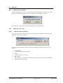
"New" menu item
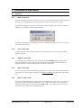
Select this menu item in order to create a new bore log. You will thus delete all existing entries for
bore logs. You should therefore ensure that you have properly saved any previous logs.
The following dialogue box opens for selecting the required standard. If the check box is deactivated bore log visualisation is based on DIN 4022for .
An empty standard page corresponding to the chosen standard will appear on the screen. You can
now enter a new bore log.
5.1.2
"Load" menu item
You can load a file with strata data, which was created and saved at a previous sitting, and then
edit the strata data.
5.1.3
"Add file" menu item
You can load a file created at a previous sitting with the GGU-BORELOG program into a currently displayed bore log. The data from the selected file will be added to the current data. It is
therefore possible to create one data set from several previous data sets.
5.1.4
"Save" menu item
You can save data entered or edited during program use to a file, in order to have them available at
a later date, or to archive them. The data is saved without prompting with the name of the current
file.
5.1.5
"Save as" menu item
You can save data entered during program use to an existing file or to a new file, i.e. using a new
file name. For reasons of clarity, it makes sense to use ".sch" as file suffix, as this is the suffix
used in the file requester box for the menu item "File/Load". If you choose not to enter an extension when saving, ".sch" will be used automatically.
GGU-BORELOG User Manual
Page 6 of 36
March 2010
5.1.6
"Import GGU-STRATIG file" menu item
This menu item allows loading of files created with the GGU-STRATIG (graphical presentation
of bore profiles). These data can then be equipped with additional information typical for bore
logs. The default suffix for the GGU-STRATIG progam is ".bop". Before the GGU-STRATIG
file can be imported into GGU-BORELOG, you must define the import format.
In order to achieve maximum import security, it is best to create the GGU-STRATIG file using
the SEP 2 abbreviations. Select the upper switch "Interpret SEP abbreviations from GGUSTRATIG".
5.1.7
"Add GGU-STRATIG file" menu item
This menu item allows adding of files (see also Section 5.1.3) created with GGU-STRATIG
(graphical presentation of bore profiles). Otherwise, the information for the menu item
"File/Import GGU-STRATIG file" is valid.
5.1.8
"Save GGU-STRATIG file" menu item
Once you have created a bore log, you can create a further file from this, which can then be read
and edited by GGU-STRATIG. As the bore log generally contains much more information (e.g.
information on the drilling process, geological information, etc.) than the graphical output of
GGU-STRATIG, it usually makes more sense to first create the log and then the GGUSTRATIG file, using this menu item. Output to GGU-STRATIG is:
GGU-BORELOG User Manual
Page 7 of 36
March 2010
5.1.9
"Printer preferences" menu item
You can edit printer preferences (e.g. swap between portrait and landscape) or change the printer
in accordance with WINDOWS conventions.
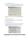
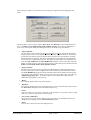
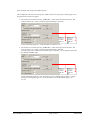
5.1.10
"Print all bore logs" menu item
All bore logs entered can be sent to the local printer using this menu item. A different printer may
also be selected by pressing "Printer prefs./change printer"
Specify the required number of copies in the dialogue box. The other group boxes show the currently used page format and information on the printable area for the selected printer. If the page
settings do not allow the page to be output completely on one sheet, the necessary adjustments can
be made by pressing "Adjust boundaries". The following dialogue box opens:
GGU-BORELOG User Manual
Page 8 of 36
March 2010
Click the "Refresh" button afterwards if these settings are manually adjusted. The new data is
then compared to the printer data and the result displayed. It is also possible to specify the left and
lower boundaries only and have the program determine the required sizes by pressing "Adapt
page height/page width to printer".
GGU-BORELOG User Manual
Page 9 of 36
March 2010
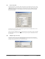
5.1.11
"Print individual bore logs" menu item
The individual pages of the bore log can be printed using this menu item.
Select the required pages and the number of copies in the upper group box. Below this the same
settings are available for page optimisation as where previously described for the menu item "File/Print all bore logs" (see Section 5.1.10).
Start the printing process by pressing "Print selected pages". It is possibly to quickly print the
bore log page currently displayed on the screen without making any selections beforehand by
pressing "Print current page".
5.1.12
"Exit" menu item
After a confirmation prompt, you can quit the program.
5.1.13
"1, 2, 3, 4" menu items
The "1, 2, 3, 4" menu items show the last four files worked on. By selecting one of these menu
items the listed file will be loaded. If you have saved files in any other folder than the program
folder, you can save yourself the occasionally onerous rummaging through various sub-folders.
GGU-BORELOG User Manual
Page 10 of 36
March 2010
5.2
Edit menu
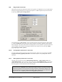
5.2.1
"Preferences" menu item
The following dialogue box opens for selecting the required standard. In an existing bore log this
allows easy movement between the various visualisations of the different standards.
If the check box is deactivated bore log visualisation is based on DIN 4022.
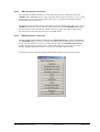
5.2.2
"Bore log" menu item
5.2.2.1
General processing options
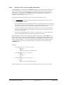
This menu item allows new bore log input or existing bore logs to be edited. The following dialogueue box will open, for example:
Two bore logs B1 and B2 are already present in this example. The following actions are now
possible:
• "To menu bar"
You return to the original menu bar.
• "New"
You will create a new bore log.
• "B 1", "B 2", ...
By clicking a box containing a borehole name (here: B 1 and B 2) the corresponding bore
logs opens and can be edited.
GGU-BORELOG User Manual
Page 11 of 36
March 2010
After clicking on "New" or on the button of an existing bore log the following dialogueue box
opens:
The descriptions of the two upper buttons "Base data" and "Horizons" can be found in Sections
5.2.2.2 - Fehler! Verweisquelle konnte nicht gefunden werden.. The following additional actions can be started in the subsequent dialogue boxes for the B1 bore log selected here:
• "Import SEP file"
The box allows a file created using the SchichtenErfassungsProgramm (Strata Recording
Program) SEP (Version 2) developed by LBEG (formerly NLfB) in Hannover, Germany to
be imported. The abbreviations used in the SEP 2 program were developed for recording
data from field investigations. The SEP 2 abbreviations are automatically interpreted and
converted to the corresponding long text. The highest possible degree of compatibility between the GGU-STRATIG and GGU-BORELOG programs can be achieved by using the
SEP 2 set of abbreviations. The SEP 2 abbreviations are described in more detail in Section
Fehler! Verweisquelle konnte nicht gefunden werden..
• "Export SEP file"
The abbreviation record can be exported in the LBEG Hannover SEP 2 program format.
The only requirement is that stratigraphic data was entered using the SEP 2 abbreviations.
The GGU-BORELOG program includes the SEP 2 abbreviations defined for the engineering geology field. Therefore, when exporting your bore log to a SEP 2 file, select the type
"Engineering geology (IG)". An input box opens for the header data required by the
LBEG SEP 2 program for every bore log.
• "Delete"
The currently displayed bore log will be deleted.
• "Duplicate"
The currently displayed bore log will be duplicated. You will automatically find yourself in
the "Base data" dialogueue box of the dublicated bore log.
• "Print"
Only the current bore log will be printed (B 1 in the example). It is possible to print a single
sheet only, if the bore log consists of several pages.
• "Save (GGU-STRATIG)"
The current bore log (B 1 in the example) can be exported as an individual borehole as a
".bop" file for importing into the GGU-STRATIG program.
• "Done"
You will arrive back at the previous dialogueue box.
GGU-BORELOG User Manual
Page 12 of 36
March 2010
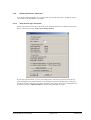
5.2.2.2
"Base data" button
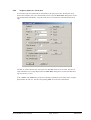
Using the "Base data" button in the editor box belonging to the "Edit/Bore log" menu item, the
specific base data for a new bore log can be entered or the data of an existing bore log be edited.
For y new bore log you will see the following dialogue box, for example:
The borehole data entered here are in turn entered into the form corresponding to the selected
standard. Activating the "Bore" and "Trench" radio buttons and the "+ absolute height" check
box facilitates the corresponding input on the form.
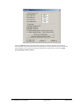
Some of the input boxes in the above dialogue box are hidden by default, because they are normally specified once for all bore logs or annexes. If the input rows are activated in the menu item
"Edit/Project, report, etc." (see Section 5.2.4), input can be made individually for each bore log,
as shown in the example dialogue box below.
Project no.:
Annex no.: 3.#
Page: #
The default entries for "Report:" and "Annex:" can be edited as required (e.g. to "Project no.:"
and "Page no."). In addition, it is possible to generate automatic numbering within the bore log by
entering "#" in the input rows after "Annex:" and "Annex no.". In the example above the annexes
are sequentially numbered in the format 3.1, 3.2, 3.3 etc., by entering "3.#" (also see Section 5.2.4,
menu item ‘Edit/Project, report, etc.’).
GGU-BORELOG User Manual
Page 13 of 36
March 2010
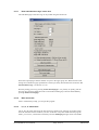
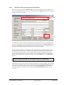
5.2.2.3
"Horizons" button: General data input information
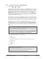
After selecting a bore log in the "Edit/Bore log" menu item's dialogue box, the ground structure
of the corresponding bore log can be entered or edited using the "Horizons" button. The following
dialogue box shows an example:
abbreviation
line
code
numbers
A stratum input is always possible via manual input of the description in the corresponding input
boxes. It is much quicker to use the abbreviations in the uppermost line, the abbreviation line. By
clicking the "Interpret" button after entering the abbreviations, the program automatically enters
the long texts associated with the abbreviations in the corresponding lines.
Two abbreviation systems are envisaged: the GGU abbreviations, as a relatively simple system
developed from practical use for recording strata, and the SEP 2 abbreviations from the 'Schichten-Erfassungs-Programm SEP' (Version 2) published by the LBEG Landesamt für Bergbau,
Energie und Geologie (formerly: Geological Survey of Lower Saxony NLfB). You can switch
between the two abbreviation systems by clicking on the "GGU abbrevs." or the "SEP abbrevs."
buttons.
Due to the greater flexibility, the SEP abbreviations are recommended.
At the bottom right you will see four boxes with code numbers. The code numbers control the fill
of the horizon presentation with soil type symbols according to German Standard DIN 4023. The
code numbers are only relevant if the bore logs entered in GGU-BORELOG are required for
subsequent graphical visualisation as soil columns in the GGU-STRATIG program (see Section 5.2.2.6).
GGU-BORELOG User Manual
Page 14 of 36
March 2010
There are a further nine buttons in the lower area of the "Horizons" dialogue box, used for the
following actions:
• "Previous"
You will return to the previous horizon. Alterations to the current horizon will be saved.
• "Next"
You will advance to the next horizon. Alterations to the current horizon will be saved.
• "Delete"
The horizon displayed in the dialogueue window will be deleted.
• "Paste"
An additional horizon can be pasted prior to the displayed horizon.
• "Remarks"
Clicking this box generates a dialogue box for entering remarks or similar on the borehole.
They appear on the DIN 4022 form in column 3 or in column 7 of the ISO 14688-1 form.
Some long texts interpreted from abbreviations, e.g. groundwater level information, are automatically entered in the corresponding columns for the selected standard during interpretation.
• "Sh. text"
The short text relevant for using the record for graphical visualisation in GGU-STRATIG
can be entered in this dialogue box.
• "Samples"
Enter the type, number and depth of samples in this dialogue box. These data can be found
in the DIN 4022 form in columns 4, 5 and 6 or on the ISO 14688-1 form in column 6. The
samples can also be entered and interpreted using the SEP 2 abbreviations (see explanation
in Section Fehler! Verweisquelle konnte nicht gefunden werden. "SEP abbreviations").
• "Cancel"
Horizon input will be stopped. Alterations to the displayed horizon will be rejected.
• "Done"
Horizon input is complete. Alterations to the displayed horizon will be accepted.
GGU-BORELOG User Manual
Page 15 of 36
March 2010
5.2.2.4
"Horizons" button: Input using GGU abbreviations
If "GGU abbrevs." are selected in the "Horizons" dialogue box, the abbreviations used by GGU
prior to the introduction of SEP abbreviations are entered in the abbreviation line. The GGU
abbreviations are contained in the "KURZ.txt" file and include all necessary parameters (long
text, short text, code number). The GGU abbreviations can be edited using the menu item
"Edit/GGU abbreviations" (see Section 5.2.12).
For horizon input using GGU abbreviations, the following agreements are valid:
• A maximum of 6 abbreviations will be interpreted, to be separated by comma or space.
• A "#" will not be interpreted.
• The first abbreviation will be interpreted as main soil type and used in the text. The second
abbreviation, if it begins with a capital letter, will also be interpreted as a main soil type. If
two main soil types are present, they will be automatically connected with a "+".
• The 3rd and 4th abbreviation, and the 2nd abbreviation for lower case, are interpreted as
accessory soil types. If no accessory soil types are present enter the hash sign "#" two or
three times as appropriate.
• The fifth and sixth abbreviations for further soil characteristics (e.g. colour) will be interpreted according to the default preferences and entered into the form.
When entering the GGU abbreviations the horizon depth is entered first in the "Depth" box, i.e.
the horizon base relative to the top of the stratigraphic log. Then enter the abbreviations for the
soil types and colours in the abbreviation line and click the "Interpret" command button or press
the key combination [Alt] + I. The program then interprets the abbreviations and generates the
corresponding long text, short text and code numbers in accordance with the contents of the
"KURZ.txt" file.
Examples:
• The abbreviations "U, T, fs-, ms+, ge" give:
Silt + clay
yellow
slightly fine-sandy, very medium-sandy
• The abbreviations "S, #, u, #, hbr" give:
Sand
light brown
silty
• The abbreviations "S, u+, t, fg-, gr" give:
Sand
grey
very silty, clayey, slightly fine-gravelly
After interpretation you can edit and extend the long and short texts according to your wishes.
GGU-BORELOG User Manual
Page 16 of 36
March 2010
5.2.2.5
"Horizons" button: Input using SEP abbreviations
SEP stands for SchichtenErfassungsProgramm.
The SEP program, Version 2 of which is implemented in GGU-BORELOG, was developed by
LBEG (Landesamt für Bergbau, Energie und Geologie, formerly: Niedersächsisches Landesamt
für Bodenforschung, NLfB) in Hannover and allows the acquisition of data collected in field investigations. This program includes a set of abbreviations that can also be selected for use in the
GGU-STRATIG program for entering strata using abbreviations. If you have the GGUSTRATIG program (graphical presentation of stratigraphic logs), as well as GGU-BORELOG,
you can achieve the highest possible compatibility between the data sets of both programs by
exclusively using the SEP 2 abbreviations.
For a detailed study of the SEP 2 abbreviations please see the SEP 2 manual, available from the
LBEG. After bore or sounding input, GGU-BORELOG allows saving in a SEP 2 compatible
format, if you have used the SEP 2 abbreviations. You can thus achieve a high degree of compatibility to other applications. Loading of files created with the SEP 2 program is also supported.
The abbreviations defined by LBEG for the "Engineering geology" subset are included in the
"SEPKURZ.TXT" file, which is included with the program. The existing SEP 2 abbreviations
can be viewed, printed and, if necessary, modified in the menu item "Edit/SEP abbreviations"
together with the long texts and short texts, and the code numbers for controlling soil column
hatching.
If files created using modified SEP 2 abbreviations are forwarded to third parties, compatibility with the receiver's programs cannot be guaranteed, because the modified abbreviations are not available and cannot therefore be interpreted.
If data forwarding is required, e.g. at the client’s request, it is better to work with the original SEP 2 file (for transfer to the SEP 2 program) or to send the modified "SEPKURZ.txt"
file with the data (for transfer to GGU-BORELOG and GGU-STRATIG).
A SEP 2 abbreviation line consists of seven input areas :
• Depth
• Stratigraphy (age)
• Petrography (main soil types + accessory soil types + characteristics if necessary)
• Genesis (origin)
• Colours
• Supplements
• Samples
These input areas are each separated by a " / ".
In the petrography field, the main and accessory soil types are separated by a " ; ".
Several abbreviations within a field are separated by commas " , ".
GGU-BORELOG User Manual
Page 17 of 36
March 2010
Depth / Stratigraphy / Petrography (main) ; Petrography (accessory) / Genesis /
Colours / Supplements / Samples
The SEP 2 program allows an abbreviation line length of 256 characters. GGU-BORELOG also
allows this line length. If the number of abbreviation characters goes above a value of 60, the
input window will scroll horizontally to the left. With the [Pos1] key you can return to the beginning of the line. With the [End] key you can move to the end of the abbreviation line.
Abbreviations for properties can be entered in any position in the petrography field, e.g. information on grain roundness for a fine gravel constituent or on lime content. The abbreviations and
corresponding long texts can be found under "Edit/SEP abbreviations" by pressing the dialogue
box button "Petrographic properties".
Quality information is noted by a number associated with the corresponding abbreviation. They
are allocated as follows: "1" = "very slight", "2" = "slight", "4" ="strong", "5" = "very strong". It
is not necessary to enter the "3" = "middle".
• Example:
The following horizon is to be entered:
Horizon base = 2,35 m
Medium sand, slightly fine-sandy, very silty, brown, soil group SU*,
stratigraphy, genesis and samples not present
The abbreviation line is:
2,35 / / mS ; fs2 , u4 / / bn / SaU2
After pressing the "Interpret" button all input will be converted to long texts.
If an input is not required in an area (e.g. stratigraphy), simply leave the "Stratigraphy"
area empty (see example above).
Unnecessary fields at the end of a line are simply left blank (in the above example: no samples, the line ends after the soil group abbreviation).
For colour input, two colours can also be combined. For example:
•
gero
==> yellowred (ge = yellow; ro = red)
•
dbn
==> dark brown (d = dark; bn = brown)
If an "=" is entered after the colour abbreviation, the long text will be supplemented with "ish".
For example:
•
ge=
==> yellowish
•
ro=
==> reddish
GGU-BORELOG User Manual
Page 18 of 36
March 2010
If an abbreviation from a different input area is to be used in any of the areas, the area designation
•
S:
for Stratigraphy
•
P:
for Petrography
•
G:
for Genesis
•
F:
for Colours
•
Z:
for Supplements
must be entered. For example:
• 2,35 / / mS ; fs2 , u4 , F:bn / / SaU2
The colour brown (bn) will thus be interpreted into the "Petrography" area.
Free text can be entered into any area. The free text must be entered in apostrophe's. For example:
• 2,35 / / 'Construction rubble', mS ; fs2 , u4 / bn / SaU2
The free text Construction rubble will thus be interpreted into the "Petrography" area.
If you would like to have the long text in brackets, simply enter these at the desired position in the
abbreviation line. For example:
• 2,35 / / 'Construction rubble', (mS) ; fs2 , u4 / bn / SaU2
Medium sand, in long text, will then be placed in brackets.
Using the Supplements field in the SEP 2 abbreviation line it is possible to record the soil group,
the consistencies or the drilling progress in the corresponding fields of the bore log form. The
allocations are defined by the column names in the "SEPKURZ.txt" file (also see menu item
"Edit/SEP abbreviations", dialogue box button "Supplements", Section 5.2.13). It is also possible to combine a number of abbreviations, e.g. "kos2-kos3" for consistencies "soft to firm".
In the supplements field abbreviations are also provided for describing groundwater conditions.
The depth information is entered in brackets following the abbreviation. Additional descriptions,
e.g. the date, are entered in single quotation marks and follow after the depth data and a space or
comma.
The brackets containing the depth data must immediately follow the groundwater abbreviation, without a space.
The decimal separator for depth input must be a point, not a comma.
Example:
• 2.35 / / 'Building waste', mS ; fs2 , u4 / bn / SaU2, bv3-bv4, gws(2.66,'30.08.01')
This means that in the DIN 4022 form, for example, the soil group in column "2h" is entered as "SU*", "medium - difficult to drill" is entered in column "2d" and "GW risen to
(2.66, 30.08.01)" in column "3".
GGU-BORELOG User Manual
Page 19 of 36
March 2010
Input of samples and their designations follows at the end of the abbreviation line. After the final
supplement input enter a " / " and begin with the depth from which the sample was taken.
It is important that the sample depth information is entered using a decimal point, not a
comma.
You can then enter the field designation in brackets. For the type of sample, the SEP abbreviations
are available once again, which you can view or supplement in "Edit / SEP abbreviations", button "Samples". The sample type (e.g. special sample) must also be placed in brackets and be separated from the sample designation by a comma. If a further sample has been taken from the same
horizon, separate the entries with a " ; " and enter the depth, number and type in the same sequence.
• For example the entry
....... / 1.2 (Gl 1) , (bp1) ; 1.4 (Gl 2) , (so)
means very poor quality bore sample (= bp1) at a depth of 1.2 m in glass 1 and a special
sample (= so) at a depth of 1.4 m in glass 2
The sample base level is entered in the format shown above. If the top and bottom of the sample
need to be displayed, the appropriate check box must first be activated under "Edit/SEP abbreviations", dialogue box button "Preferences". Depth input then follows the example below:
• ......./ 1.0-1.2 (Gl 1), (kp)
This allows both depths to be used in the form.
The SEP 2 program is much more consequential than the DIN 4022. The genetic expressions
topsoil, boulder clay, fill, etc., e.g., are thrown into one pot with purely petrographic expressions
(e.g. sand, gravel, etc.) in DIN 4022. If you would like to enter these genetic expressions in the
first position in the long text line, using GGU-BORELOG (e.g. to 1.2 m fill, sand, silty), you
must enter the following abbreviation line:
• 1,2 / / G:y , S , u
Where "G:" stands for the genetic abbreviation subset and the "y" is the SEP 2 abbreviation for
fill from this subset. In principle, it also imaginable to enter the "y" abbreviation, together with the
long text "fill" into the petrography subset. This procedure may be pragmatic, as you can do without input of the "G:", you will, however, lose compatibility to the SEP 2 program. The functionality of the GGU-BORELOG program will not be restricted in any way. You can also create a
completely different set of abbreviations with completely different long texts.
GGU-BORELOG User Manual
Page 20 of 36
March 2010
5.2.2.6
Data exchange with GGU-STRATIG
If you not only work with the GGU-BORELOG program, but also need to use the data entered in
the GGU-STRATIG program for graphical visualisation of the stratigraphic logs, please note the
following points:
• Always use the SEP 2 abbreviations, because they allow you to transfer considerably more
information in an abbreviated format.
• In the supplements field, always enter the soil group, consistency and groundwater as
abbreviations.
• Always enter the samples using the abbreviation line. Use the description of the sample type, e.g. so = special sample. The symbol for special sample (filled box) is then automatically displayed in GGU-STRATIG.
• When interpreting the abbreviations a short text is created automatically and can be used to
achieve a narrow stratigraphic log when the data are transferred to GGU-STRATIG.
• Each abbreviation in the petrography field is allocated a code number. These code numbers
control the soil type fill symbols used in the stratigraphic log visualisation to DIN 4023. A
maximum of four code numbers can be allocated for horizon input (see Section 5.2.2.3).
The four data boxes (code boxes) are filled in from left to right when interpreting a SEP 2
abbreviation line. The first two code boxes facilitate a complete fill of the allocated soil
signatures for visualisation in GGU-STRATIG; they are therefore reserved for main soil
types and soil types with large proportions of other constituents. The last two code boxes
only fill half of the log with the allocated soil signatures; they should be reserved for medium to small proportions of soil types.
In order to prevent the code number for the following accessory soil type being written in
the second code box when there is only one main soil type, a place holder (#) is entered in
the abbreviation line, e.g.:
2.35 / / mS ; # , fs2 , u4 / / bn / SaU2.
The place holder ‘#’ does not influence visualisation of the bore log GGU-BORELOG.
Data transfer to GGU-STRATIG can also be carried out if abbreviations are not used, i.e. the
horizons are entered by hand in the text rows. A correct file is also created in this case, but it then
requires post-processing in GGU-STRATIG.
The individual bore log can be saved as a GGU-STRATIG file using the button "Save (GGUSTRATIG)" in the general dialogue box of the "Edit/Bore log" menu item (see Section 5.2.2.1).
If all bore logs need to be transferred to GGU-STRATIG use the menu item "File/Save GGUSTRATIG file" (see Section 5.1.8).
GGU-BORELOG User Manual
Page 21 of 36
March 2010
5.2.3
"Heading and header" menu item
The default format for the DIN 4022 form includes a two-line header. The two form title lines can
be modified, depending on whether a bore log is to be created to DIN 4022-1, DIN 4022-2 or
DIN 4022-3. The height of the form header can be increased by a maximum of 5 mm in the dialogue box’s lower group box.
For a bore log to ISO 14688-1 the information on the borehole and the project given in the dialogue box are displayed on the form. This menu item also allows modification to the input box designations. Data input is made in the menu item "Edit/Additional data" (see Section 5.2.6).
If the various bore logs are regularly used, a number of different templates can be created using
the appropriate titles and designations and saved to different ".alg" files in "Edit/Save gaphics
preferences" (see Section 5.2.11).
GGU-BORELOG User Manual
Page 22 of 36
March 2010
5.2.4
" Project, report, etc " menu item
If several bore logs are loaded and you would like to edit the project name, the date, the report
and/or annex number, then you would normally need to open the "Base data" dialogue box for all
logs and edit them individually. Using this menu item you can have the same data entered in all
logs.
The data are used in all bore logs if the respective "For all" check box is activated. The lines of
input ticked here are no longer displayed in the ‘Base data’ dialogue box for the individual bore
logs (see Section 5.2.2.2).
In the "Annex" and "Annex no." group boxes automatic numbering can be achieved by using the
place holders "#" and "%". See the corresponding "Info" boxes for more information.
GGU-BORELOG User Manual
Page 23 of 36
March 2010
Some examples will clarify the available options:
The example file contains two bore logs, B 1 und B 2. Each bore log consists of three pages, meaning the file has a total of six pages.
1. The Annex box contains text only: "Annex no.:", which is the same for all annexes. The
input for Annex no. is "3.#", continuous page numbering is activated.
Annex numbering begins at 3.1 and continues in sequence to 3.6.
2. The Annex box contains text only: "Annex no.:", which is the same for all annexes. The
input for Annex no. is "3.#", continuous page numbering is activated.
A header page will be added in front of bore logs B 1 and B 2; a "1" is therefore entered for
the number of header pages.
Annex numbering begins at 3.2 for bore log B 1, the B 1 header page is Annex 3.1. Numbering for bore log B 2 begins at 3.6 and continues to 3.8, the B 2 header page is Annex 3.5.
GGU-BORELOG User Manual
Page 24 of 36
March 2010
3. Numbering has been entered in Annex, to be increased with each borehole only. The current page number and the total number of pages in Annex 3 are entered in Annex no. Remember that a header page is added in front of each borehole.
The B 1 bore log is annex number 3.1, that of B 2 is 3.2. With a header page per borehole
page numbering for borehole B 1 starts on page 2 and on page 6 for borehole B 2. A total
page number of 8 then results for Annex 3, including the header pages.
5.2.5
"Company" menu item
This menu item is active for visualisation to DIN 4022. A dialogue box with five text lines opens.
The lines are for entering your company address data. The texts are displayed at the top left of the
DIN 4022 form. Once entered, the company data can be saved in the "GGU-BORELOG.alg" file
in the program folder (see Section 5.2.11). The company data are then automatically available for
new bore logs whenever the program is started.
5.2.6
"Additional data" menu item
This menu item is active for visualisation to ISO 14688-1. A dialogue box opens for entering the
data required by the ISO standard. The input box designations can be adapted to your personal
needs in the menu item "Edit/Heading and header" (see Section 5.2.3). The data entered here
can be saved in the "GGU-BORELOG.alg" file in the program folder (see Section 5.2.11). The
data are then automatically available for new bore logs whenever the program is started
GGU-BORELOG User Manual
Page 25 of 36
March 2010
5.2.7
"For all" menu item
Using this menu item it is possible to make certain entries for all existing bore logs at once. These
include information on the project and report, normally entered for all bore logs via the menu item
"Edit/Project, report, etc." (see Section 5.2.4). The input boxes are only available in the "For
all" menu item's dialogue box if the "For all" check boxes have been deactivated. The dialogue
box then looks like this:
In order for the texts to be used in all existing bore logs the respective "For all" check box must
be pressed for the appropriate line of text.
The texts entered in "For all" are then not used automatically in subsequently created or appended
bore logs. If these entries need to be used for new bore logs the respective "For all" buttons must
be clicked again.
5.2.8
"Swap bore logs" menu item
The sequence of the bore logs can be swapped using this menu item. This can be useful if log
collections have been imported from GGU-STRATIG, but the borehole series was entered corresponding to the required profile and not to the borehole names.
GGU-BORELOG User Manual
Page 26 of 36
March 2010
5.2.9
"Page format" menu item
This menu item allows the dimensions of the bore log form to be adapted to suit your requirements
and/or the maximum dimensions accepted by the printer. A different printer may also be selected
by pressing "Printer prefs./change printer".
In the dialogue box, "Does not fit!" can be seen following the value for the printer's right boundary. Click the "Refresh" button afterwards if these settings are manually adjusted. The new data is
then compared to the printer data and the result displayed. It is also possible to specify the left and
lower boundaries only and have the program determine the required sizes by pressing "Adapt
page height/page width to printer".
5.2.10
"Load graphics preferences" menu item
You can reload a graphics preferences file into the program, which was saved using the "Graphics preferences/Save graphics preferences" menu item. Only the corresponding data will be
refreshed.
5.2.11
"Save graphics preferences" menu item
The data entered in the menu items "Edit/Heading and header", "Edit/Company data" and
"Edit/Additional data" can be saved to a file. If you select "GGU-BORELOG.alg" as file name,
and save the file on the same level as the program, the data will be automatically loaded the next
time the program is started and need not be entered again.
If you do not go to "File/New" upon starting the program, but open a previously saved file
instead, the preferences used at the time of saving are shown. If subsequent changes in the
general preferences are to be used for existing files, these preferences must be imported using the menu item "Graphics preferences/Load graphics preferences".
GGU-BORELOG User Manual
Page 27 of 36
March 2010
5.2.12
"GGU abreviations" menu item
An explanation of modus operandi of the GGU abbreviations can be found in the menu item
"Edit/Bore log" ("Horizons" button: Input using GGU abbreviations) (see Section 5.2.2.4). Using
this menu item you can edit the GGU abbreviations, the corresponding code numbers and the
corresponding long and short texts.
The dialogueue box also allows saving of the abbreviation file (default suffix ".txt"). If you select
"KURZ.txt" as file name, and save the file on the same level as the GGU-BORELOG program,
the abbreviations will be automatically loaded at the next program start. Different abbreviation
files can also be created and used as required via "Load" button.
5.2.13
"SEP abreviations" menu item
The SEP 2 abbreviations defined by LBEG for the "Engineering geology" subset are included in
the "SEPKURZ.TXT" file, which is included with the program. The existing SEP 2 abbreviations
can be viewed, printed and, if necessary, modified in the menu item "Edit/SEP abbreviations"
together with the long texts and short texts, and the code numbers for controlling soil column
hatching. Modified SEP 2 abbreviations can also be saved under a different name.
A dialogue box opens containing the SEP 2 abbreviations divided into the respective fields.
GGU-BORELOG User Manual
Page 28 of 36
March 2010
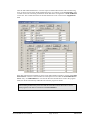
Click the individual field buttons to view the respective SEP 2 abbreviations and associated long
texts, as shown in some of the displayed dialogue boxes. For example, in the "Petrography" field
a column with codes controlling visualisation of the DIN 4023 soil signatures in GGU-STRATIG
can be seen. The column allocations for the DIN 4022 form can be viewed in the "Supplements"
field.
If the SEP 2 file has been modified, it can be saved under a different name by pressing "Save SEP
abbreviations". This file is then available for subsequent sessions under the "Load SEP abbreviations" entry. If "SEPKURZ.TXT" is used as the file name and the file is saved in the program
folder, the file be automatically loaded the next time the program is started.
When making modifications please note that the same abbreviations file must be used in
both programs if the data are transferred to GGU-STRATIG.
GGU-BORELOG User Manual
Page 29 of 36
March 2010
5.3
5.3.1
Graphics preferences menu
"Refresh and zoom" menu item
The program works on the principle of What you see is what you get. This means that the screen
presentation represents, overall, what you will see on your printer. In the last consequence, this
would mean that the screen presentation would have to be refreshed after every alteration you
make. For reasons of efficiency and as this can take several seconds for complex screen contents,
the screen is not refreshed after every alteration.
If, e.g., after using the zoom function (see below), only part of the image is visible, you can
achieve a complete view using this menu item.
A zoom factor between 0.4 and 8.0 can be entered in the input box. By then clicking on "Use" to
exit the box the current factor is accepted. By clicking on the "0.4", "0.6", etc. buttons, the selected factor is used directly and the dialogueue box closed.
It is much simpler, however, to get a complete overview using [Esc]. Pressing [Esc] allows a complete screen presentation using the zoom factor specified in this menu item. The [F2] key allows
screen refreshing without altering the coordinates and zoom factor.
5.3.2
"Zoom info" menu item
By clicking two diametrically opposed points you can enlarge a section of the screen in order to
view details better. An information box provides information on activating the zoom function and
on available options.
5.3.3
"Font selection" menu item
With this menu item you can switch to a different true-type font. All available true-type fonts are
displayed in the dialogueue box.
GGU-BORELOG User Manual
Page 30 of 36
March 2010
5.3.4
"Header toolbar" menu item
Using this menu item you can add free text to the bore logs and add lines, circles, polygons and
images (e.g. files in formats BMP, JPG, PSP, TIF, etc.).
All drawing objects created using Mini-CAD are used on every page of the bore log.
This menu item is therefore only of use for special labelling, e.g. for use in the company
logo.
A pop-up menu opens; the icons and functions used are described in more detail in the "MiniCAD" manual provided.
5.3.5
"Toolbar preferences" menu item
After starting the program a horizontal toolbar for menu items appears below the program menu
bar. If you would rather work with a popup window with several columns, you can specify your
preferences using this menu item. The smarticons can also be switched off.
At the bottom of the program window you find a status bar with further information. You can also
activate or switch off the status bar here. The preferences will be saved in the "GGUBORELOG.alg" file (see menu item "Graphics preferences/Save graphics preferences") and
will be active at the next time the program is started.
By clicking on the tools (smarticons) for the menu items you can directly reach most of the
program functions. The meaning of the smarticons appears as a text box if you hover with the
mouse pointer over the tools. Some of the tool functions cannot be activated from the normal
menu items.
"Zoom out"
If you have previously zoomed in, this tool returns to a full screen display.
"Zoom (-)"/"Zoom (+)"
With the zoom functions you can zoom in or out of parts of the image, by clicking the left mouse
button.
"Copy/print area"
Use this tool to copy only parts of the graphics in order to paste them, e.g. to a report. You will see
information on this function and can then mark an area, which is copied to the clipboard or can be
saved in a file. Alternatively you can send the marked area directly to your printer (see "Tips",
Section 6.3).
"Previous page"/"Next page"
If there are several pages of bore logs, navigate through the pages by clicking these icons. The
[F11] and [F12] function keys can also be used for navigation. The current page is displayed in
the status bar.
GGU-BORELOG User Manual
Page 31 of 36
March 2010
5.4
5.4.1
? menu
"Copyright" menu item
You will see a copyright message and information on the program version number.
The "System" button shows information on your computer configuration and the folders used by
GGU-BORELOG.
5.4.2
"Maxima" menu item
You will see information on the default program maxima.
5.4.3
"Help" menu item
The GGU-BORELOG online-help is opened using an installed browser (e.g. MS Internet Explorer). The help function can also be accessed using the [F1] function key.
5.4.4
"Mini-Help" menu item
Descriptions of the use of the function keys and accessing dialogue boxes are displayed in an info
box.
5.4.5
"GGU on the web" menu item
Using this menu item you can access the GGU Software website: www.ggu-software.com.
Keep in touch with new program versions and the regular download offers.
If you would like to be automatically notified about program innovations, please register for the
Newsletter in our Knowledge Base. Go to the following website: http://kbase.civilserve.com.
5.4.6
"GGU support" menu item
This menu item takes to the GGU-Software Support area at www.ggu-software.com.
5.4.7
"What's new?" menu item
You will see information on program improvements in comparison to older versions.
5.4.8
"Language preferences" menu item
This menu item allows you to switch the menus and the graphics from German to English and vice
versa. To work in German, deactivate the two check boxes "translate dialogueues, menus" und
"translate graphics". You should then select the German abbreviation file from the drop-down
menu: "SEP-Kuerzel. (deutsch)".
Alternatively, you can work bilingually, e.g. with German dialogueue boxes but with graphic
output in English. The program always starts with the language setting applicable when it was last
ended.
GGU-BORELOG User Manual
Page 32 of 36
March 2010
6 Tips
6.1
Keyboard and mouse
You can scroll the screen with the keyboard using the cursor keys and the [Page up] and [Page
down] keys. By clicking and pulling with the mouse, with [Ctrl] pressed, you activate the zoom
function, i.e. the selected section will fill the screen. Furthermore you can use the mouse wheel to
zoom in /out or scrolling the screen presentation. The folling mouse wheel functions are available:
• Mouse wheel up
= move screen image up
• Mouse wheel down
= move screen image down
• [Ctrl] + mouse wheel up
= enlarge screen image (zoom in)
• [Ctrl] + mouse wheel down
= shrink screen image (zoom out)
• [Shift] + mouse wheel up
= move screen image right
• [Shift] + mouse wheel down
= move screen image left
If you click the right mouse button anywhere on the screen a context menu containing the principal menu items opens.
By double-clicking the left mouse button on output sheet or Mini-CAD objects, the editor for the
selected object immediately opens, allowing it to be edited.
6.2
Function keys
Some of the function keys are assigned program functions. The allocations are noted after the
corresponding menu items. The individual function key allocations are:
• [Esc] refreshes the screen contents and sets the screen back to the given page format (A4).
This is useful if, for example, you have used the zoom function to display parts of the
screen and would like to quickly return to a complete overview.
• [F1] opens the online-help.
• [F2] refreshes the screen without altering the current magnification.
• [F11] navigates forwards through the bore logs.
• [F12] navigates backwards through the bore logs. The current page is displayed in the status bar.
GGU-BORELOG User Manual
Page 33 of 36
March 2010
6.3
"Copy/print area" icon
A dialogueue box opens when the "Copy/print area" icon
in the menu toolbar is clicked,
describing the options available for this function. For example, using this icon it is possible to
either copy areas of the screen graphics and paste them into the report, or send them directly to a
printer.
In the dialogueue box, first select where the copied area should be transferred to: "Clipboard",
"File" or "Printer". The cursor is displayed as a cross after leaving the dialogueue box and, keeping the left mouse button pressed, the required area may be enclosed. If the marked area does not
suit your requirements, abort the subsequent boxes and restart the function by clicking the icon
again.
If "Clipboard" was selected, move to the MS Word document (for example) after marking the
area and paste the copied graphics using "Edit/Paste".
If "File" was selected, the following dialogueue box opens once the area has been defined:
The default location of the file is the folder from which the program is started and, if several files
are created, the file is given the file name "Image0.emf" with sequential numbering. If the
"Rename" button in the dialogueue box is clicked, a file selector box opens and the copied area
can be saved under a different name in an user-defined folder. Saving can be aborted by pressing
the "Delete" button.
If the "Printer" button was pressed in the first dialogueue box, a dialogueue box for defining the
printer settings opens after marking the area. Following this, a dialogueue box for defining the
image output settings opens. After confirming the settings the defined area is output to the selected
printer.
GGU-BORELOG User Manual
Page 34 of 36
March 2010
7 Index
A
Annex number, generate automatically
for all bore logs ............................................ 23
Annex number. enter the same for all
bore logs....................................................... 23
Annex numbers, enter for individual bore log .. 13
B
Base data, enter for individual bore log............ 13
Base data. enter the same for all bore logs ....... 23
Bore log, delete/duplicate ................................. 12
Bore log, enter/edit ........................................... 11
Bore log, navigate forwards/backwards............ 31
Bore log, print all pages...................................... 8
Bore log, print single page................................ 10
Bore logs, swap sequence ................................. 26
Boundaries, identify automatically..................... 8
GGU-STRATIG, conditions for
data exchange............................................... 21
Graphics, add via Mini-CAD............................ 31
Groundwater, interpret using SEP 2
abbreviations ................................................ 19
H
Horizon input, general ...................................... 14
Horizon input, using SEP 2 abbreviations ........ 17
Horizon, define/delete ...................................... 15
I
Installation .......................................................... 4
ISO 14688-1, use for visualisation ............... 6, 11
K
Knowledge Base, access................................... 32
C
L
Code numbers, enter for soil type symbols
to DIN 4023 ........................................... 14, 21
CodeMeter stick.................................................. 4
Company data, enter......................................... 25
Company logo, add via Mini-CAD .................. 31
Consistencies, interpret using SEP 2
abbreviations ................................................ 19
Context menu, open.......................................... 33
Copy/print area ........................................... 31, 34
Language preferences ................................... 4, 32
Licence protection .............................................. 4
D
Page format, determine automatically .......... 9, 27
Print, all pages .................................................... 8
Print, current bore log....................................... 12
Print, section ..................................................... 34
Print, single page .............................................. 10
Printer preferences........................................ 8, 27
Printer, preferences............................................. 8
Program, load/save preferences ........................ 27
Program, show default maximum values.......... 32
Program, show improvements .......................... 32
Program, show information .............................. 32
Project name. enter the same for all bore logs .. 23
Delete, bore log ................................................ 12
Delete, horizon ................................................. 15
DIN 4022, use for visualisation .................... 6, 11
DIN 4023, enter code numbers for
soil type symbols.................................... 14, 21
Drilling progress, interpret using SEP 2
abbreviations ................................................ 19
DXF file, import ................................................. 4
F
File, load/save..................................................... 6
Font selection ................................................... 30
Form, edit title .................................................. 22
Free text, interpret using SEP 2 abbreviations.. 19
Function keys ................................................... 33
M
Mini-CAD, use ................................................. 31
Mouse wheel functions ..................................... 33
P
Q
Quality information, interpret using SEP 2
abbreviations ................................................ 18
R
G
GGU abbreviations, edit ................................... 28
GGU abbreviations, information on use .......... 16
GGU-STRATIG file, export all bore logs .......... 7
GGU-STRATIG file, export individual
bore log ........................................................ 12
GGU-BORELOG User Manual
Remarks, enter manually .................................. 15
Report number, enter for individual bore log ... 13
Report number. enter the same for all
bore logs....................................................... 23
Page 35 of 36
March 2010
S
Samples, enter manually................................... 15
Samples, interpret using SEP 2 abbreviations .. 20
Scroll the screen ............................................... 33
SEP 2 abbreviations, edit.................................. 28
SEP 2 abbreviations, explanation of
input areas .................................................... 17
SEP 2 file, import/export .................................. 12
Short text, enter manually................................. 15
Smarticons, for menu items .............................. 31
Soil colours, interpret using SEP 2
abbreviations ................................................ 18
Soil group, interpret using SEP 2
abbreviations ................................................ 19
Soil type symbols, enter for
GGU-STRATIG export................................ 14
Soil type, interpret using SEP 2 abbreviations . 18
GGU-BORELOG User Manual
Status bar main program, activate..................... 31
System, show information ................................ 32
T
Toolbar, for menu items ................................... 31
Translation........................................................ 32
True-type font................................................... 30
W
What you see is what you get ........................... 30
Z
Zoom factor, define for full-screen display ...... 30
Zoom function, activate........................ 30, 31, 33
Page 36 of 36
March 2010