1
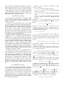
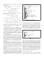
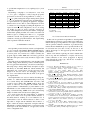
Smart Behavioral Netlist Simulation for SEU
Protection Verification
Simon Schulz, Giovanni Beltrame, David Merodio-Codinachs
Abstract— This paper presents a novel approach to verify
Single-Event-Upset (SEU) protection based on smart behavioral
simulation. Our analysis does not require a testbench and can
perform full, exhaustive coverage within less than an hour for
typical designs.
Index Terms— Triplication verification, SEU Analysis, Behavioral simulation, netlist conversion, Graph Representation,
I. I NTRODUCTION
Hardening circuits against radiation effects that occur in
space is a complex task. Without being protected by the earth’s
magnetic field, integrated circuits are exposed to ionizing
radiation, which can disrupt the circuits’ behavior.
This paper focuses on the so called Single-Event-Upset
(SEU) effects, or soft errors, usually caused by the transit
of a single ionizing particle through the chip. This particle
can upset storage elements and change their value from zero
to one or vice versa by modifying the charge at a storage
node [1]. Protection against this effect can be done in several
ways, and in particular this work concentrates on the protection
based on triple modular redundancy (TMR), consisting in the
triplication of every storage element combined with majority
voting logic [2].
This protection can be either inserted during high level
design [3] or at a later stage by automatic netlist modification.
Typically, after a new ASIC is produced for the space market,
it undergoes a strict test campaign, including costly and time
consuming radiation tests using particle accelerators. When a
problem arises during a radiation test campaign, it is already
too late; the first prototype ASICs have been manufactured and
the whole fabrication process needs to be rerun after fixing the
netlist. It is desireable to detect any problems before fabrication, therefore several software [4]–[7] and hardware-based [8]
tools for fault injection and verification were proposed in the
past. However, such tools either do not provide full coverage
or require extremely long simulation and/or execution times.
This paper presents a novel way to analyze the SEU
sensitivity of a given netlist by taking a gate-level netlist
as input and executing a smart behavioral simulation, and
verifying the correctness of the implemented countermeasures
against SEUs. To perform a fast analysis, we use a divide et
impera approach, transforming the input netlist into a directed
graph representation and analyzing smaller subgraphs. Results
show that verifying TMR on a 40k gates netlist is possible
within around half a hour on a standard PC. Another advantage
The authors are with the European Space Agency, ESTEC, 2200 AG
Noordwijk, The Netherlands (phone: +31 71 565 8357, fax: +31 71 565 6791,
e-mail: [email protected]).
over other traditional simulation/verification methods is that
our approach does not rely on a testbench, allowing a full
coverage test.
This paper is organized as follows: previous works on the
subject are introduced in Section II; Section III present the
base idea of the proposed algorithms; Section IV details the
algorithm together with necessary definitions, its implementation and its complexity; experimental results are shown in
Section V, and Section VI draws some concluding remarks.
II. P REVIOUS WORK
In the past, several different approaches have been proposed
for design verification against soft errors. These approaches
can be divided in two kinds: fault injection simulation and
formal verification.
Fault injection simulators run a given testbench on the design under test (DUT), flipping either randomly or specifically
targeted bits. The outputs of the DUT are then compared with
a golden model running the same testbench, and discrepancies
are reported. Fault injection simulators come in two different
flavors: on the one side there are software-based simulators
like MEFISTO-L [5] or SST [6] (which is based on Modelsim), that allow full observability and control of the simulated
netlist. These tools are marred by extremely slow low-level
simulation, requiring hours or days of simulation, without any
guarantee of full coverage. On the other hand some tools use
special hardware to speed up the simulation cycle, such as FTUnshades [8], which uses partial reconfiguration of an FPGA
to introduce single bit-flips (simulating SEUs) in a fast manner
without requiring modifications of the DUT. Although this
provides a consistent speedup compared to the software based
approach, it is still infeasible to run full verification of a given
design, which requires the injection of bit flips in all possible
Flip-Flops (FFs) at any possible time during the simulation.
In addition, the results of these approaches strongly depend
on the testbench used.
Formal verification against soft-errors was introduced
by [9]: the idea is to merge a formal model of the DUT with
a soft error model, proving a given set of properties on the
merged model. This requires a formal model of the DUT and
a complete and exhaustive set of formally defined properties
to be proven. In other words, the main issue of this formal
approach is that the coverage is as good as the definition of
such properties.
This work tries to overcome these limitations and provide
full SEU protection verification of a TMR-based DUT with
reasonable simulation time. The idea presented in this paper
can be classified as a fault-injection simulation, but follows a
different approach with respect to previous work: instead of
trying to simulate the whole circuit at once and doing a timing
accurate simulation we focus on the behavioral simulation
of small submodules, extracted by automatic analysis of the
DUT internal structure, with the specific goal of detecting any
FF/voter pairs that are susceptible to SEUs.
III. P ROPOSED A PPROACH
The starting point of our analysis is a radiation hardened
circuit, protected by triplication and voting (TMR [2]). The
objective of this analysis is finding any FFs that are not
adequately protected.
Starting from a given design with n FFs, a naive testing
approach for SEU-susceptible FFs would require testing all 2n
possible configurations, for all of the m time instants of a given
testbench. This would lead to an impractically long simulation
time as typical as systems consist of several thousand FFs.
Our approach uses the properties of the DUT in order to
split the whole system into smaller submodules. Those small
submodules can be analyzed independently, allowing a full test
to be carried out in a reasonable timeframe.
The DUT is initially converted into a directed graph representation, based on a post-synthesis gate-level netlist (e.g.
an EDIF file or a verilog netlist). This graph representation
consists of nodes (modeling logic gates) and edges describing
wires or interconnections between the gates. Using this representation, each FF i in the DUT is selected, and the subgraph
of FFs connected to i’s input is calculated. Then, all valid
start configurations (see Definition 6) for the FFs belonging to
this subgraph are calculated, simulating all possible injections
on the generated subgraph. For every injection, the result is
compared to fault-free simulation: if the results differ, the FF
i is marked as susceptible to SEUs.
We implemented a prototype of the algorithm relying on
some assumptions: the whole circuit is driven by only one
clock and there are no loops inside logic without a storage
element being involved. Furthermore, it is assumed that there
are no signal conflicts inside the netlist (i.e., two-valued logic)
and that there are no timing violations. Finally, we assume
that all FFs have one data input, one clock source, and all
the triplets have separate reset and set lines. For the sake of
simplicity, Single Event Effects (SEEs) on the reset and set
lines are not considered, but they could be analyzed in a similar
way.
IV. M ATHEMATICAL MODEL
To convert the netlist describing the circuit into a graph, we
need to introduce a special directed graph structure. The nodes
of this graph have indexed inputs and are associated with a
logic function and a value, as outlined in the following. We
assume without loss of generality that every gate has just one
output. Gates that have n 6= 1 outputs are converted into n
nodes having the same inputs, each representing one output.
Taking this into account the netlist can be easily converted
into a directed graph structure
Definition 1: A circuit graph G is defined as a tuple
{V, E, S, F }, where:
• V is a set of nodes (representing logic gates)
• E ⊆ V × V × N0 is a set of edges (representing
interconnection wires)
• S ⊆ V × {0, 1} is a set of values (representing the node
values)
• F ⊆ V × T is the set of logic functions associated with
each node, where T is the set of computable boolean
functions
Every node v ∈ V has 1 output and num inputs(v) ⊆ N0
inputs. The set of valid input indices for a node v ∈ V is
given by
Nv = {1, ..., num inputs(v)}
An edge e = (x, y, i) ∈ E with x, y ∈ V and i ∈ Ny
represents a connection from node x to the input i of node y.
Assuming that the input circuit is free of driving conflicts, the
circuit graph fullfills the property:
∀v, w, x ∈ V, ∀i ∈ Nv :
v 6= w ∧ (w, x, i) ∈ E =⇒ (v, x, i) 6∈ E
which means that any given input of a node is connected
to a single node output. We also assume that there are no
unconnected inputs in the circuit, which translates to the
property:
∀x ∈ V, ∀i ∈ Nx , ∃w ∈ V : (w, x, i) ∈ E
(1)
To describe the algorithm, we need to define predicates that
represent node properties.
Definition 2: The set of direct predecessors of node x, i.e.
the set of nodes with a direct connection from their output to
one of x inputs is defined as:
pre(x) = {w | ∃i ∈ Nx : (w, x, i) ∈ E}
Definition 3: Let us define the predicate is f f for a given
node x ∈ V , which determines if x represents a FF:
true if x ∈ V is a FF or in-/output node
is f f (x) =
f alse else
For the sake of simplicity, top-level in-/outputs are considered
as FFs with no inputs. The set of nodes that represent FFs is:
VF F = {x | ∀x ∈ V, is f f (x)}
Definition 4: We define the set of nodes which are directly
and indirectly connected to the inputs of a given node x ∈ V as
the smallest set pre f f s(x) for which the following properties
hold ∀w ∈ pre(x):
is f f (w) =⇒ w ∈ pre f f s(x)
¬is f f (w) ∧ v ∈ pre f f s(w) =⇒
v ∈ pre f f s(x)
Having defined the FFs as just having one input (see section
III) we can define the driving node for a given FF as
Definition 5: A driver for FF x ∈ VF F is defined as:
driver(x) = {y | (y, x, 1) ∈ E}
Finally, we need the operators to compute the values associated
with each node:
Definition 6: The value of a node x ∈ V is given by the
eval operator, defined as:
evalF F (x) if x ∈ VF F
eval(x) =
evalL (x)
else
where evalF F returns the value stored in FF x:
input : a node x ∈ V
1
2
3
4
5
6
7
evalF F (x) = {a | (x, a) ∈ S}
8
and evalL computes the value of logic (i.e., non FF) nodes,
which depends on the node input values:
10
9
11
evalL (x) ={f (eval(y1 ), ..., eval(yn ))
12
| (x, f ) ∈ F, yi ∈ pre(x)}
13
14
We also define the configuration of a set of FFs xi ∈ VF F as
conf ig(x1 , ..., xn ) = (eval(x1 ), ..., eval(xn ))
15
16
A configuration conf ig(x1 , ..., xn ) is defined as valid when
∀x1 , ..., xn ∈ VF F , ∀i ∈ Nxi , ∀j ∈ Nxj :
driver(xi ) = driver(xj ) =⇒ eval(xi ) = eval(xj )
which means that if two FF have the same driver, they must
share the same value, ruling out impossible FF values.
A. Simulation Algorithm
As stated in section III the input of our algorithm is a
radiation hardened circuit protected by triplication. Before
starting the analysis, we optimize our description by removing
for us unnecessary elements as one-to-one buffer gates. This
is done during netlist parsing or by graph inspection. As such
buffers do not manipulate the logic value of a signal; it is
easy to see that the logic functions are not changed when
those buffers are removed.
If the TMR implementation were working correctly, a single
bit-flip in one FF should not cause another FF to change its
value. If a faulty triplicated FF/voter pair exists, there is at
least one FF whose value can be changed by a single bit-flip
in another FF. This is true only if the configuration before
the bit-flip injection was a valid configuration. The algorithm
tries to find such FFs, and if none is found, TMR is correctly
implemented.
The main idea of the test algorithm is that complexity can
be reduced by checking only small submodules instead of the
whole system. In order to do this, we observer that a bit-flip
in one FF can only distribute to the next FF during the current
clock cycle. It is then possible to determine the set of all FFs
which could potentially influence a given FF x ∈ VF F , i.e.
pre f f s(x).
The algorithm takes each FF xi and determines the set
of FF that are connected to it via logic only (no memory
elements), and tests every possible bit flip for every possible
valid configuration. If any of these bit flips is able to change
xi stored value, then the algorithm detected a fault in the TMR
implementation. More formally, Algorithm 1 describes this
behavior in pseudocode (where abort interrupts execution
(y1 , ..., yk ) ←pre ffs(x);
foreach valid c ∈ config(y1 , ..., yk ) do
for i ← 1 to k do
value(yi )← ci ;
end
init value ← evalF F (x);
foreach 1-bit mutation c0 of c do
for i ← 1 to k do
value(yi )← c0i ;
end
mut value ← eval(x);
if mut value 6= init value then
abort(FF x sensitive to SEUs);
end
end
end
Algorithm 1: analyze algorithm
and shows a message to the user). As the analysis has to
be performed for all x ∈ VF F , simulation times might be
excessively long. To reduce runtime, this algorithm has to be
extended to handle large sets of driving FFs (y1 , ..., yk ). If the
number of elements t = |pre f f s(x)| in such a set exceeds a
given threshold, the graph will be split into smaller subgraphs
until the threshold is reached, as outlined by Algorithm 2.
input : a node x ∈ V
1
2
3
4
5
6
7
if |pre f f s(x)| < threshold then
analyze(x);
else
foreach node y ∈ pre(x) do
split analyze(x);
end
end
Algorithm 2: split analyze algorithm
Since we consider post-synthesis netlists, it is possible that
voting logic has been embedded into other logic elements
during optimization. This means that splitting the graph might
result in some false positives (of faulty TMR implementation)
because the splitting could have destroyed the voting logic.
However, choosing the threshold as a trade-off between runtime and the risk of false positives gives good results in our
experiments. It is worth noting that this will never hide any
SEU sensitive parts: if TMR is not properly implemented,
it will be detected. In case the algorithm reports a SEUsensitive FF, testing with a higher threshold value (or manual
inspection) can identify if it represents a false positive.
B. Algorithm complexity analysis
Given m = |V | and n = |VF F |, the total number of gates
and FFs, respectively, an exhaustive search would result in
2n possible FF configurations to test, requiring O(m2n ) node
evaluations.
Determining a subgraph to be analyzed for every node
x ∈ VF F , gives n subgraphs to verify. Using the properties
presented in section IV-A, the algorithm has to check px =
|pre f f s(x)| FFs, with typical designs showing that in general
px n. As described in section IV-A, the algorithm limits px
to a given threshold t by splitting the graph into subgraphs.
Therefore there are less than 2t valid configurations we have
to evaluate for every subgraph (assuming FF triplication, we
t
expect less than 2 3 valid configurations). As we are testing
one bit-flip at a time, we need to perform t injections on
every valid configuration. Obviously, the number of subgraphs
obtained after splitting and their sizes cannot exceed the total
number of gates m, resulting in less than n · 2t · t · m subgraph
evaluations. Overall, the algorithm performs O(nm2 ) node
evaluations, showing polynomial behavior and outperforming
other exponential verification methods.
V. E XPERIMENTAL RESULTS
The algorithm presented in Section IV-A was implemented
as a C++ program called InFault (Intelligent Fault analysis).
In order to convert a given netlist into a graph representation
a custom parser and converter was written. Currently the
program supports Xilinx EDIF files and Verilog gate-level
netlist files. The parser can be easily extended to support other
input files.
The graph itself was implemented in a custom linked graph
structure, using pointers whenever possible to maximize speed.
For every gate in the netlist library, a node class is built using a
Perl script using a Verilog ASIC library description as input.
The library for the Xilinx EDIF was written manually and
implements only a small subset of nodes necessary for the
design in our tests. In order to ease debugging, every node
also stores some additional data like the name of the gate in
the original netlist.
The implementation was tested on netlists describing submodules of a radiation hardened LEON2-FT processor [10]
on a normal desktop PC (2.66GHz Intel Core Duo) with
a memory usage smaller than 100MB. Table I shows the
results of such tests, and compares the runtime with the
expected runtime of FT-Unshades [8]. The runtime for the
FT-Unshades test was calculated based on ideal assumptions,
using a testbench lasting 200000 clock cycles and injecting
bitflips in all FFs, with each injection requiring 5ms.
It is worth noting that this small number of simulation
clock cycles cannot cover all possible internal substates of
the DUT, therefore resulting in a non exhaustive test. A
testbench that covers all internal substates is hard or even
impossible to design, and the simulation time would be so
high to render the analysis impractical. Compared with the
FT-Unshades toolchain, which introduces a consistent speedup
with respect to PC based simulators, our approach is several
orders of magnitude faster.
TABLE I
RUNTIME COMPARISON BETWEEN FT-U NSHADES AND I N FAULT
Testcase
resetgen
pci mas
pci tar
dsu
mctrl
fpu
amod
iu
pci
# of gatesa
648
14379
13768
29139
35357
66967
87193
147894
190987
# of FFs
30
453
546
876
1251
1437
3303
4224
7974
FT-Ub
8h
5d 5h
6d 7h
10d 3h
14d 11h
16d 15h
38d 5h
48d 21h
92d 7h
Infaultc
<1m
2m
2m
15m
15m
1h 52m
59m
2h 1m
32m
a Gatecount
after mapping library to standard logic cells
exhaustive
c exhaustive, full coverage
b not
VI. C ONCLUSIONS & F UTURE WORK
In this work we presented an algorithm for detecting TMR
implementation problems in a given netlist before ASIC manufacture. The proposed algorithm does not require a testbench
and can perform exhaustive verification of production-ready
netlists, like the LEON2-FT processor presented in this work,
in reasonable time (less then 1 hour). To the best of the
authors’ knowledge, no other approach provides this kind of
performance.
Future work includes replacing the actual simulation/injection step with the identification of triplets followed by
formal verification of the correct propagation of flip-flop
values through the voting logic, and the use of hardwareaccelerated fault-injectors.
R EFERENCES
[1] George C. Messenger and Milton S. Ash, The effects of radiation on
electronic systems, 2nd ed. Van Nostrand Rinhold, 1986.
[2] C. Carmichael, XAPP197: Triple module redundancy design
techniques for Virtex FPGAs, Xilinx Inc., July 2006.
[Online]. Available: http://www.xilinx.com/support/documentation/
application notes/xapp216.p%df
[3] Sandi Habinc, “Functional Triple Modular Redundancy,” Gaisler
Research, Tech. Rep., 2002. [Online]. Available: http://www.gaisler.
com/doc/fpga 003 01-0-2.pdf
[4] G. Kanawati and J. Abraham, “Ferrari: a flexible software-based fault
and error injection system,” Computers, IEEE Transactions on, vol. 44,
pp. 248–260, 1995.
[5] J. Bou, P. Ptillon, and Y. Crouzet, “Mefisto-l: A vhdl-based fault
injection tool for the experimental assessment of fault tolerance.” IEEE
Computer Society, 1998, p. 168.
[6] J. A. Maestro, SST 2.0: User Manual, Universidad Antonio de Nebrija,
November 2006. [Online]. Available: http://www.nebrija.es/∼jmaestro/
esa/docs/SST-UserManual2-0.pdf
[7] K. K. Goswami, R. K. Iyer, and L. Young, “Depend: A simulation-based
environment for system level dependability analysis,” IEEE Transactions
on Computers, vol. 46, no. 1, pp. 60–74, 1997.
[8] M. Aguirre, J.N. Tombs, V. Baena-Lecuyer, F. Muñoz, A. Torralba,
A. Fernández-León, and F. Tortosa-López, “FT-UNSHADES: A new
System for Seu Injection, analysis and diagnostics over post synthesis
netlist,” MAPLD’2005, Nasa Military and Aerospace Programmable
Logic Devices, Sept. 2005.
[9] S. A. Seshia, W. Li, and S. Mitra, “Verification-guided soft error
resilience,” in Proc. Design Automation and Test in Europe (DATE),
April 2007.
[10] J. Gaisler, “The LEON2 IEEE-1754 (SPARC V8) Processor,” Gaisler
Research, 2003. [Online]. Available: http://www.gaisler.com