1
Keysight DC
Electronics Loads
Models N3300A, N3301A, N3302A, N3303A
N3304A, N3305A, N3306A, and N3307A
User’s Guide
USER’S GUIDE
Keysight Technologies
DC Electronic Loads
Models N3300A, N3301A, N3302A, N3303A
N3304A, N3305A, N3306A and N3307A
Part No. 5964-8196
Microfiche No. 5964-8197
2
Printed in Malaysia
August, 2014
Warranty Information
CERTIFICATION
Keysight Technologies certifies that this product met its published specifications at time of shipment from the factory.
Keysight Technologies further certifies that its calibration measurements are traceable to the United States National Institute
of Standards and Technology, to the extent allowed by the Institute's calibration facility, and to the calibration facilities of
other International Standards Organization members.
WARRANTY
This Keysight Technologies hardware product is warranted against defects in material and workmanship for a period of one
year from date of delivery. Keysight Technologies software and firmware products, which are designated by Keysight
Technologies for use with a hardware product and when properly installed on that hardware product, are warranted not to fail
to execute their programming instructions due to defects in material and workmanship for a period of 90 days from date of
delivery. During the warranty period Keysight Technologies will, at its option, either repair or replace products which prove to
be defective. Keysight Technologies does not warrant that the operation for the software firmware, or hardware shall be
uninterrupted or error free.
For warranty service, with the exception of warranty options, this product must be returned to a service facility designated by
Keysight Technologies. Customer shall prepay shipping charges by (and shall pay all duty and taxes) for products returned
to Keysight Technologies for warranty service. Except for products returned to Customer from another country, Keysight
Technologies shall pay for return of products to Customer.
Warranty services outside the country of initial purchase are included in Keysight Technologies product price, only if
Customer pays Keysight Technologies international prices (defined as destination local currency price, or U.S. or Geneva
Export price).
If Keysight Technologies is unable, within a reasonable time to repair or replace any product to condition as warranted, the
Customer shall be entitled to a refund of the purchase price upon return of the product to Keysight Technologies.
LIMITATION OF WARRANTY
The foregoing warranty shall not apply to defects resulting from improper or inadequate maintenance by the Customer,
Customer-supplied software or interfacing, unauthorized modification or misuse, operation outside of the environmental
specifications for the product, or improper site preparation and maintenance. NO OTHER WARRANTY IS EXPRESSED OR
IMPLIED. KEYSIGHT TECHNOLOGIES SPECIFICALLY DISCLAIMS THE IMPLIED WARRANTIES OF MERCHANTABILITY
AND FITNESS FOR A PARTICULAR PURPOSE.
EXCLUSIVE REMEDIES
THE REMEDIES PROVIDED HEREIN ARE THE CUSTOMER'S SOLE AND EXCLUSIVE REMEDIES. KEYSIGHT
TECHNOLOGIES SHALL NOT BE LIABLE FOR ANY DIRECT, INDIRECT, SPECIAL, INCIDENTAL, OR
CONSEQUENTIAL DAMAGES, WHETHER BASED ON CONTRACT, TORT, OR ANY OTHER LEGAL THEORY.
ASSISTANCE
The above statements apply only to the standard product warranty. Warranty options, extended support contacts, product
maintenance agreements and customer assistance agreements are also available. Contact your nearest Keysight
Technologies Sales and Service office for further information on Keysight Technologies' full line of Support Programs.
3
Safety Summary
The following general safety precautions must be observed during all phases of operation of this instrument. Failure to
comply with these precautions or with specific warnings elsewhere in this manual violates safety standards of design,
manufacture, and intended use of the instrument. Keysight Technologies assumes no liability for the customer's failure to
comply with these requirements.
GENERAL
This product is a Safety Class 1 instrument (provided with a protective earth terminal). The protective features of this
product may be impaired if it is used in a manner not specified in the operation instructions.
Any LEDs used in this product are Class 1 LEDs as per IEC 825-1.
This ISM device complies with Canadian ICES-001.
Cet appareil ISM est conforme à la norme NMB-001 du Canada.
ENVIRONMENTAL CONDITIONS
This instrument is intended for indoor use in an installation category II, pollution degree 2 environment. It is designed to
operate at a maximum relative humidity of 95% and at altitudes of up to 2000 meters. Refer to the specifications tables for
the ac mains voltage requirements and ambient operating temperature range.
BEFORE APPLYING POWER
Verify that all safety precautions are taken. Note the instrument's external markings described under "Safety Symbols".
GROUND THE INSTRUMENT
This product is a Safety Class 1 instrument (provided with a protective earth terminal). To minimize shock hazard, the
instrument chassis and cover must be connected to an electrical ground. The instrument must be connected to the ac power
mains through a grounded power cable, with the ground wire firmly connected to an electrical ground (safety ground) at
the power outlet. Any interruption of the protective (grounding) conductor or disconnection of the protective earth
terminal will cause a potential shock hazard that could result in personal injury.
ATTENTION: Un circuit de terre continu est essentiel en vue du fonctionnement sécuritaire de l'appareil. Ne
jamais mettre l'appareil en marche lorsque le conducteur de mise … la terre est d‚branch‚.
DO NOT OPERATE IN AN EXPLOSIVE ATMOSPHERE
Do not operate the instrument in the presence of flammable gases or fumes.
KEEP AWAY FROM LIVE CIRCUITS
Operating personnel must not remove instrument covers except as instructed in this Guide for installing or removing
electronic load modules. Component replacement and internal adjustments must be made only by qualified service
personnel. Do not replace components with power cable connected. Under certain conditions dangerous voltages may exist
even with the power cable removed. To avoid injuries always disconnect power, discharge circuits, and remove external
voltage sources before touching components.
DO NOT SERVICE OR ADJUST ALONE
Do not attempt internal service or adjustment unless another person capable of rendering first aid resuscitation is present.
DO NOT EXCEED INPUT RATINGS
This instrument may be equipped with a line filter to reduce electromagnetic interference and must be connected to a
properly grounded receptacle to minimize shock hazard. Operation at line voltages or frequencies in excess of those stated
on the data plate may cause leakages in excess of 5.0mA peak.
Instruments that appear damaged or defective should be made inoperative and secured against unintended operation until
they can be repaired by qualified service personnel.
4
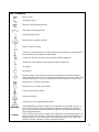
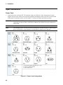
SAFETY SYMBOLS
Direct current
Alternating current
Both direct and alternating current
Three-phase alternating current
Earth (ground) terminal
Protective earth (ground) terminal
Frame or chassis terminal
Terminal is at earth potential. Used for measurement and control circuits designed to
be operated with one terminal at earth potential.
Terminal for Neutral conductor on permanently installed equipment
Terminal for Line conductor on permanently installed equipment
On (supply)
Off (supply)
Standby (supply). Units with this symbol are not completely disconnected from ac
mains when this switch is off. To completely disconnect the unit from ac mains, either
disconnect the power cord or have a qualified electrician install an external switch.
In position of a bi-stable push control
Out position of a bi-stable push control
Caution, risk of electric shock
Caution, hot surface
Caution (refer to accompanying documents)
WARNING
Caution
The WARNING sign denotes a hazard. It calls attention to a procedure, practice, or
the like, which, if not correctly performed or adhered to, could result in personal
injury. Do not proceed beyond a WARNING sign until the indicated conditions are
fully understood and met.
The CAUTION sign denotes a hazard. It calls attention to an operating procedure, or
the like, which, if not correctly performed or adhered to, could result in damage to or
destruction of part or all of the product. Do not proceed beyond a CAUTION sign
until the indicated conditions are fully understood and met.
5
Declaration of Conformity
To obtain the latest Declaration of Conformity, go to http://regulations.corporate.keysight.com and
click on “Declarations of Conformity.”
Acoustic Noise Information
Herstellerbescheinigung
Diese Information steht im Zusammenhang mit den Anforderungen der Maschinenlä
minformationsverordnung vom 18 Januar 1991.
* Schalldruckpegel Lp <70 dB(A)
* Am Arbeitsplatz
* Normaler Betrieb
* Nach EN 27779 (Typprüfung).
Manufacturer's Declaration
This statement is provided to comply with the requirements of the German Sound Emission Directive,
from 18 January 1991.
* Sound Pressure Lp <70 dB(A)
* At Operator Position
* Normal Operation
* According to EN 27779 (Type Test).
Printing History
The edition and current revision of this manual are indicated below. Reprints of this manual containing minor
corrections and updates may have the same printing date. Revised editions are identified by a new printing date.
A revised edition incorporates all new or corrected material since the previous printing date.
This document contains proprietary information protected by copyright. All rights are reserved. No part of this
document may be photocopied, reproduced, or translated into another language without the prior consent of
Keysight Technologies. The information contained in this document is subject to change without notice.
Copyright 2000, 2002, 2014 Keysight Technologies
6
Edition 1 ________ August 2000
Update 1 ________ November 2000
Update 2 ________ June 2001
Edition 2 ________ March 2002
Update 1 ________ July 2004
Update 2 ________ April 2006
Edition 3 ________ August 2014
Table of Contents
Warranty Information
Safety Summary
Declaration of Conformity
Acoustic Noise Information
Printing History
Table of Contents
3
4
6
6
6
7
QUICK REFERENCE
11
The Front Panel -At a Glance
The Rear Panel At a Glance
Instrument Configuration
Front Panel Number Entry
Front Panel Annunciators
Immediate Action Keys
Front Panel Menus - At a Glance
SCPI Programming Commands - At a Glance
GENERAL INFORMATION
Document Orientation
Safety Considerations
Options and Accessories
Description
Features and Capabilities
Front Panel Controls
Remote Programming
Operating Modes
Constant Current CC (Mode)
Constant Resistance (CR) Mode
Constant Voltage (CV) Mode
Transient Operation
List Operation
Triggered Operation
Input Control
Protection Features
Saving and Recalling Settings
External Control Signals
Remote Sensing
Monitor Outputs
External Programming Input
Fault
Port On/Off
Input Measurements
DC Measurements
RMS Measurements
Minimum and Maximum Measurements
Power Measurements
Measurement Ranges
11
12
12
13
14
14
15
17
19
19
20
20
20
21
21
21
22
22
23
24
26
27
27
30
30
33
33
33
33
33
34
34
34
35
35
35
35
35
INSTALLATION
37
Inspection
Damage
Packaging Material
Items Supplied
37
37
37
37
7
Cleaning
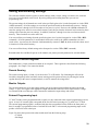
Installing the Modules
Procedure
Channel Number
Location
Bench Operation
Rack Mounting
Input Connections
Power Cord
Manually-Tightened Connectors
8mm Screw Terminal Connector (option UJ1)
Wire Considerations
Control Connector
Sense Switch
Trigger and Digital Connections
Computer Connections
GPIB Interface
RS-232 Interface
Application Connections
Local Sense Connections
Remote Sense Connections
Parallel Connections
Low Voltage Operation
TURN-ON CHECKOUT
Introduction
Checkout Procedure
In Case of Trouble
Error Messages
Selftest Errors
FRONT PANEL OPERATION
Introduction
Front Panel Description
System Keys
Function keys
Immediate Action Keys
Scrolling Keys
Metering Keys
Input Control Keys
Transient Control Keys
Trigger Control Keys
List Control Keys
Entry Keys
Examples of Front Panel Programming
1 - Using the Front Panel Display
2 - Programming Constant Current, Voltage and Resistance Modes
3 - Programming Transient Operation
4 - Programming Lists
5 - Querying and Clearing Output Protection and Errors
6 - Making Basic Front Panel Measurements
7 - Setting the GPIB Address
8 - Storing and Recalling Instrument States
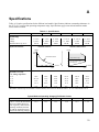
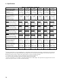
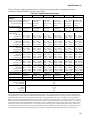
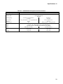
SPECIFICATIONS
8
37
38
38
39
39
41
41
42
42
43
43
44
46
47
47
48
48
48
49
49
49
49
51
53
53
53
54
54
54
55
55
55
57
58
58
59
59
60
61
61
61
62
63
63
63
65
67
69
69
70
70
71
PERFORMANCE TEST AND CALIBRATION PROCEDURES
Introduction
Equipment Required
Performance Tests
IMON Zero Verification
CC Mode Tests
CV Mode Tests
CR Mode Tests
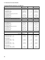
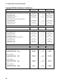
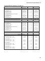
Keysight N3302A Verification Test Record
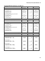
Keysight N3303A Verification Test Record
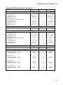
Keysight N3304A Verification Test Record
Keysight N3305A Verification Test Record
Keysight N3306A Verification Test Record
Keysight N3307A Verification Test Record
Calibration
Parameters Calibrated
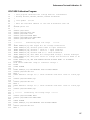
IMON, IPROG and CURRENT Calibration Program
VOLTAGE Calibration Program
RESISTANCE Calibration Program
INDEX
77
77
77
78
78
78
79
81
84
85
86
87
88
89
92
92
93
97
99
103
9
1
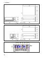
Quick Reference
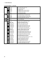
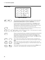
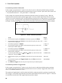
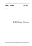
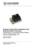
The Front Panel -At a Glance
15-character display shows
Annunciators indicate
channel, voltage and current
measurements.
System keys:
♦
♦
♦
♦
♦
operating modes and status
conditions.
1
2
Return to Local mode.
Set the GPIB address.
Set the RS-232 interface.
Display SCPI error codes.
Save and recall instrument
states.
4
3
5
N3300A
SYSTEM DC ELECTRONIC LOAD
CHANNEL
CV CC CR
VOLTS
Unr
Dis Tran
Prot
SYSTEM
Ident
Local
AMPS
Cal
Shift
Rmt
Addr Err SQR
Sense
Meter
Error
Address
Channel
Save
Recall
Prot Clear
Protect
Channel
Input
on/off
LINE
FUNCTION
Func
Current
Res
Voltage
Step
Step
List
Tran
Trigger
Trigger
Control
ENTRY
7
8
9
4
5
6
1
2
E
-
0
.
3
Input
Input
Enter
Clear Entry
ON
OFF
6
Function keys:
♦ Select metering functions.
♦ Enable/disable input.
♦ Program current, resistance and
voltage modes.
♦ Set and clear protection functions.
♦ Scroll through front panel menu
commands.
Entry keys:
♦ Enter values.
♦ Increment or decrement
values.
Turns the electronic load on
and off.
11
1 - Quick Reference
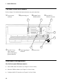
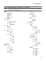
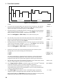
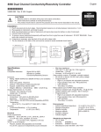
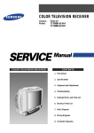
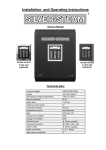
The Rear Panel At a Glance
Refer to chapter 3 for detailed information about the rear panel connections.
14-pin control
Input binding post
Standard 24-pin
connector
9-pin RS-232
GPIB connector
1
interface connector
2
3
4
5
6
7
3-pin IEC 320 ac
input connector.
(power cord requires
ground conductor)
6-pin trigger/digital
Sense switch
connector
Instrument Configuration
Use the front panel Address menu to
♦ Select GPIB or RS-232 interface (see Chapter 5 in User's Guide).
♦ Select the GPIB bus address (see Chapter 5 in User's Guide).
♦ Configure the RS-232 interface (see Chapter 5 in User's Guide).
12
Quick Reference - 1
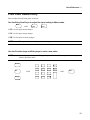
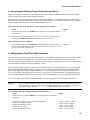
Front Panel Number Entry
Enter numbers from the front panel as follows:
Use the Entry Scroll keys to adjust the input setting in Meter mode.
Meter
AND
Input
Input
If CC is lit, the input current changes.
If CV is lit, the input voltage changes.
If CR is lit, the input resistance changes.
NOTE
The input must be on for input values to change.
Use the Function keys and Entry keys to enter a new value
NOTE
If you make a mistake use the Backspace key to delete the number, or press the Meter key to
return to the Meter mode.
Current
Res
Voltage
AND
7
8
9
4
5
6
1
2
3
E
-
0
.
Input
Input
Enter
AND
Enter
Clear Entry
13
1 - Quick Reference
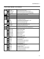
Front Panel Annunciators
φ1
A list is initiated or running.
Prot
CV
The selected input channel is in the
constant voltage (CV) mode.
The selected input channel is in the
constant current (CC) mode.
The selected input channel is in the
constant resistance (CR) mode.
Cal
CC
CR
Unr
Dis
Tran
The selected input channel is unregulated.
The input is OFF. Press the Input on/off
key to turn the input on.
The selected input channel is enabled for
transient operation.
Shift
Rmt
Indicates that a channel protection feature is active
on any channel. Press the Prot Clear key to clear
the protection condition.
Calibration mode is ON. Calibration can only be
done through the computer interface.
Indicates that the shift key has been pressed.
Addr
Err
Indicates that the electronic load is in remote state
(either GPIB or RS-232). In the remote state, only
the active key is the Local key.
The electronic load is addressed to talk or listen.
A remote programming error(s) have occurred.
SQR
The electronic load is requesting a service.
Immediate Action Keys
Input
On/Off
A toggle switch that turns the input of the electronic load on or off.
Local
Activates front panel control when the unit is in remote mode
(unless a Lockout command is in effect).
Increases the input current (CC), voltage (CV), or resistance (CR) in Meter mode.
Input
Input
Decreases the input current (CC), voltage (CV), or resistance (CR) in Meter mode.
Channel
Selects another channel.
Shift
+
Trigger
Displays any protection functions that are tripped.
Protect
Shift
+
Shift
+
Meter
14
Causes an initiate and trigger to occur. Used with transient subsystem or list.
Prot
Clear
Resets the protection circuit and allows the unit to return to its last programmed state.
Ident
Identifies the module installed in the selected channel location. (not available)
Returns the front panel to metering mode from any other mode.
Quick Reference - 1
Front Panel Menus - At a Glance
Address
Recall
Shift
Save
Shift
Shift
Error
Shift
Sense
Channel
Func
Protect
Meter
Current
Res
ADDRESS 5
INTF GPIB
BAUDRATE 300
PARITY NONE
FLOW NONE
*RCL 0
*RST
*SAV 0
ERROR 0
CHANNEL 1
S:PNT
S:TIN
S:WIN
S:OFF
S:C:RNG
S:V:RNG
FUNC
FNC:MODE
INP:SHOR
OC -- -- -RRV --- -XXXX XXXX
XXXX V MAX
XXXX V MIN
XXXX V RMS
XXXX A MAX
XXXX A MIN
XXXX A RMS
XXXX WATTS
XXXX W MAX
XXXX W MIN
CURR
C:MODE
C:RANG
C:SLEW
C:SLW:N
C:SLW:P
C:TLEV
C:TRIG
RES
R:MODE
R:RANG
R:SLEW
R:SLW:N
R:SLW:P
R:TLEV
R:TRIG
Sets the GPIB Address
Selects an interface (GPIB or RS232)
Selects baud rate (300, 600, 1200, 2400, 4800, 9600) *
Selects message parity (NONE, EVEN, ODD, MARK, SPACE) *
Selects flow control (XON-XOFF, RTS-CTS, DTR-DSR, NONE) *
Recalls the instrument state
Resets the instrument to its power-on state
Saves the present instrument state
Displays the number of errors in the SCPI error queue
Allows selection of channel to be controlled by the front panel
Defines the number of data points in the measurement
Sets the digitizer sample spacing
Sets the measurement window function (RECT, HANN)
Defines the data offset in the measurement
Selects the current measurement range
Selects the voltage measurement range
Sets the regulation mode (CURR, RES, VOLT)
Selects what controls regulating mode (FIX, LIST)
Enable/disables the input short (OFF/ON)
General protection status (overcurrent fault shown)
Voltage protection status (remote reverse voltage fault shown)
Displays the input voltage and current
Displays the maximum voltage
Displays the minimum voltage
Displays the rms voltage
Displays the maximum current
Displays the minimum current
Displays the rms current
Displays the wattage
Displays the maximum wattage
Displays the minimum wattage
Sets the input current
Sets the current mode (FIXED, LIST)
Sets the input current range
Sets current slew rate
Sets current slew rate for negative transitions
Sets current slew rate for positive transitions
Sets the transient input current
Sets the triggered input current
Sets the input resistance
Sets the resistance mode (FIXED, LIST)
Sets the input resistance range
Sets resistance slew rate
Sets resistance slew rate for negative transitions
Sets resistance slew rate for positive transitions
Sets the transient input resistance
Sets the triggered input resistance
*Only applicable for use with RS-232
15
1 - Quick Reference
Front Panel Menus - continued
Voltage
Tran
Trigger
List
16
VOLT
V:MODE
V:RANG
V:SLEW
V:SLW:N
V:SLW:P
V:TLEV
V:TRIG
TRAN
T:DCYC
T:FREQ
T:MODE
T:TWID
INIT:IMMED
ABORT
LST:STEP
LST:CNT
DWEL:0 EOL
CURR:0 EOL
C:RANG:0 EOL
C:SLEW:0 EOL
C:SLW:N:0 EOL
C:SLW:P:0 EOL
C:TLEV:0 EOL
FUNC:0 EOL
RES:0 EOL
R:RANG:0 EOL
R:SLEW:0 EOL
R:SLW:N:0 EOL
R:SLW:P:0 EOL
R:TLEV:0 EOL
TRAN:0 EOL
T:DCYC:0 EOL
T:FREQ:0 EOL
T:MODE:0 EOL
T:TWID:0 EOL
VOLT:0 EOL
V:RANG:0 EOL
V:SLEW:0 EOL
V:SLW:N:0 EOL
V:SLW:P:0 EOL
V:TLEV:0 EOL
Sets the input voltage
Sets the voltage mode (FIXED, LIST)
Sets the input voltage range
Sets voltage slew rate
Sets voltage slew rate for negative transitions
Sets voltage slew rate for positive transitions
Sets the transient input voltage
Sets the triggered input voltage
Enables/disables the transient generator (OFF/ON)
Sets the transient duty cycle in continuous mode
Sets the transient frequency in continuous mode
Sets the transient mode (CONT, PULSE, TOGGLE)
Sets the transient pulse width in pulse mode
Initiates the trigger system
Aborts the initiated trigger
Sets the method of incrementing steps (ONCE, AUTO)
Specifies the number of times the list is cycled
Specifies the time period of each step
Specifies the current setting for each step
Specifies the current range for each step
Sets the current slew rate for each step
Sets the negative current slew rate for each step
Sets the positive current slew rate for each step
Sets the transient input current for each step
Sets the list regulation mode (CURR, RES, VOLT)
Specifies the resistance setting for each step
Specifies the resistance range for each step
Sets the resistance slew rate for each step
Sets the negative resistance slew rate for each step
Sets the positive resistance slew rate for each step
Sets the transient input resistance for each step
Enables/disables the transient level for each step
Sets the transient duty cycle for each step
Sets the transient frequency for each step
Sets the mode of the transient generator (CONT, PULSE)
Sets the transient pulse width for each step
Specifies the voltage setting for each step
Specifies the voltage range for each step
Sets the voltage slew rate for each step
Sets the negative voltage slew rate for each step
Sets the positive voltage slew rate for each step
Sets the transient input voltage for each step
Quick Reference - 1
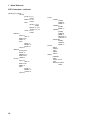
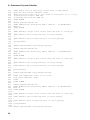
SCPI Programming Commands - At a Glance
NOTE
ABORt
CALibrate
Most [optional] commands have been omitted for clarity. Refer to the Programming Guide for a complete
description of all programming commands.
:DATA <n> [,<n>]
:IMON:LEVel <points>
:IPRog:LEVel <points>
:LEVel <points>
:PASSword <n>
:SAVE
:STATE <bool> [,<n>]
CHANnel | INSTrument
[:LOAD] <n>
INITiate
[:IMMediate]
:SEQuence[1] | :SEQuence2
:NAMe LIST | ACQuire
CONTinuous
:SEQuence1 <bool>
:NAMe LIST <bool>
INPut | OUTput
[:STATe] <bool>
:PROTection
:CLEar
:SHORt
[:STATe] <bool>
MEASure | FETCh
:ARRay
:CURRent?
:POWer?
:VOLTage?
[:SCALar]
:CURRent?
:ACDC?
:MAX?
:MIN?
:POWer?
:MAX?
:MIN?
:VOLTage?
:ACDC?
:MAX?
:MIN?
PORT0[:STATe] <bool>
PORT1[:LEVel] <n>
SENSe
:CURRent
:RANGe <n>
:SWEep
:OFFSet
:POINts <n>
:TINTerval <n>
:WINDow <type>
:VOLTage
:RANGe <n>
[SOURce:] CURRent
[:LEVel] <n>
:TRIG <n>
:MODE <mode>
:PROTection
[:LEVel] <n>
:DELay <n>
:STATe <bool>
:RANGe <n>
:SLEW
[:BOTH] <n>
:NEGative <n>
:POSitive <n>
:TLEVel <n>
FUNCtion | MODE
:MODE <mode>
LIST
:COUNt <n>
:CURRent
[:LEVel] <n> {,<n>}
:POINts?
:RANGe <n> {,<n>}
:POINts?
:SLEW
[:BOTH] <n> {,<n>}
:POINts?
:NEGative <n> {,<n>}
: POSitive <n> {,<n>}
:TLEVel <n> {,<n>}
:POINts?
:DWELI <n> {,<n>}
:POINts?
:FUNCtion | MODE <mode>
:RESistance
[:LEVel] <n> {,<n>}
:POINts?
:RANGe <n> {,<n>}
:POINts?
:SLEW
[:BOTH] <n> {,<n>}
:POINts?
:NEGative <n> {,<n>}
: POSitive <n> {,<n>}
:TLEVel <n> {,<n>}
:POINts?
:STEP <step>
:TRANsient
[:STATe] <bool> {,<bool>}
:POINts?
:DCYCle <n> {,<n>}
:POINts?
:FREQuency <n> {,<n>}
:POINts?
:MODE <mode> {<mode>}
:POINts?
:TWIDth <n> {,<n>}
:POINts?
17
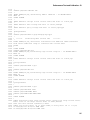
1 - Quick Reference
SCPI Commands - continued
[SOURce:]LIST (continued)
:VOLTage
[:LEVel] <n> {,<n>}
:POINts?
:RANGe <n> {,<n>}
:POINts?
:SLEW
[:BOTH] <n> {,<n>}
:POINts?
:NEGative <n> {,<n>}
: POSitive <n> {,<n>}
:TLEVel <n> {,<n>}
:POINts?
RESistance
[:LEVel] <n>
:TRIG <n>
:MODE <mode>
:RANGe <n>
:SLEW
[:BOTH] <n>
:NEGative <n>
:POSitive <n>
:TLEVel <n>
TRANsient
[:STATe] <bool>
:DCYCle <n>
:FREQuency <n>
:MODE <mode>
:TWIDth <n>
VOLTage
[:LEVel] <n>
:TRIG <n>
:MODE <mode>
:RANGe <n>
:SLEW
[:BOTH] <n>
:NEGative <n>
: POSitive <n>
:TLEVel <n>
18
STATus
SYSTem
TRIGger
:CHANnel
[:EVENt]?
:CONDition?
:ENABle <n>
:CSUMmary
[:EVENt]?
:ENABle <n>
:OPERation
[:EVENt]?
:CONDition?
:ENABle <n>
:NTRansition <n>
:PTRansition <n>
:QUEStionable
[:EVENt]?
:CONDition?
:ENABle <n>
:ERRor?
:VERSion?
:LOCal
:REMote
:RWLock
[:IMMediate]
:DELay
:SOURce <source>
:TIMer
:SEQuence2 | ACQuire
:COUNt
2
General Information
Document Orientation
This manual describes the operation of the Keysight Model N3300A, N3301A, N3302A, N3303A N3304A,
N3305A, N3306A and N3307A DC Electronic Loads. Unless otherwise noted, all units will be referred to by
the description "electronic load" throughout this manual. The following documents and software are shipped
with your electronic load:
♦ A User's Guide (this document), contains installation, checkout and front panel information.
♦ A Programming Guide, contains detailed GPIB programming information.
The following Getting Started Map will help you find the information you need to complete the specific task
that you want to accomplish. Refer to the table of contents or index of each guide for a complete list of the
information contained within.
Getting Started Map
Task
Installing the unit
Line voltage connections
Installing modules
Load connections
Checking out the unit
Verifying proper operation
Using the front panel
Calibrating the unit
Using the front panel
Front panel keys
Front panel examples
Using the programming interface
GPIB interface
RS-232 interface
Programming the unit using SCPI commands
SCPI commands
SCPI programming examples
Programming the unit using VXIplug&play
instrument driver
Installing the instrument driver
Instrument driver functions
C/C++ example programs
Visual BASIC example programs
Lab VIEW example programs
Keysight VEE example programs
Where to find information
User's Guide
User's Guide
User's Guide
User's Guide
Programming Guide
Programming Guide
VXIplug&play on-line help
NOTE:
The driver must be installed on your computer to
access the on-line information.
Drivers for Keysight instruments are available on the
web at www.keysight.com/find/drivers
19
2 - General Information
Safety Considerations
This electronic load is a Safety Class 1 instrument, which means it has a protective earth terminal. That terminal
must be connected to earth ground through power source equipped with a ground receptacle. Refer to the Safety
Summary page at the beginning of this guide for general safety information. Before installation or operation,
check the electronic load and review this guide for safety warnings and instructions. Safety warnings for
specific procedures are located at appropriate places in the Guide.
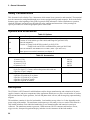
Options and Accessories
Option
800
908
909
UJ1
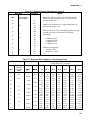
Table 2-1 Options
Description
One rack mount kit for two N3301A half-rack units side by side*.
Consists of: Lock-link kit (p/n 5061-9694) and Flange kit (p/n 5062-3978)
One rack mount kit*.
Consists of: Flange kit for N3300A (order 2 p/n 5062-3974)
Flange kit for one N3301A with blank filler panel (p/n 5062-3960)
One rack mount kit with handles for N3300A* (order 2 p/n 5062-3975).
8mm input screw terminal connectors (see chapter 3)
*Support rails (p/n E3663AC) are required.
Table 2-2 Accessories
GPIB cables
1.0 meter (3.3 ft)
2.0 meters (6.6 ft)
4.0 meters (13.2 ft)
0.5 meters (1.6 ft)
RS-232 cable
(9-pin F to 9-pin F, 2.5 meter, null modem/printer cable with one
9-pin M to 25 pin F adapter)
RS-232 adapter kit (contains 4 adapters)
9-pin M to 25-pin M for pc or printer
9-pin M to 25-pin M for pc or printer
9-pin M to 25-pin M for modem
9-pin M to 9-pin M for modem
Keysight Part Number
10833A
10833B
10833C
10833D
34398A
34399A
Description
The N3300A is a DC Electronic Load Mainframe used for design, manufacturing, and evaluation of dc power
supplies, batteries, and power components. Other applications include use as a power circuit breaker or crowbar,
high current function or pulse generator, fuel-cell and photovoltaic cell test, and de-energizing superconducting
magnets.
The mainframe contains six slots for load modules. Load modules occupy either 1 or 2 slots depending on the
power rating of the module. The mainframe can dissipate up to 300 watts per slot, to a total of 1800 watts for a
fully loaded mainframe. Each individual module has its own channel number and contains its own input
connector. The mainframe contains a processor, GPIB connector, RS-232 connector and interface circuits,
trigger circuits, front-panel keypad and display, and other circuits common to all the load modules.
20
General Information - 2
The N3301A is a DC Electronic Load Mainframe that is functionally identical to the N3300A, but is a half-rack
width with only two slots for load modules. The mainframe can dissipate up to 300 watts per slot, to a total of
600 watts for a fully loaded mainframe.
The N3302A, N3303A N3304A, N3305A, N3306A and N3307A are electronic load modules that can be
installed in the N3300A and N3301A mainframes. The module specific pages in Appendix A include
specifications and other information pertinent to a particular model. Each module can operate independently in
constant current (CC) mode, constant voltage (CV) mode, or constant resistance (CR) mode. In addition, each
input can be turned on or off (open-circuited), or short-circuited.
Features and Capabilities
♦
♦
♦
♦
♦
♦
♦
♦
♦
Constant current (CC), constant voltage (CV), or constant resistance (CR) mode operation.
Built-in GPIB and RS-232 interface programming with SCPI command language.
Triggered input and measurement functions.
Front panel control with keypad.
Independent channel operation.
Built-in pulse generator for continuous, pulsed, and toggled transient operation.
Overvoltage, overcurrent, overpower, and overtemperature protection.
Extensive selftest, status reporting and software calibration.
Fan speed control for reduced acoustic noise under light load conditions.
Front Panel Controls
The front panel has keyboard controls for setting the input voltage, current and resistance. The panel display
provides digital readouts of a number of functions including the inputs. Annunciators display the operating
status of the electronic load. System keys let you perform system functions such as setting the GPIB address
and recalling operating states. Front panel function keys access the electronic load function menus. Front panel
Entry keys let you select and enter parameter values. Refer to chapter 5 for a complete description of the front
panel controls.
Remote Programming
The electronic load may be remotely programmed via the GPIB bus and/or an RS-232 serial port. GPIB
programming is done with SCPI (Standard Commands for Programmable Instruments) commands, which make
the electronic load programs compatible with those of other GPIB instruments that are also SCPI compatible.
Local (front panel) control is in effect immediately after power is applied. The front panel keypad and display
allow manual control of each individual module when the electronic load is used in bench test applications.
Remote (computer) control goes into effect (front panel Rmt annunciator is on) as soon as the mainframe
receives a command via the GPIB. A built-in GPIB interface and SCPI commands allow control and readback
of all functions when the electronic load is used in computer controlled applications.
With remote control in effect, only the computer can control the electronic load; the front panel keypad has no
effect. You can still use the front panel display to view the input voltage and current readings. To return the
electronic load to local control, press the Local key. This will return the electronic load to local control, unless
the local-lockout command has been received from the GPIB controller.
Most functions that can be performed remotely over the GPIB or RS-232 can also be performed from the front
panel. Whenever possible the function menu commands reflect their corresponding SCPI commands. Thus,
learning to operate the electronic load from the front panel will aid you when writing computer programs.
21
2 - General Information
Operating Modes
The three modes of operation are:
♦ Constant current (CC).
♦ Constant voltage (CV).
♦ Constant resistance (CR).
When programmed to a mode, a module remains in that mode until the mode is changed or until a fault
condition, such as an overpower or overtemperature, occurs.
The current, resistance, and voltage mode parameters described in subsequent paragraphs can be programmed
whether or not the mode is presently selected. When a mode is selected via the front panel or via the GPIB or
RS-232, most of the associated parameters will take effect at the input (exceptions are noted in the mode
descriptions).
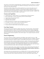
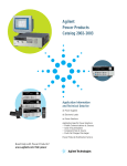
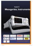
Constant Current CC (Mode)
In this mode, the module will sink a current in accordance with the programmed value regardless of the input
voltage (see Figure 2-1). The CC mode can be set with front panel keys or via the GPIB or RS-232. The CC
mode parameters are discussed in the following paragraphs.
Figure 2-1. Constant Current Mode
Ranges
Current may be programmed in either of two overlapping ranges, a Low range and a High range. The low range
provides better resolution at low current settings. The range can be set at the front panel or via the GPIB
(CURR:RANG command). The electronic load selects the range that corresponds to the range value that you
program. If the range value falls in a region where ranges overlap, the electronic load selects the Low range. If
the present input setting is outside the Low range, the electronic load will automatically adjust the input setting
to the highest value available in the Low range. If you subsequently program an input value that is outside the
Low range, an OUT OF RANGE message will appear on the front panel display.
Immediate Current Level
The current level can be set at the front panel or via the GPIB (CURR command). If the CC mode is the active
mode, the new setting immediately changes the input at a rate determined by the slew setting (described below).
If the module is not in the CC mode, the new setting is saved for use when the mode is changed to CC.
22
General Information - 2
Triggered Current Level
A current level can be preset (stored in the electronic load) allowing the input to be updated when a trigger is
received instead of immediately as described above.
If the CC mode is the active mode, the preset current level will become the actual value and the input will be
updated when a trigger occurs. If the CC mode is not the active mode, the preset current level will become the
actual value when a trigger occurs but there will be no effect on the input until the CC mode becomes active.
Once a level is triggered, subsequent triggers will have no effect on the input unless another CURR:TRIG
command is sent. The trigger sources available to the electronic load are described later in this chapter. The
electronic load has a status reporting capability to keep track of pending triggers and other operating conditions.
The status reporting capability is described in detail in the Programming Guide.
Transient Current Level
The transient current level can be set at the front panel or via the GPIB. The transient current level can be
higher or lower than the main current level. The module input will switch between the main level and the
transient level when transient operation is turned on.
Software Current Limit
The electronic load allows the user to set a current limit (0 to 102% of full scale) for each module via the GPIB
(CURR:PROT command) which will shut down the input if the current limit is exceeded beyond a
programmable time delay. Note that the software current limit is in effect for any mode of operation (not just
the CC mode). The software current limit feature is described later in this chapter under Protection Features.
Slew Rate
The current slew rate determines the rate at which the input current to a module changes to a new programmed
value. Current slew rates are programmed in amperes per second. Slew rates can be set at the front panel or via
the GPIB (CURR:SLEW command). The programmed slew rate remains in effect for the immediate, triggered,
and transient level changes previously described.
Any slew rate can be programmed provided that it falls between the fastest and the slowest slew rates shown in
Figure 2-8A. If a value is programmed that is outside these limits, the module will automatically adjust the
programmed value to either the fastest or the slowest slew rates shown in the figure.
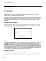
Constant Resistance (CR) Mode
In this mode, the module will sink a current linearly proportional to the input voltage in accordance with the
programmed resistance (see Figure 2-2). The CR mode can be set at the front panel or via the GPIB
(MODE:RES command). The CR mode parameters are described in the following paragraphs.
Ranges
Resistance may be programmed in any of four overlapping ranges. The range can be set at the front panel or via
the GPIB (RES:RANG command). The electronic load selects the range that corresponds to the range value that
you program. If the range value falls in a region where ranges overlap, the electronic load selects the range with
the highest resolution. If the present input setting is outside the range that you select, the electronic load will
automatically adjust the input setting to the closest available value within the newly selected range. If you
subsequently program an input value that is outside the newly selected range, an OUT OF RANGE message will
appear on the front panel display.
23
2 - General Information
Figure 2-2. Constant Resistance Mode
Immediate Resistance Level
The resistance level can be set at the front panel or via the GPIB (RES command). If the CR mode is active, the
new setting immediately changes the input at a rate determined by the voltage or current slew setting (see
description below). If the module is not in the CR mode, the new setting is saved for use when the mode is
changed to CR.
Triggered Resistance Level
A resistance level can be preset (stored in the electronic load) allowing the input to be updated when a trigger is
received instead of immediately as described above.
If the CR mode is active, the preset resistance level will become the actual value and the input will be updated
when a trigger occurs. If the CR mode is not the active mode, the preset resistance level will become the actual
value when a trigger occurs but there will be no effect on the input until the CR mode becomes active. Once a
level is triggered, subsequent triggers will have no effect on the input unless another RES:TRIG command is
sent.
Transient Resistance Level
The transient resistance level can be set at the front panel or via the GPIB (RES:TLEV command). The
transient level and the main level are used in transient operation, which is described later in this chapter.
Slew Rate
The resistance slew rate determines the rate at which the input resistance to a module changes to a new
programmed value. Resistance slew rates are programmed in ohms per second. Slew rates can be set at the front
panel or via the GPIB (RES:SLEW command). The programmed slew rate remains in effect for the immediate,
triggered, and transient level changes previously described.
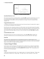
Constant Voltage (CV) Mode
In this mode, the module will attempt to sink enough current to control the source voltage to the programmed
value (see Figure 2-3). The module acts as a shunt voltage regulator when operating in the CV mode. The CV
mode can be set at the front panel or via the GPIB (MODE:VOLT command). The CV mode parameters are
described in the following paragraphs.
Ranges
Voltage may be programmed in either of two overlapping ranges, a low range and a high range. The low range
provides better resolution at low voltage settings. The range can be set at the front panel or via the GPIB
24
General Information - 2
(VOLT:RANG command). The electronic load selects the range that corresponds to the range value that you
program. If the range value falls in a region where ranges overlap, the electronic load selects the Low range. If
the present input setting is outside the Low range, the electronic load will automatically adjust the input setting
to the highest value available in the Low range. If you subsequently program an input value that is outside the
Low range, an OUT OF RANGE message will appear on the front panel display.
Figure 2-3. Constant Voltage Mode
Immediate Voltage Level
The voltage level can be set at the front panel or via the GPIB (VOLT command). If the CV mode is active, the
new setting immediately changes the input at a rate determined by the voltage slew setting. If the module is not
in the CV mode, the new setting is saved for use when the mode is changed to CV.
Triggered Voltage Level
The voltage level can be preset (stored in the electronic load) allowing the input to be updated when a trigger is
received instead of immediately as described above.
If the CV mode is the active mode, the preset current level will become the actual value and the input will be
updated when a trigger occurs. If the CV mode is not the active mode, the preset current level will become the
actual value when a trigger occurs, but there will be no effect on the input until the CV mode becomes active.
Once a level is triggered, subsequent triggers will have no effect on the input unless another VOLT:TRIG
command is sent.
Transient Voltage Level
The transient voltage level can be set at the front panel or via the GPIB (VOLT:TLEV command). The module
input will switch between the main level and the transient level when transient operation is turned on. The
transient voltage level determines the higher voltage level.
Slew Rate
The voltage slew rate determines the rate at which the input voltage to a module changes to a new programmed
value. Voltage slew rates are programmed in volts per second. Slew rates can be set at the front panel or via the
GPIB (VOLT:SLEW command). The programmed slew rate remains in effect for the immediate, triggered, and
transient level changes previously described.
Any slew rate can be programmed provided that it falls between the fastest and the slowest slew rates shown in
Figure 2-8B. If a value is programmed that is outside these limits, the module will automatically adjust the
programmed value to either the fastest or the slowest slew rates shown in the figure.
25
2 - General Information
Transient Operation
Transient operation enables the module to periodically switch between two load levels, as might be required for
testing power supplies. A power supply's regulation and transient characteristics can be evaluated by monitoring
the supply's output voltage under varying combinations of load levels, frequency, duty cycle, and slew rate.
Transient operation can be turned on and off at the front panel or via the GPIB (TRAN ON and TRAN OFF
commands). Before you turn on transient operation, you should set the desired mode of operation as well as all
of the parameters associated with transient operation. Transient operation may be used in the CC, CR, or CV
modes and can be continuous, pulsed, or toggled.
Continuous
Generates a repetitive pulse stream the toggles between two load levels.
Pulse
Generates a load change that returns to its original state after some time period.
Toggled
Generates a repetitive pulse stream that toggles between two load levels. Similar to
Continuous mode except that the transient points are controlled by explicit triggers instead of
an internal transient generator.
Continuous Transient Operation
In continuous operation, a repetitive pulse train switches between two load levels. In the front panel, the
transient commands are located under the TRAN key. Continuous transient operation is selected via the GPIB
using the TRAN:MODE CONT command.
The two load levels in the transient operation are the previously described main level (immediate or triggered)
and transient level for current, resistance, or voltage. The rate at which the level changes is determined by the
slew rate (see slew rate descriptions for CV, CR, or CV mode as applicable). In addition, the frequency and
duty cycle of the continuous pulse train are programmable. The frequency can be set from 0.25 to 10000 Hz at
the front panel or via the GPIB (TRAN:FREQ command). The duty cycle can be set from 3% to 97% (0.25 Hz
to 1 kHz) or from 6% to 94% (above 1 kHz) at the front panel or via the GPIB (TRAN:DCYC command).
Pulsed Transient Operation
Pulsed transient operation is similar to continuous operation with the following exceptions:
a. In order to get a pulse, an explicit trigger is required. The trigger can be an external trigger signal
received via the TRIGGER input on the rear panel, the TRIG:SOUR function, the *TRG or TRIG
commands, the ac line, the internal timer signal, or the front panel Trigger key.
b. One pulse results from each trigger. Therefore, frequency cannot be programmed. The main level,
transient level, and slew rate are programmed as described for continuous operation. The pulse width is
programmable from 0.00005 to 4 seconds via the GPIB (TRAN:TWID command).
Toggled Transient Operation
Toggled transient operation causes the module input to alternate between two pre-defined levels as in
continuous operation except that the transient points are controlled by explicit triggers instead of the internal
transient generator. As in pulsed transient operation, the trigger signal can be an external trigger signal, the
GPIB GET function, the *TRG command, the TRIG command, or the ac line or internal timer signals.
26
General Information - 2
List Operation
List mode lets you generate complex sequences of input changes with rapid, precise timing, which may be
synchronized with internal or external signals. This is useful when running test sequences with a minimum
amount of programming overhead.
You can program up to 50 settings (or steps) in the list, the time interval (dwell) that each setting is maintained,
the number of times that the list will be executed, and how the settings change in response to triggers. All listed
data is stored in a non-volatile memory when the *SAV command is executed. This means that the programmed
data for any list will be retained when the electronic load is turned off. Note that lists data can only be saved in
nonvolatile memory locations 0, 7, 8, or 9. List data will not be saved in other memory locations. Use the *RCL
command to recall the saved state.
List steps can be either individually triggered, or paced by a separate list of dwell times which define the
duration of each step. Therefore, each of the up to 50 steps has an associated dwell time, which specifies the
time (in seconds) that the input remains at that step before moving on to the next step. See chapter 5 for detailed
information about programming lists from the front panel.
Triggered Operation
The electronic load has various triggering modes to allow synchronization with other test equipment or events.
The triggering circuits are located in the mainframe, and all modules receive the trigger simultaneously
(although each module is programmed individually as to what operation, if any, will be triggered. As described
previously, triggering can be used for the following applications:
Triggering a preset level
Transfers all pending preset levels to the actual level. For the presently active
mode, the new level appears at the input. For the modes which are not presently
active, the preset levels will not take effect at the input until the applicable
mode becomes active.
Triggering a transient pulse
Generates a transient pulse of programmable width when pulsed transient
operation is in effect.
Toggling
Changes the input between the main level and the transient level when toggled
transient operation is in effect.
Triggers can be sent from the front panel by pressing the Trigger key. However you must first initiate the
trigger function by executing the TRIG:IMMED command located in the Trigger Control menu.
Three triggering methods are available over the GPIB: the GET function, the *TRG common SCPI command,
and the TRIG subsystem SCPI command (refer to Programming Guide). The SCPI TRIG subsystem allows
you to select either the ac line frequency, internal timer, or TRIG command as the trigger source. There is also
a TRIGGER connector on the rear panel for external trigger inputs.
*TRG and the TRIG command are both synchronous with other commands; that is, the modules are not
triggered until pending operations are completed. GET, external triggers, ac-line triggers, and internal-timer
triggers are all asynchronous; that is, the modules are triggered as soon as the trigger signal is received.
27
2 - General Information
If the ac line is selected via the GPIB as the trigger source, triggers will be generated once for each cycle of ac
input power. An ac line frequency of 60 Hz produces a trigger period of 16.67 ms; 50 Hz line frequency
produces a trigger period of 20 ms.
The rear-panel TRIGGER connector also provides a trigger output signal. This signal is generated
synchronously with the trigger signal sent by the mainframe to the modules. The trigger output signal can be
used to trigger an external device such as an oscilloscope, DVM, or another electronic load mainframe.
The electronic load has a status reporting capability to keep track of trigger operations. Refer to 'Status
Reporting' in the Programming Guide.
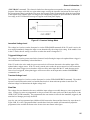
Slew Rate and Minimum Transition Time
Slew rate is defined as the change in current, resistance, or voltage over time. A programmable slew rate allows
a controlled transition from one load setting to another to minimize induced voltage drops on inductive power
wiring, or to control induced transients on a test device (such as would occur during power supply transient
response testing).
In cases where the transition from one setting to another is large, the actual transition time can be calculated by
dividing the voltage or current transition by the slew rate. The actual transition time is defined as the time
required for the input to change from 10% to 90% or from 90% to 10% of the programmed excursion. In cases
where the transition from one setting to another is small, the small signal bandwidth of the load limits the
minimum transition time for all programmable slew rates. Because of this limitation, the actual transition time is
longer than the expected time based on the slew rate, as shown in Figure 2-7.
Voltage,
Current, or
Resistance
Change
100%
Slew Rate
90%
10%
0%
Time
Expected Time
Actual Time
Figure 2-7. Risetime Transition Limitation
28
General Information - 2
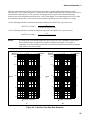
Therefore, both minimum transition time and slew rate must be considered when determining the actual
transition time. This is shown in Figure 2-8, which shows the minimum transition time for a given slew rate as a
horizontal line, and at about a 13.3% or greater load change, the slew rate increases from the minimum
transition time to the Maximum transition time at a 100% load change. The actual transition time will be either
the minimum transition time, or the total slew time (transition divided by slew rate), whichever is longer.
Use the following formula to calculate the minimum transition time (MinTT) for a given slew rate:
MinTT (in seconds) =
__________8__________
slew rate (in amps/second)
Use the following formula to calculate the maximum transition time (MaxTT) for a given slew rate:
MaxTT (in seconds) =
NOTE:
__________60__________
slew rate (in amps/second)
In voltage mode, all minimum transition times are based on a low-capacitance current source.
These transition times are affected by capacitive loading of the inputs. For example, a
capacitance of 2.2 microfarads increases the 85 microsecond minimum transition time (shown
in the table) to 110 microseconds.
Maximum
Minimum
Transition
Time
60000µ s
Sl
ow
es
tS
le
w
Sl
ow
es
tS
le
w
R
at
e
60000µ s
R
at
e
Maximum
Minimum
Transition
Time
8000µ s
8000µ s
6000µ s
Sl
ew
Sl
ew
R
at
e
R
at
e
A
A
6000µ s
800µ s
∆ Time
800µ s
600µ s
Fa
st
es
t
Sl
ew
Sl
ew
R
at
e
R
at
e
B
B
600µ s
85µ s
80µ s
120µ s
R
at
e
C
60µ s
Sl
ew
∆ Time
12µ s
5%
13.3%
16.7%
st
ste
Fa
50%
∆ Current (% of full scale)
A.
100%
16µ s
5%
13.3%
16.7%
50%
∆ Voltage (% of full scale)
100%
B.
Figure 2-8. Transition Time Slew Rate Examples
29
2 - General Information
Input Control
Short On/Off
A module can simulate a short circuit at its input by turning the load on with full-scale current. The short circuit
can be toggled on/off at the front panel using the SHORT command in the Func menu, or via the GPIB
(INPUT:SHORT ON|OFF command). The short on/off change uses the slew rate setting of the active mode
and range.
The actual value of the electronic short is dependent on the mode and range that are active when the short is
turned on. In CV mode it is equivalent to programming zero volts. In CC mode it is equivalent to programming
full-scale current for the present current range. In CR mode it is equivalent to programming the minimum
resistance for the present resistance range.
Note that turning the short on in CV mode may cause the load to draw so much current that the software current
limit operates, which may turn the input off.
Turning the short circuit on does not affect the programmed settings, and the load input will return to the
previously programmed values when the short is turned off.
Input On/Off
A module's input can be toggled on/off at the front panel, or via the GPIB (INPUT ON|OFF command). The
input on/off change does not use the slew rate setting so the input will change at the maximum slew rate.
Turning the input off (zero current) does not affect the programmed settings. The input will return to the
previously programmed values when the input is turned on again. Note that the Input On/Off command
supersedes the mode commands and Short On/Off command.
Protection Features
Each load module includes the following protection features:
• Overvoltage.
• Overcurrent (hardware and software).
• Overpower.
• Overtemperature.
• Reverse Voltage.
The appropriate bit(s) in the mainframe's status registers are set when any of the above protection features are
active. Also, the Prot annunciator comes on and the front-panel alphanumeric display indicates which
condition(s) have been detected. For example, if an overtemperature (OT) condition has been detected causing a
module's input to be turned off (protection shutdown, PS), the display will indicate "PS OT".
Resetting Latched Protection
All of the protection features latch (remain set) when they are tripped, except for the hardware overcurrent and
reverse voltage. The latched protection features can be reset via the GPIB (*RST or INP:PROT:CLE
commands) or at the front panel. Of course, the condition that caused the protection feature to trip must be
removed or it will trip again as soon as it is reset.
30
General Information - 2
Caution
To protect the electronic load from possible damage, the input voltage must not exceed the
maximum input voltage rating specified in the module-specific pages supplied with each
module. Never apply the ac line voltage to a module's input connectors.
Overvoltage
The overvoltage protection circuit is set at a predetermined voltage level, which cannot be changed. If the
overvoltage circuit has tripped, the module will attempt to limit the voltage level by drawing current from the dc
source. The module limits the value of current drawn such that the resulting power is within the power rating.
The overvoltage (OV) and voltage fault (VF) status register bits are set when the OV condition occurs, and will
remain set until they are reset as previously described.
An overvoltage condition does not cause the module's input to be turned off. However, a Fault signal (pin A6)
output at the module's rear-panel control connector will indicate when either an overvoltage condition or a
reverse voltage condition has occurred. The Fault signal is latched true (high TTL level) when the VF bit in the
status register goes true. The Fault output signal can be used to trip an external circuit breaker or control a relay
in order to disconnect the electronic load input from the source it is testing when an overvoltage or a reverse
voltage condition occurs.
Overcurrent
The electronic load includes both hardware and software overcurrent protection features.
Hardware. When operating in the CR or CV mode, it is possible for a module to attempt to sink more current
than it is rated for. Under this condition, the load current will be limited by a current limit circuit, which is set at
a value slightly above the current rating of the module. It protects both the electronic load and the device under
test from operating too far beyond specified limits. The hardware current limit circuit does not turn the module's
input off. The overcurrent (OC) bit in the status register is set when an OC condition occurs, and is reset when
the OC condition is removed.
Software. In addition to the hardware overcurrent protection circuit, the electronic load allows the user to
define a current protection limit in software, which will shut down a module's input if the limit is exceeded.
This feature can only be programmed via the GPIB. It is turned on/off using the CURR:PROT:STATE
ON|OFF command. The software current limit level (in amps) is set using the CURR:PROT command. A
programmable delay (in seconds) before trip is also provided with the CURR:PROT:DEL command. If the
software overcurrent limit is exceeded and persists beyond the specified delay time, the module is turned off.
Also, for these conditions, the OC and PS (protection shutdown) status register bits are set and will remain set
until the OC condition is removed and the bits are reset as previously described.
Overpower
The power-limit boundary is set by software that monitors the input current and voltage. If the input power
exceeds the power limit, the load module sets the overpower status bit, which will reset if the overpower
condition ceases. If the overpower condition persists for 3 seconds, the load module's input circuit turns off, and
the OP and PS status bits are both latched on. The input circuit remains off, and the OP and PS status bits
remain set, until protection clear occurs. Of course, if the overpower condition is not corrected, the load will
turn off again.
Overtemperature
Each module has an overtemperature (OT) protection circuit, which will turn off the input if the internal
temperature exceeds safe limits. If the OT circuit activates, the OT and PS status register bits are set and will
31
2 - General Information
remain set until they are reset. If the OT condition still exists when the reset is executed, the module's input will
remain off. You must wait until the module cools down before you can reset the OT circuit. The fan(s) will
continue to operate to cool the unit as quickly as possible.
Reverse Voltage
Caution
This feature protects the load module in case the input dc voltage lines are connected with the
wrong polarity. If a reverse voltage (LRV or RRV) condition is detected, turn off power to the
dc source and the electronic load and make the correct connections.
The electronic load conducts reverse current when the polarity of the dc source connection is incorrect. The
reverse voltage (LRV for local reverse voltage; RRV for remote reverse voltage) and voltage fault (VF) bits in
the status register are set when reverse voltage is applied. When the reverse voltage is removed the LRV and
RRV bits are cleared. However, the VF bit remains set until it is reset. As previously described, the Fault
output signal at the control connector tracks the state of the VF bit. The Fault signal can be used to control an
external relay in order to disconnect the module from the dc source if an RV condition occurs. This feature also
detects reverse voltage at the Sense terminals.
Reading Remote Programming Errors
Remote programming errors can be read via the GPIB (SYST:ERR? query) or at the front panel. The Err
annunciator indicates when remote programming errors have occurred. The errors are negative numbers
grouped into blocks of 100 as follows:
-lxx
Command errors
-2xx
Execution errors
-3xx
Device-specific errors
-4xx
Query errors
The SYST:ERR? query reads back the errors in the order in which they occurred (the error queue can hold up
to 30 entries). Once the error is read back it is removed from the list. A value 0 indicates there is no error; and
0 will be returned when all errors in the list have been read. Pressing the Error key displays just the error
number. The SYST:ERR? query returns the error number and a short description of the error to the computer.
Refer to Appendix B in the Programming Guide.
Local programming errors generated by front panel operations are not put into the error list, but are immediately
put on the electronic load's front panel display; e.g., 'OUT OF RANGE'.
Status Reporting
The electronic load incorporates a status reporting capability. Various status conditions within the electronic
load can be reported using this capability. The user determines which condition(s) will be reported. Chapter 5
of the Programming Guide describes each of the status registers in the electronic load. (These registers,
including the channel status registers, are all maintained in the mainframe.) Notice that the same information is
available in both the channel status and questionable status registers, but the channel registers are organized by
channel, and the questionable registers are organized by fault. Therefore, depending on which channels and/or
faults are most critical in your application, you can use one branch to localize selected faults quickly, and use
the other branch for broader fault reporting. By knowing that only a particular fault (questionable branch) or a
particular channel (channel branch) is enabled to initiate a service request, you can eliminate the need to read
one or more registers to locate a fault.
32
General Information - 2
Saving and Recalling Settings
The electronic load has internal registers in which settings (mode, current, voltage, resistance, slew, transient
level, etc.) for each module can be saved. By saving settings and recalling them later you can save
programming time.
The present settings for all channels are saved in the specified register (0 to 9) at the front panel or via the GPIB
(*SAV command). All of the settings are saved in the specified location in the mainframe's memory. Settings
saved in locations 1 through 6 will be lost when ac line power is cycled. However, the *SAV 0 command will
cause the settings to be stored in a non-volatile memory; and, the next time the electronic load is turned on, these
settings will become the power-on settings. In addition, locations 7 through 9 are also saved in non-volatile
memory. These locations are used to store lists.
You can recall the saved settings from the specified register (0 to 9) at the front panel or via the GPIB (*RCL
command). All of the parameters for each module which were saved by the *SAV command are set to the
saved values. At power-on, the electronic load automatically executes a *RCL 0, which recalls the values saved
in location 0 of non-volatile memory.
You can recall the factory default settings at the front panel or via the GPIB (*RST command).
Remember that Save and Recall operate on all channels, not just the presently addressed or selected channel.
External Control Signals
Each module has a 14-pin connector mounted on its rear panel. These signals are described in the following
paragraphs. See Chapter 3 for connection details.
Remote Sensing
The remote sensing inputs, + S and - S, can be used in CV or CR modes. By eliminating the effect of the
inevitable voltage drop in the load leads, remote sensing provides greater accuracy by allowing the load to
regulate directly at the source's output terminals, as well as measure the voltage there.
Monitor Outputs
The current monitor (pin A11) and voltage monitor (pin A10) output signals indicate the input current and
voltage. A 0-to-+10V signal at the appropriate output indicates the zero-to-full scale input current or voltage.
An external DVM or oscilloscope can be connected to monitor the input voltage and current.
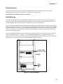
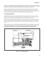
External Programming Input
CC and CV modes can be programmed with a signal (ac or dc) connected to the external programming (pin A8)
input. A 0-to-10V external signal corresponds to the 0-to-full scale input range in CV mode or in CC mode.
The external programming signal is combined with the value programmed via the GPIB or the front panel, so
that, for example, a programmed value of one-half full scale and a 5-volt external programming input would
produce a full-scale value at the input.
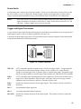
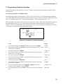
Figure 2-9 shows the input waveform that would result from the following setup:
CC Mode
60A Range
33
2 - General Information
20A Input (programmed via GPIB or front panel)
± 1V (2 V peak-peak) 1 kHz external programming signal
The external programming signal (+ 1 and - 1 volt) corresponds to + 6 and - 6 amps at the input (1 volt external
programming input = 1/10 full scale). Therefore, the input varies ± 6A at the 20A level.
Fault
The Fault signal becomes active if an overvoltage or reverse voltage occurs at the input, as described in the
Protection Features paragraphs.
Figure 2-9. External Programming Example
Port On/Off
Port is a general purpose output port that can be used to control an external device such as a relay for power
supply test purposes. The output is toggled on and off via the GPIB (PORT0 ON | OFF command). It cannot
be controlled from the front panel.
The Port output signal is a TTL compatible signal that becomes active (high level) when the PORT command is
programmed ON and becomes inactive (low level) when the PORT command is programmed OFF.
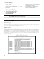
Input Measurements
Each module's input current, voltage, and power are continuously measured at the front panel.
With remote control in effect, a module may be instructed to measure its dc input voltage, current, or power by
sending the appropriate query command (e.g. MEAS:CURR). The results will be read back when the
electronic load is addressed to talk. Voltage and current measurements are performed with approximately 16-bit
resolution of full-scale ratings. Power is computed from this information. Voltage and current are measured
simultaneously, so that power data is correct.
All measurements are performed by digitizing the instantaneous input voltage or current for a defined number of
samples and sample interval, storing the results in a buffer, and then calculating the measured result. Many
parameters of the measurement are programmable. These include the number of samples, the time interval
between samples, and the method of triggering. Note that there is a tradeoff between these parameters and the
speed, accuracy, and stability of the measurement in the presence of noise. This is described in the
Programming Guide.
34
General Information - 2
As shipped from the factory, front panel measurements for input voltage and current are calculated from a total
of 1000 readings taken at a 10 microsecond sampling rate. There are no trigger controls for front panel
measurements. However, you can program both the sampling rate and the number of data points in each front
panel measurement using commands in the Sense menu. With this flexibility, measurement accuracy can be
improved for waveforms with frequencies as low as several Hertz. The sample buffer size may be varied from 1
to 4096 data points. The sampling rate may be varied from 0.00001 seconds to 0.032 seconds. Values are
rounded to the nearest 10-microsecond interval.
DC Measurements
DC voltage and current is measured by acquiring a number of readings at the selected time interval, applying a
windowing function to the readings, and averaging the readings. Windowing is a signal conditioning process
that reduces the error in dc measurements made in the presence of periodic signals such as line ripple. At
power-on and after a *RST command, the interval and number of sample points used for the measurement
acquisition is set. Ripple rejection is a function of the number of cycles of the ripple frequency contained in the
acquisition window. More cycles in the acquisition window results in better ripple rejection. In addition, the
speed of the measurement can be increased by reducing the number of sample points.
To measure the dc input voltage or current using the front panel, press the Meter key. The display indicates the
present voltage and current reading. Scroll to the appropriate measurement. To measure the voltage or current
over the GPIB, use the MEAS:VOLT? or MEAS:CURR? command.
RMS Measurements
To measure the rms of the input voltage or current, press the Meter key and scroll to the V RMS or A RMS
menu commands. To measure the rms voltage or current over the GPIB, use MEAS:VOLT:ACDC? or
MEAS:CURR:ACDC?
This returns the total rms measurement, including the dc portion.
Minimum and Maximum Measurements
To measure the maximum or minimum voltage or current, press the Meter key and scroll to the
V MAX, V MIN, A MAX, or A MIN menu commands. Minimum returns the lowest value in the array;
maximum returns the highest value in the array. To measure the maximum/minimum voltage or current over the
GPIB, use MEAS:VOLT:MAX?/MEAS:VOLT:MIN? or MEAS:CURR:MAX?/MEAS:CURR:MIN?
Power Measurements
To measure the average, maximum, or minimum power, press the Meter key and scroll to the
WATTS, W MAX, or W MIN menu commands. Power is calculated from the latest voltage and current
measurements. Use MEASure:POWer? to measure power over the GPIB.
Measurement Ranges
The electronic load has two measurement ranges. The commands that control the measurement ranges are
located in the front panel Sense menu. To change measurement ranges, scroll to the S:C:RNG or the S:V:RNG
commands and enter a value that falls within the range that you wish to set. The electronic load will pick the
range with the best resolution for that value. The corresponding SCPI range commands are:
SENS:CURR:RANG and SENS:VOLT:RANG.
35
3
Installation
Inspection
Damage
When you receive your electronic load, inspect it for any obvious damage that may have occurred during
shipment. If there is damage, notify the shipping carrier and nearest Keysight Sales and Support Office
immediately. The list of Keysight Sales and Support Offices is at the back of this guide. Warranty information
is printed in the front of this guide.
Packaging Material
Until you have checked out the electronic load, save the shipping carton and packing materials in case the unit
has to be returned. If you return the electronic load for service, attach a tag identifying the model number and
the owner. Also include a brief description of the problem.
Items Supplied
The following user replaceable items are included with your electronic load. Some of these items are installed
in the unit.
Table 3-1. Items Supplied
Item
Part Number
Description
Power Cord
Contact nearest Keysight
A power cord appropriate for your location.
Sales and Support Office
Trigger/Digital Connector
0360-2693
A 6-pin connector is provided for input and
output trigger and digital signals.
Control Connector
0360-2870
A 14-pin control connector is provided for
connecting remote sense leads.
Feet
5041-8801
Feet for bench mounting.
User's Guide
5964-8196
Contains installation, checkout, and front panel
information.
Programming Guide
5964-8198
Contains detailed GPIB programming
information.
Cleaning
Use a dry cloth or one slightly dampened with water to clean the external case parts. Do not attempt to clean
internally.
WARNING:
To prevent electric shock, unplug unit before cleaning.
37
3 - Installation
Installing the Modules
Procedure
1. With the mainframe off, disconnect the power cord and remove the top cover by loosening the screws with a
flat-bladed screwdriver.
2. Remove any packing material from inside the mainframe.
3. Grasp the module using the quarter-turn locking fastener and the input connectors. This reduces the
possibility of damage to static sensitive components on the pc board.
4. Start installing the modules in the slot next to the GPIB board (see figure 3-1).
Figure 3-1. Module Installation Diagram
5. Lock the module in place using the quarter-turn locking fastener and the rear panel thumbscrew. Handtighten only.
38
Installation - 3
6. Connect the ribbon cable to the adjacent connector pins in the GPIB board (or adjacent module). Make sure
the connectors are properly seated.
7. If applicable, install each module in the slot next to the previous module in the same manner (step 3 through
6).
8. Replace the top cover after all modules are installed.
9. Reconnect the power cord.
Channel Number
The channel number of a specific module is determined by the location of that module in relation to the GPIB
board. For example, the module next to the GPIB board is always channel number one. Numbering continues
sequentially so that the module furthest from the GPIB board is the highest numbered channel in your system.
Figure 3-2 shows the channel assignments for a Keysight N3300A electronic load mainframe containing a
N3304A single-width module and a N3305A double-width module. One channel number is automatically
assigned to each module according to the order in which it was installed in the mainframe. The maximum
number of channels is six for N3300A mainframes, and two for N3301A mainframes.
CHANNEL 2
DOUBLE WIDTH
CHANNEL 1
SINGLE WIDTH
GPIB
BOARD
Figure 3-2. Channel Number Example
Location
The outline diagram in figure 3-3A and figure 3-3B gives the dimensions of your electronic load. The electronic
load must be installed in a location that allows sufficient space at the sides and back of the unit for adequate air
circulation (see Bench Operation).
39
3 - Installation
Figure 3-3A. N3300A Outline Diagram
Figure 3-3B. N3301A Outline Diagram
mm
mm
mm
mm
mm
Figure 3-3C. N3300A Connector Diagram
40
Installation - 3
Bench Operation
A fan cools the electronic load by drawing air through the top and sides and exhausting it out the back.
Minimum clearances for bench operation are 1 inch (25 mm) along the sides.
Do not block the fan exhaust at the rear of the unit.
Rack Mounting
The N3300A electronic load can be mounted in a standard 19-inch rack panel or cabinet. Rack mount kits are
available as Option 908 and 909 (with handles). Support rails are also required for rack mounting. These are
normally supplied with the cabinet and are not included with the rack mount options.
The N3301A electronic load can also be mounted in a standard 19-inch rack panel or enclosure using an Option
908 rack mount kit (see Figure 3-4). A rack mount kit for joining two half-rack units is available as Option 800.
Option 800 must also be used if you are mounting other instruments next to a N3301A electronic load. Support
rails are also required for rack mounting. These are normally supplied with the cabinet and are not included
with the rack mounting options.
If you are installing equipment on top of your electronic load in the cabinet, use a filler panel above the unit to
ensure adequate space for air circulation. A 1U panel (EIA Standard RS-310-C) as shown in Figure 3-4 is
sufficient. If your cabinet has a circulation fan, avoid installing the Electronic Load too close to the cabinet fan.
The cabinet fan may restrict the airflow required through the Electronic Load.
Figure 3-4. Rack Installation
41
3 - Installation
Input Connections
Power Cord
1. Connect the power cord to the IEC 320 connector on the rear of the unit. If the wrong power cord was
shipped with your unit, contact your nearest Keysight Sales and Support Office (refer to the list at the back
of this guide) to obtain the correct cord. See Figure 3-5 for the part number and ordering options.
WARNING
SHOCK HAZARD The power cord provides a chassis ground through a third conductor. Be
certain that your power outlet is of the three-conductor type with the correct pin connected to
earth ground.
Note
The detachable power cord may be used as an emergency disconnecting device. Removing the
power cord from the ac input connector will disconnect ac input power to the unit.
Figure 3-5. Power Cord Configurations
42
Installation - 3
Manually-Tightened Connectors
The standard manually-tightened input connectors are located on the rear panel and are used for connecting
unterminated wires directly to the back of the modules.
Two screw-down connectors (+ and −) are provided on each module for connecting the input wires to the
electronic load (see figure 3-6a). Connections are made as follows:
Figure 3-6a. Manual Connector
1. Strip the back wire insulation as indicated
Wire Size
Strip back
AWG 4
16 mm (0.65 in)
AWG 6 or 8
13 mm (0.5 in)
AWG 10 or smaller
10 mm (0.4 in)
2. AWG 4 is the maximum wire size. Stranded copper wire size, AWG 6 or 8 is the recommended wire. If
you are connecting more than one wire on each connector, twist the wires to ensure a good contact when the
adjustment knob is tightened.
3. Insert the wire into the connector.
WARNING
To prevent accidental contact with hazardous voltages, do not extend the wire beyond the
contact area inside the input connector.
4. Hand-tighten the adjustment knob to secure the wire in the connector. If you are using a slotted
screwdriver, tighten the knob to 8 in-lb (90 N-cm) for a secure connection.
Caution
Do not use lubricants or contact cleaners on the connectors. Certain chemical agents can
damage the LEXAN material of the connector, causing the part to fail.
8mm Screw Terminal Connector (option UJ1)
The 8mm screw terminal connectors (option UJ1) are located on the rear panel and are used for connecting
wires that are terminated by wire lugs to the load modules.
Two 8mm-diameter bolts (+ and −) are provided on each module for connecting the input wires (see figure 36b). Connections are made as follows:
43
3 - Installation
conical
washer
(3050-1924)
spacer
(0380-4835)
insulated
wire lug
(AMP 52266-3)
spacer
4 AWG
wire max.
insert
tabs
cover
(5040-1736)
connector
assembly
with bolt
(5040-1739)
breakaway
tab
spacer
wires exiting at bottom
wires exiting at top
tighten
cover
screw
safety cover secured
Figure 3-6b. 8mm Screw Terminal Connectors
1.
Attach a connecting lug with an insulated ring terminal to the input wires. Connecting lugs must have an
opening of at least 8mm in diameter. The recommended wire lug for connecting AWG 4 wire to an 8mm
stud is AMP p/n 52266-3. Refer to www.amp.com for information about ordering this wire lug.
2.
Wire sizes smaller than the maximum of AWG 4 may be used, provided the wire lugs have the required
8mm diameter opening.
Caution
To prevent damaging the wiring insulation, which may result in shorting the input, use the
supplied spacer to offset the input wires from each other.
3.
Attach the wire lugs to the connector. Place the conical washer between the bolt and the wire lug (refer to
the exploded view in the upper left corner of figure 3-6b). The wires can exit either out of the top or out of
the bottom. Place the supplied spacer under the appropriate wire lug to prevent interference between the
wires. If the wires exit out of the top, place the spacer on the bottom terminal. If the wires exit out of the
bottom, place the spacer on the top terminal.
4.
Tighten the bolts to secure the wires to the connectors. Torque the bolts to between 20 and 25 in-lbs
(between 225 and 280 N-cm) for a secure connection.
5.
Remove the appropriate breakaway tab and install the safety cover over the connectors. Hand-tighten the
Torx T10 cover screw.
Wire Considerations
WARNING
To satisfy safety requirements, load wires must be heavy enough not to overheat while carrying
the short-circuit output current of the device connected to the electronic load. Refer to Table 32 for the ampere capacity of various stranded wire sizes.
Input connections are made to the + and − connectors on the back of each module. A major consideration in
making input connections is the wire size. The minimum wire size required to prevent overheating may not be
large enough to maintain good regulation. It is recommended that stranded, copper wires be used. The wires
should be large enough to limit the voltage drop to no more than 0.5 V per lead. Table 3-3 gives the maximum
load lead length to limit the voltage drop to the specified limit.
44
Installation - 3
Wire Size
AWG
Table 3-2. Stranded Copper Wire Ampere Capacity
Ampacity
Notes:
Cross Section
Area in mm2
22
20
5.0
8.33
10
15.4
13.5
19.4
16
31.2
25
40
32
55
40
75
63
100
135
0.75
18
1
16
1.5
14
2.5
12
4
10
6
8
10
6
4
Wire Size
AWG
Cross
Section
Area in
mm2
22
Ω/kft
40.1
10.16
0.75
26.7
6.388
1
16
20.0
4.018
1.5
14
13.7
2.526
2.5
12
8.21
1.589
4
10
5.09
0.9994
6
8
3.39
0.6285
10
6
1.95
0.3953
16
4
Ω/km
16.15
18
2. Ampacity of aluminum wire is approximately84% of
that listed for copper wire.
3. When two or more wires are bundled together, ampacity
for each wire must be reduced to the following
percentages:
2 conductors 94%
3 conductors 89%
4 conductors 83%
5 conductors 76%
4. Maximum temperatures:
Ambient = 50° C
Conductor = 105° C
Table 3-3. Maximum Wire Lengths to Limit Voltage Drops
Resistivity
Maximum Length in Meters (Feet) to Limit
Voltage Drop to 0.5 V or Less
0.5
20
1. Ratings for AWG-sized wires derived from MIL-W5088B. Ratings for metric-sized wires derived from
IEC Publication 335-1.
1.24
0.2486
5A
10 A
20 A
30 A
40 A
50 A
60 A
(6)
2.5
(9.5)
3.7
(15.5)
5.0
(24.5)
7.3
(39.5)
12.2
(62.5)
19.6
(100)
29
(159)
51
(252)
80
(402)
(3)
1.2
(4.5)
1.9
(7.5)
2.5
(12)
3.6
(19.5)
6.1
(31)
9.8
(50)
14.7
(79)
25
(126)
40
(201)
(1.5)
0.6
(2)
0.9
(3.5)
1.3
(6)
1.8
(9.5)
3.0
(15.5)
4.9
(25)
7.4
(39.5)
12.8
(63)
20
(100)
(1)
0.4
(1.5)
0.6
(2.5)
0.8
(4)
1.2
(6.5)
2.0
(10.5)
3.3
(17)
4.9
(27)
8.5
(40)
13.4
(68)
(0.77)
0.31
(1.23)
0.47
(2.0)
0.63
(3.1)
0.91
(4.9)
1.52
(7.9)
2.46
(12.5)
3.69
(19.9)
6.41
(31.6)
10.08
(50.37)
(0.62)
0.25
(0.98)
0.37
(1.57)
0.50
(2.49)
0.73
(3.46)
1.22
(6.29)
1.96
(10.00)
2.95
(15.91)
5.13
(25.30)
8.06
(40.23)
(0.52)
0.21
(0.82)
0.31
(1.30)
0.42
(2.07)
0.61
(3.30)
1.01
(5.24)
1.64
(8.34)
2.96
(13.25)
4.27
(21.07)
6.72
(33.51)
45
3 - Installation
Control Connector
A 14-pin connector and a quick-disconnect mating plug (p/n 0360-2870) are provided on each module for
connecting remote sense leads, external V/I monitors, an external programming input, and external control lines
(see figure 3-7). The mating plug is packaged in an envelope that is included with the module.
Consistent with good engineering practice, all leads connected to the control connector should be twisted and
shielded to maintain the instrument's specified performance. Make all wire connections to the mating plug as
required before installing the connector in the module.
A1-A3
Not available
A4
Provides the common connection for the A5 and A6 pins.
A5
A TTL-compatible output signal that becomes active (high level) when the PORT0 command is
programmed ON. This signal can be used to control an external device such as a relay for
shorting or disconnecting the module's input terminals or as a general purpose digital output
port. This signal powers up in the inactive (low-level) state.
A6
A TTL-compatible output (fault) signal that becomes active (high level) when an overvoltage,
reverse voltage condition or fault occurs. This signal powers up in the inactive (low-level) state.
A7
Provides the common connection for the external programming input (pin A8).
A8
Connects an external programming input. The CC and CV mode can be programmed with a
0V-to-+10V signal (ac or dc). This signal can act alone or can be combined with values
programmed over the GPIB or RS-232. Thus, it is possible to superimpose an ac signal upon a
dc level.
A9
Provides the common connection for the current and voltage monitor signals (pins A10 and
A11).
A11 and A10
Used to monitor the modules input current and voltage. A 0V-to-+10V signal at the appropriate
pin indicates the zero-to-full scale current or voltage. Pin A11 monitors current and pin A10
monitors voltage.
+S and -S
Used to connect the remote sense leads to the power source. Pin +S connects the +S signal and
pin -S connects the -S signal. Remote sensing can only be used in CV and CR modes, or when
using voltage readback.
Figure 3-7. Control Connector
46
Installation - 3
Sense Switch
A local/remote sense switch is provided on each module. Unless you are using remote sensing, make sure that
the sense switch is set to LCL (depressed). Remote sensing is used in certain applications to achieve better
voltage regulation and measurement accuracy (refer to Remote Sense Connections for more information).
NOTE
If the sense switch is set to remote operation without having sense leads connected to the sense
inputs, the module will continue to work in the CC mode, but the input will turn off in CV and
CR modes. Voltage readback will not work in any mode.
Trigger and Digital Connections
A 6-pin connector and a quick-disconnect mating plug are provided on each mainframe for accessing input and
output trigger signals as well as two digital output lines (see Figure 3-8).
Consistent with good engineering practice, all leads connected to the connector should be twisted and shielded
to maintain the instrument's specified performance.
Figure 3-8. Control Connector
TRIG IN
A TTL-compatible input that responds to low-level external trigger signals. A trigger applied to
this input can be used to change settings (voltage, current, resistance, etc.), toggle between
settings in transient-toggle mode, or generate a pulse in transient-pulse mode. An external trigger
affects any module that has its external trigger input enabled by the TRIG:SOUR:EXT command.
TRIG
OUT
A TTL-compatible output signal that becomes active (high-level) whenever the electronic load is
triggered by a GPIB command or TRIG IN signal. This signal can be used to trigger external
equipment such as oscilloscopes, digitizers, or another electronic load.
TRIG
GND
Provides the common connection for the trigger signals. This common is directly connected to
the chassis.
DIG 1
A programmable digital output line.
DIG 2
A second programmable digital output line.
DIG GND
Provides the common connection for the digital signals. This common is directly connected to
the chassis.
47
3 - Installation
Computer Connections
The electronic load can be controlled through a GPIB interface or through an RS-232 interface.
GPIB Interface
Each electronic load has its own GPIB bus address, which can be set using the front panel Address key as
described in Chapter 5. GPIB address data is stored in a non-volatile memory. The electronic load is shipped
with its GPIB address set to 5.
Electronic loads may be connected to the GPIB interface in series configuration, star configuration, or a
combination of the two, provided the following rules are observed:
♦
The total number of devices including the GPIB interface card is no more than 15.
♦
The total length of all cables used is no more than 2 meters times the number of devices connected together,
up to a maximum of 20 meters. (Refer to Table 2-2 for a list of GPIB cables available from Keysight
Technologies.)
♦
Do not stack more than three connector blocks together on any GPIB connector.
♦
Make sure all connectors are fully seated and the lock screws are firmly finger-tightened.
RS-232 Interface
The electronic loads have an RS-232 programming interface, which is activated by commands located in the
front panel Address menu. All applicable SCPI commands are available through RS-232 programming. When
the RS-232 interface is selected, the GPIB interface is disabled.
The RS-232 connector is a DB-9, male connector as shown in figure 3-9. Adapters are available to connect the
electronic load to any computer or terminal with a properly configured DB-25 connector (see Table 2-2).
1 2 3 4 5
6 7 8 9
Figure 3-9. RS-232 Connector
Pin
1
2
3
4
5
6
7
8
9
48
Input/Output
Input
Output
Common
Output
Input
-
Description
no connection
Receive Data (RxD)
Transmit Data (TxD)
not applicable
Signal ground
not applicable
Request to Send (RTS)
Clear to Send (CTS)
No connection
Installation - 3
Application Connections
Local Sense Connections
Figure 3-10 illustrates a typical setup with module number 1 connected for constant current or constant
resistance operation. Local sensing is used in applications where lead lengths are relatively short, or where load
regulation is not critical. The sense switch must be set to LCL. Load leads should be bundled or tie-wrapped
together to minimize inductance.
N3300A
Figure 3-10. Local Sensing
Remote Sense Connections
Figure 3-11 illustrates a typical setup with module number 1 connected for remote sense operation. The remote
sense terminals of module 1 are connected to the output of the power supply. Remote sensing compensates for
the voltage drop in applications that require long lead lengths. This is only useful when module 1 is operating in
CV or CR mode. Remote voltage sensing also provides greater accuracy when using voltage readback in all
operating modes. The sense switch must be set to RMT. Load leads should be bundled or tie wrapped together
to minimize inductance.
Parallel Connections
Figure 3-12 illustrates how modules can be paralleled for increased power dissipation. Up to six modules in one
mainframe can be directly paralleled in CC or in CR mode. Modules cannot be paralleled in CV mode. Each
module will dissipate the power it has been programmed for. For example, if two modules are connected in
parallel, with module number 1 programmed for 10 A and module number 2 programmed for 20A, the total
current drawn from the source is 30 A.
49
3 - Installation
N3300A
Figure 3-11. Remote Sensing
N3300A
Figure 3-12. Parallel Operation
50
Installation - 3
In Figure 3-12, all lead connections are terminated at the source. Each module is connected to the source using
separate wires. Using the source as the current distribution point allows larger wires to be used for each module
connection and also reduces the common impedance inherent in daisy-chained configurations.
If because of lead length or other considerations, lead connections cannot be made at the source, a remote
distribution terminal may be required. Lead connections can also be daisy-chained across the module input
connectors as long as the total current draw is less than the ampere-rating of AWG 8 wire (see Table 3-2). This
is because two wires larger than AWG 8 cannot both fit inside the module input connectors.
Low Voltage Operation
When operating below 3 volts, the slew rate and input current are derated, as shown in figure A-1. If these
conditions are not acceptable for your application, then it is recommended that you use an external dc power
supply to boost the voltage across the load terminals to above 3 volts, as shown in figure 3-13.
Remote sensing is recommended in this configuration, as illustrated in Figure 3-13. The load leads connect to
both the boost supply and the DUT, but the remote sense leads connect directly to the DUT. This allows the
voltage readback to measure the voltage at the DUT alone, and also improves load regulation in CV and CR
modes.
In this configuration, power from both the boost supply and the DUT must be absorbed by the electronic load.
A higher power load module may now be needed. Also, the boost supply must have adequate ratings to allow
the DUT to produce its full rated current. Finally, and noise generated by the boost supply will affect
measurements made on the DUT. A boost supply with suitable noise specifications should be selected.
N3300A
Figure 3-13. Zero Volt Loading
51
4
Turn-On Checkout
Introduction
Successful tests in this chapter provide a high degree of confidence that the electronic load is operating properly.
For verification tests, see Appendix B.
NOTE:
This chapter provides a preliminary introduction to the electronic load front panel. See Chapter
5 for more detail.
Checkout Procedure
The tests in this section checks for proper operation of the electronic load. If you have not already done so,
connect the power cord to the unit and plug it in.
The following procedure assumes that the unit turns in the factory-default state. If you need more information
about the factory default state, refer to the *RST command in Chapter 4 of the Programming Guide. Note that
the values shown in the Display column may not exactly match the values that appear on the front panel of your
unit.
Table 4-1. Checkout Programming Values
Model
All
Voltage
10V
Current
Note
10A
The settings of the power supply and the values used in the procedure were
selected so that they can be used with any module. You can use different
settings, but the results of the test will differ from the results shown below.
Procedure
1.
Turn the unit on. The electronic
load undergoes a self-test when you
first turn it on.
Display
Explanation
**************
1
0.00
0.00
During selftest, all display segments are
briefly lit, followed by the channel number
displayed and the CC annunciator on.
2.
Check that the electronic load fan is
on.
You should be able to hear the fan and feel
the air coming from the back of the unit.
3.
Connect a 10V, 10A power supply
to the input connectors of the first
channel of the electronic load.
4.
Set the power supply voltage to
10V and current limit to 10A.
1 10.00
0.00
Observe the front panel. It should display
the voltage that the power supply was set to.
5.
Depress the following front panel
keys in the indicated order:
1 10.00
4.99
The electronic load is drawing 5A and is
operating in the CC mode. The CC
53
4 – Turn-On Checkout
Current , 5, Enter.
annunciator is on. The power supply should
be operating in the CV mode.
6.
Depress the Meter key followed by
the scroll key.
7.
Repeat steps 3 through 6 for any
other modules in the mainframe.
8.
Turn off electronic load, disconnect
power supply and continue with
rear panel connections.
NOTE:
1
50 W
The display shows the computed input
power for the selected channel.
If the Err annunciator on the display is on, press the Shift key followed by the Error key to see
the error number. See Table 4-2 for a list of errors.
In Case of Trouble
Error Messages
Electronic load failure may occur during power-on Selftest or during operation. In either case, the display may
show an error message that indicates the reason for the failure.
Selftest Errors
Pressing the Shift, Error keys will show the error number. On the front panel, selftest error messages appear as;
ERROR <n> where "n" is a number listed in the following table. Some values consist of a number followed by
the affected channel. If this occurs, turn the power off and then back on to see if the error persists. If the error
message persists, the electronic load requires service. Refer to the list of Keysight Sales and Support Offices at
the back of this manual.
Error
0
2
4
5
10
11<channel>
12<channel>
13<channel>
14<channel>
15<channel>
16<channel>
17
18<channel>
19<channel>
20
40
42
80
54
Table 4-2 Selftest Error Codes
Failed Test
No error
Non-volatile RAM CONFIG section checksum failed
Non-volatile RAM STATE section checksum failed
Non-volatile RAM RST section checksum failed
RAM selftest failed
CVDAC selftest 1 failed on specified channel (01 - 06)
CVDAC selftest 2 failed on specified channel (01 - 06)
CCDAC selftest 1 failed on specified channel (01 - 06)
CCDAC selftest 2 failed on specified channel (01 - 06)
CRDAC selftest 1 failed on specified channel (01 - 06)
CRDAC selftest 2 failed on specified channel (01 - 06)
ADC buffer failed
LIMIT section checksum failed on specified channel (01 - 06)
CAL section checksum failed on specified channel (01 - 06)
Input Down
Flash write failed
Flash erase failed
Digital I/O selftest error
5
Front Panel Operation
Introduction
Here is what you will find in this chapter:
•
A complete description of the front panel controls
•
Front panel programming examples.
NOTE:
The electronic load must be set in Local Mode to use the front panel controls. Press the Local
key on the front panel to put the unit in Local Mode.
Front Panel Description
1
2
4
3
5
N3300A
SYSTEM DC ELECTRONIC LOAD
CHANNEL
CV CC CR
VOLTS
Unr
Dis Tran
Prot
Cal
Shift
AMPS
SYSTEM
Ident
Local
Rmt
Error
Address
Channel
Channel
Current
Save
Recall
Prot Clear
Protect
Res
Addr Err SQR
Sense
Meter
Input
on/off
LINE
FUNCTION
Func
Voltage
Step
Step
List
Tran
Trigger
Trigger
Control
ENTRY
7
8
9
4
5
6
1
2
3
E
-
0
.
Input
Input
Enter
Clear Entry
ON
OFF
6
Figure 5-1 Front Panel, Overall View
55
5 – Front Panel Operation
Display
15-character fluorescent display for showing measurements and programmed values.
Annunciators
Annunciators light to indicate operating modes and status conditions:
φ1
A list is in progress
CV
The electronic load channel is in constant-voltage mode.
CC
The electronic load channel is in constant-current mode.
CR
The electronic load channel is in constant-resistance mode.
Unr
The electronic load channel is in an unregulated state.
Dis
The electronic load channel measurement is disabled (off).
Tran The electronic load channel is in transient operation.
Prot One of the electronic load's channel protection feature is activated.
Cal
The electronic load is in calibration mode.
Shift The Shift key is pressed to access an alternate key function.
Rmt The selected interface (GPIB or RS-232) is in a remote state.
Addr The interface is addressed to talk or to listen.
Err
There is a message in the SCPI error queue.
SQR The interface is requesting service from the controller.
System Keys
The system keys let you:
Return to Local mode (front panel control).
Set the electronic load GPIB address.
Set the RS-232 interface communication baud rate and parity bit.
Display SCPI error codes and clear the error queue.
Save and recall up to 10 instrument operating configurations.
Function Keys
Function access command menus that let you:
Select CC, CR and CV modes.
Select channel.
Select Current, Resistance and Voltage levels.
Set Trigger and Transient levels.
Set up front panel measurements.
Entry Keys
Entry keys let you:
Enter programming values.
Increment or decrement programming values.
▲ Enter and ▼ Enter select the front panel menu parameters.
Line
This turns the electronic load on or off.
56
Front Panel Operation - 5
System Keys
Refer to the examples later in this chapter for more details on the use of these keys.
SYSTEM
Ident
Local
Error
Address
Save
Recall
Figure 5-2. System Keys
This is the blue, unlabeled key, which is also shown as shift in this guide. Pressing this
key accesses the alternate or shifted function key (such as ERROR). Release the key after
you press it. The Shift annunciator is lit, indicating that the shifted keys are active.
Press to change the electronic load's selected interface from the remote operation to local
(front panel) operation. Pressing the key will have no effect if the interface state is
already Local, Local-with-Lockout, or Remote-with-Lockout.
Local
Press to access the system address menu. This menu lets you configure the electronic
load's interface. Address Menu entries are stored in non-volatile memory.
Address
Display
Command Function
ADDRESS <value>
Sets the GPIB address
INTF <char>
Selects an interface (GPIB or RS-232)
BAUDRATE <value>
Selects baud rate (300, 600, 1200, 2400, 4800, 9600)
PARITY <char>
Message parity (NONE, EVEN, ODD, MARK, SPACE)
FLOW <char>
Flow control ( RTS-CTS, NONE)
value = numeric value
char = a character string parameter
Use
and
to scroll through the command list
Use
and
Input
to scroll through the parameter list
Press to place the electronic load into a previously stored state. You can recall up to 10 (0
through 9) previously stored states. Only locations 0, 7, 8, and 9 are non-volatile.
Recall
Shift
Input
Ident
Displays full scale voltage and current for the present channel. It can be used to identify
which modules are installed in the selected channel locations.
Shift
Error
Press to display the system error codes stored in the SCPI error queue. This action also
clears the queue. If there is no error in the queue, 0 is displayed.
Shift
Save
Press to store an existing electronic load state in memory. The parameters saved are listed
under *SAV in the electronic load Programming Guide. You can save up to 10 states (0
through 9). Only memory locations 0, 7, 8, or 9 are non-volatile. Data saved in locations 1
through 6 will be lost when the unit is turned off.
57
5 – Front Panel Operation
Function keys
Refer to the examples later in this chapter for more details on the use of these keys.
Sense
Meter
Channel
FUNCTION
Func
Channel
Current
Prot Clear
Protect
Res
Step
Step
List
Tran
Trigger
Input
on/off
Voltage
Trigger
Control
Figure 5-3. Function Keys
Immediate Action Keys
Immediate action keys immediately execute their corresponding function when pressed. Other function keys
have commands underneath them that are accessed when the key is pressed.
Input
On/Off
This key toggles the input of the electronic load between the on and off states. It
immediately executes its function as soon as you press it. When off, the electronic
load input is disabled and the Dis annunciator is on.
Channel
Shift
Selects another channel.
Trigger
Protect
Shift
Meter
58
Causes a trigger to occur. The trigger system must first be initiated by pressing
Trigger Control and Enter. Triggers are used to generate transients or lists.
Displays any protection functions that are tripped.
Prot
Clear
Press this key to reset the protection circuit and allow the unit to return to its last
programmed state. The condition that caused the protection circuit to become active
must be removed prior to pressing this key, or the unit will shut down again and
display the Prot annunciator again.
Takes the front panel back to the Metering mode from any other mode.
Front Panel Operation - 5
Scrolling Keys
Scrolling keys let you move through the commands in the presently selected function
menu. Press ▼ to bring up the next command in the list. Press ▲ to go back to the
previous command in the list. Function menus are circular; you can return to the starting
position by continuously pressing either key
Step
Step
These keys let you scroll through points in a list function. When the display indicates
EOL, the end of the list has been reached.
Press this key to scroll through all channels in the mainframe
Channel
Metering Keys
Metering keys control the metering functions of the electronic load. As set from the factory, all front panel
measurements are calculated from a total of 1000 readings taken at a 10 microsecond sampling rate. Therefore,
the factory default acquisition time for a single front panel measurement is about 10 milliseconds. Refer to
“Making Front Panel Measurements” for more information about changing the front panel sampling rate and the
number of measurement points.
Meter
Takes the front panel back to the Metering mode from any other mode.
Also accesses the meter menu. This menu lets you measure various parameters of the
selected input.
Display
<chan> <voltage> <current>
<chan> <value> V MAX
<chan> <value> V MIN
<chan> <value> V RMS
<chan> <value> A MAX
<chan> <value> A MIN
<chan> <value> A RMS
<chan> <value> WATTS
<chan> <value> W MAX
<chan> <value> W MIN
Shift
Sense
Specifies the measurement functions and ranges.
Display
S:PNT
S:TIN
S:WIN
S:OFF
S:C:RNG
S:V:RNG
Notes:
Measurement
Displays the voltage and current of the selected channel
Displays the maximum voltage
Displays the minimum voltage
Displays the rms voltage
Displays the maximum current
Displays the minimum current
Displays the rms current
Displays the input power
Displays the maximum power
Displays the minimum power
Use
Use
Input
Command Function
Defines the number of data points in the measurement
Sets the digitizer sample spacing
Sets the measurement window function
Defines the data offset in the measurement
Selects the current measurement range
Selects the voltage measurement range
and
and
Input
to scroll through the menu commands
to scroll through the command parameters
59
5 – Front Panel Operation
Input Control Keys
Input control keys control the input functions of the electronic load.
Shift
Current
Channel
Press this key to select another channel. Enter the channel number using the Entry Keys.
(This key performs the same function as ▼ Channel.)
Press this key to access the current menu.
Display
CURR <value>
C:MODE
C:RANG
C:SLEW
C:SLW:N
C:SLW:P
C:TLEV
C:TRIG
Res
Press this key to access the resistance menu.
Display
RES <value>
R:MODE
R:RANG
R:SLEW
R:SLW:N
R:SLW:P
R:TLEV
R:TRIG
Voltage
Command Function
Sets the resistance of input
Sets the resistance mode to FIX or LIST
Sets the resistance range
Sets the resistance slew rate for both positive and negative transitions
Sets the resistance slew rate for the negative transitions
Sets the resistance slew rate for the positive transitions
Sets the resistance transient input level
Sets the resistance trigger input level
Press this key to access the voltage menu.
Display
VOLT <value>
V:MODE
V:RANG
V:SLEW
V:SLW:N
V:SLW:P
V:TLEV
V:TRIG
Func
Notes
60
Command Function
Sets the current of input
Sets the current mode to FIX or LIST
Sets the current range
Sets the current slew rate for both positive and negative transitions
Sets the current slew rate for the negative transitions
Sets the current slew rate for the positive transitions
Sets the current transient input level
Sets the current trigger input level
Command Function
Sets the voltage of input
Sets the voltage mode to FIX or LIST
Sets the voltage range
Sets the voltage slew rate for both positive and negative transitions
Sets the voltage slew rate for the negative transitions
Sets the voltage slew rate for the positive transitions
Sets the voltage transient input level
Sets the voltage trigger input level
Press this key to access the function menu.
Display
Command Function
FUNC <char>
FNC:MODE
INP:SHOR
Selects the input regulation mode (CURR, RES, VOLT)
Selects what controls the regulation mode (FIX or LIST)
Enables or disables the input short (ON, OFF)
Use
Use
Input
and
and
Input
to scroll through the menu commands
to scroll through the command parameters
Front Panel Operation - 5
Transient Control Keys
Transient control keys control the transient functions of the electronic load.
Tran
Press this key to access the function menu.
Display
TRAN <value>
T:DCYC
T:FREQ
T:MODE
T:TWID
Command Function
Sets the current of input
Sets the current mode to FIX or LIST
Sets the current slew rate for both positive and negative transitions
Sets the current slew rate for the negative transitions
Sets the current slew rate for the positive transitions
Trigger Control Keys
Trigger control keys control the trigger functions of the electronic load.
Trigger
Control
Press this key to access the function menu.
Display
INIT:IMMED
ABORT
Command Function
Sets the current of input
Sets the current mode to FIX or LIST
List Control Keys
List control keys control the list functions of the electronic load.
List
Press this key to access the function menu.
Display
Command Function
LIST:STEP
LST:CNT
DWEL:0 EOL
CURR:0 EOL
C:RANG:0 EOL
C:SLEW:0 EOL
C:SLW:N:0 EOL
C:SLW:P:0 EOL
C:TLEV:0 EOL
FUNC:0 EOL
RES:0 EOL
R:RANG:0 EOL
R:SLEW:0 EOL
R:SLW:N:0 EOL
R:SLW:P:0 EOL
R:TLEV:0 EOL
TRAN:0 EOL
T:DCYC:0 EOL
T:FREQ:0 EOL
T:MODE:0 EOL
T:TWID:0 EOL
VOLT:0 EOL
V:RANG:0 EOL
V:SLEW:0 EOL
V:SLW:N:0 EOL
V:SLW:P:0 EOL
V:TLEV:0 EOL
Sets the method of incrementing steps (ONCE, AUTO)
Specifies the number of times the list is cycled
Specifies the time period of each step
Specifies the current setting for each step
Specifies the current range for each step
Sets the current slew rate for each step
Sets the negative current slew rate for each step
Sets the positive current slew rate for each step
Sets the transient input current for each step
Sets the list regulation mode (CURR, RES, VOLT)
Specifies the resistance setting for each step
Specifies the resistance range for each step
Sets the resistance slew rate for each step
Sets the negative resistance slew rate for each step
Sets the positive resistance slew rate for each step
Sets the transient input resistance for each step
Enables/disables the transient level for each step
Sets the transient duty cycle for each step
Sets the transient frequency for each step
Sets the mode of the transient generator (CONT, PULSE)
Sets the transient pulse width for each step
Specifies the voltage setting for each step
Specifies the voltage range for each step
Sets the voltage slew rate for each step
Sets the negative voltage slew rate for each step
Sets the positive voltage slew rate for each step
Sets the transient input voltage for each step
61
5 – Front Panel Operation
Entry Keys
7
8
9
4
5
6
1
2
3
E
-
0
.
Input
Input
Enter
Clear Entry
Figure 5-4 Entry Keys
Input
These keys perform two functions. In Meter mode, these keys can be used to adjust
the present input current, voltage, or resistance - depending on which function is
presently active (indicated by the CC, CR, or CV annunciator).
Input
In menu mode, these keys let you scroll through choices in a parameter list that
apply to a specific command. Parameter lists are circular; you can return to the
starting position by continuously pressing either key. If the command has a numeric
range, these keys increment or decrement the existing numeric value.
The backspace key deletes the last digit entered from the keypad. This key lets you
correct one or more wrong digits before they are entered.
0
-
9
,
Enter
0 through 9 are used for entering numeric values. . is the decimal point. For example,
to enter 33.6 press: 3, 3, . , 6, Enter.
This key executes the entered value or parameter of the presently accessed command.
Until you press this key, the parameters you enter with the other Entry keys are
displayed but not entered into the electronic load. Before pressing Enter, you can
change or abort anything previously entered into the display. After Enter is pressed,
the electronic load returns to Meter mode.
Shift
E
This is used to enter an exponent value in the numeric field. Pressing these keys
displays an E in the field. Enter the value of the exponent following the E, then press
Enter.
Shift
-
This is used to enter either a negative number or a negative exponent value in the
numeric field. Pressing these keys displays an - in the field. Enter the numeric value
then press Enter.
Shift
62
.
Clear
Entry
This is used to clear the numeric field of an entered value before the Enter key has
been pressed. After clearing the field, a new number can be entered.
Front Panel Operation - 5
Examples of Front Panel Programming
You will find these examples on the following pages:
1. Using the front panel display.
2. Programming constant current, voltage, and resistance modes.
3. Programming transient operation.
4. Programming lists.
5. Querying and Clearing Output Protection and Errors
6. Making basic front panel measurements
7. Setting GPIB address or RS-232 parameters.
8. Saving and recalling operating states.
Similar examples are given in the electronic load Programming Guide using SCPI commands.
1 - Using the Front Panel Display
1.
Action
Display
Press Meter to return the display to Meter mode. Press Channel to scroll
through the channels. The left-most digit of the front panel display identifies the
input channel that is presently being controlled by the front panel.
1 7.003V 0.004A
You can only select an input when the unit is in metering mode. Once an input has
been selected, only the menu commands that apply to that input will appear on
the display. The CV, CC, and UNR annunciators apply to the selected channel.
2 - Programming Constant Current, Voltage and Resistance Modes
This example shows you how to set the input voltage, current and resistance modes.
Set the constant current mode input
Action
Display
1.
On the Function keypad, press Channel to scroll through the channels until
channel 1 appears on the display.
1
2.
On the Function keypad, press Input On/Off to turn input off.
Dis annunciator on
3.
On the Function keypad, press Func. On the Entry keypad, press Input or
FUNC CURR
Input key until the current function is displayed, then press Enter.
4.
On the Function keypad, press Current. On the Function keypad, press key until
current is displayed.
CURR
5.
On the Entry keypad press 1.25 Enter.
CURR 1.25
6.
On the Function keypad, press Current. On the Function keypad, press key until
current slew is displayed.
C:SLW
7.
On the Entry keypad press 30000 Enter.
C:SLW 30000
8.
On the Function keypad, press Current. On the Function keypad, press key until
current transient is displayed.
C:TLEV
9.
On the Entry keypad press 2 Enter.
C:TLEV 2
63
5 – Front Panel Operation
10.
On the Function keypad, press Input On/Off to turn input on.
Dis annunciator off
11.
To make minor changes to an existing value: On the Function keypad, press
Current. On the Entry keypad, press Input or Input to scroll from 1.25 to
2.25. Then press Enter.
CURR 2.25
Set the constant resistance mode input
Action
Display
1.
On the Function keypad, press Channel to scroll through the channels until
channel 1 appears on the display.
1
2.
On the Function keypad, press Input On/Off to turn input off.
Dis annunciator on
3.
On the Function keypad, press Func. On the Entry keypad, press Input or
FUNC:RES
Input key until the resistance function is displayed, then press Enter.
4.
On the Function keypad, press Res. On the Function keypad, press key until
resistance is displayed.
RES
5.
On the Entry keypad press 900 Enter.
RES 900
6.
On the Function keypad, press Res. On the Function keypad, press key until
resistance transient is displayed.
R:TLEV
7.
On the Entry keypad press 1000 Enter.
R:TLEV 1000
8.
On the Function keypad, press Input On/Off to turn input on.
Dis annunciator off
9.
To make minor changes to an existing value: On the Function keypad, press Res.
On the Entry keypad, press Input or Input to scroll from 900 to 950. Then
press Enter.
RES 950
Set the constant voltage mode input
Action
Display
1.
On the Function keypad, press Channel to scroll through the channels until
channel 1 appears on the display.
1
2.
On the Function keypad, press Input On/Off to turn input off.
Dis annunciator on
3.
On the Function keypad, press Func. On the Entry keypad, press Input or
FUNC VOLT
Input key until the voltage function is displayed, then press Enter.
4.
On the Function keypad, press Voltage. On the Function keypad, press key until
voltage is displayed.
VOLT
5.
On the Entry keypad press 6 Enter.
VOLT 6
6.
On the Function keypad, press Voltage. On the Function keypad, press key until
voltage slew is displayed.
V:SLW
7.
On the Entry keypad press 30000 Enter.
V:SLW 30000
8.
On the Function keypad, press Voltage. On the Function keypad, press key until
voltage transient is displayed.
V:TLEV
9.
On the Entry keypad press 4 Enter.
V:TLEV 4
10.
On the Function keypad, press Input On/Off to turn input on.
Dis annunciator off
11.
To make minor changes to an existing value: On the Function keypad, press
Voltage. On the Entry keypad, press Input or Input to scroll from 6.000 to
7.000. Then press Enter.
VOLT 7.000
64
Front Panel Operation - 5
3 - Programming Transient Operation
Transient operation can be used in the CC, CR or CV mode. It causes the selected channel to switch between
two load levels.
Set transient operation for Continuous mode
In the following example, assume that the CC mode is active, the slew rate is at the default setting (maximum
rate), and the applicable transient operation parameters have been set as follows: continuous mode, main current
level = 5A, transient current level = 10 A, transient frequency = 1kHz, transient duty cycle = 40.
The load module starts conduction at the main level (in this case 5 amps). When transient operation is turned on
the module input current will slew to and remain at 10 A for 40% of the period (400 µs), then slew to and
remain at 5 A for the remaining 60% (600 µs) of that cycle. This cycle is repeated on a continuous basis. Figure
5-5 shows the waveform that would result in this example.
Figure 5-5. Continuous Transient Operation
Action
Display
1.
On the Function keypad, press Current. On the Entry keypad, press 5 Enter .
CURR 5
2.
On the Function keypad, press Current. On the Function keypad, press key until
transient current is displayed.
C:TLEV
3.
On the Entry keypad press 10 Enter.
C:TLEV 10
4.
On the Function keypad, press Tran. On the Function keypad, press key until
transient duty cycle is displayed.
T:DCYC
5.
On the Entry keypad press 40 Enter.
T:DCYC 40
6.
On the Function keypad, press Tran. On the Function keypad, press key until
transient frequency is displayed.
T:FREQ
7.
On the Entry keypad press 1000 Enter.
1000
8.
On the Function keypad, press Tran. On the Function keypad, press key until
transient mode is displayed.
T:MODE
9.
To select the continuous mode, press the Input or Input key until the
Continuous mode is displayed. Then press Enter.
T:MODE CONT
10.
On the Function keypad, press the Tran key and select ON to activate the transient
mode.
TRAN ON
65
5 – Front Panel Operation
Set transient operation for Pulse mode
In this example, assume that the CC mode is active, the slew rate is at the factory default setting (maximum
rate), and the applicable transient operation parameters have been set as follows: pulse mode, main current level
= 5 A, transient current level = 10 A, pulse width = 1 millisecond.
In this example, the electronic load starts conduction at the main current level setting (5 amps). When the
transient mode is turned on and an external trigger signal is received, module input current will slew to and
remain at 10 A for the remainder of the 10 millisecond time period, then slew to and remain at 5 A until another
trigger is received. Any triggers that occur during the time the transient level is in effect will extend the pulse
by another 10 milliseconds. Figure 5-6 shows the waveform that would result in this pulsed transient example.
Figure 5-6. Pulsed Transient Operation
Action
Display
1.
On the Function keypad, press Current. On the Entry keypad, press 5 Enter .
CURR 5
2.
On the Function keypad, press Current. On the Function keypad, press key until
transient current is displayed.
C:TLEV
3.
On the Entry keypad press 10 Enter.
C:TLEV 10
4.
On the Function keypad, press Tran. On the Function keypad, press key until
transient pulse width is displayed.
T:TWID
5.
On the Entry keypad press 0.01 Enter.
T:TWID 0.01
6.
On the Function keypad, press Tran. On the Function keypad, press key until
transient mode is displayed.
T:MODE
7.
To select the pulse mode, press the Input or Input key until the Pulse mode
is displayed. Then press Enter.
T:MODE PULS
8.
On the Function keypad, press the Tran key and select ON to activate the transient
mode.
TRAN ON
9.
On the Function keypad, press Trigger Control, then press Enter. This initiates
the trigger system.
INIT:IMMED
10
Press Shift and Trigger. This starts the pulse. Repeat this step for additional pulses.
Set transient operation for Toggled mode
In this example, assume that the CC mode is active, the slew rate is at the factory default setting (maximum
rate), and the applicable transient operation parameters have been set as follows: toggle mode, main current
level = 5 A, transient current level = 10 A.
The operation of toggled mode is similar to that described for continuous and pulse operation, except that each
time a trigger is received the input alternates between the main and transient current levels. Figure 5-7 shows the
waveform that would result for this toggled transient operation example
66
Front Panel Operation - 5
Figure 5-7. Toggled Transient Operation
Action
Display
1.
On the Function keypad, press Current. On the Entry keypad, press 5 Enter .
CURR 5
2.
On the Function keypad, press Current. On the Function keypad, press key until
transient current is displayed.
C:TLEV
3.
On the Entry keypad press 10 Enter.
C:TLEV 10
6.
On the Function keypad, press Tran. On the Function keypad, press key until
transient mode is displayed.
T:MODE
7.
To select the pulse mode, press the Input or Input key until the Toggle mode
is displayed. Then press Enter.
T:MODE TOGG
8.
On the Function keypad, press the Tran key and select ON to activate the transient
mode.
TRAN ON
9.
On the Function keypad, press Trigger Control, then press Enter. This initiates
the trigger system.
INIT:IMMED
10
Press Shift and Trigger. This switches to the toggled level. Each time a trigger is
sent, the input switches to the alternate level.
NOTE:
The difference between programming a toggled level (C:TLEV) and a triggered level (C:TRIG),
is that a toggled level allows you to switch back and forth between the main (or immediate)
level and the toggled level. A triggered level, on the other hand, becomes the main level once it
is triggered. Subsequent triggers have no effect on the input level.
4 - Programming Lists
Lists are the most flexible means of generating complex input sequences. The following figure shows a current
input sequence generated from a list. The input current shown represents three different current pulses (8 A for 2
seconds, 6 A for 5 seconds, and 4 A for 7 seconds) separated by 3-second, 0-ampere intervals.
The list specifies the pulses as three current points (point 0, 2, and 4), each with its corresponding dwell point.
The intervals are three zero-current points (point 1, 3, and 5) of equal intervals. The count parameter causes the
list to execute twice when started by a single trigger.
NOTE:
From the Recall Menu, execute the *RST command to reset the load module. This is necessary
because any previously programmed functions remain in effect until cleared.
Action
Display
1.
Press Current to access the Current Menu. Then press to access the current mode
command.
2.
On the Entry keypad, press Input or Input to scroll through the mode parameters
to obtain LIST and press Enter.
C:MODE LIST
3.
Access the List Menu by pressing Shift List. Press to scroll to the count command.
From the Entry keypad, change the list count from the default (1) to 2. Press Enter.
LST:CNT 2
C:MODE FIXED
67
5 – Front Panel Operation
Trigger
1
0
2
3
4
List Count = 1
5
List Count = 2
Figure 5-8. List Sequence
Action
4.
Access the List menu again and press until you access the dwell time. This specifies
the time for each current point, which is effectively its width. The first dwell point (0)
appears in the display. On the Entry keypad, press 2 and Enter.
5.
Pressing the Enter key automatically advances to the step in the list. Enter the following
values for dwell list points 1 through 5: 3, 5, 3, 7, 3. Press Enter to enter each value.
When you finish, you will be at point 6, which is the end of the list.
Note: Press Shift Step or Shift Step to access and edit any list point.
6.
7.
Press until you access the current list. This specifies the value of each current point
during its corresponding dwell period. The first current list point (0) appears in the
display. On the Entry keypad, press 8 and Enter.
Pressing the Enter key automatically advances to the step in the list. Enter the following
values for current list points 1 through 5: 0, 6, 0, 4, 0. Press Enter to enter each value.
When you finish, you will be at point 6, which is the end of the list.
Note: Press Shift Step or Shift Step to access and edit any list point.
8.
Progam at least one list value for the remaining functions in the current list system.
Press until you access the following current list functions:
C:RANG
C:SLEW
C:TLEV
Display
DWEL:0
2
DWEL:1 3
DWEL:2 5
DWEL:3 3
DWEL:4 7
DWEL:5 3
DWEL:6 EOL
CURR:0
CURR
CURR
CURR
CURR
CURR
CURR
8
1
0
2
6
3
0
4
4
5
0
6 EOL
C:RANG:0 60
C:SLEW:0 5E6
C:TLEV:0
0
The value programmed for C:SLEW will also be applied to C:SLW:P and S:SLW:N.
If you will not be programming different values for each list step, you only need to
program an initial value in step 0 that will be applied to all the steps for that function.
9.
Press until you access the step command. Check that it is at the default mode (AUTO).
This lets a single trigger run your list for the specified count.
STEP AUTO
10.
Press Trigger Control and Enter to initiate the trigger system. The small ∅1 annunciator
on the left of the display comes on to indicate that the list is initialized.
INIT:IMMED
If the message LIST LENGTH appears on the display, it usually means that not all
current functions have had a list value programmed, or else one of the programmed lists
is longer or shorter than the other lists.
11.
Press Shift Trigger. This sends the ac source an immediate trigger to generate the
output list sequence. The output returns to the immediate value at the end of the list.
Note: To clear a list, press Clear Entry. This truncates or clears the list at the presently
displayed list point. Each list must be accessed and cleared separately.
68
0 V 60 Hz
Front Panel Operation - 5
5 - Querying and Clearing Output Protection and Errors
When overvoltage, overcurrent, or overtemperature condition occurs, the Prot annunciator on the front panel
will be on and the electronic load will disable its input.
Error messages can occur at any time during the operation of the unit. When the Err annunciator on the front
panel is on, it means that either an error has occurred on the GPIB bus, or a selftest error has occurred. Appendix
B in the Programming Guide lists error numbers and descriptions.
Query and clear the electronic load overcurrent protection as follows:
Action
Display
1.
On the Function keypad, press Protect. In this example, an overcurrent condition
has occurred.
OC
2.
To restore normal operation after the cause of the overcurrent condition has been
removed, press Shift, Prot Clr. The Prot annunciator then will go off.
Query and Clear Errors as follows:
1.
On the Function keypad, press Shift, Error. This displays and clears the error in
the error queue. Repeatedly press these keys to clear all errors in the queue. If errors
persist, your unit may require service.
ERROR 0
6 - Making Basic Front Panel Measurements
As shipped from the factory, front panel measurements for the input are calculated from a total of 1000 readings
taken at a 10 microsecond sampling rate. The unit alternates between voltage and current measurements.
Therefore, the data acquisition time for a single front panel voltage or current measurement is 10 milliseconds. It
takes an additional 2 milliseconds to calculate the results.
The front panel display updates at a fixed rate of 50 milliseconds per measurement. However, you can program
both the sampling rate and the number of data points in each front panel measurement using commands in the
Sense menu. With this flexibility, measurement accuracy can be improved for waveforms with frequencies as
low as several Hertz. The sample buffer size may be varied from 1 to 4096 data points. The sampling rate may
be varied from 10 microseconds to 32 milliseconds. Values are rounded to the nearest 10 microsecond interval.
To have the unit turn on with the reconfigured buffer size and sampling rate, save this state in location 0.
NOTE:
If the front panel display indicates OVLD, the input has exceeded the measurement capability
of the instrument. This can occur when the measurement has been set to the Low range. If the
front panel display indicates -- -- -- -- -- -- , a GPIB measurement is in progress.
Use the Meter menu for making front panel measurements:
1.
Action
On the Function keypad press Meter to access the following measurement
parameters:
Display
Displays the voltage and current of the selected channel
Displays the maximum voltage
Displays the minimum voltage
Displays the rms voltage
Displays the maximum current
<chan> <voltage> <current>
<chan> <value> V MAX
<chan> <value> V MIN
<chan> <value> V RMS
<chan> <value> A MAX
69
5 – Front Panel Operation
1.
Action
Displays the minimum current
Displays the rms voltage
Displays the input power
Displays the maximum power
Displays the minimum power
Use
and
Display
<chan> <value> A MIN
<chan> <value> A RMS
<chan> <value> WATTS
<chan> <value> W MAX
<chan> <value> W MIN
to scroll through the measurement selections
7 - Setting the GPIB Address
Your electronic load is shipped with the GPIB address set to 5. This address can only be changed from the front
panel using the Address menu located under the Address key
Set the GPIB address as follows:
Action
Display
1.
On the System keypad, press Address.
ADDRESS 5
2.
Enter the new address. For example, Press 7, Enter.
ADDRESS 7
8 - Storing and Recalling Instrument States
You can save up to 10 states in memory and recall them from the front panel. All programmable settings are
saved. Only memory locations 0, 7, 8, or 9 are non-volatile. Data saved in locations 1 through 6 will be lost
when the unit is turned off.
NOTE:
The SAV0 state is the power up state.
Save an instrument state in location 0 as follows:
Action
1.
Set the instrument to the state that you want to save.
2.
Save this state to location 0. Press Shift, Save, 0, Enter.
Display
*SAV 0
Recall a saved state as follows:
1.
Action
Display
Recall the state saved in location 0 by pressing Recall, 0, Enter.
*RCL 0
Clear the non-volatile memory of the electronic load as follows:
Action
Display
1.
On the System keypad, press the Recall key and scroll to the reset command. Then
press Enter. This returns the unit to the factory-default settings.
*RST
2.
Save these settings to location 0. Press Shift, Save, 0, Enter.
*SAV 0
3.
Repeat step #2 for memory locations 7 through 9.
*SAV 7
*SAV 8
*SAV 9
70
A
Specifications
Table A-1 lists the specifications for the different load models. Specifications indicate warranted performance in
the 25°C ±5°C region of the operating temperature range. Specifications apply to normal and transient modes
unless otherwise noted.
Table A-1. Specifications
Input Ratings
Current
Voltage
Maximum Power @ 40°C 1
N3302A
N3303A
N3304A
N3305A
N3306A
N3307A
0 - 30 A
0 - 60 V
150 W
0 - 10 A
0 - 240 V
250 W
0 - 60 A
0 - 60 V
300 W
0 - 60 A
0 - 150V
500 W
0 - 120 A
0 - 60V
600 W
0 - 30 A
0 - 150V
250 W
Input Characteristic
DERATED CURRENT DETAIL
OPERATING CONTOUR
Voltage
Voltage
full
scale
Max Power Contour
all specifications apply
3
2
1
0
Specified Current @
Low Voltage Operation
2.0 V
1.5 V
1.0 V
0.5 V
0V
30 A
22.5 A
15 A
7.5 A
0A
full
scale
10 A
7.5 A
5A
2.5 A
0A
Current
60 A
45 A
30 A
15 A
0A
slew rate limitations apply
(see Table A-2)
0
60 A
45 A
30 A
15 A
0A
full
scale
120 A
90 A
60 A
30 A
0A
Current
30 A
22.5 A
15 A
7.5 A
0A
1
Maximum continuous power available is derated linearly from 100% of maximum at 40°C, to 75% of maximum at 55°C.
Typical Minimum Operating Voltage @ Full Scale Current
Table A-1 states that maximum
current is available down to 2
volts. Typically, under normal
operating conditions, the load
can sink the maximum current
down to the following voltages:
N3302A
N3303A
N3304A
N3305A
N3306A
N3307A
1.2 V
1.2 V
1.2 V
1.4 V
1.4 V
1.4 V
71
A - Specifications
Table A-1. Specifications (continued)
Constant Current Mode2
Low Range/High Range
Regulation
Low Range Accuracy
High Range Accuracy
Constant Voltage Mode2
Low Range/High Range
Regulation
Low Range Accuracy
High Range Accuracy
Constant Resistance Mode2,3
Range 1 (I >10% of current rating)
Accuracy up to 25% of range
Accuracy >25% to 50% of range
Accuracy >50% to 100% of range
Range 2 (I >1% of current rating)
Accuracy up to 25% of range
Accuracy >25% to 50% of range
Accuracy >50% to 100% of range
Range 3 (I >0.1% of current rating)
Accuracy up to 25% of range
Accuracy >25% to 50% of range
Accuracy >50% to 100% of range
Range 4 (I >0.01% of current rating)
Accuracy up to 25% of range
Accuracy >25% to 50% of range
Accuracy >50% to 80% of range
Accuracy >80% to 100% of range
Current Measurement4,5
Low Range / High Range
Low Range Accuracy
High Range Accuracy
Voltage Measurement5
Low Range / High Range
Low Range Accuracy
High Range Accuracy
Power Measurement5
Accuracy
N3302A
N3303A
N3304A
N3305A
N3306A
N3307A
3A / 30A
10mA
0.1% + 5mA
0.1% + 10mA
1A / 10A
8mA
0.1% + 4mA
0.1% +7.5mA
6A / 60A
10mA
0.1% +7.5mA
0.1% + 15mA
6A / 60A
10mA
0.1% +7.5mA
0.1% + 15mA
12A / 120A
10mA
0.1% + 15mA
3A / 30A
10mA
0.1% +7.5mA
0.1% + 37.5mA
0.1% + 15mA
6V / 60V
5mV
0.1% + 3 mV
0.1% + 8 mV
24V / 240V
10mV
0.1% + 10mV
0.1% + 40mV
6V / 60V
10mV
0.1% + 3 mV
0.1% + 8mV
15V / 150V
10mV
0.1% + 10mV
0.1% + 20mV
6V / 60V
20mV
0.1% + 3mV
0.1% + 8mV
15V / 150V
10mV
0.1% + 10mV
0.1% + 20mV
0.067-4 Ω
0.4% ± 24mΩ
0.4% ± 24mΩ
0.8% ± 24mΩ
3.6-40 Ω
1.5% ±80mΩ
2% ±80mΩ
3% ±80mΩ
36-400 Ω
8% ±240mΩ
16% ±240mΩ
32% ±240mΩ
360-2000 Ω
-25%/+100%
-25%/+100%
-40%/+400%
-40%/+400%
0.2-48 Ω
1% ± 100mΩ
2% ± 100mΩ
3% ± 100mΩ
44-480 Ω
5% ± 500mΩ
10% ± 500mΩ
20% ± 500mΩ
440-4800 Ω
-30%/+50%
-40%/+133%
-50%/+600%
0.033-5 Ω
0.4% ± 24mΩ
0.4% ± 24mΩ
0.8% ± 24mΩ
4.5-50 Ω
1.5% ±80mΩ
2% ±80mΩ
3% ±80mΩ
45-500 Ω
-10%/+25%
-20%/+50%
-30%/+150%
4400-12000 Ω
-66%/+800%
-66%/+800%
-66%/+800%
-66%/+800%
0.033-2 Ω
0.4% ±12mΩ
0.4% ±12mΩ
0.4% ±12mΩ
1.8-20 Ω
1.5% ±40mΩ
2% ±40mΩ
3% ±40mΩ
18-200 Ω
6% ±120mΩ
10% ±120mΩ
20% ±120mΩ
180-2000 Ω
-20%/+66%
-33%/+200%
-45%/+600%
-50%/+2000%
3A / 30A
0.05% + 3mA
0.05% + 6mA
1A / 10A
0.05% + 2.5mA
0.05% + 5mA
6V / 60V
0.05% + 3mV
0.05% + 8mV
0.1% + 0.4W
0.067-10 Ω
0.75% ± 32mΩ
1.5% ± 32mΩ
2% ± 32mΩ
9-100 Ω
3% ±120mΩ
6% ±120mΩ
10% ±120mΩ
90-1000 Ω
-20%/+20%
-20%/+66%
-33%/+200%
450-2500 Ω
-35%/+200%
-45%/+500%
-50%/+1200%
-50%/+2000%
0.017-1 Ω
0.4% ± 6mΩ
0.4% ± 6mΩ
0.4% ± 6mΩ
0.9-10 Ω
1.5% ±20mΩ
2% ±20mΩ
3% ±20mΩ
9-100 Ω
6% ±60mΩ
10% ±60mΩ
20% ±60mΩ
90-1000 Ω
-20%/+66%
-33%/+200%
-45%/+600%
-50%/+2000%
6A / 60A
0.05% + 5mA
0.05% + 10mA
6A / 60A
0.05% + 5mA
0.05% + 10mA
12A / 120A
0.05% + 10mA
0.05% + 20mA
3A / 30A
0.05% + 3mA
0.05% + 6mA
24V / 240V
0.05% + 10mV
0.05% + 20mV
6V / 60V
0.05% + 3 mV
0.05% + 8 mV
15V / 150V
0.05% + 8mV
0.05% + 16mV
6V / 60V
0.05% + 3mV
0.05% + 8mV
15V / 150V
0.05% + 8mV
0.05% + 16mV
0.1% + 1.2W
0.1% + 0.6W
0.1% + 1.6W
0.1% + 1.3W
0.1% + 0.9W
900-2500 Ω
-45%/+600%
-45%/+600%
-45%/+600%
-50%/+2000%
Accuracy specification is ±(% of programmed value + fixed offset) in those cases where a percentage + fixed term are given. Otherwise,
the specification is given as a negative and positive percentage error term. This specification may degrade when the unit is subject to an
RF field of 3V/meter, the unit is subject to line spikes of 500V, or an 8kV electrostatic discharge.
3
For resistance ranges 3 through 4, accuracy specifications apply with input voltages ≥6V.
4
DC current accuracy specifications apply 30 seconds after input current is applied.
5
Accuracy specification is ±(% of reading + fixed offset). Measurement is 1000 samples. This specification may degrade when the unit is
subject to line spikes of 500V, or an 8kV electrostatic discharge.
2
72
Specifications - A
Table A-2 lists the supplemental characteristics, which are not warranted but are descriptions of typical
performance determined either by design or type testing.
Table A-2. Supplemental Characteristics
N3302A
Programming
Resolution
Constant Current Mode 0.05mA/0.5mA
Constant Voltage Mode 0.1mV/1mV
Constant Resistance 0.07/0.7/7/70mΩ
Readback Resolution
Current
Voltage
Slew Rates1
Current Ranges
Slow band
Fast band ≥3V
Fast band <3V
Voltage Ranges
Slow band
Fast band ≥3V
Fast band <3V
Resistance Range 1
Slow band
Fast band ≥3V
Fast band <3V
Resistance Range 2
Slow band
Fast band ≥3V
Fast band <3V
Resistance Range 3
Slow band
Fast band ≥3V
Fast band <3V
Resistance Range 4
Slow band
Fast band ≥3V
Fast band <3V
Slew Rate Accuracy
Programmable Short
N3303A
N3304A
N3305A
N3306A
N3307A
0.02mA/0.2mA
0.4mV/4mV
0.82/8.2/82/
820mΩ
0.1mA/1mA
0.1mV/1mV
0.035/0.35/3.5/
35mΩ
0.1mA/1mA
0.25mV/2.5mV
0.085/0.85/8.5/
85mΩ
0.2 mA / 2 mA
0.1mV / 1mV
0.0175/0.175/
1.75/17.5mΩ
0.05mA/0.5mA
0.25mV/2.5mV
0.17/1.7/17/
170mΩ
0.05mA/0.5mA
0.1mV/1mV
0.02mA/0.2mA
0.4mV/4mV
0.1mA/1mA
0.1mV/1mV
0.1mA/1mA
0.25mV/2.5mV
0.2 mA / 2 mA
0.1mV / 1mV
0.05mA/0.5mA
0.25mV/2.5mV
500A/s - 25kA/s
50kA/s - 2.5MA/s
50kA/s - 250kA/s
167A/s - 8330A/s
1kA/s - 50kA/s
16.7kA/s - 833kA/s 100kA/s - 5MA/s
16.7kA/s - 83.3kA/s 100kA/s - 500kA/s
1kA/s - 50kA/s
100kA/s - 5MA/s
100kA/s - 500kA/s
2kA/s - 100kA/s
500A/s - 25kA/s
200kA/s - 10MA/s 50kA/s - 2.5MA/s
200kA/s - 1MA/s 50kA/s - 250kA/s
1kV/s - 50kV/s
100kV/s - 500kV/s
100kV/s - 50kV/s
4kV/s - 200kV/s
400kV/s - 2MV/s
400kV/s - 200kV/
1kV/s - 50kV/s
100kV/s - 500kV/s
100kV/s - 50kV/s
2.5kV/s - 125kV/s
250kV/s-1.25MV/s
250kV/s -125kV/s
1kV/s - 50kV/s
2.5kV/s - 125kV/s
100kV/s - 500kV/s 250kV/s-1.25MV/s
100kV/s - 50kV/s 250kV/s -125kV/s
44Ω/s - 1125Ω/s
2250Ω/s - 34kΩ/s
2250Ω/s - 3.4kΩ/s
540Ω/s - 13.5kΩ/s
27kΩ/s - 408kΩ/s
27kΩ/s - 40.8kΩ/s
22Ω/s - 560Ω/s
1120Ω/s - 17kΩ/s
1120Ω/s - 1.7kΩ/s
55Ω/s - 1400Ω/s
2800Ω/s -42.5kΩ/s
2800Ω/s -4.25kΩ/s
11Ω/s - 280Ω/s
560Ω/s - 8.5kΩ/s
560Ω/s - 850Ω/s
440Ω/s -11.25kΩ/s
22.5kΩ/s -340kΩ/s
22.5kΩ/s - 34kΩ/s
5.4kΩ/s - 135kΩ/s
220Ω/s - 5600Ω/s
270kΩ/s -4.08MΩ/s 11.2kΩ/s - 170kΩ/s
270kΩ/s -408kΩ/s
11.2kΩ/s - 17kΩ/s
550Ω/s - 14kΩ/s
28kΩ/s - 425kΩ/s
28kΩ/s - 42.5kΩ/s
110Ω/s - 2800Ω/s 1.1kΩ/s - 28kΩ/s
5600Ω/s - 85kΩ/s 56kΩ/s - 850kΩ/s
5600Ω/s - 8.5kΩ/s 56kΩ/s - 85kΩ/s
4.4kΩ/s-112.5kΩ/s
225kΩ/s - 3.4MΩ/s
225kΩ/s - 340kΩ/s
54kΩ/s - 1.35MΩ/s 2.2kΩ/s - 56kΩ/s
5.5kΩ/s - 140kΩ/s
2.7MΩ/s-40.8MΩ/s 112kΩ/s - 1.7M Ω/s 280kΩ/s 4.25MΩ/s
2.7MΩ/s-4.08MΩ/s 112kΩ/s - 170k Ω/s 280kΩ/s -425kΩ/s
1.1kΩ/s - 28kΩ/s
56kΩ/s - 850kΩ/s
56kΩ/s - 85kΩ/s
110Ω/s - 2800Ω/s
5600Ω/s - 85kΩ/s
5600Ω/s - 8.5kΩ/s
11kΩ/s - 280kΩ/s
560kΩ/s -8.5MΩ/s
560kΩ/s -850kΩ/s
44kΩ/s-1.125MΩ/s 540kΩ/s -13.5MΩ/s 22kΩ/s - 560kΩ/s
55kΩ/s - 1.4MΩ/s 11kΩ/s - 280kΩ/s 110kΩ/s -2.8MΩ/s
2.25MΩ/s- 34MΩ/s 27MΩ/s - 408MΩ/s 1.12MΩ/s -17MΩ/s 2.8MΩ/s-42.5MΩ/s 560kΩ/s -8.5MΩ/s 5.6MΩ/s - 85MΩ/s
2.25MΩ/s-3.4MΩ/s 27MΩ/s -40.8MΩ/s 1.12MΩ/s-1.7MΩ/s 2.8MΩ/s-4.25MΩ/s 560kΩ/s -850kΩ/s 5.6MΩ/s -8.5MΩ/s
66mΩ max.
40mΩ typical
≥20kΩ
Programmable Open
DC Isolation Voltage
Command Processing Time
Discrete commands
List commands
List Dwell Characteristics
Range
Resolution
Accuracy
within 35% of programmed value
200mΩ max.
33mΩ max.
33mΩ max.
17mΩ max.
100mΩ typical
20mΩ typical
25mΩ typical
12mΩ typical
≥80kΩ
≥20kΩ
≥80kΩ
≥20kΩ
±300 Vdc between + or - input binding post and chassis ground
33mΩ max.
20mΩ typical
≥80kΩ
3 ms
1 ms
0 - 10 s
1 ms
5 ms
1
Slew rate bands are not programmable. When you program a slew rate value outside the indicated bands, the electronic load will
automatically adjust the slew rate to fit within the band that is closest to the programmed value. The slew rate accuracy specification is
only applicable to slew rates within the indicated bands. Additionally, when the transition from one setting to another is small, the small
signal bandwidth of the load limits the minimum transition time for all programmable slew rates (see chapter 2 for more information).
Below 3 volts, the maximum bandwidth of the electronic load is reduced by a factor of ten to one. For example, in the current range for
Model N3302A, the maximum slew rate is specified as 2.5MA/s, below 3 volts the maximum slew rate would be 250kA/s. Any slew rate
programmed between 2.5MA/s and 250kA/s would produce a slew rate of 250kA/s. Slew rates programmed slower than 250kA/s would
still correctly reflect their programmed value. If you are using transient mode to generate a high frequency pulse train, a reduced slew
rate might cause the load to never reach the upper programmed value before beginning the transition to the lower programmed value. So
even though the transient mode is still operational at lower voltages, a fast pulse train with large transitions may not be achievable.
73
A - Specifications
Table A-2. Supplemental Characteristics (continued)
N3302A
N3303A
N3304A
N3305A
N3306A
N3307A
Transient Generator
Frequency Range
0.25Hz -10kHz
Frequency Accuracy
0.5%
Duty Cycle Range
3 to 97% (0.25Hz - 1kHz); 6 to 94% (1kHz - 10kHz)
Duty Cycle Accuracy
1%
Pulse Width
50µs ± 1% to 4 seconds ± 1%
Measurement Time
1000 samples (default)
20 ms (with specified measurement accuracy)
200 samples
10 ms (with < 6% additional fixed offset)
100 samples
9 ms (with < 10% additional fixed offset)
20 points
7 ms (with < 30% additional fixed offset)
< 20 points
7 ms (with > 30% additional fixed offset)
Measurement
10kHz (rms)
Bandwidth
SH1, AH1, T6, L4, SR1, RL1, DT1, CD1
GPIB Capabilities
Ripple and Noise2
Current (rms/p-p)
2mA / 20mA
1mA / 10mA
4mA / 40mA
4mA / 40mA
6mA / 60mA
2mA / 20mA
Voltage (rms)
5mV rms
12mV rms
6mV rms
10mV rms
8mV rms
10mV rms
Temperature
Coefficients
Current Programming 120ppm/°C + 0.5mA/°C 120ppm/°C+ 0.1mA/°C 120ppm/°C + 1mA/°C 120ppm/°C + 1mA/°C 120ppm/°C + 2mA/°C 120ppm/°C + 0.5mA/°C
100ppm/°C + 0.5mA/°C 100ppm/°C +0.1mA/°C 100ppm/°C + 1mA/°C 100ppm/°C + 1mA/°C 100ppm/°C + 2mA/°C 100ppm/°C + 0.5mA/°C
Current Readback
Voltage Programming 100ppm/°C + 0.5mV/°C 100ppm/°C + 2mV/°C 100ppm/°C+0.5mV/°C 100ppm/°C +1.5mV/°C 100ppm/°C+0.5mV/°C 100ppm/°C + 1.5mV/°C
80ppm/°C + 0.33mV/°C 80ppm/°C +1.33mV/°C 80ppm/°C+0.33mV/°C 80ppm/°C + 0.8mV/°C 80ppm/°C+0.33mV/°C 80ppm/°C + 0.8mV/°C
Voltage Readback
Resistance Programming
Range 1
Range 2
Range 3
Range 4
Remote Sensing:
Reverse Current
Capability
With input on
With input off
External Analog
Programmming
Programming Voltage
800ppm/°C + 0.4mΩ/°C
800ppm/°C + 4mΩ/°C
800ppm/°C + 40mΩ/°C
800ppm/°C + 4Ω/°C
Monitor Ports
Monitor Voltage
Voltage Mon. Accuracy
Temperature Coefficient
Current Mon. Accuracy
Temperature Coefficient
Drift
Voltage Programming
Current Programming
Digital/Trigger
Inputs
Digital/Trigger
Outputs
Calibration Interval
Weight
Net
Shipping
2
From 20Hz-10MHz
Applies to all ranges.
3
74
800ppm/°C+0.2mΩ/°C
800ppm/°C + 2mΩ/°C
800ppm/°C+20mΩ/°C
800ppm/°C + 2Ω/°C
800ppm/°C + 0.4mΩ/°C
800ppm/°C + 4mΩ/°C
800ppm/°C + 40mΩ/°C
800ppm/°C + 4Ω/°C
800ppm/°C+0.1mΩ/°C
800ppm/°C + 1mΩ/°C
800ppm/°C +10mΩ/°C
800ppm/°C + 1Ω/°C
800ppm/°C+0.8mΩ/°C
800ppm/°C + 8mΩ/°C
800ppm/°C +80mΩ/°C
800ppm/°C + 8Ω/°C
5Vdc between sense and load input
50A
20A
20A
10A
100A
40A
60A
30A
120A
60A
50A
20A
Voltage from 0 to full scale: 0-10V;
Current from 0 to full scale: 0-10V (corresponds to 0 to full scale current)
10 kHz (-3db frequency)
Bandwidth (all ranges)
Voltage Prog. Accuracy3
Temperature Coefficient3
Current Prog. Accuracy3
Temperature Coefficient3
800ppm/°C + 1.6mΩ/°C
800ppm/°C + 16mΩ/°C
800ppm/°C +160mΩ/°C
800ppm/°C + 16Ω/°C
0.5% + 12mV
0.5% + 48mV
0.5% + 12mV
0.5% + 30mV
0.5% + 12mV
0.5% + 30mV
100ppm/°C+0.33mV/°C 100ppm/°C+1.33mV/°C 100ppm/°C + 0.33mV/°C 100ppm/°C + 0.8mV/°C 100ppm/°C+0.33mV/°C 100ppm/°C+0.8mV/°C
0.25% + 4.5mA
0.25% + 1.5mA
0.25% + 9mA
0.25% + 9mA
120ppm/°C + 0.5mA/°C 120ppm/°C + 0.1mA/°C 120ppm/°C + 1mA/°C 120ppm/°C + 1mA/°C
0.25% + 18mA
0.25% + 4.5mA
120ppm/°C + 2mA/°C
120ppm/°C+0.5mA/°C
Voltage from 0 to full scale: 0-10V; Current from 0 to full scale: 0-10V
0.25% + 12mV
0.25% + 48mV
0.25% + 12mV
0.25% + 30mV
0.25% + 12mV
0.25% + 30mV
100ppm/°C+0.33mV/°C 100ppm/°C+1.33mV/°C 100ppm/°C + 0.33mV/°C 100ppm/°C + 0.8mV/°C 100ppm/°C+0.33mV/°C 100ppm/°C+0.8mV/°C
0.1% + 4.5mA
0.1% + 1.5mA
0.1% + 9mA
0.1% + 9mA
120ppm/°C + 0.5mA/°C 120ppm/°C + 0.1mA/°C 120ppm/°C + 1mA/°C 120ppm/°C + 1mA/°C
2mV
1mA
0.1% + 4.5mA
120ppm/°C + 2mA/°C
120ppm/°C+0.5mA/°C
5mV
5mV
5mV
2mA
4mA
1mA
Vil=0.9V max at Iil=-1mA
Vih-3.15V min (pull-up resistor on input)
Vol=0.72V max at Iol=1mA
Voh=3.3V min at Ioh=-20uA
1 year for modules; N3300A and N3301A Electronic Load mainframes do not require calibration
2.7kg (6lb)
4.1kg (9lb)
10mV
1mA
0.1% + 18mA
2.7kg (6lb)
4.1kg (9lb)
5mV
2mA
2.7kg (6lb)
4.1kg (9lb)
4.6kg (10lb)
6.8kg (15lb)
4.6kg (10lb)
6.8kg (15lb)
2.7kg (6lb)
4.1kg (9lb)
Specifications - A
Table A-3. N3300A/N3301A Supplemental Characteristics
N3300A
Operating Temperature Range
Input Ratings
Nominal Input
Operating range
Input Current
Input VA
Inrush Current
Dimensions
Height
Depth
Width
Weight
Net
Shipping
N3301A
0°C to 55°C
100-120/200-240 Vac
50/60 Hz
90-132 Vac or 180-264 Vac
47-63 Hz
4.2A @ 100-120 Vac ; 2.2 A @ 200-240 Vac
440 VA
38A
90-264 Vac
47-63 Hz
2.3A @ 100-240 Vac
230 VA
18A @ 115 Vac 36A @ 230 Vac
178 mm (7 in.), add 10 mm (0.4 in.) for removable feet
625 mm (24.6 in.), including input connectors on modules
425.5mm (16.75in.)
213 mm (8.4 in.)
13.2kg (29lb)
17.3kg (38lb)
7.3kg (16lb)
9.1kg (20lb)
75
B
Performance Test and Calibration Procedures
Introduction
This appendix contains test procedures for checking the operation and calibration of the Keysight N330xA
Series Electronic Load Modules. The tests are performed using the front panel keypad of the N3300A or
N3301A Mainframes. The required test equipment is listed in Table B-1 and sample performance test record
cards are included at the end of the performance test section. The performance tests confirm the Keysight
N330xA Series Electronic Load Modules meet all their published specifications.
The calibration (adjustment) procedures create new calibration constants to bring the current, voltage and
resistance values within specifications. Calibration cannot be performed using the front panel keypad, an IEEE488 (GPIB) controller is required. Note that the Electronic Load Mainframe does not require calibration.
Important
Perform the verification procedures before calibrating your Electronic Load Module. If the
Electronic Load Module passes the verification procedures, the unit is operating within its
calibration limits and does not need to be re-calibrated.
If the electronic load requires service, refer to the list of Keysight Sales and Support Offices at the back of this
manual.
Equipment Required
The equipment listed in the following table, or the equivalent to this equipment, is required for verification and
calibration. An IEEE-488.2 controller is not required for verification.
Equipment
Current Shunts1
Cooling Fan
Voltmeter
Oscilloscope
Power Source
Controller
Table B-1. Equipment Required
Characteristics
0.1 Ohms @ 15 Amps, 0.015% @ 25 watts
0.01 Ohms @ 100 Amps, 0.015% @ 100 watts
0.001 Ohms @ 300 Amps, 0.015% @ 100 watts
A fan is recommended to keep the current shunts cool
during the calibration procedures.
DC accuracy 0.01% 5 digit
61Vdc / 61A minimum ( N3302A, N3304A, N3306A )
20Vdc / 122A minimum ( N3305A, N3306A )
151V dc / 5A minimum ( N3305A, N3307A )
241Vdc / 10A minimum ( N3303A )
GPIB ( IEEE 488.2 )
Recommended Models
Guildline 9230/15
Guildline 9230/100
Guildline 9230/300
Any model
Keysight 34401A or 3458A
Keysight 54520A
6031A, 6032A, 6033A, 6035A or
equivalent
HP Series 200/300 or PC with HP
82341 IEEE 488.2 Interface card and
Basic for Windows or equivalent
1
A 4-terminal resistor ( current shunt ) is required to eliminate output current measurement errors caused by voltage drops in the load
leads and connections.
77
B - Performance Test and Calibration
Performance Tests
IMON Zero Verification
This test verifies that IMON Zero is within calibration. IMON zero must be in calibration to perform the tests in
this section. If the IMON value is not within calibration, go to the calibration section of this appendix and
calibrate IMON zero, IPROG, current programming and readback and resistance programming and readback.
See figure B-1 for IMON Zero test setup.
1.
2.
3.
4.
Action
Turn off load module and connect DVM to IMON as per figure B-1.
Input terminals must be open ( no power source connected )
Turn on Load – press [ Recall } – scroll to *RST – press [Enter ]
Read IMON voltage from DVM.
Normal Result
Voltage reading less than 0.166mV for
models N3302A - N3305A, and N3307A.
Voltage reading less than 0.320mV
for model N3306A
If IMON in step 3 in not within specification then calibrate IMON
zero, IPROG, Current mode and Resistance mode.
CC Mode Tests
These tests verify that the module operates in the CC mode and that IMON, current programming, and readback
to the front panel display are within specification. Values read back over the GPIB are the same as those
displayed on the front panel. To read back the current value via the GPIB, use MEAS:CURR:ACDC?
Current Programming and Measurement Accuracy Test
This test verifies that the current programming and measurement accuracy are within specification. If the test
readings are out of tolerance the module may require calibration. If the test readings significantly disagree with
the specified values or no readings can be obtained go to the Turn-On Checkout procedure to verify module
operation.
Make a copy of the module test card for the model to be tested to record test values.
1.
Connect the Electronic Load, power source, DVM and current shunt as shown in figure B-2.
2.
Turn on the Electronic Load and press [ Recall ]. Scroll until display reads *RST and press [ Enter ].
3.
Turn on the power source. Set the power source voltage and current to the values listed in the following table.
Power Source Voltage Setting
Power Source Current Setting
N3302A
5V
33A
N3303A
20V
12A
N3304A
5V
61A
N3305A
8V
61A
N3306A
5V
122A
N3307A
5V
33A
4.
Checking high current range, low current point. Press [ CURR ] [ 1 ] then [ Enter ]. Wait 10 seconds then record the
actual input current ( DVM reading / current shunt resistance ) and front panel current reading on the test record card
under high current range low current.
5.
Checking high current range, high current point. Press [ CURR ] [ select current from following table] [Enter ].
N3302A
30A
6.
78
N3303A
10A
N3304A
60A
N3305A
60A
N3306A
120A
N3307A
30A
Wait 30 seconds, then record the actual input current ( DVM reading / current shunt resistance ) and front panel current
reading on the test record card under high current range high current.
Performance Test and Calibration - B
7.
Checking low current range, low current point. Press [ CURR ] [ 1 ] (for N3303A press [ CURR ] [ 0.1 ] ) [Enter].
Press [ CURR ]. Scroll until display reads C:RANG, press [ 1 ] [ Enter ]. Press shift key then [ Sense ]. Scroll until
display reads S:C:RNG press [ 1 ] [ Enter ]. Wait 10 seconds then record the actual input current ( DVM reading /
current shunt resistance ) and front panel current reading on the test record card under low current range low current.
8.
Checking low current range, high current point. Press [ CURR ] [ select current from following table ] [ Enter ].
N3302A
3A
9.
N3303A
1A
N3304A
6A
N3305A
6A
N3306A
12A
N3307A
3A
Wait 30 seconds then record the actual input current ( DVM reading / current shunt resistance ) and front panel
current reading on the test record card under high current range high current.
CC Mode Regulation Test
This test verifies the Input Current remains within specification when the input voltage is changed from a low
voltage to rated voltage.
1.
Connect the Electronic Load, power source, DVM and current shunt as shown in figure B-2.
2.
Turn on the Electronic Load and press [ Recall ]. Scroll until display reads *RST and press [ Enter ].
3.
Press [ CURR ] [ select current from following table ] [ Enter ].
N3302A
2.5A
4.
N3303A
1A
N3304A
5A
N3305A
3.3A
N3306A
10A
N3307A
1.6A
Turn on the power source. Set the power source voltage and current to the values listed in following table.
Power Source Voltage Setting
Power Source Current Setting
N3302A
4V
5A
N3303A
4V
5A
N3304A
4V
10A
N3305A
4V
10A
5.
Wait 10 seconds, then record input current reading ( DVM reading / current shunt ).
6.
Reset the power source voltage level to value listed in following table.
Power Source Voltage Setting
N3302A
60V
N3303A
240V
N3304A
60V
N3305A
150V
N3306A
4V
20A
N3307A
4V
5A
N3306A
60V
N3307A
150V
7.
Wait 10 seconds, then record input current reading ( DVM reading / shunt resistance ).
8.
Subtract reading in step ‘7’ from step ‘5’. Absolute value of difference should be less than specification.
CV Mode Tests
These tests verify that the module operates in the CV mode and that voltage programming and readback to the
front panel display are within specification. Values read back over the GPIB are the same as those displayed on
the front panel. To read back the voltage value via the GPIB, use the command MEAS:VOLT:ACDC?
Voltage Programming and Measurement Accuracy Test
This test verifies that voltage programming and voltage measurement accuracy are within specification. Make a
copy of the module test card for the model being tested to record test values.
1.
Connect the Electronic Load, Power source and DVM as shown in figure B-3. Be sure + sense and – sense are
connected to the +/- input terminals and the remote/local button is in the remote position.
2.
Turn on the Electronic Load and press [ Recall ]. Scroll until display reads *RST and press [ Enter ].
3.
Press [ Func ]. Scroll until display reads FUNC VOLT then press [ Enter ].
4.
Turn on the power source. Set the power source voltage and current to the values listed in the following table.
79
B - Performance Test and Calibration
Power Source Voltage Setting
Power Source Current Setting
N3302A
61V
2A
N3303A
246V
0.6A
N3304A
61V
3A
N3305A
152V
2A
N3306A
61V
3A
N3307A
152V
2A
5.
Checking high voltage range, low voltage point. Press [ VOLT ] [ 3 ] [ Enter ]. Wait 10 seconds, then record actual
input voltage (DVM reading) and front panel readings on test record card under high voltage range, low voltage.
6.
Checking high voltage range, high voltage point. Press [ VOLT] [select voltage from the following table] [Enter].
N3302A
60V
N3303A
240V
N3304A
60V
N3305A
150V
N3306A
60V
N3307A
150V
7.
Wait 10 seconds, then record the actual input voltage (DVM reading) and front panel voltage reading on the test record
card under high voltage range, high voltage.
8.
Checking low voltage range, low voltage point. Press [ VOLT ] [ 3 ] [ Enter ]. Press [ VOLT ]. Scroll until display
reads V:RANG, press [ 3 ] [ Enter ]. Press shift key then [ Sense ]. Scroll until display reads S:V:RNG, press [ 3 ]
[Enter]. Wait 10 seconds then record actual input voltage (DVM reading) and front panel readings on test record card
under low voltage range, low voltage.
9.
Checking low voltage range, high voltage point. Press [ VOLT ] [ select voltage from following table ] [ Enter ].
N3302A
6V
N3303A
24V
N3304A
6V
N3305A
15V
N3306A
6V
N3307A
15V
10. Wait 10 seconds then record actual input voltage (DVM reading) and front panel readings on test record card under
low voltage range, low voltage.
CV Mode Regulation Test
This test verifies the Input Voltage remains within specification when the input current is changed from a low
current to rated current.
1.
Connect Electronic Load, power source and DVM as shown in figure B-3. Be sure + sense and – sense are connected
to the +/- input terminals and the remote/local button is in the remote position.
2.
Turn on the Electronic Load and press [ Recall ]. Scroll until display reads *RST and press [ Enter ].
3.
Press [ Func ]. Scroll until display reads FUNC VOLT, then press [ Enter ].
4.
Press [ Volt ] [ select voltage from following table ] [ Enter ].
N3302A
5V
5.
N3303A
25V
N3304A
5V
N3305A
8.3V
N3306A
5V
N3307A
8.3V
Turn on power source. Set power source voltage and current to values listed in following table.
Power Source Voltage Setting
Power Source Current Setting
N3302A
6V
1A
N3303A
30V
0.4A
N3304A
6.5V
1A
6.
Wait 10 seconds and record input voltage reading.
7.
Reset power source current level to value listed in following table.
Power Source Current Setting
N3302A
30A
N3303A
10A
N3304A
60A
N3305A
10V
1A
N3306A
6.6V
1A
N3307A
10V
1A
N3305A
60A
N3306A
120A
N3307A
30A
8.
Wait 10 seconds and record input voltage reading.
9.
Subtract reading in step ‘8’ from reading in step ‘6’. Absolute value of difference should be less than specification.
80
Performance Test and Calibration - B
CR Mode Tests
These tests verify that the module operates in CR mode and the resistance programming is within specification.
The programmed resistance values are checked by recording the voltage across the current monitor resistor and
the input voltage (voltage at the modules + and – sense terminals ), then calculating the resistance as follows;
Load Resistance = Input Voltage / ( voltage across current monitor / monitor resistor value )
Resistance Range 1 Programming Accuracy
1.
Connect Electronic Load, Power source and DVM’s as shown in figure B-4. Be sure + sense and – sense are
connected to the +/- input terminals and the remote/local button is in the remote position.
2.
Turn on the Electronic Load and press [ Recall ], scroll till display reads *RST and press [ Enter ].
3.
Press [ Func ]. Scroll until display reads FUNC RES then press [ Enter ].
4.
Press [ RES ]. Scroll until display reads RES:RANG, press [ 1 ] then [ Enter ].
5.
Turn on the power source. See power source voltage and current values as listed in following table.
Power Source Voltage Setting
Power Source Current Setting
N3302A
24V
7A
N3303A
48V
7A
N3304A
12V
10A
N3305A
30V
10A
N3306A
15V
20A
N3307A
30V
7A
6.
Wait 30 seconds. Checking resistance range 1, high resistance point. Calculate and record resistance on test card.
Input resistance = Input Voltage / ( DVM voltage reading from current shunt/ current shunt resistance).
7.
Checking resistance range 1, low resistance point. Reset power source voltage to following values.
Power Source Voltage Setting
Power Source Current Setting
8.
N3303A
6V
10A
N3304A
10V
30A
N3305A
5V
50A
N3306A
6V
70A
N3307A
5V
25A
Press [ RES ] [ select resistance from following table ] [ Enter ].
N3302A
0.2 Ω
9.
N3302A
4V
25A
N3303A
1.2 Ω
N3304A
0.5 Ω
N3305A
0.125 Ω
N3306A
0.100 Ω
N3307A
0.250 Ω
Wait 30 seconds. Calculate and record resistance range 1, low resistance point.
Resistance Range 2 Programming Accuracy
1.
Press [ RES ]. Scroll until display reads RES:RANG. For models N3302A, N3304A, N3305A, and N3306A press [ 9 ]
then [ Enter ]. For models N3303A and N3307A press [ 5 ] [ 0 ] then [ Enter ].
2.
Checking resistance range 2, low resistance point. Press [ RES ] [select resistance from following table ] [ Enter ].
N3302A
3.6 Ω
3.
N3303A
44 Ω
N3304A
1.8 Ω
N3305A
4.5 Ω
N3306A
0.9 Ω
N3307A
9Ω
Set power source voltage and current values as listed in following table.
Power Source Voltage Setting
Power Source Current Setting
N3302A
20V
7A
N3303A
96V
3A
N3304A
6V
7A
N3305A
30V
15A
N3306A
6V
8A
N3307A
30V
7A
4.
Wait 15 seconds. Calculate and record resistance range 2 low resistance point.
5.
Checking resistance range 2, high resistance point. Press [ RES ] [select resistance from following table ] [ Enter ].
N3302A
40 Ω
N3303A
480 Ω
N3304A
20 Ω
N3305A
50 Ω
N3306A
10 Ω
N3307A
100 Ω
81
B - Performance Test and Calibration
6.
Set power source voltage and current values as listed in following table.
Power Source Voltage Setting
Power Source Current Setting
7.
N3302A
24V
7A
N3303A
96V
3A
N3304A
12V
7A
N3305A
30V
15A
N3306A
12V
8A
N3307A
30V
7A
Wait 15 seconds. Calculate and record resistance range 2 high resistance point
Resistance Range 3 Programming Accuracy
1.
Press [ RES ]. Scroll until display reads RES:RANG. For models N3302A, N3304A, N3305A, and N3306A press
[ 1 ] [ 0 ] [ 0 ] then [ Enter ]. For models N3303A and N3307A press [ 5 ] [ 0 ] [ 0 ] then [ Enter ].
2.
Checking resistance range 3, low resistance point. Press [ RES ] [select resistance from following table ] [ Enter ].
N3302A
36 Ω
3.
N3303A
440 Ω
N3304A
18 Ω
N3305A
45 Ω
N3306A
9Ω
N3307A
90 Ω
Set power source voltage and current values as listed in following table.
Power Source Voltage Setting
Power Source Current Setting
N3302A
40V
3.5A
N3303A
96V
1A
N3304A
20V
3A
N3305A
50V
3.5A
N3306A
20V
3.5A
N3307A
50V
3.5A
4.
Wait 7 seconds. Calculate and record resistance range 3 low resistance point.
5.
Checking resistance range 3, high resistance point. Press [ RES ] [select resistance from following table ] [ Enter ].
N3302A
400 Ω
6.
N3303A
4800 Ω
N3305A
500 Ω
N3306A
100 Ω
N3307A
1000 Ω
Set power source voltage and current values as listed in following table.
Power Source Voltage Setting
Power Source Current Setting
7.
N3304A
200 Ω
N3302A
40V
3.5A
N3303A
96V
1A
N3304A
20V
3A
N3305A
50V
3.5A
N3306A
20V
3.5A
N3307A
50V
3.5A
Wait 7 seconds. Calculate and record resistance range 3 high resistance point.
Resistance Range 4 Programming Accuracy
1.
Press [ RES ]. Scroll until display reads RES:RANG. For models N3302A, N3304A, N3305A, and N3306A press
[ 1 ] [ 0 ] [ 0 ] [ 0 ] then [ Enter ]. For model N3303A press [ 5 ] [ 0 ] [ 0 ] [ 0 ] then [ Enter ]. For model N3307A press
[ 2 ] [ 0 ] [ 0 ] [ 0 ] then [ Enter ].
2.
Checking resistance range 4 low resistance point. Press [ RES ] [select resistance from following table ] [ Enter ].
N3302A
360 Ω
3.
N3303A
4400 Ω
N3304A
180 Ω
N3305A
450 Ω
N3306A
90 Ω
N3307A
900 Ω
Set power source voltage and current values as listed in following table.
Power Source Voltage Setting
Power Source Current Setting
N3302A
50V
3.5A
N3303A
96V
1A
N3304A
20V
3A
N3305A
50V
3.5A
N3306A
20V
3.5A
N3307A
50V
3.5A
4.
Wait 3 seconds. Calculate and record resistance range 3 low resistance point.
5.
Checking resistance range 4, high resistance point. Press [ RES ] [select resistance from following table ] [ Enter ].
N3302A
2000 Ω
82
N3303A
12,000 Ω
N3304A
2000 Ω
N3305A
2500 Ω
N3306A
1000 Ω
N3307A
2500 Ω
Performance Test and Calibration - B
6.
Set power source voltage and current values as listed in following table.
Power Source Voltage Setting
Power Source Current Setting
7.
N3302A
50V
3.5A
N3303A
96V
1A
N3304A
20V
3A
N3305A
50V
3.5A
N3306A
20V
3.5A
N3307A
50V
3.5A
Wait 3 seconds. Calculate and record resistance range 4 high resistance point.
83
B - Performance Test and Calibration
Keysight N3302A Verification Test Record
Test Description
Minimum
Specification
Constant Current Mode Tests
30 Ampere Range Programming and Readback
Low Current ( 1 A )
0.989 A
Front Panel Display
Aout – 6.5mA
High Current ( 30 A )
29.960 A
Front Panel Display
Aout – 21mA
3 Ampere Range Programming and Readback
Low Current ( 1 A )
0.994 A
Front Panel Display
Aout – 3.5mA
High Current ( 3 A )
2.992 A
Front panel Display
Aout – 4.5mA
Constant Current Regulation Test
2.5 Amp Regulation at input voltage delta 4V to 60V
Results
Maximum
Specification
_______A
_______A
_______A
_______A
1.011 A
Aout + 6.5mA
30.040 A
Aout + 21mA
_______A
_______A
_______A
_______A
1.006 A
Aout + 3.5mA
3.008 A
Aout + 4.5mA
______ mA
Less than 10mA
2.989 V
Vout – 9.5mV
59.932 V
Vout – 38mV
_______V
_______V
_______V
_______V
3.011 V
Vout + 9.5mV
60.068 V
Vout + 38mV
2.994 V
Vout – 4.5mV
5.991 V
Vout – 6mV
_______V
_______V
_______V
_______V
3.006 V
Vout + 4.5mV
6.009 V
Vout + 6mV
______mV
Less than 5mV
Voltage Mode Tests
60 Volt Range Programming and Readback
Low Voltage ( 3 V )
Front Panel Display
High Voltage ( 60 V )
Front Panel Display
6 Volt Range Programming and Readback
Low Voltage ( 3 V )
Front Panel Display
High Voltage ( 6 V )
Front Panel Display
Voltage Mode Regulation Test
5V regulation with input current delta 1A to 30A
Resistance Mode Tests
Resistance Range 1
High Resistance Point
4Ω
Low Resistance Point 0.2 Ω
3.944 Ω
0.1752 Ω
______ Ω
______ Ω
4.056 Ω
0.2248 Ω
Resistance Range 2
Low Resistance Point 3.6 Ω
High Resistance Point 40 Ω
3.466 Ω
38.720 Ω
______Ω
______Ω
3.734 Ω
41.280 Ω
Resistance Range 3
Low Resistance Point
High Resistance Point
32.880 Ω
271.76 Ω
______Ω
______ Ω
39.120 Ω
528.24 Ω
270 Ω
1200 Ω
______Ω
______Ω
720 Ω
10,000 Ω
36 Ω
400 Ω
Resistance Range 4
Low Resistance Point 360 Ω
High Resistance Point 2000 Ω
84
Performance Test and Calibration - B
Keysight N3303A Verification Test Record
Test Description
Minimum
Specification
Constant Current Mode Tests
10 Ampere Range Programming and Readback
Low Current ( 1 A )
0.9915 A
Front Panel Display
Aout – 5.5mA
High Current ( 10 A )
9.9825 A
Front Panel Display
Aout – 10mA
1 Ampere Range Programming and Readback
Low Current ( 0.1 A )
0.0959 A
Front Panel Display
Aout – 2.55 mA
High Current ( 1 A )
0.995 A
Front panel Display
Aout – 3mA
Results
Maximum
Specification
_______A
_______A
_______A
_______A
1.0085 A
Aout + 5.5mA
10.0175 A
Aout + 10mA
_______A
_______A
_______A
_______A
0.1041 A
Aout + 2.55mA
1.005 A
Aout + 3mA
______mA
Less than 8mA
2.957 V
Vout – 21mV
239.720 V
Vout – 140mV
_______V
_______V
_______V
_______V
3.043 V
Vout + 21mV
240.280 V
Vout + 140mV
2.987 V
Vout – 11mV
23.966 V
Vout – 22mV
_______V
_______V
_______V
_______V
3.013 V
Vout + 11mV
24.034 V
Vout + 22mV
______mV
Less than 10mV
Current Regulation test
1.0 Amp Regulation at input voltage delta 4V to 240V
Voltage Mode Tests
240 Volt Range Programming and Readback
Low Voltage ( 3 V )
Front Panel Display
High Voltage ( 240 V )
Front Panel Display
24 Volt Range Programming and Readback
Low Voltage ( 3 V )
Front Panel Display
High Voltage ( 24 V )
Front Panel Display
Voltage Mode Regulation Test
25V regulation with input current delta 0.4A to 10A
Resistance Mode Tests
Resistance Range 1
High Resistance Point
Low Resistance Point
48 Ω
1.2 Ω
46.46 Ω
1.088 Ω
______ Ω
______ Ω
49.54 Ω
1.312 Ω
Resistance Range 2
Low Resistance Point
High Resistance Point
44 Ω
480 Ω
41.30 Ω
383.50 Ω
______Ω
______Ω
46.70 Ω
576.5 Ω
Resistance Range 3
Low Resistance Point
High Resistance Point
440 Ω
4800 Ω
308 Ω
2400 Ω
______Ω
______Ω
660 Ω
33,600 Ω
1496 Ω
4080 Ω
______Ω
______Ω
39,600 Ω
108,000 Ω
Resistance Range 4
Low Resistance Point 4400 Ω
High Resistance Point 12,000 Ω
85
B - Performance Test and Calibration
Keysight N3304A Verification Test Record
Test Description
Minimum
Specification
Constant Current Mode Tests
60 Ampere Range Programming and Readback
Low Current ( 1 A )
0.984 A
Front Panel Display
Aout –10.5mA
High Current ( 60 A )
59.925 A
Front Panel Display
Aout – 40mA
6 Ampere Range Programming and Readback
Low Current ( 1 A )
0.9915
Front Panel Display
Aout – 5.5mA
High Current ( 6 A )
5.9865 A
Front panel Display
Aout – 8mA
Results
Maximum
Specification
_______A
_______A
_______A
_______A
1.016 A
Aout + 10.5mA
60.075 A
Aout +40mA
_______A
_______A
_______A
_______A
1.0085
Aout + 5.5mA
6.0135 A
Aout + 8mA
______mA
Less than 10 mA
2.989 V
Vout – 9.5mV
59.932 V
Vout – 38mV
_______V
_______V
_______V
_______V
3.011 V
Vout + 9.5mV
60.068 V
Vout + 38mV
2.994 V
Vout – 4.5mV
5.991 V
Vout – 6mV
_______V
_______V
_______V
_______V
3.006 V
Vout + 4.5mV
6.009 V
Vout + 6mV
______mV
Less than 10mV
1.980 Ω
0.486 Ω
______ Ω
______ Ω
2.020 Ω
0.514 Ω
Resistance Range 2
Low Resistance Point 1.8 Ω
High Resistance Point 20 Ω
1.733 Ω
19.360 Ω
______Ω
______ Ω
1.867 Ω
20.640 Ω
Resistance Range 3
Low Resistance Point 18 Ω
High Resistance Point 200 Ω
16.800 Ω
159.88 Ω
______Ω
______Ω
19.20 Ω
240.12 Ω
144 Ω
1000 Ω
______Ω
______Ω
298.8 Ω
42,000 Ω
Current Regulation Test
5 Amp Regulation at input voltage delta 4V to 60V
Voltage Mode Tests
60 Volt Range Programming and Readback
Low Voltage ( 3 V )
Front Panel Display
High Voltage ( 60 V )
Front Panel Display
6 Volt Range Programming and Readback
Low Voltage ( 3 V )
Front Panel Display
High Voltage ( 6 V )
Front Panel Display
Voltage Mode Regulation Test
5V regulation with input current delta 1A to 60A
Resistance Mode Tests
Resistance Range 1
High Resistance Point
Low Resistance Point
Resistance Range 4
Low Resistance Point
High Resistance Point
86
2Ω
0.50 Ω
180 Ω
2000 Ω
Performance Test and Calibration - B
Keysight N3305A Verification Test Record
Test Description
Minimum
Specification
Constant Current Mode Tests
60 Ampere Range Programming and Readback
Low Current ( 1A )
0.984 A
Front Panel Display
Aout – 10.5mA
High Current ( 60 A )
59.925 A
Front Panel Display
Aout – 40mA
6 Ampere Range Programming and Readback
Low Current ( 1A )
0.9915 A
Front Panel Display
Aout – 5.5mA
High Current ( 6 A )
5.9865 A
Front panel Display
Aout – 8mA
Results
Maximum
Specification
_______A
_______A
_______A
_______A
1.016 A
Aout + 10.5mA
60.075 A
Aout + 40mA
_______A
_______A
_______A
_______A
1.0085 A
Aout + 5.5mA
6.0135 A
Aout + 8mA
______mA
Less than 10mA
2.977 V
Vout – 17.5mV
149.830 V
Vout – 91mV
_______V
_______V
_______V
_______V
3.023 V
Vout + 17.5mV
150.170 V
Vout + 91mV
2.987 V
Vout – 9.5mV
14.975 V
Vout – 15.5mV
_______V
_______V
_______V
_______V
3.013 V
Vout + 9.5mV
15.025 V
Vout + 15.5mV
______mV
Less than 10mV
Current Regulation Test
3.3 Amp Regulation at input voltage delta 4V to 150V
Voltage Mode Tests
150 Volt Range Programming and Readback
Low Voltage ( 3 V )
Front Panel Display
High Voltage ( 150 V )
Front Panel Display
15 Volt Range Programming and Readback
Low Voltage ( 3 V )
Front Panel Display
High Voltage ( 15 V )
Front Panel Display
Voltage Regulation Test
8.3V regulation with input current delta 1A to 60A
Resistance Mode Tests
Resistance Range 1
High Resistance Point
Low Resistance Point
5Ω
0.125 Ω
4.936 Ω
0.1005 Ω
______ Ω
______ Ω
5.064 Ω
0.1495 Ω
Resistance Range 2
Low Resistance Point
High Resistance Point
4.5 Ω
50 Ω
4.352 Ω
48.42 Ω
______Ω
______Ω
4.647 Ω
51.58 Ω
Resistance Range 3
Low Resistance Point
High Resistance Point
45 Ω
500 Ω
40.50 Ω
350 Ω
______Ω
______Ω
56.25 Ω
1250 Ω
Resistance Range 4
Low Resistance Point
High Resistance Point
450 Ω
2500 Ω
292 Ω
1250 Ω
______Ω
______Ω
1350 Ω
52.5 kΩ
87
B - Performance Test and Calibration
Keysight N3306A Verification Test Record
Test Description
Minimum
Specification
Constant Current Mode Tests
120 Ampere Range Programming and Readback
Low Current ( 1A )
0.9615 A
Front Panel Display
Aout – 20.5mA
High Current ( 120 A )
119.8425 A
Front Panel Display
Aout – 80mA
12 Ampere Range Programming and Readback
Low Current ( 1A )
0.9840A
Front Panel Display
Aout – 10.5mA
High Current ( 12 A )
11.973 A
Front panel Display
Aout – 16mA
Results
Maximum
Specification
_______A
_______A
_______A
_______A
1.0385 A
Aout + 20.5mA
120.1575 A
Aout + 80mA
_______A
_______A
_______A
_______A
1.0160 A
Aout + 10.5mA
12.027 A
Aout + 16mA
______mA
Less than 10mA
2.989 V
Vout – 9.5mV
59.932 V
Vout – 38mV
_______V
_______V
_______V
_______V
3.011 V
Vout + 9.5mV
60.068 V
Vout + 38mV
2.994 V
Vout – 4.5m
5.991 V
Vout – 6mV
_______V
_______V
_______V
_______V
3.006 V
Vout + 4.5m
6.009 V
Vout + 6mV
______mV
Less than 20mV
Current Regulation Test
10 Amp Regulation at input voltage delta 4V to 60V
Voltage Mode Tests
60 Volt Range Programming and Readback
Low Voltage ( 3 V )
Front Panel Display
High Voltage ( 60 V )
Front Panel Display
6 Volt Range Programming and Readback
Low Voltage ( 3 V )
Front Panel Display
High Voltage ( 6 V )
Front Panel Display
Voltage Regulation Test
5V regulation with input current delta 1A to 120A
Resistance Mode Tests
Resistance Range 1
High Resistance Point 1 Ω
Low Resistance Point 0.100 Ω
0.990 Ω
0.0936 Ω
______ Ω
______ Ω
1.010 Ω
0.1064 Ω
Resistance Range 2
Low Resistance Point
High Resistance Point
0.9 Ω
10 Ω
0.8665 Ω
9.680 Ω
______Ω
______Ω
0.9335 Ω
10.32 Ω
Resistance Range 3
Low Resistance Point
High Resistance Point
9Ω
100 Ω
8.400 Ω
79.940 Ω
______Ω
______Ω
9.60 Ω
120.06 Ω
Resistance Range 4
Low Resistance Point
High Resistance Point
90 Ω
1000 Ω
72 Ω
500 Ω
______Ω
______ Ω
149.4 Ω
21,000 Ω
88
Performance Test and Calibration - B
Keysight N3307A Verification Test Record
Test Description
Minimum
Specification
Constant Current Mode Tests
30 Ampere Range Programming and Readback
Low Current ( 1 A )
0.984 A
Front Panel Display
Aout – 6.5mA
High Current ( 30 A )
29.955 A
Front Panel Display
Aout – 21mA
3 Ampere Range Programming and Readback
Low Current ( 1 A )
0.9915 A
Front Panel Display
Aout – 3.5mA
High Current ( 3 A )
2.9895 A
Front panel Display
Aout – 4.5mA
Constant Current Regulation Test
1.6 Amp Regulation at input voltage delta 4V to 150V
Results
Maximum
Specification
_______A
_______A
_______A
_______A
1.016 A
Aout + 6.5mA
30.045 A
Aout + 21mA
_______A
_______A
_______A
_______A
1.0085 A
Aout + 3.5mA
3.0105 A
Aout + 4.5mA
______ mA
Less than 10mA
2.977 V
Vout – 17.5mV
149.830 V
Vout – 91mV
_______V
_______V
_______V
_______V
3.023 V
Vout + 17.5mV
150.170 V
Vout + 91mV
2.987 V
Vout – 9.5mV
14.975 V
Vout – 15.5mV
_______V
_______V
_______V
_______V
3.013 V
Vout + 9.5mV
15.025 V
Vout + 15.5mV
______mV
Less than 10mV
Voltage Mode Tests
150 Volt Range Programming and Readback
Low Voltage ( 3 V )
Front Panel Display
High Voltage ( 150 V )
Front Panel Display
15 Volt Range Programming and Readback
Low Voltage ( 3 V )
Front Panel Display
High Voltage ( 15 V )
Front Panel Display
Voltage Regulation Test
8.3V regulation with input current delta 1A to 30A
Resistance Mode Tests
Resistance Range 1
High Resistance Point 10 Ω
Low Resistance Point 0.250 Ω
9.768 Ω
0.2161 Ω
______ Ω
______ Ω
10.232 Ω
0.2839 Ω
Resistance Range 2
Low Resistance Point
High Resistance Point
9.0 Ω
100 Ω
8.61 Ω
89.88 Ω
______Ω
______Ω
9.390 Ω
110.12 Ω
Resistance Range 3
Low Resistance Point
High Resistance Point
90 Ω
1000 Ω
72 Ω
670 Ω
______Ω
______Ω
108 Ω
3000 Ω
Resistance Range 4
Low Resistance Point
High Resistance Point
900 Ω
2500 Ω
495 Ω
1250 Ω
______Ω
______ Ω
6300 Ω
52.5k Ω
89
B - Performance Test and Calibration
N330xA Module (top view)
IMON_INV
Location of I MON zero pins
on single-slot modules
GND_AQS
Keysight 3458 or
34401 DVM
+
A COM
IMON_INV
I MON
GND_AQS
Ribbon
Cable
INPUT TERMINALS
MUST BE OPEN
Figure B-1. I MON ZERO CALIBRATION
N330xA Module (rear view)
+
Keysight 3458 or
34401 DVM
Iprog Power Source +
& DVM
-
I MON
A COM
EXT PRG
EXT COM
A11
A9
A8
A7
+
_
SHUNT
Keysight 3458 or
34401 DVM
If 3 DVM's are not available - move DVM
between I MON, EXT PRG and current shunt as
required by program
Figure B-2. I MON / EXT PRG and CURRENT
CALIBRATION
Note: Use this equipment
only when calibrating
Imon and Iprog gain.
90
_
Power
Source
Performance Test and Calibration - B
N330xA Module
+
+
_
Keysight 3458 or
34401 DVM
_
-S
Power
Source
+S
Be sure sense switch is in RMT position
Figure B-3. VOLTAGE CALIBRATION
N330xA Module
+
+
_
SHUNT
Keysight 3458 or
34401 DVM
-S
+S
_
Power
Source
Keysight 3458 or
34401 DVM
If 2 DVM's are not available - move DVM between
+/- sense and shunt as required by program
Be sure sense switch is in RMT position
Figure B-4. RESISTANCE CALIBRATION
91
B - Performance Test and Calibration
Calibration
Parameters Calibrated
The following parameters may be calibrated:
• External Current Monitor (Imon)
• External Current Programming (Iprog)
• Input Current
• Input Voltage
• Input Resistance
You do not have to do a complete calibration each time. If appropriate, you may calibrate only the current,
voltage or resistance and proceed to “Saving Calibration Constants”. However, Imon and Iprog must be
calibrated before Input Current is calibrated and both Imon and Input Current must be calibrated before Input
Resistance can be calibrated.
The following section lists calibration programs to re-calibrate (adjust) those parameters that are not within
specification. The programs listed are for use with either an HP Series 200/300 computer using BASIC (RMB)
or a PC equipped with an IEEE-488.2 interface card and BASIC for Windows.
The variables to be used in the programs are listed in Table B-2 Variables. The connections for the test
equipment, current shunts and DVMs are shown in Figures B-1 for IMON ZERO calibration, B-2 for IMON,
IPROG and CURRENT calibration, B-3 for VOLTAGE calibration and B-4 for RESISTANCE calibration. A
listing of all programming commands and their explanations can be found in the Programming Guide, part
number 5964-8198.
Table B-2 Variables and Power Source Settings
VARIABLE
N3302A
N3303A
N3304A
N3305A
CURRENT MODE VOLTAGE / CURRENT SETTINGS
Power source voltage setting
5V
20
5V
8V
Power source current setting
33A
12A
61A
61A
VOLTAGE MODE VOLTAGE / CURRENT SETTINGS
Power source voltage setting
61V
246 V
61V
152V
Power source current setting
2A
0.6 A
3A
2A
RESISTANCE MODE VARIABLE and VOLTAGE / CURRENT SETTINGS
Resistance Range 1
< resistance range 1 variable >
4Ω
48 Ω
2Ω
5Ω
Power source voltage setting for P1
24V
80V
12V
28V
Power source voltage setting for P2
6V
15V
6V
4.5V
Power source current setting
20A
7A
40A
15A
Resistance Range 2
< resistance range 2 variable >
40 Ω
480 Ω
20 Ω
50 Ω
Power source voltage setting for P1
15V
50V
18V
39V
Power source voltage setting for P2
12V
30V
7V
16V
Power source current setting
3.5A
3.5A
15A
3.5A
Resistance Range 3
< resistance range 3 variable >
400 Ω
2400 Ω
200 Ω
500 Ω
Power source voltage setting for P1
30V
150V
25V
45V
Power source voltage setting for P2
18V
75V
12V
15V
Power source current setting
3.5A
3.5A
3.5A
3.5
Resistance Range 4
< resistance range 4 variable >
2000 Ω
12000 Ω 2000 Ω
2500 Ω
Power source voltage setting for P1
60V
150V
60V
150V
Power source voltage setting for P2
30V
150V
12V
115V
Power source current setting
3.5A
3.5A
3.5A
3.5A
92
N3306A
N3307A
5V
130A
8V
33A
61V
3A
152V
2A
1Ω
12V
6V
80A
10 Ω
27V
9V
15A
10 Ω
18V
9V
15A
100 Ω
45V
24V
3.5A
100 Ω
20V
11V
7A
1000 Ω
100V
75V
3.5
1000 Ω
17V
11V
3.5A
2500 Ω
150V
150V
3.5A
Performance Test and Calibration - B
IMON, IPROG and CURRENT Calibration Program
10
20
30
40
50
60
70
80
90
100
110
120
130
140
150
160
170
180
190
200
210
220
230
240
250
260
270
280
290
300
310
320
330
340
350
360
370
380
390
400
410
420
430
440
450
460
470
480
490
500
510
520
530
! This program will calibrate Imon, Iprog and Current for load
! modules N3302A, N3303A, N3304A, N3305A, N3306A and N3307A.
!
! last update 1/11/02
!
! Edit the interface address on line 100 if different then 705
!
ASSIGN @Ld TO 705
!
OUTPUT @Ld;"*RST"
OUTPUT @Ld;"CAL:STAT ON"
OUTPUT @Ld;"FUNC CURR"
OUTPUT @Ld;"CURR:RANG MAX"
OUTPUT @Ld;"SENS:CURR:RANG MAX"
OUTPUT @Ld;"INP:STAT ON"
!
! *******
Calibrating Imon Zero *******
!
PRINT TABXY(10,8),"See figure B-1 for Imon calibration"
PRINT TABXY(10,10),"Module Input Terminals must be open - disconnect power
source"
PRINT TABXY(10,12),"Connect DVM to IMON terminals"
DISP "Press CONT when ready to calibrate Imon"
PAUSE
CLEAR SCREEN
!
OUTPUT @Ld;"CAL:IMON:LEV P1"
PRINT TABXY(20,20);"Calibrating IMON P1 - 5 SECOND WAIT"
WAIT 5
CLEAR SCREEN
INPUT "Measure IMON and enter value in volts - OBSERVE VOLTAGE
POLARITY",Vimonp1
!
OUTPUT @Ld;"CAL:DATA ";Vimonp1
!
OUTPUT @Ld;"CAL:IMON:LEV P2"
PRINT TABXY(20,20);"Calibrating IMON P2 - 5 SECOND WAIT"
WAIT 5
CLEAR SCREEN
INPUT "Measure IMON and enter value in volts - OBSERVE VOLTAGE
POLARITY",Vimonp2
!
OUTPUT @Ld;"CAL:DATA ";Vimonp2
!
! *******
Calibrating Imon and Iprog gain *******
!
PRINT TABXY(10,8),"See figure B-2 for Imon and Iprog calibration"
PRINT TABXY(10,10),"Connect module input terminals to power source"
PRINT TABXY(10,12),"See Table B-2 Current Mode Voltage /Current Settings"
PRINT TABXY(10,14),"Set power source voltage and current for model to be
calibrated"
PRINT TABXY(10,16),"Set IPROG power source to 1 volt"
!
DISP "Press CONT when ready to calibrate Imon and Iprog"
PAUSE
CLEAR SCREEN
!
93
B - Performance Test and Calibration
540
550
560
570
580
590
600
610
620
630
640
650
660
670
680
690
700
710
720
730
740
750
760
770
780
790
800
810
820
830
840
850
860
870
880
890
900
910
920
930
940
950
960
970
980
990
1000
1010
1020
1030
1040
1050
1060
1070
1080
1090
1100
94
INPUT "Enter value of high range current shunt in ohms",Rshunt
DISP "You have entered ";Rshunt;" ohms"
INPUT "If correct enter 'Y' or press CONT, if wrong enter 'N' or 'n'",Y$
IF UPC$(Y$)="Y" OR Y$="" THEN 590
IF UPC$(Y$)="N" OR Y$="n" THEN 520
CLEAR SCREEN
!
OUTPUT @Ld;"CAL:IPR:LEV P1"
PRINT TABXY(20,20),"Calibrating IMON & IPROG P1 - 30 SECOND WAIT"
WAIT 30
CLEAR SCREEN
!
INPUT "Measure voltage across current shunt and enter in volts",Ip1
!
INPUT "Measure Imon voltage and enter in volts",Vimonp1
!
INPUT "Measure Iprog voltage and enter in volts",Viprogp1
!
Ip1=Ip1/Rshunt
!
OUTPUT @Ld;"CAL:DATA ";Ip1,Vimonp1,Viprogp1
!
OUTPUT @Ld;"CAL:IPR:LEV P2"
!
PRINT TABXY(20,20),"Calibrating IMON & IPROG P2 - 30 SECOND WAIT"
WAIT 30
CLEAR SCREEN
!
INPUT "Measure voltage across current shunt and enter in volts",Ip2
!
INPUT "Measure Imon voltage and enter in volts",Vimonp2
!
INPUT "Measure Iprog voltage and enter in volts",Viprogp2
!
Ip2=Ip2/Rshunt
!
OUTPUT @Ld;"CAL:DATA ";Ip2,Vimonp2,Viprogp2
!
PRINT "Set IPROG power source to 8.5 volts"
DISP "Press CONT when ready"
PAUSE
CLEAR SCREEN
!
OUTPUT @Ld;"CAL:IPR:LEV P3"
PRINT TABXY(20,20),"Calibrating IMON & IPROG P3 - 30 SECOND WAIT"
WAIT 30
CLEAR SCREEN
!
INPUT "Measure voltage across current shunt and enter in volts",Ip3
!
INPUT "Measure Imon voltage and enter in volts",Vimonp3
!
INPUT "Measure Iprog voltage and enter in volts",Viprogp3
!
Ip3=Ip3/Rshunt
!
OUTPUT @Ld;"CAL:DATA ";Ip3,Vimonp3,Viprogp3
Performance Test and Calibration - B
1110
1120
1130
1140
1150
1160
1170
1180
1190
1200
1210
1220
1230
1240
1250
1260
1270
1280
1290
1300
1310
1320
1330
1340
1350
1360
1370
1380
1390
1400
1410
1420
1430
1440
1450
1460
1470
1480
1490
1500
1510
1520
1530
1540
1550
1560
1570
1580
1590
1600
1610
1620
1630
1640
1650
1660
1670
1680
!
OUTPUT @Ld;"CAL:IPR:LEV P4"
!
PRINT TABXY(20,20),"Calibrating IMON & IPROG P4 - 30 SECOND WAIT"
WAIT 30
CLEAR SCREEN
!
INPUT "Measure voltage across current shunt and enter in volts",Ip4
!
INPUT "Measure Imon voltage and enter in volts",Vimonp4
!
INPUT "Measure Iprog voltage and enter in volts",Viprogp4
!
Ip4=Ip4/Rshunt
!
OUTPUT @Ld;"CAL:DATA ";Ip4,Vimonp4,Viprogp4
!
! *******
Calibrating Main Current DAC
********
!
PRINT TABXY(10,10),"Disconnect instruments from IMON and IPROG terminals"
DISP "Press CONT when ready to calibrate main current ADC"
PAUSE
!
CLEAR SCREEN
OUTPUT @Ld;"CAL:LEV P1"
PRINT TABXY(10,20),"Calibrating high current range P1 - 30 SECOND WAIT"
WAIT 30
CLEAR SCREEN
!
INPUT "Measure voltage across current shunt and enter in volts",Ip1
!
Ip1=Ip1/Rshunt
!
OUTPUT @Ld;"CAL:DATA ";Ip1
!
OUTPUT @Ld;"CAL:LEV P2"
!
PRINT TABXY(10,10),"Calibrating high current range P2 - 30 SECOND WAIT"
WAIT 30
CLEAR SCREEN
!
INPUT "Measure voltage across current shunt and enter in volts",Ip2
!
Ip2=Ip2/Rshunt
!
OUTPUT @Ld;"CAL:DATA ";Ip2
!
OUTPUT @Ld;"INP:STAT OFF"
OUTPUT @Ld;"CURR:RANG MIN"
OUTPUT @Ld;"SENS:CURR:RANG MIN"
!
CLEAR SCREEN
!
INPUT "Disconnect high range current shunt. Connect low range current shunt.
Enter value of low range current shunt in ohms",Rshuntl
DISP "You have entered ";Rshuntl;" ohms"
INPUT "If correct enter 'Y' or press CONT, if wrong enter 'N' or 'n'",Y$
IF UPC$(Y$)="Y" OR Y$="" THEN 1690
IF UPC$(Y$)="N" OR Y$="n" THEN 1620
95
B - Performance Test and Calibration
1690
1700
1710
1720
1730
1740
1750
1760
1770
1780
1790
1800
1810
1820
1830
1840
1850
1860
1870
1880
1890
1900
1910
1920
1930
1940
1950
1960
1970
1980
1990
2000
2010
2020
96
CLEAR SCREEN
!
OUTPUT @Ld;"INP:STAT ON"
OUTPUT @Ld;"CAL:LEV P1"
!
PRINT TABXY(10,10),"Calibrating low current range P1 - 30 SECOND WAIT"
WAIT 30
CLEAR SCREEN
!
INPUT "Measure voltage across current shunt and enter in volts",Ip1
!
Ip1=Ip1/Rshuntl
!
OUTPUT @Ld;"CAL:DATA ";Ip1
!
OUTPUT @Ld;"CAL:LEV P2"
!
PRINT TABXY(10,10),"calibrating low current range P2 - 30 SECOND WAIT"
WAIT 30
CLEAR SCREEN
!
INPUT "Measure voltage across current shunt and enter in volts",Ip2
!
Ip2=Ip2/Rshuntl
!
OUTPUT @Ld;"CAL:DATA ";Ip2
!
OUTPUT @Ld;"CAL:SAVE"
OUTPUT @Ld;"CAL:STAT OFF"
!
PRINT "IMON, IPROG and Current calibration adjustments complete"
PRINT "Verify Current Adjustments"
!
END
Performance Test and Calibration - B
VOLTAGE Calibration Program
10
20
30
40
50
60
70
80
90
100
110
120
130
140
150
160
170
180
190
200
210
220
230
240
250
260
270
280
290
300
310
320
330
340
350
360
370
380
390
400
410
420
430
440
450
460
470
480
490
500
510
520
530
! This program calibrates the voltage mode for load modules
! N3302A, N3303A, N3304A, N3305A, N3306A and N3307A.
!
! last update 1/11/02
!
! Edit the interface address on line 100 if different then 705
!
ASSIGN @Ld TO 705
!
OUTPUT @Ld;"*RST"
OUTPUT @Ld;"CAL:STAT ON"
OUTPUT @Ld;"FUNC VOLT"
OUTPUT @Ld;"VOLT:RANG MAX"
OUTPUT @Ld;"SENS:VOLT:RANG MAX"
OUTPUT @Ld;"INP:STAT ON"
!
! *******
Calibrating high volt range
*******
!
PRINT TABXY(10,8),"See figure B-3 for voltage calibration"
PRINT TABXY(10,10),"Connect power leads to input terminals"
PRINT TABXY(10,12),"Connect + sense to + input terminal"
PRINT TABXY(10,14),"Connect - sense to - input terminal"
PRINT TABXY(10,16),"Connect DVM to +/- sense terminals"
PRINT TABXY(10,18),"See Table B-2 Voltage Mode Voltage / Current Settings"
PRINT TABXY(10,20),"Set power source to voltage and current for model to be
calibrated"
PRINT TABXY(10,24),"BE SURE REMOTE BUTTON ON REAR PANEL IS IN REMOTE
POSITION"
DISP "Press CONT when ready to calibrate voltage "
PAUSE
CLEAR SCREEN
!
PRINT TABXY(9,15);"CALIBRATING HIGH VOLTAGE RANGE"
OUTPUT @Ld;"CAL:LEV P1"
WAIT 1
INPUT "Measure voltage at +/- sense terminals and enter value in volts",Vp1
!
OUTPUT @Ld;"CAL:DATA";Vp1
!
OUTPUT @Ld;"CAL:LEV P2"
WAIT 1
INPUT "Measure voltage at +/- sense terminals and enter value in volts",Vp2
!
OUTPUT @Ld;"CAL:DATA";Vp2
!
! *******
Calibrating low voltage range *******
!
OUTPUT @Ld;"VOLT:RANG MIN"
OUTPUT @Ld;"SENS:VOLT:RANG MIN"
!
CLEAR SCREEN
PRINT TABXY(9,15);"CALIBRATING LOW VOLTAGE RANGE"
!
OUTPUT @Ld;"CAL:LEV P1"
WAIT 1
97
B - Performance Test and Calibration
540
550
560
570
580
590
600
610
620
630
640
650
660
670
680
690
700
710
720
730
98
!
INPUT "Measure voltage at +/- sense terminals and enter value in volts",Vp1
!
OUTPUT @Ld;"CAL:DATA";Vp1
!
OUTPUT @Ld;"CAL:LEV P2"
WAIT 1
!
INPUT "Measure voltage at +/- sense terminals and enter value in volts",Vp2
!
OUTPUT @Ld;"CAL:DATA";Vp2
!
OUTPUT @Ld;"CAL:SAVE"
OUTPUT @Ld;"CAL:STAT OFF"
!
CLEAR SCREEN
PRINT "Voltage calibration adjustments complete"
PRINT "Verify Voltage Adjustments"
!
END
Performance Test and Calibration - B
RESISTANCE Calibration Program
10
20
30
40
50
60
70
80
90
100
110
120
130
140
150
160
170
180
190
200
210
220
230
240
250
260
270
280
290
300
310
320
330
340
350
360
370
380
390
400
410
420
430
440
450
460
470
480
490
500
510
520
530
540
! This program calibrates the resistance mode for load modules
! N3302A, N3303A, N3304A, N3305A, N3306A and N3307A.
!
! last update 1/11/02
!
! The variables for the module to be calibrated must be inserted
! in the program where a < variable > is encountered. See Table B-2
! for variables for the module you are calibrating.
!
! NOTE: Delete lines 1540 to 1940 for module Model N3303
!
! Edit the interface address on line 100 if different then 705
!
ASSIGN @Ld TO 705
!
OUTPUT @Ld;"*RST"
OUTPUT @Ld;"CAL:STAT ON"
OUTPUT @Ld;"FUNC RES"
OUTPUT @Ld;"INP:STAT ON"
!
PRINT TABXY(10,8);"See figure B-4 for resistance calibration set-up"
PRINT TABXY(10,10);"Connect power leads to input terminals"
PRINT TABXY(10,12);"Connect +/- sense to +/- input terminal"
PRINT TABXY(10,14);"Connect one DVM to +/- sense terminals"
PRINT TABXY(10,16);"Connect second DVM across current shunt"
DISP "Press CONT when ready to continue"
PAUSE
!
!
********
CALIBRATING RANGE 1 ****************
!
CLEAR SCREEN
INPUT "Enter value of current shunt for range 1 in OHMS",Rshunt1
PRINT TABXY(10,10);"You have entered ";Rshunt1;" ohms"
INPUT "If correct enter 'Y' or press CONT, if wrong enter 'N' or 'n'",Y$
IF UPC$(Y$)="Y" OR Y$="" THEN 370
IF UPC$(Y$)="N" OR Y$="n" THEN 310
CLEAR SCREEN
!
PRINT TABXY(10,12);"Turn on and set power source to voltage and current
settings from"
PRINT TABXY(10,13);"Table B-2 for resistance range 1 - Point P1"
DISP "Press CONT when ready to calibrate resistance range 1"
PAUSE
CLEAR SCREEN
PRINT TABXY(9,15);"CALIBRATING RESISTANCE RANGE 1 - P1 - 30 SECOND WAIT"
OUTPUT @Ld;"RES:RANG 1"
OUTPUT @Ld;"CAL:LEV P1"
WAIT 30
INPUT "Measure voltage across current shunt - enter value in volts",Vp1
Ip1=Vp1/Rshunt1
INPUT "Measure voltage across +/- sense terminals and enter value in
volts",Vt1
Rp1=Vt1/Ip1
OUTPUT @Ld;"CAL:DATA";Rp1
!
CLEAR SCREEN
99
B - Performance Test and Calibration
550
560
570
580
590
600
610
620
630
640
650
660
670
680
690
700
710
720
730
740
750
760
770
780
790
800
810
820
830
840
850
860
870
880
890
900
910
920
930
940
950
960
970
980
990
1010
1020
1030
1040
1050
1060
1070
100
PRINT TABXY(10,12);"Set power source to voltage and current settings from
Table B-2"
PRINT TABXY(10,13);"for resistance range 1 - Point P2"
DISP "Press Cont to continue resistance range 1 calibration"
PAUSE
OUTPUT @Ld;"CAL:LEV P2"
CLEAR SCREEN
PRINT TABXY(9,15);"CALIBRATING RESISTANCE RANGE 1 - P2 - 30 SECOND WAIT”
WAIT 30
INPUT "Measure voltage across current shunt - enter value in volts",Vp2
Ip2=Vp2/Rshunt1
INPUT "Measure voltage across +/- sense terminals and enter value in
volts",Vt2
Rp2=Vt2/Ip2
OUTPUT @Ld;"CAL:DATA";Rp2
OUTPUT @Ld;"INP:STAT OFF"
!
!
********** CALIBRATING RANGE 2
******************
!
CLEAR SCREEN
INPUT "Enter value of current shunt for range 2 in OHMS",Rshunt2
PRINT TABXY(10,10);"You have entered ";Rshunt2;" ohms"
INPUT "If correct enter 'Y' or press CONT, if wrong enter 'N' or 'n'",Y$
IF UPC$(Y$)="Y" OR Y$="" THEN 780
IF UPC$(Y$)="N" OR Y$="n" THEN 720
CLEAR SCREEN
!
PRINT TABXY(10,12);"Set power source to voltage and current settings from"
PRINT TABXY(10,13);"Table B-1 for resistance range 2 - Point P1"
DISP "Press CONT when ready to calibrate resistance range 2"
PAUSE
CLEAR SCREEN
PRINT TABXY(9,15);"CALIBRATING RESISTANCE RANGE 2 - P1 - 15 SECOND WAIT"
OUTPUT @Ld;"INP:STAT ON"
OUTPUT @Ld;"RES:RANG 20" !< resistance range 2 variable from table B-1
OUTPUT @Ld;"CAL:LEV P1"
WAIT 15
INPUT "Measure voltage across current shunt - enter value in volts",Vp1
Ip1=Vp1/Rshunt2
INPUT "Measure voltage across +/- sense terminals and enter value in
volts",Vt1
Rp1=Vt1/Ip1
OUTPUT @Ld;"CAL:DATA";Rp1
!
CLEAR SCREEN
PRINT TABXY(10,12);"Set power source to voltage and current settings from
Table B-2"
PRINT TABXY(10,13);"for resistance range 2 - Point P2"
DISP "Press Cont to continue resistance range 2 calibration"
1000 PAUSE
OUTPUT @Ld;"CAL:LEV P2"
CLEAR SCREEN
PRINT TABXY(9,15);"CALIBRATING RESISTANCE RANGE 2 - P2 - 15 SECOND WAIT"
WAIT 15
INPUT "Measure voltage across current shunt - enter value in volts",Vp2
Ip2=Vp2/Rshunt2
INPUT "Measure voltage across +/- sense terminals and enter value in
volts",Vt2
Performance Test and Calibration - B
1080
1090
1100
1110
1120
1130
1140
1150
1160
1170
1180
1190
1200
1210
1220
1230
1240
1250
1260
1270
1280
1290
1300
1310
1320
1330
1340
1350
1360
1370
1380
1390
1400
1410
1420
1430
1440
1450
1460
1470
1480
1490
1500
1510
1520
1530
1540
1550
1560
1580
1590
1600
1610
Rp2=Vt2/Ip2
OUTPUT @Ld;"CAL:DATA";Rp2
OUTPUT @Ld;"INP:STAT OFF"
!
!
************ CALIBRATING RANGE 3 ******************
!
CLEAR SCREEN
INPUT "Enter value of current shunt for range 3 in OHMS",Rshunt3
PRINT TABXY(10,10);"You have entered ";Rshunt3;" ohms"
INPUT "If correct enter 'Y' or press CONT, if wrong enter 'N' or 'n'",Y$
IF UPC$(Y$)="Y" OR Y$="" THEN 1200
IF UPC$(Y$)="N" OR Y$="n" THEN 1140
CLEAR SCREEN
!
PRINT TABXY(10,12);"Set power source to voltage and current settings from"
PRINT TABXY(10,13);"Table B-1 for resistance range 3 - Point P1"
DISP "Press CONT when ready to calibrate resistance range 3"
PAUSE
CLEAR SCREEN
PRINT TABXY(9,15);"CALIBRATING RESISTANCE RANGE 3 - P1 - 7 SECOND WAIT"
OUTPUT @Ld;"INP:STAT ON"
OUTPUT @Ld;"RES:RANG 200" !< resistance range 3 variable from table B-1
OUTPUT @Ld;"CAL:LEV P1"
WAIT 7
INPUT "Measure voltage across current shunt - enter value in volts",Vp1
Ip1=Vp1/Rshunt3
INPUT "Measure voltage across +/- sense terminals and enter value in
volts",Vt1
Rp1=Vt1/Ip1
OUTPUT @Ld;"CAL:DATA";Rp1
!
CLEAR SCREEN
PRINT TABXY(10,12);"Set power source to voltage and current settings from
Table B-2"
PRINT TABXY(10,13);"for resistance range 3 - Point P2"
DISP "Press Cont to continue resistance range 3 calibration"
PAUSE
OUTPUT @Ld;"CAL:LEV P2"
CLEAR SCREEN
PRINT TABXY(9,15);"CALIBRATING RESISTANCE RANGE 3 - P2 - 7 SECOND
WAIT"
WAIT 7
INPUT "Measure voltage across current shunt - enter value in volts",Vp2
Ip2=Vp2/Rshunt3
INPUT "Measure voltage across +/- sense terminals and enter value in
volts",Vt2
Rp2=Vt2/Ip2
OUTPUT @Ld;"CAL:DATA";Rp2
OUTPUT @Ld;"INP:STAT OFF"
!
!
************
CALIBRATING RANGE 4
*********************
!
CLEAR SCREEN F1570 INPUT "Enter value of current shunt for range 4 in
OHMS",Rshunt4
PRINT TABXY(10,10);"You have entered ";Rshunt4;" ohms"
INPUT "If correct enter 'Y' or press CONT, if wrong enter 'N' or 'n'",Y$
IF UPC$(Y$)="Y" OR Y$="" THEN 1620
IF UPC$(Y$)="N" OR Y$="n" THEN 1560
101
B - Performance Test and Calibration
1620
1630
1640
1650
1660
1670
1680
1690
1700
1710
1720
1730
1740
1750
1760
1770
1780
1790
1800
1810
1820
1830
1850
1860
1870
1880
1890
1900
1910
1920
1930
1940
1950
1960
1970
1980
1990
2000
2010
2020
102
CLEAR SCREEN
!
PRINT TABXY(10,12);"Set power source to voltage and current settings from"
PRINT TABXY(10,13);"Table B-1 for resistance range 4 - Point P1"
DISP "Press CONT when ready to calibrate resistance range 4"
PAUSE
CLEAR SCREEN
PRINT TABXY(9,15);"CALIBRATING RESISTANCE RANGE 4 - P1 - 3 SECOND WAIT"
OUTPUT @Ld;"INP:STAT ON"
OUTPUT @Ld;"RES:RANG 2000"!< resistance range 4 variable from table B-1
OUTPUT @Ld;"CAL:LEV P1"
WAIT 3
INPUT "Measure voltage across current shunt - enter value in volts",Vp1
Ip1=Vp1/Rshunt4
INPUT "Measure voltage across +/- sense terminals and enter value in
volts",Vt1
Rp1=Vt1/Ip1
OUTPUT @Ld;"CAL:DATA";Rp1
!
CLEAR SCREEN
PRINT TABXY(10,12);"Set power source to voltage and current settings from
Table B-2"
PRINT TABXY(10,13);"for resistance range 4 - Point P2"
DISP "Press Cont to continue resistance range 4 calibration"
1840 PAUSE
OUTPUT @Ld;"CAL:LEV P2"
CLEAR SCREEN
PRINT TABXY(9,15);"CALIBRATING RESISTANCE RANGE 4 - P2 - 3 SECOND
WAIT"
WAIT 3
INPUT "Measure voltage across current shunt - enter value in volts",Vp2
Ip2=Vp2/Rshunt4
INPUT "Measure voltage across +/- sense terminals and enter value in
volts",Vt2
Rp2=Vt2/Ip2
OUTPUT @Ld;"CAL:DATA";Rp2
OUTPUT @Ld;"INP:STAT OFF"
!
OUTPUT @Ld;"CAL:SAVE"
OUTPUT @Ld;"CAL:STAT OFF"
!
CLEAR SCREEN
PRINT TABXY(10,10);"Resistance calibration adjustments complete"
PRINT TABXY(10,12);"Verify Resistance Adjustments"
END
Index
-- -- -- -- --, 69
0
0 ... 9, 62
8
8mm screw terminal connector, 43
A
D
accessories, 20
airflow, 41
annunciators
Addr, 56
Cal, 56
CC, 56
CR, 56
CV, 56
Dis, 56
Err, 56
Prot, 56
Rmt, 56
Shift, 56
SRQ, 56
Tran, 56
Unr, 56
damage, 37
dc measurements, 35
description, 20
digital connector, 37, 47
dimensions, 39
E
B
binding posts, 42
C
cables, 20
calibration
equipment, 77
capabilities, 21
CC, 22
CC mode, 63
channel
location, 39
characteristics, 73
checkout procedure, 53
cleaning, 37
clearing errors, 69
clearing protection, 69
connections
input, 42
local sense, 49
parallel, 49
remote sense, 49
constant current, 22
constant resistance, 23
constant voltage, 24
control connector, 46
controller connections, 48
CR, 23
CR mode, 63
current
range, 22
triggered, 23
current measurement range, 69
current monitor, 33
CV, 24
CV mode, 63
entry keys, 62
▲ input, 62
▼ input, 62
0 ... 9, 62
Backspace, 62
Clear Entry, 62
Enter, 62
error messages, 54
errors, 69
external programming, 33
F
fault, 34
front panel, 55
annunciators, 14
annuncuiators, 56
controls and indicators, 55
immediate action, 14
keys, 56
measurements, 69
menus, 15
using, 13
function keys, 58
current, 60
function, 60
immediate action, 58
input control, 60
Input On/Off, 58
list control, 61
metering, 58
resistance, 60
103
Index
scrolling, 58
short on/off, 60
transient control, 61
trigger control, 61
voltage, 60
overpower, 31
overtemperature, 31
overvoltage, 31
OVLD, 69
G
GPIB, 70
address, 70
connections, 48
ground, earth, 20
guide, user’s, 19
H
history, 6
P
port, 34
power cord, 37, 42
power measurements, 35
power receptacle, 20
print date, 6
programming errors, 32
programming lists, 67
programming transinets, 65
protection
OV, 69
Q
I
query protection, 69
input
current setting, 63
resistance setting, 63
voltage setting, 63
input measurements, 34
input on/off, 30, 58
inspection, 37
installing
modules, 38
R
L
List, 67
list mode, 27
location, 39
low voltage operation, 51
LRV, 32
M
making measurements, 34, 69
manual connector, 42
manuals, 37
maximum measurements, 35
measurement ranges, 35, 69
measurements, 34
minimum measurements, 35
minimum transtion time, 28
S
N
non-volatile, 33
non-volatile memory
clearing, 70
storing, 57
O
operating modes, 22
options, 20
output
connector, 37
overcurrent, 31
104
rack mount kit, 20
rack mounting, 41
rear panel
at a glance, 12
recall state, 33
recalling operating states, 70
remote programming, 21
remote sense, 33
repacking, 37
reset protection, 30
resistance
range, 23
triggered, 24
reverse voltage, 32
risetime limitation, 28
rms measurements, 35
RRV, 32
RS 232
connections, 48
RS-232, 70
safety, 3, 5
safety class, 20
safety warning, 20
save state, 33
saving operating states, 70
SCPI commands
at a glance, 17
selftest errors, 54
sense switch, 47
short on/off, 30, 60
signals
current monitor, 33
external, 33
external programming, 33
fault, 34
port, 34
remote sense, 33
Index
trigger connector, 47
trigger mode, 27
slew rate, 28
specifications, 71
status reporting, 32
support rails, 41
system keys, 57
Address, 57
Error, 57
Interface, 57
Local, 57
RCL, 57
Save, 57
Shift, 57
V
verification
equipment, 77
voltage
range, 24
triggered, 25
VXIplug&play, 19
T
transient, 26
continuous, 26
pulse, 26
toggled, 26
transients
continuous mode, 65
pulse mode, 66
toggled mode, 66
W
warranty, 2
wire
current ratings, 44
Z
zero-volt operation, 51
105
Keysight Sales and Support Office
For more information about Keysight Technologies test and measurement products, applications, services, and
for a current sales office listing, visit our web site: http://www.keysight.com/find/tmdir
You can also contact one of the following centers and ask for a test and measurement sales representative.
United States:
Keysight Technologies
Test and Measurement Call Center
P.O. Box 4026
Englewood, CO 80155-4026
(tel) 1 800 452 4844
Latin America:
Keysight Technologies
Latin American Region Headquarters
5200 Blue Lagoon Drive, Suite #950
Miami, Florida 33126
U.S.A.
(tel) (305) 267 4245
(fax) (305) 267 4286
Canada:
Keysight Technologies Canada Inc.
5150 Spectrum Way
Mississauga, Ontario
L4W 5G1
(tel) 1 877 894 4414
Australia/New Zealand:
Keysight Technologies Australia Pty Ltd
347 Burwood Highway
Forest Hill, Victoria 3131
(tel) 1-800 629 485 (Australia)
(fax) (61 3) 9272 0749
(tel) 0 800 738 378 (New Zealand)
(fax) (64 4) 802 6881
Europe:
Keysight Technologies
Test & Measurement European Marketing Organisation
P.O. Box 999
1180 AZ Amstelveen
The Netherlands
(tel) (31 20) 547 9999
Asia Pacific:
Keysight Technologies
24/F, Cityplaza One, 1111 King's Road,
Taikoo Shing, Hong Kong
tel: (852)-3197-7777
fax: (852)-2506-9284
Japan:
Keysight Technologies Japan Ltd.
Measurement Assistance Center
9-1, Takakura-Cho, Hachioji-Shi,
Tokyo 192-8510, Japan
(tel) (81) 426 56 7832
(fax) (81) 426 56 7840
Technical data is subject to change.
This information is subject to change without notice.
© Keysight Technologies 2000, 2002, 2014
Edition 3, August 2014
*5964-8196*
5964-8196
www.keysight.com