1
User manual
EFT/ Burst Generator
PEFT Junior
Title
Release date
Author
Layout
Reference
Number of pages
Name of file
EFT/ Burst Generator PEFT Junior
17.3.97
N. Wright
BA_2S_LK.DOC
250231.1 / 00
83
2E250231.DOC
Contents
1. Description
1
1.1 Introduction...........................................................................................................1
1.2 Technical data ......................................................................................................2
1.2.1 Impulse shape...............................................................................................2
1.2.2 Voltage test levels .........................................................................................2
1.2.3 Operating frequencies ...................................................................................3
1.2.4 Coupling modes ............................................................................................4
1.2.5 Single phase integrated filter .........................................................................4
1.2.6 Connections ..................................................................................................4
1.2.7 Control ..........................................................................................................5
1.3 Dimensions ...........................................................................................................6
1.4 Electrical connections ...........................................................................................6
1.5 Lexicon .................................................................................................................7
2. Safety
8
2.1 Safety standards...................................................................................................8
2.2 Environmental conditions ......................................................................................8
2.3 Operating precautions ..........................................................................................9
2.4 Electromagnetic compatibility................................................................................9
2.5 Limit of liability ......................................................................................................9
3. Technical overview
10
3.1 Construction .........................................................................................................10
3.2 Control circuits ......................................................................................................11
3.3 Power supplies .....................................................................................................12
EFT/ Burst Generator PEFT Junior
3.4 High voltage circuit............................................................................................... 12
3.5 Impulse circuits .................................................................................................... 13
4. Control elements
14
4.1 Generator rear panel............................................................................................ 14
4.1.1 Ventilation..................................................................................................... 14
4.1.2 Primary power. ............................................................................................. 14
4.1.3 Printer connection ( PRINTER)..................................................................... 14
4.1.4 Interface IEEE/GPIB (Option ) ...................................................................... 15
4.1.5 Interface RS 232.(Option)............................................................................. 15
4.1.6 External coupling filter control - P90 EXTENSION (option)........................... 15
4.1.7 Safety circuit ( SAFETY CIRCUIT ) .............................................................. 15
4.1.8 Mains voltage selection ( Line input )............................................................ 15
4.2 Generator front panel........................................................................................... 16
4.2.1 Control unit P90............................................................................................ 17
4.2.1.1 Liquid crystal display (1)........................................................................ 17
4.2.1.2 Safety circuit indications SAFETY (2).................................................... 18
4.2.1.3 START / STOP key (3) ......................................................................... 18
4.2.1.4 HV / LINE ON indication (4) .................................................................. 18
4.2.1.5 POWER ON / OFF switch (5)................................................................ 18
4.2.1.6 Synchronisation input SYNC IN (6) ....................................................... 18
4.2.1.7 Oscilloscope trigger output TRIGGER OUT (7)..................................... 18
4.2.1.8 Menu previous page (8) ........................................................................ 18
4.2.1.9 Function keys F1 to F4 (9) .................................................................... 19
4.2.1.10 Menu next page (10) ........................................................................... 19
4.2.1.11 Numerical keypad (11) ........................................................................ 19
4.2.2 High voltage impulse output connections...................................................... 20
4.2.2.1 EUT mains supply................................................................................. 20
4.2.2.2 Coupling paths ...................................................................................... 20
4.2.2.3 EUT mains protection............................................................................ 20
EFT/ Burst Generator PEFT Junior
4.2.2.4 High voltage burst output .......................................................................21
4.2.2.5 Ground connection ................................................................................21
4.3 Control modes ......................................................................................................22
4.3.1 Local control..................................................................................................22
4.3.2 Remote control..............................................................................................23
5. Test set up
24
5.1 Instruction for set up .............................................................................................24
5.2 Operating personnel .............................................................................................24
5.3 Initial operation .....................................................................................................24
5.3.1 Optical control ...............................................................................................24
5.3.2 Mains power ..................................................................................................24
5.4 Installation in accordance with IEC 1000-4-4 ........................................................25
5.4.1 Installation for single phase testing ...............................................................25
5.4.2 Installation for three phase testing.................................................................26
5.4.3 Installation for coupling into control lines. ......................................................27
5.5 Other test system possibilities...............................................................................28
5.5.1 System controlled by PC ...............................................................................28
5.5.2 Single phase "on line" system .......................................................................29
5.5.3 Three phase "on line" system........................................................................29
5.5.4 EMC test system PATS .................................................................................30
6. Operation
31
6.1 Parameter definition..............................................................................................31
6.1.1 Input menu ....................................................................................................32
6.1.1.1 Nominal test voltage V-NOMINAL..........................................................32
6.1.1.2 Burst polarity POLARITY .......................................................................32
6.1.1.3 Burst trigger TRIGGER..........................................................................32
EFT/ Burst Generator PEFT Junior
6.1.2 Burst output BURST OUTPUT ..................................................................... 33
6.1.2.1 Direct output TO HV-OUT ..................................................................... 33
6.1.2.2 Coupling to single phase mains TO LINE 1PHASE............................... 33
6.1.2.3 Coupling to three phase mains TO LINE 3PHASE................................ 33
6.1.3 Coupling path options COUPLING PATH ..................................................... 34
6.1.3.1 Single phase coupling ........................................................................... 34
6.1.3.2 Three phase coupling............................................................................ 34
6.1.4 Repetition frequency..................................................................................... 36
6.1.4.1 Spike repetition frequency SPIKE FREQ. ............................................. 36
6.1.4.2 Burst duration BURST DUR. ................................................................. 36
6.1.4.3 Burst repetition frequency BURST FREQ. ............................................ 36
6.1.4.4 Test duration TEST TIME. .................................................................... 37
6.1.5 Synchronisation ............................................................................................ 37
6.1.5.1 Random burst distribution RANDOM..................................................... 37
6.1.5.2 Burst synchronisation BURST SYNCRO............................................... 38
6.1.5.3 Frequency of synchronisation signal SYNCRO FREQ. ......................... 38
6.1.5.4 Synchronisation to a phase angle SYNCRO ANGLE ............................ 38
6.1.6 Transitions.................................................................................................... 38
6.1.6.1 Test voltage transition VOLTAGE TRANS. ........................................... 39
6.1.6.2 Burst frequency transition FREQ. TRANS............................................. 39
6.1.6.3 Synchronisation transition SYNCRO TRANS. ....................................... 40
6.1.7 Save menu ................................................................................................... 41
6.1.7.1 Saving a program SAVE PROGRAM IN ............................................... 41
6.1.7.2 Linking programs NEXT PROGRAM..................................................... 41
6.1.7.3 Selecting the printer PRINTER.............................................................. 41
6.2 Function operation ............................................................................................... 43
6.3 Interface operation ............................................................................................... 45
6.3.1 Operation in remote mode ............................................................................ 45
6.3.2 P90 interface configuration .......................................................................... 45
6.3.3 PC Configuration .......................................................................................... 46
6.3.4 Using the RS232/IEEE type 730 interface .................................................... 46
EFT/ Burst Generator PEFT Junior
6.3.4.1 Entry format ...........................................................................................47
6.3.4.2 Entry format ...........................................................................................47
6.3.4.3 Serial Interface RS-232C .......................................................................47
6.3.4.4 Switching remote mode / local mode .....................................................47
6.3.5 Programing ...................................................................................................47
6.3.5.1 Command syntax...................................................................................48
6.3.5.2 Interrogation commands ........................................................................49
6.3.5.3 Remote Control Debug utility .................................................................49
6.3.5.4 Error control...........................................................................................51
6.3.5.5 PEFT Junior remote control commands.................................................55
6.3.6 Program examples ........................................................................................57
6.3.7 Test programs ...............................................................................................60
6.4 Functional diagrams .............................................................................................62
6.4.1 Menu configuration........................................................................................62
6.4.2 Program functions .........................................................................................63
6.4.3 Run time options ...........................................................................................64
7. Maintenance and verification
65
7.1 Maintenance .........................................................................................................65
7.2 Measurement requirements ..................................................................................65
7.3 Quick verification of PEFT ....................................................................................66
8. Function failures
68
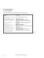
8.1 Error messages ....................................................................................................68
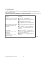
8.2 Fault diagnostics...................................................................................................69
8.3 Service..................................................................................................................70
8.4 Replacement parts................................................................................................74
8.5 After sales service ................................................................................................74
EFT/ Burst Generator PEFT Junior
9. Shutdown and storage
75
9.1 Daily shutdown..................................................................................................... 75
9.2 Storage for long periods....................................................................................... 75
10. Packaging and Transport
76
10.1 Packaging .......................................................................................................... 76
10.2 Transport ........................................................................................................... 76
11. Disposal
77
11.1 Disassembly information .................................................................................... 77
11.2 Recyclable components ..................................................................................... 77
11.3 Non-recyclable components............................................................................... 77
12. Accessories and options
78
12.1 Accessories........................................................................................................ 78
12.2 Options .............................................................................................................. 78
13. Corrections and additions
EFT/ Burst Generator PEFT Junior
79
1. Description
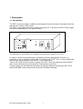
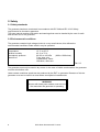
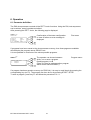
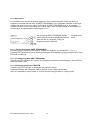
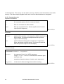
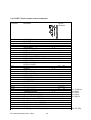
1.1 Introduction
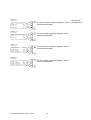
The PEFT Junior test system, enables electromagnetic immunity testing in accordance with the
standard IEC 1000-4-4 (IEC 801-4).
The built in single phase mains filter enables coupling of EFT / Burst into the EUT mains supply
with minimum disturbance to the general mains.
HAEFELY
HAEFELY
CONTROL UNIT
PEFT.1
Fig. 1.1
The equipment is controlled by an integrated microprocessor control unit ( P90 ).
In order to conduct three phase tests in accordance with the standard IEC 1000-4-4, it is
necessary to use an external coupling filter. For example the FP-EFT 32.1 is a three phase filter
that can be controlled directly from the PEFT Junior mainframe.
Tests in IEC 1000-4-4 which require coupling of the EFT / Burst into data and communication
lines, can be achieved using the capacitive coupling clamp type IP4A.
The test system can be made fully automatic, by using the optional interface type RC 730 for
RS232 and IEEE communication with the WinPATS software package.
EFT/ Burst Generator PEFT Junior
1
1.2 Technical data
The PEFT Junior, has the following technical characteristics:
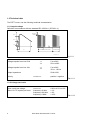
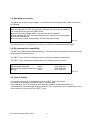
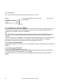
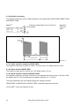
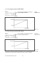
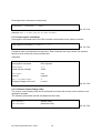
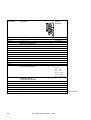
1.2.1 Impulse shape
Definition in accordance with the standard IEC 1000-4-4 ( IEC 801-4 )
V
V
Vnominal
Delta V
90 %
50 %
10 %
t
ta
t
SPIKE FREQ.
tb
BURST FREQ:
BURST DUR.
PEFTMES1.PIC
Fig.1.2.1
Voltage impulse form into 50 Ω
ta
tb
5 ns ±30%
50 ns ±30%
Voltage impulse form into 1kΩ
ta
tb
5 ns ±30%
35 ns...150 ns
Output impedance
Polarity
50 Ω ±20%
POLARITY
positive / negative
Tab.1.2.1
1.2.2 Voltage test levels
Open circuit test voltage
delta V for 75 impules per burst
2
Vnominal
frequency=10 kHz
frequency=100 kHz
frequency=1 MHz
0.22 to 4.5 kV ±10%
≤ 1%
≤ 2%
≤ 10%
EFT/ Burst Generator PEFT Junior
Tab.1.2.2
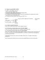
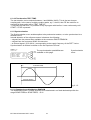
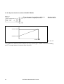
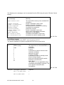
1.2.3 Operating frequencies
Impulse frequency
(limited as a function of test
voltage, see Fig 1.2.3a )
SPIKE FREQ
1 Hz to 1 MHz
±2% for F≤100 kHz
±20% for F≤1MHz
Burst duration
BURST DUR
0.01 to 20 ms ±2%
Burst frequency
BURST FREQ
1 to 400 Hz ±2%
Impulses / second
max. 600
Impulses / burst
SPIKE/BURST
max. 150
Tab.1.2.3
Diagram of limitations
V
4.5kV
0.5kV
0.25kV
1Hz
500kHz
1MHz
F
Fig.1.2.3a
EFT/ Burst Generator PEFT Junior
3
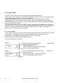
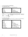
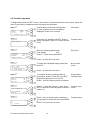
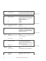
1.2.4 Coupling modes
The EFT / burst can be delivered as follows.
Coupling into control lines using
the capacitive coupling clamp
To HV-OUT
Direct output to SHV
connector
Coupling into single phase mains To-LINE 1PHASE
Output coupled to
integrated single
phase filter
Coupling into three phase mains
Direct output to SHV
connector,
with control of the
external three phase
filter
To-LINE 3PHASE
Tab.1.2.4
1.2.5 Single phase integrated filter
Maximum operating voltage
Ueff
250 V
Maximum operational current
DC
max.10 A
50 Hz max. 16 A
400 Hz max. 9 A
Bandwidth
1 to 100 MHz
Coupling attenuation
< 2 dB
Asymetric filter attenuation
> 20 dB
Tab. 1.2.5
1.2.6 Connections
High voltage output
to coaxial connector type SHV
Mains input to integrated filter
connector type IEC 320 250 V / 16 A
Mains output from integrated filter Euro (Schuko) 250 V / 16 A
Tab. 1.2.6
4
EFT/ Burst Generator PEFT Junior
1.2.7 Control
Synchronisation with mains
162/3,40, 50, 60 ou 400 Hz
Impulse trigger
Manual or automatic
Oscilloscope trigger
Signal + 15 V on output BNC
Safety
Software: via safety circuit
External 3 phase coupling filter
( option )
The connection "P90 extension" enables
control of an external coupling filter.
Test report
By connecting a printer to the serial output.
Remote control ( option )
Type RC730 interface for RS232 and IEEE.
Tab. 1.2.7
EFT/ Burst Generator PEFT Junior
5
1.3 Dimensions
The generator is built into a 19 " case 3 " high, its dimensions are:
Case (internal)
Housing
Weight
19", 3", 480 mm
520 x 166 x 500 mm
18 kg
Tab 1.3
Attention
For optimal ventilation and access to the rear
panel connectors, it is recommended that a
space of approximately 25 cm be left around
the generator
1.4 Electrical connections
The generator mains input is on the back panel.
Mains requirements are:
Single phase voltage
Nominal power
230 V ( 50 Hz )
115 V ( 60 Hz )
120 VA
± 10 %
± 10 %
( 230 V, 50 Hz )
( 115 V, 60 Hz )
Tab. 1.4
Mains voltage selection is made using the manual switch on the rear panel.
Connection to the mains is made using a 10 A cable fitted with the relevant plug:
Europe ( CEE-7/VII )
Great Britain ( BS-1363 )
Switzerland ( SEV Type 12 )
USA ( NEMA5-15P )
6
EFT/ Burst Generator PEFT Junior
1.5 Lexicon
An aide memoire for the electrotechnical vocabulary used in the standard IEC 50 (161)
EUT
EMC
EFT/B
Equipment Under Test
Electro Magnetic Compatibility
Electrical Fast Transient / Burst
Coupling network
Electrical network for the purpose of
transferring energy from one circuit to
another
Electrical network for the purpose of filtering
signals
Electrical circuit (single-threephase)
incorporating coupling and decoupling
networks
High Voltage
Decoupling network
Coupling filter
(single-threephase)
HV
Tab 1.5
EFT/ Burst Generator PEFT Junior
7
2. Safety
2.1 Safety standards
The generator has been constructed in accordance with IEC 348 and IEC 1010: Safety
requirements for electronic apparatus.
This user manual contains information and warnings that must be heeded by the user for safe
and efficient use of the generator.
2.2 Environmental conditions
The generator contains high voltage circuits in a very small volume, this defines the
environmental conditions under which it may be operated.
Temperature
Relative humidity
Atmospheric pressure
Absence of
15 °C to 35 °C
45 % to 75 %
86 kPa to 106 kPa
Frost, dew, rain,
condensation, water
infiltration, direct sun
(860 to 1060 mbar)
Tab. 2.2
The generator must only be used in dry rooms. In the case of visible condensation, the generator
must be dried before use.
Under certain conditions sparks can be produced by the EUT or generator. Because of this the
generator must not be used in an area where an explosion hazard exists.
WARNING
Persons with heart pace makers must not be in
the area when the generator is operating
8
EFT/ Burst Generator PEFT Junior
2.3 Operating precautions
The generator produces high volatges, it is essential that the following basic safety instructions
be followed:
Do not approach the EUT during testing. Accesss to the EUT during operation
can be prevented by use of the safety circuit.
Never touch high voltage cables or connections during operation.
When handling the EUT, the high voltage and any supply to the coupling filter
must first be switched off.
For any service inside the generator, first disconnect the mains.
Tab. 2.3
For safety reasons, the generator must only be connected to an earthed mains supply.
2.4 Electromagnetic compatibility
The EUT may radiate electromagnetic energy. The local rules and regulations must be observed
with regard to this stray energy.
The PEFT Junior should not be placed close to sensitive measuring instruments.
The PEFT Junior satisfies the requirements of the following immunity tests:
Electrostatic discharge
level 4
Electric fast transients and burst level 3
Surge
level 3
(IEC 1000-4-2)
(IEC 1000-4-4)
(IEC 1000-4-5)
Fig. 2.4
2.5 Limit of liability
This operator manual is an integrated part of the PEFT Junior test system.
The safety and operating instructions must be complied with.
Emile Haefely & CO LTD. and all its sales partners refuse to accept responsibility for
consequential or direct damage caused to persons and / or goods due to non-observance of the
user manual or incorrect use of the PEFT Junior.
EFT/ Burst Generator PEFT Junior
9
3. Technical overview
3.1 Construction
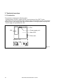
The generator comprises the following parts:
- microprocessor unit P90, contains all the control elements of the PEFT Junior.
- Main PCB, here are mounted the high voltage supply and regulation circuits, the impulse
forming circuits, high voltage switch and most elements of the single phase coupling filter.
- Power supply unit, generates 24 V DC.
Fan
Power supply unit
P90
Main PCB
Filter coils
HAEFELY
HAEFELY
CONTROL UNIT
PEFT.1
Fig. 3.1
10
EFT/ Burst Generator PEFT Junior
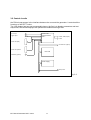
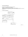
3.2 Control circuits
the P90 microprocessor is the interface between the user and the generator. It controls all the
functions of the PEFT Junior.
The LCD display has two user accesseable layers, the first is to display parameters and test
sequences, the second displays the operational conditions during a test.
Syncro Input
Trigger output
Control unit
microprocessor
P90
RS232 / IEEE (Option)
Printer
Control unit display
P90 Extension (Option)
Control unit keyboard
Main PCB
EUT failed ( option )
Power supply
Safety circuit
Fig. 3.2
EFT/ Burst Generator PEFT Junior
11
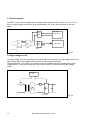
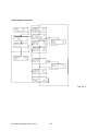
3.3 Power supplies
the PEFT Junior must be supplied from a single phase supply of either 230 V / 50 Hz or 115 V /
60 Hz. Supply voltage changeover is accomplished by use of the manual switch on the rear
panel.
HV supply
Manual
(Main PCB)
switch
L
Power
115/230
Supply
N
Main PCB
+24 V
Main switch
Filter
Mains voltage
control
PE
Fig. 3.3
3.4 High voltage circuit
The high voltage circuit is mounted on the main PCB and comprises, the high voltage source, an
earth safety relay, high voltage switch and the energy storage capacitors.
These capacitors, 11 in series, are a charge reservoir loaded from and regulated by the high
voltage source. They provide energy for the impulse, which is released by the high voltage
switch.
Generator
control
Earth relay
Fig. 3.4
12
EFT/ Burst Generator PEFT Junior
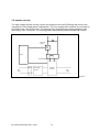
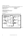
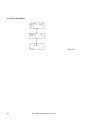
3.5 Impulse circuits
The high voltage impulse forming circuits are located on the main PCB along with most of the
components of the single phase coupling filter. The only coupling filter elements not mounted on
the PCB are the 140 uH filter coils. The coupling filter comprises the coupling capacitors and
decoupling ( filter ) elements. The coupling path is automatically switched under P90 control.
Electronic
switch
control
Waveshape circuit
Line
input
Decoupling
network
Coupling
network
Line
output
Fig. 3.5
EFT/ Burst Generator PEFT Junior
13
4. Control elements
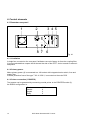
4.1 Generator rear panel
1
3 45
2
POWER
HAEFELY
I/O PROTECTION
LINE INPUT
SAFETY CIRCUIT
REMOTE CONTROL 730
8 7 6
Fig. 4.1
4.1.1 Ventilation
A single fan, mounted on the rear panel, facilitates removal of warm air from the coupling filter.
It is recommended that a space be left around the side of the PEFT Junior to assist in warm air
dissipation
4.1.2 Primary power.
Mains primary power (2) is connected to a 10A socket with integrated mains switch, fuse and
supply filter.
A mains protection fuse of the type T 0.2 A / 250 V, is mounted on the main PCB.
4.1.3 Printer connection ( PRINTER)
Test reports can be generated by connecting a serial printer to the PRINTER socket (3).
the RS232 configuration is:
Baud rate
Databit
Stopbit
Parity
14
9600
8
2
0
EFT/ Burst Generator PEFT Junior
The following pins are used:
Pin 2
Pin 3
Pin 20
Pin 7
Pin 18
Pin 1
RxD
TxD
DTR
GND
+5V
Chassis
4.1.4 Interface IEEE/GPIB (Option )
This interface is part of the RC 730 remote control module.
For more information refer to the RC 730 user manual.
4.1.5 Interface RS 232.(Option)
This interface is part of the RC 730 remote control module.
For more information refer to the RC 730 user manual.
4.1.6 External coupling filter control - P90 EXTENSION (option)
The P90 EXTENSION connection enables control of an external three phase coupling filter type
FP-EFT 32.1 directly from the PEFT Junior test system.
As for the single phase integrated filter, the generator controls automatically, the coupling mode
and synchronisation source.
Further information is provided in the FP-EFT 32.1 user manual.
4.1.7 Safety circuit ( SAFETY CIRCUIT )
The safety circuit connector enables the user to construct a safety loop around the test system
and / or EUT.
Detection of this circuit condition is under software control.
When activated ( open ) the software disables the high voltage and a failure message is
displayed.
The short circuit safety plug delivered with the generator can be adapted to suit the users
requirements.
4.1.8 Mains voltage selection ( Line input )
The mains voltage selector, can be switched using a screwdriver or small coin. The switch
function is to enable selection to either 110 V or 220 V in accordance with the laboratory supply.
EFT/ Burst Generator PEFT Junior
15
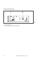
4.2 Generator front panel
1
2
HAEFELY
HAEFELY
CONTROL UNIT
PEFT.1
Fig. 4.2
1 - Control unit P90.1
2 - High voltage impulse output connections
16
EFT/ Burst Generator PEFT Junior
4.2.1 Control unit P90
The PEFT Junior is controlled by a microprocessor control unit. The processor ( 8085 ), monitors
generator functions, reads the keypad, sends information to the display, controls test parameters
and facilitates the storing and recall of test sequences. The user enters all commands from the
front panel. Main components of the front panel are an LCD display (1) a numerical keypad (11)
and the function keys (9).
HAEFELY P90.1
CONTROL UNIT
8
F1
F2
1
9
F3
10
F4
2
3
4
START / STOP
POWER
ON / OFF
SAFETY
SYNC
IN
HV / LINE ON
TRIGGER
OUT
5
6
7
8
9
4
5
6
1
2
3
.
0
UP
DWN
11
BSP
ENT
7
Fig. 4.2.1
4.2.1.1 Liquid crystal display (1)
PEFT Junior status information, test parameters and test sequences are available on this display.
The display is four lines of twenty characters each. Each line relates to a function key (9). The
last digit on the first and fourth lines is reserved for the symbol → which indicates more menu
pages are available either above or below.the current position. These pages can be accessed
using the keys (8) and (10).
EFT/ Burst Generator PEFT Junior
17
4.2.1.2 Safety circuit indications SAFETY (2)
The state of the safety circuit is indicated by the SAFETY lamps, green indicating that the safety
circuit is open and red that the circuit is closed. The function of the safety circuit has already been
described in section 4.1.12.
A green lamp, open safety circuit, means that the high voltage is disabled and it is safe to work
with the EUT.
A red lamp, safety circuit closed, means that the high voltage can be enabled.
Exercise caution !
4.2.1.3 START / STOP key (3)
The START / STOP key activates the high voltage and commences the test sequence. The lamp
HV / LINE ON (4) illuminates, indicating the high voltage on state. Pressing START / STOP when
the test is running will disable the high voltage.
During a test sequence, START / STOP enables a program to be stopped or continued
depending on the generator condition. For more information refer to section 6.
4.2.1.4 HV / LINE ON indication (4)
If this lamp is illuminated, the high voltage is on and may be present at the high voltage output or
on the EUT.
4.2.1.5 POWER ON / OFF switch (5)
Primary power is made available to the internal circuits when this switch is depressed.
A green lamp in the switch indicates that the generator is under power. The entry menu should
be displayed on the front panel.
For safety reasons, only a low level voltage is available on this switch.
4.2.1.6 Synchronisation input SYNC IN (6)
The BNC SYNC IN enables connection of an external AC signal having the following parameters:
Voltage
Frequency
24-264 Veff
162/3-400 Hz
Tab. 4.2.1.6
This signal is used to synchronise the PEFT Junior output when operated in conjunction with a
coupling filter.
4.2.1.7 Oscilloscope trigger output TRIGGER OUT (7)
Available at the TRIGGER OUT socket is a square wave of + 15 V amplitude with the negative
edge synchronised to each burst.
4.2.1.8 Menu previous page (8)
The ↑ key enables scrolling backwards, only if the → character is available at the end of the first
line.
18
EFT/ Burst Generator PEFT Junior
4.2.1.9 Function keys F1 to F4 (9)
The keys F1 to F4 activate user access to the functions shown on the respective lines of the
display. After pressing a key, the cursor is visible, and the parameter can be changed. After
entering the new value, press the function key again and the parameter is entered. Parameter
values consist of both alphabetic and numerical characters.
4.2.1.10 Menu next page (10)
The key ↓ enables scrolling forwards, only if the → character is available at the end of the fourth
line.
4.2.1.11 Numerical keypad (11)
The numerical keypad is used to enter numerical values or change predefined values.
The keys 0 to 9 are used to change a parameters numerical value. When a parameter has been
selected with one of the function keys, the cursor is placed on the last digit of the parameter
value. New data entered from the keypad automatically overwrites the previous value. When a
change is confirmed with the ENT key, the internal memory replaces the old data with the new
value.
The cursor is no longer visible.
. is the numerical comma.
Press ENT to place the current parameter value in memory.
The BSP key shifts the cursor by one digit to the left. the key is useful for corrections.
The UP key increments a numerical value or changes the value of a pre defined alphanumeric
character.
The DWN key decrements a numerical value or changes the value of a pre defined alphanumeric
character.
EFT/ Burst Generator PEFT Junior
19
4.2.2 High voltage impulse output connections
COUPLING
OUTPUT
N
PE
INPUT
L
ON/OFF
HV OUTPUT
SPIKE TRIGGER
OUTPUT
1
2
3
4
5
6
7
Fig. 4.2.2
4.2.2.1 EUT mains supply
The single phase mains input connector ( 7 ) is on the right hand side of the front panel, and the
EUT connection ( 4 ) is in the centre.
Mains input is connected using a 16 A cable. The EUT connection is via a Schuko type output
cable
After a test using EUT mains power has terminated, it is recommended that the mains be
switched OFF using the INPUT ON/OFF switch (5).
4.2.2.2 Coupling paths
Coupling paths are indicated by the lamps L, N, and PE ( 3 ).
The generator can perform all the coupling paths required by the standard IEC 1000-4-4.
4.2.2.3 EUT mains protection
There is no EUT mains protection. Protection of EUT circuits is the responsibility of the user.
20
EFT/ Burst Generator PEFT Junior
4.2.2.4 High voltage burst output
The lamps 1 and 3 indicate the selected burst output path. The following table shows the state of
the high voltage output connector ( 2 ) for different coupling modes.
Direct output:
"TO HV-OUT"
This mode is used for:
- coupling into signal line
- verification of the pulse form
Output to single phase coupling filter
"TO LINE 1PHASE"
Output is inactive
Output to three phase coupling filter
"TO LINE 3PHASE"
This mode is only used for external
coupling filters
Tab. 4.2.2.4
The high voltage connector is of a type SHV.
4.2.2.5 Ground connection
The ground connection ( 6 ), is a reference point to be used when the PEFT Junior is operated in
conjunction with an FP-EFT 32.1, for three phase coupling. It is recommended that a braided
cable or copper band be used for this connection.
EFT/ Burst Generator PEFT Junior
21
4.3 Control modes
The PEFT Junior can be used in several modes for different applications.
Local control is often sufficient in a laboratory application where the operator can directly adjust
the test parameters for different tests of short duration.
In quality laboratories however, it is often necessary to make endurance tests. For this
application the PEFT Junior can be used in remote control mode. Remote operation has the
advantage that several tests can be run sequentially and the test results can be printed directly
into a user defined test report.
In ECM test laboratories, where the PEFT Junior is used with other test equipment to conduct
tests on an EUT, it is important to remember that switching between an EFT / burst source and a
surge source is sometimes important without interrupting the EUT supply. In this case, the
remote control mode is the only one possible.
4.3.1 Local control
In local mode, the user has to set the test parameters and store them as programs in the control
unit memory. It is possible to store up to eleven programs. Each program can be run
independantly, be looped with other programs or be run continuously.
This is the normal mode of operation after power on.
For more details refer to section 6.
HAEFELY P90.1
CONTROL UNIT
WRITE-RUN-SAVE
1
PROG-A
2
PROG-B
3
F1
--> →
→
HAEFELY P90.1
CONTROL UNIT
SAVE PROGRAM IN
1→
CHANGE PROGRAM -->
NEXT PROGRAM
2
PRINTER
OFF→
F2
F3
F4
F1
F2
F3
The operator can choose between:
Write, run or save a program
Recall program A or B
(Place 3 is free for storing another program
which will be named PROG-C).
The current parameters can be stored in
Store menu
memory location 1.
After running program 1, the next program 2
will be automatically recalled and run.
F4
22
Program menu
EFT/ Burst Generator PEFT Junior
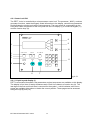
4.3.2 Remote control
In remote control mode, the generator can be operated through the communication interface type
RC 730 in both RS232 and IEEE modes.
Control using the software P90U allows programs to be transfered in both directions between the
PEFT Junior and a PC.
It is also possible to control the generator from a PC using the WinPATS software running under
windows. This has the advantage that the parameters are fully accessable from the PC.
Before entering the remote operating mode, the interface has to be correctly configured.
Interface parameters are accessed by holding down any key on the keypad, while simultaneously
powering the PEFT Junior on. For more details, see section 6.4.
HAEFELY P90.1
CONTROL UNIT
system service menu
INIT SYSTEM
->
REM.CONTROL SETUP ->
CONTINUE
->
F1
F2
F3
This screen apears after pressing any key
and the power on switch together.
To modify the remote configuration, press
F3.
Service menu
Press F3 to select the transmission
parameters.
Interface menu
During the remote mode, this page is
displayed.
Remote control
menu
F4
HAEFELY P90.1
CONTROL UNIT
remote control
setup menu
INTERFACE RS-232C
LOAD SETUP
-->
F1
F2
F3
F4
HAEFELY P90.1
CONTROL UNIT
system
PEFT
module
Junior
RS-232C CONTROLLED
F1
F2
F3
F4
EFT/ Burst Generator PEFT Junior
23
5. Test set up
5.1 Instruction for set up
Before using the PEFT Junior, this user manual should be read carefully.
5.2 Operating personnel
Operating the PEFT Junior without having read the user instructions, can expose the operator to
potential dangers.
It is recommended that only trained personnel be allowed to operate the PEFT Junior.
WARNING
Persons with heart pacemakers must not be
in the area when the PEFT Junior is
operating.
Remember:
the presence of high voltages is a potential danger even to trained personnel.
5.3 Initial operation
Before initial operation, please check the following points:
5.3.1 Optical control
During transport, all material is subjected to vibrations and mechanical shocks. Before initial
operation check for mechanical damage. All modules and blank plates should be fitted so that
they make good contact with the chassis.
5.3.2 Mains power
Check the mains power available in your laboratory is compatible with the PEFT Junior.
The mains voltages and frequencies are given in section 1.4
24
EFT/ Burst Generator PEFT Junior
5.4 Installation in accordance with IEC 1000-4-4
The EFT / burst generator PEFT Junior is designed to meet the requirements of the standard IEC
1000-4-4.
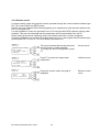
5.4.1 Installation for single phase testing
The following installation is described in the standard.
EFT/B Generator
Cc=33nF
Cc
Cc
Cc
L
EUT
N
PE
Reference Ground
connector
Fig. 5.4.1.a
Without further accessories, a PEFT Junior enables testing of levels 1 to 5.
PEFT Junior
HAEFELY
HAEFELY
CONTROL UNIT
Fig. 5.4.1.b
EFT/ Burst Generator PEFT Junior
25
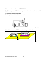
5.4.2 Installation for three phase testing
The following installation is described in the standard.
EFT/B Generator
Cc=33nF
Cc Cc Cc Cc Cc
L1
L2
EUT
L3
N
PE
Reference Ground
connector
Fig. 5.4.2.a
To comply with this tests requirements, it is necessary to use a three phase coupling filter type
FP-EFT 32.1. This filter has the same advantages as the single phase integrated filter, that is
automatic control of the coupling paths from the PEFT Junior menu.
A system comprising a PEFT Junior and a filter FP-EFT 32.1 enables testing to all levels as for
the single phase filter.
EUT
PEFT Junior
HAEFELY
HAEFELY
CONTROL UNIT
PEFT.1
FP-EFT 32.1
HAEFELY
FP-EF T32.1
FILTER
OPEN
BY-PASS
COUPLING
INPUT
L1
INPUT
L2
L3
N
DIRECT OUTPUT
POWER
ON/OFF
PE
LINE INPUT
LINE OUTPUT
SAFETY SWITCH
32A 690V
GND
Fig. 5.4.2.b
26
EFT/ Burst Generator PEFT Junior
5.4.3 Installation for coupling into control lines.
To couple into data lines as described in the standard, the capacitive coupling clamp type IP4A is
neccessary.
EUT
EUT
PEFT Junior
H AEFELY
H AEF ELY
C ONTR OL U N I T
P E FT.1
IP4A
Fig. 5.4.3
EFT/ Burst Generator PEFT Junior
27
5.5 Other test system possibilities
It is possible to include the PEFT Junior in many different test configurations.
The following examples illustrate some of the possibilities.
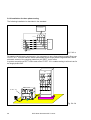
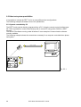
5.5.1 System controlled by PC
The PEFT Junior can be directly programed from a PC. Using the remote control interface type
RC 730 it is possible to communicate directly with a remote PC using either RS232 or IEEE
formats.
The WinPATS software running under Windows 3 is an example of communication software
curently available.
The following example shows the connections necessary for a computer controlled three phase
test system.
WinPATS
RS 232 & IEEE
HAEFELY
HAEFELY
CONTROL UNIT
PEFT.1
HAEFELY
FP -E FT32. 1
FILTER
OPEN
BY-PASS
INPUT
COUPLING
L1
INPUT
L2
L3
DIRECT OUTPUT
N
POWER
ON/OFF
PE
LINE INPUT
L1
LINE OUTPUT
L2
N
L3
PE
N
SAFETY SWITCH
32A 690V
GND
L1
PE
L2
L3
Fig. 5.5.1
28
EFT/ Burst Generator PEFT Junior
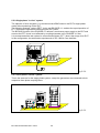
5.5.2 Single phase "on line" system
The objective of such a system, is to conduct several EMC tests on the EUT's single phase
mains without powering off the EUT.
The following example, using a PEFT Junior and PSURGE 4.1, enables the superimposition of
EFT / burst and surge without interrupting the EUT power.
The BYPASS function of the PSURGE 4.1 delivers a continuous power supply to the EUT and
ensures the EFT / burst is not affected by coupling elements in the PSURGE 4.1 filter.
It is recommended the test system be connected as follows, EFT / burst, then surge, then EUT.
In this configuration, the attenuation requirements of IEC 1000-4-5 are satisfied.
HAEFELY
HAEFELY
CONTROL UNIT
PPD.1
HAEFELY
PSURGE 4.1
OUTPUT
FILTER
OPEN
BY-PASS
L
PE
OUTPUT
N
INPUT
SAFETY SWITCH
16A 250V
HAEFELY
HAEFELY
CONTROL UNIT
PEFT.1
PEFT.1
Fig. 5.5.2
5.5.3 Three phase "on line" system
This is the same as for the single phase system, except the generators are connected to their
respective three phase coupling filters.
EUT
PSURGE 4.1
HAEFELY
HAEFELY
CONTROL UNIT
PPD.1
HAEFELY
PSURGE 4.1
OUTPUT
FILTER
OPEN
BY-PASS
L
OUTPUT
PE
N
INPUT
SAFETY SWITCH
16A 250V
PEFT Junior
HAEFELY
HAEFELY
CONTROL UNIT
PEFT.1
HAEFELY
FP-SURGE 32.1
FILTER
INPUT
OPEN
BY-PASS
HIGH
COUPLING
COMMON
18 uF
L1
9 uF
L2
10 R
L3
N
N
PE
L2
INPUT
L3
DIRECT OUTPUT
POWER
ON/OFF
HAEFELY
HAEFELY
F P -E FT 32. 1
FILTER
OPEN
BY-PASS
INPUT
COUPLING
L1
INPUT
L2
L3
N
DIRECT OUTPUT
POWER
ON/OFF
PE
LINE INPUT
LINE OUTPUT
LINE INPUT
SAFETY SWITCH
32A 690V
LINE OUTPUT
SAFETY SWITCH
GND
32A 690V
GND
Fig. 5.5.3
EFT/ Burst Generator PEFT Junior
29
5.5.4 EMC test system PATS
Using testers available from Haefely, it is possible to assemble a complete EMC test suite.
This is called PATS, is modular and allows testing to the following standards:
- EMC test, line interference;
IEC 1000-4-10,...
- EMC test, EFT / Burst;
IEC 1000-4-4
- EMC test, surge;
IEC 1000-4-5
In addition the system offers:
- Automatic verification of the test equipment
- Monitoring and detection of EUT failures
- Test report printout
- Storing test parameters
For more information please ask for a brochure from our sales department or local
representative.
Low Frequency
U
LFP6
Coupler
t
FP-SURGE 32.1
Verification
Master PC
Surge
WINPATS
PSURGE 4
U
t
Coupler
FP-EFT 32.1
EFT
PEFT
PEFT Junior
Printer
U
t
EUT
Fig. 5.5.4
30
EFT/ Burst Generator PEFT Junior
6. Operation
6.1 Parameter definition
The P90 microprocessor controls all the PEFT Junior functions. Using the P90, test sequences
can be written, saved, recalled and edited.
After powering the PEFT Junior, the following page is displayed.
HAEFELY P90.1
CONTROL UNIT
system
module
version
TO CONTINUE
F1
PEFT
Junior
1.6
PRESS F4
F2
Confirmation of the tester configuration.
In case of failure an error message is
displayed.
First menu
F3
F4
If programs have been saved to the microprocessor memory, then three pages are available
which display the program names PROG-A etc.
It is now possible to recall one of the eleven possible programs.
HAEFELY P90.1
CONTROL UNIT
WRITE-RUN-SAVE
1
PROG-A
2
PROG-B
3
F1
--> →
→
F2
F3
F4
The operator can choose between:
Write, run or save a program
Recall program A or B
(Place 3 is free for storing another program
which will be named PROG-C).
Program menu
If a program has been saved to memory (ex PROG-A), it is easy to recall simply by pressing the
corresponding key (ex F2). The program can then be run by pressing START / STOP.
To write a program, press key F1 and follow the procedure in 6.1.1.
EFT/ Burst Generator PEFT Junior
31
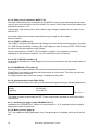
6.1.1 Input menu
The entry menu gives access to the first four parameters in a test.
HAEFELY P90.1
CONTROL UNIT
V-NOMINAL
.000KV →
POLARITY +/POS
TRIGGER
AUTO
→
CHANGE PROGRAM
F1
This page displays the first four test
parameters.
Entry menu
F2
F3
F4
6.1.1.1 Nominal test voltage V-NOMINAL
This parameter defines the output voltage level into an open circuit. Out of range parameters are
corrected by the program to the parameter limit. In the case of a voltage transition, the test
voltage will not exceed the value of V-NOMINAL.
NB:
- the test voltage can be changed manually during a test by pressing the UP/DWN keys. At the
end of the test, a message will be displayed, indicating that the voltage has been changed
manually.
- with the exception of V-NOMINAL, all the parameters have default values. This means that after
entering a value for the test voltage, it is possible to start a test immediately. The default
parameters correspond to the requirements of the standard IEC 1000-4-4.
6.1.1.2 Burst polarity POLARITY
Burst polarity is defined by this parameter. The possible options are POS for positve and NEG for
negative.
6.1.1.3 Burst trigger TRIGGER
The burst can be triggered one of two ways:
- manually ( MAN ): a burst sequence can be triggered by pressing any button on the keypad.
In this mode, BURST FREQ transition is not available.
- automatically ( AUTO ): a burst sequence is released at the frequency defined by BURST
FREQ.
32
EFT/ Burst Generator PEFT Junior
6.1.2 Burst output BURST OUTPUT
The PEFT Junior delivers the burst :
- direct to the high voltage output.
For example, when coupling into data lines using the IP4A.
- through the integrated single phase filter.
For coupling into the single phase supply of an EUT connected to the coupling filter output.
- through the external three phase filter.
For coupling into three phase mains using the FP-EFT 32.1.
HAEFELY P90.1
CONTROL UNIT
→
Burst output:
-TO HV-OUT
YES
-TO LINE 1PHASE ...
-TO LINE 3PHASE ... →
F1
Only one of the outputs can be selected
Burst output
menu
F2
F3
F4
6.1.2.1 Direct output TO HV-OUT
Press (F2), to select burst output to high voltage connector.
6.1.2.2 Coupling to single phase mains TO LINE 1PHASE
Press (F3), to select burst output to the integrated single phase filter.
6.1.2.3 Coupling to three phase mains TO LINE 3PHASE
Press (F4), to select burst output to high voltage connector. The three phase coupling filter FPEFT 32.1 is connected to the P90 EXTENSION, it is possible to select all the coupling paths
required by the standard.
This mode is exclusively for use with the Haefely FP-EFT 32.1 in single or three phase
applications.
After selecting the coupling mode, the next menu enables definition of the coupling path.
EFT/ Burst Generator PEFT Junior
33
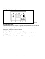
6.1.3 Coupling path options COUPLING PATH
6.1.3.1 Single phase coupling
The integrated coupling filter enables the following path selections:
Coupling path selection
- PATH L
- PATH N
- PATH PE
- PATH L+N
- PATH L+PE
- PATH N+PE
- PATH L+N+PE
HAEFELY P90.1
CONTROL UNIT
1ph coupling path: →
PATH L
ON
PATH N
OFF
PATH PE
OFF →
Coupling path selection
Phase 1
Neutral
Protection earth
Phase and neutral
Phase and Protection earth
neutral and Protection earth
All coupling paths simultaneously
F1
F2
By selecting all three modes to ON the paths Single phase
will be switched successively after test time coupling menu
has expired.
F3
F4
6.1.3.2 Three phase coupling
The external three phase coupling filter type FP-EFT 32.1 enables the following path selections
( all are referenced to GND):
Coupling path selection
- PATH L1
- PATH L2
- PATH L3
- PATH N
- PATH PE
- PATH L1+N
- PATH L1+PE
- PATH N+PE
- PATH L1+N+PE
- PATH L123
- PATH L123+N
- PATH L123+PE
- PATH L123+N+PE
34
Coupling path selection
Phase 1
Phase 2
Phase 3
Neutral
Protection earth
Phase 1 and neutre
Phase 1 and Protection earth
Neutral and Protection earth
Phase 1, neutral and Protection earth
Phase 1, 2 and 3
Phase 1, 2, 3 and neutral
Phase 1, 2, 3 and Protection earth
All coupling paths simultaneously
EFT/ Burst Generator PEFT Junior
HAEFELY P90.1
CONTROL UNIT
F1
3ph coupling path: →
PATH L1
ON
PATH L2
OFF
PATH L3
OFF →
HAEFELY P90.1
CONTROL UNIT
HAEFELY P90.1
CONTROL UNIT
L1+N
L1+PE
N+PE
L1+N+PE
L123
L123+N
L123+PE
L123+N+PE
F4
F2
F4
F2
The four modes if selected together, will be
executed sequentially
F3
F4
F1
OFF →
OFF
OFF
OFF →
The two modes if selected together, will be
executed sequentially
F3
F1
OFF →
OFF
OFF
OFF →
HAEFELY P90.1
CONTROL UNIT
PATH
PATH
PATH
PATH
F3
F1
3ph coupling path: →
PATH N
OFF
PATH PE
OFF
→
PATH
PATH
PATH
PATH
F2
Three phase
The three modes if selected together, will be coupling menu
executed sequentially
F2
The four modes if selected together, will be
executed sequentially
F3
F4
EFT/ Burst Generator PEFT Junior
35
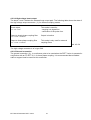
6.1.4 Repetition frequency
The repetition frequency menu, enables definition of the parameters SPIKE FREQ, BURST DUR
and BURST FREQ.
HAEFELY P90.1
CONTROL UNIT
F1
SPIKE FREQ. 5.00KHZ →
BURST DUR.
15.0ms
BURST FREQ.
3Hz
TEST TIME
300s →
Frequency parameters can be input from
this page.
F2
Repetition
frequency
menu
F3
F4
V
Vnominal
Delta V
t
SPIKE FREQ.
BURST FREQ:
BURST DUR.
Fig. 6.1.4
6.1.4.1 Spike repetition frequency SPIKE FREQ.
The repetition frequency of spikes in a burst. The unit is kHz. The default value is 5 kHz.
6.1.4.2 Burst duration BURST DUR.
The duration of each burst in units of mS. The default value is 15 ms.
6.1.4.3 Burst repetition frequency BURST FREQ.
The repetition frequency of bursts in units of Hz. the standard specifies a value of 300 ms ± 20%,
the default value of 3 Hz corresponds to a repetition frequency of 1 / 333 ms.
The three parameters are inter-related through the following formula:
SPIKE FREQ. x BURST DUR. x BURST FREQ. ≤ Max.Nb impulses per second.
For the PEFT Junior the maximum is 600.
36
EFT/ Burst Generator PEFT Junior
6.1.4.4 Test duration TEST TIME.
The test duration can be selected between 1 and 29999 s (8h33). This is the test time per
coupling path. In the case of multiple coupling paths, eg. L, then N, then PE the total time to
complete all three paths will be TEST TIME x 3.
To increase the test time, it is possible to loop a program with itself so it runs continuously until
START / STOP is pressed.
6.1.5 Synchronisation
The Synchronisation menu enables spikes to be produced at random, or to be synchronised to a
defined source.
Internal detection of the reference source is between the following:
- a signal from the external filter available at the connector P90 EXTENSION.
- a signal from the front panel SYNC IN connector.
- an internal signal ( 50 or 60 Hz ) corresponding to the supply frequency of the PEFT Junior.
Synchronisation is defined in relation to the first impulse of a burst.
HAEFELY P90.1
CONTROL UNIT
RANDOM SPIKES
BURST SYNCRO
SYNCRO FREQ.
SYNCRO ANGLE
The synchronisation possibilities are
available on this page.
F1
OFF →
OFF
50Hz
180° →
U
Synchronisation
menu
F2
F3
F4
SYNCRO FREQ.
t
SYNCRO ANGLE
Fig. 6.1.5
6.1.5.1 Random burst distribution RANDOM
The RANDOM function, enables impulses to be distributed in no fixed relationship within the
range SPIKE FREQ.to SPIKE FREQ. - 50 %.
EFT/ Burst Generator PEFT Junior
37
6.1.5.2 Burst synchronisation BURST SYNCRO.
This function is a software switch, burst synchronised to reference or not synchronised.
In the OFF condition, impulse distribution is determined by the parameters SPIKE FREQ.,
BURST DUR. and BURST FREQ.
In the ON condition, the first impulse of each burst is synchronised to the selected angle. Impulse
distribution is determined by the parameters SPIKE FREQ., BURST DUR, and the burst
repetition by BURST FREQ.
6.1.5.3 Frequency of synchronisation signal SYNCRO FREQ.
To synchronise with an external AC signal, the frequency must be defined. Possible frequencies
are 162/3 Hz, 40 Hz, 50 Hz, 60 Hz and 400 Hz.
6.1.5.4 Synchronisation to a phase angle SYNCRO ANGLE
The parameter SYNCRO ANGLE defines the angle in degrees, after the zero crossing point, to
which the impulses will be synchronised.
6.1.6 Transitions
The transition function allows a parameter to be varied during a test. It is posible to change the
test voltage, repetition frequency and synchronisation angle during a test.
HAEFELY P90.1
CONTROL UNIT
NO TRANSITION
VOLTAGE TRANS
FREQ.
TRANS
SYNCRO TRANS
38
F1
→
activ
.....
.....
→
.....
This page displays the functions which can
be varied during a test.
F2
F3
F4
EFT/ Burst Generator PEFT Junior
Transition
menu
6.1.6.1 Test voltage transition VOLTAGE TRANS.
HAEFELY P90.1
CONTROL UNIT
F1
voltage transition: →
V-START
.500KV
From this page it is possible to define the
voltage change parameters.
Voltage
transition menu
F2
F3
TRANS. TIME
20s→
F4
V-NOMINAL
V-START
TRANS. TIME
Fig. 6.1.6.1
6.1.6.2 Burst frequency transition FREQ. TRANS.
HAEFELY P90.1
CONTROL UNIT
F1
Freq. transition: →
F-START
1.00KHz
TRANS. TIME
20s
SPIKES/BURST
75 →
From this page it is possible to define the
frequency change parameters.
Frequency
transition menu
F2
F3
F4
SPIKE FREQ.
F-START
TRANS. TIME
Fig. 6.1.6.2
SPIKE/BURST defines the number of impulses per burst. It enables generation of a constant
energy ramp, each burst being composed of the same number of impulses.
EFT/ Burst Generator PEFT Junior
39
6.1.6.3 Synchronisation transition SYNCRO TRANS.
HAEFELY P90.1
CONTROL UNIT
F1
syncro transition: →
SYNCRO START
0°
TRANS. TIME
20s
→
From this page it is possible to define the
synchronisation change parameters.
Synchronisation
transition menu
F2
F3
F4
SYNCRO ANGLE
SYNCRO-START
TRANS. TIME
Fig. 6.1.6.3
The parameter SYNCRO START defines the ramp start angle in relation to the zero crossing
point. The angle starts to increment from this point.
40
EFT/ Burst Generator PEFT Junior
6.1.7 Save menu
It is possible to link several programs together to form a single program. When the end of a
program is reached and the value of NEXT PROGRAM is 0, the generator switches off the high
voltage and returns to the run menu. If the value of NEXT PROGRAM is not 0, but another
program number or the current program number again, then the high voltage is switched off the
next program is loaded and the new program is run.
HAEFELY P90.1
CONTROL UNIT
SAVE PROGRAM IN
NEXT PROGRAM
PRINTER
F1
11 →
0
OFF →
F2
F3
the parameter NEXT PROGRAM defines
which program will be automatically started
after the end of a program. Linking a
program to itself is possible.
Program save
menu
F4
6.1.7.1 Saving a program SAVE PROGRAM IN
Press the key F1 then enter the memory location the program is to be saved in ( 1 to 11 ).
Pressing ENT saves the currently defined parameters, automatically giving a program name from
PROG-A to PROG-K.
6.1.7.2 Linking programs NEXT PROGRAM
Press the key F3 and enter the value of the program to follow the current program. Press ENT to
save the chosen value.
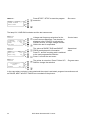
6.1.7.3 Selecting the printer PRINTER
Press the key F4 to activate or deactivate the printout function.
A printout contains the parameter settings as well as the measured test data.
Note: It is possible to select printer on or off even when the generator is running a test.
EFT/ Burst Generator PEFT Junior
41
The following is an example of a test printout:
HAEFELY EMC-TEST-SYSTEMS
BASEL/SWITZERLAND
DATE:..... TIME:.....
----------------------------------------------------------------------------SYSTEM: PEFT
MODULE:Junior
VERSION: 1.60
PROGRAM:
PROG-A
----------------------------------------------------------------------------VOLTAGE NOMINAL: 4.00KV
POLARITY: POS
SPIKE FREQUENCY: 5.00KHz
BURST DURATION : 15.0ms
BURST FREQUENCY:
3Hz
RANDOM SPIKES:
PHASE SYNCRO :
SYNCRO ANGLE :
VOLTAGE TRANSITION:
V-START:
TRANSITION TIME :
TEST TIME:
TRIGGER: AUTO
OFF
ON
90Deg/ 60 Hz
.500KV
60s
60Hz
======================================================================
1. BURST OUTPUT TO L
TEST TIME:
60s
Pause at 2.20KV
Pause at 2.61KV
2. BURST OUTPUT TO N
TEST TIME:
60s
Pause at 2.02KV
Pause at 2.54KV
3. BURST OUTPUT TO PE
TEST TIME:
31s
EUT failed
fail at 2.41KV
42
EFT/ Burst Generator PEFT Junior
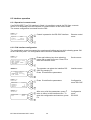
6.2 Function operation
To begin testing with the PEFT Junior, the minimum of parameters have to be entered. Never the
less it is necesary to understand how to program the generator.
HAEFELY P90.1
CONTROL UNIT
system
module
version
TO CONTINUE
F1
PEFT
Junior
1.6
PRESS F4
F2
Confirmation of the tester configuration.
In case of failure an error message is
displayed. Press F4 to continue.
First menu
From here it is posible to WRITE, RUN or
SAVE a program. Press F1 to enter the edit
menu.
Program menu
Enter the following parameters:
Test voltage
4 kV.
Press F1, enter 4 then press ENT.
Edit menu
F3
F4
HAEFELY P90.1
CONTROL UNIT
WRITE-RUN-SAVE
1
2
3
F1
-->→
→
F2
F3
F4
HAEFELY P90.1
CONTROL UNIT
F1
V-NOMINAL
4.00KV →
POLARITY +/POS
TRIGGER
AUTO
→
CHANGE PROGRAM
F2
F3
F4
Press ↓ to enter the next menu
HAEFELY P90.1
CONTROL UNIT
F1
→
Burst output:
-TO HV-OUT
...
-TO LINE 1PHASE YES
-TO LINE 3PHASE ... →
HAEFELY P90.1
CONTROL UNIT
HAEFELY P90.1
CONTROL UNIT
SAVE PROGRAM IN
NEXT PROGRAM
PRINTER
0
OFF →
HAEFELY P90.1
CONTROL UNIT
8
9
10
11
F4
F2
F3
→
Press ↓ to enter the next menu
To activate all three coupling modes in
succession, press F2, then UP, then ENT.
Repeat the operation for F3 and F4
Press ↓ until the following menu is reached
Single phase
coupling menu
F4
F2
Press F1, enter the number 11 then press
Program save
ENT to save the current program to memory menu
location 11.
F3
F4
F1
→
PROG-K
F3
F1
11 →
Burst output
menu
F2
F1
1ph coupling path: →
PATH L
ON
PATH N
ON
PATH PE
ON →
To select the integrated single phase filter
press F3.
F2
F3
Press ↓ twice to reach memory location 11.
Program menu
The program is saved with the name PROGK.
Press F4 to enter the run menu
F4
EFT/ Burst Generator PEFT Junior
43
HAEFELY P90.1
CONTROL UNIT
F1
PROG-K
loaded
CHANGE PROGRAM -->
Press START / STOP to start the program
execution
Run menu
F2
F3
PRESS START
F4
The lamp HV / LINE ON illuminates and the test commences.
HAEFELY P90.1
CONTROL UNIT
F1
V-NOMINAL
+4.0KV →
SPIKE FREQ. 5.00KHz
PAUSE
OFF
→
TST-TIME ..........
HAEFELY P90.1
CONTROL UNIT
PATH L
BURST DUR.
BURST FREQ.
F3
F4
F1
NEXT →
15ms
3Hz
→
HAEFELY P90.1
CONTROL UNIT
F2
F3
F4
F1
***PROGRAM***
PROG K
PRINTER
F2
→
OFF →
Voltage and frequency selections for the
current test are displayed. Test duration is
shown as a bar. Press F3 to activate the
PAUSE function, the high voltage remains
ON but the test is suspended.
Control menu
The values of BURST DUR and BURST
FREQ are displayed for information.
Press F1, and the coupling path is switched
to the next programmed selection.
Press ↓ to enter the next menu
Operational
menu
The printer is not active. Press F4 then UP /
DWN to change the selection
Program menu
F2
F3
F4
In the case where a printer is connected and the output is activated, program interventions such
as PAUSE, NEXT and EUT FAILED are recorded on the printout.
44
EFT/ Burst Generator PEFT Junior
6.3 Interface operation
6.3.1 Operation in remote mode
If an RS232/IEEE Type 730 interface is fitted, it is possible to control the P90 from a remote
device. It is necessary to set the interface for communication in the correct mode.
The remote configuration is entered from the P90.
HAEFELY P90.1
CONTROL UNIT
F1
system
PEFT
module
Junior
RS-232C CONTROLLED
Control is passed to the RS-232C interface.
Remote control
menu
F2
F3
F4
6.3.2 P90 interface configuration
The configuration menu is accessed, by pressing and holding any key while selecting power ON
at the P90 front panel. The configuration menu structure is detailed below:
HAEFELY P90.1
CONTROL UNIT
F1
system service menu
INIT SYSTEM
->
REM.CONTROL SETUP ->
CONTINUE
->
F2
Press and hold any key when selecting
power ON to reach this menu. Press F3 to
enter the interface menu.
Service menu
The operator can select the interface RS232C by pressing F3.
Press to define the parameters.
Interface menu
Press
Configuration
menu RS-232C
F3
F4
HAEFELY P90.1
CONTROL UNIT
F1
remote control
setup menu
INTERFACE RS-232C
LOAD SETUP
-->
F2
F3
F4
HAEFELY P90.1
CONTROL UNIT
BAUDRATE
DATABIT
STOPBIT
PARITY
F1
19200 →
8
2
NONE →
HAEFELY P90.1
CONTROL UNIT
PROTOCOLE
EOS
F2
F3
F4
F1
NONE→
CR+LF
to define the parameters.
F2
F3
After entry of all the parameters, press
twice to return to the interface menu. To
save this configuration and continue, press
F4.
F4
EFT/ Burst Generator PEFT Junior
45
Configuration
menu
RS-232C
HAEFELY P90.1
CONTROL UNIT
F1
remote control
setup menu
INTERFACE IEEE-488
LOAD SETUP
-->
The parameter menu for IEEE-488 is active.
Press to define the parameters.
Interface menu
After entry of all the parameters, press to
return to the interface menu. Press F4 to
save this configuration and continue
Configuration
menu IEEE-488
F2
F3
F4
HAEFELY P90.1
CONTROL UNIT
BUS ADDRESS
EOS
F1
12→
CR+LF
F2
F3
F4
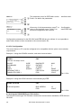
Configuration parameters for the RS-232C and IEEE-488 are pre defined. It is not possible to
select other values to those contained in the communication file.
6.3.3 PC Configuration
The control device or PC must be configured to be compatible with the sytem communication
requirements.
Example 1: Using the HP48SX controller, and serial communication.
HP48SX
From the "I/O setup" menu
IR/WIRE
ASCII/BINARY
BAUD
PARITY
CHEKSUM TYPE 3
TRANSLATE CODE 1
P90
WIRE
ASCII
9600
NONE 0
BAUDRATE
DATABIT
STOPBIT
PARITY
PROTOCOL
EOS
9600
8
1
NONE
XON/XOFF
CR+LF
Tab. 6.3.3a
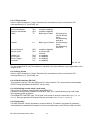
Example 2: Using the HP300 controller communicating by IEEE.
HP9000 series300
P90
HP-IB configuration
BUS ADRESS
EOS
12
CR+LF
Tab. 6.3.3b
6.3.4 Using the RS232/IEEE type 730 interface
The Remote-Control type 730 interface contains two communication standards, IEEE-488 and
RS-232C.
46
EFT/ Burst Generator PEFT Junior
6.3.4.1 Entry format
Given in ASCII characters (7 digit). Block and line terminations use the conventional CR
(Carriage Return), LF (LineFeed), etc.
Source Handshake
Acceptor Handshake
Talker:
SH1
AH1
T5
complete capability
complete capability
Basic type of talker
Listener:
L3
Basic type of listener
Service Request
Remote Local
SR1
RL2
Parallel Poll
Device clear
Device Trigger
Controller:
PP0
DC0
DT0
C0
complete capability
no control with
interlock
no capability
no capability
no capability
no capability
Series enquiry,
sounds always
faulty
De-addressing
with MLA
Sounds always
faulty
De-addressing
with MTA
Tab. 6.3.4.2
The bus address MTA ( My Talk Address ) and MLA ( My Listen Address ) are programable in the
range 0 to 30.
6.3.4.2 Entry format
Given in ASCII characters (7 digit). Block and line terminations use the conventional CR
(Carriage Return), LF (LineFeed), etc.
6.3.4.3 Serial Interface RS-232C
This interface uses the TxD and RxD lines for communication. For communication the hardware
RTS/CTS and the software XON/XOFF can be used.
6.3.4.4 Switching remote mode / local mode
Two modes of operation exist (LOCAL) and (REMOTE).
Equipment not fitted with a REMOTE CONTROL type 730, is automatically set to local mode
when primary power is applied.
If the REMOTE CONTROL type 730 is fitted, local mode is set by the command "GTL" (Go To
Local). Remote operation is selected with the command "REN" (Remote ENable).
6.3.5 Programing
The P90 controller, can be operated by a remote device. The data is composed of parameter
commands plus handshake information. Control commands sent to the P90 are held in a buffer
EFT/ Burst Generator PEFT Junior
47
of 128 characters. The memory can be used in two ways. The first uses 98 characters as a buffer
memory. The other accepts program blocks until an end of block character is recognised.
6.3.5.1 Command syntax
Seperation characters:
< >
No command (space) after the command header.
<;>
End of a command unit within a block.
<EOS>
End of a command block or blocks, signifies end of current
input (End Of Sequence).
Tab. 6.3.5.1a
Bit format:
Integer
positive whole numbers in the range 0 to 29999. transferred as
ASCII strings. The format corresponds with the input and
output of the P90 display
Real
positive decimal numbers.with a maximum of 6 significant
digits, transferred as ASCII strings. The format corresponds
with the input and output of the P90 display
Tab. 6.3.5.1b
Character strings:
set command=<header>< ><argument>
<header>
A sequence of from 2 to 4 ASCII characters
using.'A'..'Z';'a'..'z'. There is no differentiation between upper
and lower case
< >
separation character between <header> and <argument>.
<argument>
In the form of either an integer,real number or string.
Tab. 6.3.5.1c
48
EFT/ Burst Generator PEFT Junior
Entering several commands consequtively:
<command>{;<command>}...<EOS>
Tab. 6.3.5.1d
example: CHV 4.0;POL neg;PL on;PRT on<EOS>
6.3.5.2 Interrogation commands
Interrogation commands cause the P90 to transfer internal data to the system controller.
<interrogation command>=<header>{< >}<?>
Tab. 6.3.5.2a
A question mark is placed after the argument. Each command can only contain one question,
which must be at the end of the command line.
examples:
Interrogation command
P90 response
CACT?<EOS>
Actual impulse voltage?
4.0
4.0kV
POL?<EOS>
polarity?
NEG
negative
CHV 1.00;ERR?<EOS>
Charging voltage=1kV,error?
0
no error
Tab. 6.3.5.2b
6.3.5.3 Remote Control Debug utility
The remote control debug utility can be accessed from either the remote control module or the
application program
The following commands activate and deactivate this utility
DEB ON<EOS>
DEB OFF<EOS>
activate utility
deactivate utility
Tab. 6.3.5.3a
EFT/ Burst Generator PEFT Junior
49
Error messages:
Error number
Meaning
0
101
102
103
105
106
107
108
109
110
111
no error
Safety circuit open
No nominal voltage defined
Ramp start point is greater than the
maximum value
Ramp end point is greater than the
maximium value
No coupling path defined
SPIKE FREQ too large
BURST FREQ too large
Voltage range problem
Printer not ready
Nominal voltage too big
Nominal changed manually
201
202
EUT failure
General error
400
No external filter connected
104
Tab. 6.3.5.3b
50
EFT/ Burst Generator PEFT Junior
The following error messages, can be accessed from the P90 using the option "Remote Control
Debug":
Error Message
Meaning
input buffer ovfl
The input buffer memory has exceeded 100
characters
timeout exceeded in listen mode
Header exceeds 4 characters
the option part of a command is missing
command not recognised
parameter incorrect
timeout exceeded in talk mode
this is not an interrogation command
waiting for an interrogation
command not allowed in local mode
command only valid in standby mode
timeout occured
header >4 characters
option required
unknown header
invalid argument
timeout while talk
no query here
query expected
not valid in local
not valid while run
Tab. 6.3.5.3c
6.3.5.4 Error control
A list of options specific to the PEFT Junior is given in 6.3.5.5.
The options available for systems equiped with the P90 are given below.
ERR
(ERRor query)
Code
0
1
2
3
4
5
8
16
32
64
The response to a command ERR?, is
a number
Description
no error
command only valid in remote mode
unknown command
argument not valid
no query available
command only valid in standby mode
timeout during transmit
parity error during RS-232C transfer
overflow in receive buffer
other failure
The codes 1 to 5 are applicable to the
immediately preceeding command. The
error signal is reset after each
interrogation.
Tab. 6.3.5.4a
examples Interrogation command
CHV 1.25;ERR?<EOS>
CHV &%;ERR?<EOS>
EFT/ Burst Generator PEFT Junior
response
0
3
51
GTL
(Go To Local)
Terminate remote operation. Control is
only possible from the P90 front panel.
Tab. 6.3.5.4b
ID
(IDdentification)
The identification command (only as a
question) replies with the equipment
details in the form.
sssssss mmmmmmm vvvv
system
module
version
s
m
v
Tab. 6.3.5.4c
example
Interrogation command
ID?<EOS>
response
PEFT Nr.-- 1.60
A maximum 10 character name can be
assigned to the current program. in
query mode, the name of the current
program is returned.
NAME
Tab. 6.3.5.4d
example
PROG
controller
NAME Testprog.<EOS>
P90
a program is saved under the
name Testprog.
NAME?<EOS>
Testprog.
(store PROGram)
Saves the current program to a
memory location defined by the
argument. ( same as "Save Program in
XX" from local mode).
Integer (within the system range)
argument:
Tab. 6.3.5.4e
example
controller
PROG 5<EOS>
P90
save program in memory position 5
PRT
(PRinTer)
argument.
Enables or disables the printer.
ON, OFF
52
EFT/ Burst Generator PEFT Junior
Tab. 6.3.5.4f
example
REC
controller
PRT ON<EOS>
P90
printer active
PRT?<EOS>
ON
(RECall program)
Recalls a program designated by the
argument (function inverse of PROG).
Tab. 6.3.5.4g
REN
(Remote ENable)
the equipment is in remote mode,
controllable only from a remote device.
Tab. 6.3.5.4h
SP
(Serial Poll)
Reads the Status Bit . See the table,
corresponding to the possible values at
the end of this paragraph.
Tab. 6.3.5.4i
example
controller
SP?<EOS>
1. EUT Failed
2. Generator Error
3. Local Mode
4. Transmission Error
5. Command Error
6. Run Mode
7. Service Request
8. Triggering
STOP
(STOP)
P90
The character "!" corresponds to
00100001 in binary. The bit 1 indicates
EUT failed.
8 7 6 5 4 3 2 1
x x x x x x x 1
x x x x x x 1 x
x x x x x 1 x x
x x x x 1 x x x
x x x 1 x x x x
x x 1 x x x x x
x 1 x x x x x x
1 x x x x x x x
( x = 0 or 1 )
The bits identifying errors 4 and 5 can
be accessed by the command ERR?.
The function SRQ identified by 7 can
be accessed by the command SRQ.
The bit "EUT Failed" is only present
when the entry "EUT Failed" is active, It
is reset to zero by the following
operation.
Halts the program immediately
(function analogous to START/STOP in
local mode).
Tab. 6.3.5.4j
EFT/ Burst Generator PEFT Junior
53
STRT
(STaRT)
Runs the current program from
memory ( function analogous to
START/STOP in local mode ).
Tab. 6.3.5.4k
SRQ
(Service ReQuest)
argument
Activates or deactivates access to the
IEEE-488.
ON / OFF
Tab. 6.3.5.4l
STAT
(STATus)
Response
STBY
BUSY
READY
Check of the status bit (only
interrogation).
Description
Equipment in standby mode
Equipment in run mode (system
specific)
Equipment ready for run mode
Tab. 6.3.5.4m
example
controller
STAT?<EOS>
P90
STBY
Equipment in standby mode
TMO
(TiMe Out)
Defines the time limit for
communication.
Integer from 0 to 9
argument
Tab. 6.3.5.4n
54
EFT/ Burst Generator PEFT Junior
6.3.5.5 PEFT Junior remote control commands
Command
Description
CHV
POL
TRIG
V-NOMINAL (kV)
POLARITY
TRIGGER
x x
x x
x x
Real
POS, NEG
Auto, Man
HVOT
P3PH
PL
PN
PPE
PLN
PLPE
PNPE
PLNP
TO HV OUT
TO LINE 3PHASE
PATH L or PATH L1
PATH N
PATH PE
PATH L+N or PATH L1+N
PATH L+PE or PATH L1+PE
PATH N+PE
PATH L+N+PE or
PATH L1+N+PE
PATH L2
PATH L3
PATH L1+L2+L3
PATH L123+N
PATH L123+PE
PATH L123+N+PE
SPIKE FREQuency
BURST DURation
BURST FREQuency
RANDOM mode
Synchronisation function
SYNCRO ANGLE
SYNCRO FREQuency
Transition function
SYNCRO START
Syncro TRANSition TIME
Number SPIKE / BURST
Voltage transition VSTART
Voltage transition time
Frequency transition FSTART
Frequency transition VSTART
Frequency transition time
Next Program after Stop [0-11]
x
x
x
x
x
x
x
x
x
x
x
x
x
x
x
x
x
x
On,
On,
On,
On,
On,
On,
On,
On,
On,
x
x
x
x
x
x
x
x
x
x
x
x
x
x
x
x
x
x
x
x
x
x
x
x
x
x
x
x
x
x
x
x
x
x
x
x
x
x
x
x
x
x
x
x
x
x
On, Off
On, Off
On, Off
On, Off
On, Off
On, Off
Real
Real
Integer
On, Off
On, Off
Integer
F1...F5
Off,V,F,S
Integer
Integer
Integer
Real
Integer
Real
Integer
Real
Integer
PL2
PL3
PLA
PAN
PAPE
PANP
SFRE
BDUR
BFRE
RAN
SYNC
SDEG
SYNF
TRA
SSRT
STTM
SPB
VSRT
VTRT
FSRT
FTRT
TTME
NPRO
EFT/ Burst Generator PEFT Junior
Type of
parameter
55
Off
Off
Off
Off
Off
Off
Off
Off
Off
F1= 16 2/3 Hz
F2= 40 Hz
F3= 50 Hz
F4= 60 Hz
F5= 400 Hz
Tab. 6.3.5.5a
Command
Description
PRT
NAME
PROG
REC
ID
REN
GTL
DEB
SP
SRQ
ERR
EMSG
CACT
FACT
SACT
PACT
PRINTER
Program NAME
STORE Program
RECALL Programme
Identification, system, module...
Remote Enable
Go To Local
DEBUG mode
Serial Poll
Service Request
Error code
Error message
Actual Test voltage
Actual Spike frequency
Actual Syncro angle
Actual coupling path
STAT
Geneartor status
(STBY,BUSY,READY)
Actual configuration
Initiate trigger
STOP generator
START generator
Pause
Time Out
CONF
TR
STOP
STRT
PAUS
TMO
56
Type of
parameter
x
x
x
x
x x
x x
x
x
x
x
x
x x
x
x x
x
x
x
x
x
x
x
On, Off
String[10]
Integer
Integer
x
On, Off
x (Byte)
On, Off
x (Byte)
x (Integer)
x
x
x
x R1= L
R2= N
R3= PE
R4= L+N
R5= L+PE
R6= N+PE
R7= L+N+PE
x
String[20]
x x
x x
x x
x
x x x On, Off
Integer
x x x
EFT/ Burst Generator PEFT Junior
Tab. 6.3.5.5b
6.3.6 Program examples
Example 1: Controlling HP48SX serial interface.
The program initialises a voltage ramp, with no error reporting.
TEST1
<< "REN" PR1 "CHV 4" PR1 "POL NEG" PR1 "HVOT OFF" PR1 "PL ON" PR1 "TRA
V" PR1 "TTME 60" PR1 "VTRT 55" PRI "STRT" PR1 CLLCD "TEST VOLTAGE" 1
DISP 1 55 START "CACT?" PR1 0.5 WAIT 128 SRECV DROP SWAP DROP 'A' STO
'A' RCL 4 DISP "NEXT "STOP" PR1 "GTL" PR1 CLEAR>>
Explanations:
TEST1
"REN" PR1
"CHV 4" PR1
"POL NEG" PR1
"HVOT OFF" PR1
"L ON" PR1
"TRA V" PR1
"TTME 60" PR1
"VTRT 55" PR1
"STRT" PR1
program name
source control
test voltage = 4 KV
negative polarity
HV OUT deselected
coupling path L
voltage transition
test duration
voltage ramp duration
start the program
CLLCD
"TEST VOLTAGE" 1 DISP
1 55 START
control indication to HP48SX
comment
begin loop
"CACT?" PR1
request the actual charging voltage
0.5 WAIT
128 SRECV
DROP SWAP DROP
'A' STO 'A' RCL 4 DISP
NEXT
"STOP" PR1 "GTL" PR1
wait 0.5s
read 128 characters from the buffer
prepare display
store value of CACT then display at line 4
link programs
turn off the high voltage and return to local
mode
end
CLEAR
Tab. 6.3.6a
The programs are a quick demonstration of command principles. The parameters not definrd in
the examples are set to their default values.
EFT/ Burst Generator PEFT Junior
57
Example 2: Controlling HP9000 series 300 BASIC interface using IEEE
This program contains , voltage ramp error checking and a check for EUT failed.
10 DIM Name$ [30]
!
20
!
30
! Remote control and identification
40
!
50 OUTPUT 712;"REN"
! Remote enable
60 OUTPUT 712;"ID?"
! Identification
70 WAIT 0.5
! delay for communication
80 ENTER 712;Name$
! enter identification's name
90
!
100
! Prepare computer's display
110
!
120 PRINT TABXY(20,2)"HELLO USER ! MY NAME IS ";A$
130 PRINT TABXY(20,4)"DEMO PROGRAM FOR IEEE/PEFT CONTROL"
140 PRINT TABXY(35,8)"PARAMETERS"
!
150 PRINT TABXY(70,8)"ERRORS"
!
160
!
170
! Input parameters in PEFT/P90
180
!
190 CHVset=4
! Test voltage = 4kV
200 OUTPUT 712;"CHV ";CHVset
! Setting test voltage
210 OUTPUT 712;"CHV?"
! Control test voltage real
220 WAIT 0.5
! Delay for communication
230 ENTER 712;CHVreal
!
140 IF CHVreal<CHVset THEN ErrChv$="LIMIT VOLTAGE MAX"
! Test overlimit
150 IF CHVreal>chvset THEN ErrChv$="LIMIT VOLTAGE MIN"
! Test underlimit
160 ErrChv$="ok"
!
170 PRINT TABXY(35,10);"TEST VOLTAGE:";Chv,ErrChv$
! Display
180
!
190
!
200 OUTPUT 712;"POL NEG"
! Setting Polarity
210 OUTPUT 712;"POL?"
! Control Polarity
220 WAIT 0.5
! Delay for communication
230 ENTER 712;POL$
!
240 OUTPUT 712;"ERR?"
! Error test
250 WAIT 0.5
!
260 IF ERR=0 THEN ErrPOL$="OK" Else ErrPOL$=ERR;" see table"
270 PRINT TABXY(35,11);"POLARITY
:";POL$,ErrPOL$
! Display
280
!
290
!
300 TTMEset=500
! Test time = 500s
310 OUTPUT 712;"TTME ";TTMEset
! Setting test time
320 OUTPUT 712;"TTME?"
! Control test time real
330 WAIT 0.5
! Delay for communication
340 ENTER 712;TTMEreal
!
350 IF TTMEreal<TTMEset THEN ErrTTME$="LIMIT Test Time MAX"
! Test overlimit
360 IF TTMEreal>TTMEset THEN ErrTTME$="LIMIT Test Time MIN"
! Test unterlimit
370 ErrTTME$="ok"
!
380 PRINT TABXY(35,12);"Test Time
:";TTMEreal,ErrTTME$! Display
390
!
400
!
58
EFT/ Burst Generator PEFT Junior
410
420
430
440
450
460
470
480
OUTPUT 712;"TRA V"
! Setting voltage transition
OUTPUT 712;"TRA?"
! Control transition
WAIT 0.5
! Delay for communication
ENTER 712;TRA$
!
OUTPUT 712;"ERR?"
! Error test
WAIT 0.5
!
IF ERR=0 THEN ErrTRA$="OK" Else ErrTRA$=ERR;" see table"!
PRINT TABXY(35,13);"TRANSITION :";TRA$,ErrTRA$
! Display
490
!
500
!
510 VTRTset=100
! Transition time = 100s
520 OUTPUT 712;"VTRT ";VTRTset
! Setting Transition time
530 OUTPUT 712;"VTRT?"
! Control Trans.time real
540 WAIT 0.5
! Delay for communication
550 ENTER 712;VTRTreal
!
560 IF VTRTreal<VTRTset THEN ErrVTRT$="LIMIT TIME MAX"
! Test overlimit
570 IF VTRTreal>VTRTset THEN ErrVTRT$="LIMIT TIME MIN"
! Test unterlimit
580 ErrVTRT$="ok"
!
590 PRINT TABXY(35,14);"TRANS TIME :";VTRTreal,ErrVTRT$
! Display
600
!
610
!
620
!
1000 OUTPUT 712;"STRT"
! Test start
1010 OUTPUT 712;"STAT?"
! Status ?
1020 WAIT 0.5
! Delay for communication
1030 ENTER 712;STAT$
! Control status
1040 PRINT TABXY(35,16);"TEST STATUS:";STAT$
! Display
1050 IF STAT$="STBY" THEN GOTO beforeend
! End of test?
1060
!
1070
!
1080 OUTPUT 712;"SP?"
! Test serial poll
1090 ENTER 712;SP$
! Control serial poll
1100 IF BIT(NUM(SP$),1)=1 THEN stop ELSE continu
! Test EUT failed
1110 stop
!
1120 PRINT TABXY(35,18);"TEST ABORTED:";SPtest$
! Display
1130 OUTPUT 712;"GTL"
! return to local mode
1140 END IF
!
1150
!
1160
!
1170 continu
!
1180 OUTPUT 712;"CACT?
! Actual test voltage ?
1190 WAIT 0.5
! Delay for communication
1200 ENTER 712;CACT
! Control actual test voltage
1210 PRINT TABXY(10,10);"ACTUAL TEST VOLTAGE"
! Display
1220 PRINT TABXY(10,12);CACT;" kV"
! Display
1230
!
1240
!
1250 beforeend
!
1260 OUTPUT 712;"STOP"
! Savety in case of none stop
1270 OUTPUT 712;"GTL"
! Go to local mode
1500 END
!
EFT/ Burst Generator PEFT Junior
59
This program is a quick demonstration, using many commands. Parameters not defined in the
example are set to their default values.
6.3.7 Test programs
Verify numerical values from the program to be within the correct range ( the values are
automatically limited to their maximum and minimum ).
example:
180
190
200
210
220
230
140
!
! Test voltage = 4kV
! Setting test voltage
! Control test voltage real
! Delay for communication
!
VOLTAGE MAX"
! Test overlimit
150 IF CHVreal>chvset THEN ErrChv$="LIMIT VOLTAGE MIN"
! Test underlimit
160 ErrChv$="ok"
!
170 PRINT TABXY(35,10);"TEST VOLTAGE:";Chv,ErrChv$
! Display
CHVset=4
OUTPUT 712;"CHV ";CHVset
OUTPUT 712;"CHV?"
WAIT 0.5
ENTER 712;CHVreal
IF CHVreal<CHVset THEN ErrChv$="LIMIT
Verify the input of alphanumeric characters is accepted by the P90:
example:
400
410
420
430
440
450
460
470
!
OUTPUT 712;"TRA V"
! Setting voltage transition
OUTPUT 712;"TRA?"
! Control transition
WAIT 0.5
! Delay for communication
ENTER 712;TRA$
!
OUTPUT 712;"ERR?"
! Error test
WAIT 0.5
!
IF ERR=0 THEN ErrTRA$="OK" Else ErrTRA$=ERR;" see table"!
Never forget to stop the test:
example:
1260 OUTPUT 712;"STOP"
! Safety in case of none stop
Never forget to return to local mode:
example:
1270 OUTPUT 712;"GTL"
! Go to local mode
To select an output, do not forget, the HV OUT socket is active by default ( HVO=ON ) and all
other coupling paths are inactive. If coupling to a filter is required, first deactivate the path HV
OUT before entering a coupling path.
example:
60
EFT/ Burst Generator PEFT Junior
2410 OUTPUT 712;"HVOT OFF"
2420 OUTPUT 712;"PL ON"
EFT/ Burst Generator PEFT Junior
! Setting HV out off
! Setting coupling L
61
6.4 Functional diagrams
The PEFT Junior is initialised by switching on the mains.
Diagram 6.4.1 illustrates the menu possibilities.
Diagram 6.4.2 defines the procedure for programing a test sequence.
Functions which can be changed when the PEFT Junior is operating (RUN MODE ) are shown in
diagram 6.4.3.
6.4.1 Menu configuration
system service menu
RESET ALL PROGRAM ->
REM.CONTROL SETUP ->
CONTINUE
->
remote control
setup menu
INTERFACE RS-232C
LOAD SETUP
-->
BAUDRATE
DATABIT
STOPBIT
PARITY
→
19200
8
2
NONE→
PROTOCOL
EOS
NONE→
CR
remote control
setup menu
INTERFACE IEEE-488
LOAD SETUP
-->
BUS ADDRESS
EOS
12→
CR+LF
system
module
version
TO CONTINUE
PEFT
Junior
1.60
PRESS F4
Tab. 6.4.1
62
EFT/ Burst Generator PEFT Junior
6.4.2 Program functions
system
module
version
TO CONTINUE
PEFT
Junior
1.6
PRESS F4
WRITE-RUN-SAVE
1
PROG-A
2
PROG-B
3 (PROG-C)
-->→
V-NOMINAL
.000KV →
POLARITY +/POS
TRIGGER A/M
AUTO
→
CHANGE PROGRAM
→
YES
...
...→
surge output:
-TO HV-OUT
-TO-LINE 1PHASE
-TO-LINE 3PHASE
→
PROG-A
loaded
CHANGE PROGRAM -->
SPIKE FREQ.
BURST DUR.
BURST FREQ.
TEST TIME
5.00KHz→
15ms
3Hz
300s
→
coupling path:
PATH L
PATH N
PATH PE
→
ON
OFF
OFF →
PRESS START
V_NOMINAL
+1.0KV→
SPIKE FREQ. 5.00KHZ
PAUSE
OFF
CH-time ..........→
RANDOM SPIKES
BURST SYNCRO
SYNCRO FREQ.
SYNCRO NAGLE
OFF →
OFF
50Hz
180°→
NO TRANSITION
VOLTAGE TRANS.
FREQ. TRANS.
SYNCRO TRANS.
activ→
.....
.....
.....→
Voltage transition →
V-START
0.50KV
TRAN. TIME
20s
→
triggering:
TRIGGER A/M
SYNCRO ANGLE
SYNCRO REQ.
SAVE PROGRAM IN
NEXT PROGRAM
PRINTER
→
AUTO
180°
50Hz →
1→
2
OFF→
Tab. 6.4.2
EFT/ Burst Generator PEFT Junior
63
6.4.3 Run time options
V_NOMINAL
+1.0KV→
spike freq. 5.00KHz
PAUSE
OFF
CH-time ..........→
HV-out
BURST DUR.
BURST FREQ.
→
15ms
3Hz
→
*** program ***
PROG-K
CH-time
→
..........→
Tab. 6.4.3
64
EFT/ Burst Generator PEFT Junior
7. Maintenance and verification
7.1 Maintenance
After a period without use, it is recommended that the electrical contacts and air passages be
cleaned.
7.2 Measurement requirements
An attenuator to measure the voltage is available for the PEFT Junior.
The measured signal can be displayed on a storage oscilloscope. The oscilloscope should have
a 400 MHz. minimum bandwidth.
The oscilloscope can be triggered from the BNC sockets " TRIGGER OUTPUT ".
The connections are shown below.
HAEFELY
HAEFELY
CONTROL UNIT
PEFT.1
Fig. 7.2
Equipment required for
verification:
Haefely reference
Attenuator 50 Ω
Attenuator 1000 Ω
option ref. 093 577.1.1
option ref. SPZ 54
Oscilloscope
TEK TDS 540,...
Probe /10
nc.
Probe /100
Tek 6009 ncHigh voltage probe
Tek 6015 - 093 552.1
AC source ( 16 to 400 Hz )
LFP 6.1 - 249 202.1
Multimeter
nc.
(*) Full verification is only described in the service manual.
EFT/ Burst Generator PEFT Junior
65
Quick
Full
(*)
X
X
X
X
X
X
X
X
X
7.3 Quick verification of PEFT
It is recommended that a regular check of the PEFT Junior main functions is made.
The following procedure is a quick manual verification of the PEFT Junior.
Using the WinPATS ( option ), it is possible to make an automatic verification of the PEFT Junior.
The following is an extract from the PEFT Junior service manual.
Impulse waveform
Connect the PEFT Junior chassis and the oscilloscope to a common earth plate.
Place a 50 ohm divider 54dB/ terminator (option) to the high voltage BNC output or to the
adaptor for filter output (Option with Service Set PEFT 249221.1)
Connect a 50 ohm cable of less than 1 meter between the divider and the oscilloscope
input.
Make a connection between the P90 trigger output and the oscilloscope external trigger
input, or use an auto trigger.
Set your PEFT Junior with the default parameters
Use the following procedure to do the measurements:
Set the parameters Vnominal,POLARITY, Burst Output listed in the test report table
Configure the oscilloscope to display the output.
Channel 1:
DC / 50Ohm
Range:
...V/div
Time base:
2ns/div
Trigger:
CH1, Edge, 30%
Press START/STOP.
Verify the waveshape parameters ta, tb and Vp in accordance with the following
tolerances.
3.5ns<ta<6.5ns
35ns<tb<65ns
Vp=Vnominal/A ±10%
The attenuation value (xxdB) of your 50Ohms attenuator is written on its label.
The factor A is defined as follows:
A = 10 (xxdB/20)
Press START/STOP.
Repeat the procedure step by step, up to the end of the table on the record sheet.
66
EFT/ Burst Generator PEFT Junior
7.4 Quick verification record sheet
PEFT Junior mainframe
serial No.
Test equipment
Impulse waveform
correct to specifications i a w IEC 801-4
Step
Vnominal
POLARITY
1
2
3
4
5
6
7
8
0.5kV
1kV
2kV
4kV
0.5kV
1kV
2kV
4kV
POS
POS
POS
POS
NEG
NEG
NEG
NEG
Tested by
EFT/ Burst Generator PEFT Junior
PASS / FAIL
ta
[ns]
Burst
Output
active
TO HV-OUT
TO HV-OUT
TO HV-OUT
TO HV-OUT
TO HV-OUT
TO HV-OUT
TO HV-OUT
TO HV-OUT
Date
67
tb
[ns]
Vp
[kV]
8. Function failures
8.1 Error messages
The P90 processor detects and displays the following system faults:
Message
..generator not ready
for run
..open safety circuit
no nominal defined
start > nominal
stop > nominal
warning !!
*** EUT failed ***
no external filter
connected
generator stopped
printer not ready
required option
not implemented
Indication
..The generator is not ready.
Safety circuit open
A nominal voltage is not defined
Ramp start voltage is bigger than the
maximum
Ramp stop voltage is bigger than the
maximum
System warnings:
EUT failure detected
No external filter is connected to the P90
extension
System stopped:
The printer is not conected or not
configured correctly
The option selected is not available
Tab. 8.1
68
EFT/ Burst Generator PEFT Junior
8.2 Fault diagnostics
The EFT / BURST generator PEFT Junior was designed and produced in accordance with the
quality standard ISO 9001.
If however a functional failure does occur, it is important to complete the following table which will
assist in the search for the problem and help reduce system down time.
Symptom
Questions
The PEFT Junior does not power
on and no lights are illuminated !
Is the PEFT Junior plugged in ?
Is the supply within the limits specified in
1.4 ?
The generator fuses are intact ?
Is the generator mains switch selected to
ON ?
Nothing is displayed on the P90
front panel and no lamps are
illuminated !
Is the supply within the limits specified in
1.4 ?
Has the PEFT Junior been subjected to
mechanical shocks during transport (see
point 8.2) ?
The message:
generator fatal error
is displayed !
Switch off the PEFT Junior and wait 5
minutes, when powered on again does the
same error message occur ?
The message:
generator fatal error
is displayed again !
Note the full error message and refer to
section 8.3
Tab. 8.2
EFT/ Burst Generator PEFT Junior
69
8.3 Service
For safety reasons, ( and during the guarantee period ), it is not recommended that internal
repairs be attempted.
The PEFT Junior should only require servicing in the case where the message
generator fatal error .
is continuosly displayed.
There are many reasons for this error message and generally one of the following messages is
also displayed.
- no CH-voltage
- CH-voltage overshoot
- earth switch fault
- hv-regulation fault
In this case, please note the error message and immediately contact your Haefely representative
who will inform you of the nearest service center.
To assist in the repair of your PEFT Junior, please complete the following checklist and send to
your repairing agent.
70
EFT/ Burst Generator PEFT Junior
Check-list to be completed when returning a PEFT Junior:
Customer
Sales WO
Repair WO
Company name
Contact name
Telephone number
FAX number
Equipment
Generator
Software version
High voltage module
Interface
Accessories
Serial number
Serial number
Serial number
Serial number
Remote control
Computer configuration
DOS version
Interface
Mouse or cursor
Software
486
XT
AT
3.3X
RS-232C
BUS
GENSET
386
4.X
IEEE-488
Serial
EISA
6.X
5.X
Optical
PS/2
P90U
Other:
Other:
Other:
Other:
Version:
WINPATS
Coupling
Equipment
Accessories
Serial number
Cables
Problem
Description of problem
Is the problem reproducible ?
EFT/ Burst Generator PEFT Junior
Yes / No
71
Is the problem associated
with a process occuring in
the EUT ?
Yes / No
Installation
Sketch of installation
Supply
voltage ?
is an isolation transformer used ?
seperate EUT supply ?
AC / DC
V
Hz
Yes / No
Yes / No
supply ?
type
AC / DC
V
Test parameters
EUT
72
1 phase / 3 phase
EFT/ Burst Generator PEFT Junior
Hz
Additional information
EFT/ Burst Generator PEFT Junior
73
8.4 Replacement parts
The PEFT Junior service policy does not require the customer to order spare parts with the
generator. The components used are held on stock at Haefely and can be supplied quickly to
order. If any parts are required, they can be obtained by contacting the Haefely after sales
service department.
8.5 After sales service
The address of Haefely's after sales service department is given below.
Address
Emile Haefely & Co
After sales service department (KD)
Lehenmattstrasse 353
Postfach
CH-4028 Basel
Telephone
+41.61.315 51 11
FAX
+41.61.312 30 60
For general ordering information contact Haefely's sales department.
74
Address
Emile Haefely & Co
Sales department (V5)
Christoph Merian ring 31A
Postfach
CH-4153 Reinach
Telephone
+41.61.71.55.555
FAX
+41.61.71.20.288
EFT/ Burst Generator PEFT Junior
9. Shutdown and storage
9.1 Daily shutdown
No special requirements have to be met, except to take care of safety considerations.
The following guide should provide a shutdown without problems :
Equipment status
Action
The generator is operating
Press START / STOP to disable the high
voltage
Press POWER to remove the primary power
Switch OFF mains power on the PEFT
Junior rear panel
Remove the mains cable
The generator is powered ON
The P90 is not powered
The power switch is in the OFF
position
9.2 Storage for long periods
If the PEFT Junior is not to be used for long periods, it is recommended to remove all the supply
cables and store the generator in the correct environmental conditions as in section 2.2.
EFT/ Burst Generator PEFT Junior
75
10. Packaging and Transport
10.1 Packaging
The PEFT Junior packaging has been designed to withstand certain transport conditions. It will
help protect the PEFT Junior from the effects of vibration, shock and water penetration. However
normal precautions and care should be taken during transport.
The original packaging should be retained for future use. If it is not available, a suitable
replacement must be used. Packaging information is available from our after sales service
department.
10.2 Transport
When transporting the PEFT Junior the following must be observed:
- it is forbidden to carry or stack the PEFT Junior on its side.
- the generator should be kept in a vertical position.
- when possible reuse the original packaging.
76
EFT/ Burst Generator PEFT Junior
11. Disposal
11.1 Disassembly information
It is not normally necessary to disassemble the generator during its operational cycle.
There are no special tools required for disassembly.
11.2 Recyclable components
The PEFT Junior is constructed from metals, aluminium, PVC, and composite materials.All the
components can be recycled through the normal industrial recycling system.
11.3 Non-recyclable components
The PEFT Junior is made from 100% recyclable material and contains no dangerous substances.
EFT/ Burst Generator PEFT Junior
77
12. Accessories and options
12.1 Accessories
The PEFT Junior is delivered with the following standard acessories:
1 16 Amp.cable with relevant
mains plug fitted.
1 10 Amp.cable with relevant
mains plug fitted.
1 User manual
1 safety circuit connector
EUT mains cable
Generator mains cable
low voltage for safety circuit
12.2 Options
Options available for the PEFT Junior are :
Reference
RC 730
P90-OPT.1
Order
number
249 199.1
249 225.1
P90U
249 220.1
WINPATS
249 309.1
IP4A
249 130.1
FP 16/3-1
249 148.1
FP-EFT 32.1
249 253.1
P90 extension
Modification
Adapter set
spz 41
78
249 200.1
Description
Interface RS-232C and IEEE
Optically decoupled RS-232C
communication.
Remote control program requires minimum
DOS 3.3
Remote control program that runs under
windows 3.1
Coupling clamp for control line coupling I A
W IEC 1000-4-4
Manual three phase coupling filter 380 V /16
A I A W IEC 1000-4-4
Automatic three phase coupling filter 690 V /
32 A I A W IEC 1000-4-4
Modification to enable PEFT Junior to
control FP-EFT 32.1
Adapter set for single phase filter.
EFT/ Burst Generator PEFT Junior
13. Corrections and additions
EFT/ Burst Generator PEFT Junior
79