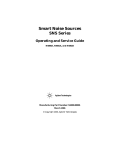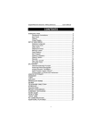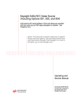
1
IPU 40060 Issue 9 IRISYS Universal Thermal Imager Type IRI 1011 User Manual Safety Warning: The equipment described in this document uses a Class II laser. Under no account should anyone look directly into the laser beam or the laser beam exit aperture, irreversible damage to the eye may occur. The laser should not be operated when there are personnel in the imager’s field of view. Caution – use of controls or adjustments or performance of procedures other than those specified in this document may result in hazardous laser radiation exposure. InfraRed Integrated Systems Ltd Park Circle, Tithe Barn Way, Swan Valley, Northampton, NN4 9BG Tel: (0) 1604 594200 Fax: (0) 1604 594210 Email: [email protected] Conforms to USA 21 CFR 1040.10. Class II laser product. 2004 InfraRed Integrated Systems Ltd Page 1 of 27 IPU 40060 Issue 9 Contents: 1 GETTING STARTED..................................................................................... 3 1.1 UNPACKING .............................................................................................. 3 1.2 POWERING THE IRI 1011 ............................................................................. 3 1.2.1 Using Battery Power .......................................................................... 3 1.2.2 Using AC Mains Power ........................................................................ 4 1.3 CONNECTING THE IRI 1011 TO A ‘POCKET PC’ OR PALM ......................................... 4 2 OPERATING THE IRI 1011 THERMAL IMAGER ............................................ 5 2.1 HARDWARE ............................................................................................... 5 2.2 USING THE LASER POINTER ............................................................................ 6 2.3 USING THE IRI 1011 THERMAL IMAGER WITH A ‘POCKET PC’.................................... 6 2.3.1 Setting up the ‘Pocket PC’ with the IRI 1011 Thermal Imager.................. 6 2.3.1.1 Installing the IRISYS 1011 Imager software onto a ‘Pocket PC’ .........................6 2.3.1.2 Starting the IRISYS 1011 Imager software.....................................................7 2.3.1.3 Reinstalling the IRISYS 1011 Imager software onto a ‘Pocket PC’ from Flash Memory. 7 2.3.2 Operating the ‘Pocket PC’ with the IRI 1011 Thermal Imager .................. 7 2.3.2.1 Software Button Operations .........................................................................8 2.3.2.2 Navigation/Action Button Operations ........................................................... 10 2.3.2.3 Snapshot Transfer from a ‘Pocket PC’ to a PC ............................................... 10 2.3.3 Recommended ‘Pocket PCs’ for use with the IRI 1011 ..............................11 2.4 USING THE IRI 1011 THERMAL IMAGER WITH A PALM ...........................................12 2.4.1 Setting up the Palm with the IRI 1011 Thermal Imager .........................12 2.4.1.1 Installing the IRISYS 1011 Imager software onto a Palm ............................... 12 2.4.1.2 Switching off the Palm’s automatic shutdown ............................................... 13 2.4.1.3 Starting the IRISYS 1011 Imager software................................................... 13 2.4.2 Operating the Palm with the IRI 1011 Thermal Imager..........................14 2.4.2.1 Software Button Operations ....................................................................... 14 2.4.2.2 Navigation/Action Button Operations ........................................................... 15 2.4.3 Recommended Palms for use with the IRI 1011....................................16 2.5 USING THE IRI 1011 THERMAL IMAGER WITH A PC ..............................................17 2.5.1 Installation of software on PC.1000 Report Writer note..........................17 2.5.2 Operating IRISYS 1011 Imager software .............................................17 2.5.2.1 2.5.2.2 2.5.2.3 2.5.2.4 2.5.2.5 3 OPERATING NOTES AND PRECAUTIONS................................................... 21 3.1 3.2 4 Turning off Microsoft ActiveSync: ................................................................ 17 Control Panel............................................................................................ 18 Menus ..................................................................................................... 19 Producing a Temperature Graph (live imaging):............................................ 20 Use of PC software with no Thermal Imager connected .................................. 20 TEMPERATURE MEASUREMENT .........................................................................21 GENERAL.................................................................................................21 OPTIONAL ACCESSORIES......................................................................... 21 4.1 IRI 1011 HANDLE .....................................................................................21 4.1.1 Mounting the imager and Pocket PC onto the Handle.............................21 4.1.2 Preparing the Handle for use with a Palm PC. .......................................25 4.1.3 Removing the Imager from the Handle. ...............................................26 5 CUSTOMER FEEDBACK ................................................................................ 27 Page 2 of 27 IPU 40060 Issue 9 1 Getting Started This User Manual refers to the IRISYS Universal Thermal Imager system type IRI 1011, for use with a ‘Pocket PC’, Palm or a PC. 1.1 Unpacking After unpacking the IRI 1011 toolbox, you will find the standard items as shown in Figure 1. Figure 1: Contents of the IRI 1011 Universal Thermal Imager Toolbox Carry Case Regional Mains Adapters CD-Rom RS232 Connection Cable for a PC IRI 1011 Thermal Imager Battery Holder With 4 AA Size Batteries Inspect all the items. immediately. 12V Power Supply If any item is damaged or missing, notify your dealer 1.2 Powering the IRI 1011 The IRI 1011 Thermal Imager operates from either 4 standard AA size batteries, or from AC mains power. 1.2.1 Using Battery Power 1. Make sure the Thermal Imager is turned off. Figure 4, shows where the on/off button is. 2. Open up the battery compartment on the bottom of the IRI 1011 Thermal Imager, by sliding the battery cover off. 3. Carefully remove the battery holder and insert 4 AA size batteries. Standard AA Alkaline batteries or rechargeable batteries can be used. The polarity of the batteries is shown on the holder. 4. Replace the battery holder, making sure that the connector is positioned so that it is towards the centre of the imager, and replace the battery cover. CAUTION: Do not use a 9V battery. Figure 2: Inserting 4 AA Size Batteries into the IRI 1011 Battery Compartme Battery Cover Empty Battery Holder Page 3 of 27 Battery Holder with 4 AA size batteries IPU 40060 Issue 9 NOTE: • A set of 4 AA batteries will power the IRISYS IRI 1011 Universal Thermal Imager for approximately 8 hours. CAUTION: If the IRI 1011’s red LED starts flashing it means that the batteries are running low and need to be replaced immediately. 1.2.2 Using AC Mains Power 1. Make sure the Thermal Imager is turned off. 2. Connect the provided 12V power supply into the socket on the side of the IRI 1011 imager, see Figure 4. 3. Attach the appropriate supplied regional adapter to the power supply. 4. Plug the power supply into a mains socket. 5. Switch on the thermal imager. CAUTION: When using AC mains, use only the power supply included with the IRI 1011. Using other power supplies may damage the IRI 1011 Thermal Imager. NOTE: • It is recommended that the IRISYS Universal Thermal Imager (not the ‘Pocket PC’/Palm) should be switched on approximately 2 minutes before use. This is to allow the internal electronics to warm up and stabilise, so as to achieve optimum performance. • The mains power supply included with the IRI 1011 is only for powering the IRI 1011; it will not recharge the batteries. 1.3 Connecting the IRI 1011 to a ‘Pocket PC’ or Palm • This section tells you step by step how to get the Thermal Imager up and running with a ‘Pocket PC’/Palm. 1. Make sure the IRI 1011 is powered by either 4 AA size batteries or the 12V power supply. 2. Make sure the Thermal Imager software has been installed onto the ‘Pocket PC’ or Palm, see Section 2.3.1.1 or Section 2.4.1.1 respectively. 3. Connect the Pocket PC’s/Palm’s RS232 serial sync cable into its socket and the other end into the IRI 1011 RS232 socket, see Figure 3. Figure 3: The IRI 1011 Thermal Imager connected to a ‘Pocket PC’, configured for two handed operation Pocket PC, not supplied with IRI 1011 IRI 1011 Therm al Imager Pocket PC Manufactur er’s RS232 Serial Sync Cable Page 4 of 27 IPU 40060 Issue 9 2 Operating the IRI 1011 Thermal Imager This section provides information for using the IRI 1011 Universal Thermal Imager. Described in this section are: • • • • • The Hardware Using the Laser Pointer Using the IRI 1011 Thermal Imager with a ‘Pocket PC’ Using the IRI 1011 Thermal Imager with a Palm Using the IRI 1011 Thermal Imager with a PC 2.1 Hardware The IRI 1011 system is designed for use with a ‘Pocket PC’, Palm or a PC. For use with a ‘Pocket PC’ or Palm the imager is connected via an RS232 serial sync cable, see Section 2.3.3 or Section 2.4.3 respectively for recommended cables. For a PC or laptop computer use the RS232 serial cable supplied with the imager. Figure 4: The IRISYS IRI 1011 Universal Thermal Imager. On/Off switch and power on LED Indicator Off – right On – left Laser Pointer Aperture Lens Laser Pointer Button DC socket, used for connecting to mains power Battery Compartment Laser Pointer Button Laser Pointer Button RS232 Socket, for connecting to a ‘Pocket PC’, Palm or a PC Safety notice: The laser used in this device is designated Class II. Under no circumstances should personnel look straight into the laser. Components of the IRI 1011 Thermal Imager: • • • The IRI 1011 Thermal Imager can be connected to a ‘Pocket PC’ or Palm via an RS232 serial sync cable, see Section 1.3. To use the IRI 1011 with an IBM compatible PC, the supplied RS232 serial cable is inserted into the socket on the bottom of the unit, and the other end connects into a COM port on the PC. Operation with a PC is independent of the ‘Pocket PC’/Palm. The IRI 1011 features an ON/OFF power switch on the front. The ‘Pocket PC’/Palm has a separate power switch. Page 5 of 27 IPU 40060 Issue 9 2.2 Using the Laser Pointer The Laser pointer is used to allow the operator to illuminate and identify the centre of the scene that the Thermal Imager is viewing. When the IRI 1011 unit is switched ‘ON’, the laser may be operated by pressing and holding any of the three red buttons on the Imager, see Figure 4. The laser pointer illuminates the area of the scene that is viewed by the “default” temperature measurement pixel. The default temperature measurement pixel is the central point on the ‘Pocket PC’ or Palm display screen, which is indicated by a red circle, see Figures 5 or 9 respectively. The length of the laser bar gives an indication of the pixel dimension. In order for the IRI 1011 to give an accurate temperature reading the minimum area of the scene being viewed must be a square that totally encloses the laser bar. The laser pointer is therefore a useful tool for finding the maximum viewing range of the IRI 1011 in specific applications. 2.3 Using the IRI 1011 Thermal Imager with a ‘Pocket PC’ Most ‘Pocket PCs’ can be used with the IRI 1011 Universal Thermal Imager. This section will describe some of the basic functions of ‘Pocket PCs’ with the IRI 1011. These functions are common to many different available brands of ‘Pocket PC’s. 2.3.1 Setting up the ‘Pocket PC’ with the IRI 1011 Thermal Imager 2.3.1.1 Installing the IRISYS 1011 Imager software onto a ‘Pocket PC’ The IRI 1011 Thermal Imager can be used with most ‘Pocket PCs’, which have an RS232 serial port and run Microsoft ‘Pocket PC’ 2000, 2002 or 2003, see Section 2.3.3 for recommended ‘Pocket PC’s. The ‘Pocket PC’ can be used to display, process and store snapshots of thermal images. 1. Ensure that ActiveSync is installed on your PC from the CD supplied with your Pocket PC, and that it is communicating with your ‘Pocket PC.’ 2. Refer to your ‘Pocket PC’ User Manual for more information on ActiveSync and synchronising your ‘Pocket PC’ with a PC. It is not necessary to create an ActiveSync synchronized partnership between the two. If you are given the option to choose between a “standard” and a “guest” partnership, select “guest”. Note: If you are having difficulty connecting, try going into the ActiveSync connection settings dialog screen and “ticking” both the ‘allow serial’ and ‘allow USB’ connection boxes. 3. Make sure the ‘Pocket PC’ is switched on, and connected to the PC. 4. Insert the IRISYS 1011 Imager software (supplied on a CD-Rom with your IRI 1011) into your PC’s CD-Rom Drive. 5. Double click on ‘My Computer’ and then on the ‘CD-Drive (D:)’. 6. Double click on the folder “CE Install” 7. Double click on ‘1000 Series CE Setup.exe’ to start the installation. 8. Follow the on screen prompts, to complete the installation. NOTE: • While the Thermal Imager may be used solely with the ‘Pocket PC’, access to a PC is necessary for installing the Thermal Imager’s software to the 'Pocket PC’. • If the ‘Pocket PC’ has Flash memory or a memory card, the IRISYS ‘Pocket PC’ software will automatically be saved onto this memory during the initial installation. • As an alternative to the portable use of the IRI 1011 using a ‘Pocket PC’, the output of the imager can be displayed and processed in real time using a PC, see Section 2.5 for using the IRI 1011 with a PC. Page 6 of 27 IPU 40060 Issue 9 2.3.1.2 Starting the IRISYS 1011 Imager software 1. Check that the ‘Pocket PC’ is charged. 2. Make sure the ‘Pocket PC’ is connected to the IRI 1011 Thermal Imager with an RS232 serial sync cable. The serial sync cable is either supplied with the ‘Pocket PC’ as a standard item or can be ordered from the ‘Pocket PC’ supplier as an accessory. 3. Switch on the ‘Pocket PC’ and the Thermal Imager. 4. Using the Stylus pen from the ‘Pocket PC’, select the Start menu and then select the Programs folder. Select the icon labelled “IRISYS 1000+ Imager”. 5. Operation of the IRISYS 1011 Imager application is by means of the Navigation/Action button and software buttons. See Sections 2.3.2.2 for further information. NOTE: • The IRISYS Imager program takes a few seconds to load. • If the ‘Pocket PC’ battery is allowed to fully discharge, the imager software will be lost and must be re-installed either from memory storage or from the CD again. The ‘Pocket PC’ uses power even when it is switched off. Regular recharging and transferral of images is therefore recommended. 2.3.1.3 Reinstalling the IRISYS 1011 Imager software onto a ‘Pocket PC’ from Flash Memory. The imager software can be re-installed from flash memory storage on newer Pocket PC’s using File Explorer. For example on HP iPAQs, open “File Explorer”, first select “My Device” from the drop down menu at the top of the screen, then select “iPAQ File Store” and finally “1000 Series Imager”. Select “OK” to confirm re-installation. 2.3.2 Operating the ‘Pocket PC’ with the IRI 1011 Thermal Imager Figure 5: Screenshot of IRISYS 1011 Imager ‘Pocket PC’ Software Default Laser Pixel Selected Temperature Range Temperature cursor and corresponding temperature reading Temperature difference between the two selected temperature cursors Temperature Range Pocket PC Battery Indicator Page 7 of 27 IPU 40060 Issue 9 NOTE: • For optimum performance the imager should be switched ‘ON’ and allowed to settle for about 2 minutes. • Should the ‘Pocket PC’ lock up you will need to perform a soft reset of the ‘Pocket PC’. The Reset button for most ‘Pocket PCs’ is located on the side or bottom. Refer to your ‘Pocket PC’ User Manual for more information on Resets. 2.3.2.1 Software Button Operations Figure 6: Buttons used within the IRISYS 1011 Imager software. Browse Allows the user to browse and delete saved snapshots. Grab Takes a snapshot of the image. Auto Automatically adjusts the temperature range and sensitivity. Tools Allows the user to set a number of parameters, e.g. emissivity. Exit Closes down the IRISYS 1011 Imager software. Grab Takes a snapshot of the currently displayed image. The user is asked ‘Do you wish to save this image?’ The user must select ‘Yes’ or ‘No’. Pressing ‘No’ will discard the snapshot and return to ‘Live’ mode. Pressing ‘Yes’ will save the image with the name ‘Snapshot n.snp’, where n is the next available number in the sequence starting from 1. NOTE: • All the setting and cursor functions may be applied to the grabbed image frames. • Go to ‘Browse’ to view saved snapshots. Auto The Auto button can be set in the ‘Tools’ section to operate in two different modes: • • Tools Gives access • • • • “Ticked box” Continuous Auto - Continuously adjusts the temperature range and sensitivity of the image for ease of viewing. In this mode the ‘Auto’ button can be used to switch Continuous Auto on or off. “Unticked box” Continuous Auto - The ‘Auto’ button is used in a one shot mode i.e. each time the button is pushed it will automatically adjust the temperature range and sensitivity for the present scene. With Continuous Auto off, the image can be adjusted in a manual mode using the Nav/Action button, see Section 2.3.2.2 for more information. to the following settings: Image Label – The user can enter their own selected name for saved snapshots. Image Folder – The user can set the path directory to which snapshot images are saved. Ambient (oC) – The user can set the ambient temperature; if the emissivity (see below) is not given the value of 1 the software compensates for the ambient temperature to give more accurate temperature readings. Value entered must be within the range -20ºC to 200ºC. Calibration – If there is more than one calibration file available for the imager, the user can select the appropriate file from this box. If there is only one calibration file this selection box may not be displayed. Page 8 of 27 IPU 40060 Issue 9 • • • • • • • Emissivity – The user can select the emissivity for the material being imaged. Setting the correct emissivity value is important to achieve the accuracy of temperature readings, see note 3 in Section 3.1. Colour Map – The user can select one of three possible colour options: o Greyscale o Red-Blue o Green-Blue Integration – The number of image frames to be integrated can be set to ‘Integration OFF’ or up to 10 frames. Note that this function reduces “noise” on the image; it should be turned off when imaging a moving scene. Temp. Units – The user can select the temperature units to be: o Celsius (oC) o Fahrenheit (oF) o Kelvin (K) Interpolate – The user can select a displayed resolution, of 16x16 pixels or 96x96 pixels. 2nd Element – The user can select whether to have the second (SP2) temperature cursor displayed on the screen. Continuous Auto – See section on ‘Auto’ above for further explanation. Figure 7: Tools menu within the IRISYS 1011 Imager software. Image Label Image Folder Ambient Temperature Emissivity Calibration File Colour Map Integration Toggle Interpolate Toggle 2nd Element Toggle Temperature Units Continuous Auto Browse Gives access to five other buttons: • Prev – Loads the previously stored snapshot file. • Next – Loads the next stored snapshot file. • Delete – Deletes the current snapshot. The user will be asked ‘Are you sure? Yes/No’. • Tools – Takes the user back to the ‘Tools’ Menu, (see Tools above). • Live – Returns the user to Live imaging mode. Exit Shuts down the IRISYS 1011 Imager software application. Page 9 of 27 IPU 40060 Issue 9 2.3.2.2 Navigation/Action Button Operations All ‘Pocket PCs’ have a central Navigation/Action button. This is the only physical button used for operating the IRISYS 1011 Imager software. The remaining buttons on the ‘Pocket PC’ are used for other applications outside of the IRISYS software. The function of these buttons is dependant on the brand of ‘Pocket PC’. The Navigation/Action button can be depressed at five points and has five primary functions up, down, left, right and select. Figure 8: The Navigation/Action button of an HP iPAQ 5000 Series ‘Pocket PC’ UP Select Option (Action) LEFT RIGHT DOWN With ‘Auto’ adjust toggled OFF, pressing the centre of the Navigation/Action button will cycle through three options. The selected option is indicated by a flashing red outline surrounding the box. The three options are: 1. Manual control of the sensitivity and temperature range bar. This can be used in snapshot mode, or when ‘Auto’ adjust is toggled OFF. • The Sensitivity and temperature range of the displayed image can be manually adjusted by use of the Navigation/Action button. Pressing up/down adjusts the sensitivity and pressing left/right adjusts the temperature range. 2. Selected Temperature Cursor (SP1). • The SP1 cursor can be moved around the screen on the thermal image by using the Navigation/Action button, i.e. up/down/left/right. 3. Selected Temperature cursor (SP2). • The SP2 cursor can be moved around the screen on the thermal image by using the Navigation/Action button, i.e. up/down/left/right. When the ‘Auto’ adjust is toggled ON, pressing the Nav/Action button will cycle between the two temperature cursors, and not the manual control bar. 2.3.2.3 Snapshot Transfer from a ‘Pocket PC’ to a PC Microsoft ActiveSync must be installed to be able to transfer Snapshot images from the ‘Pocket PC’ to a PC. Refer to your ‘Pocket PCs’ User Manual for more information on Microsoft ActiveSync. In order to transfer a Snapshot file from the ‘Pocket PC’ to the PC follow this procedure: 1. Ensure that ActiveSync is installed on your PC and communicating with your ‘Pocket PC.’ 2. Refer to your ‘Pocket PC’ User Manual for more information on ActiveSync and synchronising your ‘Pocket PC’ with a PC. 3. On the PC, from the File menu in ActiveSync select “Explore”. This will open a “Mobile Device” window. If the folder appears to be empty, select “Refresh” from the View menu 4. Double click on “My Pocket PC”. Page 10 of 27 IPU 40060 Issue 9 5. Double click on “My Documents” then select Snapshots, or click on the folder in which the snapshots have been saved. The folder in which snapshots are saved can be selected on the ‘Pocket PC’; see Tools in Section 2.3.2.1. The snapshots will have extensions “.snp” 6. Copy the required Snapshots to a suitable folder on the PC (click and drag; or right click-copy then right click-paste into the folder). NOTE: • It is advisable to periodically download saved Snapshot images from the ‘Pocket PC’ to a PC. If a ‘Pocket PC’ battery runs flat, all saved images on the ‘Pocket PC’ will be lost, unless they are saved into Flash memory or onto a memory card (e.g. an SD card). 2.3.3 Recommended ‘Pocket PCs’ for use with the IRI 1011 Table 1, lists some 'Pocket PCs' IRISYS have tested with the IRI 1011. This table is the current IRISYS view on ‘Pocket PCs’, as of March 2005. For an up to date list of recommended ‘Pocket PC’s, please see the IRISYS website, www.irisys.co.uk. Please note that it is necessary to acquire the appropriate synchronization cable for a specific ‘Pocket PC’. The URL links provided in Table 1 for cable suppliers are intended as an example. For more information on synchronization cables it is advisable to contact your local manufacturer (e.g. HP) or supplier. Table 1: ‘Pocket PCs’ tested with the IRI 1011, and recommended RS232 serial sync cable. ‘Pocket PC’ HP RZ1710 HP iPAQ hx2000 series HP iPAQ H5100 & H5500 series HP iPAQ H4150 series HP iPAQ rx3700 series HP iPAQ hx 4700 series HP H2210 O2 XDA Synchronizing cable (not supplied) Universal Autosync Cable. HP part number FA122A EXpansys Code: 101828. Universal Autosync Cable. HP part number FA122A EXpansys Code: 101828 Universal Autosync Cable. HP part number FA122A EXpansys Code: 101828 Universal Autosync Cable. HP FA122A#AC3 EXpansys code: 101828 Universal Autosync Cable. HP part number FA122A EXpansys Code: 101828 Universal Autosync Cable. HP part number FA122A EXpansys Code: 101828 Universal Autosync Cable. HP part number FA122A EXpansys Code: 101828 O2 Serial Autosync cable for XDA. EXpansys Code: 104141. Page 11 of 27 Comments Entry level system Not tested by IRISYS IPU 40060 Issue 9 2.4 Using the IRI 1011 Thermal Imager with a Palm A number of Palm models can be used with the IRI 1011 Universal Thermal imager, see Section 2.4.3 for recommended Palms. The system requirements for the Palm are an operating system of OS® 5.2.1 or above, serial RS232 connectivity and a 320 x 320 display supporting 16 bit colours. The Palm can be used to display, process and store snapshots of thermal images. 2.4.1 Setting up the Palm with the IRI 1011 Thermal Imager 2.4.1.1 Installing the IRISYS 1011 Imager software onto a Palm The following is a step by step guide for installing the IRISYS 1011 imager software onto a Palm: 1. Install the ‘HotSync’ software, from the CD supplied with your Palm, on to a PC. HotSync allows you to transfer and synchronize data on your PC with your Palm, and vice versa. For more information on HotSync, please refer to your Palm Handbook. The final part of this will require you to carry out your first ‘HotSync’ operation. i) Place your Palm in its cradle or connect it to its cable. Make sure the cradle/cable is connected to your PC ii) Press the HotSync icon on your Palm display. iii) A new window will open on your Palm stating whether it is set up for a ‘Local’ or ‘Modem’ connection. Make sure ‘Local’ is selected. iv) Press the HotSync button on your cradle/cable or on the Palm screen. 2. Insert the IRISYS supplied CD into your PC’s CD-ROM drive. 3. Open the folder ‘CD:\IRI 1011 Palm\1000 Series Palm\’. 4. Double click on the ‘1000 Series Palm Setup.exe’ file, and follow the onscreen prompts. This can take a while. Please wait until the final complete screen below appears. 5. If there is a window asking you to add one or both of the following files, “1011 ThermalImager” and ‘MathLib.prc’ file to your Handheld Palm, select ‘OK’. 6. Follow the procedure for HotSync. i) Press the HotSync icon on your Palm display. ii) A new window will open on your Palm stating whether it is set up for a ‘Local’ or ‘Modem’ connection. Make sure ‘Local’ is selected. iii) Press the HotSync button on your cradle/cable or on the Palm screen. 7. This completes the installation of the Palm software. 8. In the event that the following message appears “you must finish installing previous programs before installing more” even though the installation HAS finished. It means that the list of applications to be installed contains some that are already installed. If the message persists, remove the programs from the list and rerun the 1000 series Palm setup. Page 12 of 27 IPU 40060 Issue 9 9. After you have saved some images on the PALM device, the next time you HotSync, the images will be automatically transferred to a folder on to your PC. The default folder is usually C:\Program Files\Palm\TT\IRISYS. NOTE: • While the Thermal Imager may be used solely with the Palm, access to a PC is necessary for installing the Thermal Imager’s software to the Palm. • As an alternative to the portable use of the IRI 1011 using a Palm, the output of the imager can be displayed and processed in real time using a PC, see Section 2.5 for using the IRI 1011 with a PC. 2.4.1.2 Switching off the Palm’s automatic shutdown When the Palm is being used from its batteries, it short period of time to conserve the battery life. period for automatic shut down, it is necessary to your Palm. ‘AlwaysOn’ is free software and can be will automatically shut down after a To change, or switch off the time install the ‘AlwaysOn’ software onto downloaded from the Palm website: The following is a step by step guide for installing the ‘AlwaysOn V1.2’ software onto your Palm: 1. Place your Palm in its cradle or connect it to its cable. Make sure the cradle/cable is connected to your PC. 2. Press the HotSync icon on your Palm display. 3. A new window will open on your Palm stating whether it is set up for a ‘Local’ or ‘Modem’ connection. Make sure ‘Local’ is selected. 4. Press the HotSync icon in the middle of the Palm screen. 5. Download the ‘AlwaysOn’ software from the Palm website: http://palmsource.palmgear.com/index.cfm?fuseaction=software.showsoftware &SID=5290900C-CF18-AC90-838C210BE1658BDE&PartnerREF=&prodID=1499 6. Double click on the ‘AlwaysOn.prc’ file. 7. A new window will pop up asking you to ‘Confirm Add’ of the ‘AlwaysOn12.prc’ file to your Handheld Palm, select ‘OK’. 8. Press the HotSync icon on your Palm display. 9. A new window will open on your Palm stating whether it is set up for a ‘Local’ or ‘Modem’ connection. Make sure ‘Local’ is selected. 10. Press the HotSync icon in the middle of the Palm screen. This completes the installation of the ‘AlwaysOn’ software. An ‘AlwaysOn’ icon will appear on your Palm’s menu screen. Press the icon to be shown a list of time periods that can be selected for automatic shut down. 2.4.1.3 Starting the IRISYS 1011 Imager software 1. Check that the Palm is charged. 2. Make sure the Palm is connected to the IRI 1011 Thermal Imager with the connection cable. 3. Switch on the Palm and the Thermal Imager. 4. Using the Stylus pen from the Palm, select the Thermal Imager icon to launch the application. 5. Operation of the IRISYS 1011 Imager application is by means of the Navigation/Action button and software buttons. See Section 2.4.2.2 for further information. NOTE: • The IRISYS Imager application takes a few seconds to load. • If the Palm battery is allowed to fully discharge, the imager software will be lost and must be re-installed onto the Palm. The Palm uses power even when it is switched off. Regular recharging is therefore recommended. • If for any reason the software locks up, perform a ‘soft reset’ on the Palm. See your Palm Handbook for more information on resetting. Page 13 of 27 IPU 40060 Issue 9 2.4.2 Operating the Palm with the IRI 1011 Thermal Imager Figure 9: Screenshot of IRISYS 1011 Imager Palm Software Selected Temperature Range Default laser pixel Temperature difference between the two selected temperature cursors Temperature cursor and corresponding temperature Palm battery indicator Temperature Range NOTE: For optimum thermal imaging performance the imager should be switched ‘ON’ and allowed to settle for about 2 minutes. 2.4.2.1 Software Button Operations Figure 10: Buttons used within the IRISYS 1011 Imager software. Grab Takes a snapshot of the image. Browse Allows the user to browse and delete saved snapshots. Auto Automatically adjusts the temperature range and sensitivity. Tools Allows the user to set a number of parameters, e.g. emissivity. Grab Takes a snapshot of the currently displayed image. The user is asked ‘Do you wish to save this snapshot?’ The user must select ‘Yes’ or ‘No’. Pressing ‘No’ will discard the snapshot and return to ‘Live’ mode. Pressing ‘Yes’ will save the image with the name ‘Snapshot n.snp’, where n is the next available number in the sequence. Also the snapshot will be labelled with the date and time at which it was saved. NOTE: • All the settings and cursor functions may be applied to the grabbed image frames. • Go to Browse to view saved snapshots. Page 14 of 27 IPU 40060 Issue 9 Auto The Auto button can be set in the ‘Tools’ section to operate in two different modes: • “Ticked box” Continuous Auto - Continuously adjusts the temperature range and sensitivity of the image for ease of viewing. In this mode the ‘Auto’ button can be used to switch Continuous Auto on or off. • “Unticked box” Continuous Auto - The ‘Auto’ button is used in a one shot mode i.e. each time the button is pushed it will automatically adjust the temperature range and sensitivity for the present scene. With Continuous Auto off, the image can be adjusted in a manual mode using the Nav/Action button, see Section 2.4.2.2 for more information. Tools Gives access to the following settings: • Image Label – The user can enter their own selected name for saved snapshots. • Ambient (oC) – The user can set the ambient temperature; if the emissivity (see below) is not given the value of 1 the software compensates for the ambient temperature to give more accurate temperature readings. Limited to 200ºC if value entered is above 200ºC. • Calibration – If there is more than one calibration file available for the imager, the user can select the appropriate file from this box. If there is only one calibration file this selection box may not be displayed. • Emissivity – The user can select the emissivity for the material being imaged. Setting the correct emissivity value is important to achieve the accuracy of temperature readings, see note 3 in Section 3.1. • Colour Map – The user can select one of three possible colour options: o Greyscale o Red-Blue o Green-Blue • Integration – The number of image frames to be integrated can be set to ‘Integration OFF’ or up to 10 frames. Note that this function reduces “noise” on the image; it should be turned off when imaging a moving scene. • Temp. Units – The user can select the temperature units to be: o Celsius (oC) o Fahrenheit (oF) o Kelvin (K) • Interpolate – The user can select a displayed resolution, of 16x16 pixels or 96x96 pixels. • 2nd Element – The user can select whether to have the second (SP2) temperature cursor displayed on the screen. • Continuous Auto – See section on ‘Auto’ above for further explanation. Browse Gives access to five other buttons: • Prev – Loads the previously stored snapshot file. • Next – Loads the next stored snapshot file. • Del – Deletes the current snapshot. The user will be asked ‘Are you sure? Yes/No’. • Tools – Takes the user back to the ‘Tools’ Menu, (see Tools above). • Live – Returns the user to Live imaging mode. 2.4.2.2 Navigation/Action Button Operations All Palms have a central Navigation/Action button. This is the only physical button used for operating the IRISYS 1011 Imager software. The remaining buttons on the Palm are used for other applications outside of the IRISYS software. The function of these buttons is dependant on the brand of Palm; refer to your Palm Handbook for more information. The Navigation/Action button can be depressed at five points and has five primary functions up, down, left, right and select. Page 15 of 27 IPU 40060 Issue 9 Figure 11: The Navigation/Action button of aTungstenT3 Palm UP LEFT SELECT RIGHT DOWN With ‘Auto’ adjust OFF; pressing the centre of the Navigation/Action button will cycle through three options. The selected option is indicated by a flashing red outline surrounding the box. The three options are: 1. Manual control of the sensitivity and temperature range bar. This can be used in snapshot mode, or when ‘Auto’ adjust is OFF. • The Sensitivity and temperature range of the displayed image can be manually adjusted by use of the Navigation/Action button. Pressing up/down adjusts the sensitivity and pressing left/right adjusts the temperature range. 2. Selected Temperature Cursor (SP1). • The SP1 cursor can be moved around the screen on the thermal image by using the Navigation/Action button, i.e. up/down/left/right. 3. Selected Temperature cursor (SP2). • The SP2 cursor can be moved around the screen on the thermal image by using the Navigation/Action button, i.e. up/down/left/right. When the ‘Auto’ adjust is ON, pressing the Nav/Action button will cycle between the two temperature cursors only, and not the manual control bar. 2.4.3 Recommended Palms for use with the IRI 1011 Table 2, lists some of the Palms IRISYS have tested with the IRI 1011. This table is the current IRISYS view on Palms, as of March 2005. For an up to date list of recommended Palms, please see the IRISYS website, www.irisys.co.uk. The URL links provided in Table 2 for cable suppliers are intended as an example. For more information on synchronization cables it is advisable to contact your local manufacturer or supplier. Palm Zire 71 Tungsten T3 Synchronizing cable (not supplied) Palm Universal HotSync Cable. Web site: http://www.expansys.com/product.asp?code= M500USBSERY Universal HotSync Cable. EXpansys Code: 103725. Web site: http://www.expansys.com/product.asp?code= M500USBSERY EXpansys Code: 103725. Comments Works very well. Works very well. Table 2: Palms tested with the IRI 1011, and recommended serial sync cable. Page 16 of 27 IPU 40060 Issue 9 2.5 Using the IRI 1011 Thermal Imager with a PC The PC should be IBM compatible running MS Windows XP or 2000, with an RS232 serial port, USB port and 24 bit colour graphics. If a laptop PC is used, a TFT display is recommended. This application can be used for online imaging with the IRI 1011 connected to the PC or for analysis of snapshots previously saved on a ‘Pocket PC’ or Palm. 2.5.1 Installation of PC and 1000 series report writer software NOTE: • 1000 series report writer software instructions can be found in the user manual IPU40104 Both software’s are on the supplied CD-Rom. 1. 2. 3. 4. 5. Insert the supplied CD-Rom into the PC’s CD-Drive (D:). Double click on ‘My Computer’ and then on the ‘CD-Drive (D:)’. Double click on the “PC Install” folder. Double click on ‘1000 Series PC Setup.exe’. Follow the on screen prompts to complete the installation. NOTE: • The IRISYS 1011 Imager software will by default be installed into the following path: C:\Program Files\IRISYS\IRISYS 1000 Series Imager • The above path and name can be changed during the installation, but it is advisable to leave it as the default. The installation will also put a ‘Shortcut Icon’ onto your PCs desktop to allow quick and easy start-up of the software. Please note, 1000 series report writer software instructions can be found in user manual IPU40104. • 2.5.2 Operating IRISYS 1011 Imager software Connect the Thermal Imager to the PC using the RS232 cable provided. Launch the IRISYS 1011 Imager program from the Desktop icon, or from: START/PROGRAMS/IRISYS/IRISYS 1000 Series Imager When launched, the window obtained will be similar to Figure 12. On initial launch, if the Thermal Imager is not connected or switched on, the message “NO INCOMING DATA” will appear in the status box. The image window will contain the last viewed image, and the temperature displayed will be from the last viewed image. On connecting the Thermal Imager to the PC and switching it on, the program will make connection with the imager (this may take several seconds). On some PC’s, after connecting the imager, it may be necessary to close the IRISYS 1000 Series Imager application, and then reopen it. This allows the program to detect the COM port that the imager is using. The status box contains information on the settings of the imager, and the co-ordinates of the selected cursor whose temperature output is displayed in the temperature window. 2.5.2.1 Turning off Microsoft ActiveSync: A common problem when communicating with the Thermal Imager is that the Microsoft ActiveSync program has “taken over” the available COM port. This may be rectified as follows: 1. Open the ActiveSync program (either by the Icon at the bottom right of the PC screen or from the Desktop). 2. From the File menu select “Connection Settings”. 3. “Un-tick” the “Allow serial cable or infrared connection to this COM port” box, if already ticked. If not required, the Ethernet box should be “Un-ticked”. 4. ‘OK’ the Connection Settings window, and ‘Close’ the ActiveSync window. 5. Remember to “re-tick” the serial cable connection box after use if it is needed for other applications. Page 17 of 27 IPU 40060 Issue 9 2.5.2.2 Control Panel The Controls in the control panel are as follows: • • • • • • • • • • • Sensitivity – see below for explanation. Range – see below for explanation. Resolution – sets the level of interpolation from 16 X 16 up to 128 X 128. Colour map – sets the display in greyscale, red-blue or blue-green. Orientation – the image can be rotated around to different orientations. Temperature Graph time scale – sets the temperature graph range. Ambient – set the ambient temperature. Emissivity – select a value to suit the object under examination, see Note 3 in Section 3.1. Calibration Set – The calibration file is displayed in this box. Temperature units – choose oCelsius, oFahrenheit or Kelvin. Integration – sets the number of frames to integrate, up to ten maximum. Figure 12: Thermal Imager launch window Temperature Display Window Selected Temperature Range Status Box Laser Default Pixel Image Window Adjusting the displayed Thermal Image: • • • The sensitivity and range can be automatically adjusted for a single image by clicking on the ‘Single Auto Gain’ button. For continuous automatic adjustment the ‘Continuous Auto Gain’ button should be selected, this button is on the tool bar, see Figure 13. To use the manual controls whilst imaging live, it is necessary to first toggle off the ‘Continuous Auto Gain’ button. The horizontal scroll bars can be used to manually adjust the displayed image’s sensitivity and range. The ‘Sensitivity’ number indicates how many degrees span the image from black (cold) to white (hot). The range numbers represent the upper and lower values of temperature from black (cold) to white (hot). Page 18 of 27 IPU 40060 Issue 9 2.5.2.3 Menus Figure 13: Thermal Imager Tool Bar Take Snapshot Edit Emissivities Edit Colour Map Toggle Toggle Temperature Controls Graph Continuous Auto Gain Single Auto Gain Live Display The File menu allows the following: • New – opens a new imager window, which may be set up to run under its own set of controls. • Open… – opens a previously stored image. • Close – closes the current window. • Save – saves the current window as a scene data file. • Save As… – saves the current window as a new scene data file. • MS Excel output… – saves data in CSV format from the temperature/time graph ready for use in a spreadsheet. Output of either the selected pixel(s) or all pixels can be saved to MS Excel at a suitable up date interval. • Snapshot n – A list of previously saved snapshots. • Exit – Exits program. The Edit menu allows the following: • Copy (Ctrl C) – takes a copy of the image, it can then be pasted into another document e.g. MS Word. • Copy to bitmap – copies image to a ‘.bmp’ file. • Snapshot – takes a snapshot of the image and saves it as a scene data file. The View • • • • menu allows the following: Toolbar - Turn the Tool Bar on and off. Status Bar - Turn the Status Bar on and off. Control Panel - Turn the Control Panel on and off. Temperature Graph - Turn the Temperature Graph on and off. The Tools menu allows access to: • Emissivity editor – allows the editing of the emissivity tables. • Colour map editor –allows the editing of the colour map editor. • Edit Label – allows the editing of the labels for saving the images. The Window menu allows access to the running windows and allows the user to control how they are displayed. The options available are: • Cascade. – Cascades all open images • Tile. – Displays all open images simultaneously. • Arrange Icons. – arranges the Icons of minimised windows. The About menu displays information about the program, including the software version number. Page 19 of 27 IPU 40060 Issue 9 2.5.2.4 Producing a Temperature Graph (live imaging): • • • Use the ‘temperature graph toggle’ on the Tool Bar, or select Temperature Graph from the View menu. See Figure 13 for more information on the Tool Bar. The displayed window layout with temperature graph will look like Figure 14. The time axis of the graph can be adjusted by selecting values from the “Temperature Graph time scale” function in the controls window. Figure 14: Image display, control panel and temperature graph. Temperature graph Control Panel The window may be re-sized to optimise viewing of the display and status display. Temperature measurement cursors can be added (and removed) from the image by “double clicking” the mouse cursor over the desired part of the image. Up to 10 cursors can be selected and each one is displayed in a different colour. To read the temperature of a cursor, use the mouse to click on the corresponding oval colour as displayed in the “temperature display window”, see Figure 14. The temperature graph plots will also be displayed in the same colour as the selected cursors. 2.5.2.5 Use of PC software with no Thermal Imager connected The software may be used to examine stored snapshots without the imager connected. When the program is launched, the image window should be closed. From the File menu, select “Open” and a list of saved ‘.snp’ files will be available from the last folder saved to. Select the required ‘.snp’ file and the image will be presented in a window with all the status data from when the scene data was recorded. The information in the image window may be manipulated as for live images, except that a temperature graph will not be available, integration of multiple images will not be possible and the continuous auto gain function is not required. Page 20 of 27 IPU 40060 Issue 9 3 Operating notes and precautions 3.1 Temperature measurement The following should be noted when using the instrument as a temperature indicator: 1. The indicated temperature value is derived from a calibration obtained when the instrument is in a thermally stable environment. If the instrument is not thermally stabilised, there may be an error in the indicated temperature. Thermal stabilisation may take a few minutes – a period of 2 minutes or longer may be necessary. 2. The calibrated temperature output is the figure in the temperature box; the temperature scale and display colours are indicators only. 3. Caution should be observed in using the emissivity control – the user should explore the effect on the observed temperature of an object when different emissivities are selected. Figures associated with particular materials are supplied as a guide only. Low values of emissivity should be used only with extreme caution as large errors in temperature readings may be obtained with only small errors in emissivity. 4. Only the central 12 x 12 elements should be used for temperature measurements. The camera should be positioned so that the item of interest appears within this area of the display. Caution: Do not adjust the lens focus. The lens is fixed focus and factory set. 3.2 General The lens and associated holder is not user adjustable. The focal point of the imager has been set at manufacture according to specification. IRISYS will not be held responsible for any internal damage should this mount be altered. Behind the lens is the accurately positioned chopper blade. 4 Optional Accessories 4.1 IRI 1011 Handle The IRI 1011 Handle is for use with the IRISYS Universal Thermal Imager, allowing easy one handed operation of the unit. The imager is attached neatly to the front of the handle, whilst a ‘Pocket PC’ or Palm is securely fixed onto the back of the handle. The handle is designed to accept the most commonly used ‘Pocket PC’ and Palm models with the IRI 1011 imager. The serial synchronization cable, which is used for connecting the imager to the ‘Pocket PC’/Palm, can be neatly concealed within the handle grip. 4.1.1 Mounting the imager and Pocket PC onto the Handle. The following is a step-by-step guide to mounting the IRI 1011 imager and a ‘Pocket PC’ or Palm onto the handle: Please note that if a Palm is used the hooks and cable cover need changing over. See section 4.1.2. Page 21 of 27 IPU 40060 Issue 9 Front View Back View 1) Squeeze the handle grip on both sides just below the fastening clips. 2) Open up the handle grip. 3) Un-clip the cable connector cover. 4) Detach the cover and put it to one side. 5) Connect the serial synchronization cable into the ‘Pocket PC’. 6) Thread the other end of the cable from the back of the handle. Page 22 of 27 IPU 40060 Issue 9 7) Pull the cable through the handle so that the ‘Pocket PC’ can sit on the back of the handle. ‘Pocket PC’ can be fitted into position. 9) NOTE: The clip can be rotated to accommodate different Pocket PC models. 10) Example: with the clip around the wrong way it may cover the Pocket PC power button. 11) Example: with the clip around the correct way the Pocket PC power button is not covered. 12b) Slide the cable cover put aside earlier in between the locators. 8) Pull the spring loaded clip up, so that the 12a) Note the locators near the bottom of pocket PC at both ends. 12c) The bottom end of the cable cover is then slotted into the handle. Page 23 of 27 IPU 40060 Issue 9 13) Remove the RS232 connector cover from the thermal imager. 15) Replace the RS232 connector cover. 14) Plug in the free end of the serial synchronization connector into the imager. 16) Line up the holes on the back of the imager with the pegs on the handle. 17) Push the imager down onto the pegs, so that it locks down into position. 18) Coil up the serial synchronization cable, so that it will fit into the handle grip. 19) Push the coiled up cable into the handle grip. 20) Close the handle grip, so that it clicks back into position. Page 24 of 27 IPU 40060 Issue 9 21) An optional lanyard may be added to the bottom of the handle, making it easier to carry. 22) This makes using the imager very simple for many applications! 4.1.2 Preparing the Handle for use with a Palm PC. Pocket PC Cable cover 1) Pocket PC Hooks Palm Cable cover Palm Hooks 3) Turn the handle over and remove the Pocket PC hooks and replace with the Palm Hooks. 2) Remove the Pocket PC hooks by unscrewing the two screws from the front of the handle 4) Fasten the Palm hooks by screwing back the two screws at the front of the handle. . Page 25 of 27 IPU 40060 Issue 9 4.1.3 Removing the Imager from the Handle. 1) 3) Locate the release lever. 2) Press the release lever down. Keeping the release lever pressed down remove the imager from the handle. Page 26 of 27 IPU 40060 Issue 9 5 Customer Feedback If you have had any technical issues or feedback with regard to your IRI 1011 Universal Thermal Imager, please complete the details below and send it back to IRISYS at the address on the front page of this manual. Name: Company Name and address: Contact Details: IRI 1011 Thermal Imager Serial Number: (This can be found printed on the label near RS232 port) ‘Pocket PC’/Palm and PC Software Version installed: Software version number can be found whilst software is running from: PC – Toolbar/About/About Thermal Imager Pocket PC – Tools Menu/Bottom right corner Palm – Thermal Imager 1011 (top of display)/About Description of Technical Fault: All brands and product names are acknowledged and may be trademarks or registered trademarks of their respective holders. Page 27 of 27